

Page 1

2GR-FE ENGINE CONTROL SYSTEM – SFI SYSTEM
SFI SYSTEM
PRECAUTION
NOTICE:
• Perform the RESET MEMORY (AT) initialization
operation after replacing the automatic transmission
assembly, engine assembly or ECM (See page AX-25).
• Perform REGISTRATION (VIN registration) when
replacing the ECM (See page ES-20).
ES–1
ES
Page 2

ES
ES–2
2GR-FE ENGINE CONTROL SYSTEM – SFI SYSTEM
DEFINITION OF TERMS
Terms Definition
Monitor Description Description of what ECM monitors and how to detect malfunctions (monitoring purpose and
its details).
Related DTCs A group of diagnostic trouble codes that are output by ECM based on the same
malfunction detection logic.
Typical Enabling Condition Preconditions that allow ECM to detect malfunctions.
With all preconditions satisfied, ECM sets DTC when monitored value(s) exceeds
malfunction threshold(s).
Sequence of Operation Order of monitor priority, applied if multiple sensors and components are involved in single
malfunction detection process.
Each sensor and component monitored in turn and not monitored until previous detection
operation is completed.
Required Sensor/Components Sensors and components used by ECM to detect each malfunction.
Frequency of Operation Number of times ECM checks for each malfunction during each driving cycle.
"Once per driving cycle" means that ECM checks for malfunctions only once in single
driving cycle.
"Continuous" means that ECM checks for malfunctions whenever enabling conditions are
met.
Duration Minimum time for which ECM must detect continuous deviation in monitored value(s) in
order to set DTC. Timing begins when Typical Enabling Conditions are met.
Malfunction Thresholds Value, beyond which, ECM determines malfunctions exist and sets DTCs.
MIL Operation Timing of MIL illumination after a malfunction is detected.
"Immediate" means that ECM illuminates MIL as soon as a malfunction is detected.
"2 driving cycle" means that ECM illuminates MIL if the same malfunction is detected twice
during next sequential driving cycle.
Page 3
2GR-FE ENGINE CONTROL SYSTEM – SFI SYSTEM
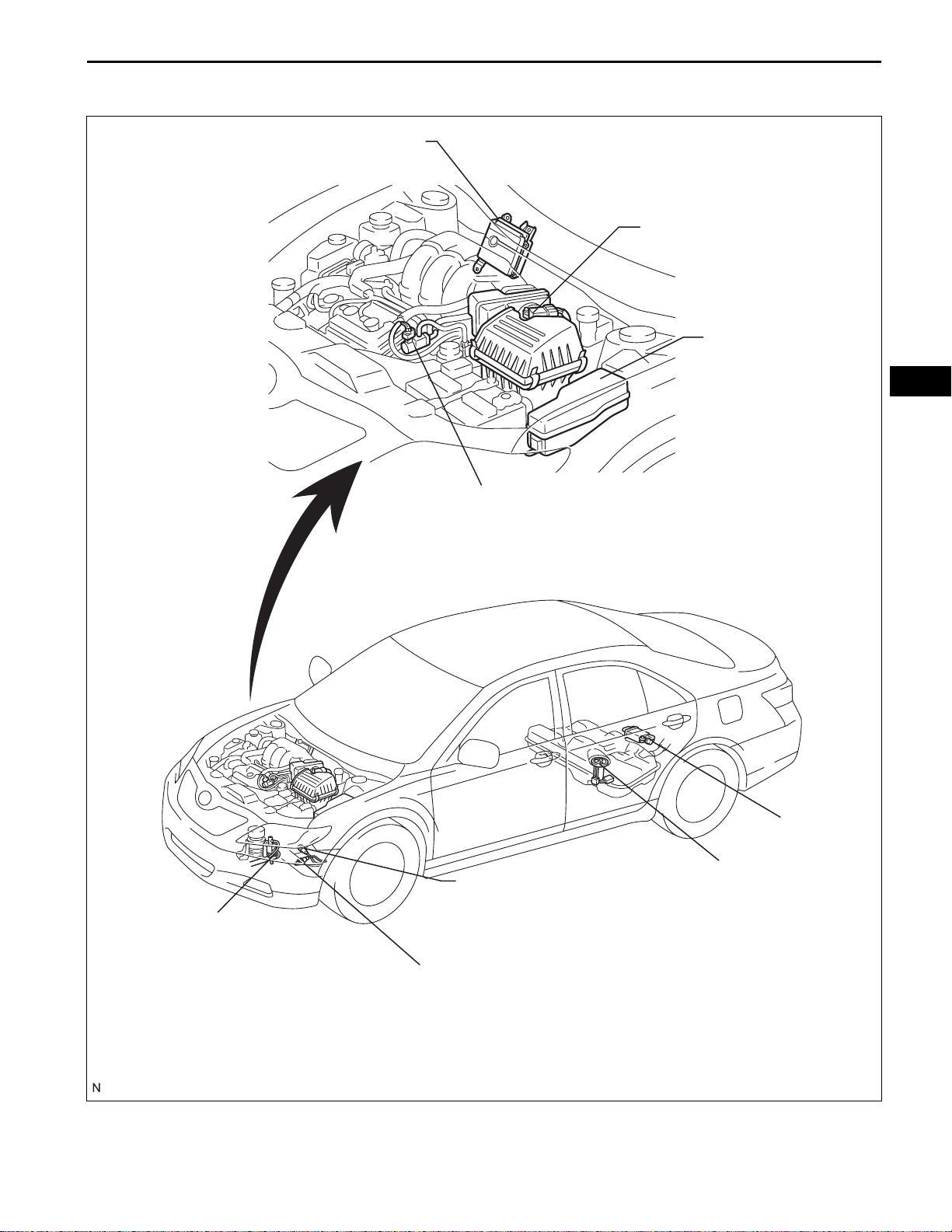
PARTS LOCATION
ES–3
ECM
MASS AIR FLOW METER
ENGINE ROOM R/B
- EFI RELAY
ES
- A/F RELAY
- C/OPN RELAY
- ST RELAY
ACTIVE MOUNT CONTROL VSV
PURGE VSV
HEATED OXYGEN SENSOR
(BANK 1 SENSOR 2)
- ST CUT RELAY
- IG2 RELAY
CANISTER
FUEL PUMP
HEATED OXYGEN SENSOR
(BANK 2 SENSOR 2)
A134870E01
Page 4
ES
ES–4
2GR-FE ENGINE CONTROL SYSTEM – SFI SYSTEM
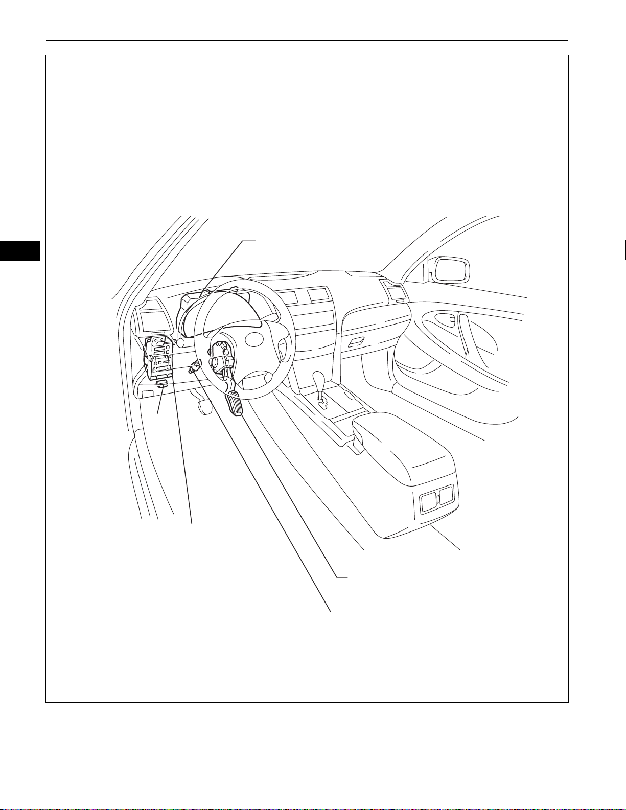
COMBINATION METER
DLC3
INSTRUMENT PANEL J/B
- IGN FUSE
- STOP FUSE
ACCELERATOR PEDAL
STOP LIGHT SWITCH
A139510E01
Page 5
2GR-FE ENGINE CONTROL SYSTEM – SFI SYSTEM
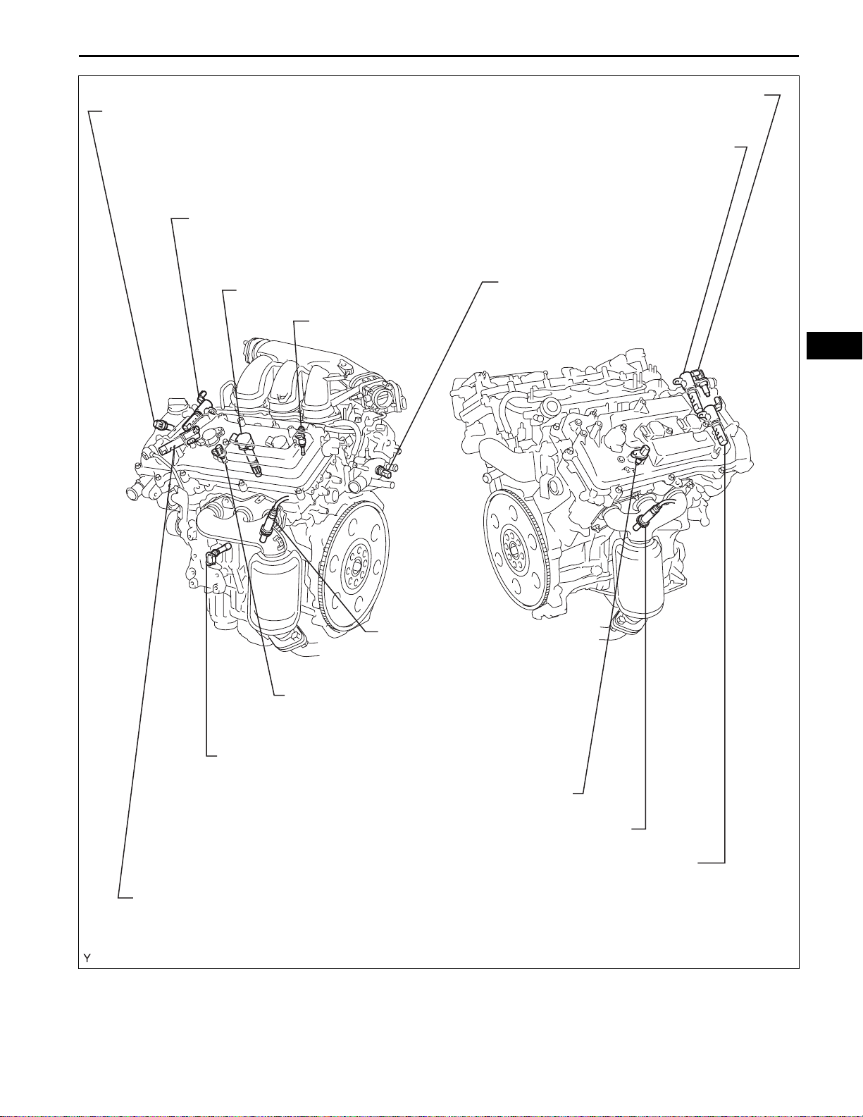
VVT SENSOR FOR INTAKE CAMSHAFT
(BANK 2)
CAMSHAFT TIMING OIL CONTROL VALVE ASSEMBLY
(BANK 2 INTAKE SIDE)
ES–5
VVT SENSOR (BANK 1 INTAKE SIDE)
CAMSHAFT TIMING OIL CONTROL VALVE ASSEMBLY
(BANK 1 INTAKE SIDE)
IGNITION COIL WITH IGNITER
FUEL INJECTOR
AIR FUEL RATIO SENSOR
(BANK 2 SENSOR 1)
ENGINE COOLANT
TEMPERATURE SENSOR
ES
VVT SENSOR FOR EXHAUST CAMSHAFT
(BANK 2)
CRANKSHAFT POSITION SENSOR
VVT SENSOR FOR EXHAUST CAMSHAFT (BANK 1)
AIR FUEL RATIO SENSOR (BANK 1 SENSOR 1)
CAMSHAFT TIMING OIL CONTROL VALVE ASSEMBLY
CAMSHAFT TIMING OIL CONTROL VALVE ASSEMBLY
(BANK 2 EXHAUST SIDE)
A114586E05
Page 6
ES
ES–6
2GR-FE ENGINE CONTROL SYSTEM – SFI SYSTEM
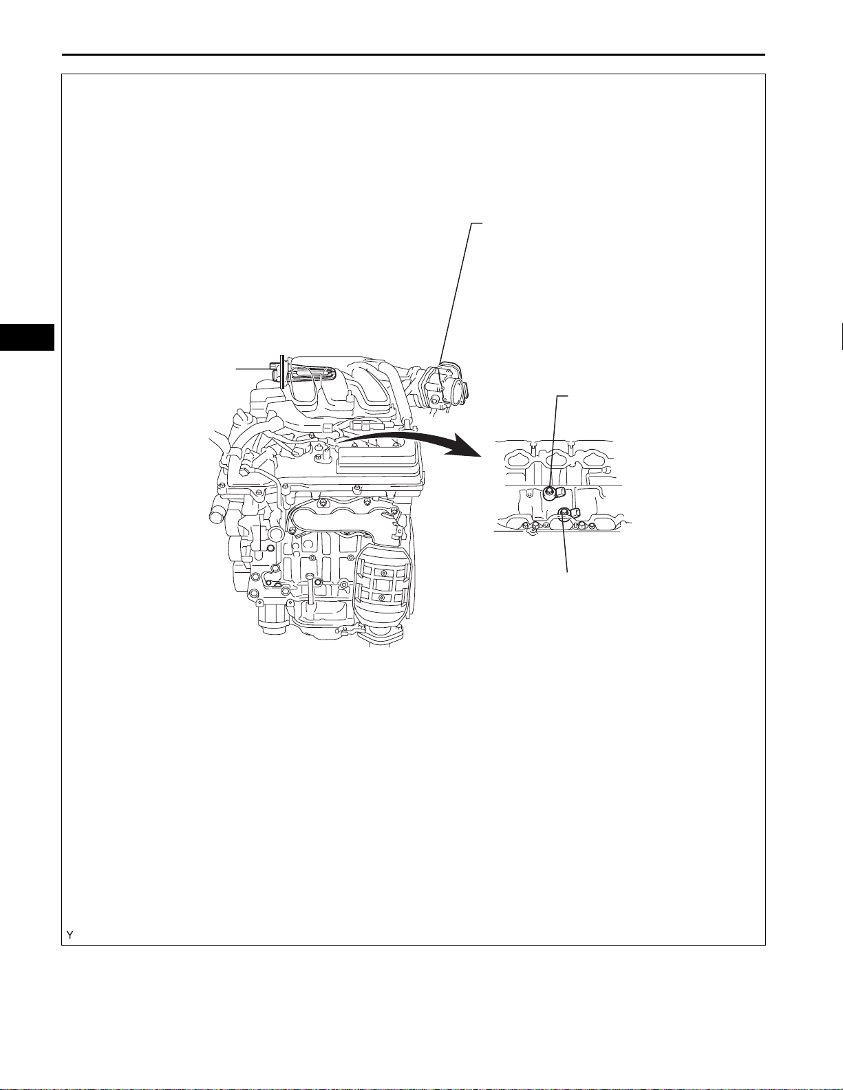
THROTTLE BODY
(THROTTLE POSITION
SENSOR)
ACIS ACTUATOR
KNOCK SENSOR
KNOCK SENSOR
(BANK 1)
(BANK 2)
A114543E04
Page 7
ST/AM2
AM2
AM1
IG2
IG SW
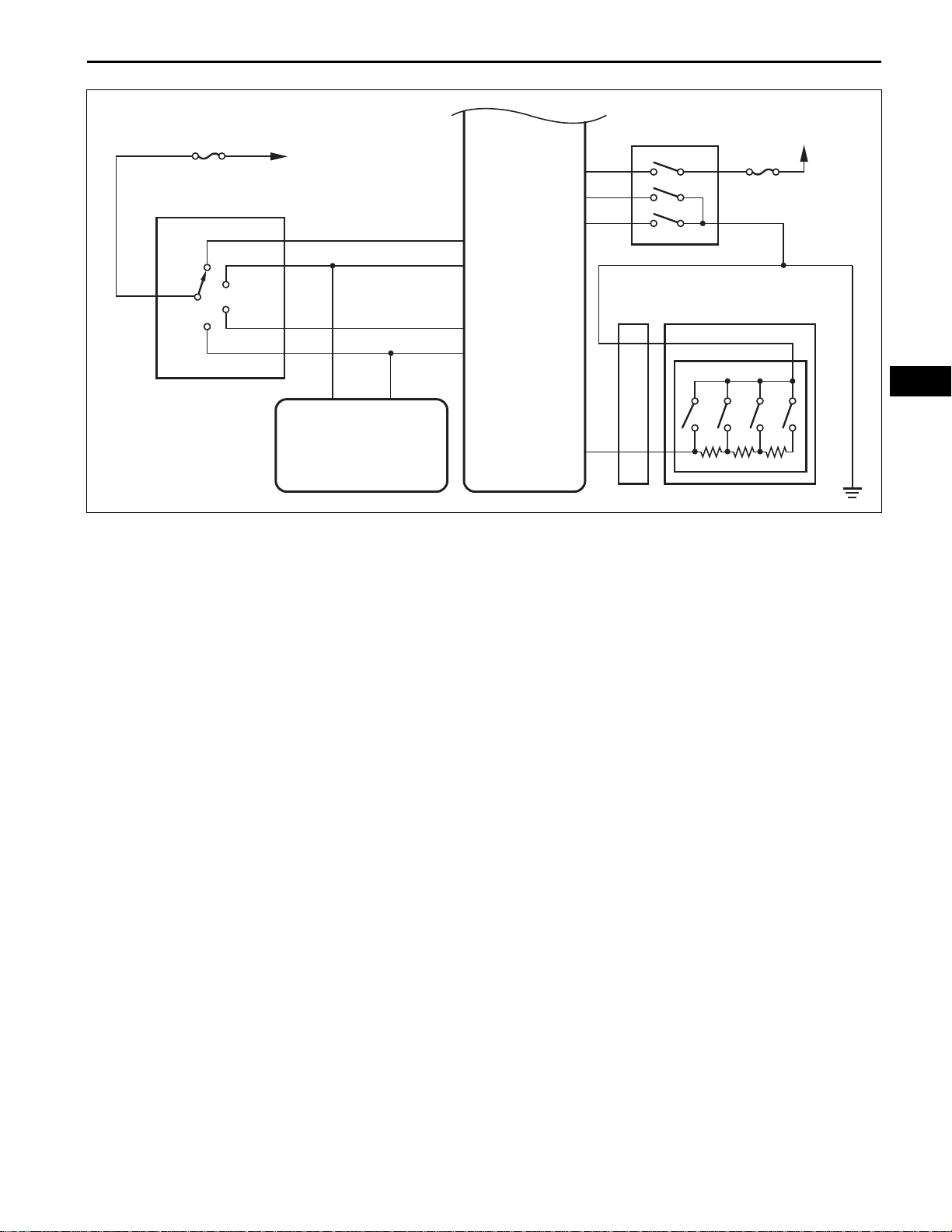
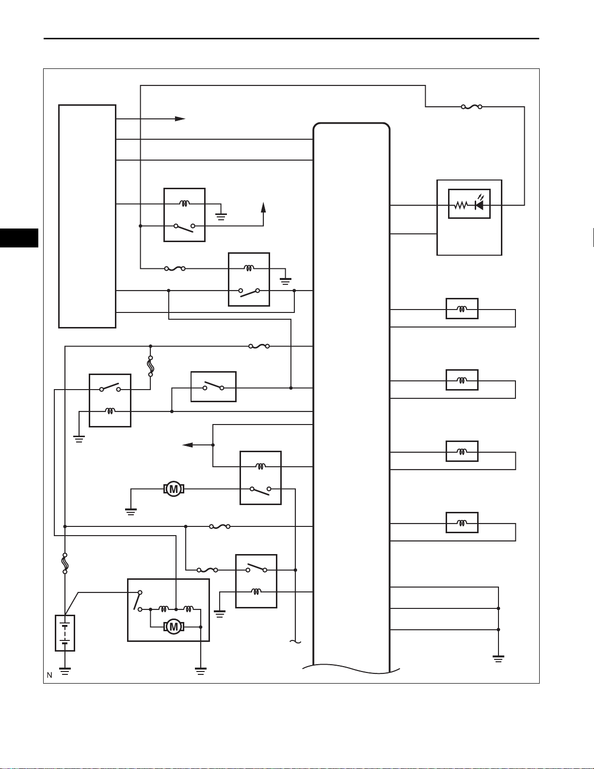
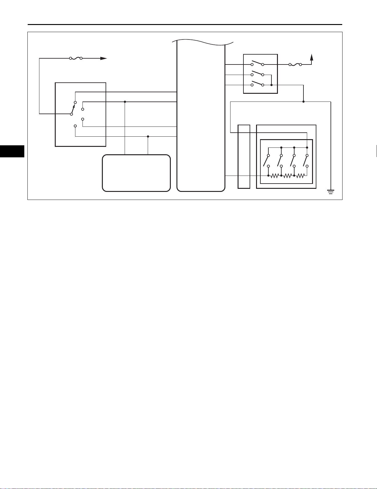
2GR-FE ENGINE CONTROL SYSTEM – SFI SYSTEM
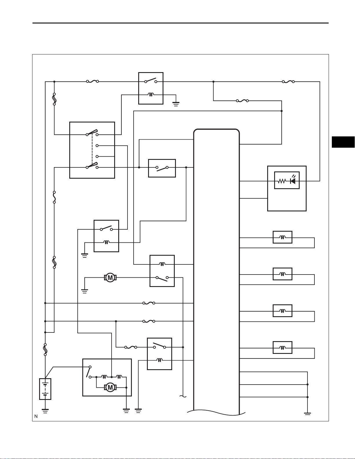
SYSTEM DIAGRAM
1. Without Smart Key System:
IG2
ECM
IG2
ST2
IG1
ST1
PNP SW
NSW
IGSW
STA
W
ES–7
GAUGE No. 2
IGN
ES
Combination Meter
AM1
ALT
FL MAIN
ST
Fuel Pump
EFI MAIN
C/OPN
ETCS
EFI No. 1
EFI
FC
+BM
BATT
MREL
SPD
OC1+
OC1-
OC2+
OC2-
OE1+
OE1-
OE2+
OE2-
MIL
VVT OCV (Intake Side RH)
VVT OCV (Intake Side LH)
VVT OCV (Exhaust Side RH)
VVT OCV (Exhaust Side LH)
Battery
Starter
E02
E05
A
E1
A137635E02
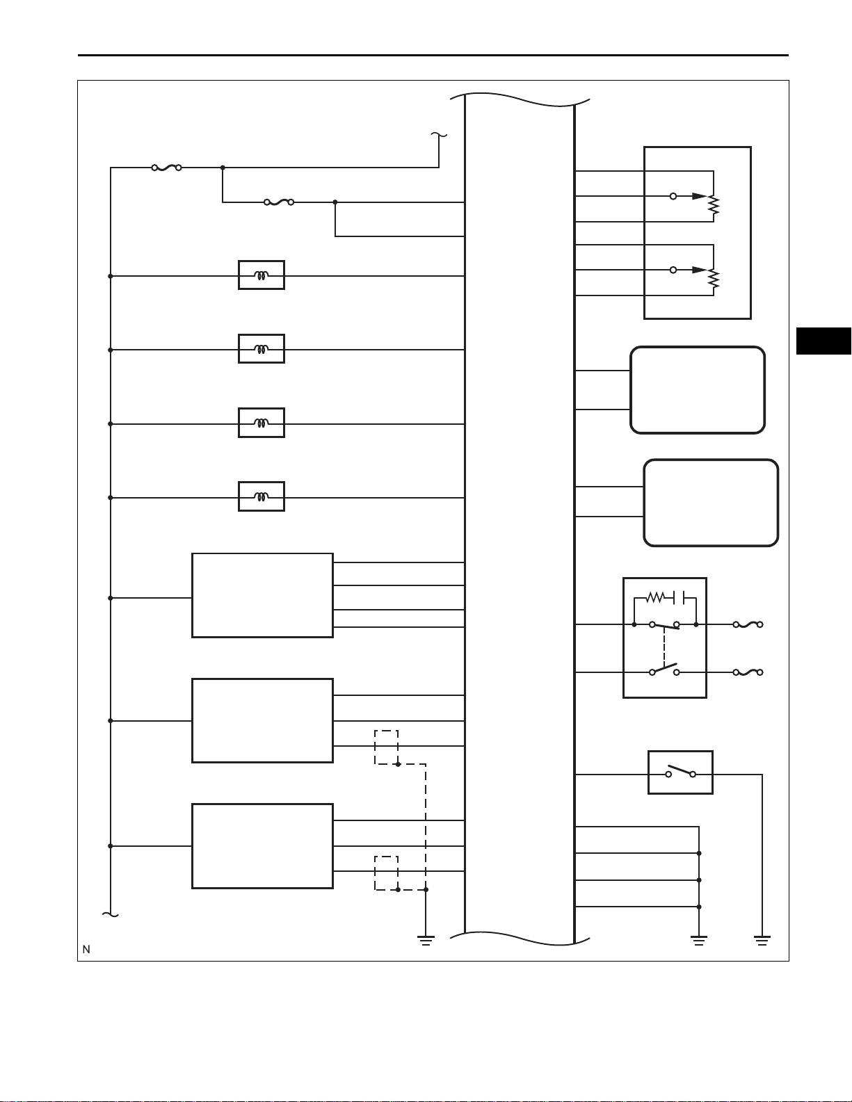
Page 8
ES–8
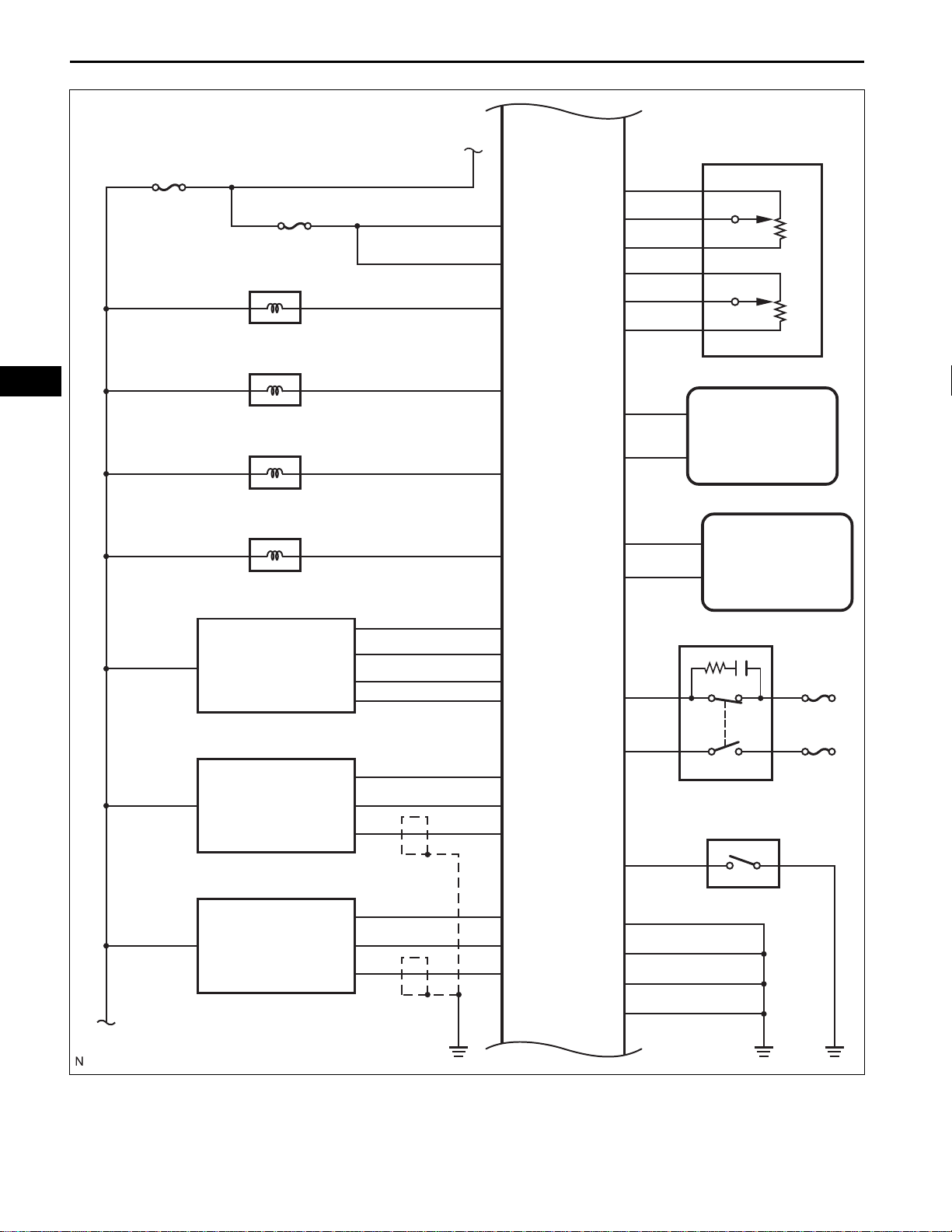
2GR-FE ENGINE CONTROL SYSTEM – SFI SYSTEM
ES
EFI No. 3
EFI No. 2
VSV for ACIS
VSV for EVAP System
VSV for ACIS
VSV for Active Control Mount System
+B
+B2
AICV
PRG
ACIS
ACM
ECM
VCP2
VPA2
EPA2
VCPA
VPA
EPA
CAN+
CAN-
IMO
IMI
A
APP Sensor
Transmission
Control ECU
Transponder Key
ECU
THA
MAF Meter
HO2 Sensor
(Bank 1 Sensor 2)
HO2 Sensor
(Bank 2 Sensor 2)
B
E2G
VG
ETHA
HT1B
EX1B
OX1B
HT2B
EX2B
OX2B
STP
ST1-
Power Steering Oil Pressure SW
PSW
E04
E01
E03
ME01
Stop Light SW
STOP
IGN
A137631E02
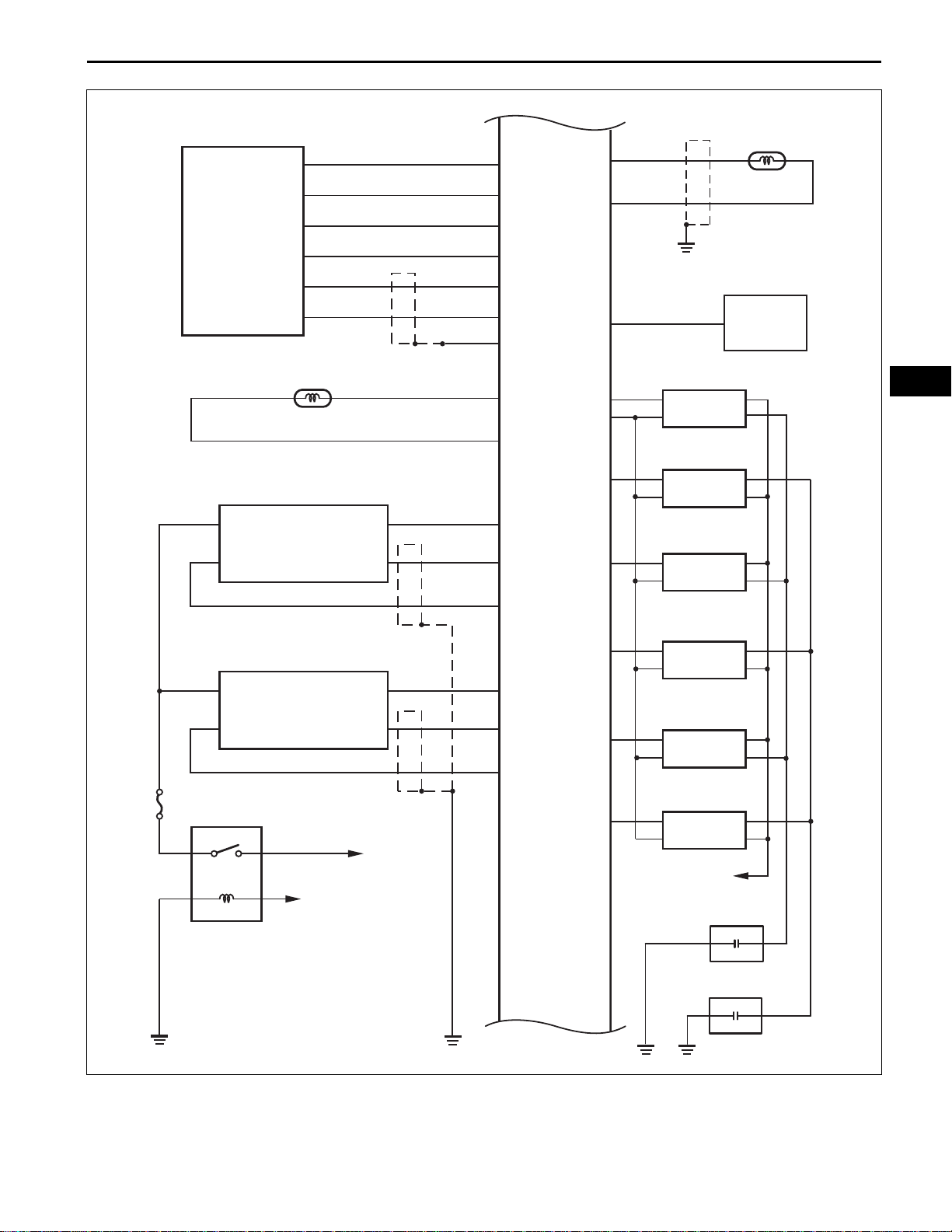
Page 9
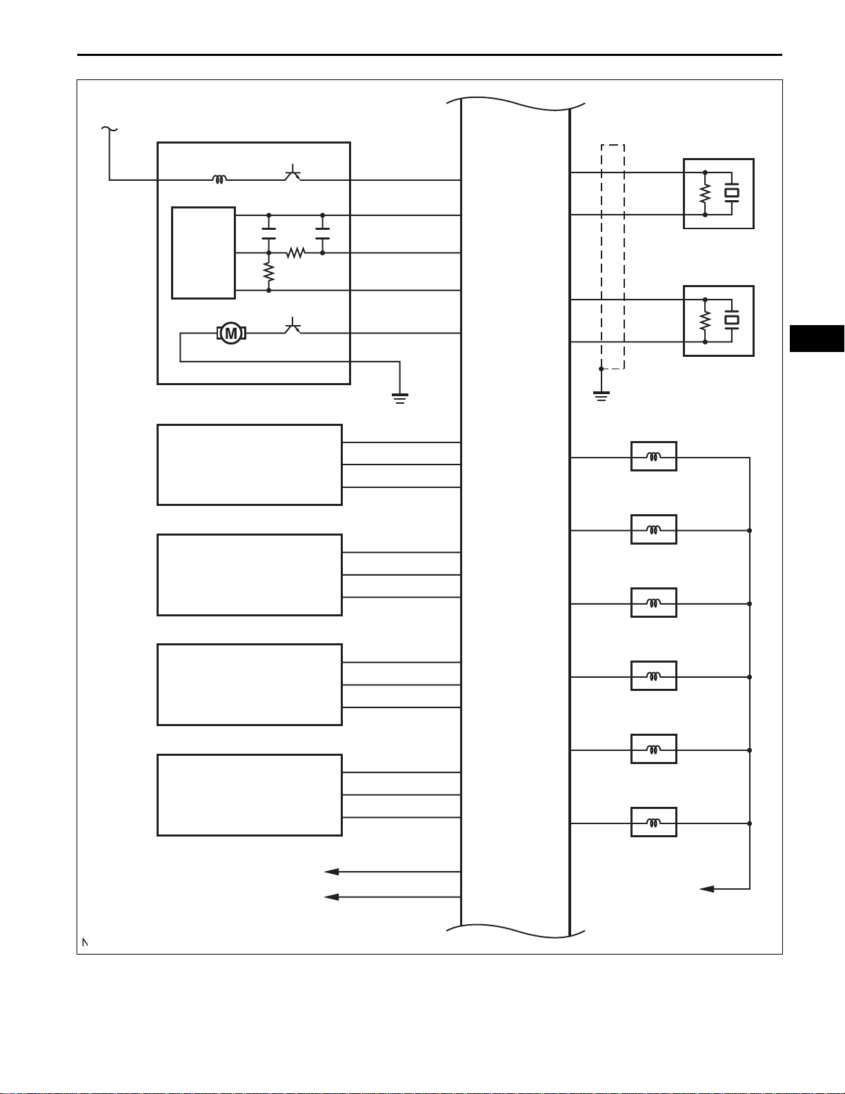
2GR-FE ENGINE CONTROL SYSTEM – SFI SYSTEM
ES–9
B
Canister Pump Module
VVT Sensor
(Bank 1 Intake Side)
ECM
VPMP
EPPM
PPMP
VCPP
MPMP
VV1+
VV1-
VCV1
KNK1
EKNK
KNK2
EKN2
#10
Knock Sensor (Bank 1)
ES
Knock Sensor (Bank 2)
No. 1 Fuel Injector
VVT Sensor
(Bank 2 Intake Side)
VVT Sensor
(Bank 1 Exhaust Side)
VVT Sensor
(Bank 2 Exhaust Side)
To Main Body ECU
VV2+
VV2-
VCV2
EV1+
EV1-
VCE1
EV2+
EV2-
VCE2
CANH
CANL
#20
No. 2 Fuel Injector
#30
No. 3 Fuel Injector
#40
No. 4 Fuel Injector
#50
No. 5 Fuel Injector
#60
No. 6 Fuel Injector
To IG2 Relay
A137632E02
Page 10
ES–10
2GR-FE ENGINE CONTROL SYSTEM – SFI SYSTEM
ECM
VTA1
NE+
Crankshaft Position Sensor
ES
Throttle Body
Assembly
A/F Sensor
(Bank 1 Sensor 1)
ECT Sensor
VCTA
VTA2
ETA
M+
M-
GE01
THW
ETHW
HA1A
A1A+
A1A-
NE-
TC
IGT1
IGF1
IGT2
IGT3
DLC3
Ignition Coil (No. 1)
Ignition Coil (No. 2)
Ignition Coil (No. 3)
Ignition Coil (No. 4)
A/F
A/F Sensor
(Bank 2 Sensor 1)
A/F
To EFI Relay
To Battery
HA2A
A2A+
A2A-
IGT4
Ignition Coil (No. 5)
IGT5
Ignition Coil (No. 6)
IGT6
To IG2 Relay
Noise Filter (RH Side)
Noise Filter (LH Side)
A137633E02
Page 11
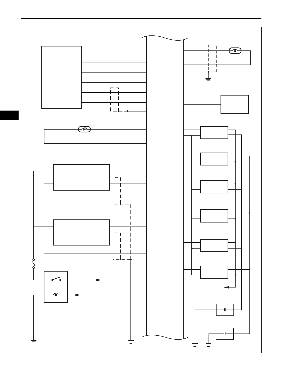
2GR-FE ENGINE CONTROL SYSTEM – SFI SYSTEM
ES–11
GAUGE No. 1
To IG1 Relay
Park / Neutral Position SW
Transmission Control
ECU
ECM
SFTD
SFTU
P
R
N
D
Transmission Control SW
S
ECU IG No. 2
Spiral Cable
Cruise Control SW
To IG1 Relay
ES
CCS
A137634E02
Page 12
ES–12
2GR-FE ENGINE CONTROL SYSTEM – SFI SYSTEM
2. With Smart Key System:
ES
Main Body ECU
ACC
STSW
ACCR
IG2D
STR
STR2
ST
IG2
IGN
ST/AM2
To ECU-ACC Fuse
To IG2 Fuse
ST CUT
ETCS
PNP SW
STSW
ACCR
STAR
+BM
NSW
STA
IGSW
ECM
W
SPD
OC1+
OC1-
OC2+
OC2-
GAUGE No. 2
Combinatiion Meter
MIL
VVT OCV (Intake Side RH)
VVT OCV (Intake Side LH)
VVT OCV (Exhaust Side RH)
FL MAIN
Battery
To IGN Fuse
Fuel Pump
Starter
EFI No. 1
EFI MAIN
C/OPN
EFI
OE1+
FC
BATT
MREL
A
OE1-
VVT OCV (Exhaust Side LH)
OE2+
OE2-
E02
E05
E1
A137630E02
Page 13
2GR-FE ENGINE CONTROL SYSTEM – SFI SYSTEM
ES–13
EFI No. 3
EFI No. 2
VSV for ACIS
VSV for EVAP System
VSV for ACIS
VSV for Active Control Mount System
+B
+B2
AICV
PRG
ACIS
ACM
ECM
VCP2
VPA2
EPA2
VCPA
VPA
EPA
CAN+
CAN-
IMO
IMI
A
APP Sensor
ES
Transmission
Control ECU
Transponder Key
ECU
THA
MAF Meter
HO2 Sensor
(Bank 1 Sensor 2)
HO2 Sensor
(Bank 2 Sensor 2)
B
E2G
VG
ETHA
HT1B
EX1B
OX1B
HT2B
EX2B
OX2B
STP
ST1-
Power Steering Oil Pressure SW
PSW
E04
E01
E03
ME01
Stop Light SW
STOP
IGN
A137631E02
Page 14

ES–14
2GR-FE ENGINE CONTROL SYSTEM – SFI SYSTEM
ES
B
Canister Pump Module
VVT Sensor
(Bank 1 Intake Side)
ECM
VPMP
EPPM
PPMP
VCPP
MPMP
VV1+
VV1-
VCV1
KNK1
EKNK
Knock Sensor (Bank 1)
KNK2
EKN2
Knock Sensor (Bank 2)
#10
No. 1 Fuel Injector
VVT Sensor
(Bank 2 Intake Side)
VVT Sensor
(Bank 1 Exhaust Side)
VVT Sensor
(Bank 2 Exhaust Side)
To Main Body ECU
VV2+
VV2-
VCV2
EV1+
EV1-
VCE1
EV2+
EV2-
VCE2
CANH
CANL
#20
No. 2 Fuel Injector
#30
No. 3 Fuel Injector
#40
No. 4 Fuel Injector
#50
No. 5 Fuel Injector
#60
No. 6 Fuel Injector
To IG2 Relay
A137632E02
Page 15
2GR-FE ENGINE CONTROL SYSTEM – SFI SYSTEM
Crankshaft Position Sensor
ECM
VTA1
NE+
ES–15
Throttle Body
Assembly
A/F Sensor
(Bank 1 Sensor 1)
ECT Sensor
VCTA
VTA2
ETA
M+
M-
GE01
THW
ETHW
HA1A
A1A+
A1A-
NE-
TC
IGT1
IGF1
IGT2
IGT3
DLC3
Ignition Coil (No. 1)
ES
Ignition Coil (No. 2)
Ignition Coil (No. 3)
Ignition Coil (No. 4)
A/F
A/F Sensor
(Bank 2 Sensor 1)
A/F
To EFI Relay
To Battery
HA2A
A2A+
A2A-
IGT4
Ignition Coil (No. 5)
IGT5
Ignition Coil (No. 6)
IGT6
To IG2 Relay
Noise Filter (RH Side)
Noise Filter (LH Side)
A137633E02
Page 16
ES–16
2GR-FE ENGINE CONTROL SYSTEM – SFI SYSTEM
ES
GAUGE No. 1
To IG1 Relay
Park / Neutral Position SW
Transmission Control
ECU
ECM
SFTD
SFTU
P
R
N
D
CCS
Transmission Control SW
S
ECU IG No. 2
Spiral Cable
Cruise Control SW
To IG1 Relay
A137634E02
Page 17
1
NEXT
2
2GR-FE ENGINE CONTROL SYSTEM – SFI SYSTEM
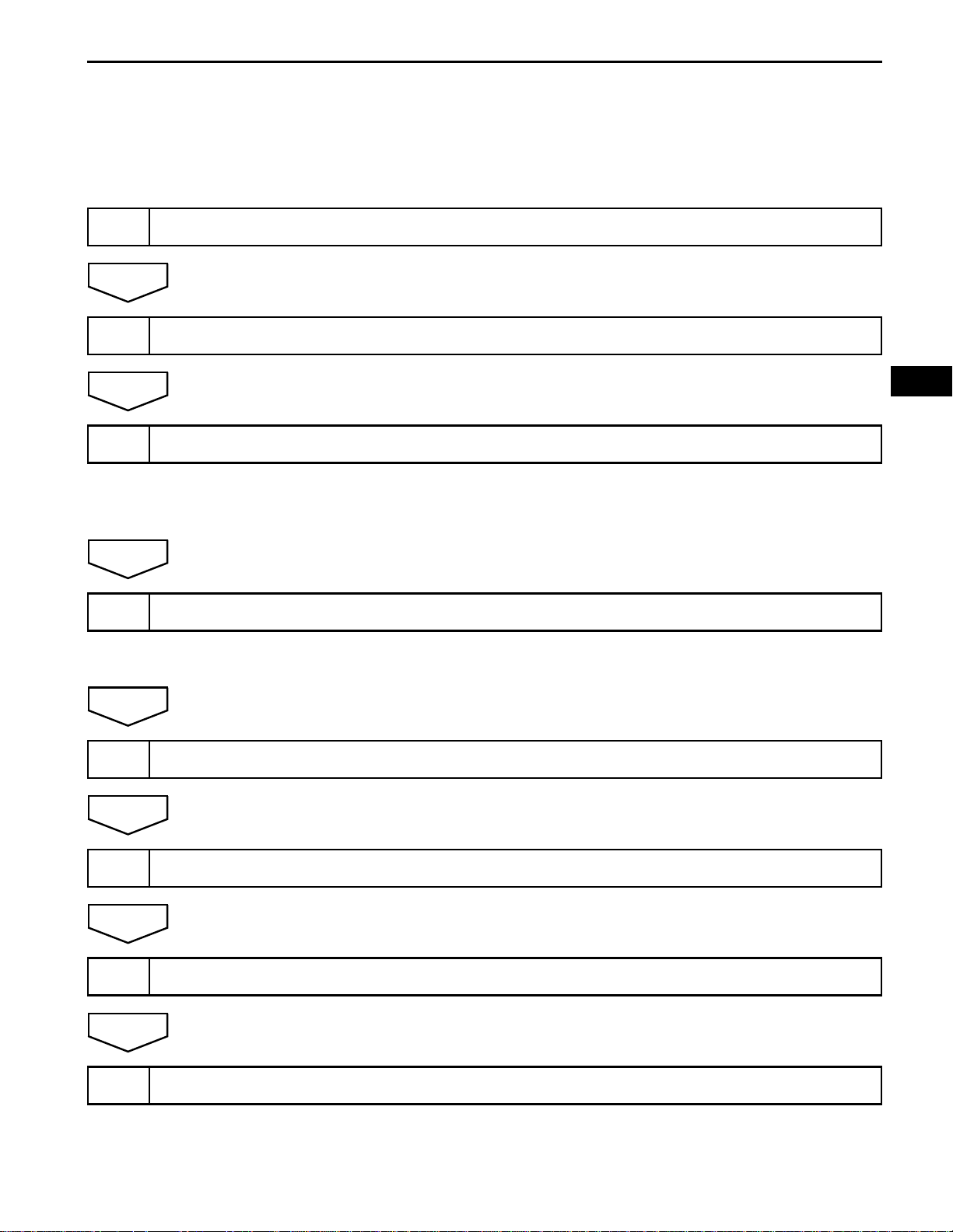
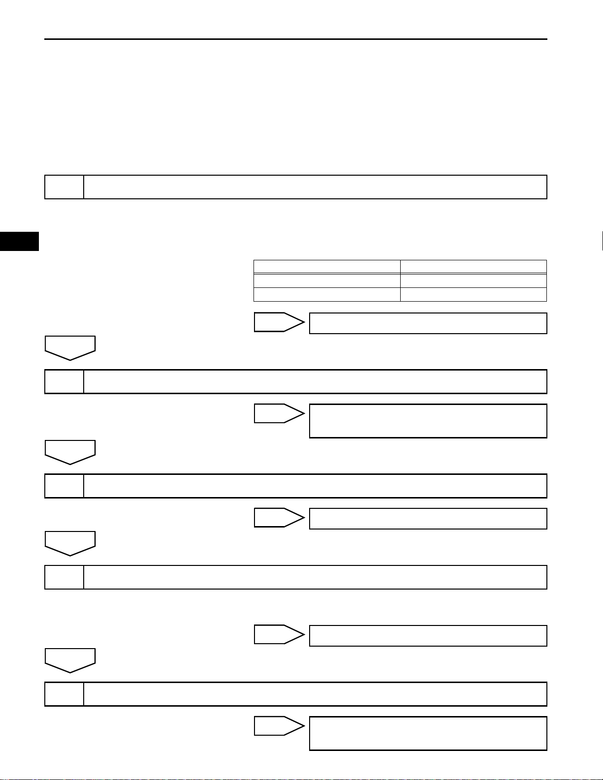
HOW TO PROCEED WITH
TROUBLESHOOTING
HINT:
*: Use the intelligent tester.
VEHICLE BROUGHT TO WORKSHOP
CUSTOMER PROBLEM ANALYSIS
ES–17
NEXT
3
NEXT
4
NEXT
5
NEXT
ES
CONNECT INTELLIGENT TESTER TO DLC3*
HINT:
If the display indicates a communication fault in the tester,
inspect the DLC3.
CHECK DTC AND FREEZE FRAME DATA*
HINT:
Record or print DTCs and freeze frame data, if necessary.
CLEAR DTC AND FREEZE FRAME DATA*
6
NEXT
7
NEXT
8
CONDUCT VISUAL INSPECTION
SET CHECK MODE DIAGNOSIS*
CONFIRM PROBLEM SYMPTOMS
HINT:
If the engine does not start, perform steps 10 and 12 first.
Page 18
ES–18
2GR-FE ENGINE CONTROL SYSTEM – SFI SYSTEM
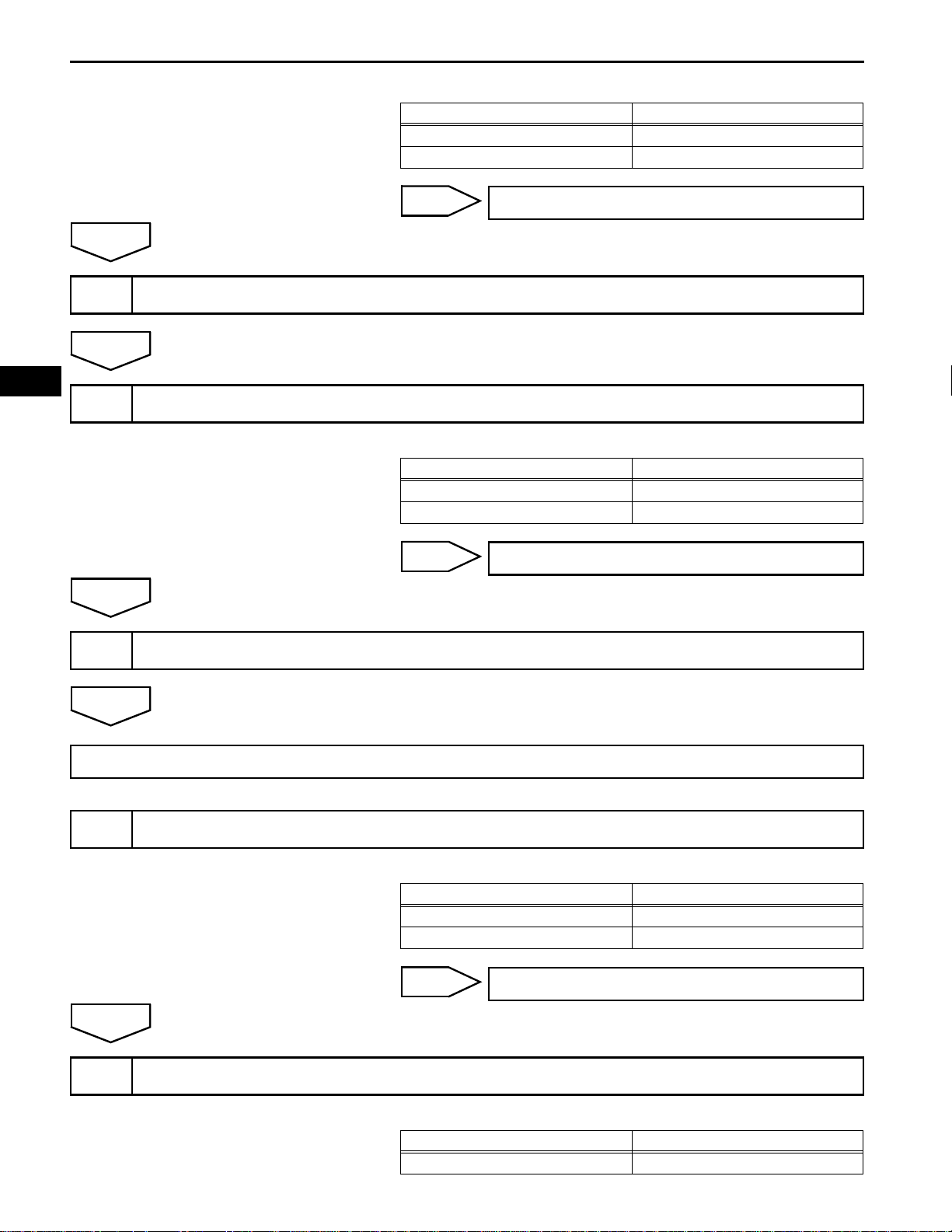
Result
Result Proceed to
Malfunction does not occur A
Malfunction occurs B
ES
A
9
NEXT
10
A
11
SIMULATE SYMPTOMS
CHECK FOR DTCS*
REFER TO DTC CHART
B
Result
B
GO TO STEP 10
Result Proceed to
Trouble code A
No code B
GO TO STEP 12
NEXT
GO TO STEP 14
12
CONDUCT BASIC INSPECTION
A
13
REFER TO PROBLEM SYMPTOMS TABLE
Result
Result Proceed to
Malfunctioning parts not confirmed A
Malfunctioning parts confirmed B
B
GO TO STEP 17
Result
Result Proceed to
Malfunctioning circuit confirmed A
Page 19
2GR-FE ENGINE CONTROL SYSTEM – SFI SYSTEM
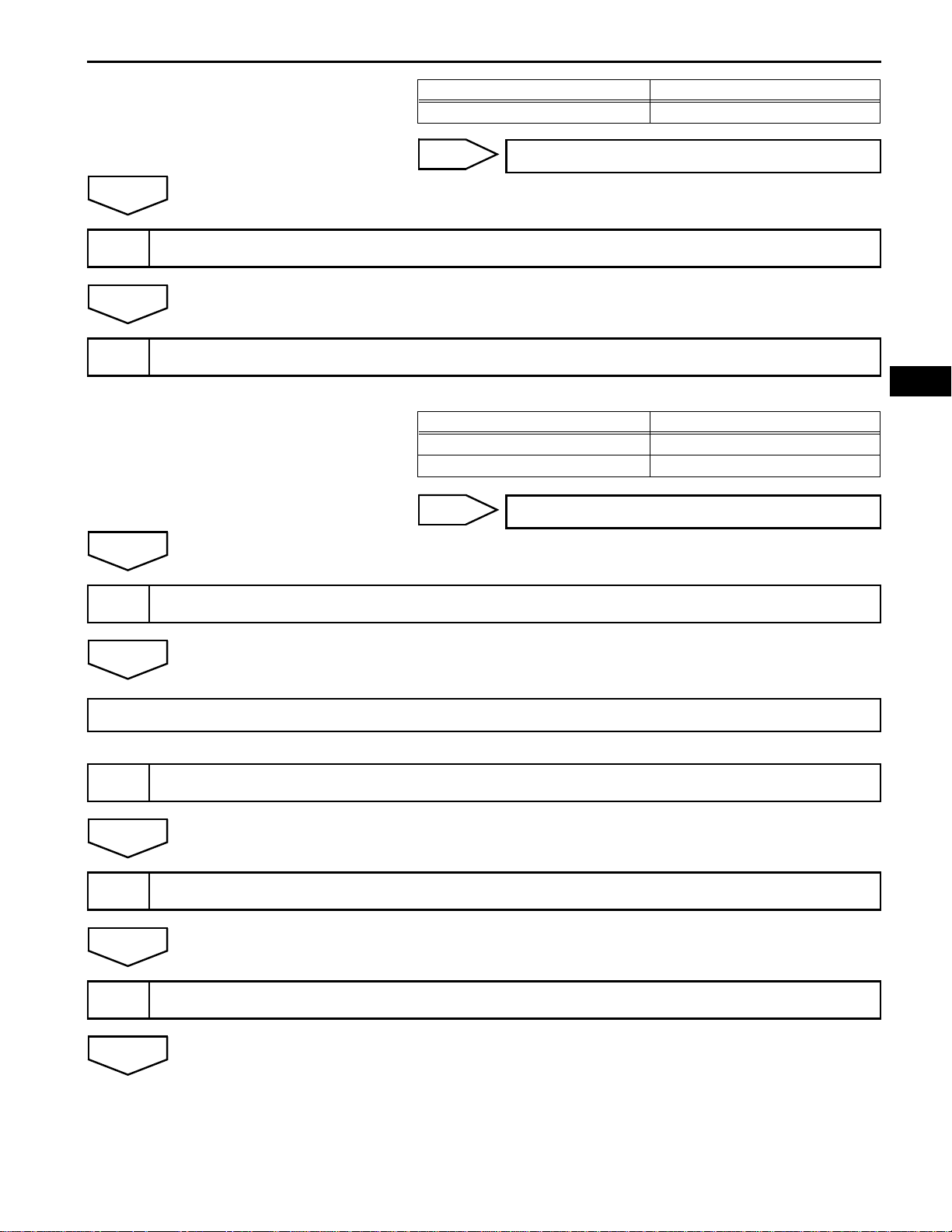
Result Proceed to
Malfunctioning parts confirmed B
ES–19
A
14
NEXT
15
A
16
B
CHECK ECM POWER SOURCE CIRCUIT
CONDUCT CIRCUIT INSPECTION
Result
Malfunction not confirmed A
Malfunction confirmed B
B
CHECK FOR INTERMITTENT PROBLEMS
GO TO STEP 17
ES
Result Proceed to
GO TO STEP 18
NEXT
GO TO STEP 18
17
NEXT
18
NEXT
19
NEXT
CONDUCT PARTS INSPECTION
IDENTIFY PROBLEM
ADJUST AND/OR REPAIR
Page 20

ES–20
2GR-FE ENGINE CONTROL SYSTEM – SFI SYSTEM
ES
20
NEXT
END
CONDUCT CONFIRMATION TEST
Page 21

2GR-FE ENGINE CONTROL SYSTEM – SFI SYSTEM
CHECK FOR INTERMITTENT
PROBLEMS
HINT:
Inspect the vehicle's ECM using check mode. Intermittent
problems are easier to detect with an intelligent tester when
the ECM is in check mode. In check mode, the ECM uses 1
trip detection logic, which is more sensitive to malfunctions
than normal mode (default), which uses 2 trip detection logic.
1. Clear the DTCs.
2. Switch the ECM from normal mode to check mode using
an intelligent tester (See page ES-49).
3. Perform a simulation test (See page IN-40).
4. Check and wiggle the harness(es), connector(s) and
terminal(s) (See page IN-45).
ES–21
ES
Page 22
ES
ES–22
1
2GR-FE ENGINE CONTROL SYSTEM – SFI SYSTEM
BASIC INSPECTION
When the malfunction is not confirmed by the DTC check,
troubleshooting should be carried out in all circuits
considered to be possible causes of the problem. In many
cases, by carrying out the basic engine check shown in the
following flowchart, the location of the problem can be found
quickly and efficiently. Therefore, using this check is essential
when troubleshooting the engine.
CHECK BATTERY VOLTAGE
NOTICE:
Carry out this check with the engine stopped and the
engine switch off.
Result
Result Proceed to
11 V or more OK
Below 11 V NG
OK
CHECK WHETHER ENGINE CRANKS
2
OK
CHECK WHETHER ENGINE STARTS
3
OK
CHECK AIR FILTER
4
NG
NG
NG
(a) Visually check that the air filter is not excessively
contaminated with dirt or oil.
CHARGE OR REPLACE BATTERY
PROCEED TO PROBLEM SYMPTOMS
TABLE
GO TO STEP 6
OK
CHECK IDLING SPEED
5
NG
NG
REPLACE AIR FILTER
TROUBLESHOOT IDLING SPEED AND
PROCEED TO NEXT STEP
Page 23
OK
CHECK FUEL PRESSURE
6
2GR-FE ENGINE CONTROL SYSTEM – SFI SYSTEM
ES–23
NG
OK
CHECK FOR SPARKS
7
NG
OK
PROCEED TO PROBLEM SYMPTOMS TABLE
TROUBLESHOOT FUEL PRESSURE AND
PROCEED TO NEXT STEP
TROUBLESHOOT SPARK AND PROCEED
TO NEXT STEP
ES
Page 24

ES
ES–24
2GR-FE ENGINE CONTROL SYSTEM – SFI SYSTEM
REGISTRATION
NOTICE:
The Vehicle Identification Number (VIN) must be input
into the replacement ECM.
HINT:
The VIN is in the form of a 17-digit alphanumeric vehicle
identification number. An intelligent tester is required to
register the VIN.
1. INPUT INSTRUCTIONS
(a) The general VIN input instructions using an
intelligent tester are explained below:
(b) The arrow buttons (UP, DOWN, RIGHT and LEFT)
and numerical buttons (0 to 9) are used, in order to
input the VIN.
(c) Cursor Operation
To move the cursor around the tester screen, press
the RIGHT and LEFT buttons.
(d) Alphabetical Character Input
(1) Press the UP and DOWN buttons to select the
desired alphabetical character.
(e) Numeric Character Input
(1) Press the numerical button corresponding to
the number that you want to input.
HINT:
Numerical characters can be selected by using
the UP and DOWN buttons.
(f) Correction
(1) When correcting the input character(s), put the
cursor onto the character using the RIGHT or
LEFT button.
(2) Select or input the correct character using the
UP and DOWN buttons, or the numerical
buttons.
(g) Finishing Input Operation
(1) Make sure that the input VIN matches the
vehicle VIN after input.
(2) Press the ENTER button on the tester.
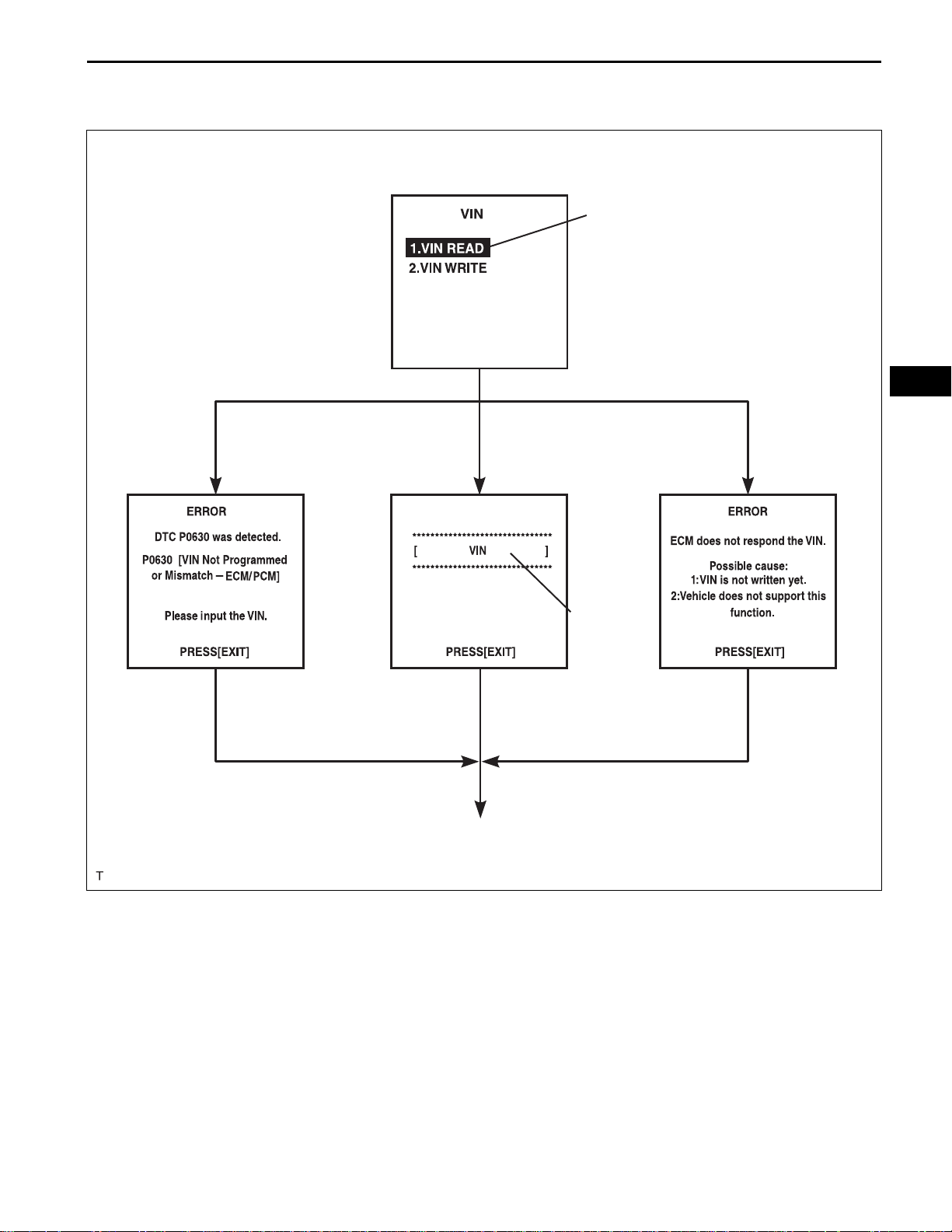
2. READ VIN (Vehicle Identification Number)
(a) The flowchart of the VIN reading process is shown.
This process allows the VIN stored in the ECM to be
read, in order to confirm that the two VINs, provided
with the vehicle and stored in the vehicle's ECM, are
the same.
(b) Read VIN using an intelligent tester.
(c) Check the vehicle's VIN.
(d) Connect the intelligent tester to the DLC3.
(e) Turn the ignition switch on (IG).
(f) Turn the tester on.
Page 25
2GR-FE ENGINE CONTROL SYSTEM – SFI SYSTEM
(g) Enter the following menus: DIAGNOSIS /
ENHANCED OBD ll / VIN.
Menu Screen:
Select VIN READ
ES–25
ES
DTC P0630 Set
[EXIT]
VIN Previously Stored
[EXIT]
To Menu Screen
VIN Not Stored
17-digit VIN
displayed
[EXIT]
A103812E03
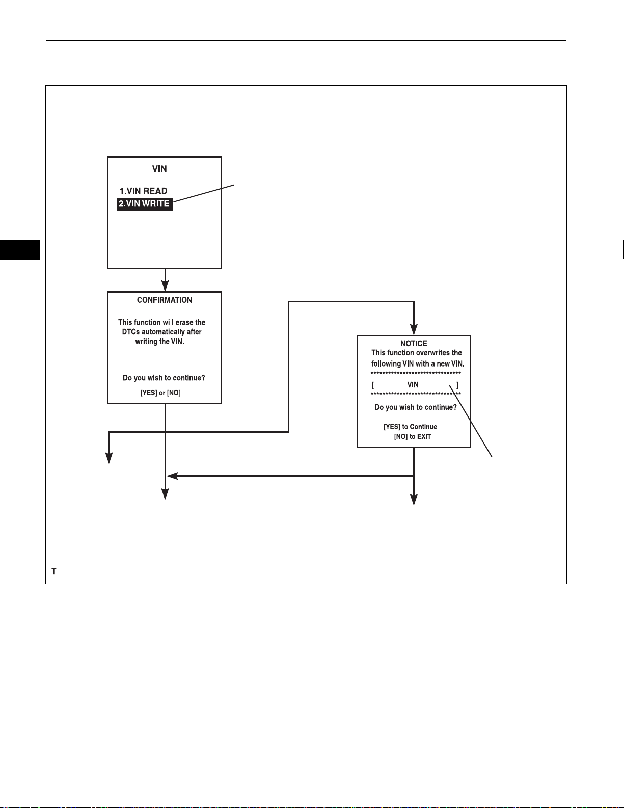
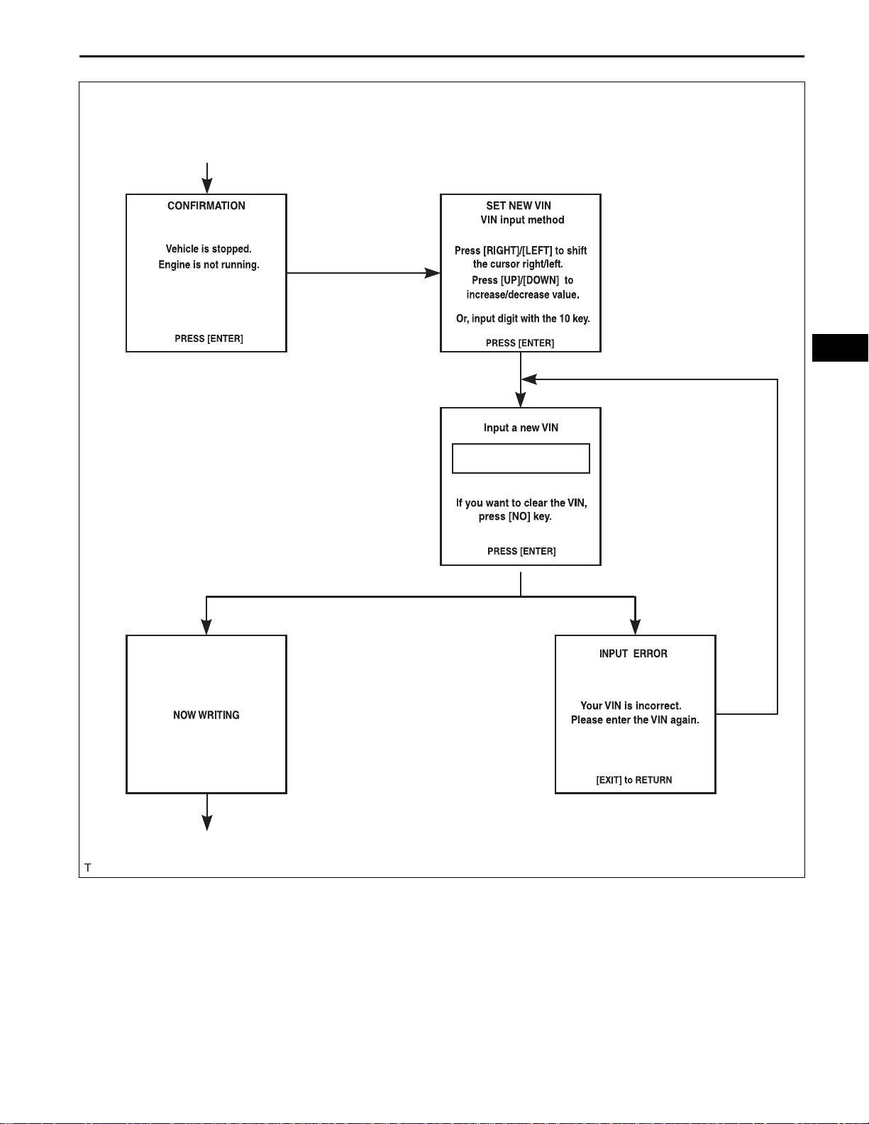
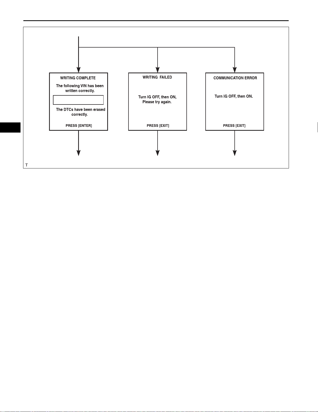
3. WRITE VIN
(a) The flowchart of the VIN writing process is shown.
This process allows the VIN to be input into the
ECM. If the ECM is changed, or the VINs do not
match, the VIN can be registered, or overwritten in
the ECM by following this procedure.
(b) Write VIN using the intelligent tester.
(c) Check the vehicle's VIN.
(d) Connect the intelligent tester to the DLC3.
(e) Turn the ignition switch on (IG).
(f) Turn the tester on.
Page 26
ES
ES–26
2GR-FE ENGINE CONTROL SYSTEM – SFI SYSTEM
(g) Enter the following menus: DIAGNOSIS /
ENHANCED OBD ll / VIN.
Menu Screen:
Select VIN WRITE
VIN Previously Stored
To Menu
Screen
[YES][NO]
[YES]
Continue to next illustration
[YES]
17-digit VIN displayed
[NO]
To Menu Screen
A103813E01
Page 27
2GR-FE ENGINE CONTROL SYSTEM – SFI SYSTEM
New Registration
ES–27
Input Instructions
[ENTER]
ES
[ENTER]
Continue to next illustration
[ENTER]
[ENTER]
Input Error
[EXIT]
A103814E03
Page 28
ES
ES–28
2GR-FE ENGINE CONTROL SYSTEM – SFI SYSTEM
Writing Successful Writing Error Communication Error
[ENTER] [EXIT] [EXIT]
To Menu Screen To Menu Screen To Menu Screen
A103815E03
Page 29

2GR-FE ENGINE CONTROL SYSTEM – SFI SYSTEM
CHECKING MONITOR STATUS
The purpose of the monitor result (mode 06) is to allow
access to the results for on-board diagnostic monitoring tests
of specific components/systems that are not continuously
monitored. Examples are catalyst, evaporative emission
(EVAP) and thermostat.
The monitor result allows the OBD II scan tool to display the
monitor status, test value, minimum test limit and maximum
test limit. These data are displayed after the vehicle has been
driven to run the monitor.
When the test value is not between the minimum test limit
and maximum test limit, the ECM (PCM) interprets this as a
malfunction. When the component is not malfunctioning, if the
difference of the test value and test limit is very small, the
component will malfunction in the near future.
Perform the following instructions to view the monitor status.
Although the Toyota diagnostic tester is used in the following
instructions, it can be checked using a generic OBD II scan
tool. Refer to your scan tool operator's manual for specific
procedures.
1. PERFORM MONITOR DRIVE PATTERN
The monitor results and test values can be checked with
the OBD II scan tool or the intelligent tester. The engine
control module (ECM) monitors the emissions-related
components such as the thermostat, catalyst converter
and evaporative emissions (EVAP), and determines
whether they are functioning normally or not. When
monitoring is finished, the ECM stores the monitor
results and the test values. The monitor result indicates
whether the component is functioning normally or not.
The test value is the value that was used to determine
the monitor result. If the test value is outside of the test
limit (malfunction criterion), the ECM determines the
component is malfunctioning. Some emissions-related
components have multiple test values to determine
monitor result. If one of these test values is outside of the
test limit, the ECM determines the component is
malfunctioning.
(a) Connect the intelligent tester to the DLC3.
(b) Start the engine and turn the tester on.
(c) Clear the DTCs.
(d) Run the vehicle in accordance with the applicable
drive pattern described in READINESS MONITOR
DRIVE PATTERN (See page ES-28). DO NOT turn
the engine switch off.
NOTICE:
The test results will be lost if the engine switch
is turned off.
ES–29
ES
Page 30

ES
ES–30
2GR-FE ENGINE CONTROL SYSTEM – SFI SYSTEM
2. ACCESS MONITOR RESULT
(a) Select the following menus on the intelligent tester:
DIAGNOSIS, ENHANCED OBDII, MONITOR INFO
and MONITOR RESULT. The monitor status
appears after the component name.
• INCMP: The component has not been monitored
yet.
• PASS: The component is functioning normally.
• FAIL: The component is malfunctioning.
(b) Confirm that the component is either PASS or FAIL.
(c) Select the component and press ENTER. The
accuracy test value appears if the monitor status is
either PASS or FAIL.
HINT:
The monitor result might be PASS on rare
occasions even if the Malfunction Indicator Lamp
(MIL) is illuminated. This indicates that the system
was malfunctioning in the previous driving cycle.
This might be caused by an intermittent problem.
3. CHECK COMPONENT STATUS
(a) Compare the test value with the minimum test limit
(MIN LIMIT) and maximum test limit (MAX LIMIT).
(b) If the test value is between the minimum test limit
and maximum test limit, the component is
functioning normally. If not, the component is
malfunctioning. The test value is usually significantly
higher or lower than the test limit. If the test value is
on the borderline of the test limit, the component will
malfunction in the near future.
HINT:
The monitor result might be PASS on rare occasions even if
the Malfunction Indicator Lamp (MIL) is illuminated. This
indicates that the system was malfunctioning in the previous
driving cycle. This might be caused by an intermittent
problem.
4. MONITOR RESULT INFORMATION
If you use a generic scan tool, multiply the test value by
the scaling value listed below.
A/F Sensor Bank 1:
Monitor ID Test ID Scaling Unit Description
$01 $8E Multiply by 0.0003 No dimension A/F sensor deterioration level
$01 $91 Multiply by 0.004 mA A/F sensor current
HO2S Bank 1 Sensor 2:
Monitor ID Test ID Scaling Unit Description
$02 $07 Multiply by 0.001 V Minimum sensor voltage
$02 $08 Multiply by 0.001 V Maximum sensor voltage
$02 $8F Multiply by 0.003 g Maximum oxygen storage capacity
A/F Sensor Bank 2:
Monitor ID Test ID Scaling Unit Description
$05 $8E Multiply by 0.0003 No dimension A/F sensor deterioration level
$05 $91 Multiply by 0.004 mA A/F sensor current
Page 31

2GR-FE ENGINE CONTROL SYSTEM – SFI SYSTEM
HO2S Bank 2 Sensor 2:
Monitor ID Test ID Scaling Unit Description
$06 $07 Multiply by 0.001 V Minimum sensor voltage
$06 $08 Multiply by 0.001 V Maximum sensor voltage
$06 $8F Multiply by 0.003 g Maximum oxygen storage capacity
Catalyst-Bank 1:
Monitor ID Test ID Scaling Unit Description
$21 $A9 Multiply by 0.003 No dimension Oxygen storage capacity of catalyst-bank 1
Catalyst-Bank 2:
Monitor ID Test ID Scaling Unit Description
$22 $A9 Multiply by 0.003 No dimension Oxygen storage capacity of catalyst-bank 2
EVAP:
Monitor ID Test ID Scaling Unit Description
$3D $C9 Multiply by 0.001 kPa Test value for small leak (P0456)
$3D $CA Multiply by 0.001 kPa Test value for gross leak (P0455)
$3D $CB Multiply by 0.001 kPa Test value for leak detection pump OFF stuck (P2401)
$3D $CD Multiply by 0.001 kPa Test value for leak detection pump ON stuck (P2402)
$3D $CE Multiply by 0.001 kPa Test value for vent valve OFF stuck (P2420)
$3D $CF Multiply by 0.001 kPa Test value for vent valve ON stuck (P2419)
$3D $D0 Multiply by 0.001 kPa Test value for reference orifice low flow (P043E)
$3D $D1 Multiply by 0.001 kPa Test value for reference orifice high flow (P043F )
$3D $D4 Multiply by 0.001 kPa Test value for purge VSV close stuck (P0441)
$3D $D5 Multiply by 0.001 kPa Test value for purge VSV open stuck (P0441)
$3D $D7 Multiply by 0.001 kPa Test value for purge flow insufficient (P0441)
ES–31
ES
Misfire:
Monitor ID Test ID Scaling Unit Description
$A1 $0B Multiply by 1 Time
$A1 $0C Multiply by 1 Time
$A2 $0B Multiply by 1 Time
$A2 $0C Multiply by 1 Time
$A3 $0B Multiply by 1 Time
$A3 $0C Multiply by 1 Time
$A4 $0B Multiply by 1 Time
$A4 $0C Multiply by 1 Time
$A5 $0B Multiply by 1 Time
$A5 $0C Multiply by 1 Time
$A6 $0B Multiply by 1 Time
$A6 $0C Multiply by 1 Time
$A7 $0B Multiply by 1 Time
Exponential Weighted Moving Average (EWMA) misfire for all
cylinders: Misfire counts for last ten driving cycles-Total
Misfire rate for all cylinders: Misfire counts for last/current driving
cycles-Total
EWMA misfire for cylinder 1: Misfire counts for last ten driving cyclesTotal
Misfire rate for cylinder 1: Misfire counts for last/current driving cycleTotal
EWMA misfire for cylinder 2: Misfire counts for last ten driving cyclesTotal
Misfire rate for cylinder 2: Misfire counts for last/current driving cycleTotal
EWMA misfire for cylinder 3: Misfire counts for last ten driving cyclesTotal
Misfire rate for cylinder 3: Misfire counts for last/current driving cycleTotal
EWMA misfire for cylinder 4: Misfire counts for last ten driving cyclesTotal
Misfire rate for cylinder 4: Misfire counts for last/current driving cycleTotal
EWMA misfire for cylinder 5: Misfire counts for last ten driving cyclesTotal
Misfire rate for cylinder 5: Misfire counts for last/current driving cycleTotal
EWMA misfire for cylinder 6: Misfire counts for last ten driving cyclesTotal
Page 32

ES
ES–32
Monitor ID Test ID Scaling Unit Description
$A7 $0C Multiply by 1 Time
2GR-FE ENGINE CONTROL SYSTEM – SFI SYSTEM
Misfire rate for cylinder 6: Misfire counts for last/current driving cycleTotal
Rear Oxygen Sensor Heater:
Monitor ID Test ID Scaling Unit Description
$42 $91 Multiply by 0.001 Ohm Oxygen sensor heater resistance bank 1 sensor 2
$46 $91 Multiply by 0.004 Ohm Oxygen sensor heater resistance bank 2 sensor 2
Page 33

2GR-FE ENGINE CONTROL SYSTEM – SFI SYSTEM
READINESS MONITOR DRIVE
PATTERN
1. PURPOSE OF READINESS TESTS
• The On-Board Diagnostic (OBD II) system is
designed to monitor the performance of emissionrelated components, and indicate any detected
abnormalities with DTCs (Diagnostic Trouble Codes).
Since various components need to be monitored in
different driving conditions, the OBD II system is
designed to run separate monitoring programs called
Readiness Monitors.
• The intelligent tester's software must be version 9.0 or
newer to view the Readiness Monitor status. To view
the status, select the following menu items:
DIAGNOSIS / ENHANCED OBD II / MONITOR INFO
/ MONITOR STATUS.
• When the Readiness Monitor status reads COMPL
(complete), the necessary conditions have been met
for running the performance tests for that Readiness
Monitor.
• A generic OBD II scan tool can also be used to view
the Readiness Monitor status.
HINT:
Many Inspection and Maintenance (I/M) programs
require a vehicle's Readiness Monitor status to show
COMPL before beginning emission tests.
The Readiness Monitor will be reset to INCMPL
(incomplete) if:
• The ECM has lost battery power or broken a fuse.
• DTCs have been cleared.
• The conditions for running the Readiness Monitor
have not been met.
If the Readiness Monitor status shows INCMPL, follow
the appropriate Readiness Monitor Drive Pattern to
change the status to COMPL.
CAUTION:
Strictly observe posted speed limit s, traffic laws, and
road conditions when performing these drive
patterns.
NOTICE:
These drive patterns represent the fastest me thod of
satisfying all conditions necessary to achieve
complete status for each specific Readiness
Monitor.
In the event of a drive pattern being interrupted
(possibly due to factors such as traffic conditions),
the drive pattern can be resumed. In most cases, the
Readiness Monitor will still achieve complete status
upon completion of the drive pattern.
To ensure completion of the Readiness Monitors,
avoid sudden changes in vehicle load and speed
(driving up and down hills and/or sudden
acceleration).
ES–33
ES
Page 34

ES–34
2GR-FE ENGINE CONTROL SYSTEM – SFI SYSTEM
2. CATALYST MONITOR (ACTIVE AIR-FUEL RATIO
CONTROL TYPE)
Vehicle Speed
NOTICE:
ES
Between 40 mph and
70 mph (64 km/h and
113 km/h)
Idling
Ignition Switch off
This test will not be completed if
the vehicle is driven under absolute
constant speed condition such as
with cruise control activated.
Warm up
Note: Even when vehicle stops during driving pattern, the test can be resumed
10 minutes
Time
(a) Preconditions
The monitor will not run unless:
• The MIL is OFF.
(b) Drive Pattern
(1) Connect an intelligent tester.
(2) Turn the ignition switch on (IG).
(3) Turn the tester or scan tool ON.
(4) Clear the DTCs.
(5) Start the engine and warm it up.
(6) Drive the vehicle at between 40 mph and 70
mph (64 km/h and 113 km/h) for at least 10
minutes.
(c) Monitor Status
(1) Check the Readiness Monitor status displayed
on the tester.
(2) If the status does not switch to COMPL
(complete), extend the driving time.
3. EVAP MONITOR (KEY-OFF TYPE)
(a) Preconditions
The monitor will not run unless:
• The fuel tank is less than 90% full.
• The altitude is less than 8,000 ft (2,450 m).
• The vehicle is stationary.
• The engine coolant temperature is between
4.4°C and 35°C (40°F to 95°F).
• The intake air temperature is between 4.4°C and
35°C (40°F to 95°F).
• Vehicle was driven in the city area (or on freeway) for 10 minutes or more.
(b) Monitor Conditions
(1) Turn the ignition switch off and wait for 6 hours.
HINT:
Do not start the engine until checking Readiness
Monitor status. If the engine is started, the step
described above must be repeated.
A079199E85
Page 35

Monitor Drive Pattern:
ECT: 75°C (167°F) or more
Vehicle Speed
2GR-FE ENGINE CONTROL SYSTEM – SFI SYSTEM
(c) Monitor Status
(1) Connect an intelligent tester to the DLC3.
(2) Turn the ignition switch on (IG).
(3) Turn the tester or scan tool on.
(4) Check the Readiness Monitor status displayed
on the tester or scan tool.
If the status does not switch to COMPL
(complete), restart the engine, make sure that
the preconditions have been met, and then
perform the Monitor Conditions again.
4. A/F SENSOR AND HO2S MONITORS
Accelerator Pedal Depressed
At least 3 times
ES–35
Accelerator
Pedal Released
(Fuel-cut)
ES
Idling
38 to 75 mph
(60 to 120 km/h)
Warming up
10 minutes or more
(a) Preconditions
(b) Drive Pattern for front A/F sensor and HO2 sensor
40 mph (64 km/h)
or more
6 mph (10
km/h)
Time
10 seconds or more
4 seconds or more
G039003E12
The monitor will not run unless:
• 2 minutes or more have elapsed sin ce the engine
was started.
• The Engine Coolant Temperature (ECT) is 75°C
(167°F) or more.
• Cumulative driving time at a vehicle speed of 30
mph (48 km/h) or more exceeds 6 minutes.
• Air-fuel ratio feedback control is performed.
• Fuel-cut control is performed for 8 seconds or
more (for the Rear HO2 Sensor Monitor).
(1) Connect an intelligent tester to the DLC3.
(2) Turn the ignition switch on (IG).
(3) Turn the tester on.
(4) Clear the DTCs.
(5) Start the engine, and warm it up until the ECT
reaches 75°C (167°F) or higher.
(6) Drive the vehicle at 38 mph (60 km/h) or more
for at least 10 minutes.
(7) Change the transmission to the 2nd gear.
(8) Accelerate the vehicle to 40 mph (64 km/h) or
more by depressing the accelerator pedal for at
least 10 seconds (Procedure "A").
Page 36

ES
ES–36
2GR-FE ENGINE CONTROL SYSTEM – SFI SYSTEM
(9) Soon after performing procedure "A" above,
release the accelerator pedal for at least 4
seconds without depressing the brake pedal, in
order to execute fuel-cut control (Procedure "B").
(10)Allow the vehicle to decelerate until the vehicle
speed declines to less than 6 mph (10 km/h)
(Procedure "C").
(11)Repeat procedures from "A" through "C" above
at least 3 times in one driving cycle.
(c) Monitor Status
(1) Check the Readiness Monitor status displayed
on the tester.
(2) If the status does not switch to COMPL
(complete), make sure that the preconditions
have been met and then perform the Drive
Pattern again.
5. AIR-FUEL RA TIO (A/F) AND HEATED OXYGEN (HO2)
SENSOR HEATER MONI TORS (FRONT A/F AND
REAR HO2 SENSOR TYPE)
Vehicle Speed
25 mph
(40 km/h)
Idling
Ignition Switch off
10 minutes or more
2 minutes or more
A078886E24
(a) Preconditions
The monitor will not run unless:
• The MIL is OFF.
(b) Drive Pattern
(1) Connect an intelligent tester to the DLC3.
(2) Turn the ignition switch on (IG).
(3) Clear the DTCs.
(4) Start the engine.
(5) Allow the engine to idle for 10 minutes or more.
(6) Drive the vehicle at 25 mph (40 km/h) or more
for at least 2 minutes.
Page 37

2GR-FE ENGINE CONTROL SYSTEM – SFI SYSTEM
(c) Monitor Status
(1) Check the Readiness Monitor status displayed
on the tester or scan tool.
If the status does not switch to COMPL
(complete), make sure that the preconditions
have been met, and repeat the Drive Pattern.
ES–37
ES
Page 38

ES
ES–38
2GR-FE ENGINE CONTROL SYSTEM – SFI SYSTEM
SFI SYSTEM
Symptom Suspected area See page
Without Smart Key System: Engine does not crank
(Does not start)
With Smart Key System: Engine does not crank (Does
not start)
No initial combustion (Does not start)
Engine cranks normally but difficult to start
Difficult to start with cold engine
Difficult to start with warm engine
PROBLEM SYMPTOMS TABLE
HINT:
When a malfunction is not confirmed by a DTC (Diagnostic
Trouble Code) check and the cause of problem cannot be
identified through a basic inspection, troubleshoot according
to the priority order indicated in the table below.
1. Immobilizer system (with smart key system) EI-7
2. Immobilizer system (without smart key system) EI-55
3. Starter signal circuit ES-304
4. Starter ST-143
5. STARTER relay ST-149
1. Immobilizer system (with smart key system) EI-7
2. Immobilizer system (without smart key system) EI-55
3. Cranking holding function circuit ES-455
4. Starter signal circuit ES-304
5. Starter ST-143
6. STARTER relay ST-149
7. ECM power source circuit ES-432
8. ECM ES-518
1. ECM power source circuit ES-432
2. Ignition system IG-3
3. Fuel pump control circuit ES-449
4. Injector FU-15
5. Crank angle sensor ES-497
6. ECM ES-518
1. Electronic Throttle Control System (ETCS) ES-320
2. Fuel pump control circuit ES-449
3. Ignition system IG-3
4. Spark plug IG-5
5. Compression EM-3
6. Injector FU-15
7. Crank angle sensor ES-497
1. Starter signal circuit ES-304
2. Electronic Throttle Control System (ETCS) ES-320
3. Fuel pump control circuit ES-449
4. Spark plug IG-5
5. Ignition system IG-3
6. Injector FU-15
7. Engine coolant temperature sensor ES-500
1. Starter signal circuit ES-304
2. Electronic Throttle Control System (ETCS) ES-320
3. Fuel pump control circuit ES-449
4. Spark plug IG-5
5. Ignition system IG-3
6. Injector FU-15
7. Engine coolant temperature sensor ES-500
Page 39

2GR-FE ENGINE CONTROL SYSTEM – SFI SYSTEM
Symptom Suspected area See page
1. Electronic Throttle Control System (ETCS) ES-320
2. ECM power source circuit ES-432
High engine idling speed (Poor idling)
Low engine idling speed (Poor idling)
Rough idling (Poor idling)
Hunting (Poor idling)
Hesitation/Poor acceleration (Poor driveability)
Surging (Poor driveability)
Engine stalls soon after starting
Engine stalls during A/C operation
Unable/difficult to refuel Refueling valve (canister) Engine vibrates frequently when idling (Active Control
engine Mount (ACM) system does not operate)
3. A/C signal circuit (Compressor circuit) -
4. Acoustic Control Induction System (ACIS) ES-462
5. PCV hose EC-5
6. ECM ES-518
1. Electronic Throttle Control System (ETCS) ES-320
2. ECM power source circuit ES-432
3. A/C signal circuit (Compressor circuit) -
4. Acoustic Control Induction System (ACIS) ES-462
5. PCV hose EC-5
6. Injector FU-15
7. ECM ES-518
1. Electronic Throttle Control System (ETCS) ES-320
2. Injector FU-15
3. Ignition system IG-3
4. Compression EM-3
5. Fuel pump control circuit ES-449
6. Spark plug IG-5
7. Acoustic Control Induction System (ACIS) ES-462
8. PCV hose EC-5
1. Electronic Throttle Control System (ETCS) ES-320
2. ECM power source circuit ES-432
3. Fuel pump control circuit ES-449
4. Spark plug IG-5
5. Ignition system IG-3
6. Injector FU-15
7. Acoustic Control Induction System (ACIS) ES-462
8. PCV hose EC-5
1. Injector FU-15
2. Fuel pump control circuit ES-449
3. Ignition system IG-3
4. Spark plug IG-5
5. Air Intake Control System (AICS) ES-462
6. A/T faulty AX-9
1. Fuel pump control circuit ES-449
2. Spark plug IG-5
3. Ignition system IG-3
4. Injector FU-15
1. Fuel pump control circuit ES-449
2. Electronic Throttle Control System (ETCS) ES-320
3. Crank angle sensor ES-497
4. Spark plug IG-5
5. Ignition system IG-3
6. Injector FU-15
1. A/C signal circuit -
2. ECM ES-518
Active control engine mount circuit ES-393
ES–39
ES
Page 40

ES–40
2GR-FE ENGINE CONTROL SYSTEM – SFI SYSTEM
TERMINALS OF ECM
1. SFI SYSTEM
A55C55
ES
A107881E29
HINT:
The standard normal voltage between each pair of the
ECM terminals is shown in the table below. The
appropriate conditions for checking each pair of the
terminals are also indicated.
The check results should be compared with the standard
normal voltage for that pair of terminals, listed in the
"STD Voltages" column.
The illustration above can be used as a reference to
identify the ECM terminal locations.
Symbols (Terminal No.) Wiring Colors Terminal Descriptions Conditions STD Voltages
+B (A55-2) - E1 (C55-81) R - W-B Power source of ECM Ignition switch on (IG) 9 to 14 V
+B2 (A55-1) - E1 (C55-81) R - W-B Power source of ECM Ignition switch on (IG) 9 to 14 V
BATT (A55-20) - E1 (C55-81) Y - W-B
VPMP (A55-42) - E1 (C55-81) W - W-B
MPMP (A55-34) - E1 (C55-81) G - W-B
MPMP (A55-34) - E1 (C55-81) G - W-B
+BM (A55-3) - E1 (C55-81) LG - W-B
MREL (A55-44) - E1 (C55-81) O - W-B EFI relay operation signal Ignition switch on (IG) 9 to 14 V
IGSW (A55-28) - E1 (C55-81) Y - W-B Ignition switch signal Ignition switch on (IG) 9 to 14 V
FC (A55-7) - E1 (C55-81)
FC (A55-7) - E1 (C55-81)
STP ( A55-36 ) - E1 (C55-81) - W-B Stop light switch signal W-Brake pedal depressed 7.5 to 14 V
STP (A55-36) - E1 (C55-81) - W-B Stop light switch signal W-Brake pedal released Below 1.5 V
ST1- (A55-35) - E1 (C55-81) GR - W-B
FC (A55-7) - E1
(C55-81)
FC (A55-7) - E1
(C55-81)
Battery (for measuring the
battery voltage and for the
ECM memory)
Vent valve operation
signal (built into pump
module)
Vacuum pump operation
signal (built into pump
module)
Vacuum pump operation
signal (built into pump
module)
Power source of ETCS
throttle motor
C/OPEN relay operation
signal (fuel pump control)
C/OPEN relay operation
signal (fuel pump control)
Stop light switch signal
(opposite to STP terminal)
Always 9 to 14 V
Ignition switch on (IG) 9 to 14 V
Vacuum pump OFF 0 to 3 V
Vacuum pump ON 9 to 14 V
Always 9 to 14 V
Ignition switch on (IG), Engine
stopped
Ignition switch on (IG), Engine
idling
Ignition switch on (IG), W-Brake
pedal depressed
9 to 14 V
0 to 1.5 V
Below 1.5 V
Page 41

2GR-FE ENGINE CONTROL SYSTEM – SFI SYSTEM
Symbols (Terminal No.) Wiring Colors Terminal Descriptions Conditions STD Voltages
ST1- (A55-35) - E1 (C55-81) GR - W-B
*2
ACCR
(A24-17) - E1 (C55-81)
VPA (A55-55) - E1 (C55-81) G - W-B
VPA (A55-55) - E1 (C55-81) G - W-B
VPA2 (A55-58) - EPA2 (A55-60) R - O
VPA2 (A55-58) - EPA2 (A55-60) R - O
EPA (A5-59) - VPA (A55-55) Y - G
EPA (A5-59) - VPA (A55-55) Y - G
EPA2 (A55-60) - VPA2 (A55-58) O - R
EPA2 (A55-60) - VPA2 (A55-58) O - R
PPMP (C55-77) - E1 (C55-81) L - W-B
TC (A55-27) - E1 (C55-81) P - W-B Terminal TC of DLC3 Ignition switch on (IG) 9 to 14 V
VCPA (A55-57) - EPA (A55-59) R - Y
VCP2 (A55-56) - EPA2 (A55-60) L - O
TACH (A55-15) - E1 (C55-81) B - W-B
CCS (A55-40) - E1 (C55-81) W - W-B
SPD (A55-24) - E1 (C55-81) BR - W-B
W (A55-24) - E1 (C55-81) BR - W-B
W (A55-24) - E1 (C55-81) BR - W-B
CANH (A55-41) - CANL (A55-49) B - W
E1 (C55-81) - Body ground W-B - -
B - W-B ACC relay control signal Cranking Below 1.5 V
Stop light switch signal
(opposite to STP terminal)
Accelerator pedal position
sensor signal (for engine
control)
Accelerator pedal position
sensor signal (for engine
control)
Accelerator pedal position
sensor signal (for sensor
malfunction detection)
Accelerator pedal position
sensor signal (for sensor
malfunction detection)
Accelerator pedal position
sensor signal (for engine
control)
Accelerator pedal position
sensor signal (for engine
control)
Accelerator pedal position
sensor signal (for sensor
malfunction detection)
Accelerator pedal position
sensor signal (for sensor
malfunction detection)
Pressure sensor signal
(built into pump module)
Power source of
accelerator pedal position
sensor (for VPA)
Power source of
accelerator pedal position
sensor (for VPA2)
Engine speed signal (for
combination meter)
Cruise control main switch
signal
Vehicle speed signal from
combination meter
Malfunction Indicator
Lamp (MIL) operation
signal
Malfunction Indicator
Lamp (MIL) operation
signal
CAN communication
circuit
Earth (ground) circuit of
ECM
Ignition switch on (IG), W-Brake
pedal released
Ignition switch on (IG),
Accelerator pedal fully released
Ignition switch on (IG),
Accelerator pedal fully depressed
Ignition switch on (IG),
Accelerator pedal fully released
Ignition switch on (IG),
Accelerator pedal fully depressed
Ignition switch on (IG),
Accelerator pedal fully released
Ignition switch on (IG),
Accelerator pedal fully depressed
Ignition switch on (IG),
Accelerator pedal fully released
Ignition switch on (IG),
Accelerator pedal fully depressed
Ignition switch on (IG) 3 to 3.6 V
Ignition switch on (IG) 4.5 to 5.0 V
Ignition switch on (IG) 4.5 to 5.0 V
Idling
Ignition switch on (IG)
CANCEL switch ON
SET/COAST switch ON
RES/ACC switch ON
Main switch ON
Ignition switch on (IG), driving
wheel rotated slowly
Ignition switch on (IG) Below 3.0 V
Idling 9 to 14 V
Ignition switch off 54 to 69 Ω
Always Below 1 V
Pulse generation
(see waveform 11)
Pulse generation
(see waveform 8)
ES–41
7.5 to 14 V
0.5 to 1.1 V
2.6 to 4.5 V
1.2 to 2.0 V
3.4 to 5.0 V
0.5 to 1.1 V
2.6 to 4.5 V
1.2 to 2.0 V
3.4 to 5.0 V
10 to 16 V
6.6 to 10.1 V
4.5 to 7.1 V
2.3 to 4.0 V
Below 1 V
ES
Page 42

ES
ES–42
Symbols (Terminal No.) Wiring Colors Terminal Descriptions Conditions STD Voltages
#10 (C55-45) - E01 (C55-22)
#20 (C55-85) - E01 (C55-22)
#30 (C55-44) - E01 (C55-22)
#40 (C55-84) - E01 (C55-22)
#50 (C55-43) - E01 (C55-22)
#60 (C55-83) - E01 (C55-20)
#10 (C55-45) - E01 (C55-22)
#20 (C55-85) - E01 (C55-22)
#30 (C55-44) - E01 (C55-22)
#40 (C55-84) - E01 (C55-22)
#50 (C55-43) - E01 (C55-22)
#60 (C55-83) - E01 (C55-20)
PSW (C55-810) - E1 (C55-81) B - W-B P/S pressure switch signal Ignition switch on (IG) 9 to 14 V
STA (A55-48) - E1 (C55-81) V - W-B
*2
STSW
(A55-14) - E1 (C55-81)
OC2- (C55-51) - OC2+ (C55-52) R - BR
OC2+ (C55-52) - OC2- (C55-51) BR - R
OC1- (C55-57) - OC1+ (C55-58) B - W
OC1+ (C55-58) - OC1- (C55-57) W - B
VV2+ (C55-67) - VV2- (C55-90) W - B
VV1+ (C55-69) - VV1- (C55-92) L - LG
NE- (C55-111) - NE+ (C55-110) R - G
NE+ (C55-110) - NE- (C55-111) G - R
EV2- (C55-89) - EV2+ (C55-66) L - G-R
EV2+ (C55-66) - EV2- (C55-89) G-R - L
EV1- (C55-91) - EV1+ (C55-68) B - Y
EV1+ (C55-68) - EV1- (C55-91) Y - B
OE1+ (C55-16) - OE1- (C55-17) L - LG
2GR-FE ENGINE CONTROL SYSTEM – SFI SYSTEM
B - W-B
R - W-B
Y - W-B
L - W-B
W-L - W-B
BR - W-B
B - W-B
R - W-B
Y - W-B
L - W-B
W-L - W-B
BR - W-B
R - W-B
Fuel injector operation
signal
Fuel injector operation
signal
Starter relay operation
signal
Starter relay operation
signal
Camshaft timing Oil
Control Valve (OCV)
operation signal (Intake
side)
Camshaft timing Oil
Control Valve (OCV)
operation signal (Intake
side)
Camshaft timing Oil
Control Valve (OCV)
operation signal (Intake
side)
Camshaft timing Oil
Control Valve (OCV)
operation signal (Intake
side)
Variable Valve Timing
(VVT) sensor signal
(Intake side)
Variable Valve Timing
(VVT) sensor signal
(Intake side)
Crankshaft position sensor
signal
Crankshaft position sensor
signal
Variable Valve Timing
(VVT) sensor signal
(Exhaust side)
Variable Valve Timing
(VVT) sensor signal
(Exhaust side)
Variable Valve Timing
(VVT) sensor signal
(Exhaust side)
Variable Valve Timing
(VVT) sensor signal
(Exhaust side)
Camshaft timing Oil
Control Valve (OCV)
operation signal (Exhaust
side)
Ignition switch on (IG) 9 to 14 V
Idling
Cranking 9 to 14 V
Cranking 9 to 14 V
Ignition switch on (IG)
Ignition switch on (IG)
Ignition switch on (IG)
Ignition switch on (IG)
Idling
Idling
Idling
Idling
Idling
Idling
Idling
Idling
Ignition switch on (IG)
Pulse generation
(see waveform 3)
Pulse generation
(see waveform 1)
Pulse generation
(see waveform 1)
Pulse generation
(see waveform 1)
Pulse generation
(see waveform 1)
Pulse generation
(see waveform 5)
Pulse generation
(see waveform 5)
Pulse generation
(see waveform 5)
Pulse generation
(see waveform 5)
Pulse generation
(see waveform 5)
Pulse generation
(see waveform 5)
Pulse generation
(see waveform 5)
Pulse generation
(see waveform 5)
Pulse generation
(see waveform 1)
Page 43

2GR-FE ENGINE CONTROL SYSTEM – SFI SYSTEM
Symbols (Terminal No.) Wiring Colors Terminal Descriptions Conditions STD Voltages
Camshaft timing Oil
OE2+ (C55-14) - OE2- (C55-15) W-L - Y
VV2- (C55-90) - VV2+ (C55-67) B - W
VV1- (C55-92) - VV1+ (C55-69) LG - L
OE1- (B47-31) - OE1+ (B47-26) LG - L
OE2- (C55-15) - OE2+ (C55-14) Y - W-L
HT1B (C55-48) - E1 (C55-81)
HT2B (C55-47) - E1 (C55-81)
HT1B (C55-48) - E1 (C55-81)
HT2B (C55-47) - E1 (C55-81)
ACM (C55-42) - E1 (C55-81) L-B - W-B
M- (C55-18) - ME01 (C55-20) R - B
M+ (C55-19) - ME01 (C55-20) G - B
E02 (C55-21) - Body ground B-W - -
E01 (C55-22) - Body ground W-B - IGT1 (C55-40) - E1 (C55-81)
IGT2 (C55-39) - E1 (C55-81)
IGT3 (C55-38) - E1 (C55-81)
IGT4 (C55-37) - E1 (C55-81)
IGT5 (C55-36) - E1 (C55-81)
IGT6 (C55-35) - E1 (C55-81)
GE01(C55-41) - E1 (C55-81) G-R - W-B
OX1B (C55-88) - EX1B (C55-65)
OX2B (C55-87) - EX2B (C55-64)
VTA2 (C55-99) - ETA (C55-97) W-L - P
VTA2 (C55-99) - ETA (C55-97) W-L - P
VTA1 (C55-98) - ETA (C55-97) Y - P
VTA1 (C55-98) - ETA (C55-97) Y - P
THW (C55-79) - ETHW (C55-78) B - P
THA (C55-71) - ETHA (C55-74) P - G-R
LG - W-B
Y - W-B
LG - W-B
Y - W-B
W - W-B
GR - W-B
G - W-B
LG - W-B
P - W-B
G-R - W-B
W - BR
B - W-B
Control Valve (OCV)
operation signal (Exhaust
side)
Variable Valve Timing
(VVT) sensor signal
(Intake side)
Variable Valve Timing
(VVT) sensor signal
(Intake side)
Camshaft timing Oil
Control Valve (OCV)
operation signal (Exhaust
side)
Camshaft timing Oil
Control Valve (OCV)
operation signal (Exhaust
side)
Heated oxygen sensor
heater operation signal
Heated oxygen sensor
heater operation signal
VSV for active control
mount system operation
signal
Throttle drive motor
operation signal (negative
terminal)
Throttle drive motor
operation signal (positive
terminal)
Earth (ground) circuit of
ECM
Earth (ground) circuit of
ECM
Ignition coil with igniter
(ignition signal)
Shielded earth (ground)
circuit of throttle drive
motor
Heated oxygen sensor
signal
Throttle position sensor
signal (for sensor
malfunction detection)
Throttle position sensor
signal (for sensor
malfunction detection)
Throttle position sensor
signal (for engine control)
Throttle position sensor
signal (for engine control)
Engine coolant
temperature sensor signal
Intake air temperature
sensor signal
Ignition switch on (IG)
Idling
Idling
Ignition switch on (IG)
Ignition switch on (IG)
Idling Below 3.0 V
Ignition switch on (IG) 9 to 14 V
Ignition switch on (IG) 9 to 14 V
Idling with warm engine
Idling with warm engine
Always Below 1 V
Always Below 1 V
Idling
Always Below 1 V
With engine speed at 2,500 rpm
for 2 minutes after warming up
Ignition switch on (IG),
Accelerator pedal fully released
Ignition switch on (IG),
Accelerator pedal fully depressed
Ignition switch on (IG), Throttle
valve fully closed
Ignition switch on (IG), Throttle
valve fully open
Idling, Engine coolant
temperature 80°C (176°F)
Idling, Intake air temperature
20°C (68°F)
Pulse generation
(see waveform 1)
Pulse generation
(see waveform 5)
Pulse generation
(see waveform 5)
Pulse generation
(see waveform 1)
Pulse generation
(see waveform 1)
Pulse generation
(see waveform 10)
Pluse generation
(see waveform 9)
Pulse generation
(see waveform 6)
Pulse generation
(see waveform 2)
2.1 to 3.1 V
4.5 to 5.0 V
0.5 to 1.2 V
3.2 to 4.8 V
0.2 to 1.0 V
0.5 to 3.4 V
ES–43
ES
Page 44

ES
ES–44
Symbols (Terminal No.) Wiring Colors Terminal Descriptions Conditions STD Voltages
IGF1 (C55-106) - E1 (C55-81) BR - W-B
IGF1 (C55-106) - E1 (C55-81) BR - W-B
AICV (A55-4) - E1 (C55-81) V - W-B
E2G (C55-73) - E1 (C55-81) LG - W-B
VG (C55-72) - E2G (C55-73) L-B - LG
ACIS (C55-107) - E1 (C55-81) R - W-B
PRG (C55-108) - E1 (C55-81) G-R - W-B
PRG (C55-108) - E1 (C55-81) G-R - W-B
HA2A (C55-109) - E05 (C55-46) B-W - W
HA2A (C55-109) - E05 (C55-46) B-W - W
HA1A (C55-86) - E04 (C55-23) G - W
HA1A (C55-86) - E04 (C55-23) G - W
ME01 (C55-20) - E1 (C55-81) B - W-R
E03 (C55-104) - E1 (C55-81) B - W-B
HT2B (C55-47) - E1 (C55-81)
HT1B (C55-48) - E1 (C55-81)
HT2B (C55-47) - E1 (C55-81)
HT1B (C55-48) - E1 (C55-81)
E05 (C55-46) - E1 (C55-81) W - W-B
E04 (C55-23) - E1 (C55-81) W - W-B
NSW (C55-62) - E1 (C55-81) R - W-B
NSW (C55-62) - E1 (C55-81) R - W-B
EKN2 (C55-117) - KNK2 (C55-
118)
KNK2 (C55-118) - EKN2 (C55-
117)
A1A+ (C55-93) - E1 (C55-81) P - W-B A/F sensor signal Ignition switch on (IG)
A1A+ (C55-93) - E1 (C55-81) P - W-B A/F sensor signal Ignition switch on (IG)
A2A+ (C55-120) - E1 (C55-81) L - W-B A/F sensor signal Ignition switch on (IG)
A2A+ (C55-120) - E1 (C55-81) L - W-B A/F sensor signal Ignition switch on (IG)
EKNK (C55-94) - KNK1 (C55-95) G - R
KNK1 (C55-95) - EKNK (C55-94) R - G Knock sensor signal
A1A- (C55-116) - E1 (C55-81) P - W-B A/F sensor Ignition switch on (IG)
2GR-FE ENGINE CONTROL SYSTEM – SFI SYSTEM
Ignition coil with igniter
(ignition confirmation
signal)
Ignition coil with igniter
(ignition confirmation
signal)
VSV for Air intake control
system operation signal
Earth (ground) circuit of
sensor for mass air flow
meter
Mass Air Flow (MAF)
meter signal
VSV for ACIS (Acoustic
Control Induction System)
operation signal
Purge VSV for EVAP
system operation signal
Purge VSV for EVAP
system operation signal
A/F sensor heater
operation signal
A/F sensor heater
operation signal
A/F sensor heater
operation signal
A/F sensor heater
operation signal
Earth (ground) circuit of
ECM
Earth (ground) circuit of
ECM
Y - W-B
LG - W-B
Y - W-B
LG - W-B
W - B
B - W Knock sensor signal
Heated oxygen sensor
heater operation signal
Heated oxygen sensor
heater operation signal
Earth (ground) circuit of
ECM
Earth (ground) circuit of
ECM
Park/Neutral position
switch signal
Park/Neutral position
switch signal
Earth (ground) circuit of
knock sensor
Earth (ground) circuit of
knock sensor
Ignition switch on (IG) 4.5 to 5.0 V
Idling
Ignition switch on (IG) 9 to 14 V
Always Below 1 V
Idling, Shift lever position P or N,
A/C switch OFF
Ignition switch on (IG) 9 to 14 V
Ignition switch on (IG) 9 to 14 V
Idling
Idling Below 3.0 V
Ignition switch on (IG) 9 to 14 V
Idling Below 3.0 V
Ignition switch on (IG) 9 to 14 V
Always Below 1 V
Always Below 1 V
Idling Below 3.0 V
Ignition switch on (IG) 9 to 14 V
Always Below 1 V
Always Below 1 V
Ignition switch on (IG), Shift lever
position P or N
Ignition switch on (IG), Shift lever
position other than P or N
With engine speed at 4,000 rpm
after warming up
With engine speed at 4,000 rpm
after warming up
With engine speed at 4,000 rpm
after warming up
With engine speed at 4,000 rpm
after warming up
Pulse generation
(see waveform 6)
Pulse generation
(see waveform 7)
Pulse generation
(see waveform 4)
Pulse generation
(see waveform 4)
Pulse generation
(see waveform 4)
Pulse generation
(see waveform 4)
0.5 to 3.0 V
Below 3.0 V
9 to 14 V
*1
3.3 V
*1
3.0 V
*1
3.3 V
*1
3.0 V
*1
3.3 V
Page 45

2GR-FE ENGINE CONTROL SYSTEM – SFI SYSTEM
Symbols (Terminal No.) Wiring Colors Terminal Descriptions Conditions STD Voltages
A1A- (B46-30) - E1 (C55-81) P - W-B A/F sensor Ignition switch on (IG)
A2A- (C55-119) - E1 (C55-81) Y - W-B A/F sensor Ignition switch on (IG)
A2A- (C55-119) - E1 (C55-81) Y - W-B A/F sensor Ignition switch on (IG)
OX2B (C55-87) - EX2B (C55-64)
OX1B (C55-88) - EX1B (C55-65)
B - W-R
W - BR
Heated oxygen sensor
signal
*1
: The ECM terminal voltage is constant regardless of
With engine speed at 2,500 rpm
for 2 minutes after warming up
Pulse generation
(see waveform 2)
the output voltage from the sensor.
*2
: With Smart Key system
(a) WAVEFORM 1
5 V/DIV
(1) Camshaft timing Oil Control Valve (OCV)
operation signal
Between OC1+ and OC1- , OC2+ and OC2- , OE1+
and OE1- , or OE2+ and OE2-
Ground
ECM Terminal Names
Tester Ranges 5 V/DIV, 1 ms./DIV
Conditions Idling
3.0 V
3.3 V
3.0 V
ES–45
*1
*1
*1
ES
0.2 V/DIV
Ground
30 V/DIV
Ground
1 ms./DIV
200 ms./DIV
20 ms./DIV
A093229E19
A088863E21
G035622E06
HINT:
The wavelength becomes shorter as the engine
rpm increases.
(b) WAVEFORM 2
(1) Heated oxygen sensor signal
ECM Terminal Names Between OX1B and EX1B, or OX2B and EX2B
Tester Ranges 0.2 V/DIV, 200 ms./DIV
Conditions
Engine speed is maintained at 2,500 rpm for 2
minutes after sensor is warmed up
HINT:
In the DATA LIST, item O2S B1S2 shows the
ECM input values from the heated oxygen
sensor.
(c) WAVEFORM 3
(1) Fuel injector operation signal
ECM Terminal Names Between #10 (to 60) and E01
Tester Ranges 30 V/DIV, 20 ms./DIV
Conditions Idling
HINT:
The wavelength becomes shorter as the engine
rpm increases.
Page 46

ES
ES–46
(2) NE
(1) VV1
or EV1
VV2 or
EV2
1 ms./DIV
20 ms./DIV (Idling)
2GR-FE ENGINE CONTROL SYSTEM – SFI SYSTEM
(d) WAVEFORM 4
(1) Knock sensor signal
1 V/DIV
Ground
ECM Terminal Names Between KNK1 and EKNK, or KNK2 and EKN2
Tester Ranges 0.01 to 10 V/DIV, 0.01 to 10 ms./DIV
Conditions
Engine speed is maintained at 4,000 rpm after engine
is warmed up
HINT:
• The wavelength becomes shorter as the
A085286E41
engine rpm increases.
• The waveforms and amplitudes displayed
differ slightly depending on the vehicle.
(e) WAVEFORM 5
5 V/DIV
(1) Variable Valve Timing (VVT) sensor signal (1)
(2) Crankshaft position sensor signal (2)
GND
GND
GND
G035795E23
ECM Terminal Names
Tester Ranges 5 V/DIV, 20 ms./DIV
Conditions Idling
HINT:
(1) Between VV1+ and VV1- , VV2+ and VV2-, EV1+
and EV1-, or EV2+ and EV2(2) Between NE+ and NE-
The wavelength becomes shorter as the engine
rpm increases.
(1)
(2)
10 V/DIV
Ground
20 ms./DIV
50 ms./DIV
2 V/DIV
Ground
Ground
G035664E08
G042964E02
(f) WAVEFORM 6
(1) Igniter IGT signal (from ECM to igniter) (1)
(2) Igniter IGF signal (from igniter to ECM) (2)
ECM Terminal Names
Tester Ranges 2 V/DIV, 20 ms./DIV
Conditions Idling
(1) Between IGT (1 to 6) and E1
(2) Between IGF1 and E1
HINT:
The wavelength becomes shorter as the engine
rpm increases.
(g) WAVEFORM 7
(1) Purge VSV for EVAP system operation signal
ECM Terminal Names Between PRG and E1
Tester Ranges 10 V/DIV, 50 ms./DIV
Conditions Idling
HINT:
If the waveform is not similar to that shown in the
illustration, check the waveform again after idling
for 10 minutes or more.
Page 47

2 V/DIV
Ground
5 V/DIV
Ground
2GR-FE ENGINE CONTROL SYSTEM – SFI SYSTEM
(h) WAVEFORM 8
(1) Vehicle speed signal
ECM Terminal Names Between SPD and E1
Tester Ranges 2 V/DIV, 20 ms./DIV
Conditions Driving at 12 mph (20 km/h)
HINT:
• The wavelength becomes shorter as the
20 ms./DIV
A093224E20
vehicle speed increases.
• Depending on the vehicle, the output
waveform voltage may rise to 12 V if
influenced by optionally installed systems.
(i) WAVEFORM 9
(1) Throttle drive motor operation signal (positive
terminal)
ECM Terminal Names Between M+ and ME01
Tester Ranges 5 V/DIV, 1 ms./DIV
Conditions Idling with warm engine
HINT:
1 ms./DIV
A093274E21
The duty ratio varies depending on the throttle
actuator operation.
ES–47
ES
5 V/DIV
Ground
5 V/DIV
Ground
1 ms./DIV
10 ms./DIV
A093275E21
A093225E18
(j) WAVEFORM 10
(1) Throttle drive motor operation signal (negative
terminal)
ECM Terminal Names Between M- and ME01
Tester Ranges 5 V/DIV, 1 ms./DIV
Conditions Idling with warm engine
HINT:
The duty ratio varies depending on the throttle
actuator operation.
(k) WAVEFORM 11
(1) Engine speed signal
ECM Terminal Names Between TACH and E1
Tester Ranges 5 V/DIV, 10 ms./DIV
Conditions Idling
HINT:
The wavelength becomes shorter as the engine
rpm increases.
Page 48

ES
ES–48
DLC3
2GR-FE ENGINE CONTROL SYSTEM – SFI SYSTEM
Intelligent Tester
FI00534
C110200E01
DIAGNOSIS SYSTEM
1. DESCRIPTION
When troubleshooting OBD II (On-Board Diagnostics)
vehicles, the intelligent tester (complying with SAE
J1987) must be connected to the DLC3 (Data Link
Connector 3) of the vehicle. Various data in the vehicle's
ECM (Engine Control Module) can be then read.
OBD ll regulations require that the vehicle's on-board
computer illuminates the MIL (Malfunction Indicator
Lamp) on the instrument panel when the computer
detects a malfunction in:
(a)The emission control systems and components.
(b)The power train control components (which affect
vehicle emissions).
(c)The computer itself.
In addition, the applicable DTCs (Diagnostic Trouble
Codes) prescribed by SAE J2012 are recorded on 3
consecutive trips, the MIL turns off automatically but the
DTCs remain recorded in the ECM memory.
To check for DTCs, connect the intelligent tester to the
DLC3. The tester displays DTCs, freeze frame data, and
a variety of the engine data. The DTCs and freeze frame
data can be erased with the tester. In order to enhance
OBD function on vehicles and develop the Off-Board
diagnosis system, CAN communication is introduced in
this system (CAN: Controller Area Network). It minimizes
a gap between technician skills and vehicle technology.
CAN is a network, which uses a pair of dat a transmission
lines, spanning multiple computers and sensors. It allows
a high speed communication between the systems and
simplification of the wire harness connection. Since this
system is equipped with the CAN communication,
connecting the CAN VIM (VIM: V ehicle Interface Module)
with the intelligent tester is necessary to display any
information from the ECM. (Also the communication
between the intelligent tester and the ECM uses CAN
communication signal). When confirming the DTCs and
any data of the ECM, connect the CAN VIM between the
DLC3 and the intelligent tester.
2. NORMAL MODE AND CHECK MODE
The diagnosis system operates in normal mode during
normal vehicle use. In normal mode, 2 trip detection
logic is used to ensure accurate detection of
malfunctions. Check mode is also available as an option
for technicians. In check mode, 1 trip detection logic is
used for simulating malfunction symptoms and
increasing the system's ability to detect malfunctions,
including intermittent problems (intelligent tester only).
3. 2 TRIP DETECTION LOGIC
When a malfunction is first detected, the malfunction is
temporarily stored in the ECM memory (1st trip). If the
same malfunction is detected during the next
subsequent drive cycle, the MIL is illuminated (2nd trip).
Page 49

2GR-FE ENGINE CONTROL SYSTEM – SFI SYSTEM
DLC3
12345678
ES–49
4. FREEZE FRAME DATA
The ECM records vehicle and driving condition
information as freeze frame data the moment a DTC is
stored. When troubleshooting, freeze frame data can be
helpful in determining whether the vehicle was running or
stopped, whether the engine was warmed up or not,
whether the air-fuel ratio was lean or rich, as well as
other data recorded at the time of a malfunction.
5. DLC3 (Data link Connector 3)
The vehicle's ECM uses ISO 15765-4 for communication
protocol. The terminal arrangement of the DLC3
complies with SAE J1962 and matches the ISO 15765-4
format.
161514131211109
A122830E11
Symbols Terminal No. Names Reference terminal Results Condition
SIL 7 Bus "+" line 5 - Signal ground Pulse generation During transmission
CG 4 Chassis ground Body ground 1 Ω or less Always
SG 5 Signal ground Body ground 1 Ω or less Always
BAT 16 Battery ground Body ground 9 to 14 V Always
CANH 6 CAN "High" line CANL 54 to 69 Ω Engine switch off
CANH 6 CAN "High" line Battery positive 1 MΩ or higher Engine switch off
CANH 6 CAN "High" line CG 1 kΩ or higher Engine switch off
CANL 14 CAN "Low" line Battery positive 1 MΩ or higher Engine switch off
CANL 14 CAN "Low" line CG 1 kΩ or higher Engine switch off
HINT:
The DLC3 is the interface prepared for reading various
data from the vehicle's ECM. After connecting the cable
of an intelligent tester , turn the ignition switch on (IG) and
turn the tester on. If a communication failure message is
displayed on the tester screen (on the tester: UNABLE
TO CONNECT TO VEHICLE), a problem exists in either
the vehicle or tester. In order to identify the location of
the problem, connect the tester to another vehicle.
If communication is normal: Inspect the DLC3 on the
original vehicle.
If communication is still not possible: The problem is
probably in the tester itself. Consult the Service
Department listed in the instruction manual.
6. BATTERY VOLTAGE
Standard Voltage:
11 to 14 V
If voltage is below 11 V, replace or recharge the battery
before proceeding to the next step.
7. MIL (Malfunction Indicator Lamp)
(a) The MIL is illuminated when the engine switch is
first turned on (the engine is not running).
ES
Page 50

ES
ES–50
2GR-FE ENGINE CONTROL SYSTEM – SFI SYSTEM
(b) The MIL should turn OFF when the engine is
started. If the MIL remains illuminated, the diagnosis
system has detected a malfunction or abnormality in
the system.
HINT:
If the MIL is not illuminated when the engine switch is first
turned on, check the MIL circuit (See page ES-471).
Page 51

2GR-FE ENGINE CONTROL SYSTEM – SFI SYSTEM
DTC CHECK / CLEAR
NOTICE:
When the diagnosis system is changed from the normal
mode to check mode or vice versa, all DTCs and freeze
frame data recorded in normal mode are erased. Before
changing modes, always check and make a note of DTCs
and freeze frame data.
HINT:
• DTCs which are stored in the ECM can be displayed on an
intelligent tester. An intelligent tester can display the
current and pending DTCs.
• Some DTCs are not set if the ECM does not detect the
same malfunction again during a second consecutive
driving cycle. However, such malfunctions, detected on
only one occasion, are stored as pending DTCs.
1. CHECK DTC (Using an intelligent tester)
(a) Connect an intelligent tester to the DLC3.
(b) Turn the ignition switch on (IG).
(c) Turn the tester on.
(d) Enter the following menu items: DIAGNOSIS /
ENHANCED OBD II / DTC INFO / CURRENT
CODES.
(e) Check the DTC(s) and freeze frame data, and then
write them down.
(f) Check the details of the DTC(s) (See page ES-63).
2. CLEAR DTC (Using an intelligent tester)
(a) Connect an intelligent tester to the DLC3.
(b) Turn the ignition switch on (IG).
(c) Turn the tester on.
(d) Enter the following menu items: DIAGNOSIS /
ENHANCED OBD II / DTC INFO / CLEAR CODES.
(e) Press the YES button.
3. CLEAR DTC (Without using an intelligent tester)
(a) Perform either one of the following operations:
(1) Disconnect the negative battery cable for more
than 1 minute.
(2) Remove the EFI MAIN and ETCS fuses from the
Engine Room relay block located inside the
engine compartment for more than 1 minute.
ES–51
ES
Page 52

ES
ES–52
0.5 seconds0.5 seconds
Freeze frame data which can be read
0.5 seconds
2GR-FE ENGINE CONTROL SYSTEM – SFI SYSTEM
FREEZE FRAME DATA
1. DESCRIPTION
The ECM records vehicle and driving condition
information as freeze frame data the moment a DTC is
stored. When troubleshooting, freeze frame data can be
helpful in determining whether the vehicle was running or
stopped, whether the engine was warmed up or not,
whether the air/fuel ratio was lean or rich, as well as
other data recorded at the time of a malfunction.
HINT:
If it is impossible to duplicate the problem even though a
DTC is detected, confirm the freeze frame data.
The ECM records engine conditions as freeze frame
DTC was set.
data every 0.5 seconds. Using the intelligent tester, five
separate sets of freeze frame data, including the data
values at the time when the DTC was set, can be
checked.
– 3 data set before the DTC was set.
– 1 data set when the DTC was set.
– 1 data set after the DTC was set.
These data sets can be used to simulate the condition
of the vehicle around the time of the occurrence of the
malfunction. The data may assist in identifying of the
cause of the malfunction, and in judging whether it
was temporary or not.
2. LIST OF FREEZE FRAME DATA
A103809E02
LABEL
(Intelligent Tester Display)
IGN ADVANCE Ignition advance CALC LOAD Calculate load Calculated load by ECM
VEHICLE LOAD Vehicle load -
MAF Mass air flow volume
ENGINE SPD Engine speed VEHICLE SPD Vehicle speed Speed indicated on speedometer
COOLANT TEMP Engine coolant temperature
INTAKE AIR Intake air temperature
FUEL PRESS Fuel pressure AIR-FUEL PATIO Air-fuel ratio AMBIENT TEMP Ambient temperature PURGE DENSITY Learning value of purge density PURGE FLOW Purge flow EVAP PURGE VSV EVAP purge VSV duty ratio KNOCK CRRT VAL Correction learning value of knocking -
Measurement Item/Range Diagnostic Note
If value is approximately 0.0 g/s:
• Mass air flow meter power source circuit
open or shorted
• VG circuit open or shorted
If value is 160.0 g/s or more:
• E2G circuit open
If value is -40°C (-40°F), sensor circuit open
If value is 140°C (284°F), sensor circuit
shorted
If value is -40°C (-40°F), sensor circuit open
If value is 140°C (284°F), sensor circuit
shorted
Page 53

2GR-FE ENGINE CONTROL SYSTEM – SFI SYSTEM
ES–53
(Intelligent Tester Display)
KNOCK FB VAL Feedback value of knocking ACCEL POS #1
ACCEL POS #2 Absolute APP No. 2 THROTTLE POS Throttle position
THROTTLE POS Throttle sensor positioning
THROTTLE POS #2 Throttle sensor positioning #2 -
THROTTLE MOT Throttle motor -
O2S B1 S2 Heated oxygen sensor output
O2S B2 S2 Heated oxygen sensor output
AFS B1 S1 A/F sensor output
AFS B2 S1 A/F sensor output
TOTAL FT #1 Total fuel trim TOTAL FT #2 Total fuel trim -
SHORT FT #1 Short-term fuel trim
LONG FT #1 Long-term fuel trim
SHORT FT #2 Short-term fuel trim
LONG FT #2 Long-term fuel trim
FUEL SYS #1 Fuel system status (Bank 1)
FUEL SYS #2 Fuel system status (Bank 2)
O2FT B1 S2 Fuel trim at heated oxygen sensor Same as SHORT FT #1
O2FT B2 S2 Fuel trim at heated oxygen sensor Same as SHORT FT #1
LABEL
Absolute Accelerator Pedal Position (APP)
No. 1
Measurement Item/Range Diagnostic Note
-
Read value with ignition switch on (IG) (Do
not start engine)
Read value with ignition switch on (IG) (Do
not start engine)
Performing INJ VOL or A/F CONTROL
function of ACTIVE TEST enables technician
to check output voltage of sensor
Performing INJ VOL or A/F CONTROL
function of ACTIVE TEST enables technician
to check output voltage of sensor
Performing INJ VOL or A/F CONTROL
function of ACTIVE TEST enables technician
to check output voltage of sensor
Performing INJ VOL or A/F CONTROL
function of ACTIVE TEST enables technician
to check output voltage of sensor
Short-term fuel compensation used to
maintain air-fuel ratio at stoichiometric air-fuel
ratio
Overall fuel compensation carried out in longterm to compensate for a continual deviation
of short-term fuel trim from central valve
Short-term fuel compensation used to
maintain air-fuel ratio at stoichiometric air-fuel
ratio
Overall fuel compensation carried out in longterm to compensate for a continual deviation
of short-term fuel trim from central valve
• OL (Open Loop): Has not yet satisfied
conditions to go closed loop
• CL (Closed Loop): Using heated oxygen
sensor as feedback for fuel control
• OL DRIVE: Open loop due to driving
conditions (fuel enrichment)
• OL FAULT: Open loop due to detected
system fault
• CL FAULT: Closed loop but heated
oxygen sensor, which used for fuel control
malfunctioning
ES
Page 54

ES–54
2GR-FE ENGINE CONTROL SYSTEM – SFI SYSTEM
ES
(Intelligent Tester Display)
AF FT B1 S1 Fuel trim at A/F sensor AF FT B2 S1 Fuel trim at A/F sensor CAT TEMP B1 S1 Catalyst temperature CAT TEMP B2 S1 Catalyst temperature CAT TEMP B1 S2 Catalyst temperature CAT TEMP B2 S2 Catalyst temperature INI COOL TEMP Initial engine coolant temperature INI INTAKE TEMP Initial intake air temperature INJ VOL Injection volume ING TIMMING D4 Injection timing (D4) FUEL PUMP D4 Fuel pump duty (D4) COMBUSTION D4 Combustion status (D4) ACC RELAY ACC relay STARTER RELAY Starter relay STARTER SIG Starter signal STARTER CONTROL Starter control CTP SW Closed throttle position switch A/C SIGNAL A/C signal PNP SW (NSW) Neutral position switch signal ELECT LOAD SIG Electrical load signal STOP LIGHT SW Stop light switch ENG OIL PRES SW Engine oil pressure switch signal Always ON while engine is running
BATTERY VOLTAGE Battery voltage ATM PRESSURE Atmospheric pressure FUEL PMP SP CTL Fuel pump speed control status VVT CTRL B2 VVT control status (bank 2) EVAP (Purge) VSV EVAP Purge VSV A/C MAG CLUTCH A/C magnetic clutch relay FUEL PUMP/SPD Fuel pump/speed status VVT CTRL B1 VVT control status (bank 1) TC/TE1 TC and TE1 terminals of DLC3 SCV DUTY RATIO SCV duty ratio VVTL AIM ANGL#1 VVT aim angle (bank 1) VVT CHNG ANGL#1 VVT change angle (bank 1) VVT OCV D B1 VVT OCV operation duty (bank 1) -
VVT EX HOLD B1
VVT EX CHG ANG1 VVT exhaust change angle (bank 1) -
VVT EX OCV D B1 VVT exhaust OCV duty (bank 1) VVTL AIM ANGL#2 VVT aim angle (bank 2) VVT CHNG ANGL#2 VVT change angle (bank 2) VVT OCV DUTY B2 VVT OCV operation duty (bank 2) -
VVT EX HOLD B2
VVT EX CHG ANG2 VVT exhaust change angle (bank 2) -
VVT EX OCV D B2 VVT exhaust OCV duty (bank 2) FC IDL Idle fuel cut
FC TAU FC TAU
LABEL
VVT exhaust hold duty ratio learning value
(bank 1)
VVT exhaust hold duty ratio learning value
(bank 2)
Measurement Item/Range Diagnostic Note
-
-
ON: when throttle valve fully closed and
engine speed over 1,500 rpm
Fuel cut being performed under very light load
to prevent incomplete engine combustion
Page 55

2GR-FE ENGINE CONTROL SYSTEM – SFI SYSTEM
ES–55
(Intelligent Tester Display)
LABEL
IGNITION Ignition CYL ALL All cylinder misfire rate Displayed only during idling
MISFIRE RPM Misfire RPM CYL ALL All cylinder misfire rate Displayed only during idling
MISFIRE RPM Misfire RPM MISFIRE LOAD Misfired load MISFIRE MARGIN Misfire monitoring ENG RUN TIME Accumulated engine running time TIME DTC CLEAR Cumulative time after DTC cleared DIST DTC CLEAR Accumulated distance after DTC cleared WU CYC DTC CLEAR Warm-up cycle after DTC cleared -
Measurement Item/Range Diagnostic Note
ES
Page 56

ES–56
2GR-FE ENGINE CONTROL SYSTEM – SFI SYSTEM
CHECK MODE PROCEDURE
HINT:
Intelligent tester only:
Compared to the normal mode, check mode is more sensitive
to malfunctions. Therefore, check mode can detect the
malfunctions that cannot be detected in normal mode.
NOTICE:
All the stored DTCs and freeze frame data are erased if:
1) the ECM is changed from normal mode to check mode
or vice versa; or 2) the engine switch is turned from on
(IG) to ACC or off while in check mode. Before changing
modes, always check and note any DTCs and freeze
frame data.
ES
DLC3
ON
OFF
Intelligent Tester
0.13 seconds
0.13 seconds
C110200E06
A076900E04
1. CHECK MODE PROCEDURE (Using an intelligent
tester)
(a) Check and ensure the following conditions:
(1) Battery positive voltage 11 V or more.
(2) Throttle valve fully closed.
(3) Transmission in the P or N position.
(4) A/C switch OFF.
(b) Turn the engine switch off.
(c) Connect the intelligent tester to the DLC3.
(d) Turn the ignition switch on (IG).
(e) Turn the tester on.
(f) Enter the following menus: DIAGNOSIS /
ENHANCED OBD ll / CHECK MODE.
(g) Switch the ECM from normal mode to check mode.
(h) Make sure that the MIL flashes as shown in the
illustration.
(i) Start the engine.
(j) Make sure that the MIL turns OFF.
(k) Simulate the conditions of the malfunction described
by the customer.
(l) Check for DTCs and freeze frame data using the
tester.
Page 57

2GR-FE ENGINE CONTROL SYSTEM – SFI SYSTEM
FAIL-SAFE CHART
If any of the following DTCs are set, the ECM enters fail-safe
mode to allow the vehicle to be driven temporarily.
DTCs Components Fail-Safe Operations
P0031, P0032, P0051 and P0052
P0037, P0038, P0057 and P0058
P0100, P0102 and P0103 Mass Air Flow (MAF) Meter
P0110, P0112 and P0113
P0115, P0117 and P0118
P0120, P0121, P0122, P0123,
P0220, P0222, P0223, P0604,
P0606, P0607, P0657, P2102,
P2103, P2111, P2112, P2118,
P2119 and P2135
P0327, P0328, P0332 and P0333 Knock Sensor
P0351 to P0356 Igniter ECM cuts fuel Pass condition detected
P2120, P2121, P2122, P2123,
P2125, P2127, P2128 and P2138
Air-Fuel Ratio (A/F) Sensor
Heater
Heated Oxygen (HO2) Sensor
Heater
Intake Air Temperature (IAT)
Sensor
Engine Coolant Temperature
(ECT) Sensor
Electronic Throttle Control
System (ETCS)
Accelerator Pedal Position (APP)
Sensor
ECM turns off A/F sensor heater Ignition switch off
ECM turns off HO2 sensor heater Ignition switch off
ECM calculates ignition timing
according to engine speed and
throttle valve position
ECM estimates IAT to be 20°C
(68°F)
ECM estimates ECT to be 80°C
(176°F)
ECM cuts off throttle actuator
current and throttle valve returned
to 6.5° throttle position by return
spring
ECM then adjusts engine output
by controlling fuel injection
(intermittent fuel-cut) and ignition
timing in accordance with
accelerator pedal opening angle,
to allow vehicle to continue at
minimal speed
ECM sets ignition timing to
maximum retard
APP sensor has 2 sensor circuits:
Main and Sub
If either of circuits malfunctions,
ECM controls engine using the
other circuit
If both of circuits malfunction,
ECM regards accelerator pedal
as being released. As a result,
throttle valve is closed and engine
idles
*
Fail-Safe Deactivation
Conditions
Pass condition detected
Pass condition detected
Pass condition detected
Pass condition detected and then
ignition switch turned off
Ignition switch off
Pass condition detected and then
ignition switch turned off
ES–57
ES
NOTE:
*
: The vehicle can be driven slowly when the accelerator
pedal is depressed slowly. If the accelerator pedal is
depressed quickly, the vehicle may speed up and slow down
erratically.
Page 58

ES
ES–58
2GR-FE ENGINE CONTROL SYSTEM – SFI SYSTEM
DATA LIST / ACTIVE TEST
1. DATA LIST
HINT:
By reading the DATA LIST displayed on an intelligent
tester, you can check values, including those of the
switches, sensors, and actuators, without removing any
parts. Reading the DATA LIST as the first step in
troubleshooting is one method of shortening diagnostic
time.
NOTICE:
In the table below, the values listed under Normal
Condition are reference only. Do not depend solely
on these values when determining whether or not a
part is faulty.
(a) Warm up the engine.
(b) Turn the ignition switch off.
(c) Connect the intelligent tester to the DLC3.
(d) Turn the ignition switch on (IG).
(e) Turn the tester on.
(f) Enter the following menus: DIAGNOSIS /
ENHANCED OBD II / DATA LIST.
(g) Check the values by referring to the table below.
Intelligent Tester Display
INJECTOR
IGN ADVANCE
CALC LOAD
VEHICLE LOAD
MAF
ENGINE SPD
VEHICLE SPD
COOLANT TEMP
INTAKE AIR
AIR-FUEL RATIO
PURGE DENSITY
Measurement Item: Range
(Display)
Injection period of No. 1 cylinder:
Min.: 0 ms, Max.: 32.64 ms
Ignition timing advance for No. 1
cylinder:
Min.: -64 deg, Max.: 63.5 deg
Load calculated by ECM:
Min.: 0%, Max.: 100%
Vehicle load:
Min.: 0%, Max.: 25,700%
Air flow rate from MAF meter:
Min.: 0 g/sec., Max.: 655.35 g/sec.
Engine speed:
Min.: 0 rpm, Max.: 16,383.75 rpm
Vehicle speed:
Min.: 0 km/h, Max.: 255 km/h
Engine coolant temperature:
Min.: -40°C, Max.: 140°C
Intake air temperature:
Min.: -40°C, Max.: 140°C
Ratio compared to stoichiometric
level:
Min.: 0, Max.: 1.999
Learning value of purge density:
Min.: -50, Max.: 350
Normal Condition
1.2 to 2.4 ms: Idling -
BTDC 7 to 24 deg: Idling -
• 10 to 20%: Idling
• 10 to 20%: Running without
load at 2,500 rpm
Actual vehicle load
2 to 5 g/sec.: Idling
8 to 19 g/sec.: Running without
load at 2,500 rpm
600 to 700 rpm: Idling -
Actual vehicle speed Speed indicated on speedometer
80 to 100°C (176 to 212°F):
After warming up
Equivalent to ambient air
temperature
0.8 to 1.2: Idling -
-40 to 0: Idling Service data
*1
If value is approximately 0.0 g/
sec.:
• Mass air flow meter power
• VG circuit open or shorted
If value is 160.0 g/sec. or more:
• E2G circuit open
• If value is -40°C (-40°F):
• If value is 140°C (284°F) or
• If value is -40°C (-40°F):
• If value is 140°C (284°F) or
Diagnostic Note
Load value
Load percentage in terms of
maximum intake air flow amount
source circuit open
sensor circuit open
more: sensor circuit shorted
sensor circuit open
more: sensor circuit shorted
Page 59

2GR-FE ENGINE CONTROL SYSTEM – SFI SYSTEM
ES–59
Intelligent Tester Display
EVAP PURGE FLOW
EVAP PURGE VSV
VAPOR PRES PUMP
VAPOR PRES CALC
KNOCK CRRT VAL
KNOCK FB VAL
CLUTCH
EVAP VAPOR PRES
ACCEL POS #1
ACCEL POS #2
ACCEL POS #1
ACCEL POS #2
ACCEL POS #1
ACCEL POS #2
ACCEL IDL POS
THRTL LEARN VAL
ACCEL SSR #1 AD
ACCEL LRN VAL#1
ACCEL LRN VAL#2
FAIL #1
Measurement Item: Range
(Display)
Ratio of evaporative purge flow to
intake air volume:
Min.: 0%, Max.: 102.4%
EVAP (PURGE) VSV control duty:
Min.: 0%, Max.: 100%
Vapor pressure:
Min.: 33.853 kPa, Max.: 125.596
kPa
Vapor pressure (calculated):
Min.: -5.632 kPa, Max.: 715.264
kPa
Correction learning value of
knocking:
Min: -64°CA, Max.: 1,984°CA
Feedback value of knocking:
Min: -64°CA, Max.: 1,984°CA
Clutch current:
Min.: 0 A, Max.: 2.49 A
EVAP vapor pressure:
Min.: 0 kPa, Max.: 327.675 kPa
Absolute Accelerator Pedal
Position (APP) No. 1:
Min.: 0%, Max.: 100%
Absolute APP No. 2:
Min.: 0%, Max.: 100%
APP sensor No. 1 voltage:
Min.: 0 V, Max.: 4.98 V
APP sensor No. 2 voltage:
Min.: 0 V, Max.: 4.98 V
APP sensor No. 1 voltage:
Min.: 0 V, Max.: 5 V
APP sensor No. 2 voltage:
Min.: 0 V, Max.: 5 V
Whether or not accelerator pedal
position sensor detecting idle:
ON or OFF
Throttle valve fully closed
(learned value):
Min.: 0 V, Max.: 5 V
Accelerator fully closed value No.
1 (AD):
Min.: 0 V, Max.: 4.98 V
Accelerator fully closed learning
value No. 1:
Min.: 0 deg, Max.: 124.512 deg
Accelerator fully closed learning
value No. 2:
Min.: 0 deg, Max.: 124.512 deg
Whether or not fail safe function
executed:
ON or OFF
Normal Condition
0 to 8%: Idling -
0 to 100%: Idling Command signal from ECM
0 kPa: Fuel tank cap removed
0 kPa: Fuel tank cap removed
0 to 22°CA: Driving at 70 km/h
(44 mph)
-22 to 0°CA: Driving at 70 km/h
(44 mph)
--
0 kPa: Fuel tank cap removed
10 to 22%: Accelerator pedal
released
54 to 86%: Accelerator pedal
fully depressed
12 to 42%: Accelerator pedal
released
66 to 98%: Accelerator pedal
fully depressed
- ETCS freeze frame data
- ETCS freeze frame data
0.5 to 1.1 V: Accelerator pedal
released
2.6 to 4.5 V: Accelerator pedal
fully depressed
1.2 to 2.0 V: Accelerator pedal
released
3.4 to 5.0 V: Accelerator pedal
fully depressed
ON: Idling -
0.4 to 0.8 V -
-ETCS service data
-ETCS service data
-ETCS service data
ON: ETCS has failed -
*1
EVAP system pressure monitored
by canister pressure sensor
EVAP system pressure monitored
by canister pressure sensor
Service data
Service data
EVAP system pressure monitored
by canister pressure sensor
Read value with ignition switch ON
(Do not start engine)
Read value with ignition switch ON
(Do not start engine)
Read value with ignition switch ON
(Do not start engine)
Read value with ignition switch ON
(Do not start engine)
Diagnostic Note
ES
Page 60

ES–60
2GR-FE ENGINE CONTROL SYSTEM – SFI SYSTEM
ES
Intelligent Tester Display
FAIL #2
ST1
SYS GUARD JUDGE
OPN MALFUNCTION
THROTTLE POS
THROTTL IDL POS
THRTL REQ POS
THROTTLE POS
THROTTLE POS #2
THROTTLE POS #1
THROTTLE POS #2
THROTTLE POS #1
THROTTLE POS #2
THRTL COMND VAL
THROTTLE SSR #1
THROTTLE SSR #2
THRTL SSR #1 AD
THROTTLE MOT
THROTTLE MOT
THROTTLE MOT
THROTTLE MOT
Measurement Item: Range
(Display)
Whether or not fail safe function
executed:
ON or OFF
Starter signal:
ON or OFF
System guard:
ON or OFF
Open side malfunction:
ON or OFF
Absolute throttle position sensor:
Min.: 0%, Max.: 100%
Whether or not throttle position
sensor detecting idle:
ON or OFF
Throttle requirement position:
Min.: 0 V, Max.: 5 V
Throttle position:
Min.: 0%, Max.: 100%
Absolute throttle position sensor
No. 2:
Min.: 0%, Max.: 100%
Throttle position sensor No. 1
output voltage:
Min.: 0 V, Max.: 4.98 V
Throttle position sensor No. 2
output voltage:
Min.: 0 V, Max.: 4.98 V
Throttle position sensor No. 1
output voltage:
Min.: 0 V, Max.: 5 V
Throttle position sensor No. 2
output voltage:
Min.: 0 V, Max.: 5 V
Throttle position command value:
Min.: 0 V, Max.: 4.9804 V
Throttle sensor opener position
No. 1:
Min.: 0 V, Max.: 4.9804 V
Throttle sensor opener position
No. 2:
Min.: 0 V, Max.: 4.9804 V
Throttle position sensor No. 1
output voltage (AD):
Min.: 0 V, Max.: 4.9804 V
Whether or not throttle actuator
control permitted:
ON or OFF
Throttle actuator current:
Min.: 0 A, Max.: 80 A
Throttle actuator:
Min.: 0%, Max.: 100%
Throttle actuator current:
Min.: 0 A, Max.: 19.92 A
Normal Condition
ON: ETCS has failed -
ON: Cranking -
- ETCS service data
- ETCS service data
• 10 to 24%: Throttle fully
closed
• 64 to 96%: Throttle fully
open
ON: Idling -
0.5 to 1.0 V: Idling -
0 to 18%: Idling Calculated value based on VTA1
- Calculated value based on VTA2
- ETCS freeze frame data
- ETCS freeze frame data
• 0.5 to 1.2 V: Throttle fully
closed
• 3.2 to 4.8 V: Throttle fully
open
• 2.0 to 2.9 V: Throttle fully
closed
• 4.6 to 5.0 V: Throttle fully
open
0.5 to 4.8 V
0.6 to 0.9 V ETCS service data
2.2 to 2.6 V ETCS service data
0.6 to 0.9 V ETCS service data
ON: Idling
0 to 3.0 A: Idling -
0.5 to 40%: Idling -
0 to 3.0 A: Idling -
*1
• Calculated value based on
• Read value with ignition switch
Read value with ignition switch ON
(Do not start engine)
Read value with ignition switch ON
(Do not start engine)
Read value with ignition switch ON
(Do not start engine)
Diagnostic Note
VTA1
ON (Do not start engine)
-
Page 61

2GR-FE ENGINE CONTROL SYSTEM – SFI SYSTEM
ES–61
Intelligent Tester Display
THROTL OPN DUTY
THROTL CLS DUTY
THRTL MOT (OPN)
THRTL MOT (CLS)
O2S B1 S2
O2S B2 S2
AF FT B1 S1
AF FT B2 S1
AFS B1 S1
AFS B2 S1
TOTAL FT #1
TOTAL FT #2
SHORT FT #1
SHORT FT #2
LONG FT #1
Measurement Item: Range
(Display)
Throttle actuator opening duty
ratio:
Min.: 0%, Max.: 100%
Throttle actuator closed duty ratio:
Min.: 0%, Max.: 100%
Throttle actuator duty ratio (open):
Min.: 0%, Max.: 100%
Throttle actuator duty ratio
(closed):
Min.: 0%, Max.: 100%
Heated oxygen sensor output
voltage for bank 1 sensor 2:
Min.: 0 V Max.: 1.275 V
Heated oxygen sensor output
voltage for bank 2 sensor 2:
Min.: 0 V Max.: 1.275 V
Short-term fuel trim associated
with sensor 1:
Min.: 0, Max.: 1.999
Short-term fuel trim associated
with sensor 1:
Min.: 0, Max.: 1.999
A/F sensor output voltage for
bank 1 sensor 1:
Min.: 0 V Max.: 7.999 V
A/F sensor output voltage for
bank 2 sensor 1:
Min.: 0 V Max.: 7.999 V
Total fuel trim of bank 1
Average value for fuel system of
bank 1:
Min.: -0.5, Max.: 0.496
Total fuel trim of bank 2
Average value for fuel system of
bank 2:
Min.: -0.5, Max.: 0.496
Short-term fuel trim of bank 1:
Min.: -100%, Max.: 99.2%
Short-term fuel trim of bank 2:
Min.: -100%, Max.: 99.2%
Long-term fuel trim of bank 1:
Min.: -100%, Max.: 99.2%
Normal Condition
0 to 40%: Idling
0 to 40%: Idling
-ETCS service data
-ETCS service data
0.1 to 0.9 V: Driving at 70 km/h
(44 mph)
0.1 to 0.9 V: Driving at 70 km/h
(44 mph)
• Value less than 1 (0.000 to
0.999) =Lean
• Stoichiometric air-fuel
ratio=1
• Value greater than 1 (1.001
to 1.999) = Rich
• Value less than 1 (0.000 to
0.999) =Lean
• Stoichiometric air-fuel
ratio=1
• Value greater than 1 (1.001
to 1.999) = Rich
2.8 to 3.8 V: Idling
2.8 to 3.8 V: Idling
-0.2 to 0.2: Idling -
-0.2 to 0.2: Idling -
-20 to 20%
-20 to 20%
-20 to 20%
*1
• When accelerator pedal is
• Read value with ignition switch
• When accelerator pedal is
• Read value with ignition switch
Performing INJ VOL or A/F
CONTROL function of ACTIVE
TEST enables technician to check
output voltage of sensor
Performing INJ VOL or A/F
CONTROL function of ACTIVE
TEST enables technician to check
output voltage of sensor
Performing INJ VOL or A/F
CONTROL function of ACTIVE
TEST enables technician to check
output voltage of sensor
Performing INJ VOL or A/F
CONTROL function of ACTIVE
TEST enables technician to check
output voltage of sensor
Short-term fuel compensation
used to maintain air-fuel ratio at
stoichiometric air-fuel ratio
Short-term fuel compensation
used to maintain air-fuel ratio at
stoichiometric air-fuel ratio
Overall fuel compensation carried
out in long-term to compensate for
continual deviation of short-term
fuel trim from central value
Diagnostic Note
depressed, duty ratio
increaseds
ON (Do not start engine)
increaseds quickly, duty ratio
increaseds
ON (Do not start engine)
ES
-
-
Page 62

ES–62
2GR-FE ENGINE CONTROL SYSTEM – SFI SYSTEM
ES
Intelligent Tester Display
LONG FT #2
FUEL SYS #1
FUEL SYS #2
O2FT B1 S2
O2FT B2 S2
AF FT B1 S1
AF FT B2 S1
AFS B1 S1
AFS B2 S1
CAT TEMP B1S1
CAT TEMP B1S2
CAT TEMP B2S1
Measurement Item: Range
Long-term fuel trim of bank 2:
Min.: -100%, Max.: 99.2%
Fuel system status (Bank 1): OL
or CL or OL DRIVE or OL FAULT
or CL FAULT
Fuel system status (Bank 2): OL
or CL or OL DRIVE or OL FAULT
or CL FAULT
Short-term fuel trim associated
with bank 1 sensor 2:
Min.: -100%, Max.: 99.2%
Short-term fuel trim associated
with bank 2 sensor 2:
Min.: -100%, Max.: 99.2%
Short-term fuel trim associated
with bank 1 sensor 1:
Min.: 0, Max.: 1.999
Short-term fuel trim associated
with bank 2 sensor 1:
Min.: 0, Max.: 1.999
A/F sensor current:
Min.: -128 mA, Max.: 127.99 mA
A/F sensor current:
Min.: -128 mA, Max.: 127.99 mA
Estimated catalyst temperature
(bank 1 sensor 1):
Min.: -40°C, Max.: 6,513.5°C
Estimated catalyst temperature
(bank 1 sensor 2):
Min.: -40°C, Max.: 6,513.5°C
Estimated catalyst temperature
(bank 2 sensor 1):
Min.: -40°
(Display)
C, Max.: 6,513.5°C
Normal Condition
-20 to 20%
CL: Idling after warming up
CL: Idling after warming up
-20 to 20% Same as SHORT FT #1
-20 to 20% Same as SHORT FT #2
• Value less than 1 (0.000 to
0.999) = Lean
• Stoichiometric air-fuel ratio
= 1
• Value greater than 1 (1.001
to 1.999) = Rich
• Value less than 1 (0.000 to
0.999) = Lean
• Stoichiometric air-fuel ratio
= 1
• Value greater than 1 (1.001
to 1.999) = Rich
--
--
--
--
--
*1
Overall fuel compensation carried
out in long-term to compensate for
continual deviation of short-term
fuel trim from central value
• OL (Open Loop): Has not yet
• CL (Closed Loop): Using A/F
• OL DRIVE: Open loop due to
• OL FAULT: Open loop due to
• CL FAULT: Closed loop but A/
• OL (Open Loop): Has not yet
• CL (Closed Loop): Using A/F
• OL DRIVE: Open loop due to
• OL FAULT: Open loop due to
• CL FAULT: Closed loop but A/
Diagnostic Note
satisfied conditions to go
closed loop
sensor as feedback for fuel
control
driving conditions (fuel
enrichment)
detected system fault
F sensor, which used for fuel
control malfunctioning
satisfied conditions to go
closed loop
sensor as feedback for fuel
control
driving conditions (fuel
enrichment)
detected system fault
F sensor, which used for fuel
control, malfunctioning
-
-
Page 63

2GR-FE ENGINE CONTROL SYSTEM – SFI SYSTEM
ES–63
Intelligent Tester Display
CAT TEMP B2S2
S O2S B1S2
S O2S B2S2
INI COOL TEMP
INI INTAKE TEMP
INJ VOL
STARTER SIG
PS SW
PS SIGNAL
CTP SW
A/C SIGNAL
PNP SW [NSW]
ELECT LOAD SIG
STOP LIGHT SW
+BM
+BM VOLTAGE
BATTERY VOLTAGE
ACTUATOR POWER
ATM PRESSURE
BATTERY CURRENT
BATTERY TEMP
ALT OUTPUT DUTY
ALT V NORMAL
ALT V ACT TST
FUEL PMP SP CTL
Measurement Item: Range
(Display)
Estimated catalyst temperature
(bank 2 sensor 2):
Min.: -40°C, Max.: 6,513.5°C
Sub heated oxygen sensor
impedance (bank 1 sensor 2):
Min.: 0 Ω, Max.: 21,247.68 Ω
Sub heated oxygen sensor
impedance (bank 2 sensor 2):
Min.: 0 Ω, Max.: 21,247.68 Ω
Engine coolant temperature at
engine start:
Min.: -40°C, Max.: 120°C
Intake air temperature at engine
start:
Min.: -40°C, Max.: 120°C
Injection volume (cylinder 1):
Min.: 0 ml, Max.: 2.048 ml
Starter signal:
ON or OFF
Power steering signal:
ON or OFF
Power steering signal (history):
ON or OFF
Closed throttle position switch:
ON or OFF
A/C signal:
ON or OFF
PNP switch status:
ON or OFF
Electrical load signal:
ON or OFF
Stop light switch:
ON or OFF
Whether or not electric throttle
control system power input:
ON or OFF
+BM voltage:
Min.: 0, Max.: 19.922
Battery voltage:
Min.: 0 V, Max.: 65.535 V
Actuator power supply:
ON or OFF
Atmospheric pressure:
Min.: 0 kPa, Max.: 255 kPa
Battery current:
Min.: -100 A, Max.: 100 A
Battery temperature:
Min.: -45 °C, Max.: 156.4 °C
Generator output duty ratio:
Min.: 0%, Max.: 100%
Request output voltage:
Min.: 0 V, Max.: 20 V
Request output voltage:
Min.: 0 V, Max.: 20 V
Fuel pump speed control status:
ON or OFF
Normal Condition
--
--
--
Close to ambient air
temperature
Close to ambient air
temperature
Max.: 0.5 ml
ON: Cranking -
ON: Power steering operation ON: When steering wheel is first
turned after battery terminals
connected
• ON: Throttle fully closed
• OFF: Throttle open
ON: A/C ON -
ON: P or N position ON: Headlights or defogger
turned ON
ON: Brake pedal depressed -
ON: Idling -
10 to 15 V: Idling ETCS service data
9 to 14 V: Idling -
ON: Idling ETCS service data
Equivalent to atmospheric
pressure (absolute pressure)
--
--
- During charge control
9 to 14 V
- During alternator forced activation
Idling: ON Active Test support data
*1
Fuel volume injected over 10
injections
Signal status usually ON until
battery terminals disconnected
Not during alternator forced
activation
Diagnostic Note
-
-
ES
-
-
-
Page 64

ES–64
2GR-FE ENGINE CONTROL SYSTEM – SFI SYSTEM
ES
Intelligent Tester Display
ACIS VSV
EVAP (Purge) VSV
FUEL PUMP / SPD
VVT CTRL B1
VVT CTRL B2
VACUUM PUMP
EVAP VENT VAL
FAN MOTOR
AICV VSV
TC/TE1
VVTL AIM ANGL#1
*2
VVT CHNG ANGL#1
VVT OCV DUTY B1
VVT EX HOLD B1
*2
*2
VVT EX CHG ANG1
VVT EX OCV D B1
VVTL AIM ANGL #2
*2
*2
VVT CHNG ANGL #2
VVT OCV DUTY B2
VVT EX HOLD B2
*2
*2
VVT EX CHG ANG2
Measurement Item: Range
(Display)
VSV for Acoustic Control
Induction System Status:
ON or OFF
Purge VSV status:
ON or OFF
Fuel pump status:
ON or OFF
VVT control (bank 1) status:
ON or OFF
VVT control (bank 2) status:
ON or OFF
Normal Condition
-
- Active Test support data
- Active Test support data
- Active Test support data
- Active Test support data
*1
Diagnostic Note
ON: Open
OFF: Closed
Key-off EVAP system leak
detection pump status:
- Active Test support data
ON or OFF
Key-off EVAP system vent valve
status:
- Active Test support data
ON or OFF
Electric fan motor:
ON or OFF
ON: Electric fan motor operating Active Test support data
VSV for Air Intake Control System
Status:
--
ON or OFF
TC and CG (TE1) terminal of
DLC3:
- Active Test support data
ON or OFF
VVT aim angle (bank 1 Intake
side):
--
Min.: 0%, Max.: 100%
*2
VVT change angle (bank 1 Intake
side):
0 to 5°FR: Idling
Min.: 0°FR, Max.: 60°FR
VVT OCV operation duty (bank 1
Intake side):
0 to 100%
Min.: 0%, Max.: 100%
Displacement angle during
intrusive operation
Requested duty value for intrusive
operation
VVT exhaust hold duty ratio
learning value (bank 1 Exhaust
side):
10 to 50%: Idling
Requested duty value for intrusive
operation
Min.: 0%, Max.: 100%
*2
VVT change angle (bank 1
Exhaust side):
0 to 5° FR: Idling
Min.: 0° FR, Max.: 60° FR
VVT OCV operation duty (bank 1
Exhaust side):
0 to 100%
Min.: 0%, Max.: 100%
Displacement angle during
intrusive operation
Requested duty value for intrusive
operation
VVT aim angle (bank 2 Intake
side):
--
Min.: 0%, Max.: 100%
*2
VVT change angle (bank 2 Intake
side):
0 to 5° FR: Idling
Min.: 0° FR, Max.: 60° FR
VVT OCV operation duty (bank 2
Intake side):
0 to 100%
Min.: 0%, Max.: 100%
Displacement angle during
intrusive operation
Requested duty value for intrusive
operation
VVT exhaust hold duty ratio
learning value (bank 2 Exhaust
side):
10 to 50%: Idling
Requested duty value for intrusive
operation
Min.: 0%, Max.: 100%
*2
VVT change angle (bank 2
Exhaust side):
0 to 5° FR: Idling
Min.: 0° FR, Max.: 60° FR
Displacement angle during
intrusive operation
Page 65

2GR-FE ENGINE CONTROL SYSTEM – SFI SYSTEM
ES–65
Intelligent Tester Display
VVT EX OCV D B2
FC IDL
FC TAU
IGNITION
CYL #1
CYL #2
CYL #3
CYL #4
CYL #5
CYL #6
CYL ALL
MISFIRE RPM
MISFIRE LOAD
MISFIRE MARGIN
#CODES
CHECK MODE
SPD TEST
MISFIRE TEST
OXS1 TEST
OXS2 TEST
A/F SSR TEST B1
A/F SSR TEST B2
MIL
MIL ON RUN DIST
*2
Measurement Item: Range
(Display)
VVT exhaust operation duty (bank
2 Exhaust side):
Min.: 0%, Max.: 100%
Fuel cut idle:
ON or OFF
Fuel cut TAU (Fuel cut with very
light load):
ON or OFF
Ignition counter:
Min.: 0, Max.: 800
Misfire ratio of cylinder 1:
Min.: 0, Max.: 255
Misfire ratio of cylinder 2:
Min.: 0, Max.: 255
Misfire ratio of cylinder 3:
Min.: 0, Max.: 255
Misfire ratio of cylinder 4:
Min.: 0, Max.: 255
Misfire ratio of cylinder 5:
Min.: 0, Max.: 255
Misfire ratio of cylinder 6:
Min.: 0, Max.: 255
All cylinders misfire rate:
Min.: 0, Max.: 255
Engine RPM for first misfire
range:
Min.: 0 rpm, Max.: 6,375 rpm
Engine load for first misfire range:
Min.: 0 g/rev, Max.: 3.98 g/rev
Misfire monitoring:
Min.: -100%, Max.: 99.22%
#Codes:
Min.: 0, Max.: 255
Check mode:
ON or OFF
Check mode result for vehicle
speed sensor:
COMPL or INCMPL
Check mode result for misfire
monitor:
COMPL or INCMPL
Check mode result for HO2
sensor (bank 1):
COMPL or INCMPL
Check mode result for HO2
sensor (bank 2):
COMPL or INCMPL
Check mode result for air-fuel
ratio sensor (bank 1):
COMPL or INCMPL
Check mode result for air-fuel
ratio sensor (bank 2):
COMPL or INCMPL
MIL status:
ON or OFF
MIL ON run distance:
Min.: 0 km, Max.: 65,535 km
Normal Condition
0 to 100%
ON: Fuel cut operation
ON: Fuel cut operating
0 to 800 -
0
0
0
0
0
0
0 to 35 -
0 rpm: Misfire 0 -
0 g/rev: Misfire 0 -
-100 to 99.22% Misfire detecting margin
- Number of detected DTCs
ON: Check mode ON (see page ES-49)
--
--
--
--
--
--
ON: MIL ON Distance driven after DTC
detected
*1
Requested duty value for intrusive
operation
FC IDL = "ON" when throttle valve
fully closed and engine speed over
2,800 rpm
Fuel cut being performed with very
light load to prevent incomplete
engine combustion
This item displayed only during
idling
This item displayed only during
idling
This item displayed only during
idling
This item displayed only during
idling
This item displayed only during
idling
This item displayed only during
idling
Diagnostic Note
-
ES
Page 66

ES–66
2GR-FE ENGINE CONTROL SYSTEM – SFI SYSTEM
ES
Intelligent Tester Display
MIL ON RUN TIME
ENG RUN TIME
TIME DTC CLEAR
DIST DTC CLEAR
WU CYC DTC CLEAR
OBD CERT OBD requirement OBD2 -
#CARB CODES Number of emission related DTCs - -
COMP MON
FUEL MON
MISFIRE MON
O2S (A/FS) HTR
O2S (A/FS) HTR
O2S (A/FS) MON
O2S (A/FS) MON
EVAP MON
EVAP MON
CAT MON
CAT MON
CCM ENA
CCM CMPL
FUEL ENA
FUEL CMPL
MISFIRE ENA
MISFIRE CMPL
EGR ENA
EGR CMPL
HTR ENA
Measurement Item: Range
(Display)
Running time from MIL ON:
Min.: 0 minutes,
Max.: 65,535 minutes
Engine run time:
Min.: 0 seconds,
Max.: 65,535 seconds
Time after DTC cleared:
Min.: 0 minutes,
Max.: 65,535 minutes
Distance after DTC cleared:
Min.: 0 km, Max.: 65,535 km
Warm-up cycle after DTC cleared:
Min.: 0, Max.: 255
Comprehensive component
monitor:
NOT AVL or AVAIL
Fuel system monitor:
NOT AVL or AVAIL
Misfire monitor:
NOT AVL or AVAIL
O2S (A/FS) heater monitor:
NOT AVL or AVAIL
O2S (A/FS) heater monitor:
COMPL or INCMPL
O2S (A/FS) monitor:
NOT AVL or AVAIL
O2S (A/FS) monitor:
COMPL or INCMPL
EVAP monitor:
NOT AVL or AVAIL
EVAP monitor:
COMPL or INCMPL
Catalyst monitor:
NOT AVL or AVAIL
Catalyst monitor:
COMPL or INCMPL
Comprehensive component
monitor:
UNABLE or ENABLE
Comprehensive component
monitor:
COMPL or INCMPL
Fuel system monitor:
UNABLE or ENABLE
Fuel system monitor:
COMPL or INCMPL
Misfire monitor:
UNABLE or ENABLE
Misfire monitor:
COMPL or INCMPL
EGR monitor:
UNABLE or ENABLE
EGR monitor:
COMPL or INCMPL
O2S (A/FS) heater monitor:
UNABLE or ENABLE
Normal Condition
Running time after MIL ON -
Time after engine start -
Time after DTCs erased -
Distance driven after DTCs
erased
-
--
--
--
--
--
--
--
--
--
--
--
--
--
--
--
--
--
--
--
--
*1
Number of warm-up cycles after
DTC cleared
Diagnostic Note
-
Page 67

2GR-FE ENGINE CONTROL SYSTEM – SFI SYSTEM
ES–67
Intelligent Tester Display
HTR CMPL
O2S (A/FS) ENA
O2S (A/FS) CMPL
ACRF ENA
ACRF CMPL
AIR ENA
AIR CMPL
EVAP ENA
EVAP CMPL
HCAT ENA
HCAT CMPL
CAT ENA
CAT CMPL
MODEL CODE Model code information -
ENGINE TYPE Engine type information -
CYLINDER NUMBER
TRANSMISSION Transmission type information -
DESTINATION Destination information -
MODEL YEAR
SYSTEM Engine system information -
Measurement Item: Range
(Display)
O2S (A/FS) heater monitor:
COMPL or INCMPL
O2S (A/FS) monitor:
UNABLE or ENABLE
O2S (A/FS) monitor:
COMPL or INCMPL
A/C monitor:
UNABLE or ENABLE
A/C monitor:
COMPL or INCMPL
2nd Air monitor:
UNABLE or ENABLE
2nd Air monitor:
COMPL or INCMPL
EVAP monitor:
UNABLE or ENABLE
EVAP monitor:
COMPL or INCMPL
Heated catalyst monitor:
UNABLE or ENABLE
Heated catalyst monitor:
COMPL or INCMPL
Catalyst monitor:
UNABLE or ENABLE
Catalyst monitor:
COMPL or INCMPL
Cylinder number:
Min.: 0, Max.: 255
Model year:
Min.: 1900, Max.: 2155
Normal Condition
*1
--
--
--
--
--
--
--
--
--
--
--
--
-Identifying model code:
GSA3#
Identifying engine type:
2GRFE
-
-
Identifying cylinder number:
6
Identifying transmission type:
5AT
Identifying destination:
A (America)
Identifying model year:
200#
Identifying engine system:
GASLIN (gasoline engine)
Diagnostic Note
ES
HINT:
• *1: If no idling conditions are specified, the transmission
gear selector lever should be in the N or P position, and
the A/C switch and all accessory switches should be OFF.
• *2: DA TA LIST values are displayed only when performing
the following ACTIVE TESTs: VVT B1, VVT B2, VVT EX
B1 and VVT EX B2. For other ACTIVE TESTs, the DATA
LIST value will be 0.
Page 68

ES
ES–68
2GR-FE ENGINE CONTROL SYSTEM – SFI SYSTEM
2. ACTIVE TEST
HINT:
Performing an ACTIVE TEST enables components
including the relays, VSV (Vacuum Switching Valve) and
actuators, to be operated without removing any parts.
The ACTIVE TEST can be performed with an intelligent
tester. Performing an ACTIVE TEST as the first step in
troubleshooting is one method of shortening diagnostic
time.
DATA LIST can be displayed during ACTIVE TEST.
(a) Connect the intelligent tester to the DLC3.
(b) Turn the ignition switch on (IG).
(c) Turn the tester on.
(d) Enter the following menus: DIAGNOSIS /
ENHANCED OBD II / ACTIVE TEST.
(e) Perform the ACTIVE TEST by referring to the table
below.
Intelligent Tester Displays Test Details Control Ranges Diagnostic Note
• All injectors tested at the
same time
• Perform test at less than
INJ VOL Change injection volume Between -12.5 and 24.8 %
A/F CONTROL Change injection volume
FUEL PMP SP CTL Fuel pump speed control
EVAP (PURGE) VSV Activate VSV for EVAP (Purge) ON/OFF EVAP VSV (ALONE) Activate EVAP VSV control ON/OFF -
VVT CTRL B1
VVT CTRL B2
A/C MAG CLUTCH Control the A/C magnet clutch ON/OFF FUEL PUMP / SPD
TC/TE1
FC IDL PROHBT Prohibit idling fuel cut control ON/OFF -
Turn on and off OCV
(Oil Control Valve)
Turn on and off OCV
(Oil Control Valve)
Activate fuel pump (C/OPN
Relay)
Turn on and off TC and TE1
connection
Lower by 12.5 % or increase by
24.8 %
ON (low speed)/OFF (high
speed)
ON/OFF
ON/OFF
ON/OFF -
ON/OFF
3,000 rpm
• Injection volume can be
changed in 1 % graduations
within control range
• Perform test at less than
3,000 rpm
• A/F CONTROL enables to
check and to graph A/F (Air
Fuel Ratio) sensor and
Heated Oxygen (HO2) sensor
voltage outputs
• To conduct test, select
following menu items:
ACTIVE TEST / A/F
CONTROL / USER DATA /
AFS B1S1 and O2S B1S2,
and press YES and ENTER
followed by F4
Test is possible when following
conditions are met:
• Ignition switch is on (IG)
• Engine is stopped
• Engine stalls or idles roughly
when OCV turned ON
• Normal engine running or
idling when OCV OFF
• Engine stalls or idles roughly
when OCV turned ON
• Normal engine running or
idling when OCV OFF
• ON: TC and TE1 connected
• OFF: TC and TE1
disconnected
Page 69

2GR-FE ENGINE CONTROL SYSTEM – SFI SYSTEM
Intelligent Tester Displays Test Details Control Ranges Diagnostic Note
Test is possible when following
COOLING FAN Control Electric Cooling Fan ON/OFF
ACC CUT Active ACC cut relay ON/OFF
STARTER Starter ON/OFF -
ETCS OPEN SLOW Throttle actuator ON: Throttle valve opens slowly
ETCS CLOSE SLOW Throttle actuator ON: Throttle valve closes slowly Same as above
ETCS OPEN FAST Throttle actuator ON: Throttle valve opens fast Same as above
ETCS CLOSE FAST Throttle actuator ON: Throttle valve closes fast Same as above
FUEL CUT #1 Cylinder #1 injector fuel cut ON/OFF
FUEL CUT #2 Cylinder #2 injector fuel cut ON/OFF Same as above
FUEL CUT #3 Cylinder #3 injector fuel cut ON/OFF Same as above
FUEL CUT #4 Cylinder #4 injector fuel cut ON/OFF Same as above
FUEL CUT #5 Cylinder #5 injector fuel cut ON/OFF Same as above
FUEL CUT #6 Cylinder #6 injector fuel cut ON/OFF Same as above
COMPRESS CHECK
VVT B1 Control VVT (bank 1)
VVT B2 Control VVT (bank 2) Between -128 and 127% Same as above
VVT EX B1 Control VVT (bank 1)
VVT EX B2 Control VVT (bank 2) Between -128 and 127 % Same as above
TARGET FUEL PRS Control the target fuel pressure Between -12.5 and 2 4.8 %
INJ TIMING #1 Control injection timing #1 Between -16 CA and 16 CA
INJ TIMING #2 Control injection timing #2 Between -16 CA and 16 CA Same as above
INJ TIMING #3 Control injection timing #3 Between -16 CA and 16 CA Same as above
INJ TIMING #4 Control injection timing #4 Between -16 CA and 16 CA Same as above
INJ TIMING #5 Control injection timing #5 Between -16 CA and 16 CA Same as above
INJ TIMING #6 Control injection timing #6 Between -16 CA and 16 CA Same as above
VACUUM PUMP Vacuum pump ON/OFF VENT VALVE Vent valve ON/OFF -
Check the cylinder compression
pressure
ON/OFF
-128 to 127 %
This valve added to present OCV
control duty
100 %: Maximum advance
-100 %: Maximum retard
-128 to 127 %
This valve added to present OCV
control duty
100 %: Maximum advance
-100 %: Maximum retard
conditions are met:
• Ignition switch is on (IG)
• Ignition is stopped
Test is possible when following
conditions are met:
• Ignition switch is on (IG)
• Ignition is stopped
Test is possible when following
conditions are met:
• Ignition switch is on (IG)
• Ignition is stopped
• Accelerator pedal is fully
depressed (APP: 58 degrees
or more)
Test is possible during vehicle
stopping and engine idling.
Fuel injection and ignition stop in
all cylinders.
Engine stalls or roughly idles
when VVT actuator is operated by
100 %.
Test is possible during idling.
-
Test is possible during vehicle
stopping and engine idling.
Test is possible during vehicle
stopping and engine idling.
ES–69
ES
Page 70

ES
ES–70
2GR-FE ENGINE CONTROL SYSTEM – SFI SYSTEM
3. SYSTEM CHECK
HINT:
Performing a SYSTEM CHECK enables the system,
which consists of multiple actuators, to be operated
without removing any parts. In addition, it can show
whether or not any DTCs are set, and can detect
potential malfunctions in the system. The SYSTEM
CHECK can be performed with an intelligent tester.
(a) Connect the intelligent tester to the DLC3.
(b) Turn the ignition switch on (IG).
(c) Turn the tester on.
(d) Enter the following menus: DIAGNOSIS /
ENHANCED OBD II / SYSTEM CHECK.
(e) Perform the SYSTEM CHECK by referring to the
table below.
Intelligent Tester Display Test Detail Recommended Fuel
Temperature
EVAP SYS CHECK
(AUTO OPERATION)
EVAP SYS CHECK
(MANUAL OPERATION)
Perform 4 steps in order to
operate EVAP key-off monitor
automatically
Perform 4 steps in order to
operate EVAP key-off monitor
automatically
35°C (95°F) or less
35°C (95°F) or less
Diagnostic Note
• If no DTCs are in PENDING
CODE after performing this
test, system is functioning
normally
• Refer to EVAP system
• Used to detect malfunctioning
parts
• Refer to EVAP system
Page 71

2GR-FE ENGINE CONTROL SYSTEM – SFI SYSTEM
SFI SYSTEM:
DTC No. Detection Item Suspected Trouble
P0010 Camshaft Position
"A" Actuator Circuit
(Bank 1)
P0011 Camshaft Position
"A" - Timing OverAdvanced or System
Performance (Bank
1)
P0012 Camshaft Position
"A" - Timing OverRetarded (Bank 1)
P0013 Camshaft Position
"B" Actuator Circuit /
Open (Bank 1)
P0014 Camshaft Position
"B" - Timing OverAdvanced or System
Performance (Bank
1)
P0015 Camshaft Position
"B" - Timing OverRetarded (Bank 1)
P0016 Crankshaft Position -
Camshaft Position
Correlation (Bank 1
Sensor A)
P0017 Crankshaft Position -
Camshaft Position
Correlation (Bank 1
Sensor B)
P0018 Crankshaft Position -
Camshaft Position
Correlation (Bank 2
Sensor A)
P0019 Crankshaft Position -
Camshaft Position
Correlation (Bank 2
Sensor B)
1. Open or short in
Oil Control Valve
(OCV) for intake
camshaft circuit
2. OCV for intake
camshaft (bank 1)
3. ECM
1. Valve timing
2. OCV for intake
camshaft
3. OCV filter
4. Intake camshaft
timing gear assembly
5. ECM
Same as DTC P0011 Comes on DTC stored ES-84
1. Open or short in
Oil Control Valve
(OCV) for exhaust
camshaft circuit
2. OCV for exhaust
camshaft (bank 1)
3. ECM
1. Valve timing
2. OCV for exhaust
camshaft
3. OCV filter
4. Exhaust camshaft
5. ECM
Same as DTC P0014 Comes on DTC stored ES-96
1. Mechanical system
(Timing chain has
jumped teeth or chain
is stretched)
2. ECM
Same as DTC P0016 Comes on DTC stored ES-104
Same as DTC P0016 Comes on DTC stored ES-104
Same as DTC P0016 Comes on DTC stored ES-104
ES–71
DIAGNOSTIC TROUBLE CODE CHART
HINT:
The parameters listed in the chart may not conform exactly to
those read during the DTC check due to the type of
instrument or other factors.
If a trouble code is displayed during the DTC check in the
check mode, check the circuit for the code listed in the table
below. For details of each code, refer to the "See page"
column in the DTC chart.
MIL Memory See page
Area
Comes on DTC stored ES-79
ES
Comes on DTC stored ES-84
Comes on DTC stored ES-91
Comes on DTC stored ES-96
Comes on DTC stored ES-104
Page 72

ES–72
2GR-FE ENGINE CONTROL SYSTEM – SFI SYSTEM
ES
DTC No. Detection Item Suspected Trouble
P0020 Camshaft Position
"A" Actuator Circuit
(Bank 2)
P0021 Camshaft Position
"A" - Timing OverAdvanced or System
Performance (Bank
2)
P0022 Camshaft Position
"A" - Timing OverRetarded (Bank 2)
P0023 Camshaft Position
"B" Actuator Circuit /
Open (Bank 2)
P0024 Camshaft Position
"B" - Timing OverAdvanced or System
Performance (Bank
2)
P0025 Camshaft Position
"B" - Timing OverRetarded (Bank 2)
P0031 Oxygen (A/F) Sensor
Heater Control Circuit
Low (Bank 1 Sensor
1)
P0032 Oxygen (A/F) Sensor
Heater Control Circuit
High (Bank 1 Sensor
1)
P0037 Oxygen Sensor
Heater Control Circuit
Low (Bank 1 Sensor
2)
P0038 Oxygen Sensor
Heater Control Circuit
High (Bank 1 Sensor
2)
Area
1. Open or short in
Oil Control Valve
(OCV) for intake
camshaft circuit
2. OCV for intake
camshaft (bank 2)
3. ECM
Same as DTC P0011 Comes on DTC stored ES-84
Same as DTC P0011 Comes on DTC stored ES-84
1. Open or short in
Oil Control Valve
(OCV) for exhaust
camshaft circuit
2. OCV for exhaust
camshaft (bank 2)
3. ECM
Same as DTC P0014 Comes on DTC stored ES-96
Same as DTC P0014 Comes on DTC stored ES-96
1. Open in Air-Fuel
Ratio (A/F) sensor
heater circuit
2. A/F sensor heater
(bank 1 sensor 1)
3. A/F sensor heater
relay
4. ECM
1. Short in A/F sensor
heater circuit
2. A/F sensor heater
(bank 1 sensor 1)
3. A/F sensor heater
relay
4. ECM
1. Open in Heated
Oxygen (HO2)
sensor heater circuit
2. HO2 sensor heater
(bank 1 sensor 2)
3. Engine room
junction block (EFI
relay)
4. ECM
1. Short in HO2
sensor heater circuit
2. HO2 sensor heater
(bank 1 sensor 2)
3. Engine room
junction block (EFI
relay)
4. ECM
MIL Memory See page
Comes on DTC stored ES-79
Comes on DTC stored ES-91
Comes on DTC stored ES-107
Comes on DTC stored ES-107
Comes on DTC stored ES-115
Comes on DTC stored ES-115
Page 73

2GR-FE ENGINE CONTROL SYSTEM – SFI SYSTEM
ES–73
DTC No. Detection Item Suspected Trouble
P0051 Oxygen (A/F) Sensor
Heater Control Circuit
Low (Bank 2 Sensor
1)
P0052 Oxygen (A/F) Sensor
Heater Control Circuit
High (Bank 2 Sensor
1)
P0057 Oxygen Sensor
Heater Control Circuit
Low (Bank 2 Sensor
2)
P0058 Oxygen Sensor
Heater Control Circuit
High (Bank 2 Sensor
2)
P0100 Mass or Volume Air
Flow Circuit
P0101 Mass Air Flow Circuit
Range / Performance
Problem
P0102 Mass or Volume Air
Flow Circuit Low
Input
P0103 Mass or Volume Air
Flow Circuit High
Input
P0110 Intake Air
Temperature Circuit
Malfunction
P0111 Intake Air
Temperature Sensor
Gradient Too High
Area
1. Open in A/F sensor
heater circuit
2. A/F sensor heater
(bank 2 sensor 1)
3. A/F sensor heater
relay
4. ECM
1. Short in A/F sensor
heater circuit
2. A/F sensor heater
(bank 2 sensor 1)
3. A/F sensor heater
relay
4. ECM
1. Open in HO2
sensor heater circuit
2. HO2 sensor heater
(bank 2 sensor 2)
3. Engine room
junction block (EFI
relay)
4. ECM
1. Short in HO2
sensor heater circuit
2. HO2 sensor heater
(bank 2 sensor 2)
3. Engine room
junction block (EFI
relay)
4. ECM
1. Open or short in
Mass Air Flow (MAF)
meter circuit
2. MAF meter
3. ECM
MAF meter Comes on DTC stored ES-133
1. Open in MAF
meter circuit
2. Short in MAF
meter circuit
3. MAF meter
4. ECM
1. Short in MAF
meter circuit (+B
circuit)
2. MAF meter
3. ECM
1. Open or short in
Intake Air
Temperature (IAT)
sensor circuit
2. IAT sensor (built
into Mass Air Flow
[MAF] meter)
3. ECM
MAF meter Comes on DTC stored ES-142
MIL Memory See page
Comes on DTC stored ES-107
Comes on DTC stored ES-107
Comes on DTC stored ES-115
ES
Comes on DTC stored ES-115
Comes on DTC stored ES-125
Comes on DTC stored ES-125
Comes on DTC stored ES-125
Comes on DTC stored ES-136
Page 74

ES–74
2GR-FE ENGINE CONTROL SYSTEM – SFI SYSTEM
ES
DTC No. Detection Item Suspected Trouble
P0112 Intake Air
Temperature Circuit
Low Input
P0113 Intake Air
Temperature Circuit
High Input
P0115 Engine Coolant
Temperature Circuit
Malfunction
P0116 Engine Coolant
Temperature Circuit
Range / Performance
Problem
P0117 Engine Coolant
Temperature Circuit
Low Input
P0118 Engine Coolant
Temperature Circuit
High Input
P0120 Throttle / Pedal
Position Sensor /
Switch "A" Circuit
Malfunction
P0121 Throttle / Pedal
Position Sensor /
Switch "A" Circuit
Range / Performance
Problem
P0122 Throttle / Pedal
Position Sensor /
Switch "A" Circuit
Low Input
P0123 Throttle / Pedal
Position Sensor /
Switch "A" Circuit
High Input
P0125 Insufficient Coolant
Temperature for
Closed Loop Fuel
Control
P0128 Coolant Thermostat
(Coolant
Temperature Below
Thermostat
Regulating
Temperature)
Area
1. Short in IAT sensor
circuit
2. IAT sensor (built
into MAF meter)
3. ECM
1. Open in IAT sensor
circuit
2. IAT sensor (built
into MAF meter)
3. ECM
1. Open or short in
Engine Coolant
Temperature (ECT)
sensor circuit
2. ECT sensor
3. ECM
1. Thermostat
2. ECT sensor
1. Short in ECT
sensor circuit
2. ECT sensor
3. ECM
1. Open in ECT
sensor circuit
2. ECT sensor
3. ECM
1. Throttle Position
(TP) sensor (built into
throttle body)
2. ECM
TP sensor (built into
throttle body)
1. TP sensor (built
into throttle body)
2. Short in VTA1
circuit
3. Open in VC circuit
4. ECM
1. TP sensor (built
into throttle body)
2. Open in VTA1
circuit
3. Open in E2 circuit
4. Short between VC
and VTA1 circuits
5. ECM
1. Cooling system
2. ECT sensor
3. Thermostat
1. Thermostat
2. Cooling system
3. ECT sensor
4. ECM
MIL Memory See page
Comes on DTC stored ES-136
Comes on DTC stored ES-136
Comes on DTC stored ES-145
Comes on DTC stored ES-151
Comes on DTC stored ES-145
Comes on DTC stored ES-145
Comes on DTC stored ES-154
Comes on DTC stored ES-161
Comes on DTC stored ES-154
Comes on DTC stored ES-154
Comes on DTC stored ES-165
Comes on DTC stored ES-168
Page 75

2GR-FE ENGINE CONTROL SYSTEM – SFI SYSTEM
ES–75
DTC No. Detection Item Suspected Trouble
P0136 Oxygen Sensor
Circuit Malfunction
(Bank 1 Sensor 2)
P0137 Oxygen Sensor
Circuit Low Voltage
(Bank 1 Sensor 2)
P0138 Oxygen Sensor
Circuit High Voltage
(Bank 1 Sensor 2)
P0141 Oxygen Sensor
Heater Circuit
Malfunction (Bank 1
Sensor 2)
P0156 Oxygen Sensor
Circuit Malfunction
(Bank 2 Sensor 2)
P0157 Oxygen Sensor
Circuit Low Voltage
(Bank 2 Sensor 2)
Area
1. Open or short in
HO2 sensor (bank 1
sensor 2) circuit
2. HO2 sensor (bank
1 sensor 2)
3. HO2 sensor heater
(bank 1 sensor 2)
4. A/F sensor (bank 1
sensor 1)
5. Engine room
junction block (EFI
relay)
6. Gas leakage from
exhaust system
1. Open in HO2
sensor (bank 1
sensor 2) circuit
2. HO2 sensor (bank
1 sensor 2)
3. HO2 sensor heater
(bank 1 sensor 2)
4. Engine room
junction block (EFI
relay)
5. Gas leakage from
exhaust system
1. Short in HO2
sensor (bank 1
sensor 2) circuit
2. HO2 sensor (bank
1 sensor 2)
3. ECM internal
circuit malfunction
1. HO2 sensor
2. ECM
1. Open or short in
HO2 sensor (bank 2
sensor 2) circuit
2. HO2 sensor (bank
2 sensor 2)
3. HO2 sensor heater
(bank 2 sensor 2)
4. A/F sensor (bank 2
sensor 1)
5. Engine room
junction block (EFI
relay)
6. Gas leakage from
exhaust system
1. Open in HO2
sensor (bank 2
sensor 2) circuit
2. HO2 sensor (bank
2 sensor 2)
3. HO2 sensor heater
(bank 2 sensor 2)
4. Engine room
junction block (EFI
relay)
5. Gas leakage from
exhaust system
MIL Memory See page
Comes on DTC stored ES-171
Comes on DTC stored ES-171
ES
Comes on DTC stored ES-171
Comes on DTC stored ES-115
Comes on DTC stored ES-171
Comes on DTC stored ES-171
Page 76

ES–76
2GR-FE ENGINE CONTROL SYSTEM – SFI SYSTEM
ES
DTC No. Detection Item Suspected Trouble
P0158 Oxygen Sensor
Circuit High Voltage
(Bank 2 Sensor 2)
P0161 Oxygen Sensor
Heater Circuit
Malfunction (Bank 2
Sensor 2)
P0171 System Too Lean
(Bank 1)
P0172 System Too Rich
(Bank 1)
Area
1. Short in HO2
sensor (bank 2
sensor 2) circuit
2. HO2 sensor (bank
2 sensor 2)
3. ECM internal
circuit malfunction
1. HO2 sensor
2. ECM
1. Air induction
system
2. Injector blockage
3. MAF meter
4. ECT sensor
5. Fuel pressure
6. Gas leakage from
exhaust system
7. Open or short in A/
F sensor (bank 1
sensor 1) circuit
8. A/F sensor (bank 1
sensor 1)
9. A/F sensor heater
(bank 1 sensor 1)
10. A/F sensor heater
relay
11. A/F sensor heater
and A/F sensor
heater relay circuits
12. PCV hose
connections
13. PCV valve and
hose
14. ECM
1. Injector leakage or
blockage
2. MAF meter
3. ECT sensor
4. Ignition system
5. Fuel pressure
6. Gas leakage from
exhaust system
7. Open or short in A/
F sensor (bank 1
sensor 1) circuit
8. A/F sensor (bank 1
sensor 1)
9. A/F sensor heater
(bank 1 sensor 1)
10. A/F sensor heater
relay
11. A/F sensor heater
and A/F sensor
heater relay circuits
12. ECM
MIL Memory See page
Comes on DTC stored ES-171
Comes on DTC stored ES-115
Comes on DTC stored ES-191
Comes on DTC stored ES-191
Page 77

2GR-FE ENGINE CONTROL SYSTEM – SFI SYSTEM
ES–77
DTC No. Detection Item Suspected Trouble
P0174 System Too Lean
(Bank 2)
P0175 System Too Rich
(Bank 2)
P0220 Throttle / Pedal
Position Sensor /
Switch "B" Circuit
P0222 Throttle / Pedal
Position Sensor /
Switch "B" Circuit
Low Input
P0223 Throttle / Pedal
Position Sensor /
Switch "B" Circuit
High Input
Area
1. Air induction
system
2. Injector blockage
3. MAF meter
4. ECT sensor
5. Fuel pressure
6. Gas leakage from
exhaust system
7. Open or short in A/
F sensor (bank 2
sensor 1) circuit
8. A/F sensor (bank 2
sensor 1)
9. A/F sensor heater
(bank 2 sensor 1)
10. A/F sensor heater
relay
11. A/F sensor heater
and A/F sensor
heater relay circuits
12. PCV hose
connections
13. PCV valve and
hose
14. ECM
1. Injector leakage or
blockage
2. MAF meter
3. ECT sensor
4. Ignition system
5. Fuel pressure
6. Gas leakage from
exhaust system
7. Open or short in A/
F sensor (bank 2
sensor 1) circuit
8. A/F sensor (bank 2
sensor 1)
9. A/F sensor heater
(bank 2 sensor 1)
10. A/F sensor heater
relay
11. A/F sensor heater
and A/F sensor
heater relay circuits
12. ECM
1. TP sensor (built
into throttle body)
2. ECM
1. TP sensor (built
into throttle body)
2. Short in VTA2
circuit
3. Open in VC circuit
4. ECM
1. TP sensor (built
into throttle body)
2. Open in VTA2
circuit
3. Open in E2 circuit
4. Short between VC
and VTA2 circuits
5. ECM
MIL Memory See page
Comes on DTC stored ES-191
ES
Comes on DTC stored ES-191
Comes on DTC stored ES-154
Comes on DTC stored ES-154
Comes on DTC stored ES-154
Page 78

ES–78
2GR-FE ENGINE CONTROL SYSTEM – SFI SYSTEM
ES
DTC No. Detection Item Suspected Trouble
P0300 Random / Multiple
Cylinder Misfire
Detected
P0301 Cylinder 1 Misfire
Detected
P0302 Cylinder 2 Misfire
Detected
P0303 Cylinder 3 Misfire
Detected
P0304 Cylinder 4 Misfire
Detected
P0305 Cylinder 5 Misfire
Detected
P0306 Cylinder 6 Misfire
Detected
P0327 Knock Sensor 1
Circuit Low Input
(Bank 1 or Single
Sensor)
P0328 Knock Sensor 1
Circuit High Input
(Bank 1 or Single
Sensor)
P0332 Knock Sensor 2
Circuit Low Input
(Bank 2)
P0333 Knock Sensor 2
Circuit High Input
(Bank 2)
P0335 Crankshaft Position
Sensor "A" Circuit
P0339 Crankshaft Position
Sensor "A" Circuit
Intermittent
Area
1. Open or short in
engine wire harness
2. Connector
connections
3. Vacuum hose
connection
4. Ignition system
5. Injector
6. Fuel pressure
7. Mass Air Flow
(MAF) meter
8. Engine Coolant
Temperature (ECT)
sensor
9. Compression
pressure
10. Valve clearance
11. Valve timing
12. PCV valve and
hose
13. PCV hose
connections
14. Air induction
system
15. ECM
Same as DTC P0300 Comes on or flashes DTC stored ES-204
Same as DTC P0300 Comes on or flashes DTC stored ES-204
Same as DTC P0300 Comes on or flashes DTC stored ES-204
Same as DTC P0300 Comes on or flashes DTC stored ES-204
Same as DTC P0300 Comes on or flashes DTC stored ES-204
Same as DTC P0300 Comes on or flashes DTC stored ES-204
1. Short in knock
sensor 1 circuit
2. Knock sensor 1
3. ECM
1. Open in knock
sensor 1 circuit
2. Knock sensor 1
3. ECM
1. Short in knock
sensor 2 circuit
2. Knock sensor 2
3. ECM
1. Open in knock
sensor 2 circuit
2. Knock sensor 2
3. ECM
1. Open or short in
Crankshaft Position
Sensor (CKP) circuit
2. CKP sensor
3. Sensor plate (CKP
sensor plate)
4. ECM
Same as DTC P0335 Does not come on DTC stored ES-222
MIL Memory See page
Comes on or flashes DTC stored ES-204
Comes on DTC stored ES-216
Comes on DTC stored ES-216
Comes on DTC stored ES-216
Comes on DTC stored ES-216
Comes on DTC stored ES-222
Page 79

2GR-FE ENGINE CONTROL SYSTEM – SFI SYSTEM
ES–79
DTC No. Detection Item Suspected Trouble
P0340 Camshaft Position
Sensor Circuit
Malfunction
P0342 Camshaft Position
Sensor "A" Circuit
Low Input (Bank 1 or
Single Sensor)
P0343 Camshaft Position
Sensor "A" Circuit
High Input (Bank 1 or
Single Sensor)
P0345 Camshaft Position
Sensor "A" Circuit
(Bank 2)
P0347 Camshaft Position
Sensor "A" Circuit
Low Input (Bank 2)
P0348 Camshaft Position
Sensor "A" Circuit
High Input (Bank 2)
P0351 Ignition Coil "A"
Primary / Secondary
Circuit
P0352 Ignition Coil "B"
Primary / Secondary
Circuit
P0353 Ignition Coil "C"
Primary / Secondary
Circuit
P0354 Ignition Coil "D"
Primary / Secondary
Circuit
P0355 Ignition Coil "E"
Primary / Secondary
Circuit
P0356 Ignition Coil "F"
Primary / Secondary
Circuit
P0365 Camshaft Position
Sensor "B" Circuit
(Bank 1)
Area
1. Open or short in
VVT sensor for intake
camshaft circuit
2. VVT sensor for
intake camshaft
3. Camshaft timing
gear for intake
camshaft
4. Jumped tooth of
timing chain for
intake camshaft
5. ECM
Same as DTC P0340 Comes on DTC stored ES-228
Same as DTC P0340 Comes on DTC stored ES-228
Same as DTC P0340 Comes on DTC stored ES-228
Same as DTC P0340 Comes on DTC stored ES-228
Same as DTC P0340 Comes on DTC stored ES-228
1. Ignition system
2. Open or short in
IGF1 or IGT circuit (1
to 6) between ignition
coil and ECM
3. No. 1 to No. 6
ignition coils
4. ECM
Same as DTC P0351 Comes on DTC stored ES-234
Same as DTC P0351 Comes on DTC stored ES-234
Same as DTC P0351 Comes on DTC stored ES-234
Same as DTC P0351 Comes on DTC stored ES-234
Same as DTC P0351 Comes on DTC stored ES-234
1. Open or short in
VVT sensor for
exhaust camshaft
circuit
2. VVT sensor for
exhaust camshaft
3. Exhaust camshaft
4. Jumped tooth of
timing chain
5. ECM
MIL Memory See page
Comes on DTC stored ES-228
ES
Comes on DTC stored ES-234
Comes on DTC stored ES-243
Page 80

ES–80
2GR-FE ENGINE CONTROL SYSTEM – SFI SYSTEM
ES
DTC No. Detection Item Suspected Trouble
P0367 Camshaft Position
Sensor "B" Circuit
Low Input (Bank 1)
P0368 Camshaft Position
Sensor "B" Circuit
High Input (Bank 1)
P0390 Camshaft Position
Sensor "B" Circuit
(Bank 2)
P0392 Camshaft Position
Sensor "B" Circuit
Low Input (Bank 2)
P0393 Camshaft Position
Sensor "B" Circuit
High Input (Bank 2)
P0420 Catalyst System
Efficiency Below
Threshold (Bank 1)
Area
1. Open or short in
VVT sensor for
exhaust camshaft
circuit
2. VVT sensor for
exhaust camshaft
3. Exhaust camshaft
4. Jumped tooth of
timing chain
5. ECM
1. Open or short in
VVT sensor for
exhaust camshaft
circuit
2. VVT sensor for
exhaust camshaft
3. Exhaust camshaft
4. Jumped tooth of
timing chain
5. ECM
1. Open or short in
VVT sensor for
exhaust camshaft
circuit
2. VVT sensor for
exhaust camshaft
3. Exhaust camshaft
4. Jumped tooth of
timing chain
5. ECM
1. Open or short in
VVT sensor for
exhaust camshaft
circuit
2. VVT sensor for
exhaust camshaft
3. Exhaust camshaft
4. Jumped tooth of
timing chain
5. ECM
1. Open or short in
VVT sensor for
exhaust camshaft
circuit
2. VVT sensor for
exhaust camshaft
3. Exhaust camshaft
4. Jumped tooth of
timing chain
5. ECM
1. Gas leakage from
exhaust system
2. A/F sensor (bank 1
sensor 1)
3. HO2 sensor (bank
1 sensor 2)
4. Exhaust manifold
(Three-Way Catalytic
Converter [TWC])
MIL Memory See page
Comes on DTC stored ES-243
Comes on DTC stored ES-243
Comes on DTC stored ES-243
Comes on DTC stored ES-243
Comes on DTC stored ES-243
Comes on DTC stored ES-249
Page 81

2GR-FE ENGINE CONTROL SYSTEM – SFI SYSTEM
ES–81
DTC No. Detection Item Suspected Trouble
P0430 Catalyst System
Efficiency Below
Threshold (Bank 2)
P043E Evaporative Emission
System Reference
Orifice Clog Up
P043F Evaporative Emission
System Reference
Orifice High Flow
P0441 Evaporative Emission
Control System
Incorrect Purge Flow
P0450 Evaporative Emission
Control System
Pressure Sensor /
Switch
P0451 Evaporative Emission
Control System
Pressure Sensor
Range / Performance
P0452 Evaporative Emission
Control System
Pressure Sensor /
Switch Low Input
P0453 Evaporative Emission
Control System
Pressure Sensor /
Switch High Input
Area
1. Gas leakage from
exhaust system
2. A/F sensor (bank 2
sensor 1)
3. HO2 sensor (bank
2 sensor 2)
4. Exhaust manifold
(Three-Way Catalytic
Converter [TWC])
1. Pump module
2. Connector / wire
harness (Pump
module - ECM)
3. ECM
1. Pump module
2. Connector / wire
harness (Pump
module - ECM)
3. ECM
1. EVAP VSV
2. Connector / wire
harness (EVAP VSV ECM)
3. ECM
4. Pump module
5. Leakage from
EVAP system
6. Leakage from
EVAP line (EVAP
VSV - Intake
manifold)
1. Pump module
(including pressure
sensor)
2. ECM
1. Pump module
(including pressure
sensor)
2. Connector / wire
harness (between
pump module and
ECM)
3. ECM
1. Pump module
(including pressure
sensor)
2. Connector / wire
harness (between
pump module and
ECM)
3. ECM
1. Pump module
(include pressure
sensor)
2. Connector / wire
harness (between
pump module and
ECM)
3. ECM
MIL Memory See page
Comes on DTC stored ES-249
Comes on DTC stored ES-255
Comes on DTC stored ES-255
ES
Comes on DTC stored ES-260
Comes on DTC stored ES-267
Comes on DTC stored ES-267
Comes on DTC stored ES-267
Comes on DTC stored ES-267
Page 82

ES–82
2GR-FE ENGINE CONTROL SYSTEM – SFI SYSTEM
ES
DTC No. Detection Item Suspected Trouble
P0455 Evaporative Emission
Control System Leak
Detected (Gross
Leak)
P0456 Evaporative Emission
Control System Leak
Detected (Very Small
Leak)
P0500 Vehicle Speed
Sensor "A"
P0504 Brake Switch "A" / "B"
Correlation
P0505 Idle Control System
Malfunction
P050A Cold Start Idle Air
Control System
Performance
P050B Cold Start Ignition
Timing Performance
P0560 System Voltage 1. Open in back-up
P0604 Internal Control
Module Random
Access Memory
(RAM) Error
P0606 ECM / PCM
Processor
Area
1. Fuel tank cap
(loose)
2. Leakage from
EVAP line (Canister Fuel tank)
3. Leakage from
EVAP line (EVAP
VSV - Canister)
4. Pump module
5. Leakage from fuel
tank
6. Leakage from
canister
Same as DTC P0455 Comes on DTC stored ES-274
1. Vehicle speed
sensor
2. Vehicle speed
sensor signal circuit
3. Combination meter
4. ECM
5. Skid control ECU
1. Short in stop light
switch signal circuit
2. Stop light switch
3. ECM
1. ETCS (Electronic
Throttle Control
System)
2. Air induction
system
3. PCV hose
connection
4. ECM
1. Throttle body
assembly
2. MAF meter
3. Air induction
system
4. PCV hose
connections
5. VVT system
6. Air cleaner filter
element
7. ECM
Same as DTC P050A Comes on DTC stored ES-291
power source circuit
2. ECM
ECM Comes on DTC stored ES-302
ECM Comes on (except
MIL Memory See page
Comes on DTC stored ES-274
Comes on DTC stored ES-279
Does not come on DTC stored ES-284
Comes on DTC stored ES-288
Comes on DTC stored ES-291
Comes on DTC stored ES-297
DTC stored ES-302
when there is a
malfunction in the
ECM internal circuit)
Page 83

2GR-FE ENGINE CONTROL SYSTEM – SFI SYSTEM
ES–83
DTC No. Detection Item Suspected Trouble
P0607 Control Module
Performance
P0617 Starter Relay Circuit
High
P0630 VIN not Programmed
or Mismatch - ECM /
PCM
P0657 Actuator Supply
Voltage Circuit /
Open
P0705 Transmission Range
Sensor Circuit
Malfunction (PRNDL
Input)
P0724 Brake Switch "B"
Circuit High
P2102 Throttle Actuator
Control Motor Circuit
Low
P2103 Throttle Actuator
Control Motor Circuit
High
P2111 Throttle Actuator
Control System Stuck Open
P2112 Throttle Actuator
Control System Stuck Closed
P2118 Throttle Actuator
Control Motor Current
Range / Performance
P2119 Throttle Actuator
Control Throttle Body
Range / Performance
P2120 Throttle / Pedal
Position Sensor /
Switch "D" Circuit
P2121 Throttle / Pedal
Position Sensor /
Switch "D" Circuit
Range / Performance
Area
ECM Comes on (except
1. Park / Neutral
Position (PNP) switch
2. Starter relay circuit
3. Cranking holding
function circuit
4. Ignition switch
5. ECM
ECM Comes on DTC stored ES-309
ECM Comes on DTC stored ES-302
1. Short in park /
neutral position
switch circuit
2. Park / neutral
position switch
3. ECM
1. Short in stop light
switch signal circuit
2. Stop light switch
3. ECM
1. Open in throttle
actuator circuit
2. Throttle actuator
3. ECM
1. Short in throttle
actuator circuit
2. Throttle actuator
3. Throttle valve
4. Throttle body
assembly
5. ECM
1. Throttle actuator
2. Throttle body
3. Throttle valve
Same as DTC P2111 Comes on DTC stored ES-324
1. Open in ETCS
power source circuit
2. ETCS fuse
3. ECM
1. ETCS
2. ECM
1. Accelerator Pedal
Position (APP)
sensor
2. ECM
1. Accelerator Pedal
Position (APP)
sensor
2. ECM
MIL Memory See page
DTC stored ES-302
when there is a
malfunction in the
cruise control
switch circuit)
Comes on DTC stored ES-304
ES
Comes on DTC stored ES-311
Comes on DTC stored ES-284
Comes on DTC stored ES-320
Comes on DTC stored ES-320
Comes on DTC stored ES-324
Comes on DTC stored ES-327
Comes on DTC stored ES-331
Comes on DTC stored ES-334
Comes on DTC stored ES-341
Page 84

ES–84
2GR-FE ENGINE CONTROL SYSTEM – SFI SYSTEM
ES
DTC No. Detection Item Suspected Trouble
P2122 Throttle / Pedal
Position Sensor /
Switch "D" Circuit
Low Input
P2123 Throttle / Pedal
Position Sensor /
Switch "D" Circuit
High Input
P2125 Throttle / Pedal
Position Sensor /
Switch "E" Circuit
P2127 Throttle / Pedal
Position Sensor /
Switch "E" Circuit
Low Input
P2128 Throttle / Pedal
Position Sensor /
Switch "E" Circuit
High Input
P2135 Throttle / Pedal
Position Sensor /
Switch "A" / "B"
Voltage Correlation
P2138 Throttle / Pedal
Position Sensor /
Switch "D" / "E"
Voltage Correlation
P2195 Oxygen (A/F) Sensor
Signal Stuck Lean
(Bank 1 Sensor 1)
P2196 Oxygen (A/F) Sensor
Signal Stuck Rich
(Bank 1 Sensor 1)
Area
1. Accelerator Pedal
Position (APP)
sensor
2. Open in VCP1
circuit
3. Open or ground
short in VPA circuit
4. ECM
1. Accelerator Pedal
Position (APP)
sensor
2. Open in EPA circuit
3. ECM
1. Accelerator Pedal
Position (APP)
sensor
2. ECM
1. Accelerator Pedal
Position (APP)
sensor
2. Open in VCP2
circuit
3. Open or ground
short in VPA2 circuit
4. ECM
1. Accelerator Pedal
Position (APP)
sensor
2. Open in EPA2
circuit
3. ECM
1. Short between
VTA1 and VTA2
circuits
2. TP sensor (built
into throttle body)
3. ECM
1. Short between
VPA and VPA2
circuits
2. APP sensor
3. ECM
1. Open or short in A/
F sensor (bank 1
sensor 1) circuit
2. A/F sensor (bank 1
sensor 1)
3. A/F sensor heater
(bank 1 sensor 1)
4. A/F sensor heater
relay
5. A/F sensor heater
and relay circuits
6. Air induction
system
7. Fuel pressure
8. Injector
9. ECM
Same as DTC P2195 Comes on DTC stored ES-345
MIL Memory See page
Comes on DTC stored ES-334
Comes on DTC stored ES-334
Comes on DTC stored ES-334
Comes on DTC stored ES-334
Comes on DTC stored ES-334
Comes on DTC stored ES-154
Comes on DTC stored ES-334
Comes on DTC stored ES-345
Page 85

2GR-FE ENGINE CONTROL SYSTEM – SFI SYSTEM
ES–85
DTC No. Detection Item Suspected Trouble
P2197 Oxygen (A/F) Sensor
Signal Stuck Lean
(Bank 2 Sensor 1)
P2198 Oxygen (A/F) Sensor
Signal Stuck Rich
(Bank 2 Sensor 1)
P2238 Oxygen (A/F) Sensor
Pumping Current
Circuit Low (Bank 1
Sensor 1)
P2239 Oxygen (A/F) Sensor
Pumping Current
Circuit High (Bank 1
Sensor 1)
P2241 Oxygen (A/F) Sensor
Pumping Current
Circuit Low (Bank 2
Sensor 1)
P2242 Oxygen (A/F) Sensor
Pumping Current
Circuit High (Bank 2
Sensor 1)
P2252 Oxygen (A/F) Sensor
Reference Ground
Circuit Low (Bank 1
Sensor 1)
P2253 Oxygen (A/F) Sensor
Reference Ground
Circuit High (Bank 1
Sensor 1)
P2255 Oxygen (A/F) Sensor
Reference Ground
Circuit Low (Bank 2
Sensor 1)
Area
1. Open or short in A/
F sensor (bank 2
sensor 1) circuit
2. A/F sensor (bank 2
sensor 1)
3. A/F sensor heater
(bank 2 sensor 1)
4. A/F sensor heater
relay
5. A/F sensor heater
and relay circuits
6. Air induction
system
7. Fuel pressure
8. Injector
9. ECM
Same as DTC P2197 Comes on DTC stored ES-345
1. Open or short in A/
F sensor (bank 1
sensor 1) circuit
2. A/F sensor (bank 1
sensor 1)
3. A/F sensor heater
(bank 1 sensor 1)
4. A/F sensor heater
relay
5. A/F sensor heater
and relay circuits
6. ECM
Same as DTC P2238 Comes on DTC stored ES-364
1. Open or short in A/
F sensor (bank 2
sensor 1) circuit
2. A/F sensor (bank 2
sensor 1)
3. A/F sensor heater
(bank 2 sensor 1)
4. A/F sensor heater
relay
5. A/F sensor heater
and relay circuits
6. ECM
Same as DTC P2241 Comes on DTC stored ES-364
Same as DTC P2238 Comes on DTC stored ES-364
Same as DTC P2238 Comes on DTC stored ES-364
Same as DTC P2241 Comes on DTC stored ES-364
MIL Memory See page
Comes on DTC stored ES-345
ES
Comes on DTC stored ES-364
Comes on DTC stored ES-364
Page 86

ES–86
2GR-FE ENGINE CONTROL SYSTEM – SFI SYSTEM
ES
DTC No. Detection Item Suspected Trouble
P2256 Oxygen (A/F) Sensor
Reference Ground
Circuit High (Bank 2
Sensor 1)
P2401 Evaporative Emission
System Leak
Detection Pump
Control Circuit Low
P2402 Evaporative Emission
System Leak
Detection Pump
Control Circuit High
P2419 Evaporative Emission
System Switching
Valve Control Circuit
Low
P2420 Evaporative Emission
System Switching
Valve Control Circuit
High
P2610 ECM / PCM Internal
Engine Off Timer
Performance
P2A00 A/F Sensor Circuit
Slow Response
(Bank 1 Sensor 1)
P2A03 A/F Sensor Circuit
Slow Response
(Bank 2 Sensor 1)
U0101 Lost Communication
with TCM
Area
Same as DTC P2241 Comes on DTC stored ES-364
1. Pump module
2. Connector / wire
harness (Pump
module - ECM)
3. ECM
1. Pump module
2. Connector / wire
harness (Pump
module - ECM)
3. ECM
1. Pump module
2. Connector / wire
harness (Pump
module - ECM)
3. ECM
1. Pump module
(0.02 inch
orifice, vacuum
pump, vent
valve)
EVAP system monitor
2. Connector / wire
harness
(Pump module ECM)
3. ECM
ECM Comes on DTC stored ES-377
1. Open or short in A/
F sensor (bank 1
sensor 1) circuit
2. A/F sensor (bank1
sensor 1)
3. ECM
1. Open or short in A/
F sensor (bank 2
sensor 1) circuit
2. A/F sensor (bank 2
sensor 1)
3. ECM
1. Open or short in
TCM and ECM circuit
2. TCM
3. ECM
MIL Memory See page
Comes on DTC stored ES-255
Comes on DTC stored ES-255
Comes on DTC stored ES-255
Comes on DTC stored ES-373
Comes on DTC stored ES-380
Comes on DTC stored ES-380
Comes on DTC stored ES-389
*1: This DTC is related to the A/F sensor, although the
caption in the "Detection Item" column refers to the heated
oxygen sensor.
*2: This DTC indicates a malfunction related to the primary
circuit.
Page 87

2GR-FE ENGINE CONTROL SYSTEM – SFI SYSTEM
ES–87
DTC P0010
Camshaft Position "A" Actuator Circuit (Bank
1)
Camshaft Position "A" Actuator Circuit (Bank
DTC P0020
2)
DESCRIPTION
The Variable Valve Timing (VVT) system includes the ECM, Oil Control Valve (OCV) and VVT controller.
The ECM sends a target duty-cycle control signal to the OCV. This control signal regulates the oil
pressure supplied to the VVT controller. Camshaft timing control is performed according to engine
operating conditions such as intake air volume, throttle valve position and engine coolant temperature.
The ECM controls the OCV, based on the signals transmitted by several sensors. The VVT controller
regulates the intake camshaft angle using oil pressure through the OCV. As a result, the relative positions
of the camshaft and crankshaft are optimized, the engine torque and fuel economy improves, and the
exhaust emissions decrease under overall driving conditions. The ECM detects the actual intake valve
timing using signals from the camshaft and crankshaft position sensors, and performs feedback control.
This is how the target intake valve timing is verified by the ECM.
ECM
ES
Crankshaft Position Sensor
MAF Meter
Throttle Position Sensor
ECT Sensor
Vehicle Speed Signal
Camshaft Position Sensor
DTC No. DTC Detection Condition Trouble Area
Open or short in OCV for intake camshaft (bank 1)
P0010
P0020
circuit
(1 trip detection logic)
Open or short in OCV for intake camshaft (bank 2)
circuit
(1 trip detection logic)
Target Valve Timing
Feedback
Correction
Actual Valve Timing
• Open or short in OCV for intake camshaft (bank 1)
circuit
• OCV for intake camshaft (bank 1)
•ECM
• Open or short in OCV for intake camshaft (bank 2)
circuit
• OCV for intake camshaft (bank 2)
•ECM
Duty Control
Camshaft Timing
Oil Control Valve
(OCV)
A103843E02
Page 88

ES–88
2GR-FE ENGINE CONTROL SYSTEM – SFI SYSTEM
MONITOR DESCRIPTION
After the ECM sends the "target" duty-cycle signal to the OCV, the ECM monitors the OCV current to
establish an "actual" duty-cycle. The ECM detects a malfunction and sets a DTC when the actual dutycycle ratio varies from the target duty-cycle ratio.
MONITOR STRATEGY
ES
Related DTCs
Required sensors / components (Main) VVT OCV (Variable Valve Timing oil control valve)
Required sensors / components (Sub) Frequency of operation Continuous
Duration 1 second
MIL operation Immediately
Sequence of operation None
P0010: VVT OCV (bank 1) open/short
P0020: VVT OCV (bank 2) open/short
TYPICAL ENABLING CONDITIONS
Monitor will run whenever these DTCs are not present None
All of the following conditions are met: Starter OFF
Engine switch ON
Time after turning ignition switch off to on (IG) 0.5 seconds or more
TYPICAL MALFUNCTION THRESHOLDS
One of the following conditions is met: Condition A, B or C
A. All of the following conditions are met: Battery voltage 11 to 13 V
Target duty ratio Less than 70 %
Output signal duty ratio 100 %
B. All of the following conditions are met: Battery voltage 13 V or more
Target duty ratio Less than 80 %
Output signal duty ratio 100 %
C. All of the following conditions are met: Current cut status Not cut
Output signal duty ratio 3 % or less
COMPONENT OPERATING RANGE
VVT OCV duty ratio More than 3 %, and Less than 100 %
Page 89

WIRING DIAGRAM
2GR-FE ENGINE CONTROL SYSTEM – SFI SYSTEM
ES–89
C43
OCV for Intake Camshaft (Bank 1)
1
2
C47
OCV for Intake Camshaft (Bank 2)
1
2
58
C55
57
C55
52
C55
51
C55
ECM
OC1+
OC1-
ES
OC2+
OC2-
A133849E01
INSPECTION PROCEDURE
HINT:
• If DTC P0010 is displayed, check the intake camshaft circuit for the right bank VVT system.
• Bank 1 refers to the bank that includes cylinder No. 1.
• If DTC P0020 is displayed, check the intake camshaft circuit for the left bank VVT system.
• Bank 2 refers to the bank that does not include cylinder No. 1.
• Read freeze frame data using the intelligent tester. The ECM records vehicle and driving condition
information as freeze frame data the moment a DTC is stored. When troubleshooting, freeze frame
data can be helpful in determining whether the vehicle was running or stopped, whether the engine
was warmed up or not, whether the air-fuel ratio was lean or rich, as well as other data recorded at the
time of a malfunction (See page ES-45).
PERFORM ACTIVE TEST BY CAMSHAFT TIMING OIL CONTROL VALVE ASSEMBLY
1
(OCV)
(a) Connect the intelligent tester to the DLC3.
(b) Start the engine and turn the tester on.
(c) Warm up the engine.
(d) On the tester, enter the following menus: DIAGNOSIS /
ENHANCED OBD II / ACTIVE TEST / VVT CTRL B1 or
VVT CTRL B2.
(e) Check the engine speed while operating the Oil Control
Valve (OCV) using the tester.
Page 90

ES–90
OK
2GR-FE ENGINE CONTROL SYSTEM – SFI SYSTEM
Tester Operation Specified Condition
OCV OFF Normal engine speed
OCV ON Engine idles roughly or stalls (soon after OCV switched from OFF to ON)
ES
OK
CHECK FOR INTERMITTENT PROBLEMS
(See page ES-33)
NG
INSPECT CAMSHAFT TIMING OIL CONTROL VALVE ASSEMBLY
2
(a) Disconnect the C43 or C47 OCV connector.
(b) Measure the resistance between the terminals of the
OCV.
Standard resistance
Tester Connection Cond ition Specified Condition
1 - 2 20°C (68°F) 6.9 to 7.9 Ω
(c) Reconnect the OCV connector.
A095415E03
OK
REPLACE CAMSHAFT TIMING OIL
CONTROL VALVE ASSEMBLY (See page ES-
481)
NG
CHECK HARNESS AND CONNECTOR (OCV - ECM)
3
Wire Harness Side Front View:
OCV Connector
C43
C47
OC1-
OC2-
ECM Connector
OC1+
OC2+
C55
A106380E13
(a) Disconnect the C43 or C47 OCV connector.
(b) Disconnect the C55 ECM connector.
(c) Measure the resistance between the terminals.
Standard resistance (Check for open)
Tester Connection Specified Condition
OC1+ (C55-58) - C43-1 Below 1 Ω
OC1- (C55-57) - C43-2 Below 1 Ω
OC2+ (C55-52) - C47-1 Below 1 Ω
OC2- (C55-51) - C47-2 Below 1 Ω
Standard resistance (Check for short)
Tester Connection Specified Condition
OC1+ (C55-58) or C43-1 - Body ground 10 kΩ or higher
OC1- (C55-57) or C43-2 - Body ground 10 kΩ or higher
OC2+ (C55-52) or C47-1 - Body ground 10 kΩ or higher
OC2- (C55-51) or C47-2 - Body ground 10 kΩ or higher
(d) Reconnect the OCV connector.
(e) Reconnect the ECM connector.
NG
REPAIR OR REPLACE HARNESS OR
CONNECTOR
Page 91

2GR-FE ENGINE CONTROL SYSTEM – SFI SYSTEM
OK
REPLACE ECM (See page ES-518)
ES–91
ES
Page 92

ES–92
2GR-FE ENGINE CONTROL SYSTEM – SFI SYSTEM
ES
DTC P0011
Camshaft Position "A" - T iming Over-Advanced
or System Performance (Bank 1)
Camshaft Position "A" - Timing Over-Retarded
DTC P0012
(Bank 1)
Camshaft Position "A" - T iming Over-Advanced
DTC P0021
or System Performance (Bank 2)
Camshaft Position "A" - Timing Over-Retarded
DTC P0022
(Bank 2)
DESCRIPTION
The Variable Valve Timing (VVT) system includes the ECM, Oil Control Valve (OCV) and VVT controller.
The ECM sends a target duty-cycle control signal to the OCV. This control signal regulates the oil
pressure supplied to the VVT controller. Camshaft timing control is performed according to engine
operating conditions such as intake air volume, throttle valve position and engine coolant temperature.
The ECM controls the OCV, based on the signals transmitted by several sensors. The VVT controller
regulates the intake camshaft angle using oil pressure through the OCV. As a result, the relative positions
of the camshaft and crankshaft are optimized, the engine torque and fuel economy improve, and the
exhaust emissions decrease under overall driving conditions. The ECM detects the actual intake valve
timing using signals from the camshaft and crankshaft position sensors, and performs feedback control.
This is how the target intake valve timing is verified by the ECM.
DTC No. DTC Detection Condition Trouble Area
Advanced cam timing:
With warm engine and engine speed of between 500
P0011
P0021
P0012
P0022
rpm and 4,000 rpm, all conditions (1), (2) and (3) are
met (1 trip detection logic):
1. Difference between target and actual intake valve
timing is more than 5°CA (Crankshaft Angle) for 4.5
seconds
2. Current intake valve timing is fixed (timing changes
less than 5°CA in 5 seconds)
3. Variations in VVT controller timing is more than
19°CA of maximum delayed timing (advance)
Retarded cam timing:
With warm engine and engine speed of between 500
rpm and 4,000 rpm, all conditions (1), (2) and (3) are
met (2 trip detection logic):
1. Difference between target and actual intake valve
timing is more than 5°CA (Crankshaft Angle) for 4.5
seconds
2. Current intake valve timing is fixed (timing changes
less than 5°CA in 5 seconds)
3. Variations in VVT controller timing is 19°CA or less of
maximum delayed timing (retarded)
• Valve timing
• Oil Control valve (OCV) for intake camshaft (bank
1)
• OCV filter (bank 1)
• Intake camshaft (bank 1) timing gear assembly
•ECM
• Valve timing
• OCV for intake camshaft (bank 2)
• OCV filter (bank 2)
• Intake camshaft (bank 2) timing gear assembly
•ECM
MONITOR DESCRIPTION
1. The ECM optimizes the intake valve timing using the VVT (Variable V alve T iming) system to control the
intake camshaft. The VVT system includes the ECM, the Oil Control Valve (OCV) and the VVT
controller.
Page 93

2GR-FE ENGINE CONTROL SYSTEM – SFI SYSTEM
ES–93
2. The ECM sends a target duty-cycle control signal to the OCV. This control signal regulates the oil
pressure supplied to the VVT controller. The VVT controller can advance or retard the intake camshaft.
If the difference between the target and actual intake valve timing is large, and changes in the actual
intake valve timing are small, the ECM interprets this as the VVT controller stuck malfunction and sets
a DTC.
Example:
A DTC will be set when the following conditions 1), 2) and 3) are met:
1) The difference between the target and actual intake valve timings is more than 5° CA
(Crankshaft Angle) and the condition continues for more than 4.5 seconds.
2) It takes 5 seconds or more to change the valve timing by 5° CA.
3) After above conditions 1) and 2) are met, the OCV is forcibly activated 63 times or more.
3. DTCs P0011 and P0021 (Advanced Cam Timing) are detected with 1 trip detection logic.
4. DTCs P0012 and P0022 (Retarded Cam Timing) are detected with 2 trip detection logic.
These DTCs indicate that the VVT controller cannot operate properly due to OCV malfunctions or the
presence of foreign objects in the OCV.
5. The monitor will not run unless the following conditions are met:
(a)The engine is warm (the engine coolant temperature is 75°C (167°F) or more).
(b)The vehicle has been driven at more than 40 mph (64 km/h) for 3 minutes.
(c)The engine has idled for 3 minutes.
MONITOR STRATEGY
ES
P0011: Advanced camshaft timing (bank 1)
Related DTCs
Required sensors / components (Main) VVT OCV and VVT Actuator
Required sensors / components (Sub)
Frequency of operation Once per drive cycle
Duration Within 10 seconds
MIL operation
Sequence of operation None
P0012: Retard camshaft timing (bank 1)
P0021: Advanced camshaft timing (bank 2)
P0022: Retard camshaft timing (bank 2)
Crankshaft position sensor, camshaft position sensor and Engine
coolant temperature sensor
Advanced camshaft timing (bank 1): Immediately
Advanced camshaft timing (bank 2): Immediately
Retard camshaft timing (bank 1): 2 driving cycles
Retard camshaft timing (bank 2): 2 driving cycles
TYPICAL ENABLING CONDITIONS
P0100 - P0103 (MAF sensor)
P0115 - P0118 (ECT sensor)
Monitor runs whenever following DTCs are not present
Battery voltage 11 V or more
Engine 500 to 4,000 rpm
ECT 75 to 100°C (167 to 212°F)
P0125 (Insufficient ECT for closed loop)
P0335 (CKP sensor)
P0340, P0341 (CMP sensor)
P0351 - P0358 (ignitor)
TYPICAL MALFUNCTION THRESHOLDS
Advanced camshaft timing:
Difference between actual valve timing and target valve timing More than 5°CA
Valve timing No change in advanced valve timing
Retard camshaft timing:
Difference between actual valve timing and target valve timing More than 5°CA
Page 94

ES–94
Valve timing No change in retarded valve timing
2GR-FE ENGINE CONTROL SYSTEM – SFI SYSTEM
WIRING DIAGRAM
Refer to DTC P0010 (See page ES-81).
INSPECTION PROCEDURE
HINT:
ES
Abnormal bank
Bank 1 P0011 P0012
Bank 2 P0021 P0022
(Valve timing is out of specified range)
Advanced timing over
(Valve timing is out of specified range)
Retarded timing over
• If DTC P001 1 or P0012 is displayed, check the rig ht bank VVT system for intake camshaf t circuit (bank
1).
• Bank 1 refers to the bank that includes cylinder No. 1.
• If DTC P0021 or P0022 is displayed, check the intake camshaft circuit for the left bank VVT system
(bank 2).
• Bank 2 refers to the bank that does not include cylinder No. 1.
• Read freeze frame data using an intelligent tester. The ECM records vehicle and driving condition
information as freeze frame data the moment a DTC is stored. When troubleshooting, freeze frame
data can be helpful in determining whether the vehicle was running or stopped, whether the engine
was warmed up or not, whether the air-fuel ratio was lean or rich, as well as other data recorded at the
time of a malfunction (See page ES-45).
CHECK ANY OTHER DTCS OUTPUT (IN ADDITION TO DTC P0011, P0012, P0021 OR
1
P0022)
(a) Connect the intelligent tester to the DLC3.
(b) Turn the ignition switch on (IG) and turn the tester on.
(c) Enter the following menus: DIAGNOSIS / ENHANCED
OBD II / DTC INFO / CURRENT CODES.
(d) Read the DTCs.
Result
Display (DTC Output) Proceed to
P0011, P0012, P0021 or P0022 A
P0011, P0012, P0021 or P0022 and other DTCs B
HINT:
If any DTCs other than P0011, P0012, P0021 or P0022
are output, troubleshoot those DTCs first.
B
GO TO DTC CHART (See page ES-63)
A
PERFORM ACTIVE TEST BY INTELLIGENT TESTER (OPERATE OCV)
2
(a) Connect the intelligent tester to the DLC3.
(b) Start the engine and turn the tester on.
(c) Warm up the engine.
(d) Enter the following menus: DIAGNOSIS / ENHANCED
OBD II / ACTIVE TEST / VVT CTRL B1 or VVT CTRL
B2.
Page 95

OK
2GR-FE ENGINE CONTROL SYSTEM – SFI SYSTEM
(e) Check the engine speed while operating the Oil Control
Valve (OCV) using the tester.
Tester Operation Specified Condition
OCV OFF Normal engine speed
OCV ON Engine idles roughly or stalls (soon after OCV switched from OFF to ON)
ES–95
OK
3
OK
END
NG
CHECK WHETHER DTC OUTPUT RECURS (DTC P0011, P0012, P0021 OR P0022)
(a) Connect the intelligent tester to the DLC3.
(b) Turn the ignition switch on (IG) and turn the tester on.
(c) Clear the DTCs.
(d) Start the engine and warm it up.
(e) Switch the ECM from normal mode to check mode using
the tester.
(f) Drive the vehicle for more than 10 minutes.
(g) Read the DTCs using the tester.
OK:
NG
Go to step 4
No DTC output.
Go to step 4
ES
Page 96

ES
ES–96
4
2GR-FE ENGINE CONTROL SYSTEM – SFI SYSTEM
CHECK VALVE TIMING (CHECK FOR LOOSE AND JUMPED TEETH ON TIMING CHAIN)
(a) Remove the cylinder head covers RH and LH.
(b) Turn the crankshaft pulley, and align its groove with the
timing mark "0" of the timing chain cover.
(c) Check that the timing marks of the camshaft timing gears
Timing Mark
are aligned with the timing marks of the bearing cap as
shown in the illustration.
If not, turn the crankshaft 1 revolution (360°), then align
the marks as above.
OK:
Timing marks on camshaf t timing gears are aligned
as shown in the illustration.
Timing Mark
(d) Reinstall the cylinder head cover.
OK
Timing Mark
Timing Mark
A135015E01
NG
ADJUST VALVE TIMING
INSPECT CAMSHAFT TIMING OIL CONTROL VALVE ASSEMBLY (OCV)
5
Valve Moves
A097066E01
(a) Remove the OCV.
(b) Measure the resistance between the terminals of the
OCV.
Standard resistance
Tester Connection Condition Specified Condition
1 - 2 20°C (68°F) 6.9 to 7.9 Ω
(c) Apply positive battery voltage to terminal 1 and negative
battery voltage to terminal 2. Check the valve operation.
OK:
Valve moves quickly.
(d) Reinstall the OCV.
Page 97

2GR-FE ENGINE CONTROL SYSTEM – SFI SYSTEM
ES–97
OK
6
RH Bank:
LH Bank:
NG
INSPECT OIL CONTROL VALVE FILTER AND PIPE
(a) Remove the oil pipe No. 1 or No. 2.
(b) Remove the oil control valve filter.
(c) Check that the filter and pipe are not clogged.
OK:
NG
REPLACE CAMSHAFT TIMING OIL
CONTROL VALVE ASSEMBLY (See page ES-
481)
The filter and pipe are not clogged.
CLEAN OIL CONTROL VALVE FILTER AND
PIPE
ES
OK
7
NEXT
8
G042497E01
REPLACE CAMSHAFT TIMING GEAR ASSEMBLY
CHECK WHETHER DTC OUTPUT RECURS
(a) Connect the intelligent tester to the DLC3.
(b) Turn the ignition switch on (IG) and turn the tester on.
(c) Clear the DTCs.
(d) Start the engine and warm it up.
(e) Switch the ECM from normal mode to check mode using
the tester.
(f) Driver the vehicle for more than 10 minutes.
(g) Read the output DTCs using the intelligent tester.
OK:
No DTC output.
Page 98

ES–98
2GR-FE ENGINE CONTROL SYSTEM – SFI SYSTEM
HINT:
DTC P0011, P0012, P0021 or P0022 is output when
foreign objects in engine oil are caught in some parts of
the system. These codes will stay output even if the
system returns to normal after a short time. These
foreign objects are then captured by the oil filter, thus
eliminating the source of the problem.
ES
NG
REPLACE ECM (See page ES-518)
OK
SYSTEM IS OK
Page 99

2GR-FE ENGINE CONTROL SYSTEM – SFI SYSTEM
ES–99
DTC P0013
Camshaft Position "B" Actuator Circuit / Open
(Bank 1)
Camshaft Position "B" Actuator Circuit / Open
DTC P0023
(Bank 2)
DESCRIPTION
The Variable Valve Timing (VVT) system includes the ECM, OCV and VVT controller. The ECM sends a
target duty-cycle control signal to the OCV. This control signal regulates the oil pressure supplied to the
VVT controller . Camshaft timing control is performed according to engine operating conditions such as the
intake air volume, throttle valve position and engine coolant temperature. The ECM controls the OCV,
based on the signals transmitted by several sensors. The VVT controller regulates the exhaust camshaft
angle using oil pressure through the OCV. As a result, the relative positions of the camshaft and
crankshaft are optimized, the engine torque and fuel economy improve, and the exhaust emissions
decrease under overall driving conditions. The ECM detects the actual exhaust valve timing using signals
from the camshaft and crankshaft position sensors, and performs fee dback control. This is how the t arget
intake valve timing is verified by the ECM.
ECM
ES
Crankshaft Position Sensor
MAF Meter
Throttle Position Sensor
ECT Sensor
Vehicle Speed Signal
Camshaft Position Sensor
DTC No. DTC Detection Condition Trouble Area
Open or short in OCV for exhaust camshaft (bank 1)
P0013
P0023
circuit
(1 trip detection logic)
Open or short in OCV for exhaust camshaft (bank 2)
circuit
(1 trip detection logic)
Target Valve Timing
Feedback
Correction
Actual Valve Timing
• Open or short in OCV for exhaust camshaft (bank
1) circuit
• OCV for exhaust camshaft (bank 1)
•ECM
• Open or short in OCV for exhaust camshaft (bank
2) circuit
• OCV for exhaust camshaft (bank 2)
•ECM
Duty Control
Camshaft Timing
Oil Control Valve
(OCV)
A103843E02
Page 100

ES–100
2GR-FE ENGINE CONTROL SYSTEM – SFI SYSTEM
MONITOR DESCRIPTION
The ECM optimizes the valve timing using the VVT system to control the exhaust camshaft. The VVT
system includes the ECM, the OCV and the VVT controller. The ECM sends a target duty-cycle control
signal to the OCV. This control signal regulates the oil pressure supplied to the VVT controller. The VVT
controller can advance or retard the exhaust camshaft.
After the ECM sends the target duty-cycle signal to the OCV, the ECM monitors the OCV current to
establish an actual duty-cycle. The ECM determines the existence of a malfunction and sets the DTC
when the actual duty-cycle ratio varies from the target duty-cycle ratio.
MONITOR STRATEGY
ES
Related DTCs
Required sensors / components (Main) VVT OCV (Variable Valve Timing oil control valve)
Required sensors / components (Sub) Frequency of operation Continuous
Duration 1 second
MIL operation Immediate
Sequence of operation None
P0013: VVT OCV (bank 1) open/short
P0023: VVT OCV (bank 2) open/short
TYPICAL ENABLING CONDITIONS
Monitor runs whenever following DTCs are not present None
All of the following conditions are met: Starter OFF
Engine switch ON
Time after engine switch off to on 0.5 seconds or more
TYPICAL MALFUNCTION THRESHOLDS
One of the following conditions is met: Condition A, B or C
A. All of the following conditions are met: Battery voltage 11 to 13 V
Target duty ratio Less than 70%
Output signal duty ratio 100 %
B. All of the following conditions are met: Battery voltage 13 V or more
Target duty ratio Less than 80%
Output duty ratio 100 %
C. All of the following conditions are met: Current cut status Not cut
Output signal duty ratio 3% or less
COMPONENT OPERATING RANGE
VVT duty ratio More than 3, and less than 100 %
 Loading...