

BODYEXTERIOR
FRONT BUMPER
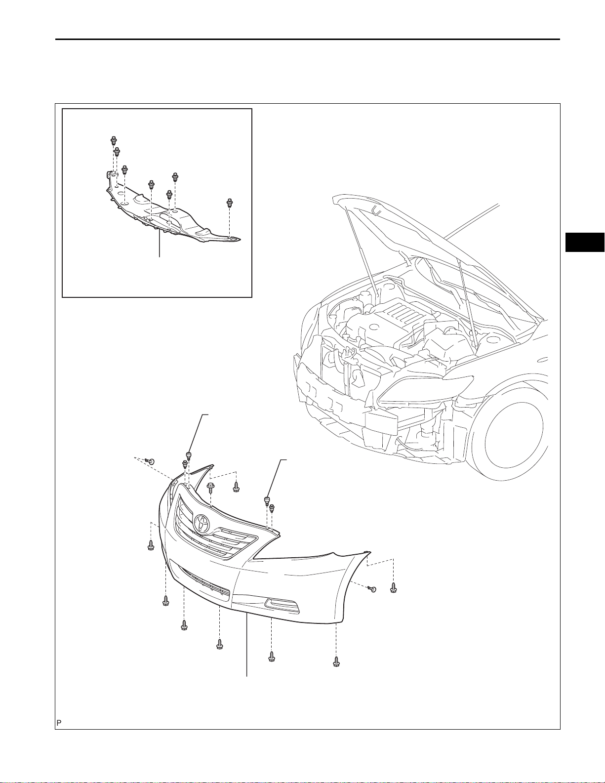
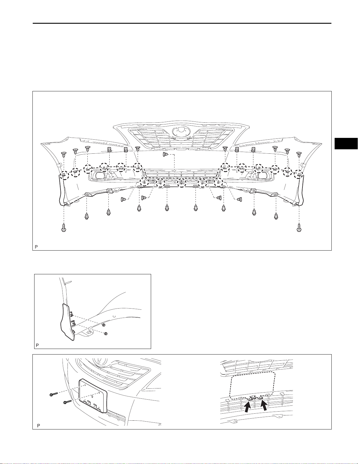
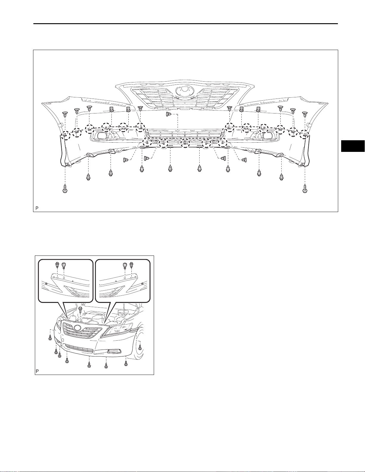
COMPONENTS
for 2GR-FE:
COOL AIR INTAKE DUCT SEAL
EXTERIOR – FRONT BUMPER
ET–1
ET
RADIATOR GRILLE
PROTECTOR
RADIATOR GRILLE
PROTECTOR
FRONT BUMPER ASSEMBLY
B137228E01
ET–2
EXTERIOR – FRONT BUMPER
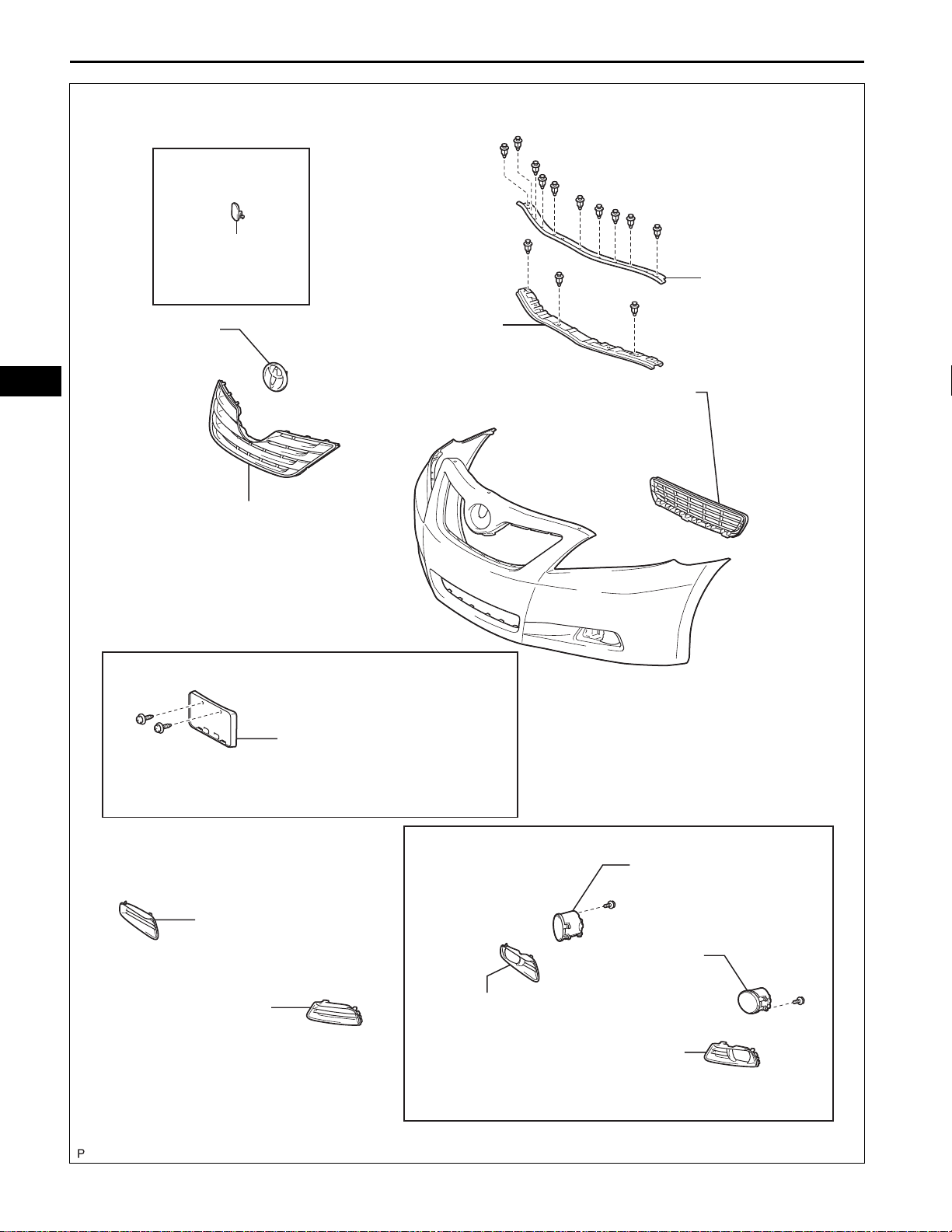
with Cover:
FRONT BUMPER
LOWER COVER
HOOD TO FRONT
END PANEL SEAL
ET
RADIATOR GRILLE
EMBLEM
RADIATOR GRILLE
with Bracket:
FRONT BUMPER
UPPER RETAINER
LOWER RADIATOR GRILLE
FRONT BUMPER EXTENSION
MOUNTING BRACKET
FRONT BUMPER
HOLE COVER RH
FRONT BUMPER
HOLE COVER LH
with Fog light:
FOG LIGHT
ASSEMBLY RH
FOG LIGHT
ASSEMBLY LH
FRONT BUMPER
HOLE COVER RH
FRONT BUMPER
HOLE COVER LH
B137744E01
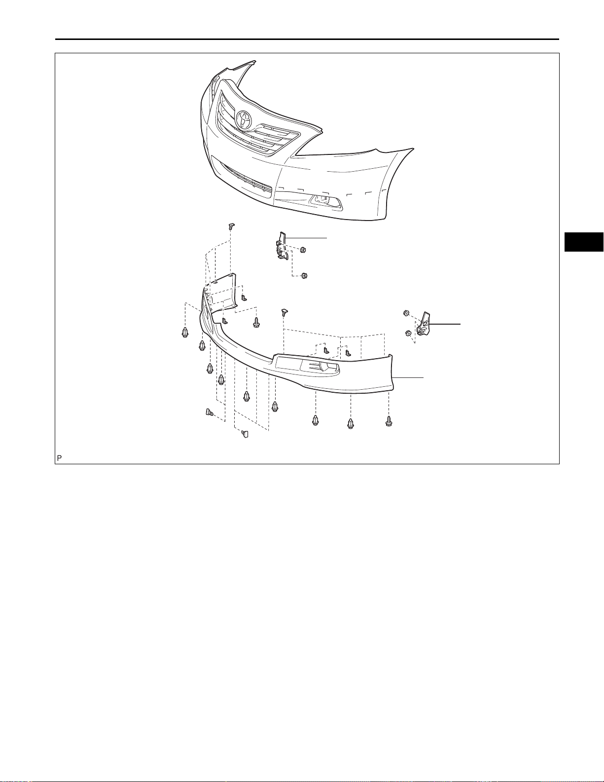
with Front Spoiler:
EXTERIOR – FRONT BUMPER
ET–3
FRONT BUMPER
EXTENSION RH
ET
FRONT BUMPER
EXTENSION LH
FRONT SPOILER
B137745E01
ET–4
EXTERIOR – FRONT BUMPER
ET
FRONT BUMPER
SIDE RETAINER RH
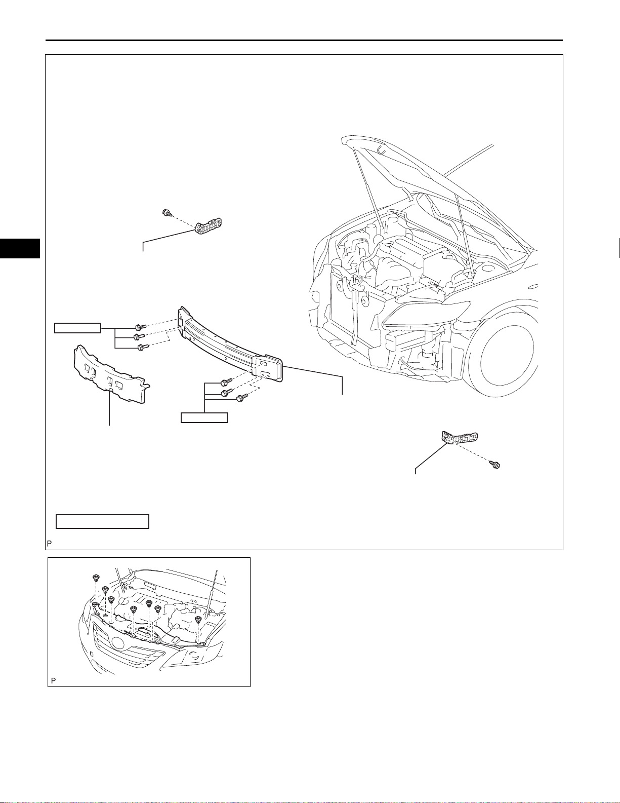
34 (347, 25)
FRONT BUMPER
ENERGY ABSORBER
N*m (kgf*cm, ft.*lbf)
34 (347, 25)
: Specified torque
FRONT BUMPER REINFORCEMENT
SUB-ASSEMBLY
FRONT BUMPER
SIDE RETAINER LH
B137743E01
B138886
REMOVAL
1. REMOVE COOL AIR INTAKE DUCT SEAL (for 2GRFE)
(a) Remove the 7 clips and cool air intake duct seal.
EXTERIOR – FRONT BUMPER
ET–5
Protective Tape
B140157E01
90q
B138884E01
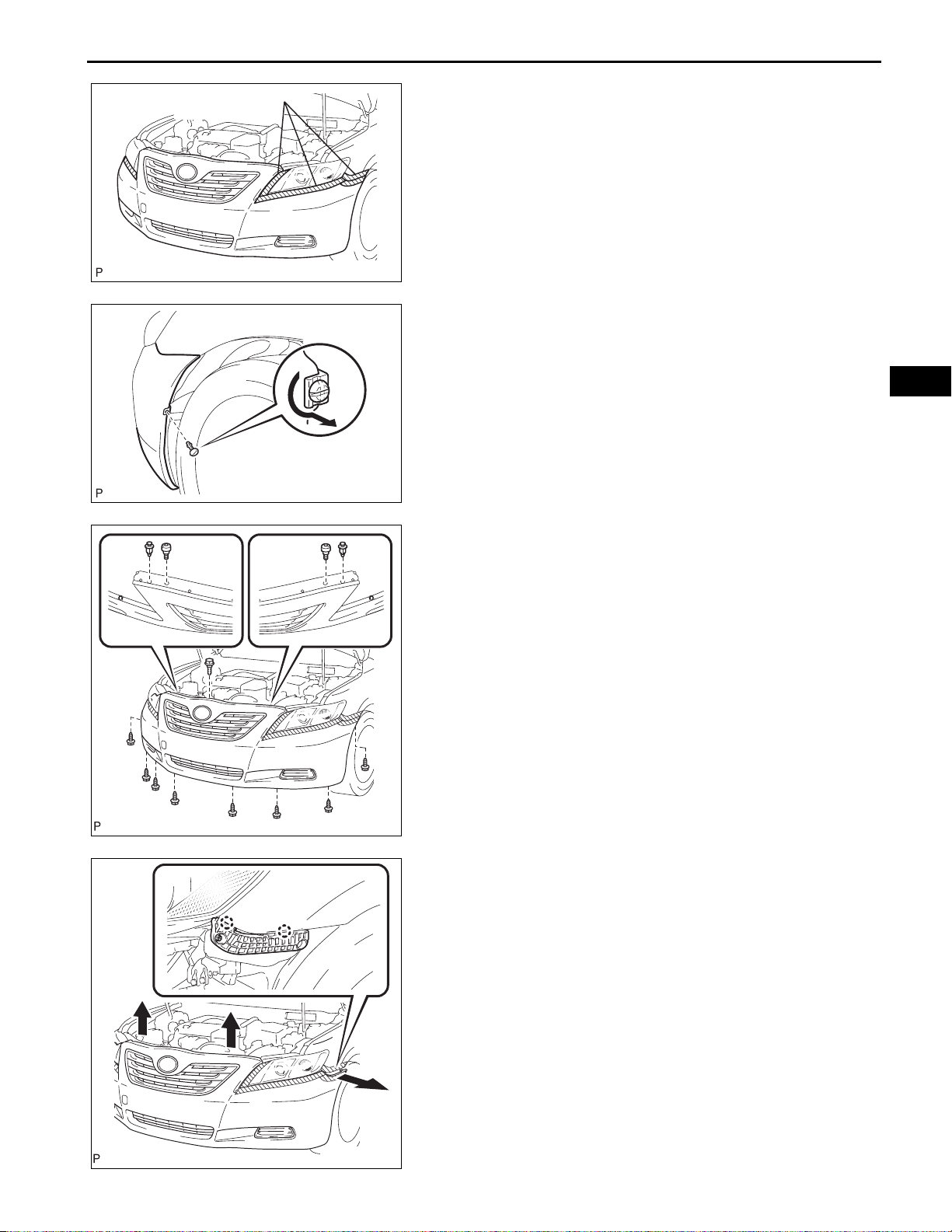
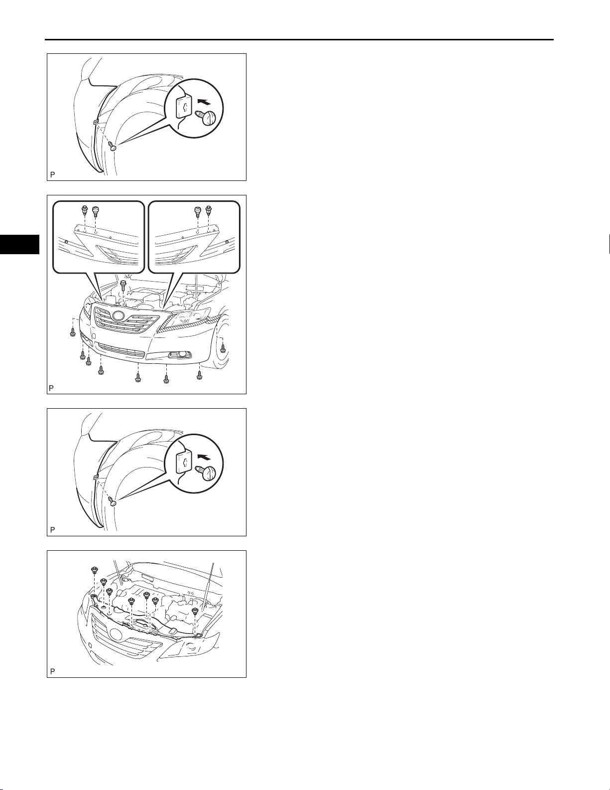
2. REMOVE FRONT BUMPER ASSEMBLY (w/o Fog
Light)
(a) Put protective tape around the front bumper
assembly.
(b) Using a screwdriver, turn the pin 90 degrees and
remove the pin hold clip.
HINT:
Use the same procedures for the RH side and LH
side.
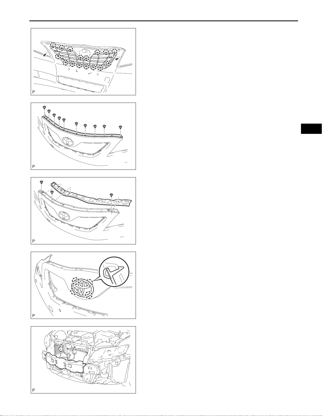
(c) Remove the 8 screws, 2 clips, 2 radiator grille
protectors and bolt.
ET
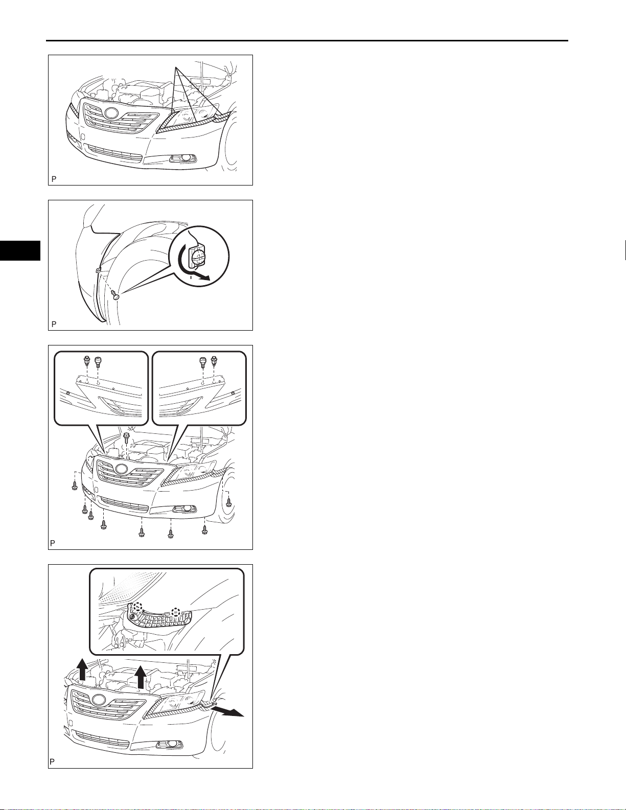
B140155
B140158
(d) Disengage the 2 claws and disconnect the front
bumper assembly as shown in the illustration.
HINT:
Use the same procedures for the RH side and LH
side.
(e) Remove the front bumper assembly.
ET–6
EXTERIOR – FRONT BUMPER
ET
Protective Tape
B138887E01
90q
B138884E01
3. REMOVE FRONT BUMPER ASSEMBLY (w/ Fog
Light)
(a) Put protective tape around the front bumper
assembly.
(b) Using a screwdriver, turn the pin 90 degrees and
remove the pin hold clip.
HINT:
Use the same procedures for the RH side and LH
side.
(c) Remove the 8 screws, 2 clips, 2 radiator grille
protectors and bolt.
B137230
B137231
(d) Disengage the 2 claws and disconnect the front
bumper assembly as shown in the illustration.
HINT:
Use the same procedures for the RH side and LH
side.
(e) Disconnect each connector, and then remove the
front bumper assembly.
EXTERIOR – FRONT BUMPER
DISASSEMBLY
1. REMOVE FOG LIGHT ASSEMBLY LH (w/ Fog Light)
(See page LI-79)
2. REMOVE FOG LIGHT ASSEMBLY RH (w/ Fog Light)
3. REMOVE FRONT SPOILER (w/ Front Spoiler)
(a) Remove the 2 screws and 25 clips.
ET–7
ET
B137753
B137739
(b) Disengage the 17 claws and remove the front
spoiler.
4. REMOVE FRONT BUMPER EXTENSION LH (w/ Front
Spoiler)
(a) Remove the 2 nuts and front bumper extension LH.
5. REMOVE FRONT BUMPER EXTENSION RH (w/ Front
Spoiler)
6. REMOVE FRONT BUMPER EXTENSION MOUNTING
BRACKET (w/ Bracket)
(a) Remove the 2 screws.
B137741E01
ET
ET–8
EXTERIOR – FRONT BUMPER
(b) Disengage the 2 claws and remove the front
bumper extension mounting bracket.
7. REMOVE FRONT BUMPER LOWER COVER (w/
Cover)
(a) Disengage the 2 claws and remove the front
bumper lower cover.
B137730
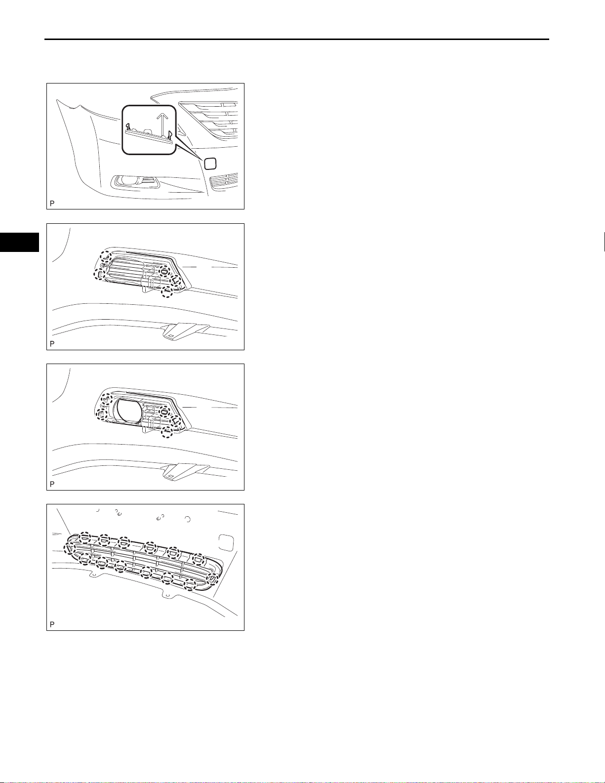
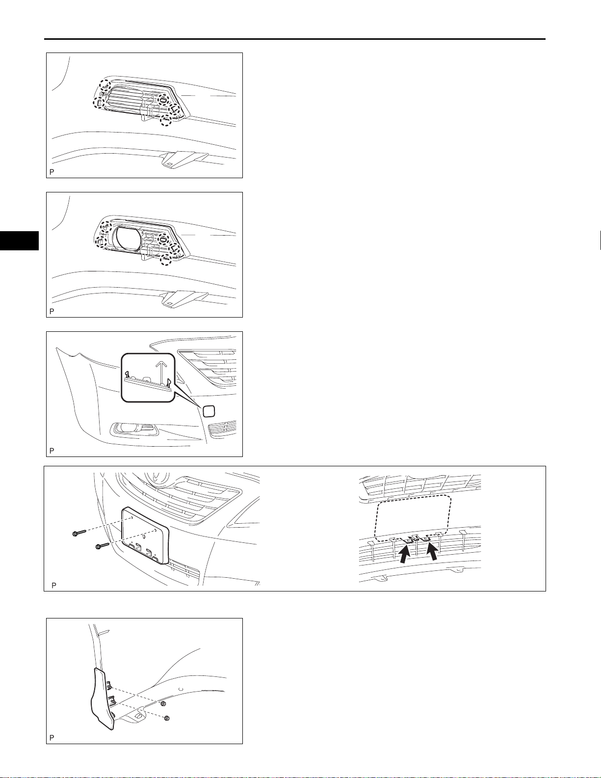
8. REMOVE FRONT BUMPER HOLE COVER LH (w/o
Fog Light)
(a) Disengage the 5 claws and remove the front
bumper hole cover LH.
9. REMOVE FRONT BUMPER HOLE COVER RH (w/o
Fog Light)
B137732
B137733
B137731
10. REMOVE FRONT BUMPER HOLE COVER LH (w/ Fog
Light)
(a) Disengage the 5 claws and remove the front
bumper hole cover LH.
11. REMOVE FRONT BUMPER HOLE COVER RH (w/ Fog
Light)
12. REMOVE LOWER RADIATOR GRILLE
(a) Disengage the 14 claws and remove the lower
radiator grille.
EXTERIOR – FRONT BUMPER
13. REMOVE RADIATOR GRILLE
(a) Remove the 2 screws.
(b) Disengage the 16 claws and remove the radiator
grille.
B137232
14. REMOVE HOOD TO FRONT END PANEL SEAL
(a) Remove the 10 clips and hood to front end panel
seal.
B137233
ET–9
ET
B137234
B137235
15. REMOVE FRONT BUMPER UPPER RETAINER
(a) Remove the 3 clips and front bumper upper retaine r.
16. REMOVE RADIATOR GRILLE EMBLEM
(a) Disengage the 4 claws and remove the radiator
grille emblem.
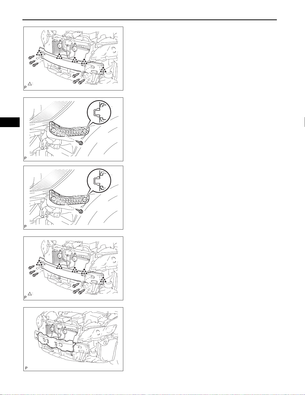
17. REMOVE FRONT BUMPER ENERGY ABSORBER
(a) Remove the front bumper energy absorber from the
front bumper reinforcement sub-assembly.
B137728
ET–10
EXTERIOR – FRONT BUMPER
18. REMOVE FRONT BUMPER REINFORCEMENT SUBASSEMBLY
(a) Disengage each clamp.
(b) Remove the 6 bolts and front bumper reinforcement
sub-assembly.
ET
Clamp
B137729E01
19. REMOVE FRONT BUMPER SIDE RETAINER LH
(a) Remove the screw.
(b) Disengage the claw and remove the front bumper
side retainer LH.
20. REMOVE FRONT BUMPER SIDE RETAINER RH
B137727
REASSEMBLY
1. INSTALL FRONT BUMPER SIDE RETAINER LH
(a) Engage the claw and install the front bumper side
retainer LH.
(b) Install the screw.
2. INSTALL FRONT BUMPER SIDE RETAINER RH
B137727
Clamp
3. INSTALL FRONT BUMPER REINFORCEMENT SUBASSEMBLY
(a) Install the front bumper reinforcement sub-assembly
with the 6 bolts.
Torque: 34 N*m (347 kgf*cm, 25 ft.*lbf)
(b) Engage each clamp.
B137729E01
4. INSTALL FRONT BUMPER ENERGY ABSORBER
(a) Install the front bumper energy absorber to the front
bumper reinforcement sub-assembly.
B137728

EXTERIOR – FRONT BUMPER
5. INSTALL RADIATOR GRILLE EMBLEM
(a) Engage the 4 claws and install the radiator grille
emblem.
B137235
6. INSTALL FRONT BUMPER UPPER RETAINER
(a) Install the front bumper upper retainer with the 3
clips.
B137234
ET–11
ET
B137233
B137232
7. INSTALL HOOD TO FRONT END PANEL SEAL
(a) Apply new double-sided tape to the hood to front
end panel seal.
(b) Remove the release paper from the hood to front
end panel seal.
(c) Install the hood to front end panel seal with the 10
clips.
8. INSTALL RADIATOR GRILLE
(a) Engage the 16 claws and install the radiator grille.
(b) Install the 2 screws.
9. INSTALL LOWER RADIATOR GRILLE
(a) Engage the 14 claws and install the lower radiator
grille.
B137731
ET
ET–12
EXTERIOR – FRONT BUMPER
10. INSTALL FRONT BUMPER HOLE COVER LH (w/o
Fog Light)
(a) Engage the 5 claws and install the front bumper
hole cover LH.
11. INSTALL FRONT BUMPER HOLE COVER RH (w/o
Fog Light)
B137732
12. INSTALL FRONT BUMPER HOLE COVER LH (w/ Fog
Light)
(a) Engage the 5 claws and install the front bumper
hole cover LH.
13. INST ALL FRONT BUMPER HOLE COVER RH (w/ Fog
Light)
B137733
B137730
14. INSTALL FRONT BUMPER LOWER COVER (w/
Cover)
(a) Engage the 2 claws and install the front bumper
lower cover.
15. INSTALL FRONT BUMPER EXTENSION MOUNTING
BRACKET (w/ Bracket)
(a) Engage the 2 claws and install the front bumper
extension mounting bracket.
B137741E01
(b) Install the 2 screws.
B137753
16. INSTALL FRONT BUMPER EXTENSION LH (w/ Front
Spoiler)
(a) Install the front bumper extension LH with the 2
nuts.
17. INSTALL FRONT BUMPER EXTENSION RH (w/ Front
Spoiler)
EXTERIOR – FRONT BUMPER
18. INSTALL FRONT SPOILER (w/ Front Spoiler)
(a) Engage the 17 claws and install the front spoiler.
ET–13
ET
B140155
B137739
(b) Install the 25 clips and 2 screws.
19. INSTALL FOG LIGHT ASSEMBLY LH (w/ Fog Light)
(See page LI-82)
20. INSTALL FOG LIGHT ASSEMBLY RH (w/ Fog Light)
INSTALLATION
1. INSTALL FRONT BUMPER ASSEMBLY (w/o Fog
Light)
(a) Engage each claw .
(b) Install the front bumper assembly with the 8 screws,
2 clips, 2 radiator grille protectors and bolt.
ET
ET–14
EXTERIOR – FRONT BUMPER
(c) Install the pin hold clip.
HINT:
Use the same procedures for the RH side and LH
side.
B137229
2. INSTALL FRONT BUMPER ASSEMBLY (w/ Fog Light)
(a) Connect each connector.
(b) Engage each claw.
(c) Install the front bumper assembly with the 8 screws,
2 clips, 2 radiator grille protectors and bolt.
B137230
B137229
B138886
(d) Install the pin hold clip.
HINT:
Use the same procedures for the RH side and LH
side.
3. INSTALL COOL AIR INTAKE DUCT SEAL (for 2GRFE)
(a) Install the cool air intake duct seal with the 7 clips.
4. VEHICLE PREPARATION FOR FOG LIGHT AIMING
(w/ Fog Light) (See page LI-79)
5. PREPARATION FOR FOG LIGHT AIMING (w/ Fog
Light) (See page LI-80)
6. INSPECT FOG LIGHT AIMING (w/ Fog Light) (See
page LI-81)
7. ADJUST FOG LIGHT AIMING (w/ Fog Light) (See
page LI-82)
BODYEXTERIOR
REAR BUMPER
COMPONENTS
EXTERIOR – REAR BUMPER
ET–15
ET
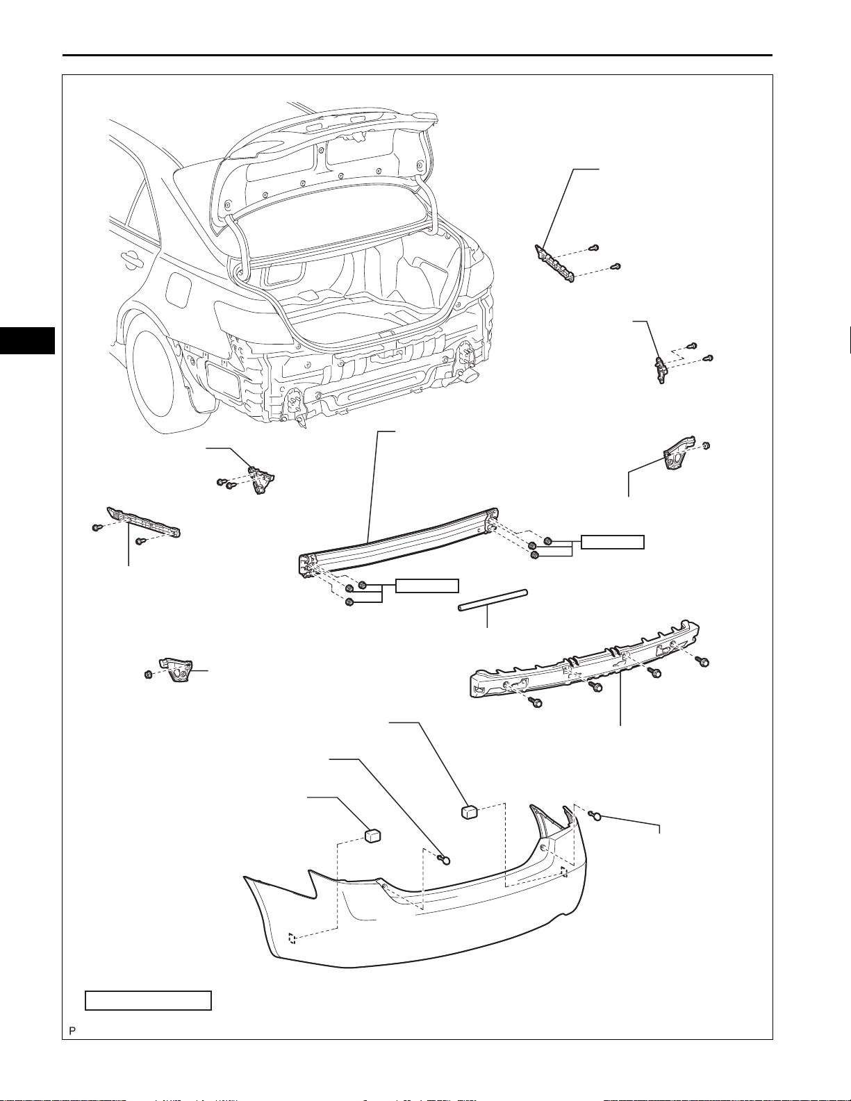
REAR BUMPER ASSEMBLY
with Rear Lower Spoiler:
REAR BUMPER ASSEMBLY
REAR FLOOR BOARD
CLIP
CLIP
NUT
B137224E01
ET
ET–16
REAR BUMPER
SIDE RETAINER LH
EXTERIOR – REAR BUMPER
REAR BUMPER
SIDE SUPPORT RH
REAR BUMPER
SIDE RETAINER RH
REAR BUMPER REINFORCEMENT
SUB-ASSEMBLY
REAR BUMPER
SIDE SUPPORT LH
REAR BUMPER PLATE LH
REAR BUMPER PAD
68 (693, 50)
REAR BUMPER BAR
WHEEL HOUSE REINFORCEMENT LH
REAR BUMPER PAD
WHEEL HOUSE REINFORCEMENT RH
68 (693, 50)
REAR BUMPER ENERGY ABSORBER
REAR BUMPER PLATE RH
N*m (kgf*cm, ft.*lbf)
: Specified torque
B137225E01
with Rear Lower Spoiler:
EXTERIOR – REAR BUMPER
REAR BUMPER
EXTENSION RH
ET–17
ET
REAR BUMPER
EXTENSION LH
Protective Tape
REAR LOWER SPOILER
B140152E01
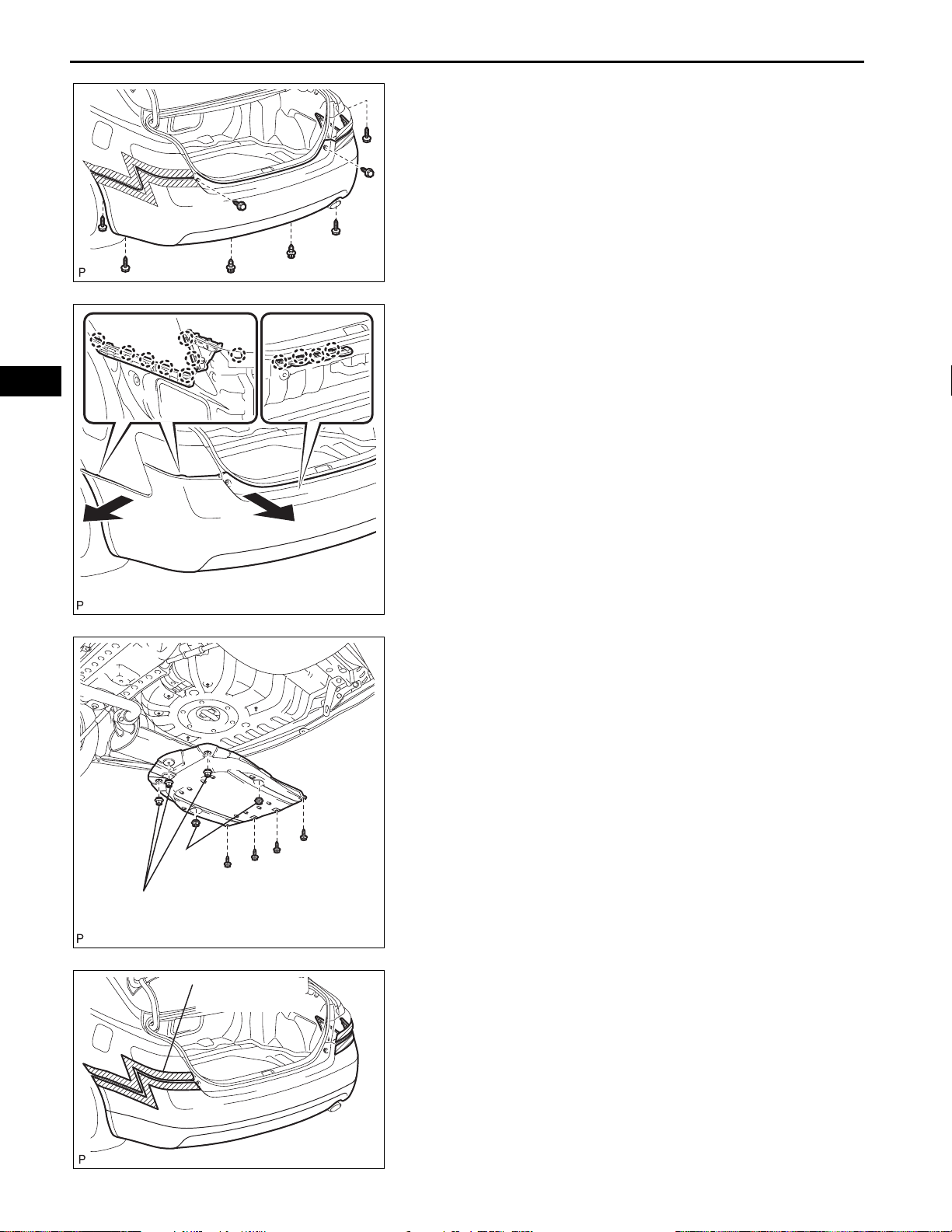
REMOVAL
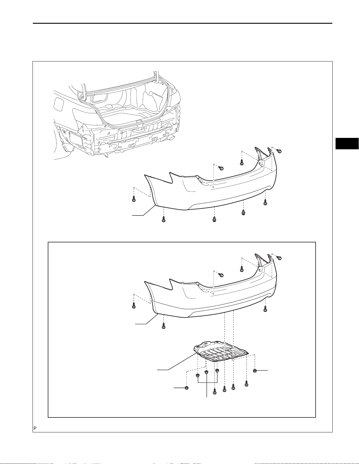
1. REMOVE REAR BUMPER ASSEMBLY (w/o Rear
Lower Spoiler)
(a) Put protective tape around the rear bumper
assembly.
B137211E01
(b) Using a screwdriver, open the 2 rear bumper plates.
HINT:
Tape the screwdriver tip before use.
B137212
ET
ET–18
EXTERIOR – REAR BUMPER
(c) Remove the 6 screws and 2 clips.
B137214
(d) Disengage the 12 claws and disconnect the rear
bumper assembly as shown in the illustration.
HINT:
Use the same procedures for the RH side and LH
side.
(e) Remove the rear bumper assembly.
Nut
Clip
Protective Tape
B137215
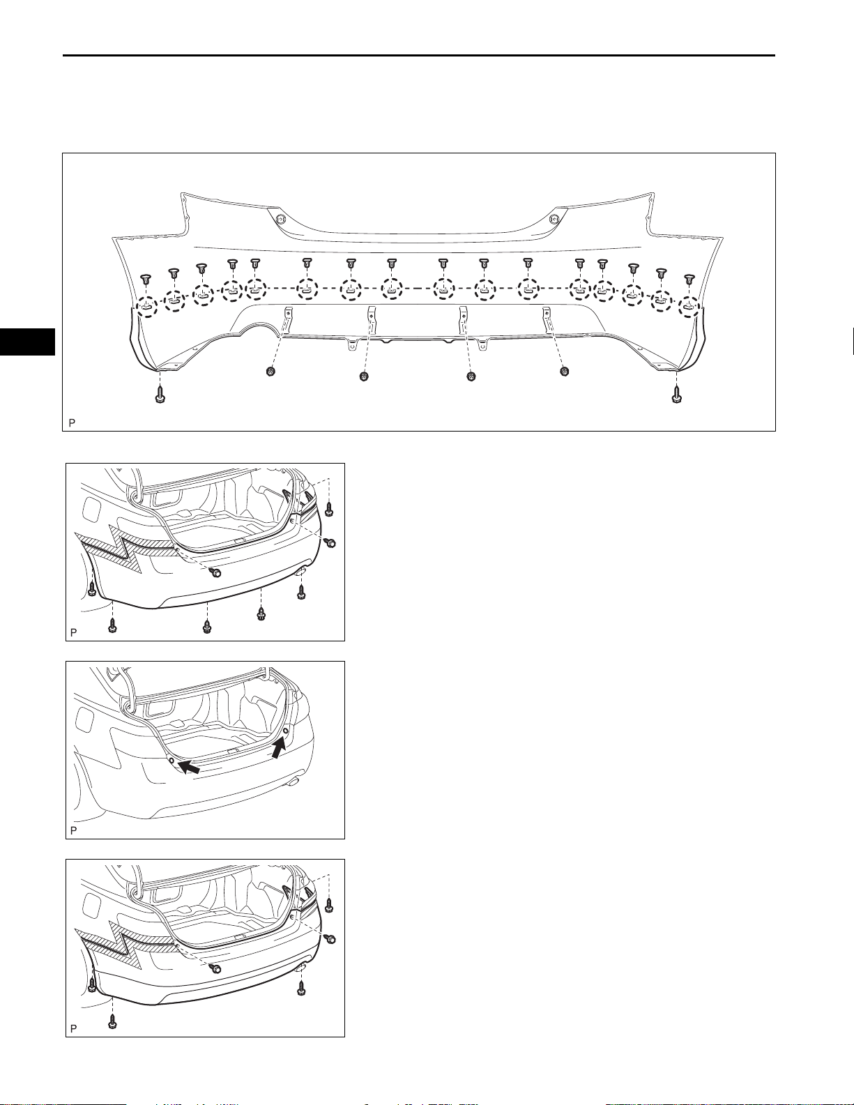
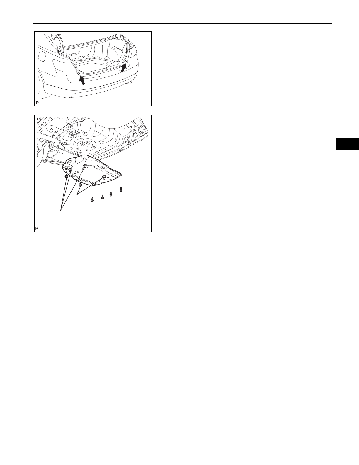
2. REMOVE REAR FLOOR BOARD (w/ Rear Lower
Spoiler)
(a) Remove the 4 screws, 2 clips, 3 nuts and rear floor
board.
B138885E01
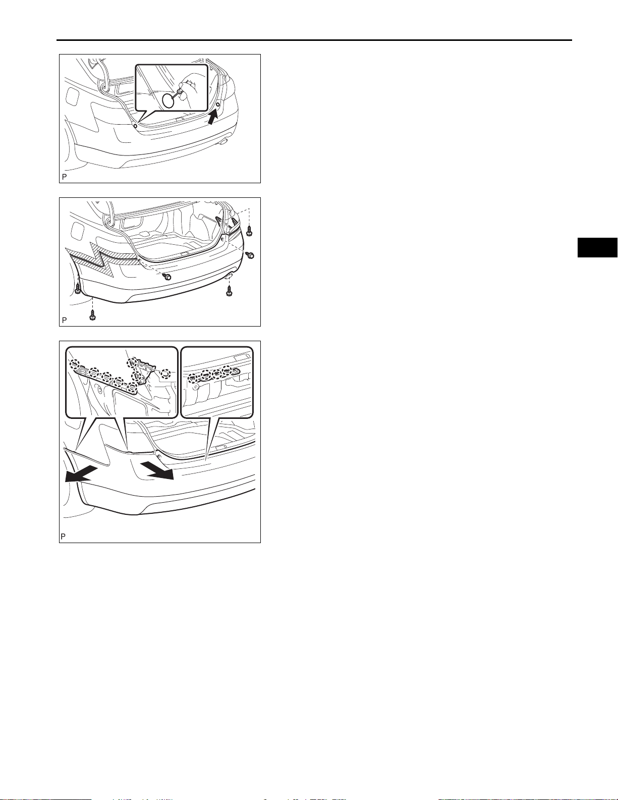
3. REMOVE REAR BUMPER ASSEMBLY (w/ Rear Lower
Spoiler)
(a) Put protective tape around the rear bumper
assembly.
B146330E01
EXTERIOR – REAR BUMPER
(b) Using a screwdriver, open the 2 rear bumper plates.
HINT:
Tape the screwdriver tip before use.
B146331
(c) Remove the 6 screws.
B140154
ET–19
ET
B146332
(d) Disengage the 12 claws and disconnect the rear
bumper assembly as shown in the illustration.
HINT:
Use the same procedures for the RH side and LH
side.
(e) Remove the rear bumper assembly.
ET
ET–20
EXTERIOR – REAR BUMPER
DISASSEMBLY
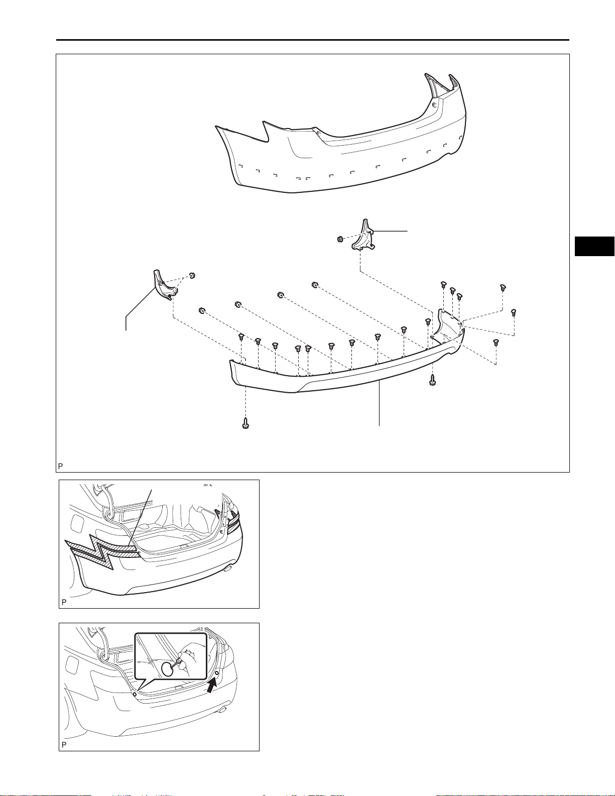
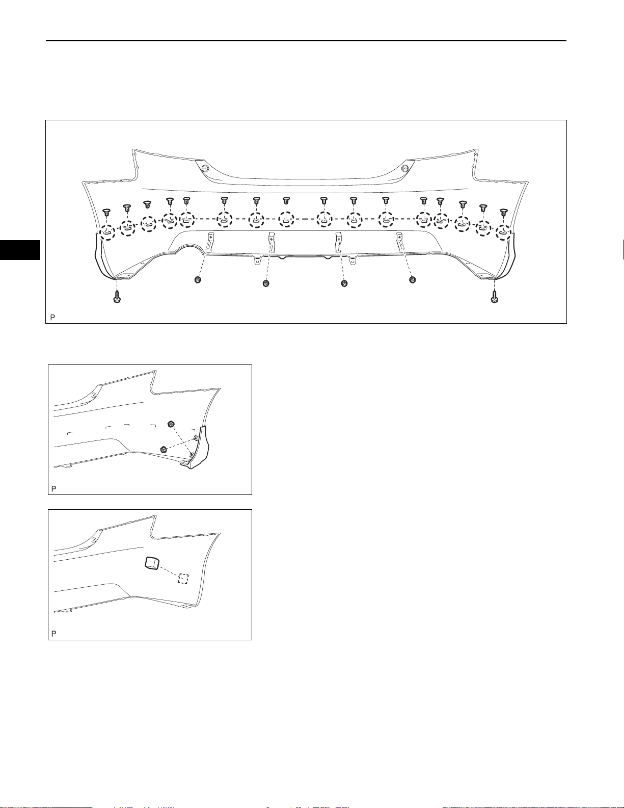
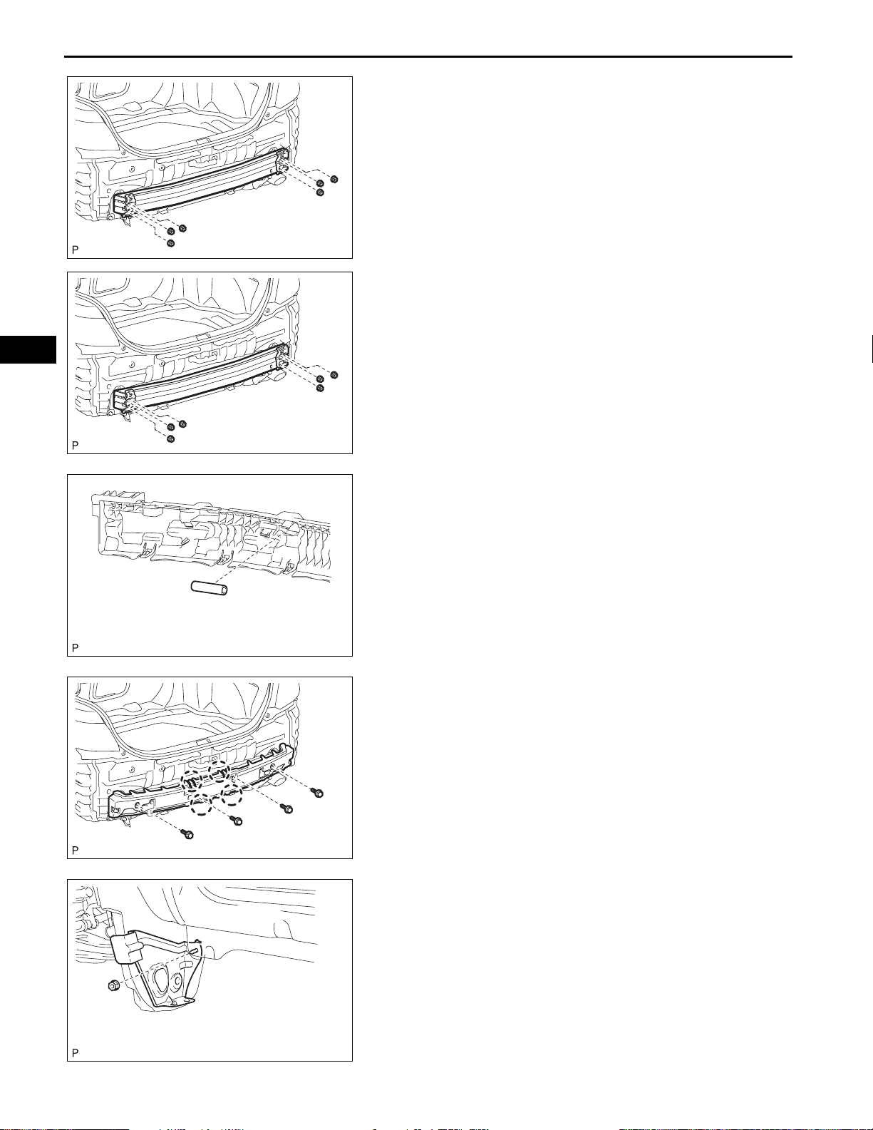
1. REMOVE REAR LOWER SPOILER (w/ Rear Lower
Spoiler)
(a) Remove the 2 screws, 4 nuts and 16 clips.
B137223
B137222
B146333
(b) Disengage the 16 claws and remove the rear lower
spoiler.
2. REMOVE REAR BUMPER EXTENSION LH (w/ Rear
Lower Spoiler)
(a) Remove the 2 nuts and rear bumper extension LH.
3. REMOVE REAR BUMPER EXTENSION RH (w/ Rear
Lower Spoiler)
4. REMOVE REAR BUMPER PLATE LH
5. REMOVE REAR BUMPER PLATE RH
6. REMOVE REAR BUMPER PAD
(a) Remove the rear bumper pad.
HINT:
Use the same procedures for the RH side and LH
side.
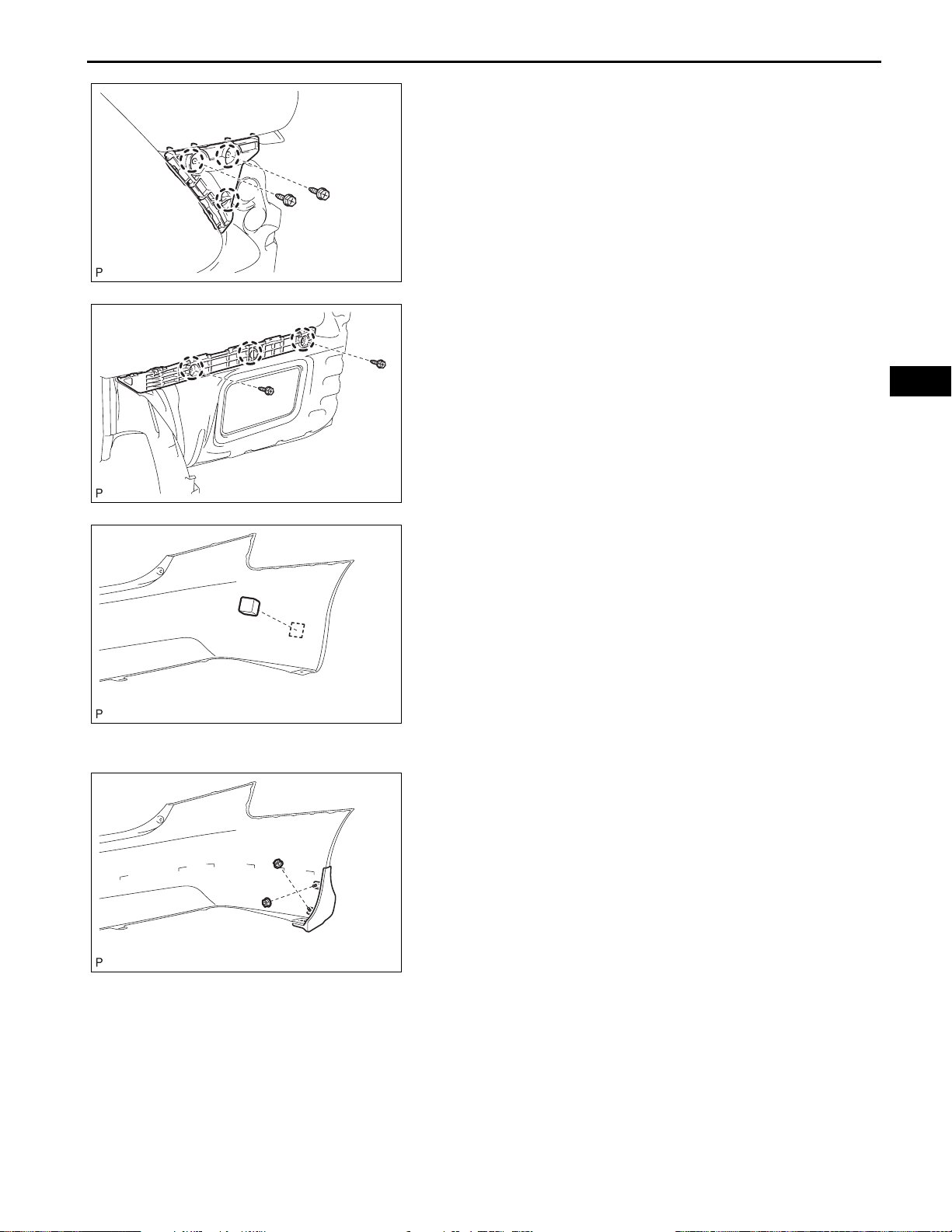
EXTERIOR – REAR BUMPER
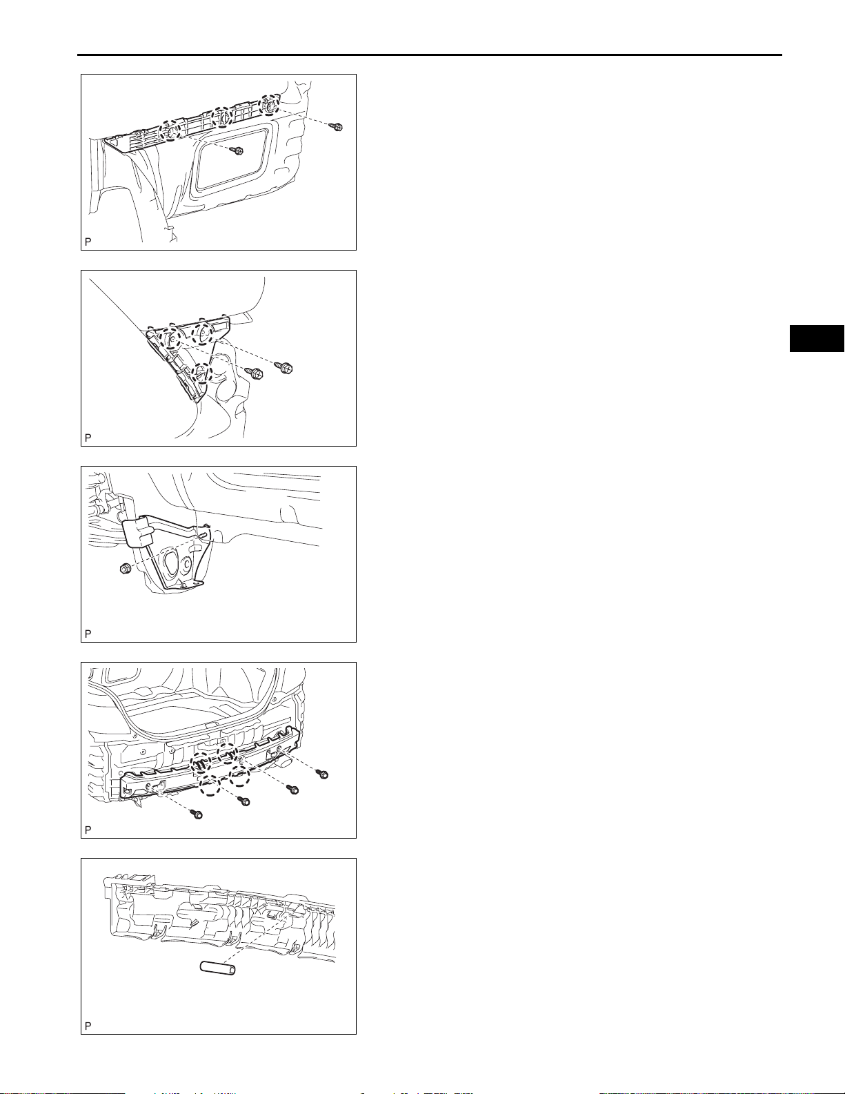
7. REMOVE REAR BUMPER SIDE SUPPORT LH
(a) Remove the 2 screws.
(b) Disengage the 3 claws and remove the rear bumper
side support LH.
8. REMOVE REAR BUMPER SIDE SUPPORT RH
B137219
9. REMOVE REAR BUMPER SIDE RETAINER LH
(a) Remove the 2 screws.
(b) Disengage the 3 claws and remove the rear bumper
side retainer LH.
10. REMOVE REAR BUMPER SIDE RETAINER RH
B137220
ET–21
ET
B137221
B137216
11. REMOVE WHEEL HOUSE REINFORCEMENT LH
(a) Remove the nut and wheel house reinforcement LH.
12. REMOVE WHEEL HOUSE REINFORCEMENT RH
13. REMOVE REAR BUMPER ENERGY ABSORBER
(a) Remove the 4 bolts.
(b) Disengage the 4 claws and remove the rear bumper
energy absorber.
14. REMOVE REAR BUMPER BAR
(a) Remove the rear bumper bar from the rear bumper
energy absorber.
B137218
ET
ET–22
EXTERIOR – REAR BUMPER
15. REMOVE REAR BUMPER REINFORCEMENT SUBASSEMBLY
(a) Remove the 6 nuts and rear bumper reinforcement
sub-assembly.
B137217
REASSEMBLY
1. INSTALL REAR BUMPER REINFORCEMENT SUBASSEMBLY
(a) Install the rear bumper reinforcement sub-assembly
with the 6 nuts.
Torque: 68 N*m (693 kgf*cm, 50 ft.*lbf)
B137217
B137218
B137216
2. INSTALL REAR BUMPER BAR
(a) Install the rear bumper bar on the rear bumper
energy absorber.
3. INSTALL REAR BUMPER ENERGY ABSORBER
(a) Engage the 4 claws and install the rear bumper
energy absorber.
(b) Install the 4 bolts.
4. INSTALL WHEEL HOUSE REINFORCEMENT LH
(a) Install the wheel house reinforcement LH with the
nut.
B137221
5. INSTALL WHEEL HOUSE REINFORCEMENT RH
EXTERIOR – REAR BUMPER
6. INSTALL REAR BUMPER SIDE RETAINER LH
(a) Engage the 3 claws and install the rear bumper side
retainer LH.
(b) Install the 2 screws.
7. INSTALL REAR BUMPER SIDE RETAINER RH
B137220
8. INSTALL REAR BUMPER SIDE SUPPORT LH
(a) Engage the 3 claws and install the rear bumper side
support LH.
(b) Install the 2 screws.
9. INSTALL REAR BUMPER SIDE SUPPORT RH
B137219
ET–23
ET
B146333
B137222
10. INSTALL REAR BUMPER PAD
(a) Apply new double-sided tape to the rear bumper
pad.
(b) Remove the release paper from the rear bumper
pad.
(c) Install the rear bumper pad.
HINT:
Use the same procedures for the RH side and LH
side.
11. INSTALL REAR BUMPER PLATE LH
12. INSTALL REAR BUMPER PLATE RH
13. INSTALL REAR BUMPER EXTENSION LH (w/ Rear
Lower Spoiler)
(a) Install the rear bumper extension LH with the 2 nuts.
14. INSTALL REAR BUMPER EXTENSION RH (w/ Rear
Lower Spoiler)
ET
ET–24
EXTERIOR – REAR BUMPER
15. INSTALL REAR LOWER SPOILER (w/ Rear Lower
Spoiler)
(a) Engage the 16 claws and install the rear lower
spoiler.
B137223
B137214
B137213
(b) Install the 16 clips, 4 nuts and 2 screws.
INSTALLATION
1. INSTALL REAR BUMPER ASSEMBLY (w/o Rear
Lower Spoiler)
(a) Engage each claw.
(b) Install the rear bumper assembly with the 6 screws
and 2 clips.
(c) Install the 2 rear bumper plates.
B140154
2. INST ALL REAR BUMPER ASSEMBLY (w/ Rear Lower
Spoiler)
(a) Engage each claw.
(b) Install the rear bumper assembly with the 6 screws.
EXTERIOR – REAR BUMPER
(c) Install the 2 rear bumper plates.
B147905
3. INSTALL REAR FLOOR BOARD (w/ Rear Lower
Spoiler)
(a) Install the rear floor board with the 3 nuts, 2 clips
and 4 screws.
ET–25
ET
Nut
Clip
B138885E01
BODYEXTERIOR
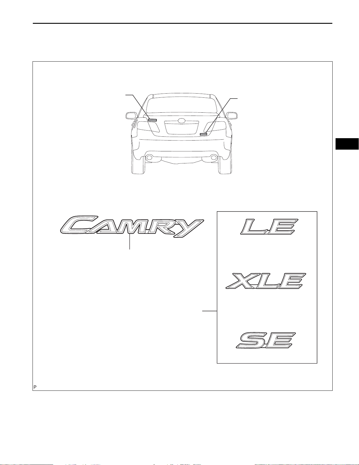
NAME PLATE
COMPONENTS
EXTERIOR – NAME PLATE
ET–25
<1>
NO. 2 LUGGAGE COMPARTMENT DOOR
<1>
NAME PLATE
<2>
ET
<2>
NO. 3 LUGGAGE COMPARTMENT DOOR
NAME PLATE
B137020E01

ET–26
EXTERIOR – NAME PLATE
REMOVAL
HINT:
When removing the name plate, heat the vehicle body and
name plate using a heat light.
Heating temperature
Item Temperature
Vehicle Body 40 to 60°C (104 to 140°F)
Name Plate 20 to 30°C (68 to 86°F)
NOTICE:
Do not heat the vehicle body and name plate excessively.
ET
Wooden Blocks
Protective Tape
Wooden Blocks
Protective Tape
B137022E01
B137023E01
1. REMOVE NO. 2 LUGGAGE COMPARTMENT DOOR
NAME PLATE
(a) Put protective tape around the name plate.
(b) Insert a piano wire between the vehicle body and
name plate.
(c) Tie objects that can serve as handles (for example,
wooden blocks) to both wire ends.
(d) Pull the piano wire and scrape off the double-sided
tape that holds the name plate to the vehicle body.
NOTICE:
• If reusing the name plate, take care not to
damage the name plate.
• Be careful not to damage the vehicle body.
(e) Remove the name plate.
2. REMOVE NO. 3 LUGGAGE COMPARTMENT DOOR
NAME PLATE
(a) Put protective tape around the name plate.
(b) Insert a piano wire between the vehicle body and
name plate.
(c) Tie objects that can serve as handles (for example,
wooden blocks) to both wire ends.
(d) Pull the piano wire and scrape off the double-sided
tape that holds the name plate to the vehicle body.
NOTICE:
• If reusing the name plate, take care not to
damage the name plate.
• Be careful not to damage the vehicle body.
(e) Remove the name plate.

EXTERIOR – NAME PLATE
INSTALLATION
HINT:
When installing the name plate, heat the vehicle body and
name plate using a heat light.
Heating temperature
Item Temperature
Vehicle Body 40 to 60°C (104 to 140°F)
Name Plate 20 to 30°C (68 to 86°F)
NOTICE:
Do not heat the vehicle body and name plate excessively.
1. INSTALL NO. 2 LUGGAGE COMPARTMENT DOOR
NAME PLATE
(a) Clean the vehicle body surface.
(1) Using a heat light, heat the vehicle body
surface.
(2) Remove the double-sided tape from the vehicle
body.
(3) Wipe off any tape adhesive residue with
cleaner.
(b) Clean the name plate. (If reusing the name plate)
(1) Using a heat light, heat the name plate.
(2) Remove the double-sided tape from the name
plate.
(3) Wipe off any tape adhesive residue with
cleaner.
(4) Apply new double-sided tape to the name
plate.
(c) Install the name plate.
ET–27
ET
16.0 mm
(0.630 in.)
8.1 mm
(0.319 in.)
5.5 mm
(0.217 in.)
(1) Using a heat light, heat the vehicle body and
name plate.
(2) Remove the release paper from the name
plate.
HINT:
After removing the release paper, keep the
exposed adhesive free from foreign matter.
(3) Install the name plate.
B137027E01

ET
ET–28
EXTERIOR – NAME PLATE
2. INSTALL NO. 3 LUGGAGE COMPARTMENT DOOR
NAME PLATE
(a) Clean the vehicle body surface.
(1) Using a heat light, heat the vehicle body
surface.
(2) Remove the double-sided tape from the vehicle
body.
(3) Wipe off any tape adhesive residue with
cleaner.
(b) Clean the name plate. (If reusing the name plate)
(1) Using a heat light, heat the name plate.
(2) Remove the double-sided tape from the name
plate.
(3) Wipe off any tape adhesive residue with
cleaner.
(4) Apply new double-sided tape to the name
plate.
(c) Install the name plate.
(1) Using a heat light, heat the vehicle body and
name plate.
(2) Remove the release paper from the name
plate.
HINT:
After removing the release paper, keep the
exposed adhesive free from foreign matter.
(3) Install the name plate.
For name plate LE:
66.8 mm
(2.630 in.)
134.7 mm
(5.303 in.)
64.3 mm
(2.532 in.)
B137028E01
For name plate XLE:

EXTERIOR – NAME PLATE
ET–29
162.2 mm
(6.386 in.)
69.6 mm
(2.740 in.)
66.9 mm
(2.634 in.)
For name plate SE:
136.7 mm
(5.382 in.)
66.6 mm
(2.622 in.)
B137029E01
64.3 mm
(2.532 in.)
ET
B137030E01
ET
ET–30
BODYEXTERIOR
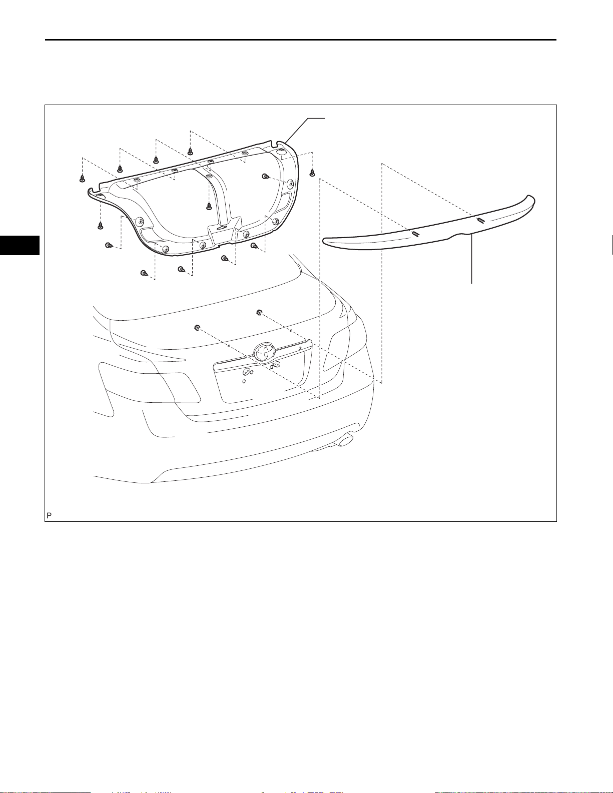
REAR SPOILER
COMPONENTS
EXTERIOR – REAR SPOILER
LUGGAGE COMPARTMENT DOOR COVER
REAR SPOILER
B148216E01

EXTERIOR – REAR SPOILER
REMOVAL
1. REMOVE LUGGAGE COMPARTMENT DOOR COVER
(See page ET-61)
2. REMOVE REAR SPOILER
HINT:
When removing the rear spoiler, heat the vehicle body
and rear spoiler using a heat light.
Heating temperature
Item Temperature
Vehicle Body 40 to 60°C (104 to 140°F)
Spoiler 20 to 30°C (68 to 86°F)
NOTICE:
Do not heat the vehicle body and spoiler
excessively.
ET–31
ET
Protective Tape
B137019E01
B137014
Wooden Blocks
(a) Put protective tape around the rear spoiler.
(b) Remove the 2 nuts.
(c) Insert a piano wire between the vehicle body and
rear spoiler.
(d) Tie objects that can serve as handles (for example,
wooden blocks) to both wire ends.
B137015E01

ET–32
EXTERIOR – REAR SPOILER
(e) Pull the piano wire and scrape off the double-sided
tape that holds the spoiler to the vehicle body.
Double-sided Tape
ET
Clip
Stud Bolt
Clip
Clip
Stud Bolt
Clip
NOTICE:
• If reusing the spoiler , t ake care not to damage
the spoiler.
• Be careful not to damage the vehicle body.
(f) Disengage the 4 clips and remove the rear spoiler.
B137016E01

EXTERIOR – REAR SPOILER
INSTALLATION
1. INSTALL REAR SPOILER
HINT:
When installing the spoiler, heat the vehicle body and
spoiler using a heat light.
Heating temperature
Item Temperature
Vehicle Body 40 to 60°C (104 to 140°F)
Spoiler 20 to 30°C (68 to 86°F)
NOTICE:
Do not heat the vehicle body and rear spoiler
excessively.
(a) Clean the vehicle body surface.
(1) Using a heat light, heat the vehicle body
surface.
(2) Remove the double-sided tape from the vehicle
body.
(3) Wipe off any tape adhesive residue with
cleaner.
(b) Clean the rear spoiler. (If reusing the rear spoiler)
(1) Using a heat light, heat the rear spoiler.
(2) Remove the double-sided tape from the rear
spoiler.
(3) Wipe off any tape adhesive residue with
cleaner.
(4) Apply new double-sided tape to the rear
spoiler.
ET–33
ET
Double-sided Tape
1.2 mm
(0.047 in.)
B137017E01

ET
ET–34
EXTERIOR – REAR SPOILER
(c) Install the rear spoiler.
(1) Using a heat light, heat the vehicle body and
rear spoiler.
(2) Remove the release paper from the rear
spoiler.
HINT:
After removing the release paper, keep the
exposed adhesive free from foreign matter.
(3) Engage the 4 clips and install the rear spoiler
B137018
2. INSTALL LUGGAGE COMPARTMENT DOOR COVER
(See page ET-64)
with the 2 nuts.

EXTERIOR – FRONT DOOR BELT MOULDING
BODYEXTERIOR
FRONT DOOR BELT MOULDING
COMPONENTS
FRONT DOOR BELT
MOULDING ASSEMBLY
ET–33
OUTER REAR VIEW
MIRROR ASSEMBLY
ET
8.0 (80, 71 in.*lbf)
FRONT DOOR INNER GLASS
WEATHERSTRIP
FRONT DOOR INSIDE
HANDLE BEZEL PLUG
FRONT DOOR LOWER FRAME
BRACKET GARNISH
FRONT DOOR TRIM BOARD
SUB-ASSEMBLY
ASSIST GRIP COVER
N*m (kgf*cm, ft.*lbf)
COURTESY LIGHT
ASSEMBLY
: Specified torque
B137749E01

ET
ET–34
Protective Tape
EXTERIOR – FRONT DOOR BELT MOULDING
REMOVAL
1. REMOVE FRONT DOOR LOWER FRAME BRACKET
GARNISH (See page ED-14)
2. REMOVE FRONT DOOR INSIDE HANDLE BEZEL
PLUG (See page ED-14)
3. REMOVE ASSIST GRIP COVER (See page ED-15)
4. REMOVE COURTESY LIGHT ASSEMBLY (See page
ED-15)
5. REMOVE FRONT DOOR TRIM BOARD SUBASSEMBLY (See page ED-15)
6. REMOVE FRONT DOOR INNER GLASS
WEATHERSTRIP (See page ED-16)
7. REMOVE OUTER REAR VIEW MIRROR ASSEMBLY
(See page MI-15)
8. REMOVE FRONT DOOR BELT MOULDING
ASSEMBLY
(a) Fully open the front door glass.
(b) Put protective tape around the front door belt
moulding assembly.
B137001E01
B137002
B137002
(c) Using a moulding remover, disengage the 2 clips
and 5 claws, and remove the front door belt
moulding assembly.
HINT:
Tape the remover tip before use.
NOTICE:
Be careful when removing the moulding as there
are claws attached to the front and rear ends of
the moulding.
INSTALLATION
1. INSTALL FRONT DOOR BELT MOULDING
ASSEMBLY
(a) Engage the 2 clips and 5 claws, and install th e fron t
door belt moulding assembly.
2. INSTALL OUTER REAR VIEW MIRROR ASSEMBLY
(See page MI-17)
3. INSTALL FRONT DOOR INNER GLASS
WEATHERSTRIP (See page ED-32)
4. INSTALL FRONT DOOR TRIM BOARD SUBASSEMBLY (See page ED-33)
5. INSTALL COURTESY LIGHT ASSEMBLY (See page
ED-34)

EXTERIOR – FRONT DOOR BELT MOULDING
6. INSTALL ASSIST GRIP COVER (See page ED-34)
7. INSTALL FRONT DOOR INSIDE HANDLE BEZEL
PLUG (See page ED-34)
8. INSTALL FRONT DOOR LOWER FRAME BRACKET
GARNISH (See page ED-34)
ET–35
ET

ET
ET–36
BODYEXTERIOR
EXTERIOR – REAR DOOR BELT MOULDING
REAR DOOR BELT MOULDING
COMPONENTS
REAR DOOR BELT MOULDING
ASSEMBLY
REAR DOOR INNER
GLASS WEATHERSTRIP
NO. 1 DOOR SCUFF PLATE
CLAMP
REAR DOOR INSIDE HANDLE
BEZEL PLUG
DOOR ASSIST GRIP COVER
REAR DOOR TRIM BOARD SUB-ASSEMBLY
B137751E01

EXTERIOR – REAR DOOR BELT MOULDING
REMOVAL
1. REMOVE REAR DOOR INSIDE HANDLE BEZEL
PLUG (See page ED-38)
2. REMOVE DOOR ASSIST GRIP COVER (See page ED-
38)
3. REMOVE REAR DOOR TRIM BOARD SUBASSEMBLY (See page ED-39)
4. REMOVE REAR DOOR INNER GLASS
WEATHERSTRIP (See page ED-40)
ET–37
Protective Tape
B137003E01
B137004
5. REMOVE REAR DOOR BELT MOULDING ASSEMBLY
(a) Fully open the rear door glass.
(b) Put protective tape around the rear door belt
moulding assembly.
(c) Using a moulding remover, disengage the clip and 6
claws, and remove the rear door belt moulding
assembly.
HINT:
Tape the remover tip before use.
NOTICE:
Be careful when removing the moulding as there
are claws attached to the front end of the
moulding.
INSTALLATION
ET
B137004
1. INSTALL REAR DOOR BELT MOULDING ASSEMBLY
(a) Engage the clip and 6 claws, and install the rear
door belt moulding assembly.
2. INSTALL REAR DOOR INNER GLASS
WEATHERSTRIP (See page ED-54)
3. INSTALL REAR DOOR TRIM BOARD SUBASSEMBLY (See page ED-55)
4. INSTALL DOOR ASSIST GRIP COVER (See page ED-
56)
5. INSTALL REAR DOOR INSIDE HANDLE BEZEL
PLUG (See page ED-56)

ET–38
BODYEXTERIOR
EXTERIOR – ROOF DRIP SIDE FINISH MOULDING
ROOF DRIP SIDE FINISH MOULDING
COMPONENTS
ROOF DRIP SIDE FINISH
MOULDING CENTER
ROOF DRIP SIDE FINISH
MOULDING CLIP
ET
ROOF DRIP SIDE FINISH
MOULDING CLIP
Non-reusable part
B135477E01

EXTERIOR – ROOF DRIP SIDE FINISH MOULDING
REMOVAL
1. REMOVE ROOF DRIP SIDE FINISH MOULDING
CENTER
HINT:
When removing the roof drip side finish moulding center,
heat the body and roof drip side finish moulding center
using a heat light.
Heating temperature
Item Temperature
Vehicle Body 40 to 60°C (104 to 140°F)
Moulding 20 to 30°C (68 to 86°F)
NOTICE:
Do not heat the vehicle body and moulding
excessively.
Protective Tape
(a) Put protective tape around the roof drip side finish
moulding center.
ET–39
ET
B135478E01
B135479E01
(b) Using a moulding remover, disengage the 2 clips
and remove the roof drip side finish moulding
center.
NOTICE:
• Do not remove the clips.
• If the clips are damaged or dropped off,
replace them with new ones.
2. REMOVE ROOF DRIP SIDE FINISH MOULDING CLIP
HINT:
Perform the following procedure if replacing the roof drip
side finish moulding clips.
(a) Remove the 2 roof drip side finish moulding clips.
B135480

ET–40
EXTERIOR – ROOF DRIP SIDE FINISH MOULDING
INSTALLATION
1. INSTALL ROOF DRIP SIDE FINISH MOULDING CLIP
NOTICE:
If installing new clips, remove the double-sided tape
remaining where the clips will be installed on the
body and clean the body with a non-residue type
solvent.
ET
2 to 3 mm (0.07 to 0.11 in.)
Bead of Adhesive
A
B
Adhesive
B140153E01
(a) Apply a 2 to 3 mm (0.07 to 0.11 in.) bead of
adhesive (3M DP-105 or equivalent) to new roof drip
side finish moulding clips.
HINT:
Adhesive strength (tensile strength): 13.7 MPa (140
kgf/cm
2
) or more (when the temperature is 23°C)
(b) Install the roof drip side finish moulding clips to the
positions on the roof panel shown in the illustration.
Determine the locations and firmly press and install
the roof drip side finish moulding clips after lightly
rubbing up adhesive (3M DP-105 or equivalent).
C
D
Standard dimension
Area Dimension
A 1.4 mm (0.055 in.)
B 12.4 mm (0.488 in.)
C 1.1 mm (0.043 in.)
D 12.1 mm (0.476 in.)
HINT:
• Initial hardening time: 20 minutes
• Complete hardening time: 48 hours
B136999E01

EXTERIOR – ROOF DRIP SIDE FINISH MOULDING
2. INSTALL ROOF DRIP SIDE FINISH MOULDING
CENTER
(a) Install the roof drip side finish moulding center when
20 minutes or more have elapsed after pressing and
installing the roof drip side finish moulding clips.
Installation Datum
ET–41
ET
B137000E01
NOTICE:
• Install the roof drip side finish moulding
center in the proper direction.
• Set the front clip to the installation datum.
Make sure that the front clip and roof drip
side finish moulding center are fit each other.

ET
ET–42
BODYEXTERIOR
EXTERIOR – ROCKER PANEL MOULDING
ROCKER PANEL MOULDING
COMPONENTS
ROCKER PANEL MOULDING
GROMMET
Non-reusable part
ROCKER PANEL MOULDING
PROTECTOR
B135469E01
REMOVAL
1. REMOVE ROCKER PANEL MOULDING PROTECTOR
(a) Remove the 2 screws and rocker panel moulding
protector.
B135471

EXTERIOR – ROCKER PANEL MOULDING
2. REMOVE ROCKER PANEL MOULDING
(a) Put protective tape around the rocker panel
moulding.
Protective Tape
(b) Remove the 2 screws and grommet.
ET–43
Protective Tape
B135470E01
ET
B135472
B135473
B135475
(c) Remove the screw.
(d) Remove the 7 clips.

ET
ET–44
EXTERIOR – ROCKER PANEL MOULDING
(e) Remove the 2 screws.
B135474
(f) Disengage the 8 clips and remove the rocker panel
moulding.
B135476
B135476
B135474
INSTALLATION
1. INSTALL ROCKER PANEL MOULDING
(a) Engage the 8 clips and install the rocker panel
moulding.
(b) Install the 2 screws.
(c) Install the 7 clips.
B135475

EXTERIOR – ROCKER PANEL MOULDING
(d) Install the screw.
B135473
(e) Install a new grommet and 2 screws.
B135472
ET–45
ET
B135471
2. INSTALL ROCKER PANEL MOULDING PROTECTOR
(a) Install the rocker panel moulding pro tector with the 2
screws.

ET
ET–46
BODYEXTERIOR
EXTERIOR – FRONT DOOR WINDOW FRAME MOULDING
FRONT DOOR WINDOW FRAME MOULDING
COMPONENTS
OUTER REAR VIEW
MIRROR ASSEMBLY
FRONT DOOR BELT
MOULDING ASSEMBLY
8.0 (80, 71 in.*lbf)
FRONT DOOR INNER GLASS
WEATHERSTRIP
FRONT DOOR INSIDE
HANDLE BEZEL PLUG
FRONT DOOR LOWER FRAME
BRACKET GARNISH
FRONT DOOR TRIM BOARD
SUB-ASSEMBLY
ASSIST GRIP COVER
N*m (kgf*cm, ft.*lbf)
COURTESY LIGHT
ASSEMBLY
: Specified torque
B137749E01

EXTERIOR – FRONT DOOR WINDOW FRAME MOULDING
FRONT DOOR UPPER WINDOW
FRAME MOULDING
FRONT DOOR REAR WINDOW
FRAME MOULDING
FRONT DOOR GLASS RUN
ET–47
RIVET
ET
FRONT DOOR GLASS SUB-ASSEMBLY
FRONT DOOR WEATHERSTRIP
BUTYL TAPE
FRONT DOOR INSIDE
HANDLE SUB-ASSEMBLY
FRONT DOOR SERVICE
HOLE COVER
Non-reusable part
FRONT NO. 1 SPEAKER
ASSEMBLY
B137750E01

ET
ET–48
EXTERIOR – FRONT DOOR WINDOW FRAME MOULDING
REMOVAL
1. REMOVE FRONT DOOR LOWER FRAME BRACKET
GARNISH (See page ED-14)
2. REMOVE FRONT DOOR INSIDE HANDLE BEZEL
PLUG (See page ED-14)
3. REMOVE ASSIST GRIP COVER (See page ED-15)
4. REMOVE COURTESY LIGHT ASSEMBLY (See page
ED-15)
5. REMOVE FRONT DOOR TRIM BOARD SUBASSEMBLY (See page ED-15)
6. REMOVE FRONT DOOR INNER GLASS
WEATHERSTRIP (See page ED-16)
7. REMOVE FRONT DOOR INSIDE HANDLE SUBASSEMBLY (See page ED-17)
8. REMOVE FRONT NO. 1 SPEAKER ASSEMBLY (See
page AV-155)
B129816
9. REMOVE OUTER REAR VIEW MIRROR ASSEMBLY
(See page MI-15)
10. REMOVE FRONT DOOR SERVICE HOLE COVER
(See page ED-17)
11. REMOVE FRONT DOOR GLASS SUB-ASSEMBLY
(See page ED-17)
12. REMOVE FRONT DOOR GLASS RUN (See page ED-
19)
13. REMOVE FRONT DOOR WEATHERSTRIP
(a) Using a clip remover, disengage the clip and
remove the front door weatherstrip.
14. REMOVE FRONT DOOR REAR WINDOW FRAME
MOULDING
HINT:
When removing the front door rear window frame
moulding, heat the vehicle body and front door rear
window frame moulding using a heat light.
Heating temperature
Item Temperature
Vehicle Body 40 to 60°C (104 to 140°F)
Moulding 20 to 30°C (68 to 86°F)
NOTICE:
Do not heat the vehicle body and moulding
excessively.
(a) Using a heat light, heat the front door rear window
frame moulding.

EXTERIOR – FRONT DOOR WINDOW FRAME MOULDING
(b) Disengage the clip.
B137005
(c) Using a moulding remover, remove the front door
rear window frame moulding.
ET–49
Double-sided Tape
5 mm (0.20 in.)
B137006E01
B137008E01
ET
15. REMOVE FRONT DOOR UPPER WINDOW FRAME
MOULDING
(a) Put a 4 mm (0.16 in.) drill bit into a drill.
(b) Tape the drill bit without the portion of 5 mm (0.20
in.) from the tip covered.
HINT:
Tape the drill bit to prevent the drill bit from going too
deep.
(c) Lightly press the drill against the rivets, drill off the
flanges of the rivets, and remove the 7 rivets.
NOTICE:
• Pressing the drill too firmly will cause the
rivet to turn and result in the rivet not being
drilled through.
• Do not pry the rivets with the drill, because
this may cause damage to the installation
holes of the rivets or the drill bit.
• Be careful when touching the drilled rivet s as
they may become hot.
(d) Using a vacuum cleaner, remove the rivet fragment s
and shavings from the drilled areas.
(e) Remove the front door upper window frame
moulding from the door frame.

ET–50
EXTERIOR – FRONT DOOR WINDOW FRAME MOULDING
INSTALLATION
1. INSTALL FRONT DOOR UPPER WINDOW FRAME
MOULDING
(a) Install the front door upper window frame moulding
to the door frame.
(b) Using an air riveter or hand riveter with a nose
piece, install the front door upper window frame
moulding with 7 new rivets.
HINT:
If the rivet cannot be cut, pull it once and cut it.
ET
Riveter
Mandrel
Riveter
Riveter
INCORRECT
INCORRECT
INCORRECT
B105049
NOTICE:
• Do not pry the rivet with the riveter, as this
will cause damage to the riveter and mandrel.
B125583E01
• Confirm that the rivets are seated properly
against the moulding. Do not tilt the riveter
when installing the rivet to the moulding. Do
not leave any space between the rivet head
and moulding.
B125584E01
Riveter
INCORRECT
B125585E01
• Do not leave any space between the moulding
and door frame. Firmly hold together the 2
items while installing the rivet.
2. INSTALL FRONT DOOR REAR WINDOW FRAME
MOULDING
HINT:
When installing the front door rear window frame
moulding, heat the vehicle body and front door rear
window frame moulding using a heat light.
Heating temperature
Item Temperature
Vehicle Body 40 to 60°C (104 to 140°F)
Moulding 20 to 30°C (68 to 86°F)

EXTERIOR – FRONT DOOR WINDOW FRAME MOULDING
Double-sided Tape
0.8 mm
(0.032 in.)
ET–51
NOTICE:
Do not heat the vehicle body and front door window
frame moulding excessively.
(a) Clean the vehicle body surface.
(1) Using a heat light, heat the vehicle body
surface.
(2) Remove the double-sided tape from the vehicle
body.
(3) Wipe off any tape adhesive residue with
cleaner.
(b) Clean the front door rear window frame moulding. (If
reusing the front door rear window frame moulding)
(1) Using a heat light, heat the front door rear
window frame moulding.
(2) Remove the double-sided tape from the front
door rear window frame moulding.
(3) Wipe off any tape adhesive residue with
cleaner.
(4) Apply new double-sided tape to the front door
rear window frame moulding.
ET
5.0 mm
(0.197 in.)
B137007E01
(c) Install the front door rear window frame moulding.
(1) Using a heat light, heat the vehicle body and
front door rear window frame moulding.
(2) Remove the release paper from the front door
rear window frame moulding.
HINT:
After removing the release paper, keep the
exposed adhesive free from foreign matter.
B137754
(3) Engage the clip and install the front door rear
window frame moulding.
B137005

ET–52
EXTERIOR – FRONT DOOR WINDOW FRAME MOULDING
3. INSTALL FRONT DOOR WEATHERSTRIP
(a) Engage the clip and install the front door
weatherstrip.
4. INSTALL FRONT DOOR GLASS RUN (See page ED-
30)
5. INSTALL FRONT DOOR GLASS SUB-ASSEMBLY
(See page ED-31)
ET
B129818
6. INST ALL FRONT DOOR SERVICE HOLE COVER (See
page ED-32)
7. INSTALL OUTER REAR VIEW MIRROR ASSEMBLY
(See page MI-17)
8. INSTALL FRONT NO. 1 SPEAKER ASSEMBLY (See
page AV-157)
9. INSTALL FRONT DOOR INSIDE HANDLE SUBASSEMBLY (See page ED-33)
10. INSTALL FRONT DOOR INNER GLASS
WEATHERSTRIP (See page ED-32)
11. INSTALL FRONT DOOR TRIM BOARD SUBASSEMBLY (See page ED-33)
12. INSTALL COURTESY LIGHT ASSEMBLY (See page
ED-34)
13. INSTALL ASSIST GRIP COVER (See page ED-34)
14. INSTALL FRONT DOOR INSIDE HANDLE BEZEL
PLUG (See page ED-34)
15. INSTALL FRONT DOOR LOWER FRAME BRACKET
GARNISH (See page ED-34)

EXTERIOR – REAR DOOR WINDOW FRAME MOULDING
BODYEXTERIOR
REAR DOOR WINDOW FRAME MOULDING
COMPONENTS
REAR DOOR BELT MOULDING
ASSEMBLY
REAR DOOR INNER
GLASS WEATHERSTRIP
ET–53
ET
NO. 1 DOOR SCUFF PLATE
CLAMP
REAR DOOR INSIDE HANDLE
BEZEL PLUG
DOOR ASSIST GRIP COVER
REAR DOOR TRIM BOARD SUB-ASSEMBLY
B137751E01

ET
ET–54
REAR DOOR UPPER WINDOW
FRAME MOULDING
REAR DOOR QUARTER
WINDOW GLASS
EXTERIOR – REAR DOOR WINDOW FRAME MOULDING
RIVET
REAR DOOR FRONT WINDOW
FRAME MOULDING
REAR DOOR WEATHERSTRIP
REAR DOOR LOWER WINDOW
FRAME SUB-ASSEMBLY
REAR DOOR GLASS SUB-ASSEMBLY
REAR DOOR GLASS RUN
BUTYL TAPE
REAR DOOR SERVICE
HOLE COVER
Non-reusable part
REAR DOOR INSIDE HANDLE
SUB-ASSEMBLY
B137752E01

EXTERIOR – REAR DOOR WINDOW FRAME MOULDING
REMOVAL
1. REMOVE REAR DOOR INSIDE HANDLE BEZEL
PLUG (See page ED-38)
2. REMOVE DOOR ASSIST GRIP COVER (See page ED-
38)
3. REMOVE REAR DOOR TRIM BOARD SUBASSEMBLY (See page ED-39)
4. REMOVE REAR DOOR INNER GLASS
WEATHERSTRIP (See page ED-40)
5. REMOVE REAR DOOR INSIDE HANDLE SUBASSEMBLY (See page ED-40)
6. REMOVE REAR DOOR SERVICE HOLE COVER (See
page ED-41)
7. REMOVE REAR DOOR GLASS RUN (See page ED-
42)
8. REMOVE REAR DOOR LOWER WINDOW FRAME
SUB-ASSEMBLY (See page ED-42)
ET–55
ET
B129819
9. REMOVE REAR DOOR QUARTER WINDOW GLASS
(See page ED-43)
10. REMOVE REAR DOOR GLASS SUB-ASSEMBL Y (See
page ED-43)
11. REMOVE REAR DOOR WEATHERSTRIP
(a) Using a clip remover, disengage the clip and
remove the rear door weatherstrip.
12. REMOVE REAR DOOR FRONT WINDOW FRAME
MOULDING
HINT:
When removing the rear door front window frame
moulding, heat the vehicle body and rear door front
window frame moulding using a heat light.
Heating temperature
Item Temperature
Vehicle Body 40 to 60°C (104 to 140°F)
Moulding 20 to 30°C (68 to 86°F)
NOTICE:
Do not heat the vehicle body and moulding
excessively.
(a) Using a heat light, heat the rear door front window
frame moulding.

ET–56
EXTERIOR – REAR DOOR WINDOW FRAME MOULDING
(b) Disengage the clip.
B137009
(c) Using a moulding remover, remove the rear door
front window frame moulding.
ET
Double-sided Tape
5 mm (0.20 in.)
B137010E01
B137012E01
13. REMOVE REAR DOOR UPPER WINDOW FRAME
MOULDING
(a) Put a 4 mm (0.16 in.) drill bit into a drill.
(b) Tape the drill bit without the portion of 5 mm (0.20
in.) from the tip covered.
HINT:
Tape the drill bit to prevent the drill bit from going too
deep.
(c) Lightly press the drill bit against the rivets, drill off
the flanges of the rivets, and remove the 7 rivets.
NOTICE:
• Pressing the drill too firmly will cause the
rivet to turn and result in the rivet not being
drilled through.
• Do not pry the rivets with the drill, as this may
cause damage to the installation holes of the
rivets or the drill bit.
• Be careful when touching the drilled rivets, as
they may become hot.
(d) Using a vacuum cleaner , remove the rivet fragments
and shavings from the drilled areas.
(e) Remove the rear door upper window frame
moulding from the door frame.

EXTERIOR – REAR DOOR WINDOW FRAME MOULDING
INSTALLATION
1. INSTALL REAR DOOR UPPER WINDOW FRAME
MOULDING
(a) Install the rear door upper window frame moulding
to the door frame.
(b) Using an air riveter or hand riveter with a nose
piece, install the rear door upper window frame
moulding with 7 new rivets.
HINT:
If the rivet cannot be cut, pull it once and cut it.
ET–57
Riveter
Mandrel
Riveter
Riveter
INCORRECT
INCORRECT
INCORRECT
B105050
B125583E01
B125584E01
ET
NOTICE:
• Do not pry the rivet with the riveter, as this
will cause damage to the riveter and mandrel.
• Confirm that the rivets are seated properly
against the moulding. Do not tilt the riveter
when installing the rivet to the moulding. Do
not leave any space between the rivet head
and moulding.
Riveter
INCORRECT
B125585E01
• Do not leave any space between the moulding
and door frame. Firmly hold together the 2
items while installing the rivet.
2. INSTALL REAR DOOR FRONT WINDOW FRAME
MOULDING
HINT:
When installing the rear door front window frame
moulding, heat the vehicle body and rear door front
window frame using a heat light.
Heating temperature
Item Temperature
Vehicle Body 40 to 60°C (104 to 140°F)
Moulding 20 to 30°C (68 to 86°F)

ET–58
EXTERIOR – REAR DOOR WINDOW FRAME MOULDING
NOTICE:
Do not heat the vehicle body and rear door window
frame moulding excessively.
(a) Clean the vehicle body surface.
(1) Using a heat light, heat the vehicle body
surface.
(2) Remove the double-sided tape from the vehicle
body.
(3) Wipe off any tape adhesive residue with
cleaner.
ET
Double-sided Tape (A)
0.8 mm
(0.032 in.)
Double-sided Tape (B)
1.2 mm
(0.047 in.)
Double-sided Tape (B)
Double-sided Tape (A)
5.0 mm
(0.197 in.)
5.0 mm
(0.197 in.)
B137011E01
(b) Clean the rear door front window frame moulding. (If
reusing the rear door front window frame moulding)
(1) Using a heat light, heat the rear door front
window frame moulding.
(2) Remove the double-sided tape from the rear
door front window frame moulding.
(3) Wipe off any tape adhesive residue with
cleaner.
(4) Apply new double-sided tape to the rear door
front window frame moulding.
(c) Install the rear door front window frame moulding.
(1) Using a heat light, heat the vehicle body and
rear door front window frame moulding.
(2) Remove the release paper from the rear door
front window frame moulding.
HINT:
After removing the release paper, keep the
exposed adhesive free from foreign matter.
B137755
B137009
(3) Engage the clip and install the rear door front
window frame moulding.

EXTERIOR – REAR DOOR WINDOW FRAME MOULDING
3. INSTALL REAR DOOR WEATHERSTRIP
(a) Engage the clip and install the rear door
weatherstrip.
4. INST ALL REAR DOOR GLASS SUB-ASSEMBLY (See
page ED-52)
5. INSTALL REAR DOOR QUARTER WINDOW GLASS
(See page ED-52)
ET–59
B129820
6. INSTALL REAR DOOR LOWER WINDOW FRAME
SUB-ASSEMBLY (See page ED-52)
7. INSTALL REAR DOOR GLASS RUN (See page ED-52)
8. INSTALL REAR DOOR SERVICE HOLE COVER (See
page ED-53)
9. INSTALL REAR DOOR INSIDE HANDLE SUBASSEMBLY (See page ED-55)
10. INSTALL REAR DOOR INNER GLASS
WEATHERSTRIP (See page ED-54)
11. INSTALL REAR DOOR TRIM BOARD SUBASSEMBLY (See page ED-55)
12. INSTALL DOOR ASSIST GRIP COVER (See page ED-
56)
13. INSTALL REAR DOOR INSIDE HANDLE BEZEL
PLUG (See page ED-56)
ET

ET
ET–60
BODYEXTERIOR
EXTERIOR – LUGGAGE COMPARTMENT DOOR GARNISH
LUGGAGE COMPARTMENT DOOR GARNISH
COMPONENTS
LUGGAGE COMPARTMENT
DOOR LOCK CYLINDER
ASSEMBLY
LUGGAGE COMPARTMENT
DOOR COVER
LUGGAGE COMPARTMENT
DOOR OUTSIDE GARNISH
with Smart Key System:
LUGGAGE DOOR OPENING
SWITCH ASSEMBLY
SYMBOL EMBLEM
B135463E01

EXTERIOR – LUGGAGE COMPARTMENT DOOR GARNISH
REMOVAL
1. REMOVE LUGGAGE COMPARTMENT DOOR COVER
(a) Using a clip remover, remove the 13 clips and
luggage compartment door cover.
2. REMOVE LUGGAGE DOOR OPENING SWITCH
ASSEMBLY (w/ Smart Key System) (See page DL-
246)
B135458
3. REMOVE LUGGAGE COMPARTMENT DOOR LOCK
CYLINDER ASSEMBLY
(a) Disconnect the rod.
B136491
ET–61
ET
Protective Tape
(b) Disconnect the cable and connector.
B136496
(c) Remove the 2 nuts and luggage compartment door
lock cylinder assembly.
B136497
4. REMOVE LUGGAGE COMPARTMENT DOOR
OUTSIDE GARNISH
(a) Put protective tape around the luggage
compartment door outside garnish.
B135459E01

ET–62
EXTERIOR – LUGGAGE COMPARTMENT DOOR GARNISH
(b) Remove the 3 nuts.
B135460
(c) Using a moulding remover, disengage the 2 clips
and remove the luggage compartment door outside
garnish.
ET
Wooden Block
Location Pin
Protective Tape
B135461
B137025E01
5. REMOVE SYMBOL EMBLEM
HINT:
When removing the symbol emblem, heat the luggage
compartment door outside garnish and symbol emblem
using a heat light.
Heating temperature
Item Temperature
Luggage compartment door outside
garnish
Symbol emblem 20 to 30°C (68 to 86°F)
40 to 60°C (104 to 140°F)
NOTICE:
Do not heat the luggage compartment door outside
garnish and symbol emblem excessively.
(a) Put protective tape around the symbol emblem.
(b) Insert a piano wire between the luggage
compartment door outside garnish and symbol
emblem.
(c) Tie objects that can serve as handles (for example,
wooden blocks) to both wire ends.
(d) Pull the piano wire and scrape off the double-sided
tape that holds the symbol emblem to the luggage
compartment door outside garnish.
NOTICE:
• If reusing the symbol emblem, take care not
to damage the symbol emblem.
• Be careful not to damage the luggage
compartment door outside garnish.
(e) Remove the symbol emblem.

EXTERIOR – LUGGAGE COMPARTMENT DOOR GARNISH
INSTALLATION
1. INSTALL SYMBOL EMBLEM
HINT:
When installing the symbol emblem, heat the luggage
compartment door outside garnish and symbol emblem
using a heat light.
Heating temperature
Item Temperature
Luggage compartment door outside
garnish
Symbol emblem 20 to 30°C (68 to 86°F)
NOTICE:
Do not heat the luggage compartment door outside
garnish and symbol emblem excessively.
(a) Clean the luggage compartment door outside
garnish surface.
(1) Using a heat light, heat the luggage
compartment door outside garnish surface.
(2) Remove the double-sided tape from the
luggage compartment door outside garnish.
(3) Wipe off any tape adhesive residue with
cleaner.
ET–63
40 to 60°C (104 to 140°F)
ET
B137026
(b) Clean the symbol emblem. (If reusing the symbol
emblem)
(1) Using a heat light, heat the symbol emblem.
(2) Remove the double-sided tape from the symbol
emblem.
(3) Wipe off any tape adhesive residue with
cleaner.
(4) Apply new double-sided tape to the symbol
emblem.
(c) Install the symbol emblem.
(1) Using a heat light, heat the luggage
compartment door outside garnish and symbol
emblem.
(2) Remove the release paper from the symbol
emblem.
HINT:
After removing the release paper, keep the
exposed adhesive free from foreign matter.
(3) Install the symbol emblem.
2. INSTALL LUGGAGE COMPARTMENT DOOR
OUTSIDE GARNISH
(a) Engage the 2 clips and install the luggage
compartment door outside garnish.
B135462

ET
ET–64
EXTERIOR – LUGGAGE COMPARTMENT DOOR GARNISH
(b) Install the 3 nuts.
B135460
3. INSTALL LUGGAGE COMPARTMENT DOOR LOCK
CYLINDER ASSEMBLY
(a) Install the luggage compartment door lock cylinder
with the 2 nuts.
B136497
B136496
B136492
(b) Connect the cable and connector.
(c) Connect the rod.
4. INSTALL LUGGAGE DOOR OPENING SWITCH
ASSEMBLY (w/ Smart Key System) (See page DL-
246)
5. INSTALL LUGGAGE COMPARTMENT DOOR COVER
(a) Install the luggage compartment door cover with the
13 clips.
B135458

EXTERIOR – FRONT DOOR BLACK OUT TAPE
BODYEXTERIOR
FRONT DOOR BLACK OUT TAPE
COMPONENTS
FRONT DOOR INNER GLASS
WEATHERSTRIP
ET–65
OUTER REAR VIEW
MIRROR ASSEMBLY
ET
8.0 (80, 71 in.*lbf)
FRONT DOOR INSIDE
HANDLE BEZEL PLUG
ASSIST GRIP COVER
FRONT DOOR LOWER FRAME
BRACKET GARNISH
FRONT DOOR TRIM BOARD
SUB-ASSEMBLY
COURTESY LIGHT
ASSEMBLY
N*m (kgf*cm, ft.*lbf)
: Specified torque
B146673E01

ET
ET–66
EXTERIOR – FRONT DOOR BLACK OUT TAPE
FRONT DOOR GLASS
SUB-ASSEMBLY
FRONT DOOR GLASS RUN
DOOR FRAME GARNISH
FRONT DOOR LOWER
OUTSIDE STRIPE
FRONT DOOR STRIPE
FRONT DOOR WEATHERSTRIP
BUTYL TAPE
FRONT DOOR INSIDE
HANDLE SUB-ASSEMBLY
FRONT DOOR SERVICE
HOLE COVER
Non-reusable part
FRONT NO. 1 SPEAKER
ASSEMBLY
B146674E01

EXTERIOR – FRONT DOOR BLACK OUT TAPE
REMOVAL
1. REMOVE FRONT DOOR LOWER FRAME BRACKET
GARNISH (See page ED-14)
2. REMOVE FRONT DOOR INSIDE HANDLE BEZEL
PLUG (See page ED-14)
3. REMOVE ASSIST GRIP COVER (See page ED-15)
4. REMOVE COURTESY LIGHT ASSEMBLY (See page
ED-15)
5. REMOVE FRONT DOOR TRIM BOARD SUBASSEMBLY (See page ED-15)
6. REMOVE FRONT DOOR INNER GLASS
WEATHERSTRIP (See page ED-16)
7. REMOVE FRONT DOOR INSIDE HANDLE SUBASSEMBLY (See page ED-17)
8. REMOVE FRONT NO. 1 SPEAKER ASSEMBLY (See
page AV-155)
ET–67
ET
9. REMOVE OUTER REAR VIEW MIRROR ASSEMBLY
(See page MI-15)
10. REMOVE FRONT DOOR SERVICE HOLE COVER
(See page ED-17)
11. REMOVE FRONT DOOR GLASS SUB-ASSEMBLY
(See page ED-17)
12. REMOVE FRONT DOOR GLASS RUN (See page ED-
19)
13. REMOVE FRONT DOOR WEATHERSTRIP (See page
ET-48)
14. REMOVE DOOR FRAME GARNISH (See page ED-19)
15. REMOVE FRONT DOOR STRIPE
(a) Using a heat light, heat the front door stripe.
Heating temperature
Item Temperature
Vehicle Body 40 to 60°C (104 to 140°F)
NOTICE:
Do not heat the vehicle body excessively.
(b) Pull back an edge of the front door stripe and pull it
parallel to the vehicle body to pull it off.
16. REMOVE FRONT DOOR LOWER OUTSIDE STRIPE
(a) Using a heat light, heat the front door lower outside
stripe.
Heating temperature
Item Temperature
Vehicle Body 40 to 60°C (104 to 140°F)
NOTICE:
Do not heat the vehicle body excessively.

ET
ET–68
EXTERIOR – FRONT DOOR BLACK OUT TAPE
(b) Pull back an edge of the front door lower outside
stripe and pull it parallel to the vehicle body to pull it
off.

EXTERIOR – FRONT DOOR BLACK OUT TAPE
INSTALLATION
1. REPAIR INSTRUCTION
(a) Clean the vehicle body surface.
(1) Using a heat light, heat the vehicle body
surface.
Heating temperature
Item Temperature
Vehicle Body 40 to 60°C (104 to 140°F)
NOTICE:
Do not heat the vehicle body excessively.
(2) Wipe off any tape adhesive residue with
cleaner.
(b) Installation temperature
(1) When ambient temperature is below 15°C,
perform the installation procedure after
warming the vehicle body surface (installation
surface of the door frame) and tape up to
between 20 to 30°C using a heat light. When
ambient temperature is above 35°C, cool the
vehicle body surface (installation surface of the
door frame) and tape down to between 20 to
30°C prior to installation.
HINT:
• The most appropriate temperature for
installing the tape is 25°C.
• When the temperature is low, the tape turns
stiff and comes off easily. When the
temperature is high, the tape looses
elasticity.
(c) Before installation
(1) Remove any roughness of coating and dirt on
and around the vehicle body surface where the
tape will be installed (installation surface of the
door frame). If any roughness or dirt remains
when pressing the tape onto the surface, air will
be trapped under the tape and result in a poor
appearance.
HINT:
Spray water on the shop floor to settle any dust.
(d) Key points for handling the tape
(1) The tape bends and rolls up easily. Store the
tape between flat pieces of cardboard or other
similar objects and keep it dry and level.
NOTICE:
Do not bend the tape or leave it in high
temperature places.
(e) Key points for installation of the tape (how to use a
squeegee and installation procedure for flat
surfaces)
NOTICE:
• Conduct positioning of the tape with a high
accuracy to achieve a neat finish and to avoid
peeling.
ET–69
ET

ET–70
EXTERIOR – FRONT DOOR BLACK OUT TAPE
• The tape cannot be reused because it
deforms or does not fit any more after being
removed.
(1) To avoid air bubbles, slightly raise the part of
the tape that are going to be applied so that its
adhesive surface does not touch the vehicle
body while applying the tape. T ilt the squeegee
at a 40 to 50° (for pressing forward) or 30 to 45°
(for pulling) to the vehicle body surface and
press the tape onto the vehicle body surface
with a force of 20 to 30 N (2 to 3 kgf) at a
constant slow speed of 3 to 7 cm per second.
ET
Sectional View
For pressing
forward:
3 to 7 cm/sec.
Stripe Tape
Squeegee
Padded Side
Squeegee
Release Paper
40 to 50°
Non-padded Side
10 to 20 mm
(0.393 to 0.787 in.)
For pulling:
3 to 7 cm/sec.
Squeegee
30 to 45°
Stripe Tape
Release Paper
10 to 20 mm
(0.393 to 0.787 in.)
NOTICE:
Be sure to observe the specified pressing
speed, force, and angle of the squeegee to
avoid wrinkles or air bubbles.
HINT:
• Either angle of the squeegee (for pressing
forward or for pulling) is acceptable.
• Be sure to apply the tape while removing the
release paper 10 to 20 mm from the edge of
the squeegee.
B147252E01

Squeegee
Third
Second
Hem
EXTERIOR – FRONT DOOR BLACK OUT TAPE
(f) Key points for installation of the tape (how to use a
squeegee and installation procedure for hemming
surfaces)
First
(1) If it is difficult to press the tape, press it in
several steps as shown in the illustration. Use
your fingers or the padded surface of a
squeegee to slowly apply the tape to the hem
of the vehicle, especially for a small hem.
HINT:
B147253E01
When applying the tape to the backside of a
hem, remove the release paper and use your
fingers or the padded surface of a squeegee.
(g) Key points for installation of the tape (how to use a
squeegee and installation procedure for corners)
(1) Remove the release paper and apply the tape
carefully with your fingers.
(2) Before applying the tape to each corner, heat
the tape using a heat light and gradually apply
it, to avoid wrinkles on the tape and achieve a
neat finish.
(h) Check after installation
(1) After completing the application, check if the
tape is applied neatly. If the tape is not applied
neatly, reapply using new tape.
NOTICE:
Do not reuse the tape.
ET–71
ET

ET–72
EXTERIOR – FRONT DOOR BLACK OUT TAPE
2. INSTALL FRONT DOOR LOWER OUTSIDE STRIPE
(a) Refer to the illustration to position the front door
lower outside stripe.
Identification notch
(upper)
Align the edge of the
tape to the door frame
+1.5 mm
(+0.059 in.)
R End
ET
LH Side: RH Side:
Square
(b) Remove the release paper and apply the stripe.
3. INSTALL FRONT DOOR STRIPE
NOTICE:
Be sure to install the front door stripe after applying
the front door lower outside stripe.
-1.0 mm
(-0.039 in.)
Round
B146668E01

EXTERIOR – FRONT DOOR BLACK OUT TAPE
(a) Refer to the illustration to position the front door
stripe.
ET–73
Align the edge of the tape to
the claw position of the door
frame garnish
Claw position of
door frame garnish
LH Side: RH Side:
+1.5 mm
(+0.059 in.)
R End
-1.0 mm
(-0.039 in.)
ET
Identification notch
Square
Round
B146669E01
(b) Remove the release paper and apply the stripe.
4. INSTALL DOOR FRAME GARNISH (See page ED-30)
5. INSTALL FRONT DOOR WEATHERSTRIP (See page
ET-51)
6. INSTALL FRONT DOOR GLASS RUN (See page ED-
30)
7. INSTALL FRONT DOOR GLASS SUB-ASSEMBLY
(See page ED-31)
8. INST ALL FRONT DOOR SERVICE HOLE COVER (See
page ED-32)
9. INSTALL OUTER REAR VIEW MIRROR ASSEMBLY
(See page MI-17)
10. INSTALL FRONT NO. 1 SPEAKER ASSEMBLY (See
page AV-157)
11. INSTALL FRONT DOOR INSIDE HANDLE SUBASSEMBLY (See page ED-33)
12. INSTALL FRONT DOOR INNER GLASS
WEATHERSTRIP (See page ED-32)
13. INSTALL FRONT DOOR TRIM BOARD SUBASSEMBLY (See page ED-33)

ET
ET–74
EXTERIOR – FRONT DOOR BLACK OUT TAPE
14. INSTALL COURTESY LIGHT ASSEMBLY (See page
ED-34)
15. INSTALL ASSIST GRIP COVER (See page ED-34)
16. INSTALL FRONT DOOR INSIDE HANDLE BEZEL
PLUG (See page ED-34)
17. INSTALL FRONT DOOR LOWER FRAME BRACKET
GARNISH (See page ED-34)

ET
ET–74
BODYEXTERIOR
EXTERIOR – REAR DOOR BLACK OUT TAPE
REAR DOOR BLACK OUT TAPE
COMPONENTS
NO. 1 DOOR SCUFF PLATE CLAMP
REAR DOOR INNER GLASS WEATHERSTRIP
REAR DOOR INSIDE
HANDLE BEZEL PLUG
DOOR ASSIST GRIP COVER
REAR DOOR TRIM BOARD
SUB-ASSEMBLY
B146675E01

REAR DOOR GLASS
SUB-ASSEMBLY
REAR DOOR QUARTER
WINDOW GLASS
REAR DOOR WEATHERSTRIP
EXTERIOR – REAR DOOR BLACK OUT TAPE
REAR DOOR
OUTSIDE STRIPE
ET–75
REAR DOOR GLASS RUN
ET
REAR DOOR LOWER WINDOW FRAME
SUB-ASSEMBLY
REAR DOOR SERVICE
HOLE COVER
REAR DOOR
FRAME GARNISH
REAR DOOR LOWER
OUTSIDE STRIPE
BUTYL TAPE
REAR DOOR INSIDE HANDLE
SUB-ASSEMBLY
Non-reusable part
B146676E01

ET
ET–76
EXTERIOR – REAR DOOR BLACK OUT TAPE
REMOVAL
1. REMOVE REAR DOOR INSIDE HANDLE BEZEL
PLUG (See page ED-38)
2. REMOVE DOOR ASSIST GRIP COVER (See page ED-
38)
3. REMOVE REAR DOOR TRIM BOARD SUBASSEMBLY (See page ED-39)
4. REMOVE REAR DOOR INNER GLASS
WEATHERSTRIP (See page ED-40)
5. REMOVE REAR DOOR INSIDE HANDLE SUBASSEMBLY (See page ED-40)
6. REMOVE REAR DOOR SERVICE HOLE COVER (See
page ED-41)
7. REMOVE REAR DOOR GLASS RUN (See page ED-
42)
8. REMOVE REAR DOOR LOWER WINDOW FRAME
SUB-ASSEMBLY (See page ED-42)
9. REMOVE REAR DOOR QUARTER WINDOW GLASS
(See page ED-43)
10. REMOVE REAR DOOR GLASS SUB-ASSEMBL Y (See
page ED-43)
11. REMOVE REAR DOOR WEATHERSTRIP (See page
ET-55)
12. REMOVE REAR DOOR OUTSIDE STRIPE
(a) Using a heat light, heat the rear door outside stripe.
Heating temperature
Item Temperature
Vehicle Body 40 to 60°C (104 to 140°F)
NOTICE:
Do not heat the vehicle body excessively.
(b) Pull back an edge of the rear door outside stripe and
pull it parallel to the vehicle body to pull it off.
13. REMOVE REAR DOOR LOWER OUTSIDE STRIPE
(a) Using a heat light, heat the rear door lower outside
stripe.
Heating temperature
Item Temperature
Vehicle Body 40 to 60°C (104 to 140°F)
NOTICE:
Do not heat the vehicle body excessively.
(b) Pull back an edge of the rear door lower outside
stripe and pull it parallel to the vehicle body to pull it
off.

EXTERIOR – REAR DOOR BLACK OUT TAPE
INSTALLATION
1. REPAIR INSTRUCTION
(a) Clean the vehicle body surface.
(1) Using a heat light, heat the vehicle body
surface.
Heating temperature
Item Temperature
Vehicle Body 40 to 60°C (104 to 140°F)
NOTICE:
Do not heat the vehicle body excessively.
(2) Wipe off any tape adhesive residue with
cleaner.
(b) Installation temperature
(1) When ambient temperature is below 15°C,
perform the installation procedure after
warming the vehicle body surface (installation
surface of the door frame) and tape up to
between 20 to 30°C using a heat light. When
ambient temperature is above 35°C, cool the
vehicle body surface (installation surface of the
door frame) and tape down to between 20 to
30°C prior to installation.
HINT:
• The most appropriate temperature for
installing the tape is 25°C.
• When the temperature is low, the tape turns
stiff and comes off easily. When the
temperature is high, the tape looses
elasticity.
(c) Before installation
(1) Remove any roughness of coating and dirt on
and around the vehicle body surface where the
tape will be installed (installation surface of the
door frame). If any roughness or dirt remains
when pressing the tape onto the surface, air will
be trapped under the tape and result in a poor
appearance.
HINT:
Spray water on the shop floor to settle any dust.
(d) Key points for handling the tape
(1) The tape bends and rolls up easily. Store the
tape between flat pieces of cardboard or other
similar objects and keep it dry and level.
NOTICE:
Do not bend the tape or leave it in high
temperature places.
(e) Key points for installation of the tape (how to use a
squeegee and installation procedure for flat
surfaces)
NOTICE:
• Conduct positioning of the tape with a high
accuracy to achieve a neat finish and to avoid
peeling.
ET–77
ET

ET–78
EXTERIOR – REAR DOOR BLACK OUT TAPE
• The tape cannot be reused because it
deforms or does not fit any more after being
removed.
(1) To avoid air bubbles, slightly raise the part of
the tape that are going to be applied so that its
adhesive surface does not touch the vehicle
body while applying the tape. T ilt the squeegee
at a 40 to 50° (for pressing forward) or 30 to 45°
(for pulling) to the vehicle body surface and
press the tape onto the vehicle body surface
with a force of 20 to 30 N (2 to 3 kgf) at a
constant slow speed of 3 to 7 cm per second.
ET
Sectional View
For pressing
forward:
3 to 7 cm/sec.
Stripe Tape
Squeegee
Padded Side
Squeegee
Release Paper
40 to 50°
Non-padded Side
10 to 20 mm
(0.393 to 0.787 in.)
For pulling:
3 to 7 cm/sec.
Squeegee
30 to 45°
Stripe Tape
Release Paper
10 to 20 mm
(0.393 to 0.787 in.)
NOTICE:
Be sure to observe the specified pressing
speed, force, and angle of the squeegee to
avoid wrinkles or air bubbles.
HINT:
• Either angle of the squeegee (for pressing
forward or for pulling) is acceptable.
• Be sure to apply the tape while removing the
release paper 10 to 20 mm from the edge of
the squeegee.
B147252E01

Squeegee
Third
Second
Hem
EXTERIOR – REAR DOOR BLACK OUT TAPE
(f) Key points for installation of the tape (how to use a
squeegee and installation procedure for hemming
surfaces)
First
(1) If it is difficult to press the tape, press it in
several steps as shown in the illustration. Use
your fingers or the padded surface of a
squeegee to slowly apply the tape to the hem
of the vehicle, especially for a small hem.
HINT:
B147253E01
When applying the tape to the backside of a
hem, remove the release paper and use your
fingers or the padded surface of a squeegee.
(g) Key points for installation of the tape (how to use a
squeegee and installation procedure for corners)
(1) Remove the release paper and apply the tape
carefully with your fingers.
(2) Before applying the tape to each corner, heat
the tape using a heat light and gradually apply
it, to avoid wrinkles on the tape and achieve a
neat finish.
(h) Check after installation
(1) After completing the application, check if the
tape is applied neatly. If the tape is not applied
neatly, reapply using new tape.
NOTICE:
Do not reuse the tape.
ET–79
ET

ET
ET–80
EXTERIOR – REAR DOOR BLACK OUT TAPE
2. INSTALL REAR DOOR LOWER OUTSIDE STRIPE
(a) Refer to the illustration to position the rear door
lower outside stripe.
Align the edge of the tape to
the door frame
Identification notch
(upper)
+1.5 mm
(+0.059 in.)
RH Side:
Triangle
-1.0 mm
(-0.039 in.)
LH Side:
R End
Straight line
(b) Remove the release paper and apply the stripe.
3. INSTALL REAR DOOR OUTSIDE STRIPE
NOTICE:
Be sure to install the rear door outside stripe after
applying the rear door lower outside stripe.
B146670E01

EXTERIOR – REAR DOOR BLACK OUT TAPE
(a) Refer to the illustration to position the rear door
outside stripe.
Align the edge of the tape to the claw
position of the door frame garnish
ET–81
+1.5 mm
(+0.059 in.)
Identification notch
Claw position of door frame garnish
R End
-1.0 mm
(-0.039 in.)
LH Side:
Straight line
RH Side:
Triangle
B146671E01
(b) Remove the release paper and apply the stripe.
4. INSTALL REAR DOOR FRAME GARNISH (See page
ED-51)
5. INSTALL REAR DOOR WEATHERSTRIP (See page
ET-59)
6. INST ALL REAR DOOR GLASS SUB-ASSEMBLY (See
page ED-52)
ET
7. INSTALL REAR DOOR QUARTER WINDOW GLASS
(See page ED-52)
8. INSTALL REAR DOOR LOWER WINDOW FRAME
SUB-ASSEMBLY (See page ED-52)
9. INSTALL REAR DOOR GLASS RUN (See page ED-52)
10. INSTALL REAR DOOR SERVICE HOLE COVER (See
page ED-53)
11. INSTALL REAR DOOR INSIDE HANDLE SUBASSEMBLY (See page ED-55)
12. INSTALL REAR DOOR INNER GLASS
WEATHERSTRIP (See page ED-54)
13. INSTALL REAR DOOR TRIM BOARD SUBASSEMBLY (See page ED-55)

ET
ET–82
EXTERIOR – REAR DOOR BLACK OUT TAPE
14. INSTALL DOOR ASSIST GRIP COVER (See page ED-
56)
15. INSTALL REAR DOOR INSIDE HANDLE BEZEL
PLUG (See page ED-56)
 Loading...