

Page 1

2GR-FE CHARGING – CHARGING SYSTEM
CHARGING SYSTEM
PRECAUTION
1. Check that the battery cables are connected to the
correct terminals.
2. Disconnect the battery cables when the battery is
given a quick charge.
3. Do not perform tests with a high voltage insulation
resistance tester.
4. Never disconnect the battery while the engine is
running.
5. Check that the charging cable nut is tightened on
terminal B of the generator and the engine room R/B.
CH–1
CH
Page 2
CH–2
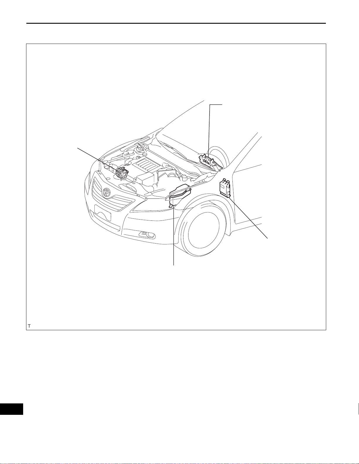
PARTS LOCATION
GENERATOR
2GR-FE CHARGING – CHARGING SYSTEM
COMBINATION METER
-CHARGE WARNING LIGHT
CH
ENGINE ROOM R/B
-ALT-S FUSE
-ALT FUSE
INSTRUMENT PANEL J/B
-GAUGE NO. 1 FUSE
-GAUGE NO. 2 FUSE
A135521E01
Page 3
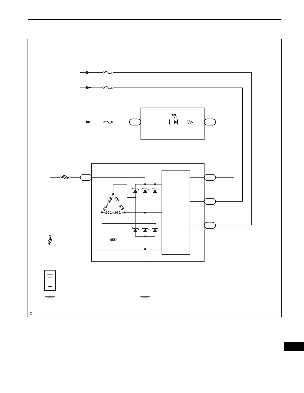
From Battery
From IG1 Relay
2GR-FE CHARGING – CHARGING SYSTEM
SYSTEM DIAGRAM
ALT-S
GAUGE No. 1
Combination Meter
CH–3
From IG2 Relay
ALT
FL MAIN
GAUGE No. 2
Generator
1
B
C19
13
F1
IG+
IG+
Charge
IC
Regulator
CHG-
IG
23
F1
4
L
C18
2
C18
1
S
C18
Battery
A138773E01
CH
Page 4

CH–4
2GR-FE CHARGING – CHARGING SYSTEM
Result
Symptom Suspected area See page
Charge Warning Light Comes ON while Driving
Noise Occurs from Generator while Engine is Running
PROBLEM SYMPTOMS TABLE
1. Clutch pulley
2. Generator assembly
1. V-ribbed belt
3. Generator assembly
CH-7
CH-82. Clutch pulley
CH
Page 5
Green
Dark
2GR-FE CHARGING – CHARGING SYSTEM
ON-VEHICLE INSPECTION
1. CHECK BATTERY ELECTROLYTE LEVEL
(a) Check the electrolyte level.
(1) If the electrolyte level is low , replace the battery
(or add distilled water) and check the charging
system.
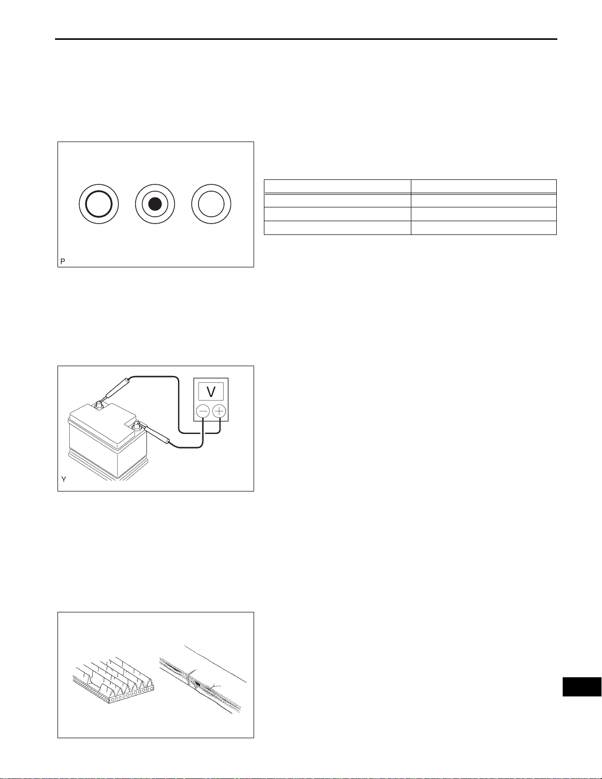
2. CHECK BATTERY SPECIFIC GRAVITY
(a) Check the color of the indicator.
Clear or Light Yellow
3. CHECK BATTERY VOLTAGE
A115815E01
Result
Indicator color Condition
Green Good
Dark Charging necessary
Clear or light yellow Replacement necessary
(a) If it has not been 20 minutes since you drove the
vehicle or since the engine was stopped, turn the
ignition switch on (IG) and turn on the electrical
systems (headlight, blower motor, rear defogger,
etc.) for 60 seconds. This will remove the surface
charge from the battery.
(b) Turn off the ignition switch and the electrical
systems.
CH–5
A081052E01
B000543
(c) Measure the battery voltage between the negative (-
) and positive (+) terminals of the battery.
Standard voltage:
12.5 to 12.9 V at 20°C (68°F)
HINT:
If the voltage is below the specification, charge the
battery.
4. CHECK BATTERY TERMINAL
(a) Check that the battery terminals are not loose or
corroded.
If the terminals are corroded, clean them.
5. CHECK FUSES
(a) Measure the resistance of the ALT fuse, ALT -S fuse,
GAUGE No. 1 fuse and GAUGE No. 2 fuse.
Standard resistance:
Below 1 Ω
If the result is not as specified, replace the fuses as
necessary.
6. CHECK V-RIBBED BELT
(a) Check the belt for wear, cracks or other signs of
damage.
If any of the following defects is found, replace the
V-ribbed belt.
• The belt is worn out, cracked, or the cords are
exposed.
• The cracks reach the cords in more than one
place.
• The belt has chunks missing from the ribs.
CH
Page 6
CH–6
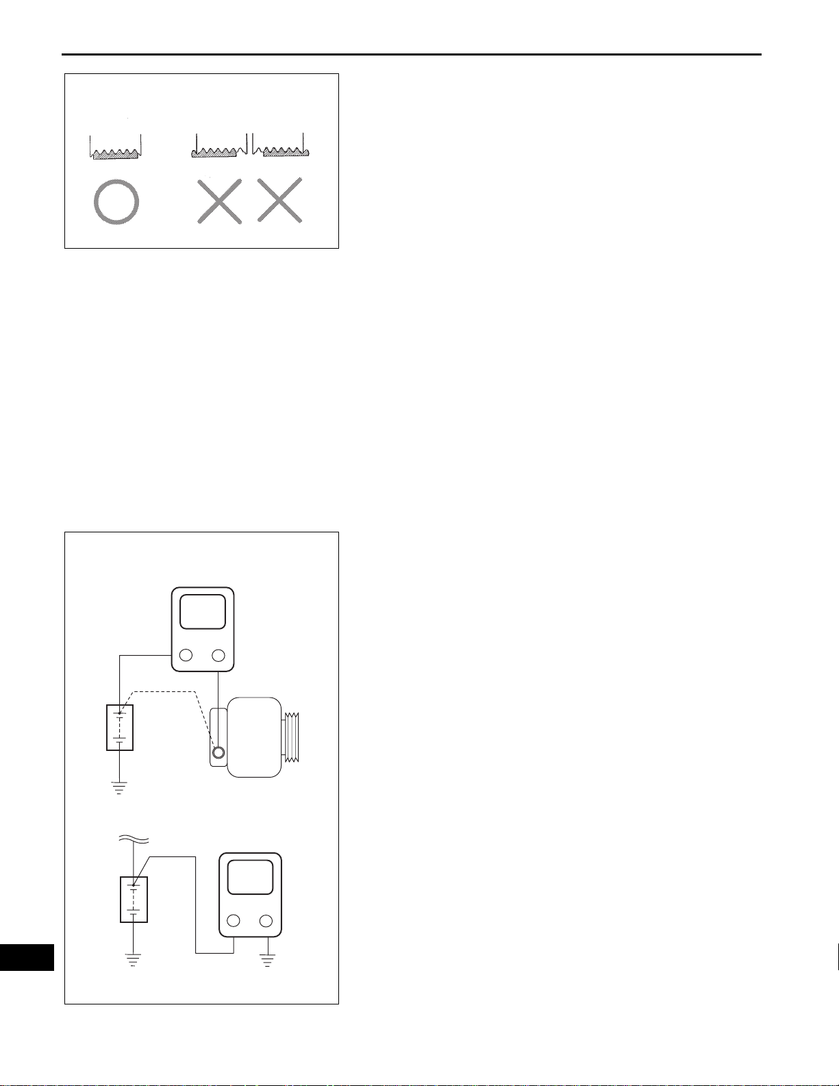
CORRECT INCORRECT
2GR-FE CHARGING – CHARGING SYSTEM
(b) Check that the belt fits properly in the ribbed
grooves.
HINT:
Check with your hand to confirm that the belt has
not slipped out of the groove on the bottom of the
pulley.
If it has slipped out, replace the V -ribbed belt. Insta ll
a new V-ribbed belt correctly.
CH
Disconnect
Wire from
Terminal B
Battery
Battery
Ammeter
A
Generator
Voltmeter
V
B000540E03
A110265E04
7. VISUALLY CHECK GENERATOR WIRING
(a) Check that the generator wiring is in good condition.
If the condition is not good, repair or replace the
generator wire.
8. LISTEN FOR ABNORMAL NOISES FROM
GENERATOR
(a) Check that there is no abnormal noise from the
generator while the engine is running.
If there is abnormal noise, replace the pulley or
generator.
9. CHECK CHARGE WARNING LIGHT CIRCUIT
(a) Turn the ignition switch on (IG). Check that the
charge warning light comes on.
(b) Start the engine and check that the light goes off.
If the light does not operate as specified,
troubleshoot the charge warning light circuit.
10. CHECK CHARGING CIRCUIT WITHOUT LOAD
(a) According to the following procedure, connect an
ammeter and voltmeter as shown in the illustration.
(1) Disconnect the wire from terminal B of the
generator and connect it to the negative (-) lead
of the ammeter.
(2) Connect the positive (+) lead of the ammeter to
terminal B of the generator.
(3) Connect the positive (+) lead of the voltmeter to
positive (+) terminal of the battery.
(4) Ground the negative (-) lead of the voltmeter.
(b) Check the charging circuit.
(1) While keeping the engine speed at 2,000 rpm,
check the readings on the ammeter and
voltmeter.
Standard amperage:
10 A or less
Standard voltage:
13.2 to 14.8 V
If the results are not as specified, replace the
generator assembly.
HINT:
• If the battery is not fully charged, the
ammeter reading may be more than the
standard amperage. In this case, increase
electrical load by operating devices such as
the wiper motor and rear window defogger.
Then, recheck the reading on the ammeter.
Page 7

2GR-FE CHARGING – CHARGING SYSTEM
11. CHECK CHARGING CIRCUIT WITH LOAD
(a) Keep the engine speed at 2,000 rpm, turn on the
high beam headlights, and turn the heater blower
switch to the "HI" position.
(b) Check the reading on the ammeter.
Standard amperage:
30 A or more
If the ammeter reading is less than the standard
amperage, replace the generator assembly.
HINT:
• If the battery is fully charged, the ammeter
reading may be less than the standard
amperage. In this case, increase electrical load
by operating devices such as the wiper motor
and rear window defogger. Then, recheck the
reading on the ammeter.
CH–7
CH
Page 8
CH–8
2GR-FE CHARGING – CHARGING SYSTEM
Charge Warning Light Comes ON while Driving
INSPECTION PROCEDURE
CHECK LOCK FUNCTION OF CLUTCH PULLEY
1
(a) Check the lock function with the pulley installed in the
vehicle.
(1) Visually check that the rotor in the generator
operates with the engine started.
(b) Check the lock function with the pulley removed from the
vehicle.
(1) Remove the generator pulley cap. Using SST, hold
the generator rotor.
(2) Turn the clutch pulley clockwise and check that the
outer ring locks.
OK:
Free Lock
SST 09820-63020
The outer ring locks.
A128078E01
OK
CHECK LOCK OF CLUTCH PULLEY
2
OK
REPLACE GENERATOR ASSEMBLY
NG
(a) Start the engine and visually check looseness of the
clutch pulley.
OK:
NG
REPLACE CLUTCH PULLEY
The clutch pulley is not loose.
TIGHTEN CLUTCH PULLEY TO THE
SPECIFIED TORQUE
CH
Page 9

2GR-FE CHARGING – CHARGING SYSTEM
Noise Occurs from Generator while Engine is Running
INSPECTION PROCEDURE
CHECK LOOSENESS OF V-RIBBED BELT
1
(a) Check the tension of the belt by pushing it down with a
finger.
OK:
The tension of the belt is enough.
CH–9
OK
CHECK V-RIBBED BELT FOR WEAR
2
OK
CHECK CLUTCH PULLEY FOR WEAR
3
NG
(a) Check the V-ribbed belt for wear.
OK:
NG
(a) Check the clutch pulley groove for wear or other defects.
OK:
NG
REPLACE V-RIBBED BELT TENSIONER
ASSEMBLY
The V-ribbed belt is not worn.
REPLACE V-RIBBED BELT
The clutch pulley groove is not damaged.
REPLACE CLUTCH PULLEY
OK
CHECK FOR NOISE WHILE CLUTCH PULLEY IS OPERATING
4
OK
REPLACE GENERATOR ASSEMBLY
(a) Perform a driving test and check if noise occurs when
decelerating.
OK:
Noise does not occur.
NG
REPLACE CLUTCH PULLEY
CH
Page 10

ENGINE2GR-FE CHARGING
GENERATOR
COMPONENTS
V-BANK COVER SUB-ASSEMBLY
2GR-FE CHARGING – GENERATOR
5.0 (51, 44 in.*lbf)
x2
AIR CLEANER INLET ASSEMBLY
CH–9
5.0 (51, 44 in.*lbf)
COOL AIR INTAKE DUCT SEAL
NO. 1 AIR CLEANER INLET
AIR CLEANER CAP SUB-ASSEMBLY
AIR CLEANER FILTER ELEMENT
N*m (kgf*cm, ft.*lbf)
: Specified torque
CH
A134975E01
Page 11

CH–10
2GR-FE CHARGING – GENERATOR
HOOD LOCK ASSEMBLY
7.5 (77, 66 in.*lbf)
RADIATOR GRILLE
PROTECTOR
7.0 (71, 62 in.*lbf)
x2
7.0 (71, 62 in.*lbf)
7.5 (77, 66 in.*lbf)
x4
RADIATOR SUPPORT UPPER
HORN CONNECTOR
CH
x2
FRONT BUMPER ASSEMBLY
N*m (kgf*cm, ft.*lbf)
: Specified torque
x2
x2
x9
FRONT WHEEL OPENING
EXTENSION PAD RH
FRONT BUMPER
ENERGY ABSORBER
ENGINE UNDER COVER LH
ENGINE UNDER COVER RH
FRONT WHEEL OPENING
EXTENSION PAD LH
A133359E05
Page 12

2GR-FE CHARGING – GENERATOR
FRONT FENDER APRON SEAL RH
CH–11
V-RIBBED BELT
9.8 (100, 87 in.*lbf)
8.4 (86, 74 in.*lbf)
43 (438, 32)
GENERATOR ASSEMBLY
RADIATOR ASSEMBLY
WIRE HARNESS
CLAMP STAY
43 (438, 32)
RADIATOR INLET HOSE
RADIATOR OUTLET HOSE
20 (204, 15)
20 (204, 15)
GENERATOR BRACKET
FAN MOTOR
CONNECTOR
FAN SHROUD
5.0 (51, 44 in.*lbf)
N*m (kgf*cm, ft.*lbf)
x4
CH
: Specified torque
A133878E01
Page 13

CH–12
2GR-FE CHARGING – GENERATOR
GENERATOR DRIVE END FRAME
BEARING RETAINER
GENERATOR
PULLEY CAP
111 (1,125, 81)
GENERATOR
CLUTCH PULLEY
x4
2.3 (23, 20 in.*lbf)
GENERATOR
ROTOR ASSEMBLY
GENERATOR DRIVE END
FRAME BEARING
GENERATOR REAR END COVER
GENERATOR TERMINAL INSULATOR
GENERATOR
WASHER
x3
x2
CH
N*m (kgf*cm, ft.*lbf)
Non-reusable part
4.6 (47, 41 in.*lbf)
1.8 (18, 16 in.*lbf)
x4
GENERATOR BRUSH
HOLDER ASSEMBLY
5.8 (59, 51 in.*lbf)
GENERATOR COIL ASSEMBLY
: Specified torque
A135482E01
Page 14

2GR-FE CHARGING – GENERATOR
REMOVAL
1. DISCONNECT CABLE FROM NEGATIVE BATTERY
TERMINAL
2. REMOVE FRONT WHEEL RH
3. REMOVE FRONT FENDER APRON SEAL RH
4. REMOVE FRONT WHEEL OPENING EXTENSION
PAD RH
5. REMOVE FRONT WHEEL OPENING EXTENSION
PAD LH
6. REMOVE ENGINE UNDER COVER RH
7. REMOVE ENGINE UNDER COVER LH
8. DRAIN ENGINE COOLANT (See page CO-5)
9. REMOVE V-BANK COVER SUB-ASSEMBLY (See
page EM-23)
10. REMOVE COOL AIR INTAKE DUCT SEAL (See page
EM-23)
CH–13
11. REMOVE AIR CLEANER INLET ASSEMBLY (See
page EM-24)
12. REMOVE AIR CLEANER CAP SUB-ASSEMBLY (See
page ES-503)
13. REMOVE NO. 1 AIR CLEANER INLET (See page EM-
24)
14. REMOVE FRONT BUMPER ASSEMBLY (w/o Fog
Light) (See page ET-5)
15. REMOVE FRONT BUMPER ASSEMBLY (w/ Fog
Light) (See page ET-6)
16. REMOVE FRONT BUMPER ENERGY ABSORBER
(See page ET-9)
17. SEPARATE RADIATOR RESERVE TANK HOSE (See
page CO-24)
18. SEPARATE RADIATOR INLET HOSE (See page CO-
24)
19. SEPARATE RADIATOR OUTLET HOSE (See page
CO-24)
20. SEPARATE NO. 1 OIL COOLER INLET HOSE (See
page CO-25)
21. SEPARATE NO. 1 OIL COOLER OUTLET HOSE (See
page CO-25)
22. REMOVE RADIATOR SUPPORT UPPER (See page
CO-25)
23. REMOVE FAN SHROUD (See page CO-26)
24. REMOVE RADIATOR ASSEMBLY (See page CO-26)
25. REMOVE V-RIBBED BELT (See page EM-6)
CH
Page 15

CH–14
2GR-FE CHARGING – GENERATOR
26. REMOVE GENERATOR ASSEMBLY
(a) Remove the terminal cap.
(b) Remove the nut and disconnect the wire harness
from terminal B.
(c) Disconnect the generator connector from the
generator assembly.
(d) Disconnect the connector from the compressor and
magnetic clutch.
(e) Disconnect the 2 wire harness clamps.
A133865
(f) Remove the 2 bolts.
A133866
A133867
A128066
(g) Remove the bolt from the cylinder block.
(h) Disconnect the wire harness clamp and remove the
generator assembly.
(i) Remove the bolt and wire harness clamp stay.
(j) Remove the bolt and bracket.
CH
A135391
Page 16

SST (A)
SST (B)
2GR-FE CHARGING – GENERATOR
DISASSEMBLY
1. REMOVE GENERATOR CLUTCH PULLEY
(a) Using a screwdriver, remove the generator pulley
cap.
A128068E01
(b) Set SST (A) and (B).
SST 09820-63020
(c) Clamp SST (A) in a vise.
A128069E01
CH–15
SST (A)
Rotor Shaft
Clutch Pulley
SST (B)
(d) Place the rotor shaft end into SST (A).
SST (B)
A135194E01
(e) Fit SST (B) to the clutch pulley.
SST (B)
A135195E01
(f) Loosen the pulley by turning SST ( B) in the direction
shown in the illustration.
(g) Remove the generator assembly from the SST.
(h) Remove the clutch pulley from the rotor shaft.
SST (B)
A135196E01
CH
Page 17

CH–16
2GR-FE CHARGING – GENERATOR
2. REMOVE GENERATOR REAR END COVER
(a) Place the generator assembly on the clutch pulley.
A135197
(b) Remove the 3 nuts and generator rear end cover.
A128071
A128072
A128073
3. REMOVE GENERATOR TERMINAL INSULATOR
(a) Remove the terminal insulator from the generator
coil.
4. REMOVE GENERATOR BRUSH HOLDER ASSEMBLY
(a) Remove the 2 screws and brush holder from the
generator coil.
5. REMOVE GENERATOR COIL ASSEMBLY
(a) Remove the 4 bolts.
CH
A128074
Page 18

Hold
SST
2GR-FE CHARGING – GENERATOR
(b) Using SST, remove the generator coil assembly.
Turn
SST 09950-40011 (09951-04020, 09952-04010,
09953-04020, 09954-04010, 09955-04071,
SST
A118275E01
09957-04010, 09958-04011)
6. REMOVE GENERATOR ROTOR ASSEMBLY
(a) Remove the generator washer.
A118365E01
CH–17
SST
(b) Remove the generator rotor assembly.
A118367E01
7. REMOVE GENERATOR DRIVE END FRAME
BEARING
(a) Remove the 4 screws and retainer plate from the
drive end frame.
A128076
(b) Using SST and a hammer, tap out the drive end
frame bearing from the drive end frame.
SST 09950-60010 (09951-00250), 09950-70010
(09951-07100)
A128077E01
CH
Page 19

CH–18
Free Lock
Length
2GR-FE CHARGING – GENERATOR
INSPECTION
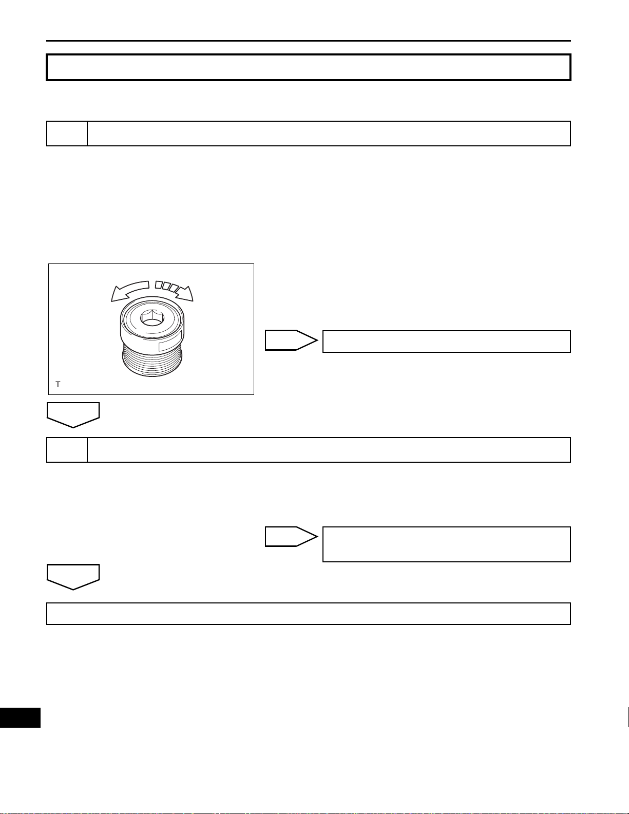
1. INSPECT GENERATOR CLUTCH PULLEY
(a) Hold the center of the pulley, and confirm that the
outer ring turns counterclockwise and does not turn
clockwise.
If the result is not as specified, replace the clutch
pulley.
A128078E01
2. INSPECT GENERATOR BRUSH HOLDER ASSEMBLY
(a) Using vernier calipers, measure the length of the
exposed brushes.
Standard exposed length:
9.5 to 11.5 mm (0.374 to 0.453 in.)
Minimum exposed length:
4.5 mm (0.177 in.)
If the exposed length is less than the minimum,
replace the brush holder assembly.
A128079E01
CH
Slip Rings
Slip Ring
Rotor
Ohmmeter
Ohmmeter
3. INSPECT GENERATOR ROTOR ASSEMBLY
(a) Check that the generator rotor bearing is not rough
or worn.
If necessary, replace the generator rotor assembly.
A079306E02
(b) Check the generator rotor for an open circuit.
(1) Using an ohmmeter, measure the resistance
between the slip rings.
Standard resistance
Condition Specified condition
Approx. 20°C (68°F) 2.3 to 2.7 Ω
If the result is not as specified, replace the
generator rotor assembly.
B012264E08
(c) Check the rotor for a short to ground.
(1) Using an ohmmeter, measure the resistance
between the slip ring and rotor.
Standard resistance
Tester condition Specified condition
Slip ring - Rotor 1 MΩ or higher
If the result is not as specified, replace the
generator rotor assembly.
B012265E01
Page 20

Diameter
2GR-FE CHARGING – GENERATOR
(d) Using vernier calipers, measure the slip ring
diameter.
Standard diameter:
14.2 to 14.4 mm (0.559 to 0.567 in.)
Minimum diameter:
14.0 mm (0.551 in.)
If the diameter is less than the minimum, replace the
generator rotor assembly.
A124106E01
4. INSPECT GENERATOR DRIVE END FRAME
BEARING
(a) Check that the drive end frame bearing is not rough
or worn.
If necessary, replace the drive end frame bearing.
A128080
CH–19
SST
Ta b
Cutout
REASSEMBLY
1. INSTALL GENERATOR DRIVE END FRAME
BEARING
(a) Using SST and a press, press in a new generator
drive end frame bearing.
SST 09950-60010 (09951-00470), 09950-70010
(09951-07100)
A128081E01
(b) Fit the tabs on the retainer plate into the cutouts on
the drive end frame to install the retainer plate.
(c) Install the 4 screws.
Torque: 2.3 N*m (23 kgf*cm, 20 in.*lbf)
2. INSTALL GENERATOR ROTOR ASSEMBLY
(a) Place the drive end frame on the clutch pulley.
A137712E01
(b) Install the generator rotor assembly to the drive end
frame.
A118367E01
CH
Page 21

CH–20
2GR-FE CHARGING – GENERATOR
(c) Place a new generator washer on the generator
rotor.
A118365E01
Deep socket
wrench (21 mm)
Pin
3. INSTALL GENERATOR COIL ASSEMBLY
(a) Using a deep socket wrench (21 mm) and a press,
slowly press in the generator coil assembly.
A128082E01
(b) Install the 4 bolts.
Torque: 5.8 N*m (59 kgf*cm, 51 in.*lbf)
A128074
4. INSTALL GENERATOR BRUSH HOLDER ASSEMBLY
(a) While pushing the 2 brushes into the generator
brush holder assembly, insert a φ1.0 mm (0.039 in.)
pin into the brush holder hole.
CH
A079315E04
(b) Install the brush holder assembly to the generator
coil with the 2 screws.
Torque: 1.8 N*m (18 kgf*cm, 16 in.*lbf)
(c) Pull out the pin from the generator brush holder.
Pin
A079316E02
Page 22

2GR-FE CHARGING – GENERATOR
5. INSTALL GENERATOR TERMINAL INSULATOR
(a) Install the terminal insulator to the generator coil.
NOTICE:
Pay attention to installation direction of the
terminal insulator.
A128083E01
6. INSTALL GENERATOR REAR END COVER
(a) Install the generator rear end cover to the generator
coil with the 3 nuts.
Torque: 4.6 N*m (47 kgf*cm, 41 in.*lbf)
7. REMOVE GENERATOR CLUTCH PULLEY
(a) Temporarily install the clutch pulley onto the rotor
shaft.
A128071
CH–21
SST (A)
SST (B)
SST (A)
Clutch Pulley
Rotor Shaft
(b) Set SST (A) and (B).
SST 09820-63020
A128084E01
(c) Clamp SST (A) in a vise.
(d) Place the rotor shaft end into SST (A).
SST (B)
A135194E01
(e) Fit SST (B) to the clutch pulley.
SST (B)
SST (B)
CH
A135195E01
Page 23

CH–22
SST (B)
2GR-FE CHARGING – GENERATOR
(f) T ighten the pulley by turnin g SST (B) in the direction
shown in the illustration.
Torque: 111 N*m (1,125 kgf*cm, 81 ft.*lbf)
NOTICE:
The torque shown above should be used for
tightening without using the SST. When the SST
is used for tightening, the torque should be
calculated based on the length of the SST (See
page IN-6).
(g) Remove the generator assembly from the SST.
(h) Check that the clutch pulley rotates smoothly.
(i) Install a new clutch pulley cap to the clutch pulley.
100 mm (3.937 in.)
A135208E01
INSTALLATION
1. INSTALL GENERATOR ASSEMBLY
(a) Install the bracket with the bolt.
Torque: 20 N*m (204 kgf*cm, 15 ft.*lbf)
A135391
A128066
A133867
(b) Install the wire harness clamp stay.
Torque: 8.4 N*m (86 kgf*cm, 74 in.*lbf)
(c) Connect the wire harness clamp.
(d) Install the generator assembly to the cylinder block
with the bolt.
Torque: 20 N*m (204 kgf*cm, 15 ft.*lbf)
CH
Page 24

2GR-FE CHARGING – GENERATOR
(e) Install the 2 bolts.
Torque: 43 N*m (438 kgf*cm, 32 ft.*lbf)
A133866
(f) Connect the generator connector to the generator
assembly.
(g) Install the generator wire with the nut.
Torque: 9.8 N*m (100 kgf*cm, 87 in.*lbf)
(h) Install the terminal cap.
(i) Connect the 2 wire harness clamps.
(j) Connect the magnetic clutch connector to the
compressor and magnetic clutch.
CH–23
A133865
2. INSTALL V-RIBBED BELT (See page EM-7)
3. INSTALL RADIATOR ASSEMBLY (See page CO-31)
4. INSTALL FAN SHROUD (See page CO-32)
5. INSTALL RADIATOR SUPPORT UPPER (See page
CO-32)
6. CONNECT NO. 1 OIL COOLER OUTLET TUBE (See
page CO-33)
7. CONNECT NO. 1 OIL COOLER INLET TUBE (See
page CO-33)
8. CONNECT RADIATOR OUTLET HOSE (See page CO-
33)
9. CONNECT RADIATOR INLET HOSE (See page CO-
33)
10. CONNECT RADIATOR RESERVE TANK HOSE (See
page CO-34)
11. INSTALL FRONT BUMPER ENERGY ABSORBER
(See page ET-10)
12. INSTALL FRONT BUMPER ASSEMBLY (w/o Fog
Light) (See page ET-13)
13. INST ALL FRONT BUMPER ASSEMBLY (w/ Fog Light)
(See page ET-14)
14. INSTALL NO. 1 AIR CLEANER INLET (See page EM-
49)
15. INSTALL AIR CLEANER CAP SUB-ASSEMBLY (See
page ES-506)
16. INST ALL AIR CLEANER INLET ASSEMBLY (See page
EM-50)
CH
Page 25

CH–24
2GR-FE CHARGING – GENERATOR
17. CONNECT CABLE TO NEGATIVE BATTERY
TERMINAL (See page EM-51)
18. ADD ENGINE COOLANT (See page CO-6)
19. CHECK FOR ENGINE COOLANT LEAKS (See page
CO-1)
20. INSTALL V-BANK COVER SUB-ASSEMBLY (See
page EM-52)
21. INSTALL COOL AIR INTAKE DUCT SEAL (See page
EM-52)
22. INSTALL FRONT FENDER APRON SEAL RH
23. INSTALL ENGINE UNDER COVER RH
24. INSTALL ENGINE UNDER COVER LH
25. INST ALL FRONT WHEEL OPENING EXTENSION P AD
RH
26. REMOVE FRONT WHEEL OPENING EXTENSION
PAD LH
27. INSTALL FRONT WHEEL RH (See page EM-7)
CH
 Loading...