

Page 1
2AZ-FE EMISSION CONTROL – EMISSION CONTROL SYSTEM
ENGINE2AZ-FE EMISSION CONTROL
EMISSION CONTROL SYSTEM
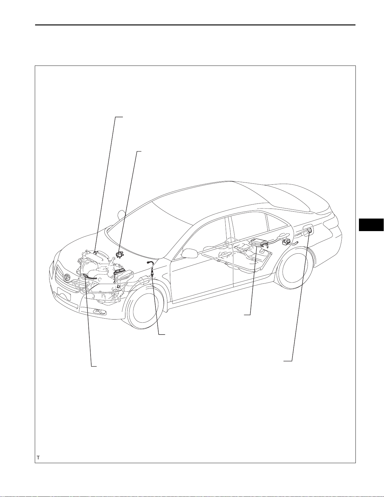
PARTS LOCATION
VENTILATION VALVE
VACUUM SWITCHING VALVE
EC–1
HEATED OXYGEN SENSOR
AIR FUEL RATIO SENSOR
EC
CANISTER
FUEL TANK CAP
A135646E03
Page 2
EC–2
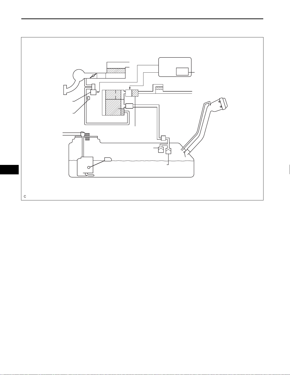
For PZEV :
2AZ-FE EMISSION CONTROL – EMISSION CONTROL SYSTEM
SYSTEM DIAGRAM
Air Cleaner
ECM
EC
Intake Manifold
EVAP VSV
Service Port
Canister
Soak Timer
Air Filter
Fuel Cap
Pump Module
Roll-over Valve
Cut-off Valve
Fuel Tank
A128935E01
Page 3
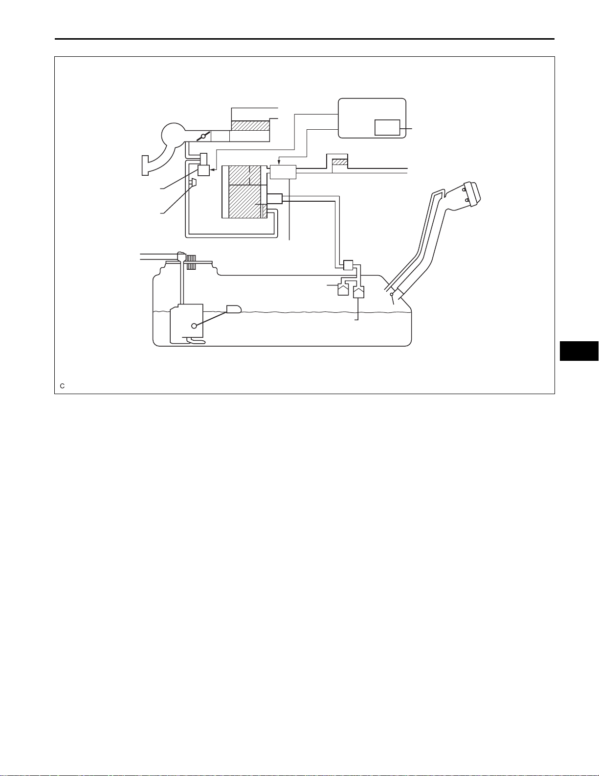
Except PZEV :
2AZ-FE EMISSION CONTROL – EMISSION CONTROL SYSTEM
Air Cleaner
ECM
EC–3
Intake Manifold
EVAP VSV
Service Port
Canister
Pump Module
Roll-over Valve
Cut-off Valve
Fuel Tank
Soak Timer
Air Filter
Fuel Cap
EC
A128936E01
Page 4
EC–4
2AZ-FE EMISSION CONTROL – EMISSION CONTROL SYSTEM
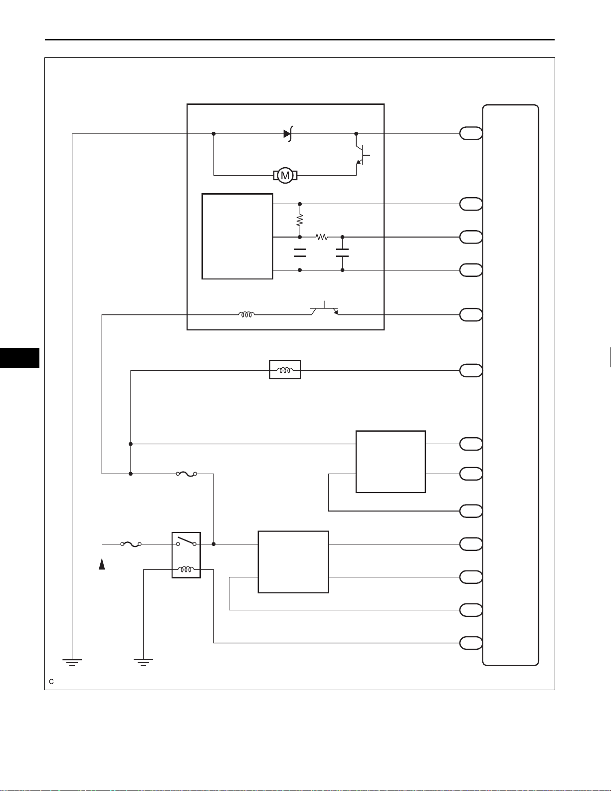
N17
Canister Pump Module
ECM
EC
MGND MTRB
6
Leak Detection Pump
Canister
Pressure
Sensor
Vent Valve
VLVB
9
C6 VSV (Purge)
12
1
VCC
4
VOUT
3
SGND
2
VGND
8
C22
Heated Oxgen Sensor
34
A24
70
C24
71
C24
94
C24
42
A24
49
C24
VCPP
PPMP
EPPM
VPMP
PRG
EFI-MAIN
From Battery
EFI No. 3
EFI
C15
Air Fuel Ratio Sensor
2
1
+B
HA1A
A1A-
A1A+
87
C24
64
C24
47
C24
113
C24
112
C24
109
C24
44
A24
EX1B
OX1B
HT1B
A1A-
A1A+
HA1A
MREL
A135723E01
+B
2
HT1B
1
4
3
E2
OX1B
4
3
Page 5
2AZ-FE EMISSION CONTROL – EMISSION CONTROL SYSTEM
ON-VEHICLE INSPECTION
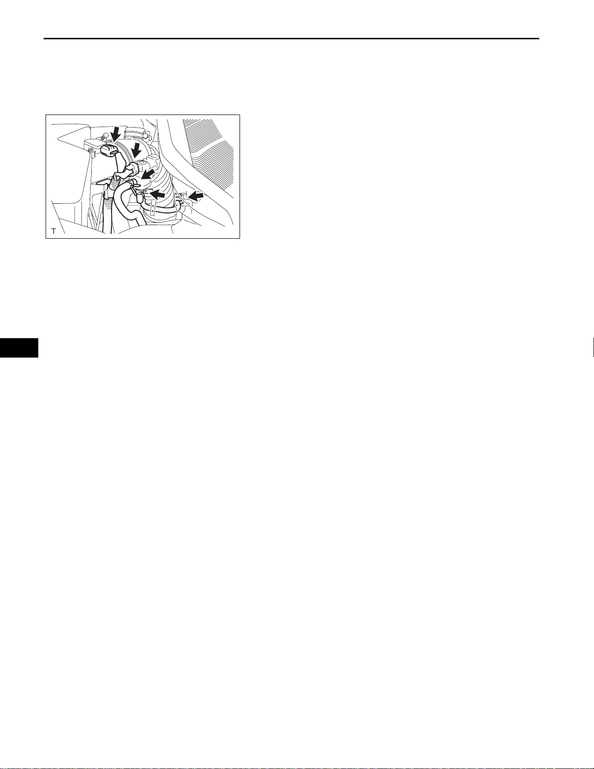
1. VISUALLY INSPECT HOSE, CONNECTIONS AND
GASKETS
(a) Check that there are no cracks, leaks or damage.
HINT:
• Detachment or other problems with the engine oil
dipstick, filler cap, PCV hose and other
components may cause the engine to run
B000412
2. INSPECT FUEL CUT RPM
(a) Start and warm up the engine.
(b) Open the throttle valve and keep the engine speed
(c) Use a sound scope to check for injector operating
(d) Check that when the accelerator pedal is released,
improperly.
• Disconnection, looseness or cracks in the parts
of the air induction system between the throttle
body and cylinder head will allow air suction and
cause an engine failure or engine malfunctions.
If the result is not as specified, replace the parts as
necessary.
at 3,000 rpm.
sounds.
injector operating sounds stop momentarily (at
2,500 rpm) and then resume (at 1400 rpm).
Standard
Item Specified condition
Fuel cut off rpm 2,500 rpm
Fuel return rpm 1,400 rpm
EC–5
EC
A128092
If the result is not specified, check the injectors,
wiring and ECM.
3. INSPECT LINE AND CONNECTORS
(a) Visually check for loose connections, sharp bends
or damage.
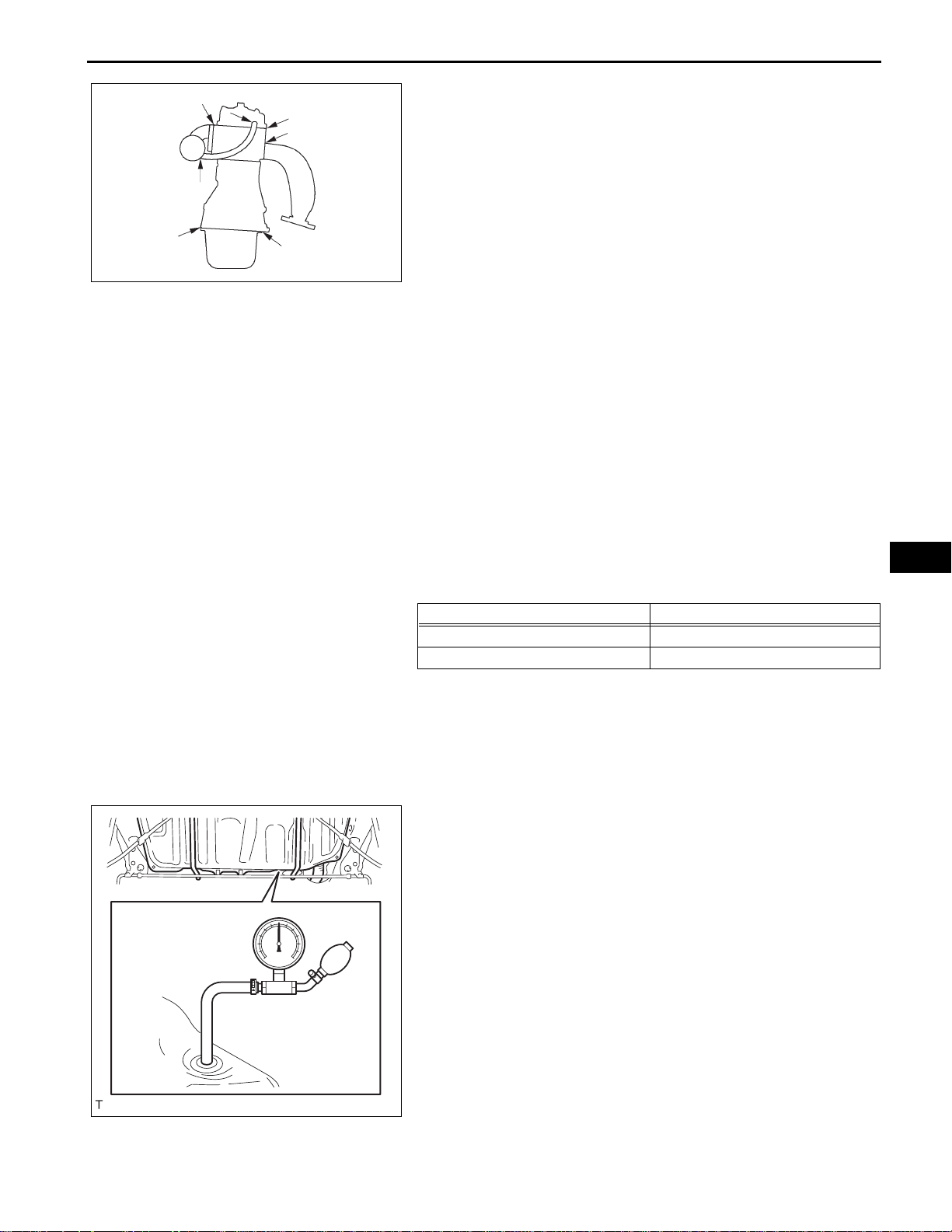
4. CHECK AIR TIGHTNESS IN FUEL T ANK AND FILLER
PIPE
(a) Disconnect the vent line hose from the fuel tank.
(b) Connect the pressure gauge to the fuel tank.
(c) Apply pressure to the fuel tank to create an internal
pressure of 4 kPa (41 gf/cm
2
, 0.58 psi).
(d) Check that the internal pressure of the fuel tank is
maintained for 1 minute.
(e) Check the connected portions of each hose and
pipe.
(f) Check the installed parts on the fuel tank.
If any malfunctions, damage or other problems are
found, replace the fuel tank and filler pipe.
(g) Reconnect the vent line hose to the fuel tank.
Page 6
EC–6
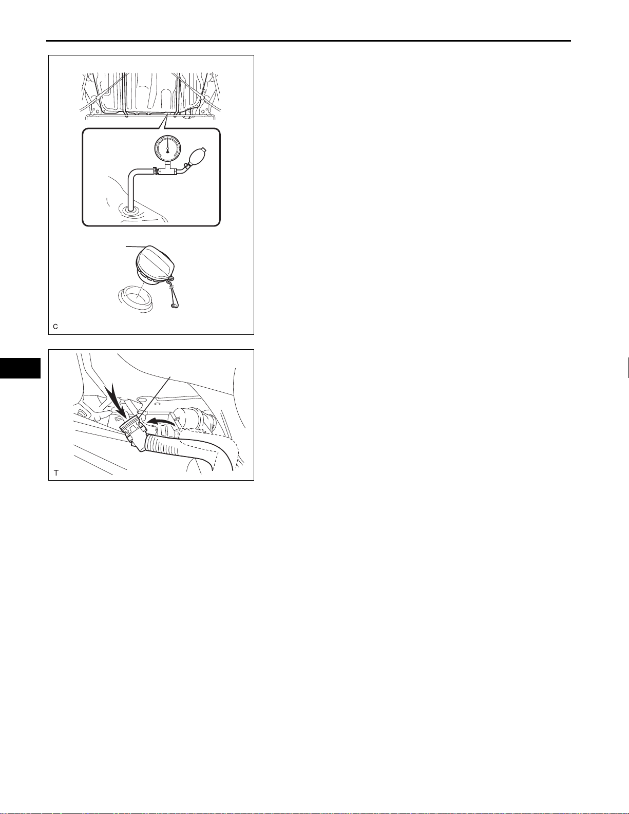
Fuel Tank Cap
2AZ-FE EMISSION CONTROL – EMISSION CONTROL SYSTEM
5. REMOVE FUEL TANK ASSEMBLY
(a) Disconnect the vent line hose from the fuel tank.
(b) Connect the pressure gauge to the fuel tank.
(c) Fill the fuel tank with fuel.
(d) Apply pressure of 4 kPa (41 gf/cm
vent port of the fuel tank.
HINT:
Check the amount of fuel in the fuel tank. When the
fuel tank is full, the float valve of the fill check valve
is closed and no air can pass through.
(e) Remove the fuel tank cap, and check that the
pressure drops.
If the pressure does not drop, replace the fuel tank
assembly.
(f) Reconnect the vent line hose to the fuel tank.
A126204E01
2
, 0.58 psi) to the
EC
Air
Air Inlet Hose
6. REMOVE AIR INLET LINE
(a) Disconnect the air inlet line hose from the charcoal
canister.
(b) Check that air can flow freely into the air inlet line.
If air cannot flow freely into the air inlet line, repair or
replace it.
(c) Reconnect the air inlet line hose to the charcoal
canister.
A128093E02
Page 7
ENGINE2AZ-FE EMISSION CONTROL
CANISTER
COMPONENTS
for PZEV:
2AZ-FE EMISSION CONTROL – CANISTER
EC–7
39 (398, 29)
EC
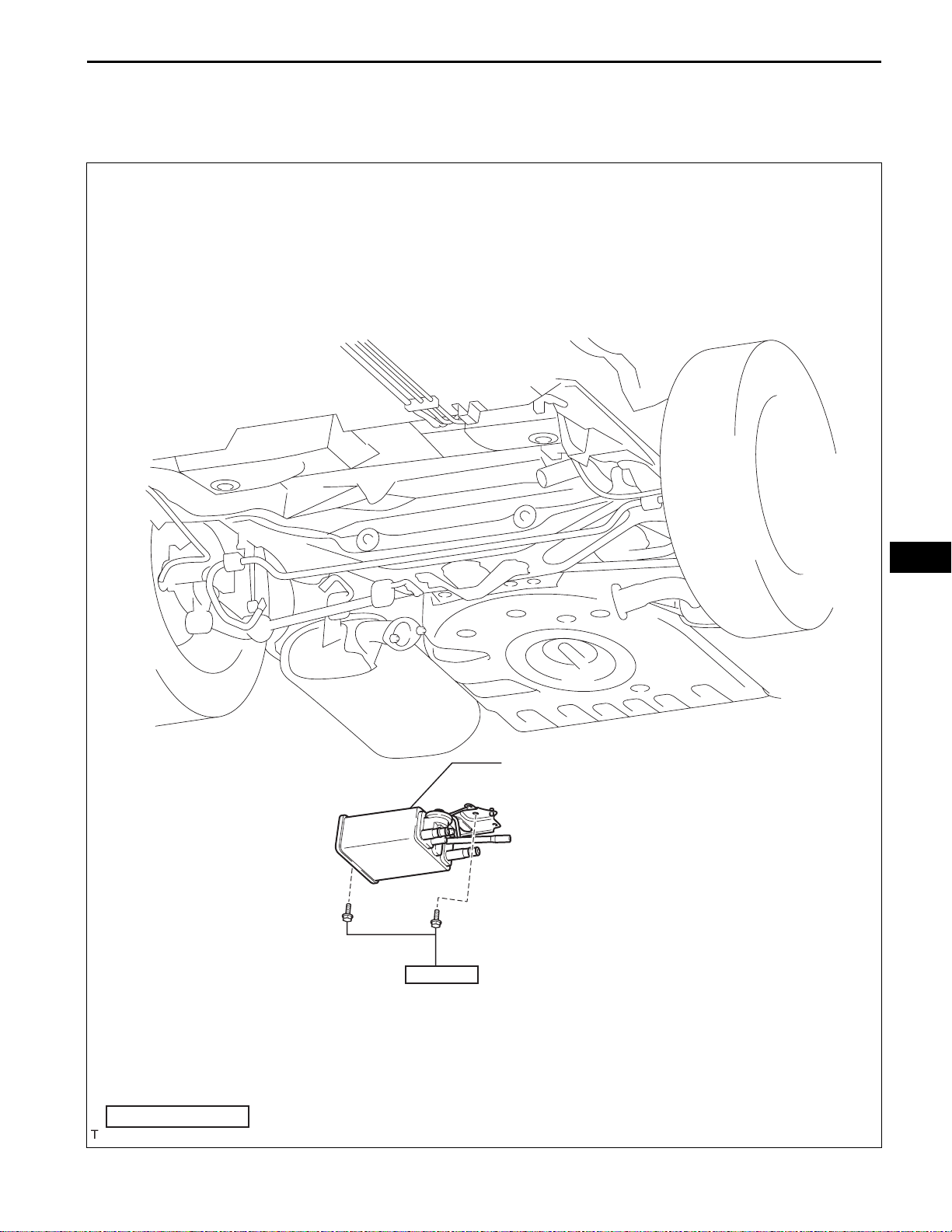
CHARCOAL CANISTER ASSEMBLY
N*m (kgf*cm, ft.*lbf)
: Specified torque
A135649E03
Page 8
EC–8
except PZEV:
2AZ-FE EMISSION CONTROL – CANISTER
EC
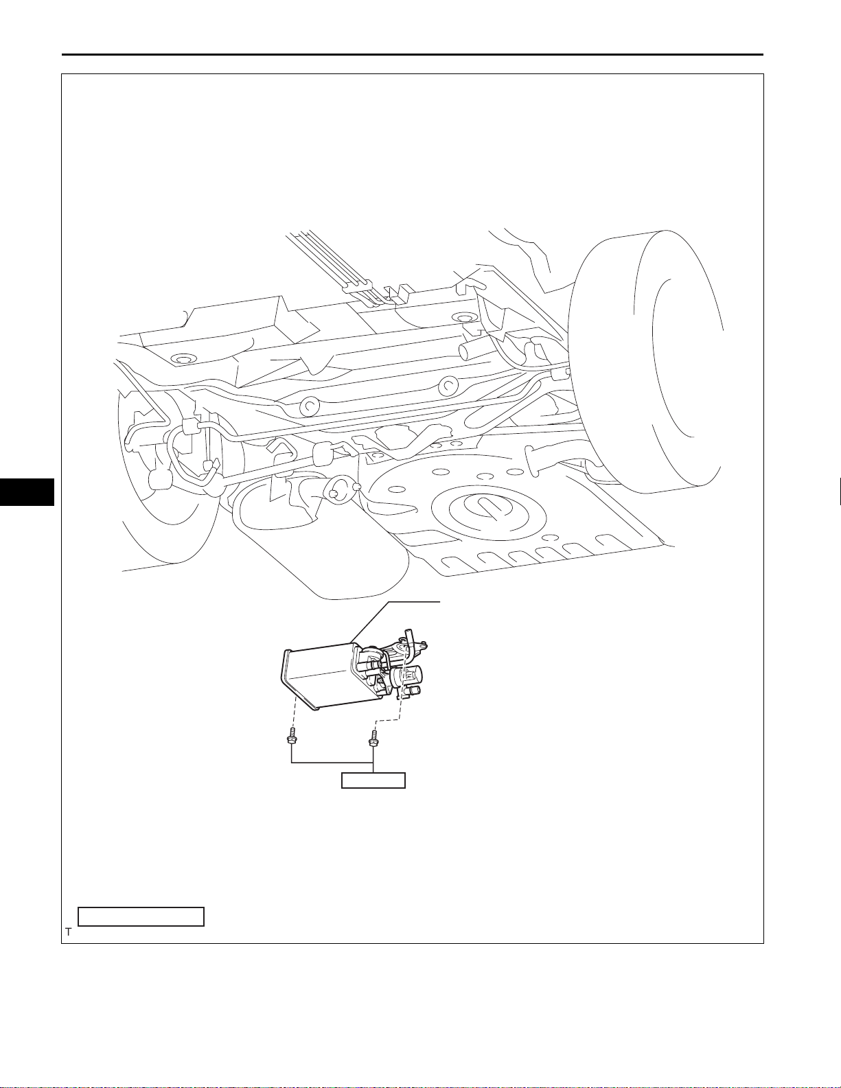
CHARCOAL CANISTER ASSEMBLY
39 (398, 29)
N*m (kgf*cm, ft.*lbf)
: Specified torque
A135648E06
Page 9

Pinch A
2AZ-FE EMISSION CONTROL – CANISTER
REMOVAL
1. REMOVE FUEL TANK ASSEMBLY
HINT:
(See page FU-34)
2. REMOVE CHARCOAL CANISTER ASSEMBLY
(a) Disconnect the fuel tank vent hose from the
charcoal canister.
A
(1) Push the connector deep inside.
(2) Pinch portion A.
(3) Pull out the connector.
EC–9
Pinch A
Pinch
Pinch
Push
Push
A
A132954E01
(b) Disconnect the charcoal canister filter sub-assembly
from the charcoal canister.
(1) Push the connector deep inside.
A
(2) Pinch portion A.
(3) Pull out the connector.
(c) Disconnect the vapor pressure sensor connector.
A
(d) Disconnect the wire harness clamp.
(e) Disconnect the purge line hose from the charcoal
canister.
A128095E01
EC
(f) Remove the 2 bolts, clip and charcoal canister.
A128096
A112883E01
INSPECTION
1. INSPECT CHARCOAL CANISTER ASSEMBLY
(a) Visually check the charcoal canister for cracks or
damage.
If cracks or damage are found, replace the charcoal
canister assembly.
Page 10

EC–10
Vent Port
Purge Port
Air
2AZ-FE EMISSION CONTROL – CANISTER
(b) Check charcoal canister operation.
(1) With the purge port closed, blow 1.10 kPa (1 1.2
2
gf/cm
, 0.16 psi) of air into the vent port, and
check that air flows from the air inlet port.
If the result is not as specified, replace the
charcoal canister assembly.
Air Inlet Port
A111044E02
EC
Purge Port
Vent Port
Purge Port
Air Inlet Port
Air Inlet Port
Pressure Gauge
Air
A111043E02
(2) With the vent port closed, blow 1.10 kPa (11.2
2
gf/cm
, 0.16 psi) of air into the air inlet port, and
check that air flows from the purge port.
If the result is not as specified, replace the
charcoal canister assembly.
(c) Check for air leakage.
(1) With the purge port and air inlet port closed,
apply 19.6 kPa (0.2 kgf/cm
2
, 2.81 psi) of
pressurized air into the vent port, then confirm
that pressure is retained for 1 minute.
If the result is not as specified, replace the
charcoal canister assembly.
Vent Port
Air
SST
A
A111042E02
(d) Check the leak detection pump.
(1) Remove the detection pump from the charcoal
canister.
(2) Check that air flows from port A to B.
If the result is not as specified, replace the
charcoal canister assembly.
B
A112886E01
Page 11

2AZ-FE EMISSION CONTROL – CANISTER
EC–11
(3) Connect the positive (+) lead of the battery to
Valve
Closed
terminal 7 and the negative (-) lead to terminal
6.
6
7
(4) Check that the valve is closed.
If the result is not as specified, replace the
charcoal canister assembly.
(5) Install the detection pump.
A111047E01
INSTALLATION
1. INSTALL CHARCOAL CANISTER ASSEMBLY
(a) Install the 2 bolts, clip and charcoal canister.
Torque: 39 N*m (398 kgf*cm, 29 ft.*lbf)
(b) Connect the purge line hose to the charcoal
canister.
(c) Connect the wire harness clamp.
(d) Connect the vapor pressure sensor connector.
(e) Connect the charcoal canister filter sub-assembly to
the charcoal canister.
(f) Connect the fuel tank vent hose to the charcoal
canister.
A128096
2. INSTALL FUEL TANK ASSEMBLY
HINT:
(See page FU-39)
3. CHECK FOR EXHAUST GAS LEAKS
EC
Page 12

EC–12
ENGINE2AZ-FE EMISSION CONTROL
2AZ-FE EMISSION CONTROL – VACUUM SWITCHING VALVE
VACUUM SWITCHING VALVE
COMPONENTS
VACUUM SWITCHING VALVE CONNECTOR
VACUUM SWITCHING VALVE
PURGE LINE HOSE
PURGE LINE HOSE
EC
A135652E03
Page 13

2AZ-FE EMISSION CONTROL – VACUUM SWITCHING VALVE
23 to 26 Ω
1
A135666
REMOVAL
1. REMOVE VACUUM SWITCHING VALVE
(a) Disconnect the vacuum switching valve connector.
(b) Disconnect the wire harness clamp.
(c) Disconnect the 2 purge line hoses from the purge
VSV.
(d) Remove the vacuum switching valve.
INSPECTION
1. INSPECT VACUUM SWITCHING VALVE
(a) Measure the resistance of the purge VSV.
Standard resistance
Tester Connection Specified Condition
1 - 2 23 to 26 Ω at 20°C (68°F)
1 - Body ground
2 - Body ground
10 MΩ or higher
EC–13
2
10 MΩ or higher
F
E
If the result is not as specified, replace the purge
VSV.
EC
A124791E01
(b) Check the operation of the purge VSV.
(1) Check that air does not flow from port E to port
F.
Air
A124792E01
(2) Apply battery voltage across the terminals.
(3) Check that air flows from port E to port F.
If the result is not as specified, replace the
purge VSV.
F
E
Air
A124793E01
Page 14
EC–14
2AZ-FE EMISSION CONTROL – VACUUM SWITCHING VALVE
INSTALLATION
1. REMOVE VACUUM SWITCHING VALVE
(a) Install the vacuum switching valve onto the air
cleaner hose.
(b) Connect the 2 purge line hoses to the vacuum
switching valve.
(c) Connect the vacuum switching valve connector.
A135666
EC
Page 15

2AZ-FE EMISSION CONTROL – VENTILATION VALVE
ENGINE2AZ-FE EMISSION CONTROL
VENTILATION VALVE
COMPONENTS
NO. 1 ENGINE COVER SUB-ASSEMBLY
VENTILATION VALVE SUB-ASSEMBLY
EC–15
7.0 (71, 62 in.*lbf)
VENTILATION HOSE
EC
N*m (kgf*cm, ft.*lbf)
: Specified torque
Precoated part
A135650E03
Page 16

EC–16
2AZ-FE EMISSION CONTROL – VENTILATION VAL VE
REMOVAL
1. REMOVE NO. 1 ENGINE COVER SUB-ASSEMBLY
2. REMOVE VENTILATION VALVE SUB-ASSEMBLY
(a) Disconnect the ventilation hose from the ventilation
valve sub-assmbly.
A097786E01
EC
22 mm Deep Socket Wrench
Cylinder Head Side
Clean Hose
Intake Manifold Side
A098067E01
A059511E02
(b) Using a 22 mm deep socket wrench, remove the
ventilation valve sub-assembly.
INSPECTION
1. INSPECT VENTILATION VALVE SUB-ASSEMBLY
(a) Install a clean hose to the ventilation valve.
(b) Inspect the ventilation valve operation.
(1) Blow air into the cylinder head side, and check
that air passes through easily.
NOTICE:
Do not suck air through the valve.
Petroleum substances inside the valve are
hazardous to your health.
(2) Blow air into the intake manifold side, and
check that air passes through with difficulty.
If the result is not as specified, replace the
ventilation valve.
(c) Remove the clean hose from the ventilation valve.
Clean Hose
A059512E11
Page 17

2AZ-FE EMISSION CONTROL – VENTILATION VALVE
EC–17
Adhesive
22 mm Deep Socket Wrench
INSTALLATION
1. INSTALL VENTILATION VALVE SUB-ASSEMBLY
(a) Apply adhesive to 2 or 3 threads of the ventilation
valve.
Adhesive:
Toyota genuine adhesive 1324, three bond
1324 or equivalent
A092670E03
(b) Using a 22 mm deep socket wrench, install the
ventilation valve.
Torque: 19 N*m (194 kgf*cm, 14 ft.*lbf)
(c) Connect the ventilation hose.
2. INSTALL ENGINE COVER SUB-ASSEMBLY
3. CHECK FOR ENGINE OIL LEAKS
A098067E01
EC
Page 18

EC–18
ENGINE2AZ-FE EMISSION CONTROL
2AZ-FE EMISSION CONTROL – AIR FUEL RATIO SENSOR
AIR FUEL RATIO SENSOR
COMPONENTS
except PZEV :
EC
x4
NO. 1 EXHAUST MANIFOLD
HEAT INSULATOR
12 (122, 9)
44 (449, 33)
AIR FUEL RATIO SENSOR
N*m (kgf*cm, ft.*lbf)
: Specified torque
A135654E03
Page 19

for PZEV :
AIR FUEL RATIO SENSOR
2AZ-FE EMISSION CONTROL – AIR FUEL RATIO SENSOR
44 (449, 33)
EC–19
EC
N*m (kgf*cm, ft.*lbf)
: Specified torque
A132950E02
Page 20

EC–20
2AZ-FE EMISSION CONTROL – AIR FUEL RATIO SENSOR
REMOVAL
1. REMOVE NO. 1 EXHAUST MANIFOLD HEAT
INSULATOR (except PZEV)
(a) Remove the 4 bolts and No. 1 exhaust manifold
heat insulator.
A135682
2. REMOVE AIR FUEL RATIO SENSOR (except PZEV)
(a) Disconnect the air fuel ratio sensor connector and
clamp.
A135681E01
EC
(b) Using SST, remove the air fuel ratio sensor from the
exhaust manifold converter sub-assembly No. 2.
SST 09224-00010
NOTICE:
Do not damage the air fuel ratio sensor.
SST
A135683E01
3. REMOVE AIR FUEL RATIO SENSOR (for PZEV)
(a) Disconnect the air fuel ratio sensor connector.
A135685E01
(b) Using SST, remove the air fuel ratio sensor.
SST 09224-00010
NOTICE:
Do not damage the air fuel ratio sensor.
SST
A135686E01
Page 21

2AZ-FE EMISSION CONTROL – AIR FUEL RATIO SENSOR
INSPECTION
EC–21
+B
AF-
SST
HT
AF+
A075325E01
A135687E01
1. INSPECT AIR FUEL RATIO SENSOR
(a) Using an ohmmeter, measure the resistance
between terminals 1 (HT) and 2 (+B).
Standard resistance
Condition Specified Condition
20°C (68°F) 1.8 to 3.4 Ω
If the result is not as specified, replace the sensor.
INSTALLATION
1. INSTALL AIR FUEL RATIO SENSOR (for PZEV)
(a) Temporarily tighten the air fuel ratio sensor.
NOTICE:
Do not damage the air fuel ratio sensor.
(b) Using SST, fully tighten the air fuel ratio sensor.
SST 09224-00010
Torque: 44 N*m (449 kgf*cm, 32 ft.*lbf)
(c) Connect the air fuel ratio sensor connector and
clamp.
2. INSTALL AIR FUEL RATIO SENSOR (except PZEV)
(a) Temporarily tighten the air fuel ratio sensor.
NOTICE:
Do not damage the air fuel ratio sensor.
EC
SST
A135685E01
(b) Using SST, fully tighten the air fuel ratio sensor.
SST 09224-00010
Torque: 44 N*m (449 kgf*cm, 32 ft.*lbf)
A135684E01
(c) Connect the air fuel ratio sensor connector and
clamp.
A135681E01
Page 22

EC–22
2AZ-FE EMISSION CONTROL – AIR FUEL RATIO SENSOR
3. INSTALL NO. 1 EXHAUST MANIFOLD HEAT
INSULATOR (except PZEV)
(a) Install the exhaust manifold heat insulator with the 4
bolts.
Torque: 12 N*m (122 kgf*cm, 9 ft.*lbf)
A135682
EC
Page 23

2AZ-FE EMISSION CONTROL – HEATED OXYGEN SENSOR
ENGINE2AZ-FE EMISSION CONTROL
HEATED OXYGEN SENSOR
COMPONENTS
EC–23
N*m (kgf*cm, ft.*lbf)
EC
HEATED OXYGEN SENSOR
44 (449, 33)
: Specified torque
A135656E02
Page 24

EC–24
2AZ-FE EMISSION CONTROL – HEATED OXYGEN SENSOR
REMOVAL
1. REMOVE HEATED OXYGEN SENSOR
(a) Disconnect the heated oxygen sensor connector.
A135678E01
(b) Using SST, remove the heated oxygen sensor from
SST
A135679E01
the exhaust pipe assembly front No. 3.
SST 09224-00010
NOTICE:
Do not damage the heated oxygen sensor.
EC
INSPECTION
HT+B
A104021E01
1. INSPECT HEATED OXYGEN SENSOR
(a) Measure the resistance between terminals 1 (HT)
and 2 (+B).
Standard resistance
Condition Specified Condition
20°C (68°F) 11 to 16 Ω
If the resistance is not as specified, replace the
sensor.
Page 25

SST
2AZ-FE EMISSION CONTROL – HEATED OXYGEN SENSOR
INSTALLATION
1. INSTALL HEATED OXYGEN SENSOR
(a) Temporarily tighten the heated oxygen sensor.
NOTICE:
Do not damage the heated oxygen sensor.
(b) Using SST, fully tighten the heated oxygen sensor.
SST 09224-00010
Torque: 44 N*m (449 kgf*cm, 32 ft.*lbf)
A135680E01
(c) Connect the heated oxygen sensor connector.
EC–25
A135678E01
EC
 Loading...