

U250E AUTOMATIC TRANSAXLE – AUTOMATIC TRANSAXLE SYSTEM
AUTOMATIC TRANSAXLE
SYSTEM
PRECAUTION
NOTICE:
• Perform the RESET MEMORY (AT initialization) when
replacing the automatic transaxle assembly, engine
assembly or ECM (See page AX-16).
• Perform the REGISTRATION (VIN registration) when
replacing the ECM (See page ES-16).
HINT:
RESET MEMORY can not be completed by only
disconnecting the battery cable.
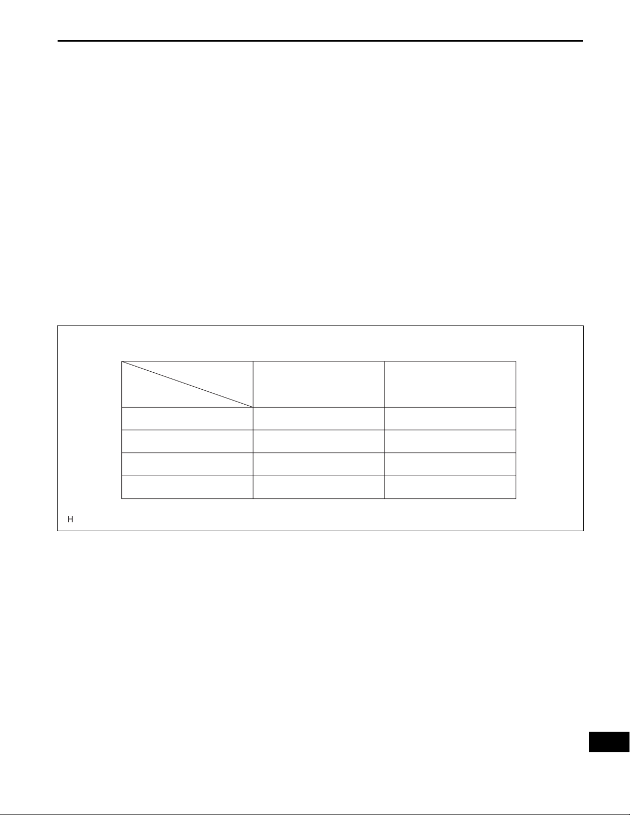
1. EXPRESSION OF IGNITION SWITCH
The type of ignition switch used on this model differs
according to the specifications of the vehicle.
The expressions listed in the table below are used in this
section.
AX–1
Switch Type
Expression
Ignition switch off
Ignition switch on (IG)
Ignition switch on (ACC)
Engine start
Ignition Switch (Position)
LOCK
ON
ACC
START
2. The automatic transaxle is composed of highly
precision-finished parts which need careful
inspection before reassembly. Even a small nick
could cause fluid leakage or affect the performance.
The instructions here are organized so that you work
on only one component group at a time. This will
help avoid confusion caused by similar-looking
parts of different sub-assemblies being on your
workbench at the same time. The component groups
are inspected and repaired from the converter
housing side. Complete the inspection, repair and
Engine Switch (Condition)
Off
On (IG)
On (ACC)
Start
E116900E03
AX

AX
AX–2
U250E AUTOMATIC TRANSAXLE – AUTOMATIC TRANSAXLE SYSTEM
reassembly before proceeding to the next
component group as much as possible. If a defect is
found in a certain component group during
reassembly, inspect and repair this group
immediately. If a component group cannot be
assembled because some parts are being ordered,
be sure to keep all parts of the group in a separate
container while proceeding with disassembly,
inspection, repair and reassembly of other
component groups. Recommended: ATF WS
3. All disassembled parts should be washed clean and
any fluid passages and holes should be blown
through with compressed air.
4. Dry all parts with compressed air. Never use a shop
rag or a piece of cloth to dry them.
5. When using compressed air, always aim away from
yourself to prevent accidentally spraying ATF or
kerosene in your face.
6. Only recommended automatic transaxle fluid or
kerosene should be used for cleaning.
7. After cleaning, the parts should be arranged in the
correct order for efficient inspection, repair, and
reassembly.
8. When disassembling a valve body, be sure to match
each valve together with the corresponding spring.
9. New discs for the brakes and clutches that are to be
used for replacement must be soaked in ATF for at
least 15 minutes before reassembly.
10. All oil seal rings, clutch discs, clutch plates, rotating
parts, and sliding surfaces should be coated with
ATF prior to reassembly .
11. All gaskets and rubber O-rings should be replaced
with new ones.
12. Do not apply adhesive cements to gaskets and
similar parts.
13. Make sure that the ends of a snap ring are not
aligned with one of the cutouts and are installed in
the groove correctly.
14. When replacing a worn bushing, the sub-assembly
containing the bushing must also be replaced.
15. Check thrust bearings and races for wear or
damage. Replace them as necessary.
16. When working with FIPG material, you must observe
the following:
• Using a razor blade and a gasket scraper, remove all
the old packing (FIPG) material from the gasket
surface.
• Thoroughly clean all components to remove any
loose material.
• Clean both sealing surfaces with a non-residue
solvent.

U250E AUTOMATIC TRANSAXLE – AUTOMATIC TRANSAXLE SYSTEM
• Parts must be reassembled within 10 minutes of
application. Otherwise, the packing (FIPG) material
must be removed and reapplied.
AX–3
AX

AX–4
U250E AUTOMATIC TRANSAXLE – AUTOMATIC TRANSAXLE SYSTEM
DEFINITION OF TERMS
Term Definition
Monitor description Description of what the ECM monitors and how it detects malfunctions (monitoring purpose and its details).
Related DTCs Diagnostic code
Preconditions that allow the ECM to detect malfunctions.
Typical enabling condition
Sequence of operation
Required sensor/components The sensors and components that are used by the ECM to detect malfunctions.
Frequency of operation
Duration
Malfunction thresholds Beyond this value, the ECM will conclude that there is a malfunction and set a DTC.
MIL operation
Component operating range
With all preconditions satisfied, the ECM sets the DTC when the monitored value(s) exceeds the
malfunction threshold(s).
The priority order that is applied to monitoring, if multiple sensors and components are used to detect the
malfunction.
While another sensor is being monitored, the next sensor or component will not be monitored until the
previous monitoring has concluded.
The number of times that the ECM checks for malfunctions per driving cycle.
"Once per driving cycle" means that the ECM detects malfunction only one time during a single driving
cycle.
"Continuous" means that the ECM detects malfunction every time when enabling condition is met.
The minimum time that the ECM must sense a continuous deviation in the monitored value(s) before
setting a DTC. This timing begins after the "typical enabling conditions" are met.
MIL illumination timing after a defect is detected.
"Immediately" means that the ECM illuminates MIL the instant the ECM determines that there is a
malfunction.
"2 driving cycle" means that the ECM illuminates MIL if the same malfunction is detected again in the 2nd
driving cycle.
Normal operation range of sensors and solenoids under normal driving conditions.
Use these ranges as a reference.
They cannot be used to judge if a sensor or solenoid is defective or not.
AX
U250E AUTOMATIC TRANSAXLE – AUTOMATIC TRANSAXLE SYSTEM
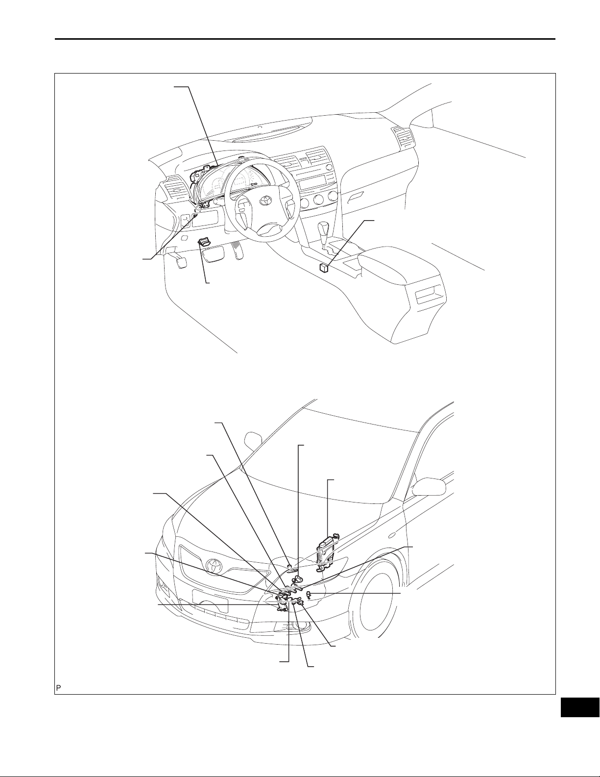
PARTS LOCATION
COMBINATION METER
- MIL (MALFUNCTION
INDICATOR LAMP)
STOP LIGHT
SWITCH
ASSEMBLY
AX–5
TRANSMISSION CONTROL SWITCH
DLC3
(DATA LINK CONNECTOR 3)
SPEED SENSOR
SHIFT SOLENOID VALVE
SHIFT SOLENOID
VALVE
SHIFT SOLENOID
VALVE
PARK / NEUTRAL
POSITION SWITCH
SL3
SR
SHIFT SOLENOID VALVE
(NC)
SLT
S4
SPEED SENSOR
ECM
SHIFT SOLENOID VALVE
SHIFT SOLENOID VALVE
(NT)
TRANSMISSION WIRE
(ATF TEMPERATURE SENSOR)
SHIFT SOLENOID VALVE
DSL
SL2
SL1
C136787E01
AX
AX–6
U250E AUTOMATIC TRANSAXLE – AUTOMATIC TRANSAXLE SYSTEM
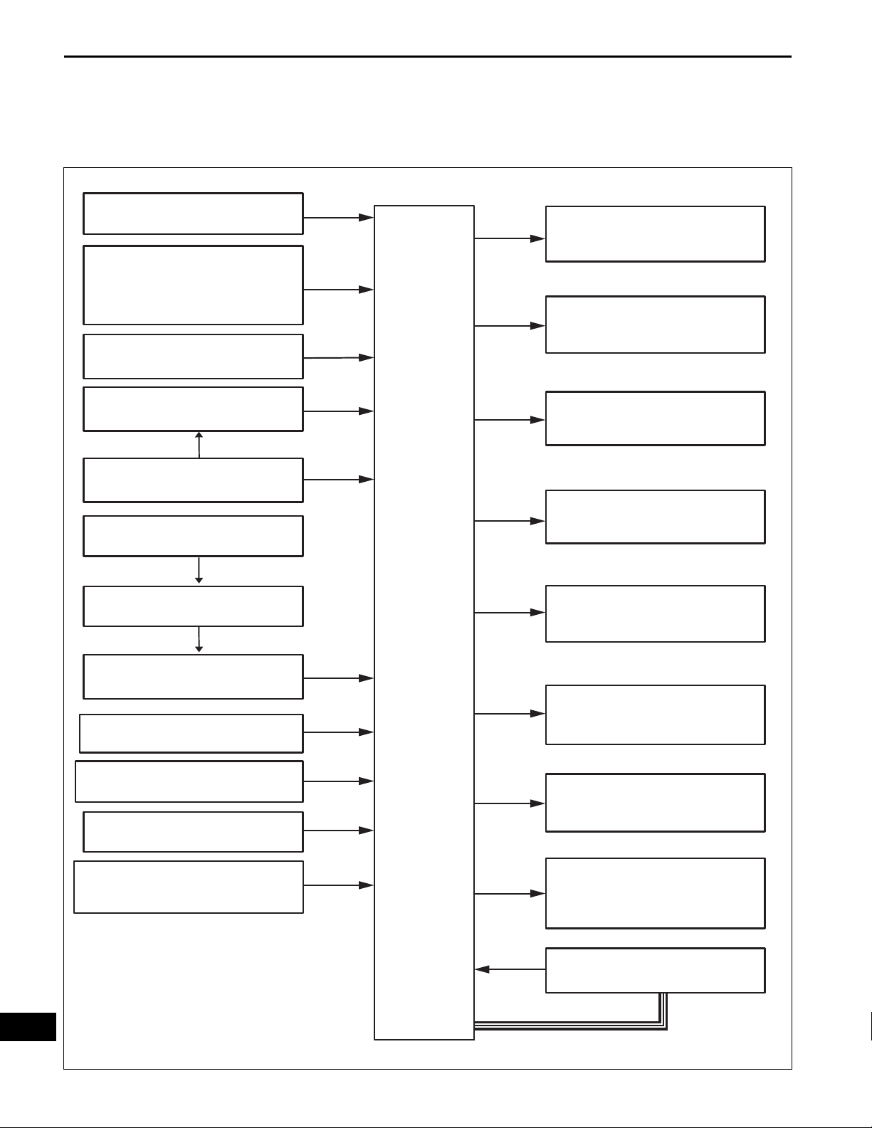
SYSTEM DIAGRAM
The configuration of the electronic control system in the
U250E automatic transaxles is as shown in the following
chart.
Crankshaft Position Sensor
Engine Coolant Temperature
Throttle Position Sensor
Transmission Control Switch
(D ←→ 4 and 2 ←→ L Position)
Park/Neutral Position Switch
Speed Sensor
Skid Control ECU
NE
THW
VTA1, 2
VC
4, L
NSW, P
R, D, 3, 2
ECM
SL1
SL2
SL3
SLT
S4
Shift Solenoid Valve SL1
Shift Solenoid Valve SL2
Shift Solenoid Valve SL3
Shift Solenoid Valve SLT
Shift Solenoid Valve S4
AX
Combination Meter
Speed Sensor NC
Speed Sensor NT
Stop Light Switch Assembly
ATF (Automatic Transmission Fluid)
SPD
NC
NT
STP
TH01
DSL
SR
W
TC
Shift Solenoid Valve DSL
Shift Solenoid Valve SR
MIL (Malfunction Indicator Light)
DLC3 (Data Link Connector 3)
CAN
C136788E01

U250E AUTOMATIC TRANSAXLE – AUTOMATIC TRANSAXLE SYSTEM
SYSTEM DESCRIPTION
1. SYSTEM DESCRIPTION
(a) The ECT (Electronic controlled automatic
transmission/transaxle) is an automatic
transmission/transaxle that electronically controls
shift timing using the ECM. The ECM detects
electrical signals that indicate engine and driving
conditions, and controls the shift point, based on
driver habits and road conditions. As a result, fuel
efficiency and power transmission performance are
improved.
Shift shock has been reduced by controlling the
engine and transmission simultaneously.
In addition, the ECT has features such as follows:
• Diagnostic function.
• Fail-safe function when a malfunction occurs.
AX–7
AX
AX–8
1
NEXT
2
NEXT
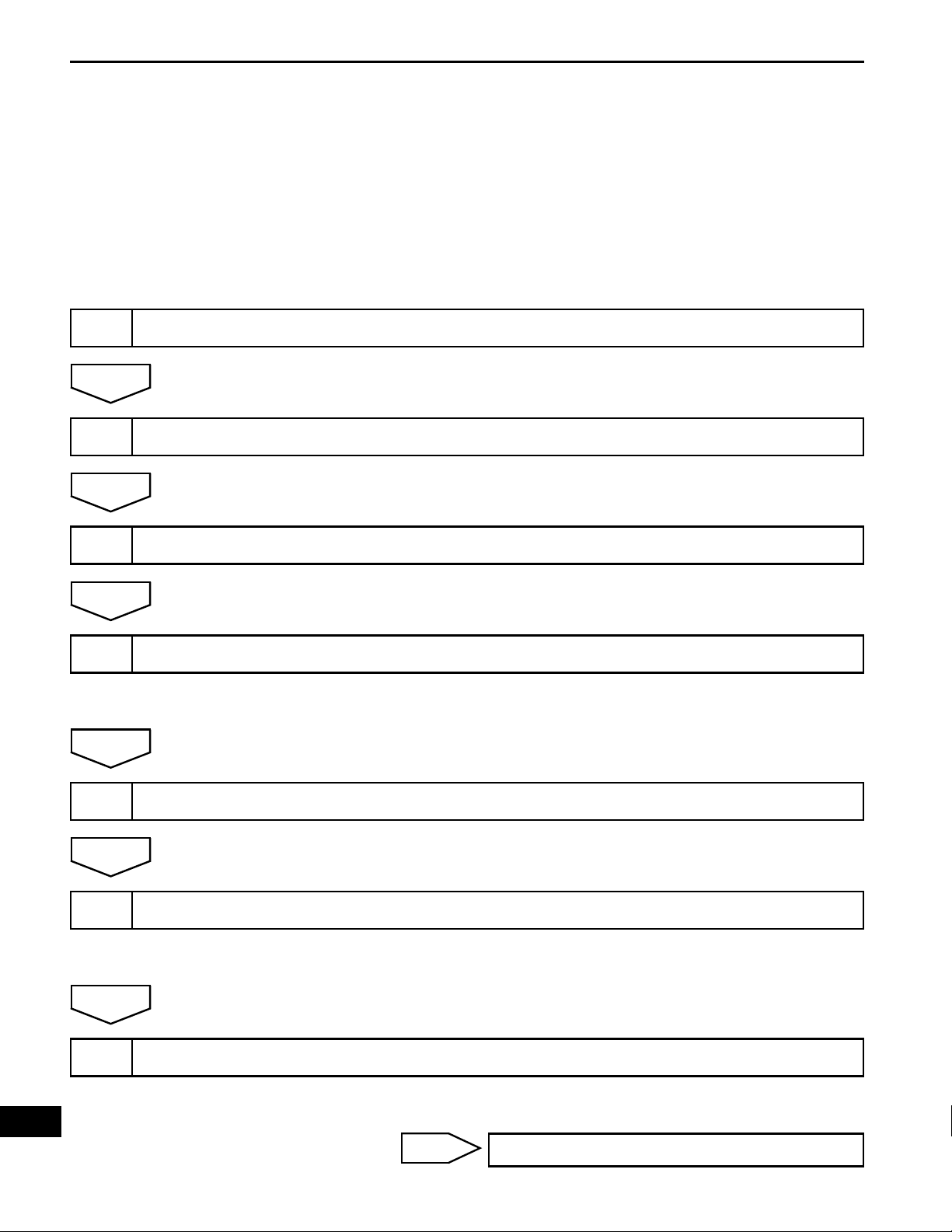
U250E AUTOMATIC TRANSAXLE – AUTOMATIC TRANSAXLE SYSTEM
HOW TO PROCEED WITH
TROUBLESHOOTING
HINT:
• The ECM of this system is connected to the CAN and
multiplex communication system. Therefore, before
starting troubleshooting, make sure to check that there is
no trouble in the CAN and multiplex communication
systems.
• The intelligent tester can be used at steps 3, 4, 6, and 9.
Vehicle Brought to Workshop
Customer Problem Analysis
3
NEXT
4
NEXT
5
NEXT
6
Connect the OBD II scan tool or intelligent tester to DLC3
Check and Clear DTCs and Freeze Frame Data
HINT:
(See page AX-28).
Visual Inspection
Setting the Check Mode Diagnosis
HINT:
(See page AX-29).
AX
NEXT
7
Problem Symptom Confirmation
HINT:
(See page AX-9).
Symptom does not occur: Go to step 8
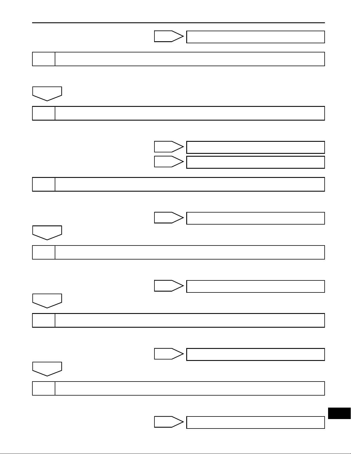
8
NEXT
9
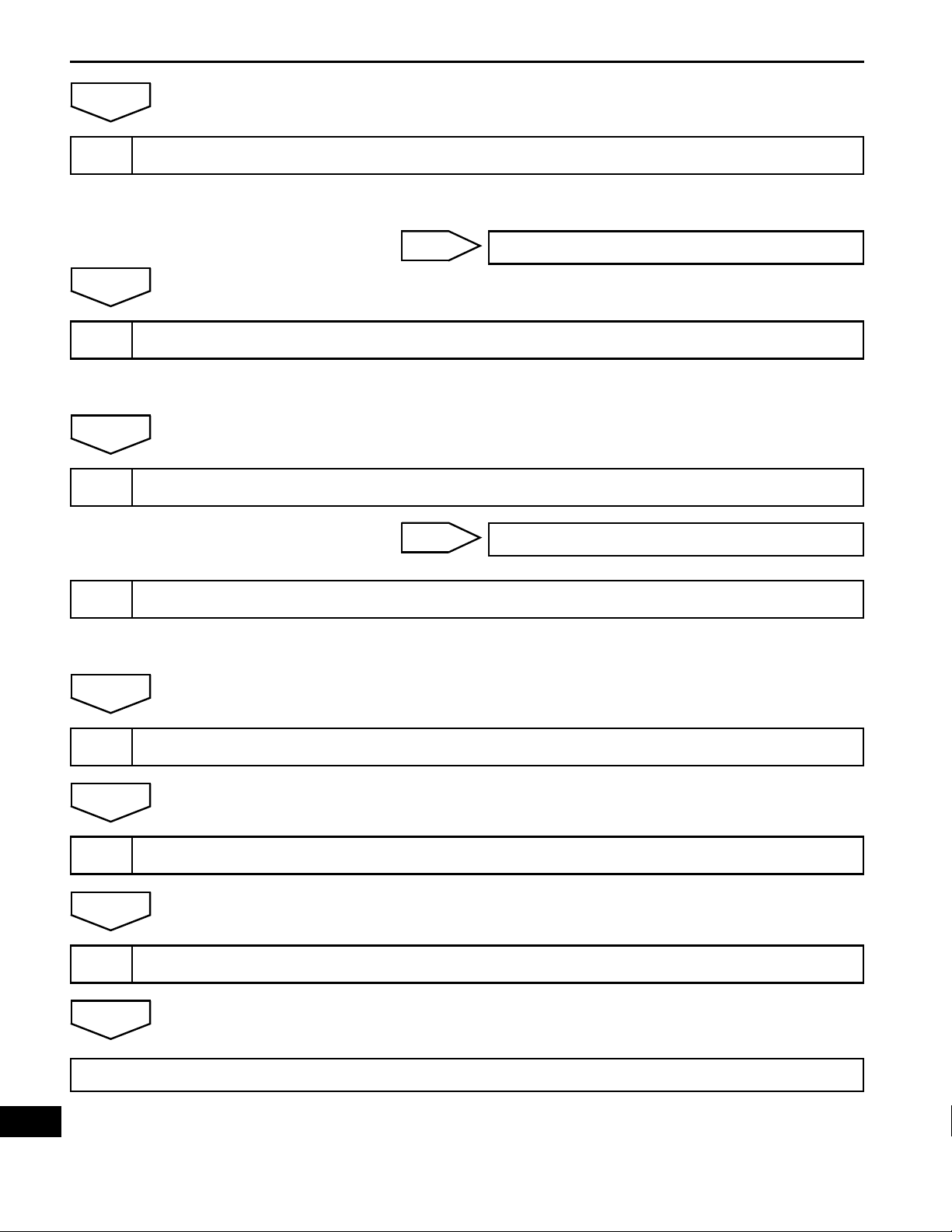
U250E AUTOMATIC TRANSAXLE – AUTOMATIC TRANSAXLE SYSTEM
Symptom Simulation
DTC Check
AX–9
Symptom occurs: Go to step 9
HINT:
(See page IN-45).
HINT:
(See page AX-28).
DTC is not output: Go to step 10
DTC is output: Go to step 17
10
OK
11
OK
12
Basic Inspection
Mechanical System Test
Hydraulic Test
HINT:
(See page AX-123, AX-129 and AX-182).
NG
HINT:
(See page AX-12).
NG
HINT:
(See page AX-14).
Go to step 19
Go to step 16
OK
13
Manual Shifting Test
NG
HINT:
(See page AX-15).
NG
Go to step 16
Go to step 15
AX
AX–10
OK
U250E AUTOMATIC TRANSAXLE – AUTOMATIC TRANSAXLE SYSTEM
14
OK
15
NEXT
16
17
Problem Symptoms Table Chapter 1
HINT:
(See page AX-19).
NG
Problem Symptoms Table Chapter 2
HINT:
(See page AX-19).
Part Inspection
DTC Chart
Go to step 18
Go to step 19
NEXT
18
NEXT
19
NEXT
20
NEXT
End
HINT:
(See page AX-35).
Circuit Inspection
Repair or Replace
Confirmation Test
AX

U250E AUTOMATIC TRANSAXLE – AUTOMATIC TRANSAXLE SYSTEM
ROAD TEST
1. PROBLEM SYMPTOM CONFIRMATION
(a) Based on the result of the customer problem
analysis, try to reproduce the symptoms. If the
problem is that the transaxle does not shift up, shift
down, or the shift point is too high or too low,
conduct the following road test referring to the
automatic shift schedule and simulate the problem
symptoms.
2. ROAD TEST
NOTICE:
Perform the test at the A TF (Automatic Transmission
Fluid) temperature 50 to 80°C (122 to 176°F) in the
normal operation.
(a) D position test:
Shift into the D position and fully depress the
accelerator pedal and check the following points.
(1) Check up-shift operation.
Check that 1 → 2, 2 → 3, 3 → 4 and 4 → 5th upshifts take place, and that the shift points
conform to the automatic shift schedule (See
page SS-40).
HINT:
5th Gear Up-shift Prohibition Control
• Engine coolant temperature is 55°C (131°F)
or less and vehicle speed is at 70 km/h (43
mph) or less.
• ATF temperature is -2°C (28°F) or less.
5th and 4th Gear Lock-up Prohibition Control
• Brake pedal is depressed.
• Accelerator pedal is released.
• Engine coolant temperature is 60°C (140°F)
or less.
(2) Check for shift shock and slip.
Check for shock and slip at the 1 → 2, 2 → 3, 3
→ 4 and 4 → 5th up-shifts.
(3) Check for abnormal noise and vibration.
Check for abnormal noise and vibration when
up-shifting from 1 → 2, 2 → 3, 3 → 4, and 4 → 5
while driving with the shift lever in the D position,
and also check while driving in the lock-up
condition.
HINT:
The check for the cause of abnormal noise and
vibration must be done thoroughly as it could
also be due to loss of balance in the differential,
torque converter clutch, etc.
(4) Check kick-down operation.
Check vehicle speeds when the 2nd to 1st, 3rd
to 2nd, 4th to 3rd, and 5th to 4th kick-downs take
place while driving with the shift lever in the D
position. Confirm that each speed is within the
applicable vehicle speed range indicated in the
automatic shift schedule (See page SS-40).
AX–11
AX

AX–12
U250E AUTOMATIC TRANSAXLE – AUTOMATIC TRANSAXLE SYSTEM
(5) Check abnormal shock and slip at kick-down.
(6) Check the lock-up mechanism.
• Drive in D position (5th gear), at a steady
speed (lock-up ON).
• Lightly depress the accelerator pedal and
check that the engine speed does not change
abruptly.
HINT:
• There is no lock-up in the 1st and 2nd gear.
• 4th lock-up operates while uphill-downhill is
active in the D position.
• If there is a big jump in engine speed, there is
no lock-up.
(b) 4 (O/D OFF) position test:
Shift into the 4 position and fully depress the
accelerator pedal and check the following points.
(1) Check up-shift operation.
Check that the 1 → 2, 2 → 3 and 3 → 4 up-shift
take place and that the shift point conforms to
the automatic shift schedule (See page SS-40).
HINT:
There is no 5th up-shift in the 4 position.
(2) Check engine braking.
While driving in the 4 position and 4th gear,
release the accelerator pedal and check the
engine braking effect.
(3) Check for abnormal noise during acceleration
and deceleration, and for shock at up-shift and
down-shift.
(c) 3 position test:
Shift into the 3 position and fully depress the
accelerator pedal and check the following points.
(1) Check up-shift operation.
Check that the 1 → 2 and 2 → 3 up-shift take
place and that the shift point conforms to the
automatic shift schedule (See page SS-40).
HINT:
There is no 4th up-shift and lock-up in the 3
position.
(2) Check engine braking.
While running in the 3 position and 3rd gear,
release the accelerator pedal and check the
engine braking effect.
(3) Check for abnormal noise during acceleration
and deceleration, and for shock at up-shift and
down-shift.
AX

U250E AUTOMATIC TRANSAXLE – AUTOMATIC TRANSAXLE SYSTEM
(d) 2 position test:
Shift into the 2 position and fully depress the
accelerator pedal and check the following points.
(1) Check up-shift operation.
Check that the 1 →2 up-shift takes place and
that the shift point conforms to the automatic
shift schedule (See page SS-40).
HINT:
There is no 3rd up-shift and lock-up in the 2
position.
(2) Check engine braking.
While running in the 2 position and 2nd gear,
release the accelerator pedal and check the
engine braking effect.
(3) Check for abnormal noise during acceleration
and deceleration, and for shock at up-shift and
down-shift.
(e) L position test:
Shift into the L position and fully depress the
accelerator pedal and check the following points.
(1) Check no up-shift.
While running in the L position, check that there
is no up-shift to 2nd gear.
HINT:
There is no lock-up in the L position.
(2) Check engine braking.
While running in the L position, release the
accelerator pedal and check the engine braking
effect.
(3) Check for abnormal noise during acceleration
and deceleration.
(f) R position test:
Shift into the R position, lightly depress the
accelerator pedal, and check that the vehicle moves
backward without any abnormal noise or vibration.
CAUTION:
Before conducting this test ensure that the test
area is free from people and obstruction.
(g) P position test:
Stop the vehicle on the grade (more than 5°) and
after shifting into the P position, release the parking
brake. Then, check that the parking lock pawl holds
the vehicle in place.
(h) Uphill/downhill control function test:
(1) Check that the gear does not up-shift to the 4th
or 5th gear while the vehicle is driving uphill.
(2) Check that the gear automatically down-shifts
from 5th to 4th or from the 4th to 3rd gear when
brake is applied while the vehicle is driving
downhill.
AX–13
AX

AX–14
U250E AUTOMATIC TRANSAXLE – AUTOMATIC TRANSAXLE SYSTEM
Evaluation:
Problem Possible cause
(a) Stall engine speed is low in D position
(b) Stall engine speed is high in D position
MECHANICAL SYSTEM TESTS
1. PERFORM MECHANICAL SYSTEM TESTS
(a) Measure the stall speed.
The object of this test is to check the overall
performance of the transaxle and engine by
measuring the stall speeds in the D position.
NOTICE:
• Driving test should be done on a paved road
(a nonskid road).
• Perform the test at the normal operating ATF
(Automatic Transmission Fluid) temperature
50 to 80°C (122 to 176°F).
• Do not continuously run this test for longer
than 10 seconds.
• To ensure safety, do this test in a wide, clear
level area which provides good traction.
• The stall test should always be carried out in
pairs. One technician should observe the
conditions of wheels or wheel stoppers
outside the vehicle while the other is doing
the test.
(1) Chock the 4 wheels.
(2) Connect the intelligent tester to the DLC3.
(3) Fully apply the parking brake.
(4) Keep your left foot pressed firmly on the brake
pedal.
(5) Start the engine.
(6) Shift into the D position. Press all the way down
on the accelerator pedal with your right foot.
(7) Quickly read the stall speed at this time.
Stall speed:
2,310 +- 150 rpm
• Engine power output may be insufficient
• Stator one-way clutch not operating properly
HINT:
If the value is less than the specified value by 600 rpm or more, the
torque converter could be faulty.
• Line pressure is too low
• Forward clutch slipping
• U/D (Underdrive) brake slipping
• U/D (Underdrive) one-way clutch is not operating properly
• No.1 one-way clutch not operating properly
• Improper fluid level
AX
(b) Measure the time lag.
(1) When the shift lever is shifted while the eng ine is
idling, there will be a certain time lapse or lag
before the shock can be felt. This is used for
checking the condition of the clutch and brake.
NOTICE:
• Perform the test at the normal operating
ATF (Automatic Transmission Fluid)
temperature: 50 to 80°C (122 to 176°F).

U250E AUTOMATIC TRANSAXLE – AUTOMATIC TRANSAXLE SYSTEM
• Be sure to allow 1 minute interval between
tests.
• Perform the test three times, and measure
the time lags. Calculate the average value
of the three time lags.
(2) Connect the intelligent tester to the DLC3.
(3) Fully apply the parking brake.
(4) Start and warm up the engine and check idle
speed.
Idle speed:
approx. 700 rpm (In N position and A/C
OFF)
(5) Shift the lever from N to D position. Using a stop
watch, measure the time from when the lever is
shifted until the shock is felt.
Time lag:
N → D less than 1.2 seconds
(6) In the same way, measure the time lag for N →
R.
Time lag:
N → R less than 1.5 seconds
Evaluation (If N → D or N → R time lag is longer than the specified):
Problem Possible cause
• Line pressure is too low
• Forward clutch worn
N → D time lag is longer
N → R time lag is longer
• No.1 one-way clutch is not operating properly
• U/D (Underdrive) one-way clutch is not operating
• U/D (Underdrive) brake worn
• Line pressure is too low
• Reverse clutch worn
• 1st and reverse brake worn
• U/D (Underdrive) brake worn
AX–15
AX
AX–16
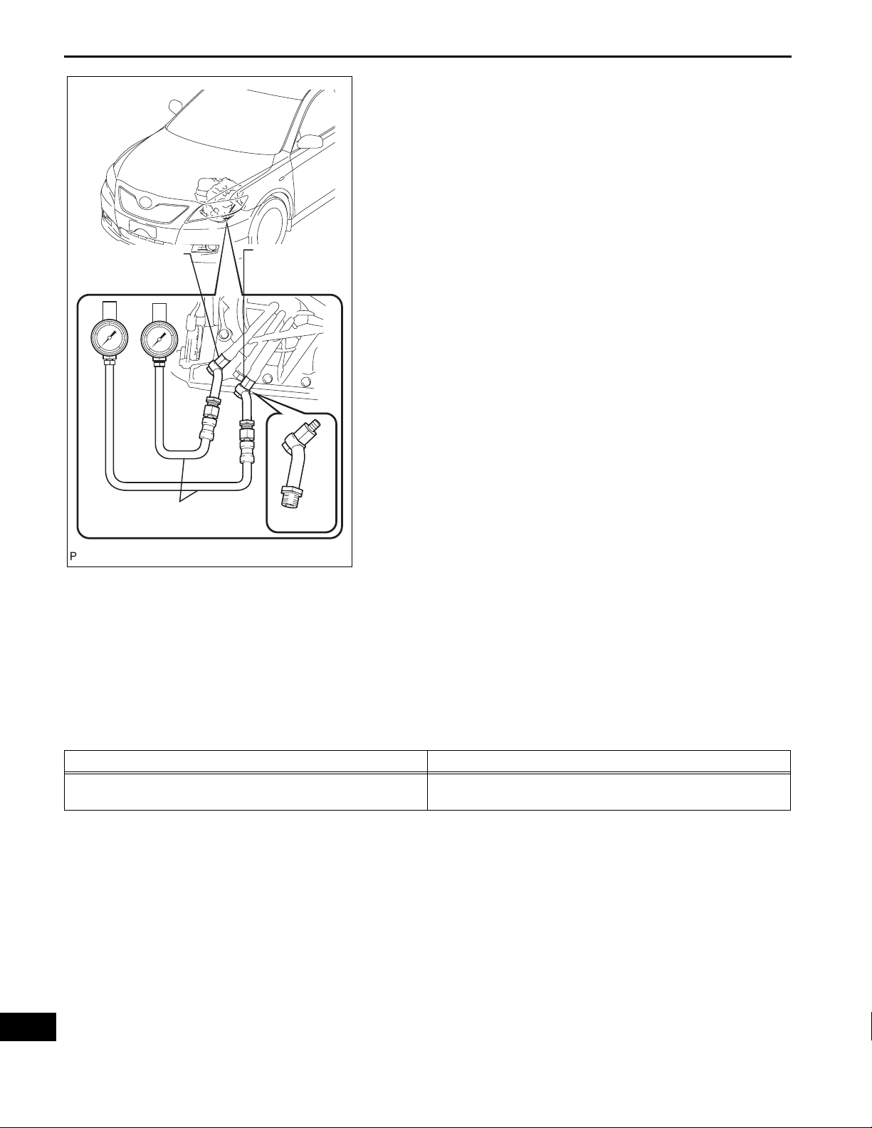
Test Plug A:
D Position (CO)
U250E AUTOMATIC TRANSAXLE – AUTOMATIC TRANSAXLE SYSTEM
SST
Specified line pressure:
Condition
Test Plug B:
R Position (C2)
Idling
SST
C109078E01
HYDRAULIC TEST
1. PERFORM HYDRAULIC TEST
(a) Measure the line pressure.
NOTICE:
• Perform the test at the normal operating ATF
(Automatic Transmission Fluid) temperature:
50 to 80°C (122 to 176°F).
• The line pressure test should always be
carried out in pairs. One technician should
observe the conditions of wheels or wheel
stoppers outside the vehicle while the other
is performing the test.
• Be careful to prevent SST hose from
interfering with the exhaust pipe.
• This Check must be conducted after checking
and adjusting engine.
• Perform under condition that A/C is OFF.
• When conducting stall test, do not continue
more than 10 seconds.
(1) Warm up the ATF (Automatic Transmission
Fluid).
(2) Lift the vehicle up.
(3) Remove the engine under cover.
(4) Connect intelligent tester to DLC3.
(5) Remove the test plug A on the transaxle case
front left side and install the SST.
SST 09992-00095 (09992-00231, 09992-
00271)
NOTICE:
There is a difference in installation point
between D position and R position.
(6) Start the engine.
(7) Using intelligent tester, shift to D position and
hold 3rd gear by active test, and measure the
line pressure in idling.
D position kPa (kgf / cm
372 to 412 kPa
(3.8 to 4.2 kgf/cm
2
, psi)
2
, 54 to 60 psi)
AX
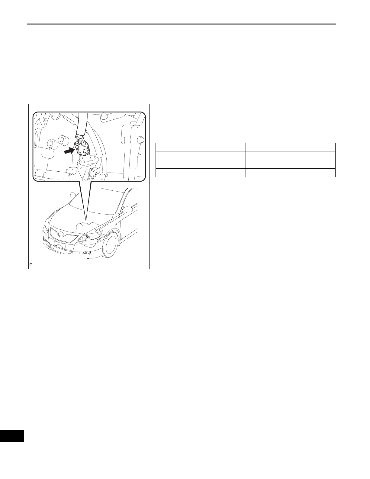
(8) Turn the ignition switch off.
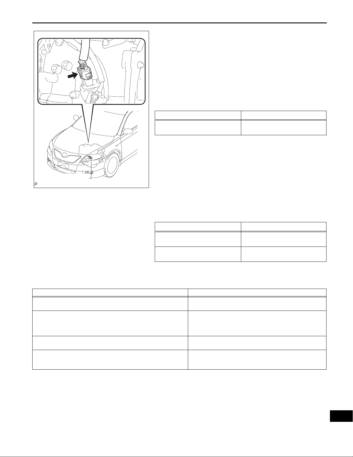
U250E AUTOMATIC TRANSAXLE – AUTOMATIC TRANSAXLE SYSTEM
Transmission Wire
C109079E01
AX–17
(9) Disconnect the connector of the transmission
wire.
HINT:
Disconnect the connector only when performing
the D position stall test.
(10)Start the engine.
(11)Firmly depress the brake pedal, shift to the D
position, depress the accelerator pedal all the
way down and check the line pressure while the
stall test is performed.
Specified line pressure:
Condition
Stall test
D position kPa (kgf / cm
931 to 1,031 kPa
(9.5 to 10.5 kgf/cm
2
2
, psi)
, 135 to 150 psi)
(12)Turn the ignition switch off.
(13)Remove the SST, install the test plug A.
(14)Remove the test plug B, install the SST and
start engine.
SST 09992-00095 (09992-00231, 09992-
00271)
(15)Connect the transmission wire connector,
depress the brake pedal firmly, shift to the R
position and check that the line pressure while
the engine is idling and during the stall test.
Specified line pressure:
Condition
Idling
Stall test
R position kPa (kgf / cm
672 to 742 kPa
(6.9 to 7.6 kgf/cm
1,768 to 1,968 kPa
(18.0 to 20.1 kgf/cm
2
2
, psi)
, 97 to 108 psi)
2
, 256 to 285 psi)
Evaluation:
Problem Possible cause
Measured values are higher than specified in all positions
Measured values are lower than specified in all positions
Pressure is low in the D position only
Pressure is low in the R position only
(16)Remove the SST, install the test plug B.
(17)Clear the DTC.
• Shift solenoid valve (SLT) defective
• Regulator valve defective
• Shift solenoid valve (SLT) defective
• Regulator valve defective
• Oil pump defective
• U/D (Underdrive) direct clutch defective
• D position circuit fluid leak
• Forward clutch defective
• R position circuit fluid leak
• Reverse clutch defective
• 1st and reverse brake defective
AX
AX–18
U250E AUTOMATIC TRANSAXLE – AUTOMATIC TRANSAXLE SYSTEM
MANUAL SHIFTING TEST
1. PERFORM MANUAL SHIFTING TEST
HINT:
• With this test, it can be determined whether the
trouble occurs in the electrical circuit or is a
mechanical problem in the transaxle.
• If any abnormalities are found in the following test, the
problem is in the transaxle itself.
(a) Disconnect the connector of the transmission wire.
(b) Drive with the transmission wire disconnected.
Shifting the shift lever in the orde r of L, 2, 3, 4 and D
position to check whether the shifting condition
changes the table below.
Shift Position Shifting Condition
L ←→ 2 No Shift (Not Change)
2 ←→ 3 Down Shift ←→ Up Shift
3 ←→ 4 ←→ D No Shift (Not Change)
HINT:
When driving with the transmission wire
disconnected, the shift lever position is in L or 2, the
gear position is held in 3rd and the shift lever
position is in 3, 4 or D, the gear position is held in
4th. However, when the shif t position is in R or P, the
operation is same as usual.
(c) Connect the connector of the transmission wire.
(d) Clear the DTC.
Transmission Wire
C109079E01
AX

U250E AUTOMATIC TRANSAXLE – AUTOMATIC TRANSAXLE SYSTEM
INITIALIZATION
1. RESET MEMORY
NOTICE:
• Perform the RESET MEMORY (AT initialization)
when replacing the automatic transaxle assembly,
engine assembly or ECM.
• The RESET MEMORY can be performed only with
the Intelligent tester.
HINT:
The ECM memorizes the condition that the ECT controls
the automatic transaxle assembly and engine assembly
according to those characteristics. Therefore, when the
automatic transaxle assembly , engine assembly, or ECM
has been replaced, it is necessary to reset the memory
so that the ECM can memorize the new information.
Reset procedure is as follows.
(a) Turn the ignition switch off.
(b) Connect the intelligent tester to the DLC3.
(c) Turn the ignition switch on (IG) position and push
the intelligent tester main switch on.
(d) Select the item "DIAGNOSIS / ENHANCED OBD
II".
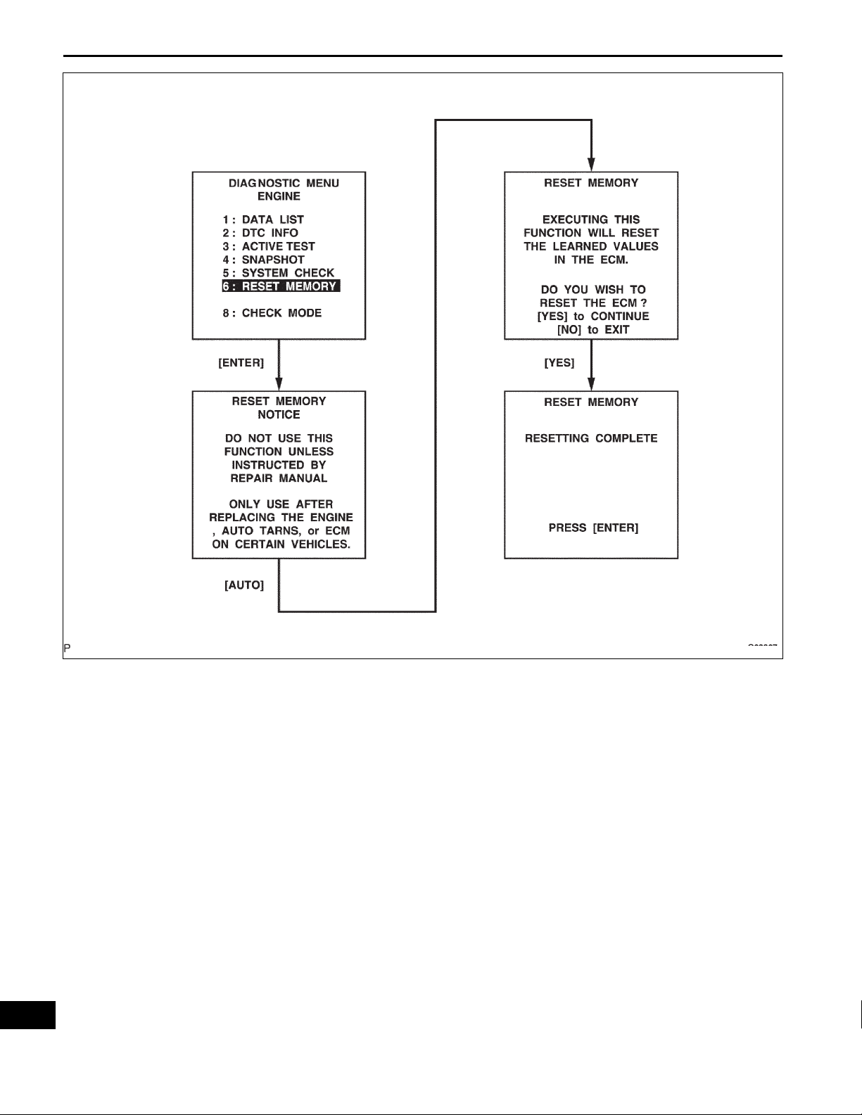
(e) Perform the reset memory procedure from the
ENGINE menu.
CAUTION:
After performing the RESET MEMORY, be sure
to perform the ROAD TEST (See page AX-9)
described earlier.
HINT:
The ECM is learned by performing the ROAD TEST.
(1) Tester menu flow:
AX–19
AX
AX–20
U250E AUTOMATIC TRANSAXLE – AUTOMATIC TRANSAXLE SYSTEM
AX
G023367

U250E AUTOMATIC TRANSAXLE – AUTOMATIC TRANSAXLE SYSTEM
MONITOR DRIVE PATTERN
1. MONITOR DRIVE PATTERN FOR ECT TEST
(a) Perform this drive pattern as one method to
simulate the detection conditions of the ECT
malfunctions. (The DTCs may not be detected due
the actual driving conditions. And some codes may
not be detected through this drive pattern.)
HINT:
Preparation for driving
• Warm up the engine sufficiently. (Engine coolant
temperature is 60°C (140°F) or higher)
• Drive the vehicle when the atmospheric
temperature is -10°C (14°F) or higher.
(Malfunction is not detected when the
atmospheric temperature is less than -10°C
(14°F))
Driving note
• Drive the vehicle through all gears.
Stop → 1st → 2nd → 3rd → 4th → 5th → 5th
(lock-up ON).
• Repeat the above driving pattern three times or
more.
NOTICE:
• The monitor status can be checked using the
OBD II scan tool or intelligent tester. When
using the intelligent tester, monitor status
can be found in the "ENHANCED OBD II /
DATA LIST" or under "CARB OBD II".
• In the event that the drive pattern must be
interrupted (possibly due to traffic conditions
or other factors), the drive pattern can be
resumed and, in most cases, the monitor can
be completed.
• Perform this drive pattern on a level road as
much as possible and strictly observe the
posted speed limits and traffic laws while
driving.
AX–21
AX
AX–22
U250E AUTOMATIC TRANSAXLE – AUTOMATIC TRANSAXLE SYSTEM
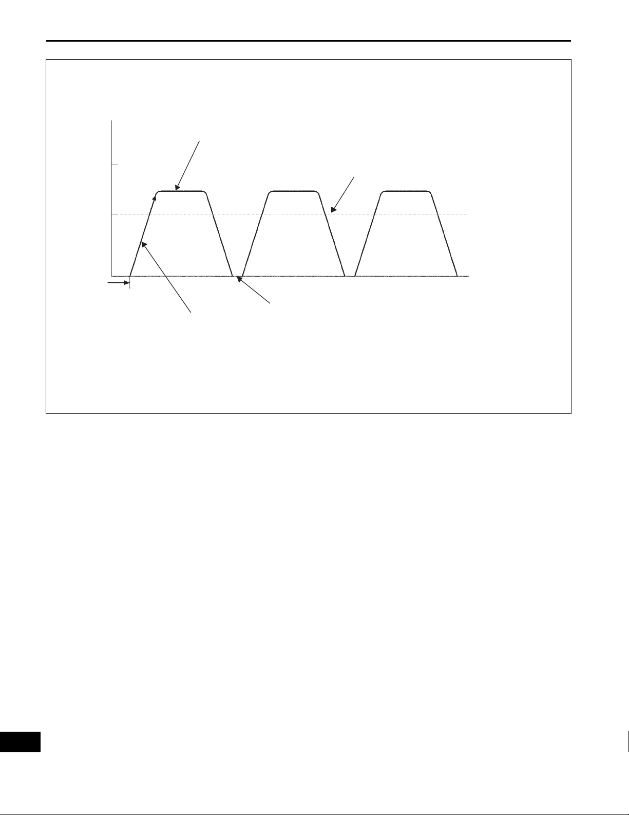
Vehicle Speed
Maintain a constant speed or gradual acceleration (with the throttie open) for 3 minutes or more.*1
Approx. 100
km/h
(62mph)
Approx. 80
km/h
(50mph)
0
Warmed up
sufficiently
Lock-up ON
Vehicle Speed
Stop (Idling)
Normal acceleration through all the
gears from 1st to 5th
G031593E12
HINT:
*1: Drive at such a speed in the uppermost gear, to
engage lock-up. The vehicle can be driven at a
speed lower than that in the above diagram under
the lock-up condition.
NOTICE:
If necessary to drive the vehicle for
approximately 30 minutes to detect DTC P0711
(ATF temperature sensor malfunction).
AX

U250E AUTOMATIC TRANSAXLE – AUTOMATIC TRANSAXLE SYSTEM
PROBLEM SYMPTOMS TABLE
HINT:
• If a normal code is displayed during the diagnostic trouble
code check although the trouble still occurs, check the
electrical circuits for each symptom in the order given in
the charts on the following pages and procee d to the p age
given for troubleshooting.
• The Matrix Chart is divided into 2 chapters.
• When the circuit on which mark *1 is attached is a
malfunction, DTC could be output.
Chapter 1:
Refer to the table below when the trouble cause is considered
to be electrical the instruction "Proceed to next circuit
inspection shown on matrix chart" is given in the flow chart of
each circuit, proceed to the circuit with the next highest
number in the table to continue the check. If the trouble still
occurs even though there are no abnormalities in any of the
other circuits, check and replace the ECM.
1. Chapter 1: Electronic Circuit Matrix Chart
Symptom Suspected area See page
No down-shift (A particular gear, from 1st to 4th gear,
is not down-shifted)
No down-shift (5th -> 4th)
No up-shift (A particular gear, from 1st to 4th gear, is
not up-shifted)
No up-shift (4th -> 5th)
No lock-up
No lock-up off ECM IN-40
Shift point too high or too low
Up-shift to 5th from 4th while shift lever is in 4 position
Up-shift to 5th from 4th while engine is cold
Up-shift to 2nd from 1st while shift lever is in L position
Harsh engagement (N -> D)
Harsh engagement (Lock-up) ECM IN-40
Harsh engagement (Any driving position) ECM IN-40
Poor acceleration ECM IN-40
No kick-down ECM IN-40
Engine stalls when starting off or stopping ECM IN-40
Malfunction in shifting
ECM IN-40
1. Transmission control switch (4 <--> D position) circuit *1 AX-39
2. Shift solenoid valve (S4) circuit *1 AX-106
3. ECM IN-40
ECM IN-40
1. Transmission control switch (4 <--> D position) circuit *1 AX-39
2. Shift solenoid valve (S4) circuit *1 AX-106
3. ECM IN-40
1. Stop light switch circuit *1 AX-60
2. Engine coolant temp. sensor circuit *1 ES-53
3. ECM IN-40
1. Throttle position sensor circuit *1 ES-53
2. ECM IN-40
1. Transmission control switch (4 <--> D position) circuit *1 AX-39
2. ECM IN-40
1. Engine coolant temp. sensor circuit *1 ES-53
2. ECM IN-40
1. Transmission control switch (2 <--> L position) circuit *1 AX-39
2. ECM IN-40
1. Shift solenoid valve (SL1) circuit *1 AX-73
2. ECM IN-40
1. Park/neutral position switch circuit *1 AX-39
2. ECM IN-40
AX–23
AX

AX
AX–24
U250E AUTOMATIC TRANSAXLE – AUTOMATIC TRANSAXLE SYSTEM
2. Chapter 2: On-Vehicle Repair and Off-Vehicle Repair
Symptom Suspected area See page
Vehicle does not move in any forward position and in
reverse positions
Vehicle does not move in R position
No up-shift (1st -> 2nd)
No up-shift (2nd -> 3rd)
No up-shift (3rd -> 4th)
No up-shift (4th -> 5th)
No down-shift (5th -> 4th)
No down-shift (4th -> 3rd) Valve body assembly AX-138
No down-shift (3rd -> 2nd) Valve body assembly AX-138
No down-shift (2nd -> 1st) Valve body assembly AX-138
No lock-up or No lock-up off
Harsh engagement (N -> D)
Harsh engagement (Lock-up)
Harsh engagement (N -> R)
Harsh engagement (1st -> 2nd -> 3rd -> 4th -> 5th)
Harsh engagement (1st -> 2nd)
Harsh engagement (2nd -> 3rd)
Harsh engagement (3rd -> 4th)
Harsh engagement (4th -> 5th)
1. Valve body assembly AX-138
2. U/D brake (B3) AX-204
3. Torque converter clutch AX-193
1. Valve body assembly AX-138
2. Reverse clutch (C2) AX-204
3. 1st and reverse brake (B2) AX-204
1. Valve body assembly AX-138
2. 2nd and O/D brake (B1) AX-204
1. Valve body assembly AX-138
2. Direct and O/D clutch (C0) AX-204
1. Valve body assembly AX-138
2. 2nd and O/D brake (B1) AX-204
1. Shift solenoid valve (S4) AX-295
2. Valve body assembly AX-138
3. U/D clutch (C3) AX-204
1. Shift solenoid (S4) AX-295
2. Valve body assembly AX-138
1. Shift solenoid valve (DSL) AX-295
2. Valve body assembly AX-138
3. Torque converter clutch AX-193
1. Shift solenoid valve (SL1) AX-295
2. Valve body assembly AX-138
3. C1 accumulator AX-204
4. Forward clutch (C1) AX-204
5. One-way clutch No.1 (F1) AX-204
6. U/D one-way clutch (F2) AX-204
1.Shift solenoid valve (SL2) AX-295
2. Valve body assembly AX-138
3. Torque converter clutch AX-193
1. Valve body assembly AX-138
2. C2 accumulator AX-204
3. Reverse clutch (C2) AX-204
4. 1st and reverse brake (B2) AX-204
1. Shift solenoid valve (SLT) AX-295
2. Valve body assembly AX-138
1. Valve body assembly AX-138
2. 2nd and O/D brake (B1) AX-204
1. Valve body assembly AX-138
2. C0 accumulator AX-204
3. Direct and O/D clutch (C0)
1. Valve body assembly AX-138
2. 2nd and O/D brake (B1) AX-204
1. Valve body assembly AX-138
2. C3 accumulator AX-204
3. U/D clutch (B3) AX-204
AX-204

U250E AUTOMATIC TRANSAXLE – AUTOMATIC TRANSAXLE SYSTEM
Symptom Suspected area See page
Harsh engagement (5th -> 4th)
Slip or shudder (Forward and reverse: After warm-up)
Slip or shudder (Particular position: Just after engine
starts)
Slip or shudder (R position)
Slip or shudder (1st)
Slip or shudder (2nd) 2nd and O/D b rake (B1) AX-204
Slip or shudder (3rd) Direct and O/D clutch (C0) AX-204
Slip or shudder (4th) 2nd and O/D brake (B1) AX-204
Slip or shudder (5th) U/D clutch (C3) AX-204
Shift position too high or too low Shift solenoid valve (SLT) AX-295
No engine braking (1st +- 4th: D position) U/D brake (B3) AX-204
No engine braking (1st: L (1) position)
No engine braking (2nd: 2 position)
No engine braking (3rd: 3 position) U/D brake (B3) AX-204
No kick-down Valve body assembly AX-138
Poor acceleration (All positions)
Poor acceleration (5th)
Engine stalls when starting off or stopping
1. Valve body assembly AX-138
2. B3 accumulator AX-204
1. Valve body assembly AX-138
2. Oil strainer AX-138
3. Direct and O/D clutch (C0) AX-204
4. Forward clutch (C1) AX-204
5. U/D clutch (C3) AX-204
6. 2nd and brake (B1) AX-204
7. U/D brake (B3) AX-204
8. One-way clutch No.1 (F1) AX-204
9. U/D one-way clutch (F2) AX-204
10. Torque converter clutch AX-193
Torque converter clutch AX-193
1. Reverse clutch (C2) AX-204
2. 1st and reverse brake (B2) AX-204
1. Forward clutch (C1) AX-204
2. One-way clutch No. 1 (F1) AX-204
3. U/D one-way clutch (F2) AX-204
1. Valve body assembly AX-138
2. 1st and reverse brake (B2) AX-204
1. Valve body assembly AX-138
2. 2nd and O/D brake (B1) AX-204
1. Shift solenoid valve (SLT) AX-295
2. Torque converter clutch AX-193
1. U/D clutch (C3) AX-204
2. U/D planetary gear unit AX-204
1. Shift solenoid valve (DSL) AX-295
2. Torque converter clutch AX-193
AX–25
AX
AX–26
U250E AUTOMATIC TRANSAXLE – AUTOMATIC TRANSAXLE SYSTEM
TERMINALS OF ECM
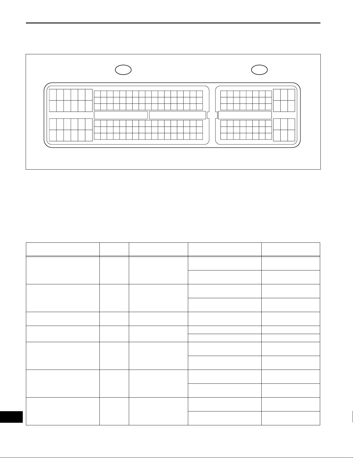
1. ECM
C24 A24
AX
HINT:
Each ECM terminal's standard voltage is shown in the
table below.
In the table, first follow the information under "Condition".
Look under "Symbols (Terminal No.)" for the terminals to
inspected. The standard voltage between the terminals
is shown under "Specific Condition".
Use the illustration above as a reference for the ECM
terminals.
Symbols (Terminals No.)
D (C24-56) - E1 (C24-104) G - W-B
R (C24-53) - E1 (C24-104) P - W-B
SPD (A24-8) - E1 (C24-104) L - W-B Speed signal Vehicle speed 20 km/h (12mph)
STP (A24-36) - E1 (C24-104) W - W-B Stop light switch signal
4 (A24-25) - E1 (C24-104) G - W-B
3 (A24-26) - E1 (C24-104) G - W-B
2 (C24-55) - E1 (C24-104) V - W-B
Wiring
Color
Terminal Description Condition Specified Condition
Ignition switch on (IG) and shift
D shift position switch
signal
R shift position switch
signal
4 shift position switch
signal
3 shift position switch
signal
2 shift position switch
signal
lever D and 4 position
Ignition switch on (IG) and shift
lever except D and 4 position
Ignition switch on (IG) and shift
lever R position
Ignition switch on (IG) and shift
lever except R position
Brake pedal is depressed 7.5 to 14 V
Brake pedal is released Below 1.5 V
Ignition switch on (IG) and shift
lever 4 position
Ignition switch on (IG) and shift
lever except 4 position
Ignition switch on (IG) and shift
lever 3 position
Ignition switch on (IG) and shift
lever except 3 position
Ignition switch on (IG) and shift
lever 2 and L position
Ignition switch on (IG) and shift
lever except 2 and L position
10 to 14 V
Below 1 V
10 to 14 V
Below 1 V
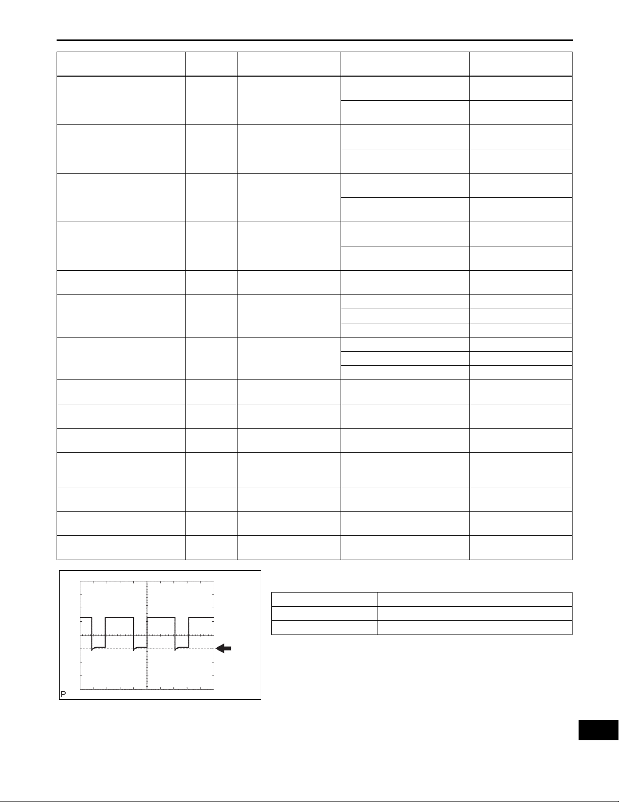
Pulse generation
(See waveform 8)
10 to 14 V
Below 1 V
10 to 14 V
Below 1 V
10 to 14 V
Below 1 V
A107881E12
U250E AUTOMATIC TRANSAXLE – AUTOMATIC TRANSAXLE SYSTEM
AX–27
Symbols (Terminals No.)
L (C24-74) - E1 (C24-104) BR - W-B
P (C24-73) - E1 (C24-104) GR - W-B Park position switch signal
N (C24-54) - E1 (C24-104) SB - W-B
NSW (C24-52) - E1 (C24-104) SB - W-B Park neutral switch signal
DSL (C24-79) - E1 (C24-104) BR - W-B DSL solenoid signal
SR (C24-80) - E1 (C24-104) G - W-B SR solenoid signal
S4 (C24-78) - E1 (C24-104) GR - W-B S4 solenoid signal
SL3+ (C24-60) - SL3- (C24-61) O - Y SL3 solenoid signal Engine idle speed
SL2+ (C24-58) - SL2- (C24-59) G - R SL2 solenoid signal Engine idle speed
SL1+ (C24-57) - SL1- (C24-77) L - L-G SL1 solenoid signal Engine idle speed
NC+ (C24-101) - NC- (C24-102) LG - P Speed sensor (NC) signal
NT+ (C24-125) - NT- (C24-124) G - W Speed sensor (NT) signal Vehicle speed 20 km/h (12mph)
SLT+ (C24-76) - SLT- (C24-75) L - W SLT solenoid signal Engine idle speed
THO1 (C24-72) - ETHO (C24-95) Y - BR
Wiring
Color
Terminal Description Condition Specified Condition
Ignition switch on (IG) and shift
L shift position switch
signal
Neutral position switch
signal
ATF temperature sensor
signal
lever L position
Ignition switch on (IG) and shift
lever except L position
Ignition switch on (IG) and shift
lever P position
Ignition switch on (IG) and shift
lever except P position
Ignition switch on (IG) and shift
lever N position
Ignition switch on (IG) and shift
lever except N position
Ignition switch on (IG) and shift
lever P and N position
Ignition switch on (IG) and shift
lever except P and N position
Vehicle speed 65 km/h (40mph),
lock-up (ON to OFF)
Ignition switch on (IG) Below 1 V
3rd, 4th or 5th gear 10 to 14 V
1st or 2nd gear Below 1 V
Ignition switch on (IG) Below 1 V
5th gear 10 to 14 V
Except 5th gear Below 1 V
Vehicle speed 30 km/h (19mph):
(3rd gear)
Engine speed 1,400 rpm
ATF temperature: 115°C (239°F)
or more
10 to 14 V
Below 1 V
10 to 14 V
Below 1 V
10 to 14 V
Below 1 V
Below 2 V
10 to 14 V
Pulse generation
(See waveform 2)
Pulse generation
(See waveform 3)
Pulse generation
(See waveform 4)
Pulse generation
(See waveform 5)
Pulse generation
(See waveform 6)
Pulse generation
(See waveform 7)
Pulse generation
(See waveform 1)
Below 1.5 V
1 ms/DIV
5 V/DIV
GND
G023426E01
(a) Waveform 1
Reference:
Terminal SLT+ - SLTTool setting 5 V/DIV, 1ms/DIV
Vehicle condition Engine idle speed
AX
AX–28
U250E AUTOMATIC TRANSAXLE – AUTOMATIC TRANSAXLE SYSTEM
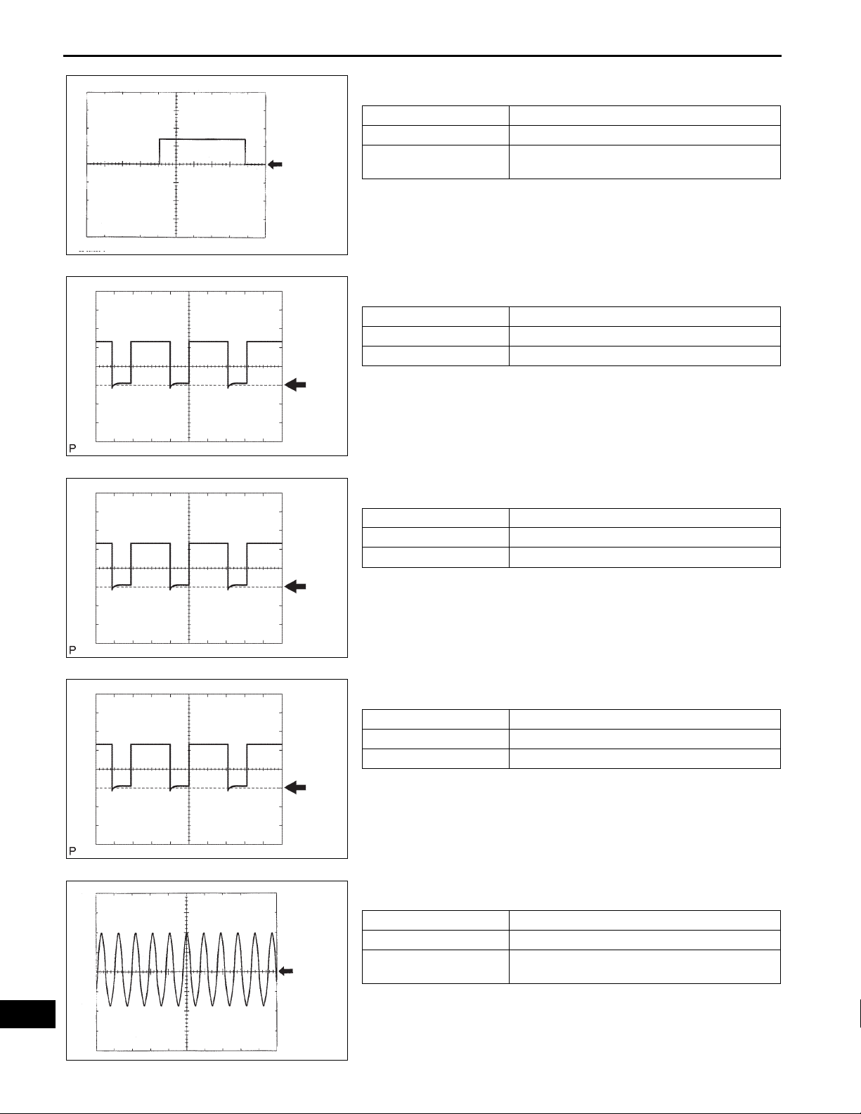
(b) Waveform 2
Reference:
Vehicle speed 65 km/h (40 mph), lock-up (ON to
OFF)
100 ms/DIV
10 V/DIV
GND
C053420E07
Terminal DSL - E1
Tool setting 10 V/DIV, 100ms/DIV
Vehicle condition
(c) Waveform 3
Reference:
1 ms/DIV
5 V/DIV
GND
G023426E01
Terminal SL3+ - SL3Tool setting 5 V/DIV, 1ms/DIV
Vehicle condition Engine idle speed
1 ms/DIV
1 ms/DIV
5 V/DIV
GND
G023426E01
5 V/DIV
GND
G023426E07
1 V/DIV
GND
(d) Waveform 4
Reference:
Terminal SL2+ - SL2Tool setting 5 V/DIV, 1ms/DIV
Vehicle condition Engine idle speed
(e) Waveform 5
Reference:
Terminal SL1+ - SL1Tool setting 5 V/DIV, 1ms/DIV
Vehicle condition Engine idle speed
(f) Waveform 6
Reference:
Terminal NC+ - NCTool setting 1 V/DIV, 1ms/DIV
Vehicle condition
Vehicle speed 30 km/h (19 mph): (3rd gear)
Engine speed 1.400 rpm
AX
1 ms/DIV
C093866E08
U250E AUTOMATIC TRANSAXLE – AUTOMATIC TRANSAXLE SYSTEM
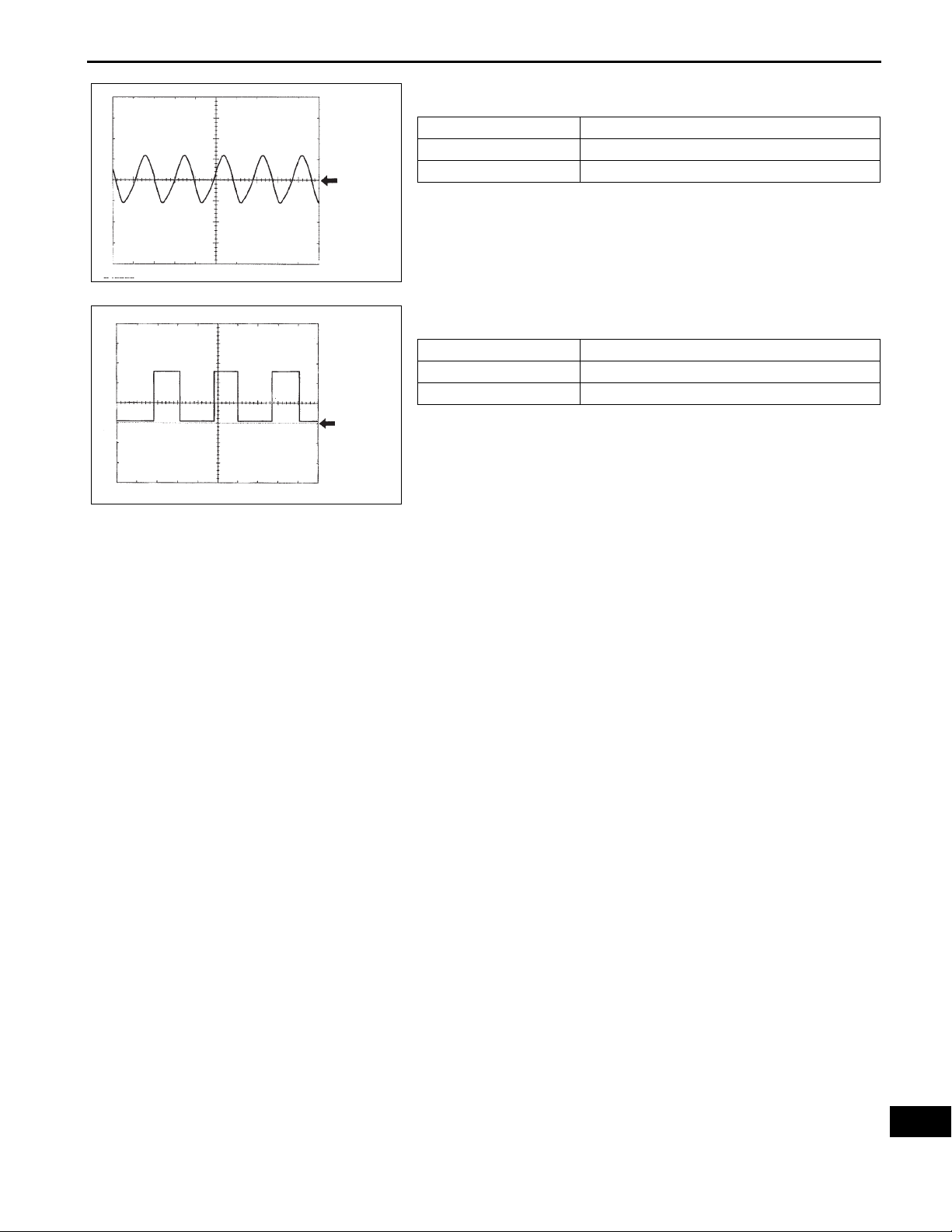
(g) Waveform 7
Reference:
0.5 ms/DIV
5 V/DIV
GND
C053419E12
Terminal NT+ - NTTool setting 5 V/DIV, 0.5ms/DIV
Vehicle condition Vehicle speed 20 km/h (12 mph)
(h) Waveform 8
5 V/DIV
Terminal SPD - E1
Tool setting 5 V/DIV, 20ms/DIV
Vehicle condition Vehicle speed 20 km/h (12 mph)
Reference:
AX–29
20 ms/DIV
GND
C053421E08
HINT:
Depending on the vehicle, the output waveform
voltage, influenced by optionally installed systems,
may become 5V.
AX
AX–30
U250E AUTOMATIC TRANSAXLE – AUTOMATIC TRANSAXLE SYSTEM
DIAGNOSIS SYSTEM
1. DESCRIPTION
(a) When troubleshooting OBD II vehicles, the only
difference from the usual troubleshooting procedure
is to connect an OBD II scan tool complying with
SAE J1987 or a intelligent tester to the vehicle, and
read off various data output from the vehicle's ECM.
(b) OBD II regulations require that the vehicle's on-
board computer illuminate the Malfunction Indicator
Lamp (MIL) on the instrument panel when the
computer detects a malfunction in the computer
itself or in the drive system components which af fect
the vehicle emissions. In addition to illuminating the
MIL when a malfunction is detected, the applicable
DTCs prescribed by SAE J2012 are recorded in the
ECM memory (See page AX-35).
FI00534
If the malfunction does not occur in 3 consecutive
trips, the MIL goes off but the DTCs remain in the
ECM memory.
Intelligent Tester
DLC3
CAN VIM
C131977E05
(c) To check the DTCs, conn ect the OBD II scan tool or
intelligent tester to the DLC3 of the vehicle. The
OBD II scan tool or intelligent tester also enables
you to erase the DTCs and check freeze frame data
and various forms of engine data (For operating
instructions, see the instruction book).
(d) The DTCs include SAE controlled codes and
Manufacturer controlled codes. SAE controlled
codes must be set as prescribed by the SAE, while
Manufacturer controlled codes can be set freely by
a manufacturer within the prescribed limits (See
page AX-35).
(e) The diagnosis system operates in "normal mode"
during the normal vehicle use. In normal mode, "2trip detection logic" is used to ensure accurate
detection of malfunction. "Check mode" is also
available to technicians as an option. In check
mode, "1-trip detection logic" is used for simulating
malfunction symptoms and increasing the system's
ability to detect malfunctions, including intermittent
malfunction.
(f) *2 trip detection logic: When a malfunction is first
detected, the malfunction is temporarily stored in
the ECM memory (1st trip). IF the ignition switch is
turned off and then turned on (IG) again, and same
malfunction is detected again, the MIL will
illuminate.
AX

U250E AUTOMATIC TRANSAXLE – AUTOMATIC TRANSAXLE SYSTEM
(g) The ECM records vehicle and driving condition
information as freeze frame data the moment a DTC
is stored. When troubleshooting, freeze frame data
can be helpful in determining whether the vehicle
was running or stopped, whether the engine was
warmed up or not, whether the air/fuel ratio was
lean or rich, as well as other data recorded at the
time of a malfunction.
AX–31
DTC set point
0.5 sec.
0.5 sec. 0.5 sec.
Freeze frame data recorded point
D1
12345678
9 10111213141516
DLC3
Terminals of DLC 3
(h) The intelligent tester displays freeze frame data
recorded at five different points: 1) 3 times before
the DTC is set, 2) once when the DTC is set, and 3)
once after the DTC is set. The data can be used to
simulate the vehicle's condition around the time of
the malfunction. The data may be helpful in
determining the cause of a malfunction. It may also
be helpful in determining whether a DTC is being
caused by a temporary malfunction.
A092901E15
2. INSPECT THE DLC3
(a) The vehicle's ECM uses ISO 15765-4for
communication. The terminal arrangement of the
DLC3 complies with SAE J1962 and matches the
ISO 15765-4format.
A082779E62
Symbol Terminal No. Name Reference Terminal Result Condition
SIL 7 Bus "+" line 5 - Signal ground Pulse generation
CG 4 Chassis ground Body ground Below 1 Ω Always
SG 5 Signal ground Body ground Below 1 Ω Always
BAT 16 Battery positive Body ground 11 to 14 V Always
CANH 6 CAN bus line CANL 54 to 69 Ω IG switch OFF*
CANH 6
CANH 6
CANL 14
CANL 14
HIGH-level CAN bus
line
HIGH-level CAN bus
lineCG
LOW-level CAN bus
line
LOW-level CAN bus
line
Battery positive 6 kΩ or higher IG switch OFF*
CG 200 Ω or higher IG switch OF F*
Battery positive 6 kΩ or higher IG switch OFF*
CG 200 Ω or higher IG switch OF F*
During
transmission
CAUTION:
*: Before measuring the resistance, leave the
vehicle as is for at least 1 minute and do not
operate the ignition switch, any other switches
or the doors.
AX

AX–32
U250E AUTOMATIC TRANSAXLE – AUTOMATIC TRANSAXLE SYSTEM
If the result is not as specified, the DLC3 may have
a malfunction. Repair or replace the harness and
connector.
HINT:
The DLC3 is the interface prepared for reading
various data from the vehicle's ECM. After
connecting the cable of the intelligent tester to the
CAN VIM, turn the ignition switch ON and turn the
tester ON. If a communication failure message is
displayed on the tester screen (on the tester:
UNABLE TO CONNECT TO VEHICLE), a problem
exists in either the vehicle or tester. In order to
identify the location of the problem, connect the
tester to another vehicle.
• If the communication is normal when the tool is
connected to another vehicle, inspect the DLC3
on the original vehicle.
• If the communication is still impossible when the
tool is connected to another vehicle, the problem
is probably in the tool itself, so consult the
Service Department listed in the tool's instruction
manual.
3. CHECK BATTERY VOLTAGE
(a) Measure the battery voltage.
Battery voltage:
11 to 14 V
If voltage is below 11 V, replace the battery before
proceeding.
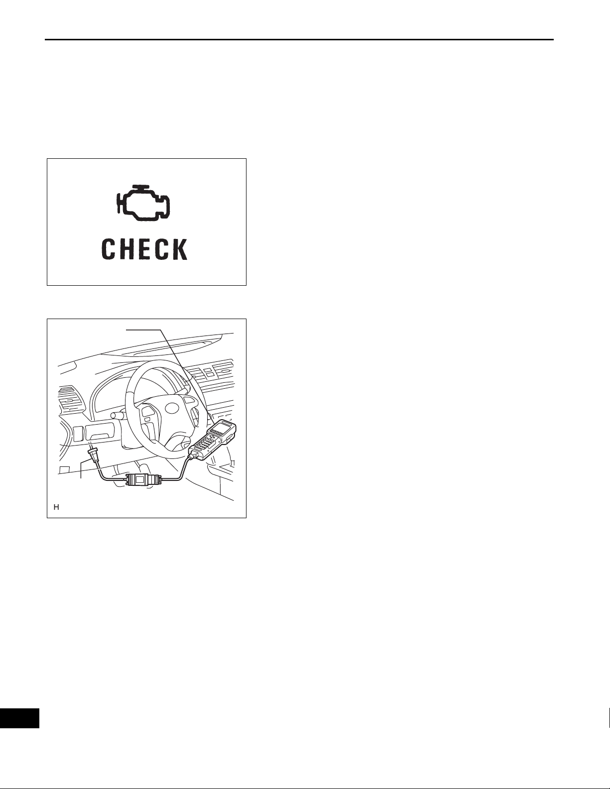
4. CHECK MIL
(a) Check that the MIL illuminates when turning the
ignition switch on (IG).
HINT:
If the MIL does not light up, troubleshoot the
combination meter.
(b) When the engine is started, the MIL should go of f. If
the lamp remains on, it means that the diagnosis
system has detected a malfunction or abnormality in
the system.
AX

U250E AUTOMATIC TRANSAXLE – AUTOMATIC TRANSAXLE SYSTEM
DTC CHECK / CLEAR
1. DTC CHECK (NORMAL MODE)
NOTICE:
When the diagnostic system is switched from the
normal mode to the check mode, all the DTCs and
freeze frame data recorded in the normal mode will
be erased. So before switching modes, always check
the DTCs and freeze frame data, and note them
down.
DTCs which are stored in the ECM can be displayed
with the intelligent tester or generic OBD II scan tool.
These scan tools can display pending DTCs and
current DTCs. Some DTC aren't stored if the ECM
doesn't detect a malfunction during consecutive
driving. However, the detected malfunction during
once driving is stored as pending DTC.
AX–33
Intelligent Tester
DLC3
CAN VIM
C131977E05
(a) Checking DTCs using the OBD II scan tool or
intelligent tester.
(1) Connect the intelligent tester to the Controller
Area Network Vehicle Interface Module (CAN
VIM). Then connect the CAN VIM to the Data
Link Connector 3 (DLC3).
(2) Turn the ignition switch on (IG).
(3) Enter the following menus: DIAGNOSIS /
ENHANCED OBD II / DTC INFO / CURRENT
CODES (or PENDING CODE).
(4) Use the OBD II scan tool or intelligent tester to
check the DTCs and freeze frame data and note
them down (For operating instructions, see the
OBD II scan tool's instruction book).
NOTICE:
When simulating symptoms with an OBD II
scan tool (excluding intelligent tester) to
check the DTCs, use the normal mode. For
codes on the DTCs chart which are subject
to "2 trip detection logic",
Turn the engine switch off after the symptom is
simulated once. Then repeat the simulation
process again. When the problem has been
simulated twice, the MIL illuminates and the
DTCs are recorded in the ECM.
2. DTC CLEAR
(a) Connect the intelligent tester to the CAN VIM. Then
connect the CAN VIM to the DLC3.
(b) Turn the ignition switch on (IG).
(c) Enter the following menus: DIAGNOSIS /
ENHANCED OBD II / DTC INFO / CLEAR CODES
and press YES.
AX

AX–34
U250E AUTOMATIC TRANSAXLE – AUTOMATIC TRANSAXLE SYSTEM
CHECK MODE PROCEDURE
HINT:
Check mode has a higher sensitivity to malfunctions and can
detect malfunction that normal mode cannot detect. Check
mode can also detect all the malfunctions that normal mode
can detect. In check mode, DTCs are detected with 1-trip
detection logic.
1. DTC CHECK (CHECK MODE)
HINT:
Intelligent tester only: Compared to the normal mode, the
check mode is more sensitive for detecting malfunctions.
Furthermore, the same diagnostic items which are
detected in the normal mode can also be detected in the
check mode.
AX
Intelligent Tester
DLC3
CAN VIM
0.13 sec. 0.13 sec.
ON
OFF
C131977E05
BR03904E17
(a) Procedure for Check Mode using the intelligent
tester.
(1) Check the initial conditions.
• Battery positive voltage 11 V or more
• Throttle valve fully closed
• Transaxle in the P or N position
• A/C switch is off
(2) Turn the ignition switch off.
(3) Connect the intelligent tester together with the
Controller Area Network Vehicle Interface
Module (CAN VIM) to the DLC3.
(4) Turn the ignition switch on (IG) and turn the
intelligent tester main switch on.
(5) Select the item "DIAGNOSIS/ENHANCED OBD
II/CHECK MODE" (Check that the MIL flashes).
NOTICE:
All DTCs and freeze frame data recorded will
be erased if: 1) the intelligent tester is used
to change the ECM from normal mode to
check mode or vice-versa; or 2) during check
mode, the ignition switch is turned from the
on (IG) to ACC position or turned OFF.
(6) Start the engine (the MIL goes off after the
engine starts).
(7) Perform "MONITOR DRIVE PATTERN" for the
ECT test (See page AX-17). (Or, simulate the
conditions of the malfunction described by the
customer).
NOTICE:
Leave the ignition switch on (IG) until you
have checked the DTCs, etc.
(8) After simulating malfunction conditions, use the
intelligent tester diagnosis selector to check the
DTCs and freeze frame data, etc.

U250E AUTOMATIC TRANSAXLE – AUTOMATIC TRANSAXLE SYSTEM
(9) When you use intelligent tester: Select the item
"DIAGNOSIS / ENHANCED OBD II / DTC INFO
/ CURRENT CODES".
(10)After checking the DTC, inspect the applicable
circuit.
(11)(See page AX-35) to confirm the details of the
DTCs.
2. DTC CLEAR
(a) Connect the intelligent tester to the CAN VIM. Then
connect the CAN VIM to the DLC3.
(b) Turn the ignition switch on (IG).
(c) Enter the following menus: DIAGNOSIS /
ENHANCED OBD II / DTC INFO / CLEAR CODES
and press YES.
AX–35
AX

AX
AX–36
Normal
SL1
Malfunction
(During driving
at 1st or 2nd)
SL1
Malfunction
(During driving
at 3rd)
SL1
Malfunction
(During driving
at 4th or 5th)
U250E AUTOMATIC TRANSAXLE – AUTOMATIC TRANSAXLE SYSTEM
FAIL-SAFE CHART
1. FAIL-SAFE
This function minimizes the loss of the ECT functions
when any malfunction occurs in a sensor or solenoid.
(a) ATF (Automatic Transmission Fluid) temperature
sensor:
When the ATF temperature sensor has a
malfunction, 5th upshift is prohibited.
(b) Counter gear speed sensor NC (Speed sensor NC):
When the counter gear speed sensor has a
malfunction, 5th upshift is prohibited.
(c) Shift solenoid valve DSL:
When the solenoid valve DSL has a malfunction, the
current to the solenoid valve is stopped.
This stops lock-up control, then fuel economy
decreases.
(d) Shift solenoid valve SL1, SL2, SL3 and S4:
Fail safe function:
If either of the shift solenoid valve circuits develops
an open or short, the ECM turns the other shift
solenoid "ON" and "OFF" in order to shift into the
gear positions shown in the table below.
Manual shifting as shown in the following table must
be done (In case of a short circuit, the ECM stops
sending the current to the short circuited solenoid).
Even if starting the engine in the fail-safe mode, the
gear position remains in the same position.
HINT:
FL: Flex Lock-up
SL1 ON OFF ON OFF OFF
Solenoid Valve
Gear Position 1st 2nd 3rd 4th 5th
Solenoid Valve
Gear Position 1st to 2nd 2nd 3rd to 2nd 4th to 2nd 5th to 2nd
Solenoid Valve
Gear Position 1st to 4th 2nd to 4th 3rd to 4th 4th 5th to 4th
Solenoid Valve
Gear Position 1st to 4th 2nd to 4th 3rd to 4th 4th 5th to 4th
SL2 ON ON OFF FL FL
SL3 OFF OFF OFF ON ON
S4 OFF OFF OFF OFF ON
SL1 OFF
SL2 ON ON OFF to ON FL to ON FL to ON
SL3 OFF OFF OFF ON to OFF ON to OFF
S4 OFF OFF OFF OFF ON to OFF
SL1 OFF
SL2 ON to FL ON to FL OFF to FL FL FL
SL3 OFF OFF OFF ON to FL ON to FL
S4 OFF to ON OFF to ON OFF to ON OFF to ON ON
SL1 OFF
SL2 ON to FL ON to FL OFF to FL FL FL
SL3 OFF to ON OFF to ON OFF to ON ON ON
S4 OFF OFF OFF OFF ON

SL2
Malfunction
SL3
Malfunction
S4 Malfunction
SL1, SL2, SL3,
and S4
Malfunction
U250E AUTOMATIC TRANSAXLE – AUTOMATIC TRANSAXLE SYSTEM
SL1 ON OFF to ON ON OFF to ON OFF to ON
Solenoid Valve
Gear Position 1st to 4th 2nd to 4th 3rd to 4th 4th 5th to 4th
Solenoid Valve
Gear Position 1st 2nd 3rd 4th 5th to 4th
Solenoid Valve
Gear Position 1st 2nd 3rd 4th 5th to 4th
Solenoid Valve
Gear Position 1st to 4th 2nd to 4th 3rd to 4th 4th 5th to 4th
SL2 OFF
SL3 OFF OFF OFF ON to OFF ON to OFF
S4 OFF to ON OFF to ON OFF to ON OFF to ON ON
SL1 ON OFF ON OFF to ON OFF to ON
SL2 ON ON OFF FL FL
SL3 OFF
S4OFFOFFOFFOFF to ONON
SL1 ON OFF ON OFF OFF
SL2 ON ON OFF FL FL
SL3 OFF OFF OFF ON ON
S4 OFF
SL1 OFF
SL2 OFF
SL3 OFF
S4 OFF
AX–37
AX

AX
AX–38
Item
STOP LIGHT SW
PNP SW [NSW]
REVERSE
DRIVE
2ND
LOW
4TH/DRIVE
3RD
U250E AUTOMATIC TRANSAXLE – AUTOMATIC TRANSAXLE SYSTEM
DATA LIST / ACTIVE TEST
1. DATA LIST
HINT:
According to the DATA LIST displayed by the intelligent
tester, you can read the value of the switch, sensor,
actuator and so on without parts removal. Reading the
DATA LIST as the first step of troubleshooting is one
method to shorten labor time.
NOTICE:
In the table below, the values listed under "Normal
Condition" are reference values. Do not depend
solely on these reference values when deciding
whether a part is faulty or not.
(a) Warm up the engine.
(b) Turn the ignition switch off.
(c) Connect the intelligent tester together with the CAN
VIM (controller area network vehicle interface
module) to the DLC3.
(d) Turn the ignition switch to the on position.
(e) Turn on the tester.
(f) Select the item "DIAGNOSIS / OBD/MOBD / ECT /
DATA LIST".
(g) According to the display on the tester, read the
"DATA LIST".
Measurement Item/
Range (display)
Stop light switch Status/
ON or OFF
PNP switch Status/
ON or OFF
PNP switch Status/
ON or OFF
PNP switch Status/
ON or OFF
PNP SW Status/
ON or OFF
PNP SW Status/
ON or OFF
PNP SW Status/
ON or OFF
PNP SW Status/
ON or OFF
Normal Condition Diagnostic Note
• Brake Pedal is depressed:
ON
• Brake Pedal is released: OFF
When the shift lever position
displayed on the Intelligent tester
differs from the actual position,
Shift lever position is;
P and N: ON
Except P and N: OFF
Shift lever position is;
R: ON
Except R: OFF
Shift lever position is;
D and 4 : ON
Except D and 4: OFF
Shift lever position is;
2 and L : ON
Except 2 and L: OFF
Shift lever position is;
L : ON
Except L: OFF
Shift lever position is;
4 : ON
Except 4: OFF
Shift lever position is;
3 : ON
Except 3: OFF
adjustment of the PNP switch or
the shift cable may be incorrect.
HINT:
When the failure still occurs even
after adjusting these parts, See
page AX-39.
-
↑
↑
↑
↑
↑
↑

U250E AUTOMATIC TRANSAXLE – AUTOMATIC TRANSAXLE SYSTEM
AX–39
Item
SHIFT
LOCK UP SOL
SOLENOID (SLT)
AT FLUID TEMP
SPD (NC)
Measurement Item/
Range (display)
Actual Gear Position/
1st, 2nd, 3rd, 4th or 5th (O/D)
Lock Up Solenoid Status/
ON or OFF
Shift Solenoid SLT Status/
ON or OFF
ATF Temp. Sensor Value/
min.: -40°C (-40°F)
max.: 215°C (419°F)
Counter Gear Speed/
display: 50 r/min
Normal Condition Diagnostic Note
Shift Lever Position is;
•L: 1st
• 2: 1st or 2nd
• 3: 1st, 2nd or 3rd
• 4: 1st, 2nd, 3rd or 4th
• D (O/D ON): 1st, 2nd, 3rd, 4th
or 5th
• Lock Up: ON
• Except Lock Up: OFF
• Accelerator pedal is
depressed: OFF
• Accelerator pedal is released:
ON
• After Stall Test;
Approx. 80°C (176°F)
• Equal to ambient temperature
when cold soak
HINT:
3rd when shift lever position is D
position (After warming up the
engine);
• Intermediate shaft speed
(NC) becomes close to the
engine speed.
If the value is "-40°C (-40°F)" or
"215°C (419°F)", ATF temp.
sensor circuit is opened or
shorted.
2. ACTIVE TEST
HINT:
Performing the ACTIVE TEST using the intelligent tester
allows the relay, VSV, actuator and so on to operate
without parts removal. Performing the ACTIVE TEST as
the first step of troubleshooting is one method to shorten
labor time.
It is possible to display the DATA LIST during the
ACTIVE TEST.
(a) Warm up the engine.
(b) Turn the ignition switch off.
(c) Connect the intelligent tester together with the CAN
VIM (controller area network vehicle interface
module) to the DLC3.
(d) Turn the ignition switch to the ON position.
(e) Push the "ON" button of the intelligent tester.
(f) Select the item "DIAGNOSIS / OBD/MOBD / ECT /
ACTIVE TEST".
(g) According to the display on tester, perform the
"ACTIVE TEST".
Item Test Details Diagnostic Note
[Test Details]
Operate the shift solenoid valve and set the each shift position by
yourself.
SHIFT
[Vehicle Condition]
•IDL: ON
• Less than 50 km/h (31 mph)
[Others]
• Press "→" button: Shift up
• Press "←" button: Shift down
Possible to check the operation of
the shift solenoid valves.
-
-
-
-
AX

AX–40
Item Test Details Diagnostic Note
LOCK UP
SOLENOID (SL1)
SOLENOID (SL2)
SOLENOID (SL3)
SOLENOID (S4)
SOLENOID (SR)
SOLENOID (DSL)
SOLENOID (SLT)
U250E AUTOMATIC TRANSAXLE – AUTOMATIC TRANSAXLE SYSTEM
[Test Details]
Control the shift solenoid DSL to set the automatic transaxle to the
lock-up condition.
[Vehicle Condition]
• Vehicle Speed: 60 km/h (37 mph) or more
[Test Details]
Operate the shift solenoid SL1
[Vehicle Condition]
• Vehicle Stopped.
• Shift lever P or N position
[Test Details]
Operate the shift solenoid SL2
[Vehicle Condition]
• Vehicle Stopped.
• Shift lever P or N position
[Test Details]
Operate the shift solenoid SL3
[Vehicle Condition]
• Vehicle Stopped.
• Shift lever P or N position
[Test Details]
Operate the shift solenoid S4
[Vehicle Condition]
• Vehicle Stopped.
• Shift lever P or N position
[Test Details]
Operate the shift solenoid SR
[Vehicle Condition]
• Vehicle Stopped.
• Shift lever P or N position
[Test Details]
Operate the shift solenoid DSL
[Vehicle Condition]
• Vehicle Stopped.
• Shift lever P or N position
[Test Details]
Operate the shift solenoid SLT and raise the line pressure.
[Vehicle Condition]
*
• Vehicle Stopped.
•IDL: ON
HINT:
OFF: Line pressure up (When the active test of "SOLENOID (SLT)"
is performed, the ECM commands the SLT solenoid to turn off).
ON: No action (normal operation)
Possible to check the DSL
operation.
-
-
-
-
-
-
-
AX
*
: "SOLENOID (SLT)" in the ACTIVE TEST is
performed to check the line pressure changes by
connecting the SST to the automatic transaxle,
which is used in the HYDRAULIC TEST (See page
AX-14) as well.
HINT:
The pressure values in ACTIVE TEST and
HYDRAULIC TEST are different from each other.

U250E AUTOMATIC TRANSAXLE – AUTOMATIC TRANSAXLE SYSTEM
DIAGNOSTIC TROUBLE CODE CHART
If a DTC is displayed during the DTC check, check the parts
listed in the table below and proceed to the page given.
HINT:
• *1: Comes on MIL (Malfunction Indicator Lamp) light up
• *2: "DTC stored" mark means ECM memorizes the
malfunction code if the ECM detects the DTC detection
condition.
• This DTC may be output when the clutch, brake and gear
components etc. inside the automatic transmission are
damaged.
AUTOMATIC TRANSMISSION SYSTEM
DTC No. Detection Item Trouble Area MIL *1 Memory *2 See page
P0705 Transmission Range
Sensor Circuit
Malfunction (PRNDL
Input)
P0710 Transmission Fluid
Temperature Sensor
"A" Circuit
P0711 Transmission Fluid
Temperature Sensor
"A" Performance
P0712 Transmission Fluid
Temperature Sensor
"A" Circuit Low Input
P0713 Transmission Fluid
Temperature Sensor
"A" Circuit High Input
P0717 Turbine Speed
Sensor Circuit No
Signal
P0724 Brake Switch "B"
Circuit High
1. Open or short in
park/neutral position
switch circuit
2. Park/neutral
position switch
3. ECM
1. Open or short in
ATF temperature
sensor circuit
2. Transmission wire
(ATF temperature
sensor)
3. ECM
1. Transmission wire
(ATF temperature
sensor)
1. Short in ATF
temperature sensor
circuit
2. Transmission wire
(ATF temperature
sensor)
3. ECM
1. Open in ATF
temperature sensor
circuit
2. Transmission wire
(ATF temperature
sensor)
3. ECM
1. Open or short in
transmission
revolution sensor NT
(speed sensor NT)
circuit
2. Transmission
revolution sensor NT
(speed sensor NT)
3. ECM
4. Automatic
transaxle assembly
1. Short in stop light
switch circuit
2. Stop light switch
3. ECM
Comes on DTC stored AX-39
Comes on DTC stored AX-48
Comes on DTC stored AX-53
Comes on DTC stored AX-48
Comes on DTC stored AX-48
Comes on DTC stored AX-57
Comes on DTC stored AX-60
AX–41
AX

AX
AX–42
DTC No. Detection Item Trouble Area MIL *1 Memory *2 See page
P0741 Torque Converter
P0746 Pressure Control
P0748 Pressure Control
P0766 Shift Solenoid "D"
P0771 Shift Solenoid "E"
P0776 Pressure Control
P0778 Pressure Control
P0793 Intermediate Shaft
U250E AUTOMATIC TRANSAXLE – AUTOMATIC TRANSAXLE SYSTEM
Comes on DTC stored AX-63
Comes on DTC stored AX-69
Comes on DTC stored AX-73
Comes on DTC stored AX-77
Comes on DTC stored AX-81
Comes on DTC stored AX-85
Comes on DTC stored AX-90
Comes on DTC stored AX-94
Clutch Solenoid
Performance (Shift
Solenoid Valve DSL)
Solenoid "A"
Performance (Shift
Solenoid Valve SL1)
Solenoid "A"
Electrical (Shift
Solenoid Valve SL1)
Performance (Shift
Solenoid Valve S4)
Performance (Shift
Solenoid Valve SR)
Solenoid "B"
Performance (Shift
Solenoid Valve SL2)
Solenoid "B"
Electrical (Shift
Solenoid Valve SL2)
Speed Sensor "A"
1. Shift solenoid
valve DSL remains
open or closed
2. Valve body is
blocked
3. Torque converter
clutch
4. Automatic
transaxle (clutch,
brake or gear etc.)
5. Line pressure is
too low
1. Shift solenoid
valve SL1 remains
open or closed
2. Valve body is
blocked
3. Automatic
transaxle (clutch,
brake or gear etc.)
1. Open or short in
shift solenoid valve
SL1 circuit
2. Shift solenoid
valve SL1
3. ECM
1. Shift solenoid
valve S4 remains
open or closed
2. Valve body is
blocked (Brake
control valve)
3. Automatic
transmission (clutch,
brake or gear, etc.)
1. Shift solenoid
valve SR remains
open or closed
2. Valve body is
blocked
3. Automatic
transaxle (clutch,
brake or gear etc.)
1. Shift solenoid
valve SL2 remains
open or closed
2. Valve body is
blocked
3. Automatic
transaxle (clutch,
brake or gear etc.)
1. Open or short in
shift solenoid valve
SL2 circuit
2. Shift solenoid
valve SL2
3. ECM
1. Open or short in
transmission
revolution sensor NC
(speed sensor NC)
circuit
2. Transmission
revolution sensor NC
(speed sensor NC)
3. ECM

U250E AUTOMATIC TRANSAXLE – AUTOMATIC TRANSAXLE SYSTEM
DTC No. Detection Item Trouble Area MIL *1 Memory *2 See page
P0796 Pressure Control
Solenoid "C"
Performance (Shift
Solenoid Valve SL3)
P0798 Pressure Control
Solenoid "C"
Electrical (Shift
Solenoid Valve SL3)
P0982 Shift Solenoid "D"
Control Circuit Low
(Shift Solenoid Valve
S4)
P0983 Shift Solenoid "D"
Control Circuit High
(Shift Solenoid Valve
S4)
P0985 Shift Solenoid "E"
Control Circuit Low
(Shift Solenoid Valve
SR)
P0986 Shift Solenoid "E"
Control Circuit High
(Shift Solenoid Valve
SR)
P2714 Pressure Control
Solenoid "D"
Performance (Shift
Solenoid Valve SLT)
P2716 Pressure Control
Solenoid "D"
Electrical (Shift
Solenoid Valve SLT)
P2769 Torque Converter
Clutch Solenoid
Circuit Low (Shift
Solenoid Valve DSL)
P2770 Torque Converter
Clutch Solenoid
Circuit High (Shift
Solenoid Valve DSL)
1. Shift solenoid
valve SL3 remains
open or closed
2. Valve body is
blocked
3. Automatic
transaxle (clutch,
brake or gear etc.)
1. Open or short in
shift solenoid valve
SL3 circuit
2. Shift solenoid
valve SL3
3. ECM
1. Short in shift
solenoid valve S4
circuit
2. Shift solenoid
valve S4
3. ECM
1. Open in shift
solenoid valve S4
circuit
2. Shift solenoid
valve S4
3. ECM
1. Short in shift
solenoid valve SR
circuit
2. Shift solenoid
valve SR
3. ECM
1. Open in shift
solenoid valve SR
circuit
2. Shift solenoid
valve SR
3. ECM
1. Shift solenoid
valve SLT remains
closed
2. Valve body is
blocked
3. Automatic
transaxle (clutch,
brake or gear etc.)
1. Open or short in
shift solenoid valve
SLT circuit
2. Shift solenoid
valve SLT
3. ECM
1. Short in shift
solenoid valve DSL
circuit
2. Shift solenoid
valve DSL
3. ECM
1. Open in shift
solenoid valve DSL
circuit
2. Shift solenoid
valve DSL
3. ECM
Comes on DTC stored AX-98
Comes on DTC stored AX-102
Comes on DTC stored AX-106
Comes on DTC stored AX-106
Comes on DTC stored AX-109
Comes on DTC stored AX-109
Comes on DTC stored AX-112
Comes on DTC stored AX-116
Comes on DTC stored AX-120
Comes on DTC stored AX-120
AX–43
AX

AX–44
U250E AUTOMATIC TRANSAXLE – AUTOMATIC TRANSAXLE SYSTEM
DTC P0705
Transmission Range Sensor Circuit Malfunction (PRNDL Input)
DESCRIPTION
The park/neutral position switch detects the shift lever position and sends signals to the ECM.
DTC No. DTC Detection Condition Trouble Area
(A) Any 2 or more signals of the following are ON
simultaneously (2-trip detection logic)
• P input signal is ON.
• N input signal is ON.
• R input signal is ON.
• D input signal is ON.
• 3 input signal is ON.
• 2 input signal is ON.
(B) Any 2 or more signals of the following are ON
simultaneously (2-trip detection logic)
• NSW input signal is ON.
P0705
• R input signal is ON.
• D input signal is ON.
• 3 input signal is ON.
• 2 input signal is ON.
(C) All switches are OFF simultaneously for NSW, P, R, N, D,
3 and 2 positions (2-trip detection logic).
(D) Both 1 and 2 are met (2-trip detection logic)
1. One of the following is met
(a) NSW input signal is ON.
(b) P input signal is ON.
(c) N input signal is ON.
(d) R input signal is ON
2. One of the following is met
(a) 4 input signal is ON.
(b) L input signal is ON.
• Open or short in park / neutral position switch circuit
• Park / neutral position switch
•ECM
AX
MONITOR DESCRIPTION
These DTCs indicate a problem with the park/neutral position switch and the wire harness in the park/
neutral position switch circuit.
The park/neutral position switch detects the shift lever position and sends a signal to the ECM.
For security, the park/neutral position switch detects the shift lever position so that engine can be started
only when the shift lever is in the P or N position
The park/neutral position switch sends a signal to the ECM according to the shift position (P, R, N or D).
The ECM determines that there is a problem with the switch or related parts if in receives more than 1
position signal simultaneously. The ECM will turn on the MIL and store the DTC.
MONITOR STRATEGY
Related DTCs P0705: Park/neutral position switch/Verify switch input
Required sensors/Components Park/neutral position switch
Frequency of operation Continuous
Duration 2 sec.
MIL operation 2 driving cycles
Sequence of operation None
TYPICAL ENABLING CONDITIONS
All:
The monitor will run whenever this DTC is not present. None
Ignition switch ON
Battery voltage 10.5 V or more

U250E AUTOMATIC TRANSAXLE – AUTOMATIC TRANSAXLE SYSTEM
TYPICAL MALFUNCTION THRESHOLDS
1. One of the following conditions is met: Condition (A), (B), (C) and (D)
Condition (A)
If 2 or more of the following signal outputs exist at the same time
P switch ON
N switch ON
R switch ON
D switch ON
3 switch ON
2 switch ON
Condition (B)
If 2 or more of the following signal outputs exist at the same time
NSW switch ON
R switch ON
D switch ON
3 switch ON
2 switch ON
AX–45
Condition (C)
All of following conditions are met
NSW switch OFF
P switch OFF
N switch OFF
R switch OFF
D switch OFF
3 switch OFF
2 switch OFF
Condition (D)
Both (i) and (ii) are met
(i) One of the following is met
NSW switch ON
P switch ON
N switch ON
R switch ON
(ii) One of the following is met
4 switch ON
L switch ON
COMPONENT OPERATING RANGE
Park/neutral Position switch The park/neutral position switch sends only one signal to the ECM.
AX

AX–46
U250E AUTOMATIC TRANSAXLE – AUTOMATIC TRANSAXLE SYSTEM
WIRING DIAGRAM
To ST Relay
C1 Park / Neutral Position Switch
N
5
RB
2
P
4
LL
8
2L
3
DL
7
51
NSSL NSSD
AT4
ATL
ECM
48
A24
STA
52
NSW
C24
55
C24
2
26
3
A24
56
D
C24
25
A24
74
C24
4
L
2
6
FL MAIN
Battery
NL
9
RL
1
PL
6
GAUGE No. 1
ALT
E31 Transmission Control Switch
AM1
AM1
4112
E23
Ignition Switch
IG1
54
C24
53
C24
73
C24 P
IG1
N
R
35
C125005E01
AX

U250E AUTOMATIC TRANSAXLE – AUTOMATIC TRANSAXLE SYSTEM
AX–47
INSPECTION PROCEDURE
HINT:
According to the DATA LIST displayed by the intelligent tester, you can read the value of the switch,
sensor, actuator and so on without parts removal. Reading the DATA LIST as the first step of
troubleshooting is one method to shorten labor time.
NOTICE:
In the table below , the values listed under "Normal Condition" are reference values. Do not depend
solely on these reference values when deciding whether a part is faulty or not.
1. READ DATA LIST
(a) Turn the ignition switch off.
(b) Connect the intelligent tester together with the CAN VIM (controller area network vehicle
interface module) to the DLC3.
(c) Turn the ignition switch on (IG).
(d) Turn on the tester.
(e) Select the item "DIAGNOSIS / OBD/MOBD / ECT / DATA LIST".
(f) According to the display on the tester, read the "DATA LIST".
Item
PNP SW [NSW] PNP SW Status / ON or OFF
REVERSE PNP SW Status / ON or OFF
DRIVE PNP SW Status / ON or OFF
2ND PNP SW Status / ON or OFF
LOW PNP SW Status / ON or OFF
4TH/DRIVE PNP SW Status / ON or OFF
3RD PNP SW Status / ON or OFF
Measurement Item / Range
(Display)
Normal Condition Diagnostic Note
When the shift lever position
Shift lever position is;
P and N: ON
Except P or N: OFF
Shift lever position is;
R: ON
Except R: OFF
Shift lever position is;
D and 4: ON
Except D and 4: OFF
Shift lever position is;
2 and L: ON
Except 2 and L: OFF
Shift lever position is;
L: ON
Except L: OFF
Shift lever position is;
4: ON
Except 4: OFF
Shift lever position is;
3: ON
Except 3: OFF
displayed on the intelligent tester
differs from the actual position,
adjustment of the PNP switch or
the shift cable may be incorrect.
When the shift lever position
displayed on the intelligent tester
differs from the actual position,
adjustment of the PNP switch or
the shift cable may be incorrect.
When the shift lever position
displayed on the intelligent tester
differs from the actual position,
adjustment of the PNP switch or
the shift cable may be incorrect.
When the shift lever position
displayed on the intelligent tester
differs from the actual position,
adjustment of the PNP switch or
the shift cable may be incorrect.
When the shift lever position
displayed on the intelligent tester
differs from the actual position,
adjustment of the PNP switch or
the shift cable may be incorrect.
When the shift lever position
displayed on the intelligent tester
differs from the actual position,
adjustment of the PNP switch or
the shift cable may be incorrect.
When the shift lever position
displayed on the intelligent tester
differs from the actual position,
adjustment of the PNP switch or
the shift cable may be incorrect.
AX

AX–48
1
U250E AUTOMATIC TRANSAXLE – AUTOMATIC TRANSAXLE SYSTEM
CHECK HARNESS AND CONNECTOR (BATTERY - PARK/NEUTRAL POSITION)
Wire Harness Side:
(Connector Front View):
C1
12
OK
CHECK HARNESS AND CONNECTOR (OUTPUT SIGNAL)
2
Wire Harness Side:
(Connector Front View):
34
98765
RB
B
C117645E06
(a) Disconnect the park/neutral position switch connector.
(b) Turn the ignition switch on (IG).
(c) Measure voltage according to the value(s) in the table
below.
Standard voltage
Tester Connection Specified Condition
2 - Body ground 10 to 14 V
NG
REPAIR OR REPLACE HARNESS OR
CONNECTOR
(a) Turn the ignition switch on (IG).
(b) Measure voltage according to the value(s) in the table
below.
Standard voltage
Tester Connection Specified Condition
4 - Body ground 10 to 14 V
AX
C1
OK
12
34
98765
C117645E07
NG
Go to step 8

U250E AUTOMATIC TRANSAXLE – AUTOMATIC TRANSAXLE SYSTEM
INSPECT PARK/NEUTRAL POSITION SWITCH ASSEMBLY
3
Switch Side:
(Connector Front View):
C1
C110340E34
AX–49
(a) Measure resistance according to the value(s) in the t able
below when the shift lever is moved to each position.
Standard resistance
Shift Position Tester Connection Specified Condition
P
Except P 10 kΩ or higher
R
Except R 10 kΩ or higher
N
Except N 10 kΩ or higher
D and 4
Except D and 4 10 kΩ or higher
3
Except 3 10 kΩ or higher
2 and L
Except 2 and L 10 kΩ or higher
2 - 6 and 4 - 5
2 - 1
2 - 9 and 4 - 5
2 - 7
2 - 3
2 - 8
Below 1 Ω
Below 1 Ω
Below 1 Ω
Below 1 Ω
Below 1 Ω
Below 1 Ω
OK
CHECK HARNESS AND CONNECTOR (PARK/NEUTRAL POSITION SWITCH - ECM)
4
Wire Harness Side:
(Connector Front View):
ECM
RN2 P D
C24
NG
REPLACE PARK/NEUTRAL POSITION
SWITCH ASSEMBLY
(a) Connect the park/neutral position switch connector.
(b) Disconnect the ECM connectors.
(c) Turn the ignition switch on (IG), and measure the voltage
according to the value(s) in the table below when the
shift lever is moved to each position.
A24
3
C136857E03
AX

AX–50
Standard voltage
Shift Position Tester Connection Specified Condition
P
Except P Below 1 V
N
Except N Below 1 V
R
Except R Below 1 V
D and 4
Except D and 4 Below 1 V
3
Except 3 Below 1 V
2 and L
Except 2 and L Below 1 V
U250E AUTOMATIC TRANSAXLE – AUTOMATIC TRANSAXLE SYSTEM
C24-73 (P) - Body ground
C24-54 (N) - Body ground
C24-53 (R) - Body ground
C24-56 (D) - Body ground
A24-26 (3) - Body ground
C24-55 (2) - Body ground
10 to 14 V
10 to 14 V
10 to 14 V
10 to 14 V
10 to 14 V
10 to 14 V
HINT:
*
: The voltage will drop slightly due to lighting up of the
back up light.
*
OK
CHECK HARNESS AND CONNECTOR (PARK/NEUTRAL POSITION SWITCH -
5
TRANSMISSION CONTROL SWITCH)
Wire Harness Side:
(Connector Front View):
E31
C110345E17
NG
REPAIR OR REPLACE HARNESS OR
CONNECTOR
(a) Disconnect the transmission control switch connector of
shift lock control unit assembly.
(b) Measure the voltage according to the value(s) in the
table below when the shift lever is moved to each
position.
Standard voltage
Shift Position Tester Connection Specified Condition
D and 4
Except D and 4 Below 1 V
2 and L
Except 2 and L Below 1 V
NG
REPAIR OR REPLACE HARNESS OR
1 - Body ground
5 - Body ground
10 to 14 V
10 to 14 V
CONNECTOR
AX
OK

U250E AUTOMATIC TRANSAXLE – AUTOMATIC TRANSAXLE SYSTEM
INSPECT TRANSMISSION CONTROL SWITCH
6
Switch Side:
(Connector Front View):
E31
AX–51
(a) Measure the resistance according to the value(s) in the
table below when the shift lever is moved to each
position.
Standard resistance
Shift Position Tester Connection Specified Condition
4 and 3
Except 4 and 3 10 kΩ or higher
L
Except L 10 kΩ or higher
1 - 2
5 - 6
Below 1 Ω
Below 1 Ω
OK
CHECK HARNESS AND CONNECTOR (TRANSMISSION CONTROL SWITCH - ECM)
7
Wire Harness Side:
(Connector Front View):
ECM
NG
REPLACE TRANSMISSION CONTROL
SWITCH
C136860E01
(a) Connect the transmission control switch connector of
shift lock control unit assembly.
C24
(b) Turn the ignition switch to the ON position, an d measure
the voltage according to the value(s) in the table below
when the shift lever is moved to each position.
L
A24
Standard voltage
Shift Position Tester Connection Specified Condition
4
Except 4 Below 1 V
L
Except L Below 1 V
4
C136857E02
A24-25 (4) - Body ground
C24-74 (L) - Body ground
10 to 14 V
10 to 14 V
AX

AX–52
U250E AUTOMATIC TRANSAXLE – AUTOMATIC TRANSAXLE SYSTEM
OK
REPLACE ECM
CHECK HARNESS AND CONNECTOR (PARK/NEUTRAL POSITION SWITCH - ECM)
8
Wire Harness Side:
(Connector Front View):
Park/Neutral Position Switch
C1
ECM
12
56 789
C24
34
NG
REPAIR OR REPLACE HARNESS OR
CONNECTOR
(a) Disconnect the ECM connectors.
(b) Turn the ignition switch off.
(c) Measure resistance according to the value(s) in the table
below.
Standard resistance (Check for open)
Tester Connection Specified Condition
B (C1-4) - NSW (C24-52) Below 1 Ω
Standard resistance (Check for short)
Tester Connection Specified Condition
B
B (C1-4) or NSW (C24-52) - Body
ground
NG
REPAIR OR REPLACE HARNESS OR
10 kΩ or higher
CONNECTOR
AX
OK
REPLACE ECM
NSW
C136861E02

U250E AUTOMATIC TRANSAXLE – AUTOMATIC TRANSAXLE SYSTEM
AX–53
DTC P0710
Transmission Fluid Temperature Sensor "A"
Circuit
Transmission Fluid Temperature Sensor "A"
DTC P0712
Circuit Low Input
Transmission Fluid Temperature Sensor "A"
DTC P0713
Circuit High Input
DESCRIPTION
The ATF (Automatic Transmission Fluid) temperature sensor converts the fluid temperature into a
resistance value which is input into the ECM.
The ECM applies a voltage to the temperature sensor through ECM terminal THO1.
The sensor resistance changes with the transmission fluid temperature. As the temperature becomes
higher, the sensor resistance decreases.
One terminal of the sensor is grounded so that the sensor resistance decreases and the voltage goes
down as the temperature becomes higher.
The ECM calculates the fluid temperature based on the voltage signal.
Resistance
Acceptable
Temperature
G031389E12
DTC No. DTC Detection Condition Trouble Area
(a) and (b) are detected momentarily within 0.5 sec. when
P0710
P0712
neither P0712 nor P0713 is detected (1-trip detection logic)
(a) ATF temperature sensor resistance is less than 79 Ω.
(b) ATF temperature sensor resistance is more than 156 kΩ.
HINT:
Within 0.5 sec., the malfunction switches from (a) to (b) or
from (b) to (a)
ATF temperature sensor resistance is less than 79 Ω for 0.5
sec. or more (1-trip detection logic)
• Open or short in ATF temperature sensor circuit
• Transmission wire (ATF temperature sensor)
•ECM
• Short in ATF temperature sensor circuit
• Transmission wire (ATF temperature sensor)
•ECM
AX

AX–54
DTC No. DTC Detection Condition Trouble Area
P0713
U250E AUTOMATIC TRANSAXLE – AUTOMATIC TRANSAXLE SYSTEM
ATF temperature sensor resistance is more than 156 kΩ when
15 minutes or more have elapsed after the engine start
DTC is detected for 0.5 sec. or more (1-trip detection logic)
• Open in ATF temperature sensor circuit
• Transmission wire (ATF temperature sensor)
•ECM
MONITOR DESCRIPTION
These DTCs indicate an open or short in the automatic transmission fluid (ATF) temperature sensor (TFT
sensor) circuit. The automatic transmission fluid (ATF) temperature sensor converts ATF temperature to
an electrical resistance value. Based on the resistance, the ECM determines the ATF temperature, and
the ECM detects an opens or shorts in the ATF temperature circuit. If the resistance value of the ATF
*1
temperature is less than 79 Ω
or more than 156 kΩ *2, the ECM interprets this as a fault in the ATF
sensor or wiring. The ECM will turn on the MIL and store the DTC.
*1: 150°C (302°F) or more is indicated regardless of the actual ATF temperature.
*2: -40°C (-40°F) is indicated regardless of the actual ATF temperature.
HINT:
The ATF temperature can be checked on the intelligent tester display.
MONITOR STRATEGY
Related DTCs
Required sensors/Components ATF temperature sensor (TFT sensor)
Frequency of operation Continuous
Duration 0.5 sec.
MIL operation Immediate
Sequence of operation None
P0710: ATF temperature sensor/Range check (Chattering)
P0712: ATF temperature sensor/Range check (Low resistance)
P0713: ATF temperature sensor/Range check (High resistance)
TYPICAL ENABLING CONDITIONS
P0710: Range check (Chattering)
P0712: Range check (Low resistance)
The monitor will run whenever these DTCs are not present. None
The typical enabling condition is not available. -
P0713: Range check (High resistance)
The monitor will run whenever this DTC is not present. None
Time after engine start 15 min. or more
TYPICAL MALFUNCTION THRESHOLDS
P0710: Range check (Chattering)
Less than 79 Ω
TFT (Transmission fluid temperature) sensor resistance
or
More than 156 kΩ
AX
P0712: Range check (Low resistance)
TFT sensor resistance Less than 79 Ω
P0713: Range check (High resistance)
TFT sensor resistance More than 156 kΩ
COMPONENT OPERATING RANGE
TFT sensor. Atmospheric temperature to approx. 130°C (266°F)

U250E AUTOMATIC TRANSAXLE – AUTOMATIC TRANSAXLE SYSTEM
WIRING DIAGRAM
C25
Electronically Controlled
Transmission Solenoid
AX–55
ECM
1
THO
7
E2
C
72
C24
95
C24
THO1
ETHO
C131059E04
INSPECTION PROCEDURE
HINT:
According to the DAT A LIST disp layed by the OBD II scan tool or intelligent tester, you can read the value
of the switch, sensor , actuator and so on without p arts removal. Reading the DATA LIST as the first ste p of
troubleshooting is one method to shorten labor time.
NOTICE:
In the table below , the value listed under "Normal Condition" are reference values. Do not depend
solely on these reference values when deciding whether apart is faulty or not.
1. READ DATA LIST
(a) Warm up the engine.
(b) Turn the ignition switch off.
(c) Connect the intelligent tester together with the CAN VIM (controller area network vehicle
interface module) to the DLC3.
(d) Turn the ignition switch on (IG).
(e) Turn on the tester.
(f) Select the item "DIAGNOSIS / OBD/MOBD / ECT / DATA LIST".
(g) According to the display on the tester, read the "DATA LIST".
Item
AT FLUID TEMP
Measurement Item/
Range (display)
ATF Temp. Sensor Value/
min.: -40°C (-40°F)
max.: 215°C (419°F)
Approx. 80°C (176°F) (After Stall Test)
Normal Condition
HINT:
When DTC P0712 is output and OBD II scan tool or intelligent tester output is 150°C (302°F),
there is a short circuit.
When DTC P0713 is output and OBD II scan tool or intelligent tester output is -40°C (-40°F),
there is an open circuit.
AX

AX–56
U250E AUTOMATIC TRANSAXLE – AUTOMATIC TRANSAXLE SYSTEM
Measure the resistance between terminal THO1 (THO) and body ground.
Temperature Displayed Malfunction
150°C (302°F) or more Short circuit
HINT:
If a circuit related to the ATF temperature sensor become open, P0713 is immediately set (in 0.5
second).
When P0713 is set, P0711 cannot be detected.
It is not necessary to inspect the circuit when P0711 is set.
INSPECT TRANSMISSION WIRE (ATF TEMPERATURE SENSOR)
1
Transmission Wire Side:
(Connector Front View):
C25
-40°C (-40°F) Open circuit
(a) Disconnect the transmission wire connector from the
transaxle.
(b) Measure the resistance according to the value(s) in the
table below.
Standard resistance
THO
Tester Connection Specified Condition
1 (THO) - 7 (E2) 79 Ω to 156 kΩ
1 (THO) - Body ground 10 kΩ or higher
7 (E2) - Body ground 10 kΩ or higher
OK
E2
C113969E24
HINT:
If the resistance is out of the specified range with either
the ATF temperature shown in the table below, the
driveability of the vehicle may decrease.
ATF Temperature Specified Condition
20°C (68°F) 3 to 5 kΩ
110°C (230°F) 0.22 to 0.28 kΩ
NG
REPAIR OR REPLACE TRANSMISSION
WIRE
AX

U250E AUTOMATIC TRANSAXLE – AUTOMATIC TRANSAXLE SYSTEM
CHECK HARNESS AND CONNECTOR (TRANSMISSION WIRE - ECM)
2
AX–57
Wire Harness Side:
(Connector Front View):
ECM
THO1
ETHO
OK
C24
A136781E01
(a) Connect the transmission wire connector to the
transaxle.
(b) Disconnect the ECM connectors.
(c) Measure the resistance according to the value(s) in the
table below.
Standard resistance
Tester Connection Specified Condition
C24-72 (THO1) - C24-95 (ETHO) 79 Ω to 156 kΩ
(d) Measure the resistance according to the value(s) in the
table below.
Standard resistance (Check for short)
Tester Connection Specified Condition
C24-72 (THO1) - Body ground
C24-95 (ETHO) - Body ground
NG
REPAIR OR REPLACE HARNESS OR
10 kΩ or higher
CONNECTOR
REPLACE ECM
AX

AX–58
U250E AUTOMATIC TRANSAXLE – AUTOMATIC TRANSAXLE SYSTEM
DTC P0711
Transmission Fluid Temperature Sensor "A"
Performance
DESCRIPTION
The ATF (Automatic Transmission Fluid) temperature sensor converts the fluid temperature into a
resistance value which is input into the ECM.
DTC No. DTC Detection Condition Trouble Area
(A) Both (a) and (b) are detected: (2-trip detection logic)
(a) Intake air and engine coolant temperatures are more than 10°C (14°F) at engine start
P0711
(b) After normal driving for over 19 min. and 9 km (6 mile) or
more, ATF temp. is less than 20°C (68°F)
(B) When engine coolant temp. is less that 35°C (95°F) at
engine start, the ATF temp. is 110°C (230°F) or more after 17
min. of engine start (2-trip detection logic).
MONITOR DESCRIPTION
The ATF temperature sensor converts the ATF temperature to an electrical resistance value. Based on
the resistance, the ECM determines the ATF temperature and detects an open or short in the ATF
temperature circuit or a fault in the ATF temperature sensor.
After running the vehicle for a certain period, the ATF temperature should increase. If the ATF
temperature is below 20°C (68°F) after running the vehicle for a certain perio d, the ECM interpret s this as
a fault, and turns on the MIL.
When the ATF temperature is 110°C (230°F) or more after 17 minutes of engine cold start, the ECM also
determines this as a fault, turns on the MIL, and stores the DTC.
Transmission wire (ATF temperature sensor)
AX
MONITOR STRATEGY
Related DTCs P0711: ATF temperature sensor/Rationality check
Required sensors/Components ATF temperature sensor (TFT sensor)
Frequency of operation Continuous
Duration
MIL operation 2 driving cycles
Sequence of operation None
3 sec.: Condition (A)
10 sec.: Condition (B)
TYPICAL ENABLING CONDITIONS
All:
The monitor will run whenever this DTC is not present. None
Time after engine start 16 min. and 40 sec. or more
ECT (Engine coolant temperature) -15°C (5°F) or more
ATF sensor circuit Not circuit malfunction
ECT sensor circuit Not circuit malfunction
IAT sensor circuit Not circuit malfunction
ETCS Not circuit malfunction
Condition (A):
Time After engine start 18 min. and 20 sec.
Driving distance after engine start 9 km (5.6 mile) or more
IAT (Intake air temperature) (12 sec. after starting engine) -10°C (14°F) or more
ECT (12 sec. after starting engine) -10°C (14°F) or more

U250E AUTOMATIC TRANSAXLE – AUTOMATIC TRANSAXLE SYSTEM
Condition (B):
ECT (Current temperature) 60°C (140°F) or more
ECT (12 sec. after engine start) Less than 35°C (95°F)
TYPICAL MALFUNCTION THRESHOLDS
Condition (A):
ATF temperature sensor Less than 20°C (68°F)
Condition (B):
ATF temperature sensor 110°C (230°F) or more
COMPONENT OPERATING RANGE
ATF temperature sensor Atmospheric temperature to approx. 130°C (266°F)
WIRING DIAGRAM
C25
Electronically Controlled
Transmission Solenoid
AX–59
ECM
1
THO
7
E2
C
72
C24
95
C24
THO1
ETHO
C131059E04
INSPECTION PROCEDURE
HINT:
According to the DAT A LIST disp layed by the OBD II scan tool or intelligent tester, you can read the value
of the switch, sensor , actuator and so on without p arts removal. Reading the DATA LIST as the first ste p of
troubleshooting is one method to shorten labor time.
NOTICE:
In the table below , the value listed under "Normal Condition" are reference values. Do not depend
solely on these reference values when deciding whether apart is faulty or not.
1. READ DATA LIST
(a) Warm up the engine.
(b) Turn the ignition switch off.
(c) Connect the intelligent tester together with the CAN VIM (controller area network vehicle
interface module) to the DLC3.
AX

AX–60
U250E AUTOMATIC TRANSAXLE – AUTOMATIC TRANSAXLE SYSTEM
(d) Turn the ignition switch on (IG).
(e) Turn on the tester.
(f) Select the item "DIAGNOSIS / OBD/MOBD / ECT / DATA LIST".
(g) According to the display on the tester, read the "DATA LIST".
Item
AT FLUID TEMP
Measurement Item/
Range (display)
ATF Temp. Sensor Value/
min.: -40°C (-40°F)
max.: 215°C (419°F)
Normal Condition
Approx. 80°C (176°F) (After Stall
HINT:
When DTC P0712 is output and OBD II scan tool or intelligent tester output is 150°C (302°F),
there is a short circuit.
When DTC P0713 is output and OBD II scan tool or intelligent tester output is -40°C (-40°F),
there is an open circuit.
Measure the resistance between terminal THO1 (THO) and body ground.
Temperature Displayed Malfunction
-40°C (-40°F) Open circuit
150°C (302°F) or more Short circuit
HINT:
If a circuit related to the ATF temperature sensor becomes open, P0713 is immediately set (in
0.5 second).
When P0713 is set, P0711 cannot be detected.
It is not necessary to inspect the circuit when P0711 is set.
CHECK OTHER DTCS OUTPUT (IN ADDITION TO DTC P0711)
1
Test)
AX
Result
A
2
(a) Connect the OBD II scan tool or the intelligent tester to
the DLC3.
(b) Turn the ignition switch o n (IG) and push the OBD II scan
tool or the intelligent tester main switch ON.
(c) When you use intelligent tester:
Select the item "DIAGNOSIS / ENHANCED OBD II /
DTC INFO / CURRENT CODES".
(d) Read the DTCs using the OBD II scan tool or the
intelligent tester.
Display (DTC output) Proceed to
Only "P0711" is output A
"P0711" and other DTCs B
HINT:
If any other codes besides "P0711" are output, perform
troubleshooting for those DTCs first.
B
CHECK TRANSMISSION FLUID LEVEL
OK:
Automatic transmission fluid level is correct.
GO TO DTC CHART

U250E AUTOMATIC TRANSAXLE – AUTOMATIC TRANSAXLE SYSTEM
AX–61
NG
OK
REPLACE TRANSMISSION WIRE (ATF TEMPERATURE SENSOR)
ADD FLUID
AX

AX–62
U250E AUTOMATIC TRANSAXLE – AUTOMATIC TRANSAXLE SYSTEM
DTC P0717 Turbine Speed Sensor Circuit No Signal
DESCRIPTION
This sensor detects the rotation speed of the input turbine. By comparing the input turbine speed signal
(NT) with the counter gear speed sensor signal (NC), the ECM detects the shift timing of the gears and
appropriately controls the engine torque and hydraulic pressure according to various conditions. Thus,
providing smooth gear shift.
DTC No. DTC Detection Condition Trouble Area
• Open or short in transmission revolution sensor NT
(speed sensor NT) circuit
• Transmission revolution sensor NT (speed sensor NT)
•ECM
• Automatic transaxle assembly
5 V/DIV
P0717
ECM detects conditions (a), (b) and (c) continuously for 5 sec.
or more: (1-trip detection logic)
(a) Vehicle speed: 50 km/h (31 mph) or more
(b) Park/neutral position switch (STAR and R) is OFF
(c) Speed sensor (NT): less than 300 rpm
0.5 ms/DIV
C053419E01
Reference (Using an oscilloscope):
Check the waveform between terminals NT+ and NT- of the ECM connector.
Standard: Refer to the illustration.
Terminal Tool setting Vehicle condition
NT+ - NT- 5 V/DIV, 0.5ms/DIV Vehicle speed 20 km/h (12 mph)
MONITOR DESCRIPTION
The NT terminal of the ECM detects a revolution signal from the speed sensor (NT) (input RPM). The
ECM calculates a gearshift comparing the speed sensor (NT) with the speed sensor (NC).
While the vehicle is operating in 2nd, 3rd, 4th or 5th gear in the shift position of D, if the input shaft
*1
revolution is less than 300 rpm
although the output shaft revolution is more than 1,000 rpm *2, the ECM
detects the trouble, illuminates the MIL and stores the DTC.
*1: Pulse is not output or is irregularly output.
*2: The vehicle speed is 50 km/h (31 mph) or more.
MONITOR STRATEGY
Related DTCs P0717: Speed sensor (NT) / Verify pulse input
Required sensors/Components Speed sensor (NT), Speed sensor (NC)
Frequency of operation Continuous
Duration 5 sec.
MIL operation Immediate
Sequence of operation None
AX
TYPICAL ENABLING CONDITIONS
The monitor will run whenever this DTC is not present.
P0500 (VSS)
P0748, P0778, P0798 (Shift solenoid valve (range))

U250E AUTOMATIC TRANSAXLE – AUTOMATIC TRANSAXLE SYSTEM
Shift change Shift change is completed and before starting next shift change operation
ECM selected gear 2nd, 3rd, 4th or 5th
Output shaft rpm 1,000 rpm or more
NSW switch OFF
R switch OFF
L switch OFF
Engine Running
Battery voltage 8 V or more
Ignition switch ON
Starter OFF
TYPICAL MALFUNCTION THRESHOLDS
Sensor signal rpm Less than 300 rpm
COMPONENT OPERATING RANGE
Speed sensor (NT) Turbine speed is equal to engine speed with lock-up ON
AX–63
WIRING DIAGRAM
C26
Speed Sensor (Tur bine)
12
INSPECTION PROCEDURE
INSPECT SPEED SENSOR INSTALLATION
1
125
C24
124
C24
ECM
NT+
5V
NT-
E1
G031763E44
OK NG
BR03795E36
(a) Check the speed sensor installation.
OK:
The installation bolt is tightened properly and there
is no clearance between the sensor and transaxle
case.
NG
REPLACE SPEED SENSOR (NT)
AX

AX–64
U250E AUTOMATIC TRANSAXLE – AUTOMATIC TRANSAXLE SYSTEM
OK
INSPECT SPEED SENSOR (NT)
2
Sensor Side:
(Connector Front View):
C26
(a) Disconnect the speed sensor connector from the
transaxle.
(b) Measure the resistance according to the value(s) in the
table below.
Standard resistance
Tester Connection
1 - 2 560 to 680 Ω
Specified Condition
20 °C (68 °F)
2
OK
CHECK HARNESS AND CONNECTOR (SPEED SENSOR - ECM)
3
Wire Harness Side:
(Connector Front View):
ECM
NT- NT+
NG
1
C110343E37
REPLACE SPEED SENSOR (NT)
(a) Connect the speed sensor connector.
(b) Disconnect the ECM connector.
(c) Measure the resistance according to the value(s) in the
table below.
Standard resistance
C24
Tester Connection
C24-125 (NT+) - C24-124 (NT-) 560 to 680 Ω
Specified Condition
20°C (68°F)
(d) Measure the resistance according to the value(s) in the
table below.
Standard resistance (Check for short)
Tester Connection Specified Condition
A136781E02
C24-125 (NT+) - Body ground
C24-124 (NT-) - Body ground
10 kΩ or higher
AX
OK
REPLACE ECM
NG
REPAIR OR REPLACE HARNESS OR
CONNECTOR

U250E AUTOMATIC TRANSAXLE – AUTOMATIC TRANSAXLE SYSTEM
AX–65
DTC P0724 Brake Switch "B" Circuit High
DESCRIPTION
The purpose of this circuit is to prevent the engine from stalling while driving in lock-up condition when
brakes are suddenly applied.
When the brake pedal is depressed, this switch sends a signals to the ECM. Then the ECM cancels the
operation of the lock-up clutch while braking is in progress.
DTC No. DTC Detecting Condition Trouble Area
P0724
The stop light switch remains ON even when the vehicle is
driven in a STOP (less than 3 km/h (2 mph) and GO (30 km/h
(19 mph) or more) fashion 5 times. (2-trip detection logic).
MONITOR DESCRIPTION
This DTC indicates that the stop light switch remains on. When the stop light switch remains ON during
"stop and go" driving, the ECM interprets this as a fault in the stop light switch and the MIL comes on and
the ECM stores the DTC. The vehicle must stop (less than 3 km/h (2 mph)) and go (30 km/h (19 mph) or
more) 5 times for two driving cycles in order to detect a malfunction.
MONITOR STRATEGY
• Short in stop light switch circuit
• Stop light switch
•ECM
Related DTCs P0724: Stop light switch/Rationality
Required sensors/Components Stop light switch, Vehicle speed sensor
Frequency of operation Continuous
Duration GO and STOP 5 times
MIL operation 2 driving cycles
Sequence of operation None
TYPICAL ENABLING CONDITIONS
The monitor will run whenever this DTC is not present. None
Ignition switch ON
Starter OFF
Battery voltage 8 V or more
GO (Vehicle speed is 30 km/h (18.63 mph) or more) Once
STOP (Vehicle speed is less than 3 km/h (1.86 mph)) Once
TYPICAL MALFUNCTION THRESHOLDS
Brake switch Remain ON during GO and STOP 5 times
WIRING DIAGRAM
See page ES-234.
AX

AX–66
U250E AUTOMATIC TRANSAXLE – AUTOMATIC TRANSAXLE SYSTEM
INSPECTION PROCEDURE
READ VALUE OF DATA LIST
1
DATA LIST
Item
STOP LIGHT SW
HINT:
According to the DATA LIST displayed by the OBD II scan
tool or intelligent tester, you can read the value of the switch,
sensor, actuator and so on without parts removal. Reading
the DATA LIST as the first step of troubleshooting is one
method to shorten labor time.
(a) Warm up the engine.
(b) Turn the ignition switch off.
(c) Connect the OBD II scan tool or intelligent tester
together with the CAN VIM (controller area network
vehicle interface module) to the DLC3.
(d) Turn the ignition switch on (IG).
(e) Turn on the tester..
(f) Select the item "DIAGNOSIS / OBD/MOBD / ECT / DA T A
LIST".
(g) According to the display on the tester, read the "DATA
LIST".
Measurement Item/
Range (display)
Stop light SW Status/
ON or OFF
• Brake pedal is depressed: ON
• Brake pedal is released: OFF
Normal Condition
NG
INSPECT STOP LIGHT SWITCH ASSEMBLY
2
Free Pushed In
NOTICE:
In the table below, the value listed under "Normal
Condition" are reference values. Do not depend
solely on these reference values when deciding
whether apart is faulty or not.
OK
Go to step 3
(a) Remove the stop light switch assembly.
12
(b) Measure the resistance according to the value(s) in the
table below.
Standard resistance
Switch position Tester Connection Specified Condition
4
3
E065594E45
Switch pin free
Switch pin pushed in 10 kΩ or higher
Switch pin free
Switch pin pushed in Below 1 Ω
1 - 2
3 - 4
Below 1 Ω
10 kΩ or higher
AX
OK
NG
REPLACE STOP LIGHT SWITCH ASSEMBLY

U250E AUTOMATIC TRANSAXLE – AUTOMATIC TRANSAXLE SYSTEM
CHECK HARNESS AND CONNECTOR (STOP LIGHT SWITCH ASSEMBLY - ECM)
3
AX–67
Wire Harness Side:
(Connector Front View):
ECM
A24
STP
OK
REPLACE ECM
A115671E29
(a) Install the stop light switch assembly.
(b) Measure the voltage according to the value(s) in the
table below when the brake pedal is depressed and
released.
Standard voltage
Condition Tester Connection Specified Condition
Brake pedal is
depressed
Brake pedal is released Below 1 V
NG
REPAIR OR REPLACE HARNESS OR
A24-36 (STP) -
Body ground
10 to 14 V
CONNECTOR
AX

AX–68
U250E AUTOMATIC TRANSAXLE – AUTOMATIC TRANSAXLE SYSTEM
DTC P0741
T orque Converter Clutch Solenoid Performance
(Shift Solenoid Valve DSL)
SYSTEM DESCRIPTION
The ECM uses the signals from the throttle position sensor, air-flow meter, turbine (input) speed sensor,
intermediate (counter) shaft speed sensor and crankshaft position sensor to monitor the engagement
condition of the lock-up clutch.
Then the ECM compares the engagement condition of the lock-up clutch with the lock-up schedule in the
ECM memory to detect a mechanical problems of the shift solenoid valve DSL, valve body and torque
converter clutch.
DTC No. DTC Detection Co ndS1ition Trouble Area
Lock-up does not occur when driving in the lock-up range
P0741
(normal driving at 80 km/h [50 mph]), or lock up remains ON in
the lock-up OFF range.
(2-trip detection logic)
MONITOR DESCRIPTION
Torque converter lock-up is controlled by the ECM based on the speed sensor (NT), speed sensor (NC),
engine rpm, engine load, engine temperature, vehicle speed, transmission temperature, and gear
selection. The ECM determines the lock-up status of the torque converter by comparing the engine rpm
(NE) to the input turbine rpm (NT). The ECM calculates the actual transmission gear by comparing input
turbine rpm (NT) to counter gear rpm (NC). When conditions are appropriate, the ECM requests "lock-up"
by applying control voltage to the shift solenoid DSL. When the DSL is turned on, it applies pressure to th e
lock-up relay valve and locks the torque converter clutch.
If the ECM detects no lock-up after lock-up has been requested or if it detects lock-up when it is not
requested, the ECM interprets this as a fault in the shift solenoid valve DSL or lock-up system
performance. The ECM will turn on the MIL and store the DTC.
HINT:
Example:
When any of the following is met, the system judges it as a malfunction.
• There is a difference in rotation between the input side (engine speed) and output side (input turbine
speed) of the torque converter when the ECM commands lock-up.
(Engine speed is at least 75 rpm greater than input turbine speed.)
• There is no difference in rotation between the input side (engine speed) and output side (input turbine
speed) of the torque converter when the ECM commands lock-up off.
(The difference between engine speed and input turbine speed is less than 35 rpm.)
• Shift solenoid valve DSL remains open or closed
• Valve body is blocked
• Torque converter clutch
• Automatic transaxle (clutch, brake or gear etc.)
• Line pressure is too low
AX
MONITOR STRATEGY
Related DTCs
Required sensors/Components
Frequency of operation Continuous
Duration
MIL operation 2 driving cycles
Sequence of operation None
P0741:
Shift solenoid valve DSL/OFF malfunction
Shift solenoid valve DSL/ON malfunction
Shift solenoid valve DSL, Speed sensor (NT), Speed sensor (NC), Crankshaft
position sensor (NE), Throttle position sensor (VPA1), Mass air flow sensor
(MAF), Transmission temperature sensor (THO1), Engine coolant temperature
sensor (ECT)
OFF malfunction
3.5 sec.
ON malfunction
1.8 sec.

U250E AUTOMATIC TRANSAXLE – AUTOMATIC TRANSAXLE SYSTEM
TYPICAL ENABLING CONDITIONS
ALL:
P0115 - P0118 (ECT sensor)
The monitor will run whenever this DTC is not present.
ECT (Engine coolant temperature) 10°C (50°F) or more
Transmission range "D"
TFT (Transmission fluid temperature) -20°C (-4°F) or more
TFT sensor circuit Not circuit malfunction
ECT sensor circuit Not circuit malfunction
Turbine speed sensor circuit Not circuit malfunction
Intermediate shaft speed sensor circuit Not circuit malfunction
Output speed sensor circuit Not circuit malfunction
Shift solenoid valve SL1 circuit Not circuit malfunction
Shift solenoid valve SL2 circuit Not circuit malfunction
Shift solenoid valve SL3 circuit Not circuit malfunction
Shift solenoid valve S4 circuit Not circuit malfunction
Shift solenoid valve SR circuit Not circuit malfunction
Shift solenoid valve DSL circuit Not circuit malfunction
Electronic throttle system Not circuit malfunction
P0125 (Insufficient ECT for closed loop)
P0500 (VSS)
P0748, P0778, P0798 (Shift solenoid valve (range))
AX–69
OFF malfunction
ECM lock-up command ON
ECM selected gear 3rd, 4th or 5th
Vehicle speed 25 km/h (15.5 mph) or more
ON malfunction
ECM lock-up command OFF
ECM selected gear 3rd, 4th or 5th
Throttle valve opening angle 8.5% or more
Vehicle speed 25 to 60 km/h (15.5 to 37.3 mph)
TYPICAL MALFUNCTION THRESHOLDS
Either of the following conditions is met: OFF malfunction or ON malfunction OFF malfunction:
Engine Speed - Input (turbine) speed 100 rpm or more
ON malfunction:
Difference between engine speed and input (turbine) speed Less than 35 rpm
INSPECTION PROCEDURE
HINT:
Performing the ACTIVE TEST using the intelligent tester allows the relay, VSV, actuator and so on to
operate without parts removal. Performing the ACTIVE TEST as the first step of troubleshooting is one
method to shorten labor time.
It is possible to display the DATA LIST during the ACTIVE TEST.
1. PERFORM ACTIVE TEST
(a) Warm up the engine.
(b) Turn the ignition switch off.
(c) Connect the intelligent tester together with the CAN VIM (controller area network vehicle
interface module) to the DLC3.
AX

AX–70
U250E AUTOMATIC TRANSAXLE – AUTOMATIC TRANSAXLE SYSTEM
(d) Turn the ignition switch on (IG).
(e) Turn on the tester.
(f) Select the item "DIAGNOSIS / OBD/MOBD / ECT / ACTIVE TEST".
(g) According to the display on the tester, perform the "ACTIVE TEST".
Item Test Details Diagnostic Note
[Test Details]
LOCK UP
Control the shift solenoid DSL to set the automatic transaxle to the
lock-up condition.
[Vehicle Condition]
Vehicle Speed: 60 km/h (37 mph) or more
Possible to check the DSL
HINT:
• This test can be conducted when the vehicle speed is 60 km/h (37 mph) or more.
• This test can be conducted in the 5th gear.
(h) Lightly depress the accelerator pedal and check that the engine speed does not change
abruptly.
HINT:
• When changing the accelerator pedal opening angle while driving, if the engine speed does
not change, lock-up is on.
• Slowly release, but not fully, the accelerator pedal in order to decelerate. (Fully releasing the
pedal will close the throttle valve and lock-up may be turned off.)
operation.
AX
1
Result
Accelerator Pedal
Opening Angel
Accelerator Pedal
Fully Released
Engine speed
time
CHECK OTHER DTCS OUTPUT (IN ADDITION TO DTC P0741)
(a) Connect the OBD II scan tool or the intelligent tester
together with the CAN VIM (controller area network
vehicle interface module) to the DLC3.
(b) Turn the ignition switch on (IG) and turn the OBD II scan
tool or the intelligent tester main switch ON.
(c) When you use intelligent tester:
Select the item "DIAGNOSIS / ENHANCED OBD II /
DTC INFO / CURRENT CODES".
(d) Read the DTCs using the OBD II scan tool or the
intelligent tester.
Display (DTC output) Proceed to
Only "P0741" is output A
"P0741" and other DTCs B
Lock-up OFF
Lock-up ON
G029214E02

U250E AUTOMATIC TRANSAXLE – AUTOMATIC TRANSAXLE SYSTEM
HINT:
If any other codes besides "P0741" are output, perform
the troubleshooting for those DTCs first.
AX–71
A
INSPECT TRANSMISSION WIRE (DSL)
2
Transmission Wire Side:
(Connector Front View):
C25
DSL
C113969E25
B
GO TO DTC CHART
(a) Disconnect the transmission wire connector from the
transaxle.
(b) Measure the resistance according to the value(s) in the
table below.
Standard resistance
Specified Condition
20°C (68°F)
NG
Tester Connection
10 - Body ground 11 to 13 Ω
Go to step 4
OK
CHECK HARNESS AND CONNECTOR (TRANSMISSION WIRE - ECM)
3
Wire Harness Side:
(Connector Front View):
ECM
OK
DSL
C24
A136781E03
(a) Connect the transmission wire connector.
(b) Disconnect the ECM connector.
(c) Measure the resistance according to the value(s) in the
table below.
Standard resistance
Tester Connection
C24-79 (DSL) - Body ground 11 to 13 Ω
NG
REPAIR OR REPLACE HARNESS OR
Specified Condition
20°C (68°F)
CONNECTOR
AX

AX–72
4
U250E AUTOMATIC TRANSAXLE – AUTOMATIC TRANSAXLE SYSTEM
INSPECT SHIFT SOLENOID VALVE (DSL)
Shift Solenoid Valve DSL:
(-)
(+)
OK
CHECK TRANSMISSION WIRE
5
C113970E01
(a) Remove the shift solenoid valve DSL.
(b) Measure the resistance according to the value(s) in the
table below.
Standard resistance
Tester Connection
Solenoid Connector (DSL) - Solenoid
Body (DSL)
Specified Condition
20°C (68°F)
11 to 13 Ω
(c) Connect the positive (+) lead to the terminal of the
solenoid connector, and the negative (-) lead to the
solenoid body.
OK:
The solenoid valve makes an operating sound.
NG
REPLACE SHIFT SOLENOID VALVE (DSL)
OK:
The connectors and pins are securely installed.
There is no open or short on the wire harness.
NG
OK
INSPECT TRANSMISSION VALVE BODY ASSEMBLY
6
OK:
There are no foreign objects on each valve.
NG
OK
INSPECT TORQUE CONVERTER CLUTCH ASSEMBLY
7
OK:
The torque converter clutch operates normally.
NG
REPAIR OR REPLACE TRANSMISSION
WIRE
REPAIR OR REPLACE TRANSMISSION
VALVE BODY ASSEMBLY
REPLACE TORQUE CONVERTER CLUTCH
ASSEMBLY
AX

U250E AUTOMATIC TRANSAXLE – AUTOMATIC TRANSAXLE SYSTEM
OK
REPAIR AUTOMATIC TRANSAXLE ASSEMBLY
AX–73
AX

AX–74
U250E AUTOMATIC TRANSAXLE – AUTOMATIC TRANSAXLE SYSTEM
DTC P0746
Pressure Control Solenoid "A" Performance
(Shift Solenoid Valve SL1)
SYSTEM DESCRIPTION
The ECM uses signals from the vehicle speed sensor to detect the actual gear position (1st, 2nd, 3rd, 4th
or 5th gear).
Then the ECM compares the actual gear with the shift sch edule in the ECM memory to detect mechan ical
problems of the shift solenoid valves, valve body or automatic transaxle (clutch, brake or gear etc.).
DTC No. DTC Detecting Condition Trouble Area
P0746
The gear required by the ECM does not match the actual gear
when driving (2-trip detection logic)
MONITOR DESCRIPTION
The ECM commands gear shifts by turning the shift solenoid valves "ON/OFF". According to the input
shaft revolution, intermediate (counter) shaft revolution and output shaft revolution, the ECM detects the
actual gear position (1st, 2nd, 3rd, 4th or 5th gear position). When the gear position commanded by the
ECM and the actual gear position are not the same, the ECM illuminates the MIL.
HINT:
Example:
When either condition (a) or (b) is met, the ECM detects a malfunction.
(a) The ECM commands the 1st gear, but the actual gear is 2nd.
(b) The ECM commands the 2nd gear, but the actual gear is 1st.
• Shift solenoid valve SL1 remains open or closed
• Valve body is blocked
• Automatic transaxle (clutch, brake or gear etc.)
AX
MONITOR STRATEGY
Related DTCs
Required sensors/Components
Frequency of operation Continuous
Duration 0.8 sec.
MIL operation 2 driving cycles
Sequence of operation None
P0746:
Shift solenoid valve SL1/OFF malfunction
Shift solenoid valve SL1/ON malfunction
Shift solenoid valve SL1, Speed sensor (NT), Speed sensor (NC), Crankshaft
position sensor (NE)
TYPICAL ENABLING CONDITIONS
ALL:
P0115 - P0118 (ECT sensor)
The monitor will run whenever this DTC is not present.
ECT (Engine coolant temperature) 10°C (50°F) or more
Transmission range "D"
TFT (Transmission fluid temperature) -20°C (-4°F) or more
TFT sensor circuit Not circuit malfunction
ECT sensor circuit Not circuit malfunction
Turbine speed sensor circuit Not circuit malfunction
Intermediate shaft speed sensor circuit Not circuit malfunction
Output speed sensor circuit Not circuit malfunction
Shift solenoid valve SL1 circuit Not circuit malfunction
Shift solenoid valve SL2 circuit Not circuit malfunction
P0125 (Insufficient ECT for closed loop)
P0500 (VSS)
P0748, P0778, P0798 (Shift solenoid valve (range))

U250E AUTOMATIC TRANSAXLE – AUTOMATIC TRANSAXLE SYSTEM
Shift solenoid valve SL3 circuit Not circuit malfunction
Shift solenoid valve S4 circuit Not circuit malfunction
Shift solenoid valve SR circuit Not circuit malfunction
Shift solenoid valve DSL circuit Not circuit malfunction
Electronic throttle system Not circuit malfunction
OFF malfunction:
ECM selected gear 1st
Vehicle speed Less than 40 km/h (24.9 mph)
Throttle valve opening angle
4.5% or more at engine speed 1,900 rpm
(Varies with engine speed)
ON malfunction:
ECM selected gear 2nd
Throttle valve opening angle
4.5% or more at engine speed 1,900 rpm
(Varies with engine speed)
TYPICAL MALFUNCTION THRESHOLDS
Either of the following conditions is met: OFF malfunction or ON malfunction
OFF malfunction:
2 detections are necessary per driving cycle:
1st detection; temporary flag ON
2nd detection; pending fault code ON
Input (turbine) speed/Intermediate shaft speed 1.49 to 1.63
AX–75
ON malfunction:
Input (turbine) speed/Intermediate shaft speed 2.72 to 2.86
INSPECTION PROCEDURE
HINT:
Performing the ACTIVE TEST using the intelligent tester allows the relay, VSV, actuator and so on to
operate without parts removal. Performing the ACTIVE TEST as the first step of troubleshooting is one
method to shorten labor time.
It is possible to display the DATA LIST during the ACTIVE TEST.
1. PERFORM ACTIVE TEST
(a) Warm up the engine.
(b) Turn the ignition switch off.
(c) Connect the OBD II scan tool or intelligent tester together with the CAN VIM (controller area
network vehicle interface module) to the DLC3.
(d) Turn the ignition switch on (IG).
(e) Turn on the tester.
(f) Select the item "DIAGNOSIS / OBD/MOBD / ECT / ACTIVE TEST / SHIFT".
(g) According to the display on the tester, perform the "ACTIVE TEST".
HINT:
While driving, the shift position can be forcibly changed with the intelligent tester.
AX

AX–76
U250E AUTOMATIC TRANSAXLE – AUTOMATIC TRANSAXLE SYSTEM
Comparing the shift position commanded by the ACTIVE TEST with the actual shift position enables you
to confirm the problem (See page AX-30).
Item Test Details Diagnostic Note
[Test Details]
Operate the shift solenoid valve and set each shift position by
yourself.
SHIFT
[Vehicle Condition]
Less than 50 km/h (31 mph)
[Others]
•Press "←" button: Shift up
•Press "→" button: Shift down
Possible to check the operation of
the shift solenoid valves.
HINT:
• This test can be conducted when the vehicle speed is 50 km/h (31 mph) or less.
• The shift position commanded by the ECM is shown in the DATA LIST/SHIFT display on the intelligent
tester.
CHECK OTHER DTCS OUTPUT (IN ADDITION TO DTC P0746)
1
(a) Connect the OBD II scan tool or intelligent tester
together with the CAN VIM (controller area network
vehicle interface module) to the DLC3.
(b) Turn the ignition switch on (IG) and turn the OBD II scan
tool or the intelligent tester main switch ON.
(c) When you use intelligent tester:
Select the item "DIAGNOSIS / ENHANCED OBD II /
DTC INFO / CURRENT CODES".
(d) Read the DTCs using the OBD II scan tool or the
intelligent tester.
Result
AX
Display (DTC output) Proceed to
Only "P0746" is output A
"P0746" and other DTCs B
HINT:
If any other codes besides "P0746" are output, perform
the troubleshooting for those DTCs first.
B
GO TO DTC CHART
A

U250E AUTOMATIC TRANSAXLE – AUTOMATIC TRANSAXLE SYSTEM
INSPECT SHIFT SOLENOID VALVE (SL1)
2
AX–77
Shift Solenoid Valve SL1:
1
1
(-)
OK
(+)
2
2
G020767E05
(a) Remove the shift solenoid valve SL1.
(b) Measure the resistance according to the value(s) in the
table below.
Resistance
Tester Connection
1 - 2 5.0 to 5.6 Ω
Specified Condition
20°C (68°F)
(c) Connect the positive (+) lead with a 21 W bulb to
terminal 2 and the negative (-) lead to terminal 1 of the
solenoid valve connector, then check the movement of
the valve.
OK:
The solenoid makes an operating sound.
NG
REPLACE SHIFT SOLENOID VALVE (SL1)
INSPECT TRANSMISSION VALVE BODY ASSEMBLY
3
OK:
There are no foreign objects on each valve.
NG
REPAIR OR REPLACE TRANSMISSION
VALVE BODY ASSEMBLY
OK
INSPECT TORQUE CONVERTER CLUTCH ASSEMBLY
4
OK:
The torque converter clutch operates normally.
NG
REPLACE TORQUE CONVERTER CLUTCH
ASSEMBLY
OK
REPAIR OR REPLACE AUTOMATIC TRANSAXLE ASSEMBLY
AX

AX–78
U250E AUTOMATIC TRANSAXLE – AUTOMATIC TRANSAXLE SYSTEM
DTC P0748
Pressure Control Solenoid "A" Electrical (Shift
Solenoid Valve SL1)
DESCRIPTION
Shifting from 1st to 5th is performed in combination with "ON" and "OFF" operation of the shift solenoid
valves SL1, SL2, SL3, S4 and SR which are controlled by the ECM. If an open or short circuit occurs in
either of the shift solenoid valves, the ECM controls the remaining normal shift solenoid valves to allow
the vehicle to be operated smoothly (Fail safe function).
DTC No. DTC Detection Condition Trouble Area
The ECM checks for an open or short in the shift solenoid
valve SL1 circuit while driving and shift gears.
P0748
(1-trip detection logic)
• Output signal duty equals to 100 %.
(NOTE: SL1 output signal duty is less than 100 % under
normal condition.)
MONITOR DESCRIPTION
The ECM commands gear shifts by turning the shif t so lenoid valves "ON/ OFF". When the re is an open or
short circuit in any shift solenoid valve circuit, the ECM detects the problem and illuminates the MIL and
stores the DTC. And the ECM performs the fail-safe function and turns the other normal shift solenoid
valves "ON/OFF" (In case of an open or short circuit, the ECM stops sending current to the circuit.)
(See page AX-30).
• Open or short in shift solenoid valve SL1 circuit
• Shift solenoid valve SL1
•ECM
MONITOR STRATEGY
Related DTCs P0748: Shift solenoid valve SL1/Range check
Required sensors/Components Shift solenoid valve SL1
Frequency of operation Continuous
Duration 1 sec.
MIL operation Immediate
Sequence of operation None
TYPICAL ENABLING CONDITIONS
The monitor will run whenever this DTC is not present. None
Battery voltage 11 V or more
Ignition switch ON
Starter OFF
TYPICAL MALFUNCTION THRESHOLDS
Solenoid status from MIC Fail (Open or Short)
COMPONENT OPERATING RANGE
AX
Output signal duty Less than 100%

U250E AUTOMATIC TRANSAXLE – AUTOMATIC TRANSAXLE SYSTEM
WIRING DIAGRAM
C25 Electronically Controlled Transmission Solenoid
SL1+ SL1+
SL1-
6
13
INSPECTION PROCEDURE
57
C24
77
C24
AX–79
ECM
+B
CPU
SL1-
G031765E34
INSPECT TRANSMISSION WIRE (SL1)
1
Transmission Wire Side:
(Connector Front View):
C25
SL1+
SL1-
OK
C113969E26
(a) Disconnect the transmission wire connector from the
transaxle.
(b) Measure the resistance according to the value(s) in the
table below.
Standard resistance
Tester Connection
6 (SL1+) - 13 (SL1-) 5.0 to 5.6 Ω
Specified Condition
20°C (68°F)
(c) Measure the resistance according to the value(s) in the
table below.
Standard resistance (Check for short)
Tester Connection Specified Condition
SL1+ - Body ground 10 kΩ or higher
SL1- - Body ground 10 kΩ or higher
NG
Go to step 3
AX

AX–80
2
U250E AUTOMATIC TRANSAXLE – AUTOMATIC TRANSAXLE SYSTEM
CHECK HARNESS AND CONNECTOR (TRANSMISSION WIRE - ECM)
Wire Harness Side:
(Connector Front View):
ECM
SL1-SL1+
OK
REPLACE ECM
C24
A136781E04
(a) Connect the transmission connector to the transaxle.
(b) Disconnect the connector from the ECM.
(c) Measure the resistance according to the value(s) in the
table below.
Standard resistance
Tester Connection
C24-57 (SL1+) - C24-77 (SL1-) 5.0 to 5.6 Ω
Specified Condition
20°C (68°F)
(d) Measure the resistance according to the value(s) in the
table below.
Standard resistance (Check for short)
Tester Connection Specified Condition
C24-57 (SL1+) - Body ground
C24-77 (SL1-) - Body ground
NG
REPAIR OR REPLACE HARNESS OR
10 kΩ or higher
CONNECTOR
AX
INSPECT SHIFT SOLENOID VALVE (SL1)
3
Shift Solenoid Valve SL1:
1
1
(-)
(+)
2
2
G020767E05
(a) Remove the shift solenoid valve SL1.
(b) Measure the resistance according to the value(s) in the
table below.
Standard resistance
Tester Connection
1 - 2 5.0 to 5.6 Ω
Specified Condition
20°C (68°F)
(c) Connect the positive (+) lead with a 21 W bulb to
terminal 2 and the negative (-) lead to terminal 1 of the
solenoid valve connector, then check the movement of
the valve.
OK:
The solenoid makes an operating sound.
NG
REPLACE SHIFT SOLENOID VALVE (SL1)

U250E AUTOMATIC TRANSAXLE – AUTOMATIC TRANSAXLE SYSTEM
OK
REPAIR OR REPLACE TRANSMISSION WIRE
AX–81
AX

AX–82
U250E AUTOMATIC TRANSAXLE – AUTOMATIC TRANSAXLE SYSTEM
DTC P0766
Shift Solenoid "D" Performance (Shif t Solenoid
Valve S4)
SYSTEM DESCRIPTION
The ECM uses signals from the vehicle speed sensor to detect the actual gear position (1st, 2nd, 3rd, 4th
or 5th gear).
Then the ECM compares the actual gear with the shift sch edule in the ECM memory to detect mechan ical
problems of the shift solenoid valves, valve body or automatic transaxle (clutch, brake or gear etc.).
DTC No. DTC Detecting Condition Trouble Area
P0766
The gear required by the ECM does not match the actual gear
when driving (2-trip detection logic)
MONITOR DESCRIPTION
The ECM commands gear shifts by turning the shift solenoid valves "ON/OFF". According to the input
shaft revolution, intermediate (counter) shaft revolution and output shaft revolution, the ECM detects the
actual gear position (1st, 2nd, 3rd, 4th or 5th gear position). When the gear position commanded by the
ECM and the actual gear position are not the same, the ECM illuminates the MIL and stores the DTC.
MONITOR STRATEGY
P0766:
Related DTCs
Required sensors/Components
Frequency of operation Continuous
Duration
MIL operation 2 driving cycles
Sequence of operation None
Shift solenoid valve S4/OFF malfunction
Shift solenoid valve S4/ON malfunction
Shift solenoid valve S4, Speed sensor (NT), Speed sensor (NC), Crankshaft
position sensor (NE)
OFF malfunction (A) and ON malfunction (B)
1 sec.
OFF malfunction (B)
1.2 sec.
ON malfunction (A)
0.8 sec.
• Shift solenoid valve S4 remains open or closed
• Valve body is blocked
• Automatic transaxle (clutch, brake or gear etc.)
AX
TYPICAL ENABLING CONDITIONS
All:
P0115 - P0118 (ECT sensor)
The monitor will run whenever this DTC is not present.
ECT (Engine coolant temperature) 10°C (50°F) or more
Transmission range "D"
TFT (Transmission fluid temperature) -20°C (-4°F) or more
TFT sensor circuit Not circuit malfunction
ECT sensor circuit Not circuit malfunction
Turbine speed sensor circuit Not circuit malfunction
Intermediate shaft speed sensor circuit Not circuit malfunction
Output speed sensor circuit Not circuit malfunction
Shift solenoid valve SL1 circuit Not circuit malfunction
Shift solenoid valve SL2 circuit Not circuit malfunction
Shift solenoid valve SL3 circuit Not circuit malfunction
P0125 (Insufficient ECT for closed loop)
P0500 (VSS)
P0748, P0778, P0798 (Shift solenoid valve (range))

U250E AUTOMATIC TRANSAXLE – AUTOMATIC TRANSAXLE SYSTEM
Shift solenoid valve S4 circuit Not circuit malfunction
Shift solenoid valve SR circuit Not circuit malfunction
Shift solenoid valve DSL circuit Not circuit malfunction
Electronic throttle system Not circuit malfunction
OFF malfunction (A):
ECM selected gear 5th
Throttle valve opening angle 5% or more
Vehicle speed 10 km/h (6.2 mph) or more
OFF malfunction (B):
ECM lock-up command ON
ECM selected gear 3rd, 4th or 5th
Throttle valve opening angle 10% or more
Vehicle speed 25 to 100 km/h (15.5 to 62.1 mph)
ON malfunction (A):
ECM selected gear 4th or 5th
Throttle valve opening angle
4.5% or more at engine speed 1,900 rpm
(Varies with engine speed)
AX–83
ON malfunction (B):
ECM selected gear 4th
Throttle valve opening angle 5% or more
Vehicle speed 10 km/h (6.2 mph) or more
TYPICAL MALFUNCTION THRESHOLDS
Either of the following conditions is met: OFF malfunction (A) and (B), or ON malfunction (A) and
(B)
2 detections are necessary per driving cycle:
1st detection; temporary flag ON
2nd detection; pending fault code ON
OFF malfunction (A):
Intermediate shaft speed/Output speed 1.34 to 1.48
OFF malfunction (B):
Difference between engine speed and input (turbine) speed Less than 35 rpm
ON malfunction (A):
Input (turbine) speed/Intermediate shaft speed 0.64 to 0.74
ON malfunction (B):
Intermediate shaft speed/Output speed 0.95 to 1.09
INSPECTION PROCEDURE
HINT:
Performing the ACTIVE TEST using the intelligent tester allows the relay, VSV, actuator and so on to
operate without parts removal. Performing the ACTIVE TEST as the first step of troubleshooting is one
method to shorten labor time.
It is possible to display the DATA LIST during the ACTIVE TEST.
1. PERFORM ACTIVE TEST
(a) Warm up the engine.
(b) Turn the ignition switch off.
AX

AX–84
U250E AUTOMATIC TRANSAXLE – AUTOMATIC TRANSAXLE SYSTEM
(c) Connect the OBD II scan tool or intelligent tester together with the CAN VIM (controller area
network vehicle interface module) to the DLC3.
(d) Turn the ignition switch on (IG).
(e) Turn on the tester.
(f) Select the item "DIAGNOSIS / OBD/MOBD / ECT / ACTIVE TEST / SHIFT".
(g) According to the display on the tester, perform the "ACTIVE TEST".
HINT:
While driving, the shift position can be forcibly changed with the intelligent tester.
Comparing the shift position commanded by the ACTIVE TEST with the actual shift position enables you
to confirm the problem (See page AX-30).
Item Test Details Diagnostic Note
[Test Details]
Operate the shift solenoid valve and set each shift position by
yourself.
SHIFT
[Vehicle Condition]
Less than 50 km/h (31 mph)
[Others]
•Press "→" button: Shift up
•Press "←" button: Shift down
Possible to check the operation of
the shift solenoid valves.
HINT:
• This test can be conducted when the vehicle speed is 50 km/h (31 mph) or less.
• The shift position commanded by the ECM is shown in the DATA LIST/SHIFT display on the intelligent
tester.
1
Result
A
CHECK OTHER DTCS OUTPUT (IN ADDITION TO DTC P0766)
(a) Connect the OBD II scan tool or intelligent tester
together with the CAN VIM (controller area network
vehicle interface module) to the DLC3.
(b) Turn the ignition switch on (IG) and turn the OBD II scan
tool or the intelligent tester main switch ON.
(c) Select the item "DIAGNOSIS / ENHANCED OBD II /
DTC INFO / CURRENT CODES".
(d) Read the DTCs using the OBD II scan tool or the
intelligent tester.
Display (DTC output) Proceed to
Only "P0766" is output A
"P0766" and other DTCs B
HINT:
If any other codes besides "P0766" are output, perform
the troubleshooting for those DTCs first.
B
GO TO DTC CHART
AX

U250E AUTOMATIC TRANSAXLE – AUTOMATIC TRANSAXLE SYSTEM
INSPECT SHIFT SOLENOID VALVE S4
2
Shift Solenoid Valve S4:
(-)
(+)
AX–85
(a) Remove the shift solenoid valve S4.
(b) Measure the resistance according to the value(s) in the
table below.
Standard resistance
Tester Connection
Solenoid Connector (S4) - Solenoid
Body (S4)
Specified Condition
20°C (68°F)
11 to 15 Ω
(c) Connect the positive (+) lead to the terminal of the
solenoid connector, and the negative (-) lead to the
solenoid body.
OK:
The solenoid makes an operating sound.
C113971E01
NG
OK
INSPECT TRANSMISSION VALVE BODY ASSEMBLY
3
OK:
There are no foreign objects on each valve.
NG
OK
INSPECT TORQUE CONVERTER CLUTCH ASSEMBLY
4
OK:
The torque converter clutch operates normally.
NG
REPLACE SHIFT SOLENOID VALVE (S4)
REPAIR OR REPLACE TRANSMISSION
VALVE BODY ASSEMBLY
REPLACE TORQUE CONVERTER CLUTCH
ASSEMBLY
OK
REPAIR OR REPLACE AUTOMATIC TRANSAXLE ASSEMBLY
AX

AX–86
U250E AUTOMATIC TRANSAXLE – AUTOMATIC TRANSAXLE SYSTEM
DTC P0771
Shift Solenoid "E" Performance (Shift Solenoid
Valve SR)
SYSTEM DESCRIPTION
The ECM uses signals from the vehicle speed sensor to detect the actual gear position (1st, 2nd, 3rd, 4th
or 5th gear).
Then the ECM compares the actual gear with the shift sch edule in the ECM memory to detect mechan ical
problems of the shift solenoid valves, valve body or automatic transaxle (clutch, brake or gear etc.).
DTC No. DTC Detecting Condition Trouble Area
P0771
The gear required by the ECM does not match the actual gear
when driving (2-trip detection logic)
MONITOR DESCRIPTION
The ECM commands gear shifts by turning the shift solenoid valves "ON/OFF". According to the input
shaft revolution, intermediate (counter) shaft revolution and output shaft revolution, the ECM detects the
actual gear position (1st, 2nd, 3rd, 4th or 5th gear position). When the gear position commanded by the
ECM and the actual gear position are not the same, the ECM illuminates the MIL and stores the DTC.
MONITOR STRATEGY
Related DTCs
Required sensors/Components
Frequency of operation Continuous
Duration
MIL operation 2 driving cycles
Sequence of operation None
P0771:
Shift solenoid valve SR/Rationality check
Shift solenoid valve SR, Speed sensor (NT), Speed sensor (NC), Crankshaft
position sensor (NE)
OFF malfunction (A)
1 sec.
OFF malfunction (B)
3.5 sec.
ON malfunction (A)
Continuous
ON malfunction (B) and (C)
0.8 sec.
• Shift solenoid valve SR remains open or closed
• Valve body is blocked
• Automatic transaxle (clutch, brake or gear etc.)
AX
TYPICAL ENABLING CONDITIONS
All:
P0115 - P0118 (ECT sensor)
The monitor will run whenever this DTC is not present
ECT (Engine coolant temperature) 10°C (50°F) or more
Transmission range "D"
TFT (Transmission fluid temperature) -20°C (-4°F) or more
TFT sensor circuit Not circuit malfunction
ECT sensor circuit Not circuit malfunction
Turbine speed sensor circuit Not circuit malfunction
Intermediate shaft speed sensor circuit Not circuit malfunction
Output speed sensor circuit Not circuit malfunction
Shift solenoid valve SL1 circuit Not circuit malfunction
Shift solenoid valve SL2 circuit Not circuit malfunction
P0125 (Insufficient ECT for closed loop)
P0500 (VSS)
P0748, P0778, P0798 (Shift solenoid valve (range))

U250E AUTOMATIC TRANSAXLE – AUTOMATIC TRANSAXLE SYSTEM
Shift solenoid valve SL3 circuit Not circuit malfunction
Shift solenoid valve S4 circuit Not circuit malfunction
Shift solenoid valve SR circuit Not circuit malfunction
Shift solenoid valve DSL circuit Not circuit malfunction
Electronic throttle system Not circuit malfunction
OFF malfunction (A):
ECM selected gear 5th
Throttle valve opening angle 5% or more
Vehicle speed 10 km/h (6.2 mph) or more
OFF malfunction (B):
ECM lock-up command ON
ECM selected gear 3rd, 4th or 5th
Vehicle speed 25 km/h (15.5 mph) or more
ON malfunction (A):
ECM lock-up command OFF
ON malfunction (B):
ECM selected gear 1st
Vehicle speed Less than 40 km/h (24.9 mph)
Throttle valve opening angle
4.5% or more at engine speed 1,900 rpm
(Varies with engine speed)
AX–87
ON malfunction (C):
ECM selected gear 3rd
Throttle valve opening angle
4.5% or more at engine speed 1,900 rpm
(Varies with engine speed)
ON malfunction (D):
Duration time from shift command of ECM 15 sec. or more
ECM selected gear 4th or 5th
TYPICAL MALFUNCTION THRESHOLDS
Either of the following conditions is met: OFF malfunction (A) and (B), or ON malfunction (A), (B),
(C) and (D)
OFF malfunction (A):
Intermediate shaft speed/Output speed 1.34 to 1.48
OFF malfunction (B):
Engine speed - Input (turbine) speed 75 rpm or more
ON malfunction (A):
Difference between engine speed and input (turbine) speed 150 rpm or more
ON malfunction (B):
Input (turbine) speed/Intermediate shaft speed 0.93 to 1.07
ON malfunction (C):
Input (turbine) speed/Intermediate shaft speed 0.93 to 1.07
ON malfunction (D):
Input (turbine) speed/Intermediate shaft speed 0.64 to 0.74
AX

AX–88
U250E AUTOMATIC TRANSAXLE – AUTOMATIC TRANSAXLE SYSTEM
INSPECTION PROCEDURE
HINT:
Performing the ACTIVE TEST using the intelligent tester allows the relay, VSV, actuator and so on to
operate without parts removal. Performing the ACTIVE TEST as the first step of troubleshooting is one
method to shorten labor time.
It is possible to display the DATA LIST during the ACTIVE TEST.
1. PERFORM ACTIVE TEST
(a) Warm up the engine.
(b) Turn the ignition switch off.
(c) Connect the OBD II scan tool or intelligent tester together with the CAN VIM (controller area
network vehicle interface module) to the DLC3.
(d) Turn the ignition switch on (IG).
(e) Turn on the tester.
(f) Select the item "DIAGNOSIS / OBD/MOBD / ECT / ACTIVE TEST / SHIFT".
(g) According to the display on the tester, perform the "ACTIVE TEST".
HINT:
While driving, the shift position can be forcibly changed with the intelligent tester.
Comparing the shift position commanded by the ACTIVE TEST with the actual shift position enables you
to confirm the problem (See page AX-30).
Item Test Details Diagnostic Note
[Test Details]
Operate the shift solenoid valve and set each shift position by
yourself.
SHIFT
[Vehicle Condition]
Less than 50 km/h (31 mph)
[Others]
•Press "→" button: Shift up
•Press "←" button: Shift down
Possible to check the operation of
the shift solenoid valves.
HINT:
• This test can be conducted when the vehicle speed is 50 km/h (31 mph) or less.
• The shift position commanded by the ECM is shown in the DATA LIST/SHIFT display on the intelligent
tester.
CHECK OTHER DTCS OUTPUT (IN ADDITION TO DTC P0771)
1
(a) Connect the OBD II scan tool or intelligent tester
together with the CAN VIM (controller area network
vehicle interface module) to the DLC3.
(b) Turn the ignition switch on (IG) and turn the OBD II scan
tool or the intelligent tester main switch ON.
(c) When you use intelligent tester:
Select the item "DIAGNOSIS / ENHANCED OBD II /
DTC INFO / CURRENT CODES".
(d) Read the DTCs using the OBD II scan tool or the
intelligent tester.
Result
Display (DTC output) Proceed to
Only "P0771" is output A
"P0771" and other DTCs B
AX
HINT:
If any other codes besides "P0771" are output, perform
the troubleshooting for those DTCs first.

U250E AUTOMATIC TRANSAXLE – AUTOMATIC TRANSAXLE SYSTEM
AX–89
A
INSPECT SHIFT SOLENOID VALVE (SR)
2
Shift Solenoid Valve SR:
(+) (-)
C113977E01
B
GO TO DTC CHART
(a) Remove the shift solenoid valve SR.
(b) Measure the resistance according to the value(s) in the
table below.
Standard resistance
Tester Connection
Solenoid Connector (SR) - Solenoid
Body (SR)
Specified Condition
20°C (68°F)
11 to 15 Ω
(c) Connect positive (+) lead to the terminal of solenoid
connector, negative (-) lead to the solenoid body.
OK:
The solenoid makes an operating sound.
NG
REPLACE SHIFT SOLENOID VALVE (SR)
OK
INSPECT TRANSMISSION VALVE BODY ASSEMBLY
3
OK:
There are no foreign objects on each valve.
NG
OK
INSPECT TORQUE CONVERTER CLUTCH ASSEMBLY
4
OK:
The torque converter clutch operates normally.
NG
OK
REPAIR OR REPLACE TRANSMISSION
VALVE BODY ASSEMBLY
REPLACE TORQUE CONVERTER CLUTCH
ASSEMBLY
REPAIR OR REPLACE AUTOMATIC TRANSAXLE ASSEMBLY
AX

AX–90
U250E AUTOMATIC TRANSAXLE – AUTOMATIC TRANSAXLE SYSTEM
DTC P0776
Pressure Control Solenoid "B" Performance
(Shift Solenoid Valve SL2)
SYSTEM DESCRIPTION
The ECM uses signals from the vehicle speed sensor to detect the actual gear position (1st, 2nd, 3rd, 4th
or 5th gear).
Then the ECM compares the actual gear with the shift sch edule in the ECM memory to detect mechan ical
problems of the shift solenoid valves, valve body or automatic transaxle (clutch, brake or gear etc.).
DTC No. DTC Detecting Condition Trouble Area
P0776
The gear required by the ECM does not match the actual gear
when driving (2-trip detection logic)
MONITOR DESCRIPTION
The ECM commands gear shifts by turning the shift solenoid valves "ON/OFF". According to the input
shaft revolution, intermediate (counter) shaft revolution and output shaft revolution, the ECM detects the
actual gear position (1st, 2nd, 3rd, 4th or 5th gear position). When the gear position commanded by the
ECM and the actual gear position are not the same, the ECM illuminates the MIL and stores the DTC.
MONITOR STRATEGY
P0776:
Related DTCs
Required sensors/Components
Frequency of operation Continuous
Duration
MIL operation 2 driving cycles
Sequence of operation None
Shift solenoid valve SL2/OFF malfunction
Shift solenoid valve SL2/ON malfunction
Shift solenoid valve SL2, Speed sensor (NT), Speed sensor (NC),
Crankshaft position sensor (NE)
OFF malfunction (A)
1.8 sec.
OFF malfunction (B) and (C)
0.8 sec.
ON malfunction (A) and (B)
0.8 sec.
ON malfunction (C)
0.4 sec.
• Shift solenoid valve SL2 remains open or closed
• Valve body is blocked
• Automatic transaxle (clutch, brake or gear etc.)
AX
TYPICAL ENABLING CONDITIONS
All:
P0115 - P0118 (ECT sensor)
The monitor will run whenever this DTC is not present.
ECT (Engine coolant temperature) 10°C (50°F) or more
Transmission range "D"
TFT (Transmission fluid temperature) -20°C (-4°F) or more
TFT sensor circuit Not circuit malfunction
ECT sensor circuit Not circuit malfunction
Turbine speed sensor circuit Not circuit malfunction
Intermediate shaft speed sensor circuit Not circuit malfunction
Output speed sensor circuit Not circuit malfunction
Shift solenoid valve SL1 circuit Not circuit malfunction
Shift solenoid valve SL2 circuit Not circuit malfunction
P0125 (Insufficient ECT for closed loop)
P0500 (VSS)
P0748, P0778, P0798 (Shift solenoid valve (range))

U250E AUTOMATIC TRANSAXLE – AUTOMATIC TRANSAXLE SYSTEM
Shift solenoid valve SL3 circuit Not circuit malfunction
Shift solenoid valve S4 circuit Not circuit malfunction
Shift solenoid valve SR circuit Not circuit malfunction
Shift solenoid valve DSL circuit Not circuit malfunction
Electronic throttle system Not circuit malfunction
OFF malfunction (A):
ECM lock-up command OFF
Vehicle speed Less than 60 km/h (37.3 mph)
Throttle valve opening angle 8.5% or more
OFF malfunction (B):
ECM selected gear 1st
Vehicle speed Less than 40 km/h (24.9 mph)
Throttle valve opening angle
4.5% or more at engine speed 1,900 rpm
(Varies with engine speed)
OFF malfunction (C):
ECM selected gear 3rd
Throttle valve opening angle
4.5% or more at engine speed 1,900 rpm
(Varies with engine speed)
AX–91
OFF malfunction (D):
Duration time from shift command of ECM 15 sec. or more
ECM selected gear 4th or 5th
ON malfunction (A):
ECM selected gear 1st
Vehicle speed Less than 40 km/h (24.9 mph)
Throttle valve opening angle
4.5% or more at engine speed 1,900 rpm
(Varies with engine speed)
ON malfunction (B):
ECM selected gear 3rd
Throttle valve opening angle
Malfunction of pressure control solenoid "B" (SL2) and "C"
(SL3)
7.0% or more at output speed 1,400 rpm
(Varies with engine speed)
Not detected
ON malfunction (C):
Throttle valve opening angle
Malfunction of pressure control solenoid "B" (SL2) Not detected
7.0% or more at output speed 1,050 rpm
(Varies with engine speed)
TYPICAL MALFUNCTION THRESHOLDS
Either of the following conditions is met: OFF malfunction (A), (B), (C) and (D), or ON malfunction
(A), (B) and (C)
OFF malfunction (A):
Difference between engine speed and input (turbine) speed Less than 35 rpm
OFF malfunction (B) and (C):
Input (turbine) speed/Intermediate shaft speed 0.93 to 1.07
OFF malfunction (D):
Input (turbine) speed/Intermediate shaft speed 0.64 to 0.74
AX

AX–92
U250E AUTOMATIC TRANSAXLE – AUTOMATIC TRANSAXLE SYSTEM
ON malfunction (A):
Input (turbine) speed/Intermediate shaft speed 2.72 to 2.86
ON malfunction (B):
Input (turbine) speed - Intermediate shaft speed 700 rpm or more
ON malfunction (C):
Input (turbine) speed - Intermediate shaft speed
Less than -500 rpm
or
700 rpm or more
INSPECTION PROCEDURE
HINT:
Performing the ACTIVE TEST using the intelligent tester allows the relay, VSV, actuator and so on to
operate without parts removal. Performing the ACTIVE TEST as the first step of troubleshooting is one
method to shorten labor time.
It is possible to display the DATA LIST during the ACTIVE TEST.
1. PERFORM ACTIVE TEST
(a) Warm up the engine.
(b) Turn the ignition switch off.
(c) Connect the OBD II scan tool or intelligent tester together with the CAN VIM (controller area
network vehicle interface module) to the DLC3.
(d) Turn the ignition switch on (IG).
(e) Turn on the tester.
(f) Select the item "DIAGNOSIS / OBD/MOBD / ECT / ACTIVE TEST / SHIFT".
(g) According to the display on the tester, perform the "ACTIVE TEST".
HINT:
While driving, the shift position can be forcibly changed with the intelligent tester.
Comparing the shift position commanded by the ACTIVE TEST with the actual shift position enables you
to confirm the problem (See page AX-30).
Item Test Details Diagnostic Note
[Test Details]
Operate the shift solenoid valve and set the each shift position by
yourself.
SHIFT
[Vehicle Condition]
Less than 50 km/h (31 mph)
[Others]
•Press "→" button: Shift up
•Press "←" button: Shift down
Possible to check the operation
of the shift solenoid valves.
AX
HINT:
• This test can be conducted when the vehicle speed is 50 km/h (31 mph) or less.
• The shift position commanded by the ECM is shown in the DATA LIST/SHIFT display on the intelligent
tester.
CHECK OTHER DTCS OUTPUT (IN ADDITION TO DTC P0776)
1
(a) Connect the OBD II scan tool or intelligent tester
together with the CAN VIM (controller area network
vehicle interface module) to the DLC3.
(b) Turn the ignition switch on (IG) and turn the OBD II scan
tool or the intelligent tester main switch ON.
(c) When you use intelligent tester:
Select the item "DIAGNOSIS / ENHANCED OBD II /
DTC INFO / CURRENT CODES".

Result
U250E AUTOMATIC TRANSAXLE – AUTOMATIC TRANSAXLE SYSTEM
(d) Read the DTCs using the OBD II scan tool or the
intelligent tester.
Display (DTC output) Proceed to
Only "P0776" is output A
"P0776" and other DTCs B
HINT:
If any other codes besides "P0776" are output, perform
the troubleshooting for those DTCs first.
AX–93
A
INSPECT SHIFT SOLENOID VALVE (SL2)
2
Shift Solenoid Valve SL2:
1
1
B
GO TO DTC CHART
(a) Remove the shift solenoid valve SL2.
(b) Measure the resistance according to the value(s) in the
2
table below.
Standard resistance
Tester Connection
1 - 2 5.0 to 5.6 Ω
Specified Condition
20°C (68°F)
(c) Connect the positive (+) lead with a 21 W bulb to
terminal 2 and the negative (-) lead to terminal 1 of the
solenoid valve connector, then check the movement of
the valve.
2
OK:
The solenoid makes an operating sound.
NG
REPLACE SHIFT SOLENOID VALVE (SL2)
(-)
(+)
G020767E28
OK
INSPECT TRANSMISSION VALVE BODY ASSEMBLY
3
OK:
There are no foreign objects on each valve.
NG
OK
REPAIR OR REPLACE TRANSMISSION
VALVE BODY ASSEMBLY
AX

AX–94
4
U250E AUTOMATIC TRANSAXLE – AUTOMATIC TRANSAXLE SYSTEM
INSPECT TORQUE CONVERTER CLUTCH ASSEMBLY
OK:
The torque converter clutch operates normally.
NG
OK
REPAIR OR REPLACE AUTOMATIC TRANSAXLE ASSEMBL Y
REPLACE TORQUE CONVERTER CLUTCH
ASSEMBLY
AX

U250E AUTOMATIC TRANSAXLE – AUTOMATIC TRANSAXLE SYSTEM
AX–95
DTC P0778
Pressure Control Solenoid "B" Electrical (Shift
Solenoid Valve SL2)
DESCRIPTION
Shifting from 1st to 5th is performed in combination with "ON" and "OFF" operation of the shift solenoid
valves SL1, SL2, SL3, S4 and SR which are controlled by the ECM. If an open or short circuit occurs in
either of the shift solenoid valves, the ECM controls the remaining normal shift solenoid valves to allow
the vehicle to be operated smoothly (Fail safe function).
DTC No. DTC Detection Condition Trouble Area
P0778
ECM checks for an open or short circuit in shift solenoid
valves SL2 (1-trip detection logic)
Hybrid IC for solenoid indicates fail.
MONITOR DESCRIPTION
The ECM commands gear shifts by turning the shift solenoid valves "ON/OFF". When there is an open or
short circuit in any shift solenoid valve circuit, the ECM detects the problem and illuminates the MIL and
stores the DTC. And the ECM performs the fail-safe function and turns the other normal shift solenoid
valves "ON/OFF" (In case of an open or short circuit, the ECM stops sending current to the circuit.)
(See page AX-30).
MONITOR STRATEGY
• Open or short in shift solenoid valve SL2 circuit
• Shift solenoid valve SL2
•ECM
Related DTCs P0778: Shift solenoid valve SL2/Range check
Required sensors/Components Shift solenoid valve SL2
Frequency of operation Continuous
Duration 1 sec.
MIL operation Immediate
Sequence of operation None
TYPICAL ENABLING CONDITIONS
The monitor will run whenever this DTC is not present. None
Solenoid current cut status Not cut
Battery voltage 11 V or more
Ignition switch ON
Starter OFF
CPU commanded duty ratio to SL2 19% or more
TYPICAL MALFUNCTION THRESHOLDS
Solenoid status from MIC Fail (Open or short)
COMPONENT OPERATING RANGE
Output signal duty Less than 100%
AX

AX–96
U250E AUTOMATIC TRANSAXLE – AUTOMATIC TRANSAXLE SYSTEM
WIRING DIAGRAM
C25 Electronically Controlled Transmission Solenoid
SL2+
SL2-
INSPECTION PROCEDURE
5
12
58
C24
59
C24
ECM
+B
CPU
SL2+
SL2-
G031765E35
INSPECT TRANSMISSION WIRE (SL2)
1
Transmission Wire Side:
(Connector Front View):
SL2+
SL2-
C25
OK
C113969E27
(a) Disconnect the transmission wire connector from the
transaxle.
(b) Measure the resistance according to the value(s) in the
table below.
Standard resistance
Tester Connection
5 (SL2+) - 12 (SL2-) 5.0 to 5.6 Ω
Specified Condition
20°C (68°F)
(c) Measure the resistance according to the value(s) in the
table below.
Standard resistance (Check for short)
Tester Connection Specified Condition
5 (SL2+) - Body ground 10 kΩ or higher
12 (SL2-) - Body ground 10 kΩ or higher
NG
Go to step 3
AX

U250E AUTOMATIC TRANSAXLE – AUTOMATIC TRANSAXLE SYSTEM
CHECK HARNESS AND CONNECTOR (TRANSMISSION WIRE - ECM)
2
AX–97
Wire Harness Side:
(Connector Front View):
ECM
SL2-SL2+
OK
REPLACE ECM
C24
A136781E05
(a) Connect the transmission connector to the transaxle.
(b) Disconnect the connector from the ECM.
(c) Measure the resistance according to the value(s) in the
table below.
Standard resistance
Tester Connection
C24-58 (SL2+) - C24-59 (SL2-) 5.0 to 5.6 Ω
Specified Condition
20°C (68°F)
(d) Measure the resistance according to the value(s) in the
table below.
Standard resistance (Check for short)
Tester Connection Specified Condition
C24-58 (SL2+) - Body ground
C24-59 (SL2-) - Body ground
NG
REPAIR OR REPLACE HARNESS OR
10 kΩ or higher
CONNECTOR
INSPECT SHIFT SOLENOID VALVE (SL2)
3
Shift Solenoid Valve SL2:
1
1
(-)
(+)
2
2
G020767E28
(a) Remove the shift solenoid valve SL2.
(b) Measure the resistance according to the value(s) in the
table below.
Standard resistance
Tester Connection
1 - 2 5.0 to 5.6 Ω
Specified Condition
20°C (68°F)
(c) Connect the positive (+) lead with a 21 W bulb to
terminal 2 and the negative (-) lead to terminal 1 of the
solenoid valve connector, then check the movement of
the valve.
OK:
The solenoid makes an operating sound.
NG
REPLACE SHIFT SOLENOID VALVE (SL2)
AX

AX–98
OK
REPAIR OR REPLACE TRANSMISSION WIRE
U250E AUTOMATIC TRANSAXLE – AUTOMATIC TRANSAXLE SYSTEM
AX

U250E AUTOMATIC TRANSAXLE – AUTOMATIC TRANSAXLE SYSTEM
AX–99
DTC P0793 Intermediate Shaft Speed Sensor "A"
DESCRIPTION
This sensor detects the rotation speed of the counter gear. By comparing the counter gear speed signal
(NC) with the direct clutch speed sensor signal (NT), the ECM detects the shift timing of the gears and
appropriately controls the engine torque and hydraulic pressure according to various conditions. Thus
smooth gear shifting is performed.
DTC No. DTC Detection Condition Trouble Area
ECM detects conditions (a), (b) and (c) continuously for 5 sec. or
more: (1-trip detection logic)
P0793
(a) Vehicle speed: 50 km/h (31 mph) or more
(b) Park/neutral position switch (STAR) is OFF
(c) Speed sensor (NC): less than 300 rpm
Reference (Using an oscilloscope):
Check the waveform between terminals NC+ and NC- of the ECM connector.
• Open or short in transmission revolution sensor
NC (speed sensor NC) circuit
• Transmission revolution sensor NC (speed
sensor NC)
•ECM
1 V/DIV
1 ms/DIV
C093866E01
Standard: Refer to the illustration.
Terminal NC+ - NCTool setting 1 V/DIV, 1ms/DIV
Vehicle condition
Vehicle speed 30 km/h (19 mph): (3rd gear)
Engine speed 1,400 rpm
MONITOR DESCRIPTION
The NC terminal of the ECM detects a revolution signal from the speed sensor (NC) (counter gear rpm).
The ECM calculates a gearshift comparing the speed sensor (NT) with the speed sensor (NC).
While the vehicle is operating in 2nd, 3rd, 4th or 5th gear in the shift position of D, if the counter gear
revolution is less than 300 rpm
*1
although the output shaft revolution is more than 1,000 rpm *2, the ECM
detects the trouble, illuminates the MIL and stores the DTC.
*1: Pulse is not output or is irregularly output.
*2: The vehicle speed is 50 km/h (31 mph) or more.
MONITOR STRATEGY
Related DTCs P0793: Speed sensor (NC)/Verify pulse input
Required sensors/Components Speed sensor (NC), Speed sensor (NT), Park/neutral position switch
Frequency of operation Continuous
Duration 5 sec.
MIL operation Immediate
Sequence of operation None
AX

AX–100
U250E AUTOMATIC TRANSAXLE – AUTOMATIC TRANSAXLE SYSTEM
TYPICAL ENABLING CONDITIONS
The monitor will run whenever this DTC is not present.
Engine Running
NSW switch OFF
Output shaft rpm 1,000 rpm or more
Battery voltage 8 V or more
Ignition switch ON
Starter OFF
P0748, P0778, P0798 (Shift solenoid valve(range))
P0500 (VSS)
TYPICAL MALFUNCTION THRESHOLDS
Sensor signal rpm Less than 300 rpm
COMPONENT OPERATING RANGE
Counter gear speed sensor (NC)
HINT:
3rd when shift lever position is D position (After warming up the engine);
• Intermediate shaft speed (NC) becomes close to the engine speed.
WIRING DIAGRAM
AX
C27
Speed Sensor (Counter Gear)
101
C24
12
102
C24
ECM
NC+
5V
NC-
E1
G031763E45
INSPECTION PROCEDURE
HINT:
According to the DA TA LIST displayed by the OBD II scan tool or intelligent tester, you can read the value
of the switch, sensor , actuator and so on without p arts remo val. Reading the DATA LIST as the first step of
troubleshooting is one method to shorten labor time.
1. READ DATA LIST
(a) Warm up the engine.
(b) Turn the ignition switch off.
(c) Connect the OBD II scan tool or intelligent tester together with the CAN VIM (controller area
network vehicle interface module) to the DLC3.
(d) Turn the ignition switch on (IG).
(e) Turn on the tester.
(f) Select the item "DIAGNOSIS / OBD/MOBD / ECT / DATA LIST".
(g) According to the display on the tester, read the "DATA LIST".
 Loading...