

SEAT – FRONT POWER SEAT CONTROL SYSTEM
FRONT POWER SEAT CONTROL
SYSTEM
PRECAUTION
1. EXPRESSIONS OF IGNITION SWITCH
(a) The type of ignition switch used on this model differs
according to the specifications of the vehicle.
The expressions listed in the table below are used
in this section.
SE–1
Expression
Switch Type Ignition Switch (position) Engine Switch (condition)
Ignition switch off LOCK Off
Ignition switch on (IG) ON On (IG)
Ignition switch on (ACC) ACC On (ACC)
Engine start START Start
SE
SE
SE–2
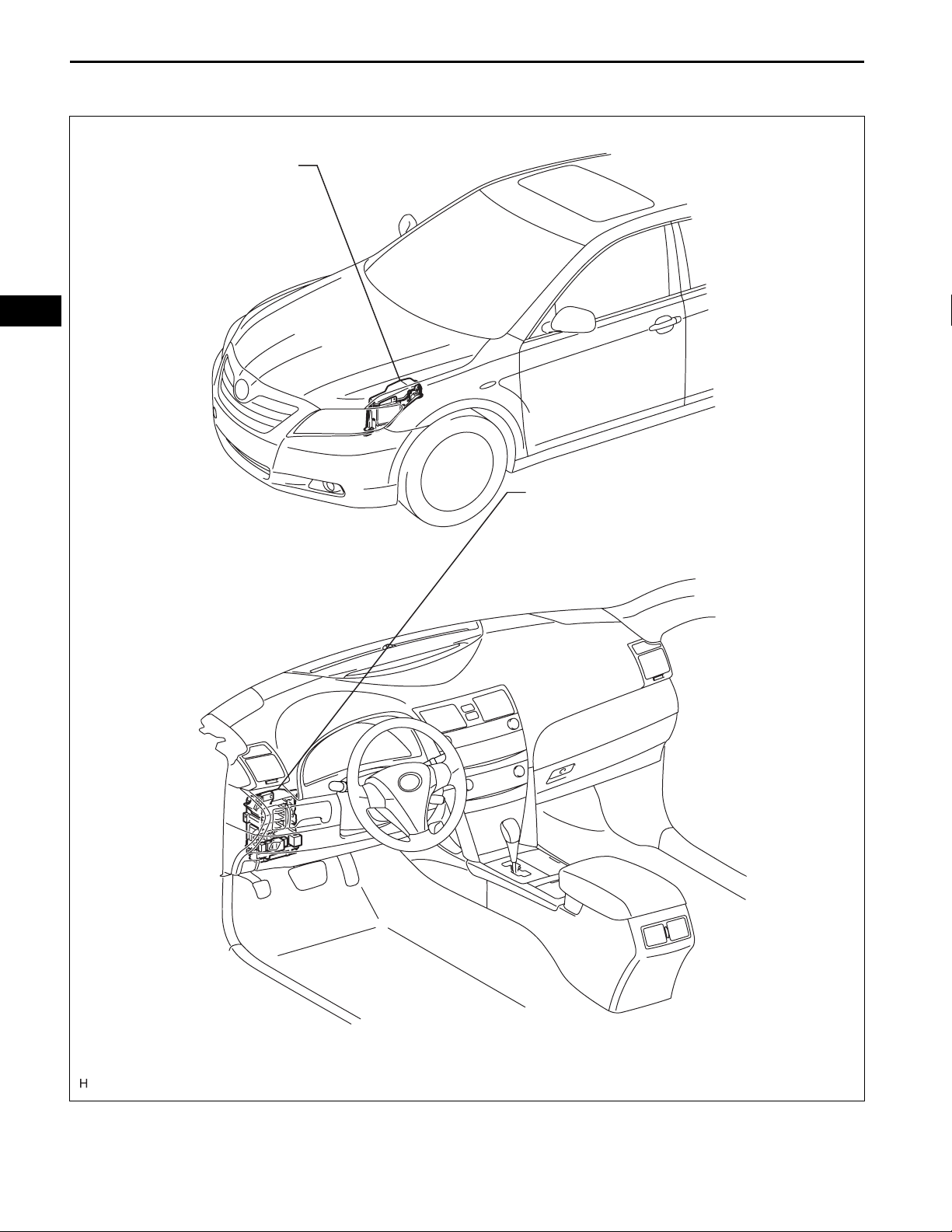
PARTS LOCATION
ENGINE ROOM J/B AND R/B
- ALT FUSE
SEAT – FRONT POWER SEAT CONTROL SYSTEM
MAIN BODY ECU
(INSTRUMENT PANEL J/B)
- P/SEAT FUSE
B126234E01
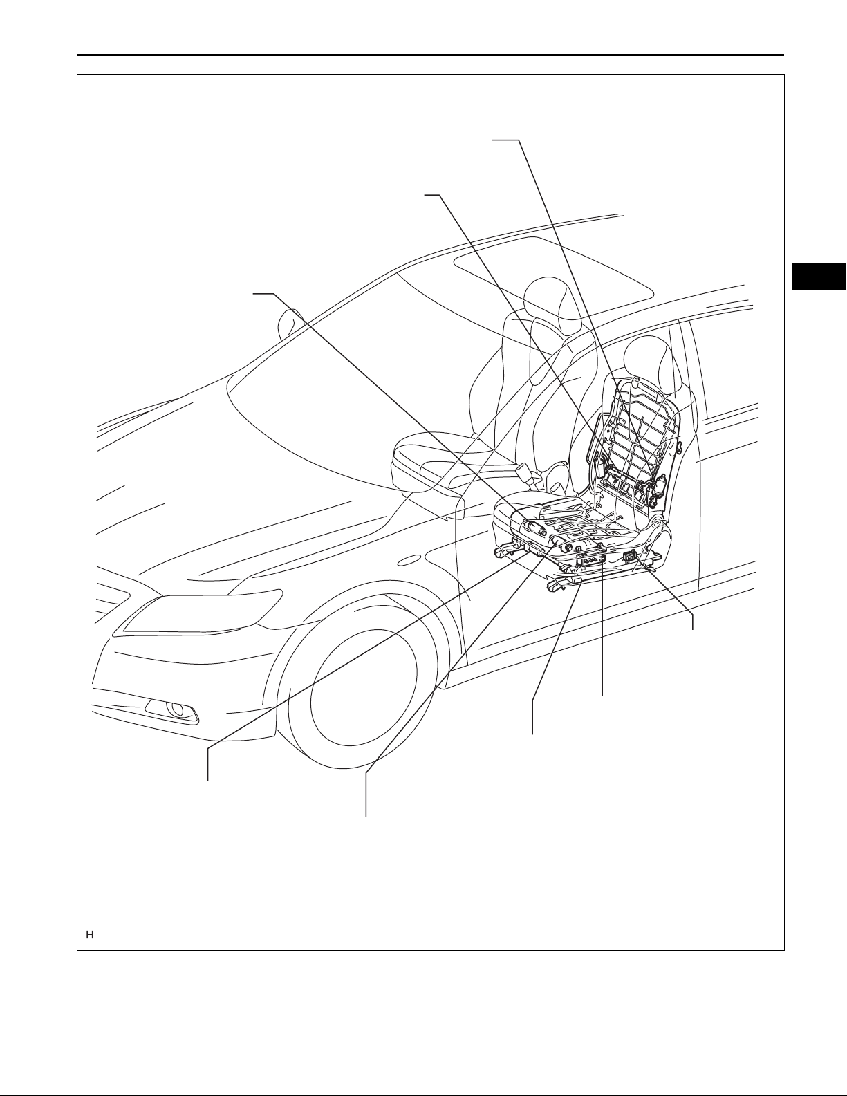
SEAT – FRONT POWER SEAT CONTROL SYSTEM
(RECLINING MOTOR)
LUMBAR SUPPORT ADJUSTER ASSEMBLY
SE–3
(LIFTER MOTOR)
SE
FRONT POWER SEAT
LUMBAR SWITCH
(SLIDE MOTOR)
(FRONT VERTICAL MOTOR)
POWER SEAT SWITCH
FRONT SEAT FRAME WITH ADJUSTER
- RECLINING MOTOR
- SLIDE MOTOR
- LIFTER MOTOR
- FRONT VERTICAL MOTOR
B126235E01
SE
SE–4
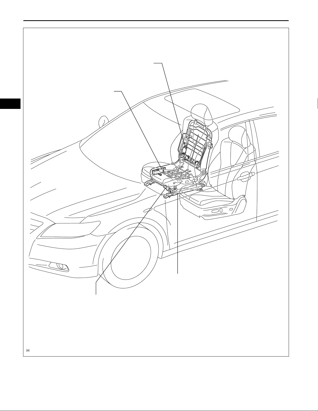
SEAT – FRONT POWER SEAT CONTROL SYSTEM
(RECLINING MOTOR)
POWER SEAT SWITCH
FRONT SEAT FRAME WITH ADJUSTER
- RECLINING MOTOR
- SLIDE MOTOR(SLIDE MOTOR)
B126236E01
Driver Side:
SEAT – FRONT POWER SEAT CONTROL SYSTEM
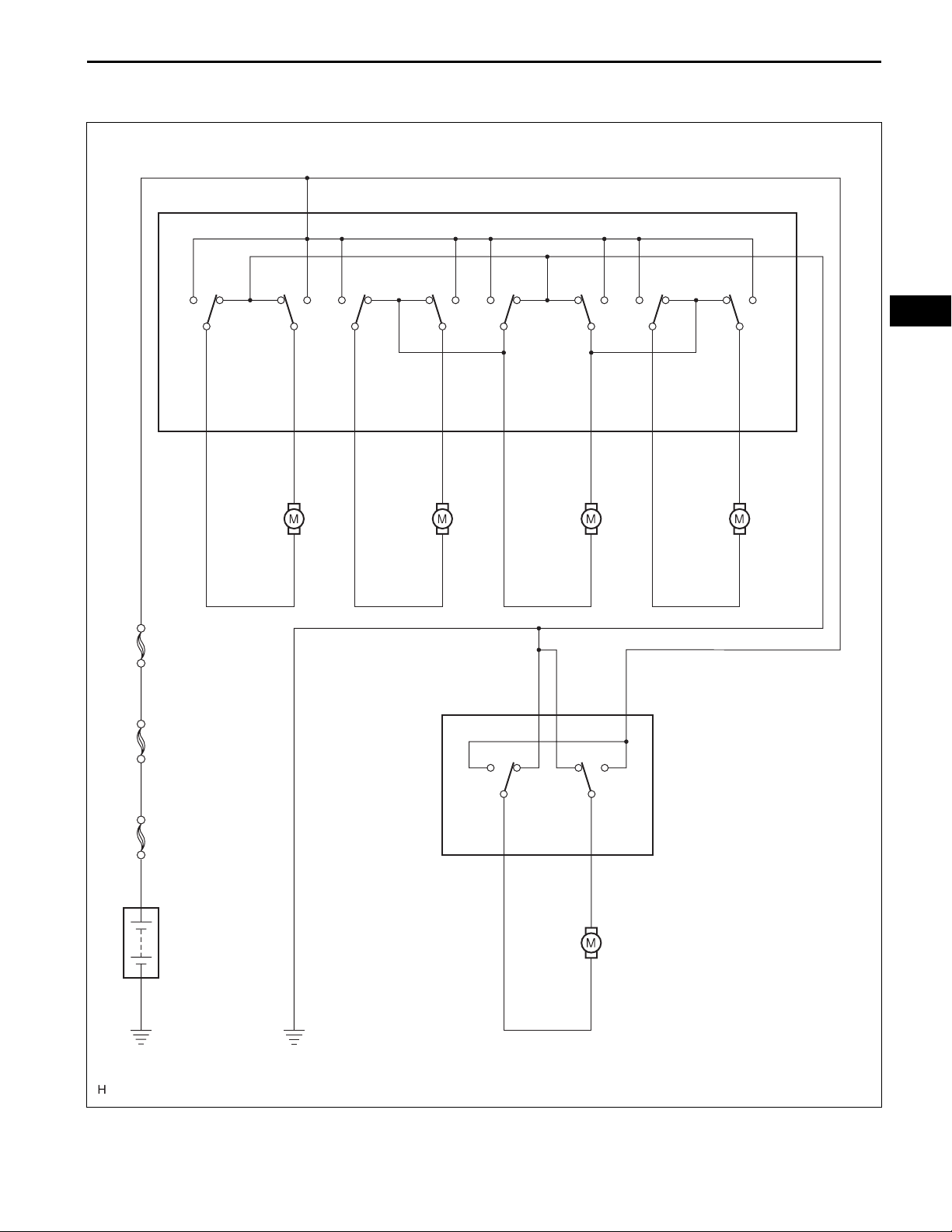
SYSTEM DIAGRAM
SE–5
Front Rear
Slide
SLDF
9
U1
Slide
Control
Motor
1
B
U7 Power Seat Switch LH
Up
Down Front Rear
Up
Down
4
E
SE
Front
Vertical
FDWNFUPSLDR
6
10
U2
Front
2
1
Vertical
Control
Motor
53
2
1
Reclining
RCLF
U3
Reclining
Control
Motor
Rear
Vertical
LDWNLUPRCLR
2
7
U4
Lifter
1
2
Control
Motor
8
1
2
P/SEAT
ALT
FL MAIN
Battery
2
5
R1 E
Rear
14
U5
Lumbar
Support
Motor
3
B
Front
HR
1
2
U8
Front Power Seat
Lumbar Switch
B127144E09

SE–6
Front Passenger Side:
SEAT – FRONT POWER SEAT CONTROL SYSTEM
T8
Power Seat Switch RH
1
B
E4
Front Rear Front Rear
SE
P/SEAT
ALT
Slide Reclining
SLDF SLFR RCLF RCLR
9632
T1
Slide Control
Motor
1
2
T9
Reclining
Control Motor
1
2
FL MAIN
Battery
B126237E01
SEAT – FRONT POWER SEAT CONTROL SYSTEM
SYSTEM DESCRIPTION
1. FRONT POWER SEAT CONTROL SYSTEM
DESCRIPTION
The driver seat and front passenger seat are equipped
with slide, reclining, lifter, front vertical, and lumbar
support adjustment functions.
2. FUNCTION OF MAIN COMPONENTS
The following functions are available:
Components Function
Power seat motor assembly (slide motor)
Power seat motor assembly (reclining motor)
Power seat motor assembly (front vertical motor)
Power seat motor assembly (lifter motor)
Lumbar support adjuster motor
Front power seat lumbar switch Based on switches operated, the seat is adjusted accordingly.
Activated based on a signal from the power seat switch, a motor is
activated and slides the seat forward and rearward.
Activated based on a signal from the power seat switch, a motor is
activated and tilts and reclines the seat.
Activated based on a signal from the power seat switch and raises
and lowers the seat cushion front vertically.
Activated based on a signal from the power seat switch and raises
and lowers the seat vertically.
Activated based on a signal from the front power seat lumbar switch
and adjusts lumbar support.
SE–7
SE
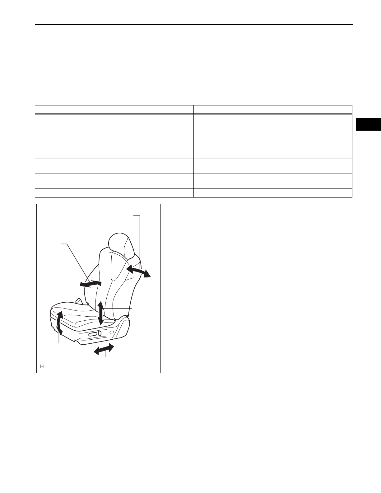
Lumbar
Support
Function
Front Vertical
Function
Reclining Function
Sliding Function
OPERATION CHECK
1. CHECK POWER SEAT FUNCTION
(a) Check the basic f unctions.
(1) Operate the power seat switches and check that
the following functions work:
• Sliding
• Reclining
• Lumbar support (Driver side only)
• Front vertical (Driver side only)
• Lifter (Driver side only)
Lifter
Function
B126238E01
SE
SE–8
SEAT – FRONT POWER SEAT CONTROL SYSTEM
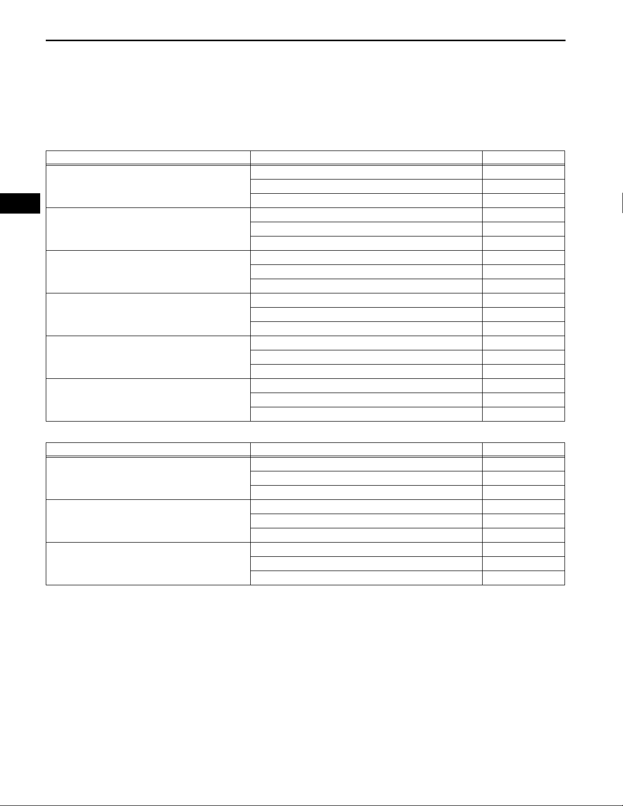
PROBLEM SYMPTOMS TABLE
HINT:
• Inspect the fuses and relays before confirming the
suspected areas in the table below.
• Inspect each suspected area in numerical order for the
corresponding symptom.
Front Power Seat Control System (Driver Side):
Symptom Suspected area See page
Power seat does not operate (slide, front vertical, lifter,
reclining).
Only slide operation function does not operate.
Only front vertical operation function does not operate.
Only lifter operation function does not operate.
Only reclining operation function does not operate.
Only lumbar support operation function does not
operate.
1. P/SEAT fuse -
2. Power seat switch LH SE-87
3. Wire harness or connector -
1. Power seat switch LH SE-87
2. Front seat frame with adjuster LH (slide motor) SE-90
3. Wire harness or connector -
1. Power seat switch LH SE-87
2. Front seat frame with adjuster LH (front vertical motor) SE-90
3. Wire harness or connector -
1. Power seat switch LH SE-87
2. Front seat frame with adjuster LH (lifter motor) SE-90
3. Wire harness or connector -
1. Power seat switch LH SE-87
2. Front seat frame with adjuster LH (reclining motor) SE-90
3. Wire harness or connector -
1. Front power seat lumbar switch LH SE-94
2. Lumbar support adjuster assembly LH SE-98
3. Wire harness or connector -
Front Power Seat Control System (Front Passenger Side):
Symptom Suspected area See page
1. P/SEAT fuse -
Power seat does not operate (slide and reclining).
Only slide operation function does not operate.
Only reclining operation function does not operate.
2. Power seat switch RH SE-89
3. Wire harness or connector -
1. Power seat switch RH SE-89
2. Front seat frame with adjuster RH (slide motor) SE-91
3. Wire harness or connector -
1. Power seat switch RH SE-89
2. Front seat frame with adjuster RH (reclining motor) SE-91
3. Wire harness or connector -

Expression
SEAT – SEAT HEATER SYSTEM
SE–9
SEAT HEATER SYSTEM
PRECAUTION
1. EXPRESSIONS OF IGNITION SWITCH
(a) The type of ignition switch used on this model differs
according to the specifications of the vehicle.
The expressions listed in the table below are used
in this section.
Switch Type Ignition Switch (position) Engine Switch (condition)
Ignition switch off LOCK Off
Ignition switch on (IG) ON On (IG)
Ignition switch on (ACC) ACC On (ACC)
Engine start START Start
SE
SE
SE–10
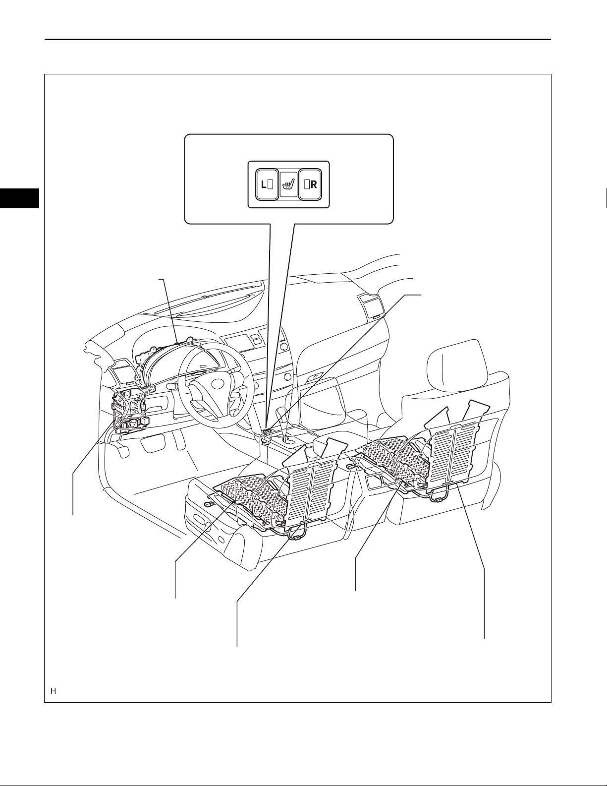
PARTS LOCATION
COMBINATION METER
SEAT – SEAT HEATER SYSTEM
SEAT HEATER SWITCH
SEAT HEATER SWITCH
MAIN BODY ECU
(INSTRUMENT PANEL J/B)
- S-HTR FUSE
- PANEL FUSE
FRONT SEAT CUSHION HEATER
(SEAT CUSHION HEATER LH)
FRONT SEATBACK HEATER
(SEATBACK HEATER LH)
FRONT SEAT CUSHION HEATER
(SEAT CUSHION HEATER RH)
FRONT SEATBACK HEATER
(SEATBACK HEATER RH)
B137070E01
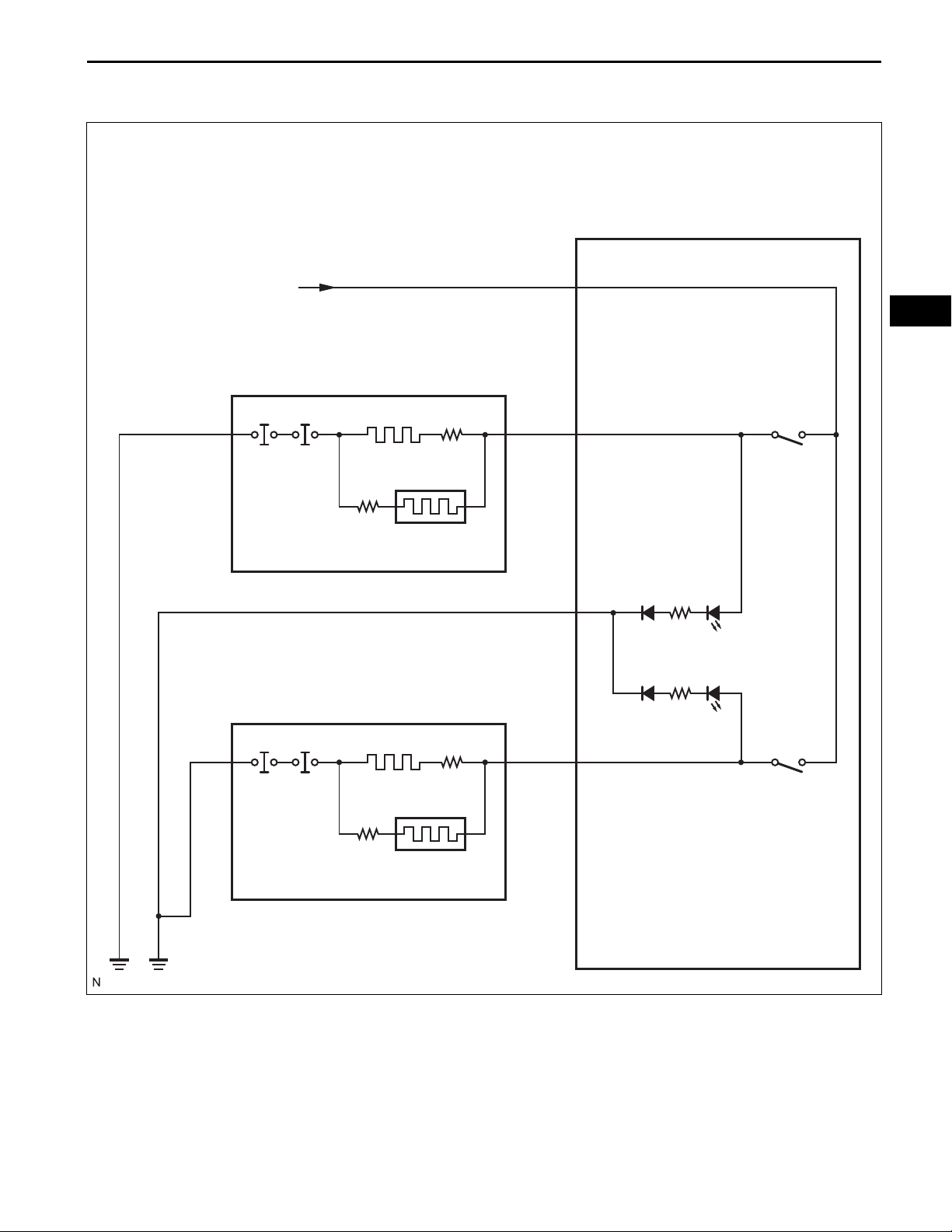
SEAT – SEAT HEATER SYSTEM
SYSTEM DIAGRAM
E55
Seat Heater Switch
SE–11
From S-HTR Fuse
T6
Seat Heater RH
U6
Seat Heater LH
Seat Cushion
Seat Back
IG
5
SE
RH
312
E
4
RH Side
Seat SW
Seat Cushion
Seat Back
12
LH
6
LH Side
Seat SW
B126243E01

SE
SE–12
SEAT – SEAT HEATER SYSTEM
SYSTEM DESCRIPTION
1. GENERAL DESCRIPTION
(a) By operating the seat heater switch, which is
located in the console box, the temperature can be
controlled within the range of 30 to 40°C (86 to
104°F).
(b) The seat heater switch indicator light provides seat
heater on/off status.
(c) The seat heaters of both seats are controlled by the
seat heater controls, which are located under the
respective seat.
SEAT – SEAT HEATER SYSTEM
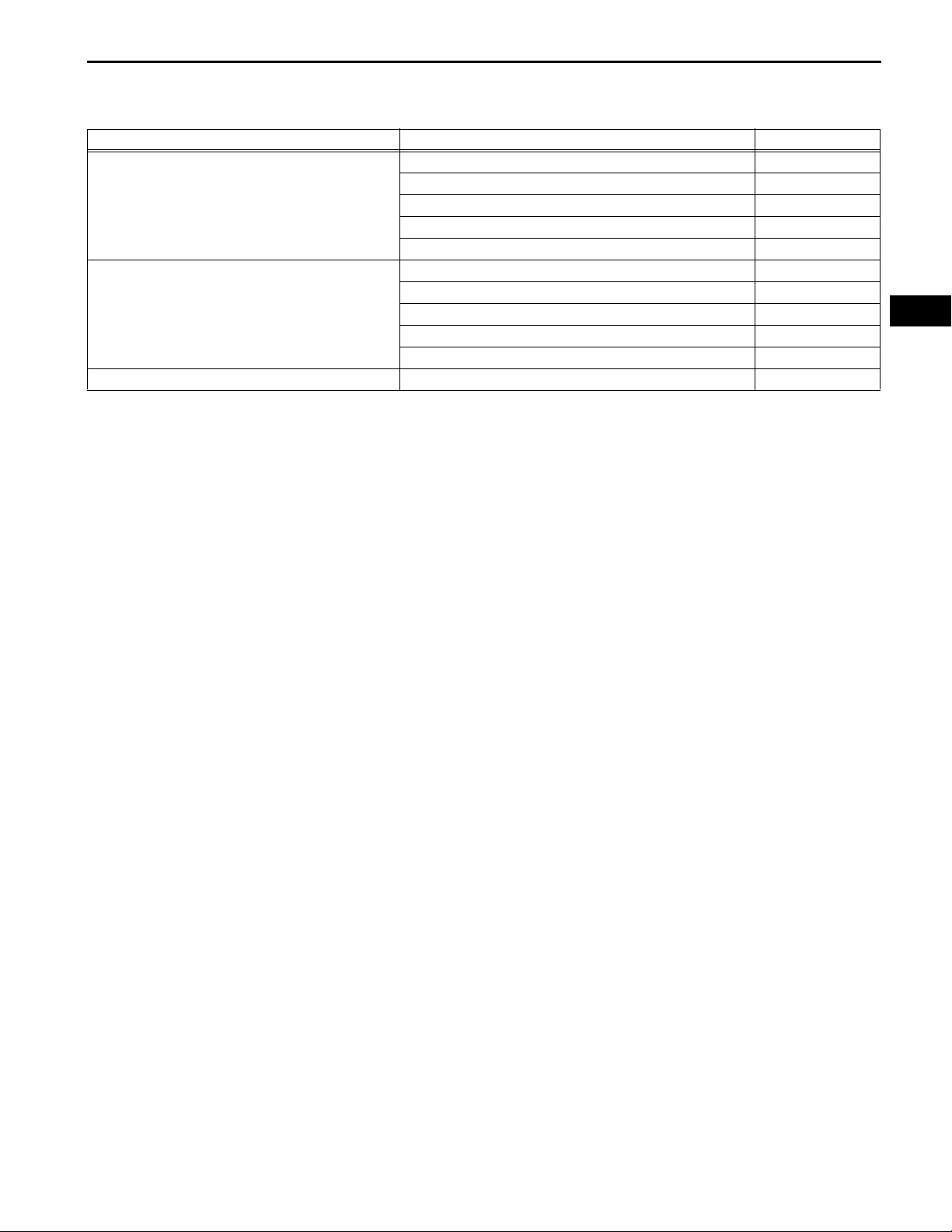
PROBLEM SYMPTOMS TABLE
SEAT HEATER SYSTEM:
Symptom Suspected area See page
1. S-HTR fuse -
2. Seat heater switch SE-101
Seat heater does not operate. (Front LH side)
Seat heater does not operate. (Front RH side)
Temperature of seat heater cannot be adjusted. Seat heater switch SE-101
3. Front seat cushion heater SE-106
4. Front seat back heater SE-111
5. Wire harness -
1. S-HTR fuse -
2. Seat heater switch SE-101
3. Front seat cushion heater SE-106
4. Front seat back heater SE-111
5. Wire harness -
SE–13
SE
SEAT – FRONT SEAT ASSEMBLY (for Manual Seat)
BODYSEAT
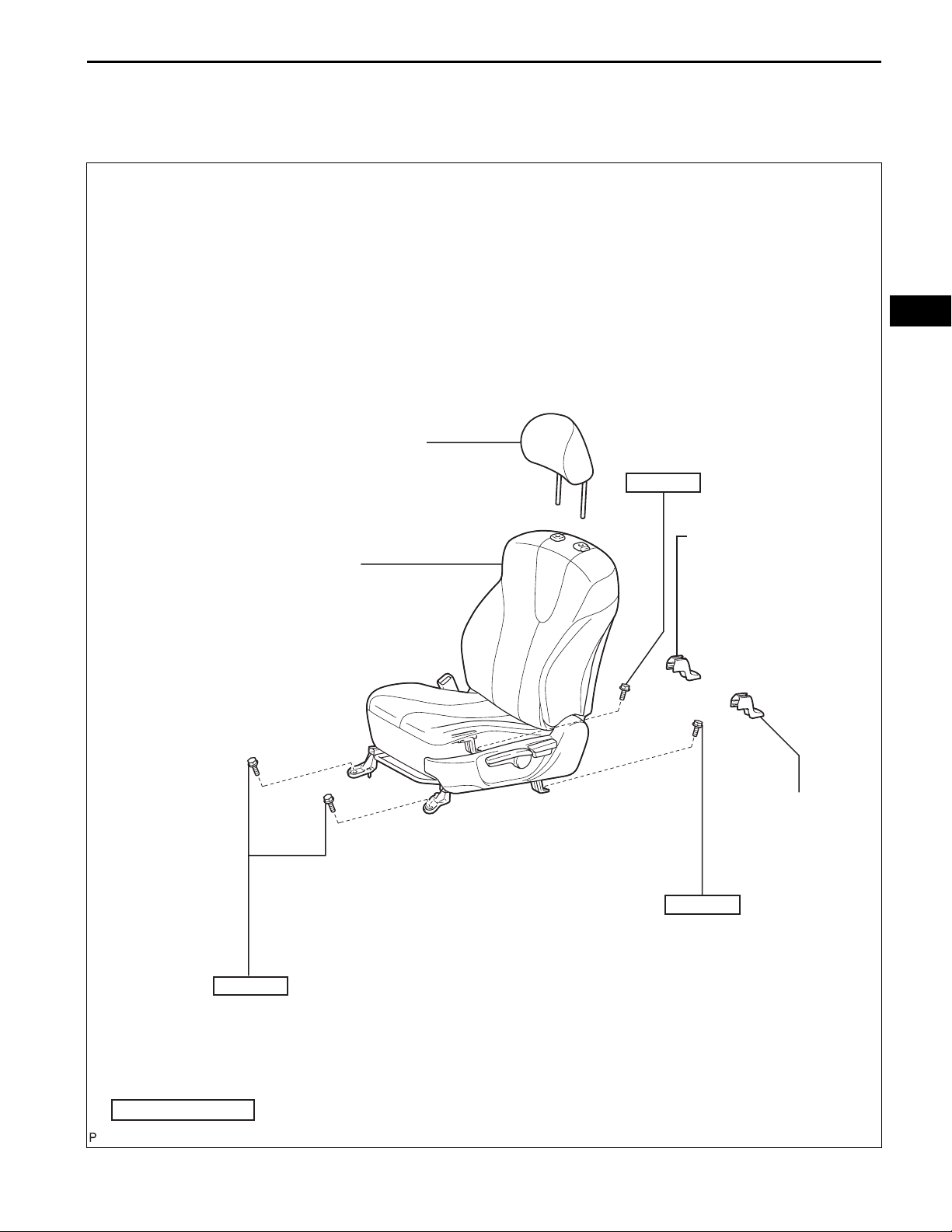
FRONT SEAT ASSEMBLY (for Manual Seat)
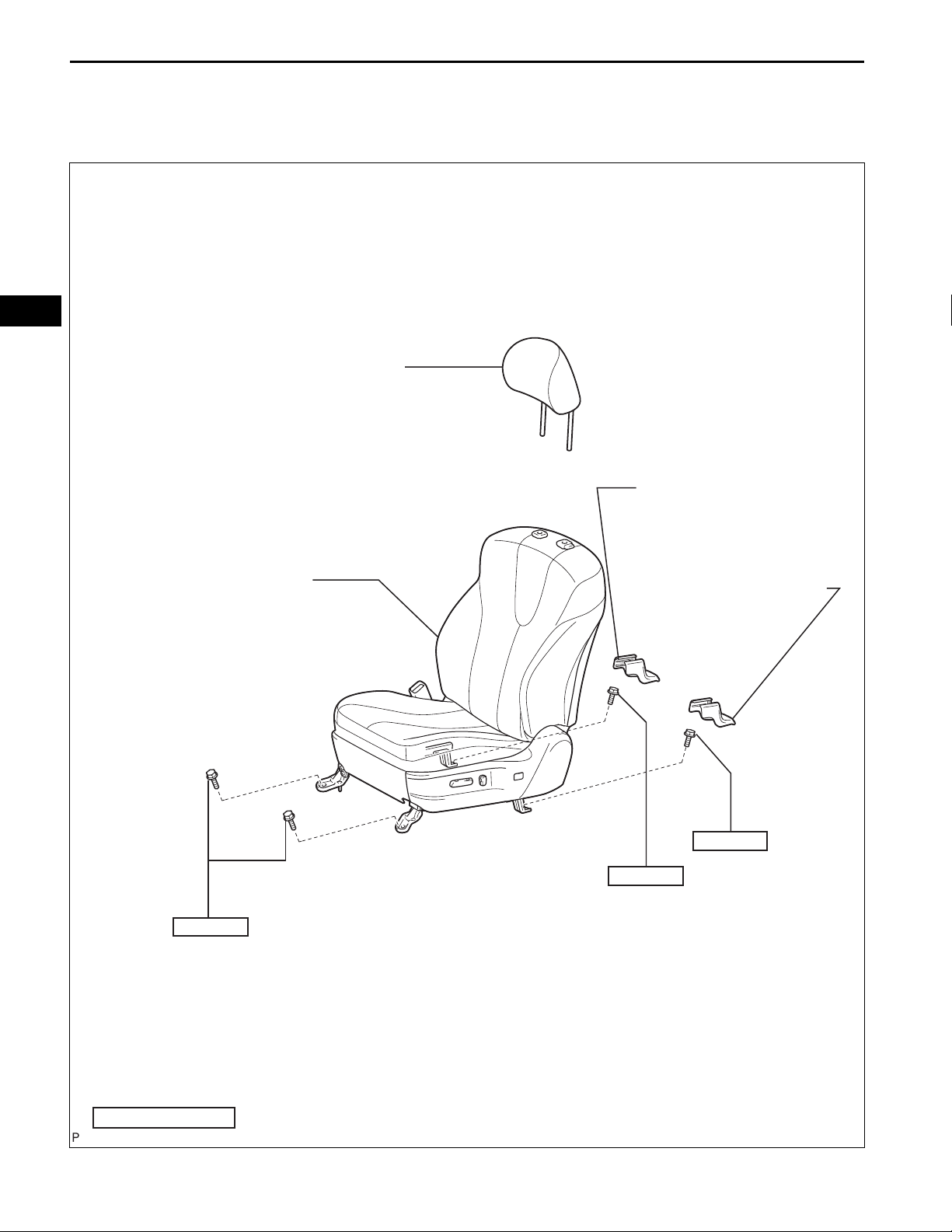
COMPONENTS
FRONT SEAT HEADREST ASSEMBLY
37 (377, 27)
SE–13
SE
FRONT SEAT ASSEMBLY
INNER SEAT TRACK
BRACKET COVER
SEAT TRACK
COVER
37 (377, 27)
37 (377, 27)
N*m (kgf*cm, ft.*lbf)
: Specified torque
B139116E01
SE–14
SEAT – FRONT SEAT ASSEMBLY (for Manual Seat)
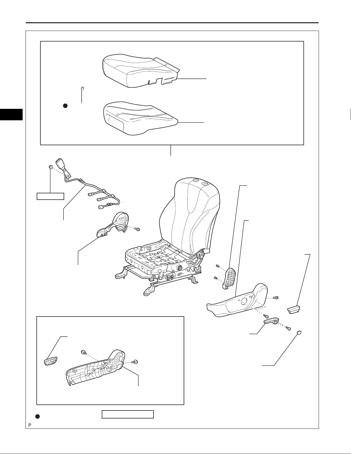
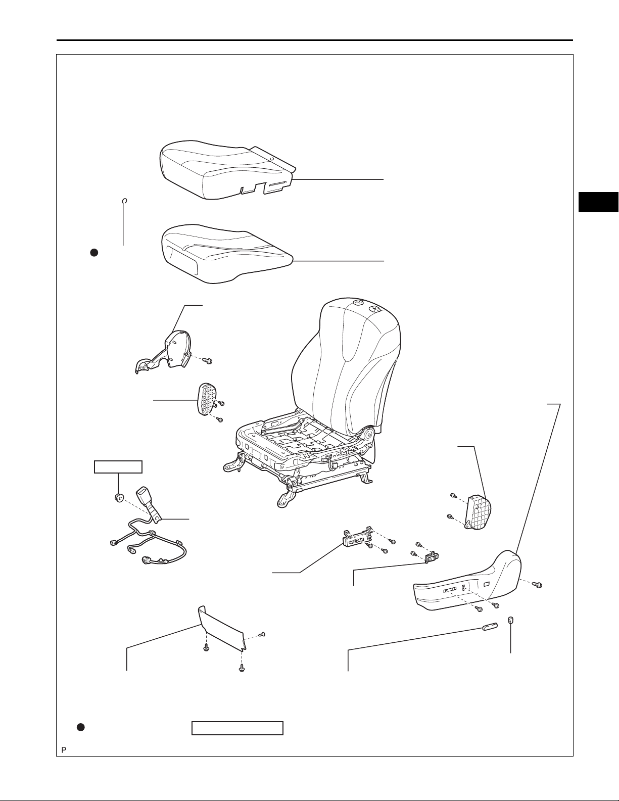
SEPARATE TYPE FRONT SEAT
CUSHION COVER
HOG RING
SE
42 (428, 31)
FRONT SEAT INNER
BELT ASSEMBLY
FRONT INNER SEAT
CUSHION SHIELD
SEPARATE TYPE FRONT SEAT
CUSHION PAD
FRONT SEAT CUSHION COVER WITH PAD
LOWER SEAT
TRACK SPACER
FRONT SEAT
CUSHION SHIELD
RECLINING ADJUSTER
RELEASE HANDLE
for Front Passenger Seat:
RECLINING ADJUSTER RELEASE HANDLE
Non-reusable part
N*m (kgf*cm, ft.*lbf)
VERTICAL ADJUSTING
HANDLE NO. 2
VERTICAL ADJUSTER
COVER LH
FRONT SEAT
CUSHION SHIELD
: Specified torque
B139117E01
HOG RING
SEAT – FRONT SEAT ASSEMBLY (for Manual Seat)
FRONT SEAT HEADREST
SUPPORT
FRONT SEAT BACK BOARD
5.5 (56, 49 in.*lbf)
SUB-ASSEMBLY
SE–15
SE
FRONT SEPARATE TYPE
SEAT BACK COVER
FRONT SEAT BACK COVER WITH PAD
RECLINING ADJUSTER
INSIDE COVER RH
RECLINING ADJUSTER
INSIDE COVER RH
SEAT SLIDE POSITION SENSOR PROTECTOR
FRONT SEPARATE TYPE
SEAT BACK PAD
FRONT LOWER SEAT
CUSHION SHIELD RH
FRONT LOWER SEAT
CUSHION SHIELD LH
RECLINING ADJUSTER
INSIDE COVER LH
8.0 (82, 71 in.*lbf)
SEAT POSITION SENSOR
Non-reusable part
N*m (kgf*cm, ft.*lbf)
RECLINING ADJUSTER
INSIDE COVER LH
: Specified torque
B139118E01
SE
SE–16
SEAT – FRONT SEAT ASSEMBLY (for Manual Seat)
REMOVAL
1. DISCONNECT CABLE FROM NEGATIVE BATTERY
TERMINAL
CAUTION:
Wait for 90 seconds after disconnecting the cable to
prevent the airbag from deploying (See page RS-1).
2. REMOVE FRONT SEAT HEADREST ASSEMBLY
3. REMOVE SEAT TRACK COVER
(a) Move the front seat assembly fully forward by
operating the slide handle.
(b) Using a screwdriver, disengage the 4 claws and
remove the seat track cover.
HINT:
Tape the screwdriver tip before use.
B139099
B139100
4. REMOVE INNER SEAT TRACK BRACKET COVER
(a) Using a screwdriver, disengage the 4 claws and
remove the inner seat track bracket cover.
HINT:
Tape the screwdriver tip before use.
5. REMOVE FRONT SEAT ASSEMBLY
(a) Move the front seat assembly to the rearmost
position by operating the slide handle.
SEAT – FRONT SEAT ASSEMBLY (for Manual Seat)
(b) Remove the 2 bolts on the front seat track bracket.
(c) Move the front seat assembly fully forward by
operating the slide handle.
B139101
SE–17
B139102
(d) Remove the 2 bolts on the rear seat track bracket.
(e) Move the front seat assembly to the center position
and adjust the seatback to the vertical position by
operating the slide and reclining adjuster release
handle.
(f) Disconnect the connectors and clamp.
(g) Remove the front seat assembly.
SE
SE–26
SEAT – FRONT SEAT ASSEMBLY (for Manual Seat)
INSTALLATION
1. INSTALL FRONT SEAT ASSEMBLY
(a) Place the front seat assembly in the vehicle and
align the adjuster pin with the hole on the vehicle
side.
(b) Connect the connector and clamp.
(c) Move the front seat assembly to the rearmost
position by operating the slide handle.
NOTICE:
Check that the seat is locked.
SE
B139101
B139102
(d) Temporarily install the front seat track bracket with
the 2 bolts.
(e) Move the front seat assembly fully forward by
operating the slide handle.
NOTICE:
Check that the seat is locked.
(f) Temporarily install the rear seat track bracket with
the 2 bolts.
(g) Move the front seat assembly to the rearmost
position by operating the slide handle.
NOTICE:
Check that the seat is locked.
(h) Fully tighten the 2 bolts on the front seat track
bracket in the order of the inner side bolt and then
the outer side bolt.
Torque: 37 N*m (377 kgf*cm, 27 ft.*lbf)
(i) Move the front seat assembly fully forward by
operating the slide handle.
NOTICE:
Check that the seat is locked.
(j) Fully tighten the 2 bolts on the rear seat track
bracket in the order of the inner side bolt and then
the outer side bolt.
Torque: 37 N*m (377 kgf*cm, 27 ft.*lbf)
Claw A
SEAT – FRONT SEAT ASSEMBLY (for Manual Seat)
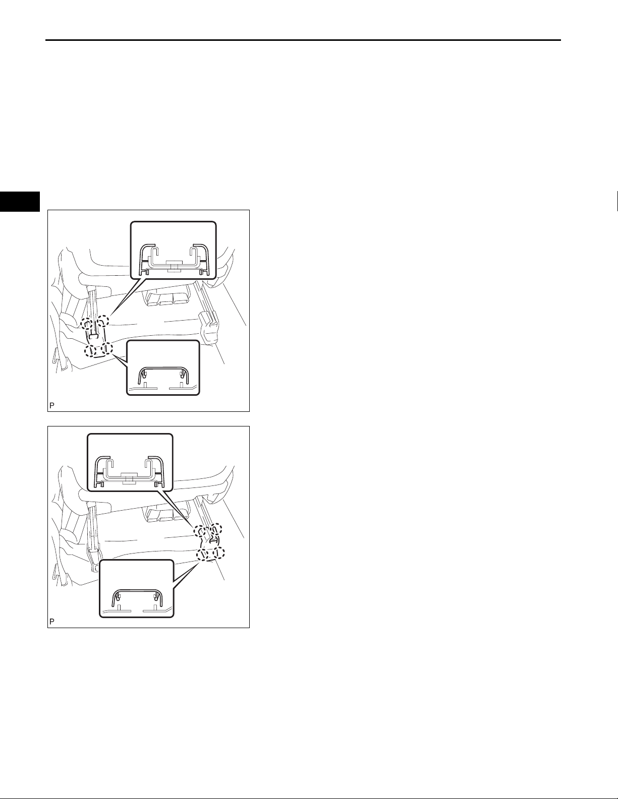
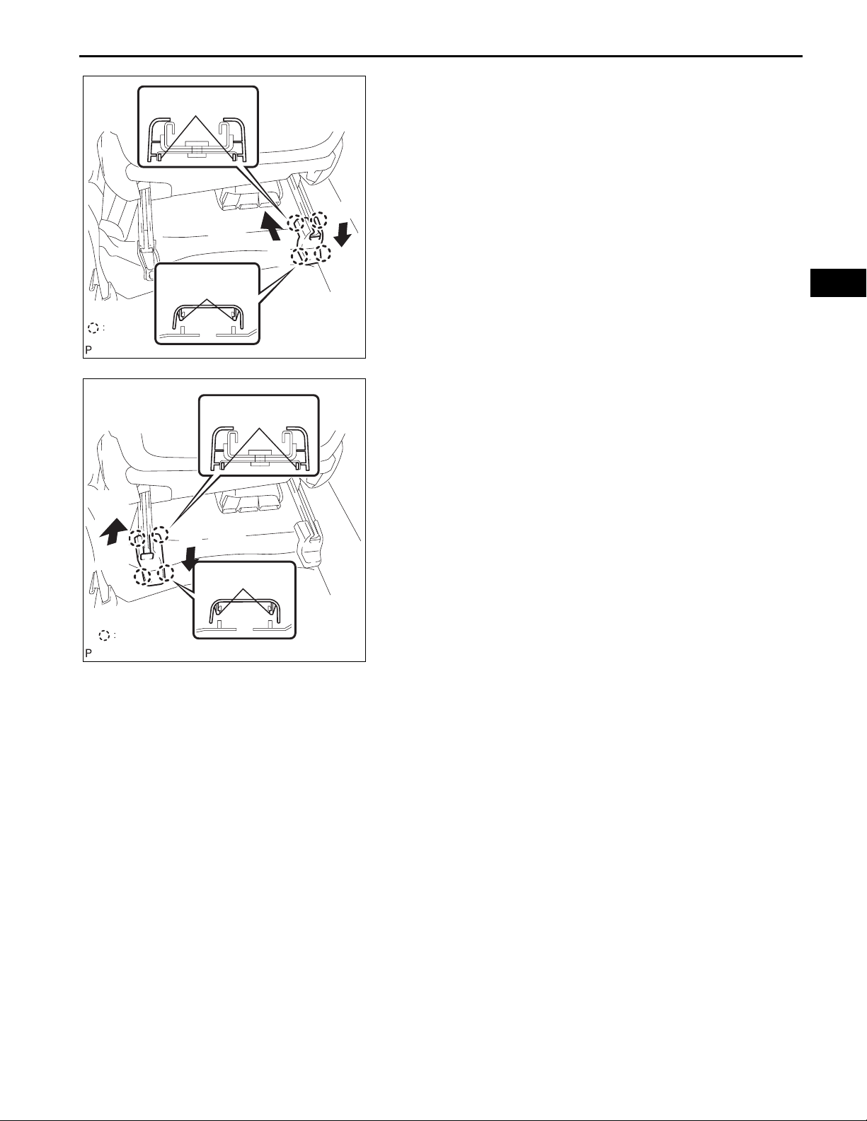
2. INSTALL INNER SEAT TRACK BRACKET COVER
(a) Slide the inner seat track bracket cover along the
seat rail toward the front of the vehicle. Engage claw
A to the seat rail.
(b) Push the seat track bracket cover inner to engage
claw B.
(2)
(1)
SE–27
Claw
(1)
Claw
Claw B
(2)
Claw A
Claw B
B139100E01
B139099E01
SE
3. INSTALL SEAT TRACK COVER
(a) Slide the seat track cover along the seat rail toward
the front of the vehicle. Engage claw A to the seat
rail.
(b) Push the seat track cover to engage claw B.
4. INSTALL FRONT SEAT HEADREST ASSEMBLY
5. CONNECT CABLE TO NEGATIVE BATTERY
TERMINAL
6. INSPECT SLIDE ADJUSTER LOCK
7. PERFORM ZERO POINT CALIBRATION AND
SENSITIVITY CHECK (for Front Passenger Seat)
(See page RS-242)
8. INSPECT SRS WARNING LIGHT
Check the SRS warning light (See page RS-32).
SE
SE–18
SEAT – FRONT SEAT ASSEMBLY (for Manual Seat)
DISASSEMBLY
NOTICE:
Wear protective gloves. Sharp areas on the seat frame
and adjuster may injure your hands.
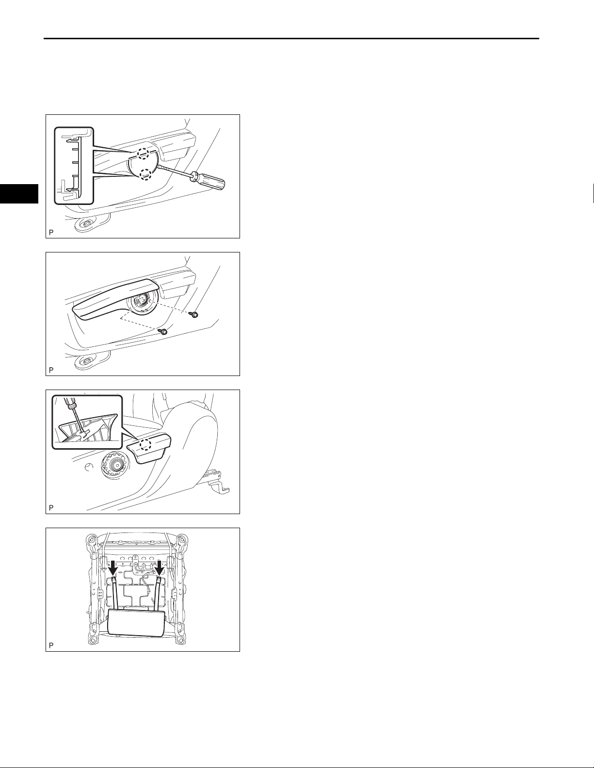
1. REMOVE VERTICAL ADJUSTER COVER LH (for
Driver Seat)
(a) Using a screwdriver, disengage the 2 claws and
remove the vertical adjuster cover LH.
HINT:
Tape the screwdriver tip before use.
B139103
2. REMOVE VERTICAL ADJUSTING HANDLE NO. 2 (for
Driver Seat)
(a) Remove the 2 screws and vertical adjusting handle.
B139104
B139105
B139108
3. REMOVE RECLINING ADJUSTER RELEASE
HANDLE
(a) Lift the reclining adjuster release handle.
(b) Using a screwdriver, disengage the claw and
remove the reclining adjuster release handle.
HINT:
Tape the screwdriver tip before use.
4. REMOVE FRONT SEAT CUSHION SHIELD
(a) Disengage the 2 hooks.

SEAT – FRONT SEAT ASSEMBLY (for Manual Seat)
(b) Remove the 3 screws.
(c) Disengage the 2 claws and remove the front seat
cushion shield.
B139106
SE–19
B139122
B139107
5. REMOVE LOWER SEAT TRACK SPACER
(a) Remove the 2 screws and lower seat track spacer.
6. REMOVE FRONT SEAT INNER BELT ASSEMBLY
(See page SB-15)
7. REMOVE FRONT INNER SEAT CUSHION SHIELD
(a) Remove the screw.
(b) Disengage the claw and clip, and then remove the
front inner seat cushion shield.
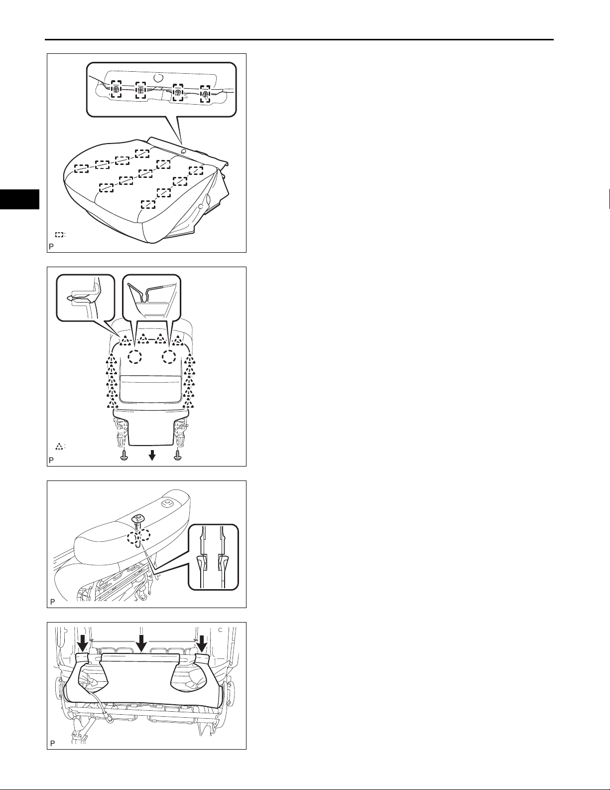
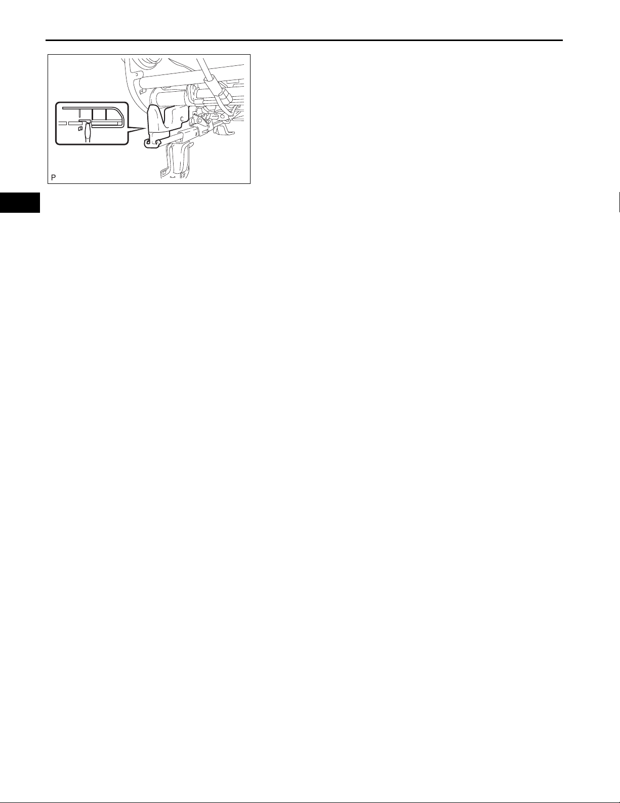
8. REMOVE FRONT SEAT CUSHION COVER WITH PAD
(a) Disengage the clamp.
(b) Disengage the hooks and remove the front seat
cushion cover with pad.
SE
Clamp
B139123E01
SE
SE–20
SEAT – FRONT SEAT ASSEMBLY (for Manual Seat)
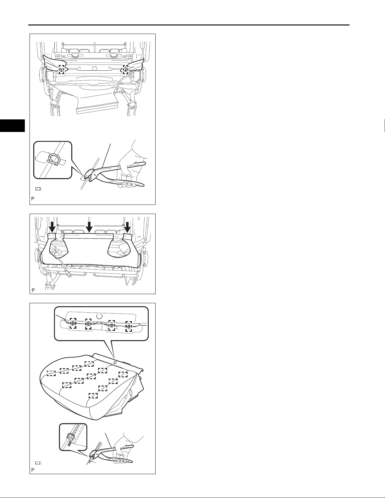
9. REMOVE SEPARATE TYPE FRONT SEAT CUSHION
COVER
(a) Remove the 16 hog rings and separate type front
seat cushion cover.
Hog Ring
Clamp
B139121E01
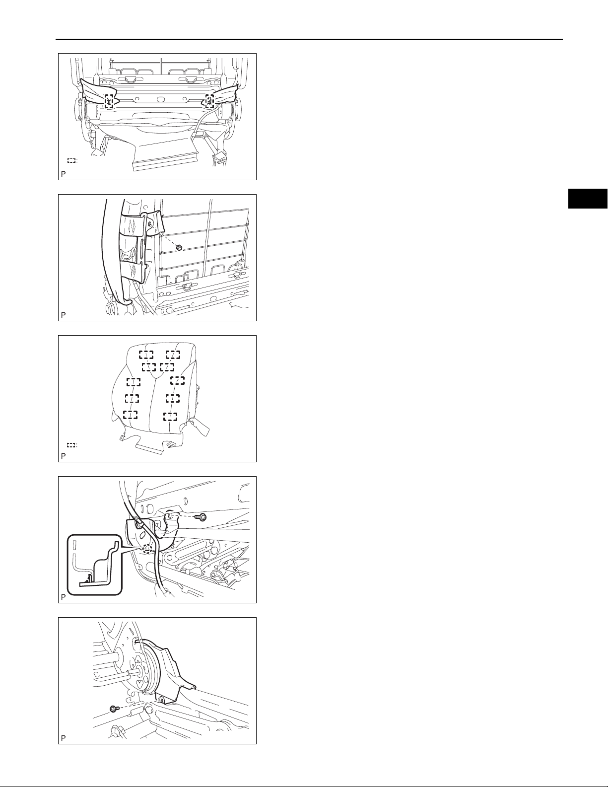
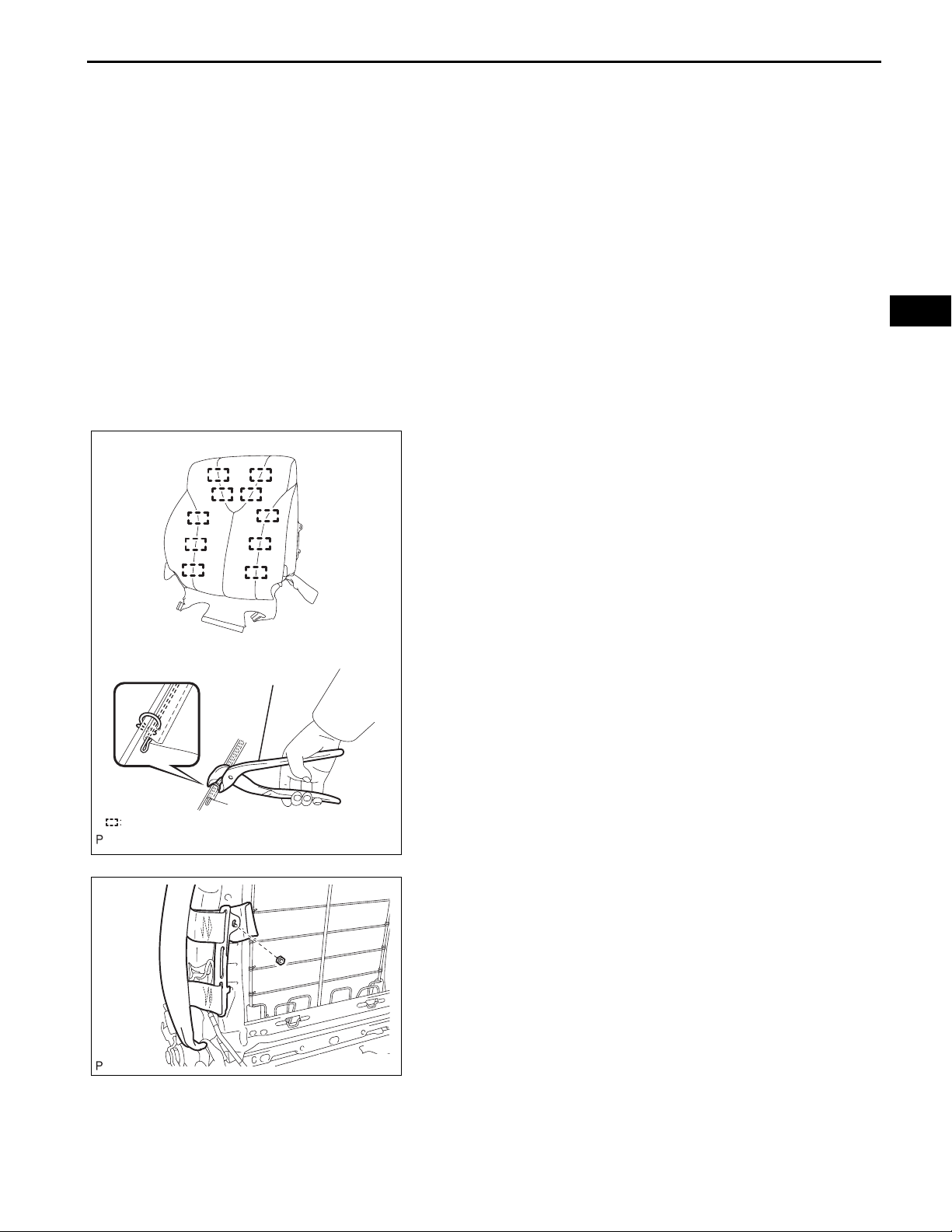
10. REMOVE FRONT SEAT BACK BOARD SUBASSEMBLY
(a) Remove the 2 screws.
(b) Disconnect the 14 clamps and front separate type
seat back cover.
(c) Pull the seat back board in the direction indicated by
the arrow in the illustration to detach the 2 claws.
Then, remove the seat back board.
B134682E01
11. REMOVE FRONT SEAT HEADREST SUPPORT
(a) Detach the 2 claws and remove the headrest
support.
B134683
B139109
12. REMOVE FRONT SEAT HEADREST SUPPORT
13. REMOVE FRONT SEAT BACK COVER WITH PAD
(a) Disengage the 3 hooks.
Hog Ring
SEAT – FRONT SEAT ASSEMBLY (for Manual Seat)
(b) Remove the 2 hog rings.
B139110E01
SE–21
Hog Ring
B139111
B139112E01
(c) Remove the nut and separate the 2 brackets.
(d) Remove the front seat back cover with pad.
14. REMOVE FRONT SEPARATE TYPE SEAT BACK
COVER
(a) Remove the 10 hog rings and front separate type
seat back cover.
15. REMOVE RECLINING ADJUSTER INSIDE COVER LH
(a) Disconnect the clamp.
(b) Remove the screw.
(c) Disengage the claw and remove the reclining
adjuster inside cover LH.
SE
B139113
B139114
16. REMOVE RECLINING ADJUSTER INSIDE COVER RH
HINT:
Use the same procedures for the RH side and LH side.
17. REMOVE RECLINING ADJUSTER INSIDE COVER LH
(a) Remove the screw and reclining adjuster inside
cover LH.
18. REMOVE RECLINING ADJUSTER INSIDE COVER RH
HINT:
Use the same procedures for the RH side and LH side.
SE–22
SEAT – FRONT SEAT ASSEMBLY (for Manual Seat)
19. REMOVE FRONT LOWER SEAT CUSHION SHIELD
LH
(a) Using a screwdriver, disengage the claw and
remove the front lower seat cushion shield LH.
20. REMOVE FRONT LOWER SEAT CUSHION SHIELD
RH
HINT:
Use the same procedures for the RH side and LH side.
SE
B139115
21. REMOVE SEAT POSITION SENSOR (for Driver Seat)
(See page RS-461)
SEAT – FRONT SEAT ASSEMBLY (for Manual Seat)
REASSEMBLY
NOTICE:
Wear protective gloves. Sharp areas on the seat frame
and adjuster may injure your hands.
1. INSTALL SEAT POSITION SENSOR (for Driver Side)
(See page RS-464)
2. INST ALL FRONT LOWER SEAT CUSHION SHIELD LH
3. INSTALL FRONT LOWER SEAT CUSHION SHIELD
RH
SE–23
Hog Ring Pliers
4. INSTALL RECLINING ADJUSTER INSIDE COVER LH
5. INSTALL RECLINING ADJUSTER INSIDE COVER RH
6. INSTALL RECLINING ADJUSTER INSIDE COVER LH
7. INSTALL RECLINING ADJUSTER INSIDE COVER RH
8. INSTALL FRONT SEPARATE TYPE SEAT BACK
COVER
(a) Using hog ring pliers, install the front separate type
seat back cover to the front separate type seat back
pad with 10 new hog rings.
NOTICE:
• Be careful not to damage the cover.
• When installing the hog rings, take care to
minimize wrinkles as much as possible.
SE
Hog Ring
B140574E01
B139111
9. INSTALL FRONT SEAT BACK COVER WITH PAD
(a) Fully cover the airbag with the 2 seat back cover
brackets and tighten the nut.
Torque: 5.5 N*m (56 kgf*cm, 49 in.*lbf)
NOTICE:
• For vehicles with side airbags, the seat back
cover must be securely installed. Otherwise,
the side airbags may not deploy properly.
• Make sure that the strap is not twisted after
installing the bracket.
• Install the bracket securely.
SE–24
SEAT – FRONT SEAT ASSEMBLY (for Manual Seat)
(b) Using hog ring pliers, install the seat back cover
(with pad) to the seat frame with 2 new hog rings,
and attach the hooks.
SE
Hog Ring Pliers
Hog Ring
B140573E01
(c) Engage the 3 hooks.
10. INSTALL FRONT SEAT HEADREST SUPPORT
11. INSTALL FRONT SEAT HEADREST SUPPORT
12. INSTALL FRONT SEAT BACK BOARD SUBASSEMBLY
B139109
13. INSTALL SEPARATE TYPE FRONT SEAT CUSHION
COVER
(a) Using hog ring pliers, install the separate type front
seat cushion cover to the seat back pad with 16 new
hog rings.
NOTICE:
• Be careful not to damage the cover.
• When installing the hog rings, take care to
minimize wrinkles as much as possible.
Hog Ring
Hog Ring Pliers
14. INSTALL FRONT SEAT CUSHION COVER WITH PAD
15. INSTALL FRONT INNER SEAT CUSHION SHIELD
16. INST ALL FRONT SEA T INNER BELT ASSEMBLY (See
page SB-16)
17. INSTALL LOWER SEAT TRACK SPACER
18. INSTALL FRONT SEAT CUSHION SHIELD (for Driver
Seat)
19. INSTALL RECLINING ADJUSTER RELEASE HANDLE
B140572E01

SEAT – FRONT SEAT ASSEMBLY (for Manual Seat)
20. INSTALL VERTICAL ADJUSTING HANDLE NO. 2 (for
Driver Seat)
21. INSTALL VERTICAL ADJUSTER COVER LH (for
Driver Seat)
SE–25
SE
SE
SE–26
BODYSEAT
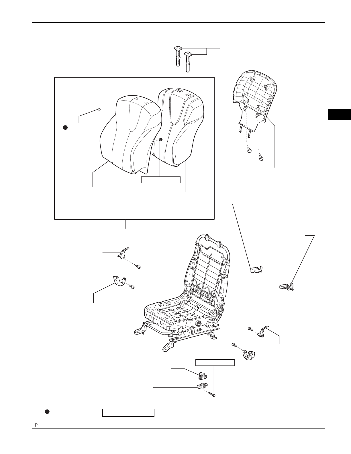
SEAT – FRONT SEAT ASSEMBLY (for Power Seat)
FRONT SEAT ASSEMBLY (for Power Seat)
COMPONENTS
FRONT SEAT HEADREST ASSEMBLY
INNER SEAT TRACK
BRACKET COVER
FRONT SEAT ASSEMBLY
37 (377, 27)
SEAT TRACK COVER
37 (377, 27)
37 (377, 27)
N*m (kgf*cm, ft.*lbf)
: Specified torque
B134694E01
SEAT – FRONT SEAT ASSEMBLY (for Power Seat)
FRONT SEPARATE TYPE
SEAT CUSHION COVER
SE–27
SE
HOG RING
LOWER SEAT
TRACK SPACER
42 (428, 31)
FRONT SEPARATE TYPE
SEAT CUSHION PAD
FRONT INNER SEAT
CUSHION SHIELD
FRONT SEAT CUSHION SHIELD
LOWER SEAT
TRACK SPACER
FRONT SEAT INNER
BELT ASSEMBLY
FRONT INNER NO. 1
SEAT CUSHION SHIELD
Non-reusable part
FRONT POWER
SEAT SWITCH
N*m (kgf*cm, ft.*lbf)
FRONT LUMBAR
POWER SEAT SWITCH
SLIDE AND VERTICAL
POWER SEAT SWITCH KNOB
: Specified torque
RECLINING POWER
SEAT SWITCH KNOB
B134695E01

SE
SE–28
SEAT – FRONT SEAT ASSEMBLY (for Power Seat)
FRONT SEAT HEADREST SUPPORT
HOG RING
FRONT SEPARATE TYPE
SEAT BACK COVER
5.5 (56, 49 in.*lbf)
FRONT SEAT BACK BOARD
SUB-ASSEMBLY
for Sport Seat Type :
Non-reusable part
N*m (kgf*cm, ft.*lbf)
: Specified torque
B134696E01

SEAT – FRONT SEAT ASSEMBLY (for Power Seat)
SEAT RECLINING ADJUSTER
INSIDE COVER RH
RECLINING ADJUSTER
INSIDE COVER RH
FRONT LOWER SEAT
CUSHION SHIELD
SEAT SLIDE POSITION
SENSOR PROTECTOR
SE–29
LUMBAR SUPPORT ADJUSTER
ASSEMBLY
SE
RECLINING ADJUSTER
INSIDE COVER LH
SEAT RECLINING
ADJUSTER INSIDE
COVER LH
8.0 (82, 71 in.*lbf)
SEAT POSITION SENSOR
FRONT LOWER SEAT
CUSHION SHIELD LH
for Sport Seat Type:
FRONT SEAT WIRE
N*m (kgf*cm, ft.*lbf)
: Specified torque
B144024E01

SE
SE–30
SEAT – FRONT SEAT ASSEMBLY (for Power Seat)
REMOVAL
1. REMOVE FRONT SEAT HEADREST ASSEMBLY
2. REMOVE SEAT TRACK COVER
(a) Operate the power seat switch knob and move the
seat to the position farthest forward.
(b) Using a screwdriver, det ach the 4 claws and remove
the seat track cover.
HINT:
Tape the screwdriver tip before use.
B139099
B139100
3. REMOVE INNER SEAT TRACK BRACKET COVER
(a) Using a screwdriver, det ach the 4 claws and remove
the inner seat track bracket cover.
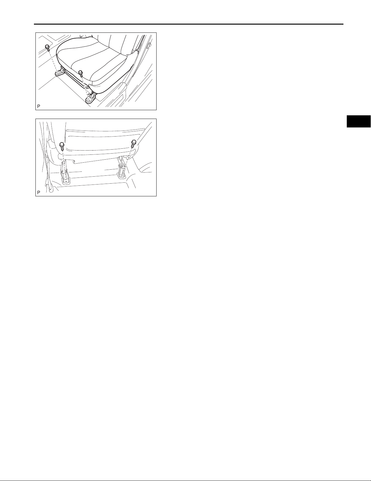
4. REMOVE FRONT SEAT ASSEMBLY
(a) Operate the power seat switch knob and move the
seat to the rearmost position.

SEAT – FRONT SEAT ASSEMBLY (for Power Seat)
(b) Remove the 2 bolts on the front seat track bracket.
(c) Operate the power seat switch knob and move the
seat to the position farthest forward.
B140607
(d) Remove the 2 bolts on the rear seat track bracket.
(e) Disconnect the cable from the negative (-) battery
terminal.
CAUTION:
Wait at least 90 seconds after disconnecting the
cable from the negative (-) battery terminal to
prevent the airbag and seat belt pretensioner
from deploying (See page RS-1).
(f) Disconnect the connectors under the seat. Then
B139102
remove the front seat assembly.
SE–31
SE

SE
SE–32
SEAT – FRONT SEAT ASSEMBLY (for Power Seat)
DISASSEMBLY
CAUTION:
Wear protective gloves. Sharp areas on the seat frame
and adjuster may injure your hands.
1. REMOVE RECLINING POWER SEAT SWITCH KNOB
(a) Using a screwdriver , detach the reclining power seat
switch knob.
HINT:
Tape the screwdriver tip before use.
B134671
2. REMOVE SLIDE AND VERTICAL POWER SEAT
SWITCH KNOB
(a) Using a screwdriver, detach the slide and vertical
power seat switch knob.
HINT:
Tape the screwdriver tip before use.
B134672
B134678
B134673
3. REMOVE FRONT SEAT CUSHION SHIELD
ASSEMBLY
(a) Disconnect the 2 hooks.
(b) Remove the 5 screws.
(c) Disengage the claw and separate the front seat
cushion shield assembly.
(d) Disconnect the connector from the front power seat
lumbar switch.

SEAT – FRONT SEAT ASSEMBLY (for Power Seat)
4. REMOVE FRONT INNER NO. 1 SEAT CUSHION
SHIELD
(a) Remove the screw.
(b) Detach the 2 claws and remove the front inner No. 1
seat cushion shield.
B134674
SE–33
B134675
5. REMOVE FRONT LUMBAR POWER SEAT SWITCH
(a) Remove the 2 screws and front lumbar power seat
switch.
6. REMOVE FRONT SEAT INNER BELT ASSEMBLY
(See page SB-16)
7. REMOVE FRONT INNER SEAT CUSHION SHIELD
(a) Remove the screw.
(b) Using a clip remover, detach the clip.
(c) Using a screwdriver, detach the claw and remove
the front inner seat cushion shield.
HINT:
Tape the screwdriver tip before use.
SE
B134676

SE–34
RH SIDE:
SEAT – FRONT SEAT ASSEMBLY (for Power Seat)
8. REMOVE LOWER SEAT TRACK SPACER
(a) Remove the 2 screws and lower seat track spacer.
SE
LH SIDE:
B134698E01
9. REMOVE FRONT POWER SEAT SWITCH
(a) Remove the 3 screws.
(b) Disconnect the connector and remove the front
power seat switch.
B134677
10. REMOVE FRONT SEPARATE TYPE SEAT CUSHION
ASSEMBLY
(a) Disconnect the 2 clamps.
(b) Remove the 4 hooks.
Clamp
B134679E01

SEAT – FRONT SEAT ASSEMBLY (for Power Seat)
(c) Using a screwdriver, detach the hooks and remove
the front separate type seat cushion assembly.
B134680
SE–35
SE
Hog Ring
11. REMOVE FRONT SEPARATE TYPE SEAT CUSHION
COVER (for Except Sports Seat Type)
(a) Remove the 16 hog rings and front separate type
seat cushion cover from the seat cushion pad.
B134681E01
12. REMOVE FRONT SEPARATE TYPE SEAT CUSHION
COVER (for Sports Seat Type)
(a) Remove the 17 hog rings and front separate type
seat cushion cover from the seat cushion pad.
Hog Ring
B144026E01

SE
SE–36
Clamp
SEAT – FRONT SEAT ASSEMBLY (for Power Seat)
13. REMOVE FRONT SEAT BACK BOARD SUBASSEMBLY
(a) Remove the 2 screws.
(b) Disconnect the 14 clamps and front separate type
seat back cover.
(c) Pull the seat back board in the direction indicated by
the arrow in the illustration to detach the 2 claws.
Then, remove the seat back board.
B134682E01
14. REMOVE FRONT SEAT HEADREST SUPPORT
(a) Detach the 2 claws and remove the headrest
support.
15. REMOVE FRONT SEAT HEADREST SUPPORT
Hog Ring
B134683
16. REMOVE FRONT SEPARATE TYPE SEAT BACK
ASSEMBLY
(a) Remove the 2 hog rings and 3 hooks.
B134684E01
(b) Remove the nut and 2 seat back cover brackets.
B134685

:
Hog Ring
SEAT – FRONT SEAT ASSEMBLY (for Power Seat)
17. REMOVE FRONT SEPARATE TYPE SEAT BACK
COVER (for Except Sports Seat Type)
(a) Remove the 10 hog rings and front separate type
seat back cover from the seat back pad.
B134686E01
SE–37
Hog Ring
B144025E01
B134693
18. REMOVE FRONT SEPARATE TYPE SEAT BACK
COVER (for Sports Seat Type)
(a) Remove the 14 hog rings and front separate type
seat back cover from the seat back pad.
19. REMOVE LUMBAR SUPPORT ADJUSTER
ASSEMBLY
(a) Disconnect the connector.
(b) Remove the 2 screws and lumbar support adjuster
assembly.
20. REMOVE RECLINING ADJUSTER INSIDE COVER RH
(a) Disconnect the harness.
(b) Remove the 2 screws and reclining adjuster inside
cover RH.
SE
B134687
B134688
21. REMOVE RECLINING ADJUSTER INSIDE COVER LH
(a) Disconnect the harness.
(b) Remove the 2 screws and reclining adjuster inside
cover LH.

SE–38
SEAT – FRONT SEAT ASSEMBLY (for Power Seat)
22. REMOVE SEAT RECLINING ADJUSTER INSIDE
COVER RH
(a) Remove the screw.
(b) Detach the claw and remove the seat reclining
adjuster inside cover RH.
B134689
SE
B134690
B134692
23. REMOVE SEAT RECLINING ADJUSTER INSIDE
COVER LH
(a) Remove the screw.
(b) Detach the claw and remove the seat reclining
adjuster inside cover LH.
24. REMOVE FRONT LOWER SEAT CUSHION SHIELD
LH
(a) Remove the screw and detach the hook of the front
lower seat cushion shield LH.
25. REMOVE FRONT LOWER SEAT CUSHION SHIELD
26. REMOVE SEAT POSITION SENSOR (for Driver Side)
(See page RS-462)
27. REMOVE FRONT SEAT WIRE

SEAT – FRONT SEAT ASSEMBLY (for Power Seat)
REASSEMBLY
CAUTION:
Wear protective gloves. Sharp areas on the seat adjuster
may injure your hands.
1. INSTALL FRONT SEAT WIRE
2. INSTALL SEAT POSITION SENSOR (for Driver Side)
(See page RS-462)
3. INSTALL FRONT LOWER SEAT CUSHION SHIELD
4. INST ALL FRONT LOWER SEAT CUSHION SHIELD LH
5. INSTALL SEAT RECLINING ADJUSTER INSIDE
COVER LH
6. INSTALL SEAT RECLINING ADJUSTER INSIDE
COVER RH
7. INSTALL RECLINING ADJUSTER INSIDE COVER LH
8. INSTALL RECLINING ADJUSTER INSIDE COVER RH
9. INSTALL LUMBAR SUPPORT ADJUSTER
ASSEMBLY
SE–39
SE
Hog Ring
10. INSTALL FRONT SEPARATE TYPE SEAT BACK
COVER (for Except Sports Seat Type)
(a) Using hog ring pliers, install the front separate type
seat back cover to the front seat back pad with 16
new hog rings.
NOTICE:
• Be careful not to damage the cover.
• When installing the hog rings, take care to
minimize wrinkles as much as possible.
B136592E01

SE
SE–40
SEAT – FRONT SEAT ASSEMBLY (for Power Seat)
11. INSTALL FRONT SEPARATE TYPE SEAT BACK
COVER (for Sports Seat Type)
(a) Using hog ring pliers, install the front separate type
seat back cover to the front seat back pad with 14
new hog rings.
NOTICE:
• Be careful not to damage the cover.
• When installing the hog rings, take care to
minimize wrinkles as much as possible.
Hog Ring
B144038E01
B134685
12. INSTALL FRONT SEPARATE TYPE SEAT BACK
ASSEMBLY
(a) Fully cover the airbag with the 2 seat back cover
brackets and tighten the nut.
Torque: 5.5 N*m (56 kgf*cm, 49 in.*lbf)
NOTICE:
• For vehicles with side airbags, the seat back
cover must be securely installed. Otherwise,
the side airbags may not deploy properly.
• Make sure that the strap is not twisted after
installing the bracket.
• Install the bracket securely.

SEAT – FRONT SEAT ASSEMBLY (for Power Seat)
(b) Engage the 3 hooks.
(c) Using hog ring pliers, install 2 new hog rings.
NOTICE:
• Be careful not to damage the cover.
• When installing the hog rings, take care to
minimize wrinkles as much as possible.
13. INSTALL FRONT SEAT HEADREST SUPPORT
14. INSTALL FRONT SEAT HEADREST SUPPORT
15. INSTALL FRONT SEAT BACK BOARD SUBASSEMBLY
SE–41
SE
Hog Ring
Hog Ring
B136594E01
16. INSTALL FRONT SEPARATE TYPE SEAT CUSHION
COVER (for Except Sports Seat Type)
(a) Using hog ring pliers, install the front separate type
seat cushion cover to the front separate type seat
pad with 16 new hog rings.
NOTICE:
• Be careful not to damage the cover.
• When installing the hog rings, take care to
minimize wrinkles as much as possible.
B136593E01

SE
SE–42
Hog Ring
SEAT – FRONT SEAT ASSEMBLY (for Power Seat)
17. INSTALL FRONT SEPARATE TYPE SEAT CUSHION
COVER (for Sports Seat Type)
(a) Using hog ring pliers, install the front separate type
seat cushion cover to the front separate type seat
pad with 17 new hog rings.
NOTICE:
• Be careful not to damage the cover.
• When installing the hog rings, take care to
minimize wrinkles as much as possible.
18. INSTALL FRONT SEPARATE TYPE SEAT CUSHION
ASSEMBLY
19. INSTALL FRONT POWER SEAT SWITCH
20. INSTALL LOWER SEAT TRACK SPACER
21. INSTALL FRONT INNER SEAT CUSHION SHIELD
22. INSTALL FRONT LUMBAR POWER SEAT SWITCH
23. INST ALL FRONT SEA T INNER BELT ASSEMBLY (See
page SB-17)
B144037E01
24. INSTALL FRONT INNER NO. 1 SEAT CUSHION
SHIELD
25. INSTALL FRONT SEAT CUSHION SHIELD
ASSEMBLY
26. INSTALL SLIDE AND VERTICAL POWER SEAT
SWITCH KNOB
27. INSTALL RECLINING POWER SEAT SWITCH KNOB

SEAT – FRONT SEAT ASSEMBLY (for Power Seat)
INSTALLATION
1. INSTALL FRONT SEAT ASSEMBLY
(a) Place the seat in the cabin.
(b) Connect the connectors under the seat.
(c) Connect the cable to the negative (-) battery
terminal.
(d) Move the front seat assembly fully forward by
operating the slide and vertical power seat switch
knob.
NOTICE:
Check that the seat is locked.
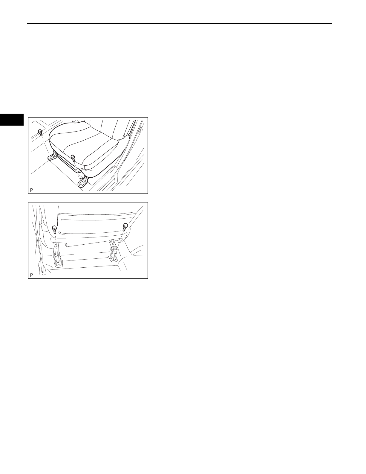
(e) Temporarily install the front side of the front seat
assembly with the 2 bolts.
(f) Move the front seat assembly fully forward by
operating the slide and vertical power seat switch
knob.
NOTICE:
Check that the seat is locked.
SE–43
SE
B140607
B139102
(g) Temporarily install the rear side of the front seat
assembly with the 2 bolts.
(h) Move the front seat assembly to the rearmost
position by operating the slide and vertical power
seat switch knob.
NOTICE:
Check that the seat is locked.
(i) Fully tighten the 2 bolts on the front side of the front
seat assembly in the order of the inner side bolt and
then the outer side bolt.
Torque: 37 N*m (377 kgf*cm, 27 ft.*lbf)
(j) Move the front seat assembly fully forward by
operating the slide and vertical power seat switch
knob.
NOTICE:
Check that the seat is locked.
(k) Fully tighten the 2 bolts on the rear side of the front
seat assembly in the order of the inner side bolt and
then the outer side bolt.
Torque: 37 N*m (377 kgf*cm, 27 ft.*lbf)

SE–44
Claw A
SEAT – FRONT SEAT ASSEMBLY (for Power Seat)
2. INSTALL INNER SEAT TRACK BRACKET COVER
(a) Slide the inner seat track bracket cover along the
seat rail toward the front of the vehicle. Engage claw
A to the seat rail.
(b) Push the inner seat track bracket cover to engage
claw B.
(2)
(1)
SE
Claw
(1)
Claw
Claw B
(2)
Claw A
Claw B
B139100E01
B139099E01
3. INSTALL SEAT TRACK COVER
(a) Slide the seat track cover along the seat rail toward
the front of the vehicle. Engage claw A to the seat
rail.
(b) Push the seat track cover to engage claw B.
4. INSTALL FRONT SEAT HEADREST ASSEMBLY
5. PERFORM ZERO POINT CALIBRATION AND
SENSITIVITY CHECK (for Front Passenger Seat)
(See page RS-242)
6. CHECK SRS WARNING LIGHT
Check the SRS warning light. (See page RS-32)
7. INSPECT FRONT SEAT ASSEMBLY
(a) Check the power seat operation.
(b) Check the seat heater operation (with seat heater
system).
(1) Turn the ignition switch on (IG).
(2) Turn the seat heater switch ON.
(3) Wait 5 minutes or more and confirm that the
seat surface becomes warm.

SEAT – REAR SEAT ASSEMBLY (for Fold Down Seat Type)
BODYSEAT
REAR SEAT ASSEMBLY (for Fold Down Seat Type)
COMPONENTS
REAR SEAT HEADREST ASSEMBLY
REAR CENTER SEAT
HEADREST ASSEMBLY
18 (184, 13)
SE–43
SE
18 (184, 13)
18 (184, 13)
REAR SIDE SEAT BACK
ASSEMBLY RH
SEPARATE TYPE REAR
SEAT BACK ASSEMBLY RH
SEPARATE TYPE REAR
SEAT BACK ASSEMBLY LH
18 (184, 13)
REAR SEAT CUSHION ASSEMBLY
REAR SIDE SEAT BACK
ASSEMBLY LH
N*m (kgf*cm, ft.*lbf)
: Specified torque
B136564E01

SE
SE–44
REAR SEAT SHOULDER BELT
GUIDE RH
REAR SEAT BELT
HOOK
SEAT – REAR SEAT ASSEMBLY (for Fold Down Seat Type)
REAR SEAT HEADREST SUPPORT
REAR SEAT BACK LOCK
BEZEL UPPER
REAR SIDE SEAT BACK
ASSEMBLY RH
REAR SEPARATE TYPE
SEAT BACK COVER
REAR CENTER SEAT
ARMREST ASSEMBLY
REAR SEAT BACK FRAME
SUB-ASSEMBLY RH
HOG RING
BUSH
REAR SEAT BACK HINGE COVER
BUSH
NO. 1 SEAT ARMREST CAP
Non-reusable part
B136565E01

REAR SEPARATE TYPE
SEAT BACK PAD
REAR SEAT SHOULDER
BELT GUIDE LH
SEAT – REAR SEAT ASSEMBLY (for Fold Down Seat Type)
REAR SEAT HEADREST SUPPORT
REAR SEAT BACK
LOCK BEZEL UPPER
SE–45
SE
REAR SEPARATE TYPE
SEAT BACK COVER
REAR SEAT BACK FRAME
SUB-ASSEMBLY LH
HOG RING
REAR SIDE SEAT BACK ASSEMBLY LH
REAR SEAT
SHOULDER
BELT GUIDE
LH
Non-reusable part
B136566E01

SE
SE–46
SEAT – REAR SEAT ASSEMBLY (for Fold Down Seat Type)
REAR BENCH TYPE SEAT CUSHION COVER
Non-reusable part
HOG RING
REAR BENCH TYPE CUSHION PAD
B136567E01

Hook
SEAT – REAR SEAT ASSEMBLY (for Fold Down Seat Type)
A
A:100 mm (3.94 in.)
or less
B134699E01
REMOVAL
1. REMOVE REAR SEAT CUSHION ASSEMBLY
(a) Detach the 2 front hooks of the seat cushion from
the vehicle body.
NOTICE:
Follow the instructions below carefully as the
cushion frame can be deformed easily.
(1) Choose a hook to detach first. Place your
hands near the hook as shown in the
illustration. Then lift the seat cushion to detach
the hook.
(2) Repeat the step above for the other hook.
(b) Remove the seat cushion.
2. REMOVE REAR SEAT HEADREST ASSEMBLY
(a) Remove the 2 rear seat headrest assemblies.
3. REMOVE REAR CENTER SEAT HEADREST
ASSEMBLY
(a) Remove the rear center seat headrest assembly.
4. REMOVE SEPARATE TYPE REAR SEAT BACK
ASSEMBLY RH
(a) Remove the 2 bolts and separate type rear seat
back assembly RH.
SE–47
SE
B134700
B136539
5. REMOVE SEPARATE TYPE REAR SEAT BACK
ASSEMBLY LH
(a) Remove the 2 bolts and separate type rear seat
back assembly LH.

SE
SE–48
SEAT – REAR SEAT ASSEMBLY (for Fold Down Seat Type)
6. REMOVE REAR SIDE SEAT BACK ASSEMBLY LH
(a) Remove the bolt and rear side seat back assembly
LH.
7. REMOVE REAR SIDE SEAT BACK ASSEMBLY RH
HINT:
Use the same procedures for the RH side and LH side.
B136561

SEAT – REAR SEAT ASSEMBLY (for Fold Down Seat Type)
DISASSEMBLY
1. REMOVE REAR BENCH TYPE SEAT CUSHION
COVER
(a) Remove the 36 hog rings.
SE–49
SE
Hog Ring
Hog Ring
B136540E01
(b) Remove the 16 hog rings and rear bench type seat
cushion cover.
B136541E01
2. REMOVE NO. 1 SEAT ARMREST CAP
(a) Using a screwdriver, remove the No. 1 seat armrest
cap.
HINT:
Tape the screwdriver tip before use.
B136542

SE–50
SEAT – REAR SEAT ASSEMBLY (for Fold Down Seat Type)
3. REMOVE REAR SEAT BACK HINGE COVER
(a) Remove the bolt and bush.
B136543
SE
(1)
(b) Remove the rear seat back hinge cover.
B136544
4. REMOVE REAR CENTER SEAT ARMREST
ASSEMBLY
(a) Remove the rear center seat armrest assembly as
shown in the illustration.
(2)
B136545E01
(b) Remove the bush.
B136546
B136563
5. REMOVE REAR SEAT BELT HOOK
(a) Remove the rear seat belt hook.
HINT:
Use the same procedures for the RH side and LH
side.

SEAT – REAR SEAT ASSEMBLY (for Fold Down Seat Type)
6. REMOVE REAR SEAT SHOULDER BELT GUIDE LH
(a) Seat Back:
(1) Remove the 2 screws and rear seat shoulder
belt guide LH.
B136554
SE–51
B136562
B139124
(b) Side Seat Back:
(1) Remove the 2 screws and rear seat shoulder
belt guide LH.
7. REMOVE REAR SEAT SHOULDER BELT GUIDE RH
(a) Remove the 2 screws and rear seat shoulder belt
guide RH.
8. REMOVE REAR SEAT BACK LOCK BEZEL UPPER
(for RH Side)
(a) Disengage the 4 claws and remove the rear seat
back lock bezel upper.
SE
B136547
B136548
9. REMOVE REAR SEA T HEADREST SUPPORT (for RH
Side)
(a) Disengage the 2 hooks and separate the rear
separate type seat back cover.

SE–52
SEAT – REAR SEAT ASSEMBLY (for Fold Down Seat Type)
(b) Remove the 7 hog rings.
SE
Hog Ring
B136549E01
(c) Disengage the 4 claws and remove the 2 rear seat
headrest supports.
10. REMOVE REAR SEAT HEADREST SUPPORT (for RH
Side)
B136550E01
11. REMOVE REAR SEAT BACK LOCK BEZEL UPPER
(for LH Side)
(a) Disengage the 4 claws and remove the rear seat
back lock bezel upper.
Hog Ring
B136555
12. REMOVE REAR SEAT HEADREST SUPPORT (for LH
Side)
(a) Disengage the 2 hooks and separate the rear
separate type seat back cover.
B136556
(b) Remove the 6 hog rings.
B136557E01

SEAT – REAR SEAT ASSEMBLY (for Fold Down Seat Type)
(c) Disengage the 2 claws and remove the rear seat
headrest support.
13. REMOVE REAR SEAT HEADREST SUPPORT (for LH
Side)
B136558E01
SE–53
B136551
B136559
14. REMOVE REAR SEAT BACK FRAME SUBASSEMBLY RH
(a) Remove the rear seat back frame sub-assembly
RH.
15. REMOVE REAR SEAT BACK FRAME SUBASSEMBLY LH
(a) Remove the rear seat back frame sub-assembly LH.
16. REMOVE REAR SEPARATE TYPE SEAT BACK
COVER (for RH Side)
(a) Remove the 7 hog rings.
SE
Hog Ring
Hog Ring
B136552E01
(b) Remove the 9 hog rings and rear separate type seat
back cover.
B136553E01

SE–54
SEAT – REAR SEAT ASSEMBLY (for Fold Down Seat Type)
17. REMOVE REAR SEPARATE TYPE SEAT BACK
COVER (for LH Side)
(a) Remove the 9 hog rings and rear separate type seat
back cover.
SE
Hog Ring
Hog Ring
B136560E01
REASSEMBLY
1. INSTALL REAR SEPARATE TYPE SEAT BACK
COVER (for LH Side)
(a) Using hog ring pliers, install the rear separate type
seat back cover with 9 new hog rings.
NOTICE:
• Be careful not to damage the cover.
• When installing the hog rings, take care to
minimize wrinkles as much as possible.
Hog Ring Pliers
B140575E01
Hog Ring
2. INSTALL REAR SEPARATE TYPE SEAT BACK
COVER (for RH Side)
(a) Using hog ring pliers, install the rear separate type
seat back cover to the seat back pad with 9 new hog
rings.
NOTICE:
• Be careful not to damage the cover.
• When installing the hog rings, take care to
minimize wrinkles as much as possible.
Hog Ring Pliers
B140576E01

Hog Ring
SEAT – REAR SEAT ASSEMBLY (for Fold Down Seat Type)
Hog Ring Pliers
B140577E01
(b) Using hog ring pliers, install the rear separate type
seat back cover to the seat back pad with 7 new hog
rings.
NOTICE:
• Be careful not to damage the cover.
• When installing the hog rings, take care to
minimize wrinkles as much as possible.
3. INSTALL REAR SEAT BACK FRAME SUBASSEMBLY RH
4. INSTALL REAR SEAT BACK FRAME SUBASSEMBLY LH
SE–55
SE
B136558E01
5. INSTALL REAR SEAT HEADREST SUPPORT (for LH
Side)
(a) Engage the 2 claws to install the 2 front seat
headrest supports.
(b) Using hog ring pliers, install the rear separate type
seat back cover to the seat back frame with 6 new
hog rings.
NOTICE:
• Be careful not to damage the cover.
• When installing the hog rings, take care to
minimize wrinkles as much as possible.
Hog Ring
Hog Ring Pliers
B140578E01

SE–56
SEAT – REAR SEAT ASSEMBLY (for Fold Down Seat Type)
6. INSTALL REAR SEAT HEADREST SUPPORT (for LH
Side)
(a) Engage the 2 claws to install the 2 front seat
headrest supports.
B136550
SE
Hog Ring
Hog Ring Pliers
B140579E01
(b) Using hog ring pliers, install the rear separate type
seat back cover to the seat back frame with 7 new
hog rings.
NOTICE:
• Be careful not to damage the cover.
• When installing the hog rings, take care to
minimize wrinkles as much as possible.
7. INSTALL REAR SEAT BACK LOCK BEZEL UPPER
8. INSTALL REAR SEAT HEADREST SUPPORT (for RH
Side)
9. INSTALL REAR SEAT HEADREST SUPPORT (for RH
Side)
10. INSTALL REAR SEAT BACK LOCK BEZEL UPPER
(for RH Side)
11. INSTALL REAR SEAT SHOULDER BELT GUIDE RH
12. INSTALL REAR SEAT SHOULDER BELT GUIDE LH
13. INSTALL REAR SEAT BELT HOOK
14. INSTALL REAR CENTER SEAT ARMREST
ASSEMBLY
15. INSTALL REAR SEAT BACK HINGE COVER
16. INSTALL NO. 1 SEAT ARMREST CAP

SEAT – REAR SEAT ASSEMBLY (for Fold Down Seat Type)
17. INSTALL REAR BENCH TYPE SEAT CUSHION
COVER
(a) Using hog ring pliers, install 16 new hog rings.
Hog Ring Pliers
SE–57
SE
Hog Ring
B140580E01
NOTICE:
• Be careful not to damage the cover.
• When installing the hog rings, take care to
minimize wrinkles as much as possible.
(b) Using hog ring pliers, install the rear bench type
seat cushion cover to the seat cushion pad with 36
new hog rings.
Hog Ring Pliers
Hog Ring
B140581E01
NOTICE:
• Be careful not to damage the cover.
• When installing the hog rings, take care to
minimize wrinkles as much as possible.

SE–58
SEAT – REAR SEAT ASSEMBLY (for Fold Down Seat Type)
INSTALLATION
1. INSTALL REAR SIDE SEAT BACK ASSEMBLY LH
(a) Install the rear side seat back assembly with the
bolt.
Torque: 18 N*m (184 kgf*cm, 13 ft.*lbf)
2. INSTALL REAR SIDE SEAT BACK ASSEMBLY RH
B136561
SE
3. INSTALL SEPARATE TYPE REAR SEAT BACK
ASSEMBLY LH
(a) Install the separate type rear seat back assembly
with the 2 bolts.
Torque: 18 N*m (184 kgf*cm, 13 ft.*lbf)
B136539
4. INSTALL SEPARATE TYPE REAR SEAT BACK
ASSEMBLY RH
(a) Install the separate type rear seat back assembly
with the 2 bolts.
Torque: 18 N*m (184 kgf*cm, 13 ft.*lbf)
5. INSTALL REAR CENTER SEAT HEADREST
ASSEMBLY
B134700
6. INSTALL REAR SEAT HEADREST ASSEMBLY

SEAT – REAR SEAT ASSEMBLY (for Fold Down Seat Type)
7. INSTALL REAR SEAT CUSHION ASSEMBLY
(a) Attach the front hooks of the bench type rear seat
cushion assembly to the vehicle body.
(b) Confirm that the seat cushion is firmly installed.
NOTICE:
When installing the bench type rear seat
cushion assembly, make sure that the seat belt
buckle is not under the bench type rear seat
cushion assembly.
SE–59
SE
Hook
B140584E01

SEAT – REAR SEAT ASSEMBLY (for Reclining Seat Type)
BODYSEAT
REAR SEAT ASSEMBLY (for Reclining Seat Type)
COMPONENTS
REAR SEAT HEADREST ASSEMBLY
SE–59
SE
18 (184, 13)
REAR SEAT
BACK COVER
18 (184, 13)
18 (184, 13)
SEPARATE TYPE REAR SEAT BACK
ASSEMBLY RH
REAR CENTER SEAT
HEADREST ASSEMBLY
CENTER SEAT BACK
ASSEMBLY
18 (184, 13)
REAR SEAT
BACK COVER
REAR SEAT CUSHION ASSEMBLY
N*m (kgf*cm, ft.*lbf)
: Specified torque
18 (184, 13)
SEPARATE TYPE REAR
SEAT BACK ASSEMBLY LH
B139095E02

SE
SE–60
REAR SEAT HEADREST
SUPPORT
REAR SEAT
SHOULDER
BELT GUIDE LH
SEAT – REAR SEAT ASSEMBLY (for Reclining Seat Type)
REAR SEAT BACK FRAME
SUB-ASSEMBLY
REAR SEPARATE TYPE
SEAT BACK PAD
REAR SEPARATE TYPE
SEAT BACK COVER
REAR SEAT BELT HOOK
18 (184, 13)
18 (184, 13)
REAR SEAT RECLINING
ADJUSTER ASSEMBLY
18 (184, 13)
RECLINING REMOTE CONTROL
LEVER SUB-ASSEMBLY
N*m (kgf*cm, ft.*lbf)
REAR DOOR OPENING
TRIM WEATHERSTRIP LH
: Specified torque
REAR DOOR SCUFF PLATE LH
B139096E01

SEAT – REAR SEAT ASSEMBLY (for Reclining Seat Type)
CENTER SEAT BACK ASSEMBLY
SE–61
SE
REAR SEAT HEADREST SUPPORT
CENTER SEAT BACK COVER
SUB-ASSEMBLY
REAR CENTER SEAT
ARMREST ASSEMBLY
HOG RING
CENTER SEAT ARMREST
PLATE INNER
BUSH
REAR SEAT CENTER
ARMREST BOX ASSEMBLY
CENTER SEAT BACK
FRAME SUB-ASSEMBLY
CENTER SEAT ARMREST
BRACKET SUB-ASSEMBLY
Non-reusable part
B139097E02

SE
SE–62
SEAT – REAR SEAT ASSEMBLY (for Reclining Seat Type)
REAR BENCH TYPE SEAT CUSHION COVER
Non-reusable part
A
Hook
:
A:100 mm (3.94 in.) or less
B139074E01
HOG RING
REAR BENCH TYPE CUSHION PAD
B136567E01
REMOVAL
1. REMOVE REAR SEAT CUSHION ASSEMBLY
(a) Detach the 2 front hooks of the seat cushion from
the vehicle body.
NOTICE:
Follow the instructions below carefully as the
cushion frame can be deformed easily.
(1) Choose a hook to detach first. Place your
hands near the hook as shown in the
illustration. Then lift the seat cushion to detach
the hook.
(2) Repeat the step above for the other hook.
(b) Remove the seat cushion.
2. REMOVE REAR SEAT HEADREST ASSEMBLY

SEAT – REAR SEAT ASSEMBLY (for Reclining Seat Type)
3. REMOVE REAR CENTER SEAT HEADREST
ASSEMBLY
4. REMOVE REAR SEAT BACK COVER
(a) Using a screwdriver, detach the claws and remove
the 2 rear seat back covers.
NOTICE:
• Tape the screwdriver tip before use.
• Use the same procedures for the RH side and
LH side.
SE–63
Clamp
B139075
B139076E01
B139081E01
SE
5. REMOVE SEPARATE TYPE REAR SEAT BACK
ASSEMBLY LH
(a) Separate the 2 rear seat belts.
(b) Disengage the 3 clamps and then separate the
cover.
B139077
(c) Remove the 2 bolts and 2 nuts and separate type
rear seat back assembly LH.

SE–64
SEAT – REAR SEAT ASSEMBLY (for Reclining Seat Type)
6. REMOVE SEPARATE TYPE REAR SEAT BACK
ASSEMBLY RH
(a) Separate the rear seat belt.
B139078E01
SE
Clamp
(b) Disengage the 3 clamps and then separate the
cover.
B139082E01
(c) Remove the 2 bolts and 2 nuts and separate type
rear seat back assembly RH.
B139079
7. REMOVE CENTER SEAT BACK ASSEMBLY
(a) Remove the 2 bolts and center seat back assembly.
B139080

SEAT – REAR SEAT ASSEMBLY (for Reclining Seat Type)
DISASSEMBLY
1. REMOVE REAR BENCH TYPE SEAT CUSHION
COVER
(a) Remove the 36 hog rings.
SE–65
SE
Hog Ring
Hog Ring
B136540E01
(b) Remove the 16 hog rings and rear bench type seat
cushion cover.
B136541E01
2. REMOVE REAR SEAT SHOULDER BELT GUIDE LH
(a) Remove the 4 screws and 2 rear seat shoulder belt
guides LH.
B139085

SE–66
SEAT – REAR SEAT ASSEMBLY (for Reclining Seat Type)
3. REMOVE REAR SEAT HEADREST SUPPORT (for LH
Side)
(a) Disengage the hook.
SE
Hook
B139086E01
(b) Disengage the 2 claws and remove the rear seat
headrest support.
4. REMOVE REAR SEAT HEADREST SUPPORT (for LH
Side)
B139098
5. REMOVE REAR SEPARATE TYPE SEAT BACK
COVER
(a) Disengage the hooks and remove the rear seat
back assembly.
B139087
B139088
(b) Remove the rear seat belt hook.
(c) Remove the rear separate type seat back cover.

SEAT – REAR SEAT ASSEMBLY (for Reclining Seat Type)
6. REMOVE REAR CENTER SEAT ARMREST
ASSEMBLY
(a) Remove the 2 bolts and 2 bushes.
(b) Remove the rear center seat armrest assembly.
B139089
SE–67
Hog Ring
B139090E01
B139091E01
7. REMOVE REAR SEAT HEADREST SUPPORT
(a) Disengage the 2 claws and remove the rear seat
headrest support.
8. REMOVE REAR SEAT HEADREST SUPPORT
HINT:
Use the same procedures for the RH side and LH side.
9. REMOVE CENTER SEAT BACK COVER SUBASSEMBLY
(a) Remove the 2 hog rings.
(b) Disengage the hooks and remove the center seat
back cover sub-assembly.
10. REMOVE CENTER SEAT ARMREST PLATE INNER
(a) Disengage the 1 1 claws and the n remove the center
seat armrest plate inner.
SE
B139092

SE–68
SEAT – REAR SEAT ASSEMBLY (for Reclining Seat Type)
11. REMOVE REAR SEAT CENTER ARMREST BOX
ASSEMBLY
(a) Remove the 2 nuts.
(b) Disengage the 2 claws and then remove the rear
seat center armrest box assembly.
12. REMOVE REAR DOOR SCUFF PLATE LH (See page
IR-24)
13. REMOVE REAR DOOR OPENING TRIM
B139093
WEATHERSTRIP LH
SE
14. REMOVE RECLINING REMOTE CONTROL LEVER
SUB-ASSEMBLY
(a) Remove the bolt.
(b) Disengage the 2 clips and the claw and then
separate the reclining remote control lever subassembly.
B139083
(c) Separate the rear seat reclining control cable and
remove the reclining remote control lever subassembly.
B139084
15. REMOVE REAR SEAT RECLINING ADJUSTER
ASSEMBLY
(a) Remove the 4 bolts and rear seat reclining adjuster
assembly.
B139094

(3)
(1)
SEAT – REAR SEAT ASSEMBLY (for Reclining Seat Type)
REASSEMBLY
HINT:
A bolt without a torque specification is shown in the standard
bolt chart. (See page SS-2)
1. INSTALL REAR SEAT RECLINING ADJUSTER
ASSEMBLY
(a) Install the rear seat reclining adjuster assembly with
the 4 bolts.
Torque: 18 N*m (184 kgf*cm, 13 ft.*lbf)
NOTICE:
(2)
(4)
B139094E01
2. INSTALL RECLINING REMOTE CONTROL LEVER
Tighten the bolts in the order shown in the
illustration to install the rear seat reclining
adjuster assembly.
SUB-ASSEMBLY
(a) Install the rear seat reclining control cable.
SE–69
SE
Plate A
B139084
B139083
Upper most
position
(b) Engage the 2 clips and claw and then install the
reclining remote control lever sub-assembly.
(c) Install the bolt.
Torque: 18 N*m (184 kgf*cm, 13 ft.*lbf)
(d) Adjust the control lever to set the rear reclining
adjuster assembly to its upper most position.
(e) Pull plate A toward the front of the vehicle to lock
the plate.
3. INSTALL REAR DOOR OPENING TRIM
WEATHERSTRIP LH
4. INSTALL REAR DOOR SCUFF PLATE LH (See page
IR-56)
5. INSTALL REAR SEAT CENTER ARMREST BOX
ASSEMBLY
B144036E01
6. INSTALL CENTER SEAT ARMREST PLATE INNER

SE–70
SEAT – REAR SEAT ASSEMBLY (for Reclining Seat Type)
7. INSTALL CENTER SEAT BACK COVER SUBASSEMBLY
(a) Install the center seat back cover sub-assembly with
the hook.
(b) Using hog ring pliers, install 2 new hog rings.
8. INSTALL REAR SEAT HEADREST SUPPORT
9. INSTALL REAR SEAT HEADREST SUPPORT
10. INSTALL REAR CENTER SEAT ARMREST
ASSEMBLY
SE
Hog Ring
Hog Ring Pliers
B140590E01
11. INSTALL REAR SEPARATE TYPE SEAT BACK
COVER
12. INSTALL REAR SEAT HEADREST SUPPORT (for LH
Side)
13. INSTALL REAR SEAT HEADREST SUPPORT (for LH
Side)
14. INSTALL REAR BENCH TYPE SEAT CUSHION
COVER
(a) Using hog ring pliers, install 16 new hog rings.
Hog Ring Pliers
Hog Ring
B140580E01
NOTICE:
• Be careful not to damage the cover.
• When installing the hog rings, take care to
minimize wrinkles as much as possible.

Hog Ring
SEAT – REAR SEAT ASSEMBLY (for Reclining Seat Type)
(b) Using hog ring pliers, install the rear bench type
seat cushion cover to the seat cushion pad with 36
new hog rings.
INSTALLATION
SE–71
Hog Ring Pliers
SE
B140581E01
B140592
B139079
1. INSTALL CENTER SEAT BACK ASSEMBLY
(a) Install the center seat back assembly with the 2
bolts.
Torque: 18 N*m (184 kgf*cm, 13 ft.*lbf)
2. INSTALL SEPARATE TYPE REAR SEAT BACK
ASSEMBLY RH
(a) Install the separate type rear seat back assembly
RH with the 2 bolts and 2 nuts.
Torque: 18 N*m (184 kgf*cm, 13 ft.*lbf)
(b) Engage the 3 clamps and install the cover.
Clamp
B139082E01

SE–72
SEAT – REAR SEAT ASSEMBLY (for Reclining Seat Type)
(c) Install the rear seat belt.
B139078E01
SE
Clamp
3. INSTALL SEPARATE TYPE REAR SEAT BACK
ASSEMBLY LH
(a) Install the separate type rear seat back assembly
LH with the 2bolts and 2 nuts.
Torque: 18 N*m (184 kgf*cm, 13 ft.*lbf)
B139077
(b) Engage the 3 clamps and install the cover.
B139081E01
(c) Install the 2 rear seat belts.
B139076E01
4. INSTALL REAR SEAT BACK COVER
5. INSTALL REAR CENTER SEAT HEADREST
ASSEMBLY
6. INSTALL REAR SEAT HEADREST ASSEMBLY

Hook
:
SEAT – REAR SEAT ASSEMBLY (for Reclining Seat Type)
7. INSTALL REAR SEAT CUSHION ASSEMBLY
(a) Attach the front hooks of the bench type rear seat
cushion assembly to the vehicle body.
(b) Confirm that the seat cushion is firmly installed.
NOTICE:
When installing the bench type rear seat
cushion assembly, make sure that the seat belt
buckle is not under the bench type rear seat
cushion assembly.
B140591E01
SE–73
SE

SE
SE–74
BODYSEAT
SEAT – REAR SEAT ASSEMBLY (for Fixed Type)
REAR SEAT ASSEMBLY (for Fixed Type)
COMPONENTS
REAR SEAT HEADREST ASSEMBLY
REAR CENTER SEAT
HEADREST ASSEMBLY
REAR SEAT BACK ASSEMBLY
18 (184, 13)
REAR SEAT CUSHION ASSEMBLY
18 (184, 13)
N*m (kgf*cm, ft.*lbf)
: Specified torque
B136589E01

SEAT – REAR SEAT ASSEMBLY (for Fixed Type)
ARMREST ASSEMBLY
SE–75
SE
REAR SEAT
CENTER ARMREST BOX
ASSEMBLY
CUP HOLDER
INNER CENTER SEAT
ARMREST PLATE
CENTER SEAT ARMREST
BRACKET SUB-ASSEMBLY
BUSH
BUSH
B136590E02

SE
SE–76
REAR SEAT SHOULDER
BELT GUIDE RH
REAR SEAT HEADREST SUPPORT
REAR BENCH TYPE
SEAT BACK PAD SUB-ASSEMBLY
SEAT – REAR SEAT ASSEMBLY (for Fixed Type)
REAR SEAT SHOULDER BELT GUIDE LH
REAR BENCH TYPE
SEAT BACK COVER
Non-reusable part
HOG RING
REAR BENCH TYPE
SEAT CUSHION COVER
REAR BENCH TYPE
SEAT CUSHION PAD SUB-ASSEMBLY
HOG RING
B136591E01

Hook
SEAT – REAR SEAT ASSEMBLY (for Fixed Type)
A:100 mm (3.94 in.)
or less
B136575E01
REMOVAL
1. REMOVE REAR SEAT CUSHION ASSEMBLY
(a) Detach the 2 front hooks of the seat cushion from
the vehicle body.
NOTICE:
Follow the instructions below carefully as the
cushion frame can be deformed easily.
(1) Choose a hook to detach first. Place your
hands near the hook as shown in the
illustration. Then lift the seat cushion to detach
the hook.
(2) Repeat the step above for the other hook.
(b) Remove the rear seat cushion assembly.
2. REMOVE REAR SEAT HEADREST ASSEMBLY
3. REMOVE REAR CENTER SEAT HEADREST
ASSEMBLY
4. REMOVE REAR SEAT BACK ASSEMBLY
(a) Remove the 3 rear seat belts from the 3 rear seat
shoulder belt guides.
SE–77
SE
B136576
B136577
(b) Remove the 4 bolts and rear seat back assembly.

SE
SE–78
SEAT – REAR SEAT ASSEMBLY (for Fixed Type)
DISASSEMBLY
1. REMOVE REAR BENCH TYPE SEAT CUSHION
COVER
(a) Remove the 36 hog rings.
Hog Ring
Hog Ring
B136578E01
(b) Remove the 14 hog rings and rear bench type seat
cushion cover from the seat cushion frame (with
pad).
B136579E01

SEAT – REAR SEAT ASSEMBLY (for Fixed Type)
2. REMOVE ARMREST ASSEMBLY
(a) Remove the 2 nuts.
(b) Disengage the 2 claws and remove the armrest
assembly.
B136580
3. REMOVE CENTER SEAT ARMREST BRACKET SUBASSEMBLY
(a) Remove the 2 bolts and bushes.
(b) Remove the center seat armrest bracket sub-
assembly.
SE–79
SE
B136581
B136582
B136583
4. REMOVE CUP HOLDER
(a) Remove the 2 mats.
(b) Remove the 2 screws and cup holder.

SE
SE–80
SEAT – REAR SEAT ASSEMBLY (for Fixed Type)
5. REMOVE INNER CENTER SEAT ARMREST PLATE
(a) Disengage the 11 claws and remove the inner
center seat armrest plate.
6. REMOVE REAR SEAT HEADREST SUPPORT
(a) Disengage the 6 claws and remove the 3 rear seat
headrest supports.
B136584
B136586
B136585
7. REMOVE REAR SEAT HEADREST SUPPORT
8. REMOVE REAR SEAT SHOULDER BELT GUIDE RH
(a) Remove the 2 screws and rear seat shoulder belt
guide RH.
9. REMOVE REAR SEAT SHOULDER BELT GUIDE LH
HINT:
Use the same procedures for the RH side and LH side.

SEAT – REAR SEAT ASSEMBLY (for Fixed Type)
10. REMOVE REAR BENCH TYPE SEAT BACK COVER
(a) Remove the 44 hog rings and strap guide.
SE–81
Rear Seat
Belt Hook
:
Hog Ring
Rear Seat
Belt Hook
B136587E02
(b) Remove the 2 rear seat belt hooks.
(c) Remove the 20 hog rings and seat back cover from
the seat back frame (with pad).
SE
Hog Ring
B136588E01

SE
SE–82
SEAT – REAR SEAT ASSEMBLY (for Fixed Type)
REASSEMBLY
HINT:
A bolt without a torque specification is shown in the standard
bolt chart. (See page SS-2)
1. INSTALL REAR BENCH TYPE SEAT BACK COVER
NOTICE:
• Be careful not to damage the cover.
• When installing the hog rings, take care to
minimize wrinkles as much as possible.
(a) Using hog ring pliers, install 20 new hog rings.
Hog Ring Pliers
:
Hog Ring
B140586E01

SEAT – REAR SEAT ASSEMBLY (for Fixed Type)
(b) Using hog ring pliers, install the rear bench type
seat back cover to the seat back frame (with pad)
with 44 new hog rings.
SE–83
:
Hog Ring
Rear Seat
Belt Hook
Rear Seat
Belt Hook
Hog Ring Pliers
SE
B140585E01
2. INSTALL REAR SEAT SHOULDER BELT GUIDE LH
3. INSTALL REAR SEAT SHOULDER BELT GUIDE RH
4. INSTALL REAR SEAT HEADREST SUPPORT
5. INSTALL REAR SEAT HEADREST SUPPORT
6. INSTALL INNER CENTER SEAT ARMREST PLATE
7. INSTALL CUP HOLDER
8. INSTALL CENTER SEAT ARMREST BRACKET SUBASSEMBLY
9. INSTALL ARMREST ASSEMBLY
10. INSTALL REAR BENCH TYPE SEAT CUSHION
COVER
NOTICE:
• Be careful not to damage the cover.
• When installing the hog rings, take care to
minimize wrinkles as much as possible.

SE
SE–84
SEAT – REAR SEAT ASSEMBLY (for Fixed Type)
(a) Using hog ring pliers, install 14 new hog rings.
Hog Ring Pliers
Hog Ring
Hog Ring
B140587E01
(b) Using hog ring pliers, install the rear seat cushion
cover to the rear seat cushion pad with 36 new hog
rings.
Hog Ring Pliers
B140588E01
INSTALLATION
B136577
1. INSTALL REAR SEAT BACK ASSEMBLY
(a) Place the seat back in the cabin.
NOTICE:
Be careful not to damage the vehicle body.
(b) Install the rear seat back assembly with the 4 bolts.
Torque: 18 N*m (184 kgf*cm, 13 ft.*lbf)

SEAT – REAR SEAT ASSEMBLY (for Fixed Type)
(c) Pass the 3 seat belts through and close the cap of
the 2 rear seat shoulder belt guides.
(d) Install the floor anchor part with the bolt.
2. INSTALL REAR CENTER SEAT HEADREST
ASSEMBLY
3. INSTALL REAR SEAT HEADREST ASSEMBLY
B136576
SE–85
Hook
B140589E01
4. INSTALL REAR SEAT CUSHION ASSEMBLY
(a) Attach the 2 front hooks of the seat cushion to the
vehicle body.
(b) Confirm that the seat cushion is firmly installed.
NOTICE:
When installing the seat cushion, make sure the
seat belt buckle is not under the seat cushion.
SE

SEAT – POWER SEAT SWITCH
BODYSEAT
POWER SEAT SWITCH
COMPONENTS
FRONT SEAT HEADREST ASSEMBLY
SE–85
SE
INNER SEAT TRACK
BRACKET COVER
FRONT SEAT ASSEMBLY
37 (377, 27)
SEAT TRACK COVER
37 (377, 27)
37 (377, 27)
N*m (kgf*cm, ft.*lbf)
: Specified torque
B134694E01

SE
SE–86
SEAT – POWER SEAT SWITCH
POWER SEAT SWITCH
FRONT SEAT CUSHION SHIELD ASSEMBLY
SLIDE AND VERTICAL
POWER SEAT SWITCH KNOB
RECLINING POWER
SEAT SWITCH KNOB
B136569E01

SEAT – POWER SEAT SWITCH
REMOVAL
1. REMOVE FRONT SEAT HEADREST ASSEMBLY
2. REMOVE SEAT TRACK COVER (See page SE-30)
3. REMOVE INNER SEAT TRACK BRACKET COVER
(See page SE-30)
4. REMOVE FRONT SEAT ASSEMBLY (See page SE-30)
5. REMOVE RECLINING POWER SEAT SWITCH KNOB
(See page SE-31)
SE–87
Slide Switch
Front Vertical Switch
U7
RCLF
E
FUP
SLDF
LDWN
Reclining Switch
Lifter Switch
RCLR
LUP
SLDR
B
B134677
FDWN
B105970E08
6. REMOVE SLIDE AND VERTICAL POWER SEAT
SWITCH KNOB (See page SE-31)
7. REMOVE FRONT SEAT CUSHION SHIELD
ASSEMBLY (See page SE-32)
8. REMOVE POWER SEAT SWITCH
(a) Remove the 3 screws.
(b) Disconnect the connector and remove the power
seat switch.
INSPECTION
1. INSPECT FRONT POWER SEAT SWITCH LH
(a) Measure the resistance between the specified
terminals when each switch is operated.
Standard resistance (Slide switch)
Tester Connection Switch Condition Specified Condition
U7-1 (B) - U7-9 (SLDF) FRONT Below 1 Ω
U7-4 (E) - U7-6 (SLDR) FRONT Below 1 Ω
U7-1 (B) - U7-6 (SLDR) FRONT 10 kΩ or higher
U7-4 (E) - U7-9 (SLDF) FRONT 10 kΩ or higher
U7-4 (E) - U7-6 (SLDR) OFF Below 1 Ω
U7-4 (E) - U7-9 (SLDF) OFF Below 1 Ω
U7-1 (B) - U7-6 (SLDR) OFF 10 kΩ or higher
U7-1 (B) - U7-9 (SLDF) OFF 10 kΩ or higher
U7-1 (B) - U7-6 (SLDR) REAR Below 1 Ω
U7-4 (E) - U7-9 (SLDF) REAR Below 1 Ω
U7-1 (B) - U7-9 (SLDF) REAR 10 kΩ or higher
U7-4 (E) - U7-6 (SLDR) REAR 10 kΩ or higher
Standard resistance (Front vertical switch)
Tester Connection Switch Condition Specified Condition
U7-1 (B) - U7-10 (FUP) UP Below 1 Ω
U7-4 (E) - U7-5 (FDWN) UP Below 1 Ω
U7-1 (B) - U7-5 (FDWN) UP 10 kΩ or higher
U7-4 (E) - U7-10 (FUP) UP 10 kΩ or higher
U7-4 (E) - U7-5 (FDWN) OFF Below 1 Ω
SE

SE
SE–88
SEAT – POWER SEAT SWITCH
Tester Connection Switch Condition Specified Condition
U7-4 (E) - U7-10 (FUP) OFF Below 1 Ω
U7-1 (B) - U7- 5 (FDWN) OFF 10 kΩ or higher
U7-1 (B) - U7-10 (FUP) OFF 10 kΩ or higher
U7-1 (B) - U7-5 (FDWN) DOWN Below 1 Ω
U7-4 (E) - U7-10 (FUP) DOWN Below 1 Ω
U7-1 (B) - U7-10 (FUP) DOWN 10 kΩ or higher
U7-4 (E) - U7-5 (FDWN) DOWN 10 kΩ or higher
Standard resistance (Lifter switch)
Tester Connection Switch Condition Specified Condition
U7-1 (B) - U7-7 (LUP) UP Below 1 Ω
U7-4 (E) - U7-8 (LDWN) UP Below 1 Ω
U7-1 (B) - U7-8 (LDWN) UP 10 kΩ or higher
U7-4 (E) - U7-7 (LUP) UP 10 kΩ or higher
U7-4 (E) - U7-7 (LUP) OFF Below 1 Ω
U7-4 (E) - U7-8 (LDWN) OFF Below 1 Ω
U7-1 (B) - U7-7 (LUP) OFF 10 kΩ or higher
U7-1 (B) - U7-8 (LDWN) OFF 10 kΩ or higher
U7-1 (B) - U7-8 (LDWN) DOWN Below 1 Ω
U7-4 (E) - U7-7 (LUP) DOWN Below 1 Ω
U7-1 (B) - U7-7 (LUP) DOWN 10 kΩ or higher
U7-4 (E) - U7-8 (LDWN) DOWN 10 kΩ or higher
Standard resistance (Reclining switch)
Tester Connection Switch Condition Specified Condition
U7-1 (B) - U7-3 (RCLF) FRONT Below 1 Ω
U7-4 (E) - U7-2 (RCLR) FRONT Below 1 Ω
U7-1 (B) - U7-2 (RCLR) FRONT 10 kΩ or higher
U7-4 (E) -U7-3 (RCLF) FRONT 10 kΩ or higher
U7-4 (E) - U7-2 (RCLR) OFF Below 1 Ω
U7-4 (E) - U7-3 (RCLF) OFF Below 1 Ω
U7-1 (B) - U7-3 (RCLF) OFF 10 kΩ or higher
U7-1 (B) - U7-2 (RCLR) OFF 10 kΩ or higher
U7-1 (B) - U7-2 (RCLR) REAR Below 1 Ω
U7-4 (E) - U7-3 (RCLF) REAR Below 1 Ω
U7-1 (B) - U7-3 (RCLF) REAR 10 kΩ or higher
U7-4 (E) - U7-2 (RCLR) REAR 10 kΩ or higher
If the result is not as specified, replace the switch.

Reclining Switch
RCLF
T8
E
SLDF
Slide Switch
RCLR
SLDR
SEAT – POWER SEAT SWITCH
2. INSPECT FRONT POWER SEAT SWITCH RH
(a) Measure the resistance between the specified
terminals when each switch is operated.
Standard resistance (Slide switch)
Tester Connection Switch Condition Specified Condition
T8-1 (B) - T8-9 (SLDF) FRONT Below 1 Ω
T8-4 (E) - T8-6 (SLDR) FRONT Below 1 Ω
T8-1 (B) - T8-6 (SLDR) FRONT 10 kΩ or higher
T8-4 (E) - T8-9 (SLDF) FRONT 10 kΩ or higher
T8-4 (E) - T8-6 (SLDR) OFF Below 1 Ω
T8-4 (E) - T8-9 (SLDF) OFF Below 1 Ω
B
T8-1 (B) - T8-6 (SLDR) OFF 10 kΩ or higher
T8-1 (B) - T8-9 (SLDF) OFF 10 kΩ or higher
T8-1 (B) - T8-6 (SLDR) REAR Below 1 Ω
T8-4 (E) - T8-9 (SLDF) REAR Below 1 Ω
T8-1 (B) - T8-9 (SLDF) REAR 10 kΩ or higher
T8-4 (E) - T8-6 (SLDR) REAR 10 kΩ or higher
Standard resistance (Reclining switch)
B105969E06
Tester Connection Switch Condition Specified Condition
T8-1 (B) - T8-3 (RCLF) FRONT Below 1 Ω
T8-4 (E) - T8-2 (RCLR) FRONT Below 1 Ω
T8-1 (B) - T8-2 (RCLR) FRONT 10 kΩ or higher
T8-4 (E) - T8-3 (RCLF) FRONT 10 kΩ or higher
T8-4 (E) - T8-2 (RCLR) OFF Below 1 Ω
T8-4 (E) - T8-3 (RCLF) OFF Below 1 Ω
T8-1 (B) - T8- 3 (RCLF) OFF 10 kΩ or higher
T8-1 (B) - T8-2 (RCLR) OFF 10 kΩ or higher
T8-1 (B) - T8-2 (RCLR) REAR Below 1 Ω
T8-4 (E) - T8-3 (RCLF) REAR Below 1 Ω
T8-1 (B) - T8-3 (RCLF) REAR 10 kΩ or higher
T8-4 (E) - T8-2 (RCLR) REAR 10 kΩ or higher
SE–89
SE
B134677
If the result is not as specified, replace the switch.
INSTALLATION
1. INSTALL POWER SEAT SWITCH
(a) Install the power seat switch with the 3 screws.
(b) Connect the connector.
2. INSTALL FRONT SEAT CUSHION SHIELD
ASSEMBLY
3. INSTALL SLIDE AND VERTICAL POWER SEAT
SWITCH KNOB
4. INSTALL RECLINING POWER SEAT SWITCH KNOB
5. INSTALL FRONT SEAT ASSEMBLY (See page SE-41)
6. INSTALL INNER SEAT TRACK BRACKET COVER
(See page SE-42)
7. INSTALL SEAT TRACK COVER (See page SE-42)

SE–90
SEAT – FRONT SEAT FRAME WITH ADJUSTER
SE
U1
U2
B081621E19
B081621E20
FRONT SEAT FRAME WITH
ADJUSTER
INSPECTION
1. INSPECT FRONT SEAT FRAME WITH ADJUSTER LH
(a) Check operation of the seat frame (slide motor).
(1) Check if the seat frame moves smoothly when
the battery is connected to the slide motor
connector terminals.
OK
Measurement Condition Operational Direction
Battery positive (+) → U1-1
Battery negative (-) → U1-2
Battery positive (+) → U1-2
Battery negative (-) → U1-1
If the result is not as specified, replace the seat
frame with adjuster.
(b) Check operation of the seat frame (front vertical
motor).
(1) Check if the seat frame moves smoothly when
the battery is connected to the front vertical
motor connector terminals.
OK
Measurement Condition Operational Direction
Battery positive (+) → U2-1
Battery negative (-) → U2-2
Battery positive (+) → U2-2
Battery negative (-) → U2-1
Forward
Backward
Upward
Downward
U3
B081621E21
If the result is not as specified, replace the seat
frame with adjuster.
(c) Check operation of the seat frame (reclining motor).
(1) Check if the seat frame moves smoothly when
the battery is connected to the reclining motor
connector terminals.
OK
Measurement Condition Operational Direction
Battery positive (+) → U3-2
Battery negative (-) → U3-1
Battery positive (+) → U3-1
Battery negative (-) → U3-2
Forward
Backward
If the result is not as specified, replace the seat
frame with adjuster.

U4
T1
SEAT – FRONT SEAT FRAME WITH ADJUSTER
(d) Check operation of the seat frame (lifter motor).
(1) Check if the seat frame moves smoothly when
the battery is connected to the lifter motor
connector terminals.
OK
Measurement Condition Operational Direction
Battery positive (+) → U4-2
Battery negative (-) → U4-1
B081621E22
Battery positive (+) → U4-1
Battery negative (-) → U4-2
If the result is not as specified, replace the seat
frame with adjuster.
2. INSPECT FRONT SEAT FRAME WITH ADJUSTER RH
(a) Check operation of the seat frame (slide motor).
(1) Check if the seat frame moves smoothly when
the battery is connected to the slide motor
connector terminals.
OK
Measurement Condition Operational Direction
Battery positive (+) → T1-2
Battery negative (-) → T1-1
B081621E23
Battery positive (+) → T1-1
Battery negative (-) → T1-2
SE–91
Upward
Downward
SE
Forward
Backward
T3
B081621E24
If the result is not as specified, replace the seat
frame with adjuster.
(b) Check operation of the seat frame (reclining motor).
(1) Check if the seat frame moves smoothly when
the battery is connected to the reclining motor
connector terminals.
OK
Measurement Condition Operational Direction
Battery positive (+) → T3-2
Battery negative (-) → T3-1
Battery positive (+) → T3-1
Battery negative (-) → T3-2
Forward
Backward
If the result is not as specified, replace the seat
frame with adjuster.

SE
SE–92
BODYSEAT
SEAT – FRONT POWER SEAT LUMBAR SWITCH
FRONT POWER SEAT LUMBAR SWITCH
COMPONENTS
FRONT SEAT HEADREST ASSEMBLY
INNER SEAT TRACK
BRACKET COVER
FRONT SEAT ASSEMBLY
37 (377, 27)
SEAT TRACK COVER
37 (377, 27)
37 (377, 27)
N*m (kgf*cm, ft.*lbf)
: Specified torque
B134694E01

SEAT – FRONT POWER SEAT LUMBAR SWITCH
SE–93
SE
FRONT SEAT CUSHION SHIELD ASSEMBLY
SLIDE AND VERTICAL POWER SEAT
SWITCH KNOB
FRONT POWER SEAT
LUMBAR SWITCH
RECLINING POWER
SEAT SWITCH KNOB
B136570E01
 Loading...