

FOREWORD
This wiring diagram manual has been prepared to provide
information on the electrical system of the 2007 CAMRY.
Applicable models: GSV40 Series
ACV40 Series
Refer to the following manuals for additional service
specifications and repair procedures for these models:
Manual Name
D 2007 CAMRY Repair Manual
D 2007 CAMRY New Car Features
All information in this manual is based on the latest product
information at the time of publication. However, specifications
and procedures are subject to change without notice.
Pub. No.
RM0250U
NM0250U
NOTICE
Always follow the directions given in the above repair manuals when handling
supplemental restraint system components (such as removal, installation,
inspection, etc.) in order to prevent accidents and supplemental restraint
system malfunction.
E2006
All rights reserved. This book may not be
reproduced or copied, in whole or in part, without
the written permission of Toyota Motor
Corporation.
First Printing : Jan. 13, 2006 01–060113–00

2007 CAMRY
ELECTRICAL WIRING DIAGRAM
Section Code
INTRODUCTION A. . . . . . . . . . . . . . . . . . . . . . . . . . . . . . . 2
HOW TO USE THIS MANUAL B. . . . . . . . . . . . . . . . . . .
TROUBLESHOOTING C. . . . . . . . . . . . . . . . . . . . . . . . . .
ABBREVIATIONS D. . . . . . . . . . . . . . . . . . . . . . . . . . . . .
GLOSSARY OF TERMS AND SYMBOLS E. . . . . . . . . 18
RELAY LOCATIONS F. . . . . . . . . . . . . . . . . . . . . . . . . . .
ELECTRICAL WIRING ROUTING G. . . . . . . . . . . . . . .
SYSTEM CIRCUITS H. . . . . . . . . . . . . . . . . . . . . . . . . . . .
Page
3
12
17
20
48
70
GROUND POINT I. . . . . . . . . . . . . . . . . . . . . . . . . . . . . . .
POWER SOURCE (Current Flow Chart) J. . . . . . . . .
CONNECTOR LIST K. . . . . . . . . . . . . . . . . . . . . . . . . . . .
PART NUMBER OF CONNECTORS L. . . . . . . . . . . . .
OVERALL ELECTRICAL WIRING DIAGRAM M. . . . .
396
404
414
436
440
CAMRY (EM0250U)
1

A INTRODUCTION
A
H
This manual consists of the following 13 sections:
No. Section Description
INDEX Index of the contents of this manual.
INTRODUCTION Brief explanation of each section.
HOW TO USE THIS
B
MANUAL
TROUBLE–
C
SHOOTING
D ABBREVIATIONS Defines the abbreviations used in this manual.
GLOSSARY OF
TERMS AND
E
SYMBOLS
Instructions on how to use this manual.
Describes the basic inspection procedures for electrical circuits.
Defines the symbols and functions of major parts.
F RELAY LOCATIONS
ELECTRICAL
G
WIRING ROUTING
INDEX Index of the system circuits.
SYSTEM CIRCUITS
I GROUND POINT Shows ground positions of all parts described in this manual.
POWER SOURCE
J
(Current Flow Chart)
K CONNECTOR LIST
PART NUMBER OF
L
CONNECTORS
Shows position of the Electronic Control Unit, Relays, Relay Block, etc.
This section is closely related to the system circuit.
Describes position of Parts Connectors, Splice points, Ground points, etc.
This section is closely related to the system circuit.
Electrical circuits of each system are shown from the power supply through ground
points. Wiring connections and their positions are shown and classified by code
according to the connection method. (Refer to the section, ”How to use this manual”).
The ”System Outline” and ”Service Hints” useful for troubleshooting are also contained
in this section.
Describes power distribution from the power supply to various electrical loads.
Describes the form of the connectors for the parts appeared in this book.
This section is closely related to the system circuit.
Indicates the part number of the connectors used in this manual.
OVERALL
ELECTRICAL
M
WIRING DIAGRAM
Provides circuit diagrams showing the circuit connections.
2
CAMRY (EM0250U)

HOW TO USE THIS MANUAL B
This manual provides information on the electrical circuits installed on vehicles by
dividing them into a circuit for each system.
The actual wiring of each system circuit is shown from the point where the power
source is received from the battery as far as each ground point. (All circuit
diagrams are shown with the switches in the OFF position.)
When troubleshooting any problem, first understand the operation of the circuit
where the problem was detected (see System Circuit section), the power source
supplying power to that circuit (see Power Source section), and the ground points
(see Ground Point section). See the System Outline to understand the circuit
operation.
When the circuit operation is understood, begin troubleshooting of the problem
circuit to isolate the cause. Use Relay Location and Electrical Wiring Routing
sections to find each part, junction block and wiring harness connectors, wiring
harness and wiring harness connectors and ground points of each system circuit.
Internal wiring for each junction block is also provided for better understanding of
connection within a junction block.
Wiring related to each system is indicated in each system circuit by arrows
(from__, to__). When overall connections are required, see the Overall Electrical
Wiring Diagram at the end of this manual.
CAMRY (EM0250U)
3

B HOW TO USE THIS MANUAL
* The system shown here is an EXAMPLE ONL Y . It is different to the actual
circuit shown in the SYSTEM CIRCUITS SECTION.
[A]
Stop Light
[D]
[B]
G – W
Skid Control ECU
with Actuator
(BAT)
2
1
W – RG – W
2
1
G – W
15A
STOP
H6
Stop Lamp SW
(IG)
7.5A
GAUGE
34
IB
R
[M]
(S/D)
[C]
CH114
LL
(W/G)
CH1
15
L
[E]
(S/D) (S/D)
[F]
IB
R – L
3C
7
[G]
3C
15
R – L
4
Rear
Lights
H7
13
Y – G
Combination Meter
H4
7
Light Failure Sensor
12
48
11
[H]
1
G – R
HJ1
G – R G – R
4
Stop
Rear Combination Lamp (RH)
3
W – B G – R
J7
1
HJ1
3
6
W – BW – B
W – B
H1 H2
[N]
Stop
Rear Combination Lamp (LH)
H9
[K]
[I]
(Shielded)
[J]
G – B
2
1
W – B
H17
Center Stop
Lamp
W – B
4
50
[L]
CAMRY (EM0250U)
B
[A] : System Title
[B] : Indicates a Relay Block. No shading is used and
only the Relay Block No. is shown to distinguish it
from the J/B
Example: Indicates Relay Block No.1
[C] : ( ) is used to indicate different wiring and
connector, etc. when the vehicle model, engine
type, or specification is different.
[D] : Indicates related system.
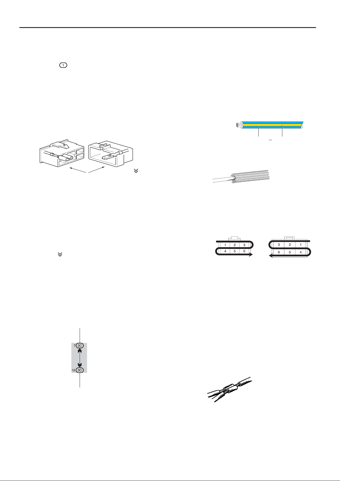
[E] : Indicates the code for the (male and female)
connectors which are used to join two wire
harnesses. The connector code consists of two
alphabetical and one numerical characters.
Female Male ( )
The first character of the connector code indicates
the alphabetical code allocated to the wire harness
which has the female connector, and the second
shows that of the wire harness which has the male
connector.
The third character indicates a serial number used
to distinguish between the wire harness
combinations in cases when more than one of the
same combination of wire harnesses exist
(e.g. CH1 and CH2).
[H] : Indicates the wiring color.
Wire colors are indicated by an alphabetical code.
B = Black W = White BR = Brown
L = Blue V = V iolet SB = Sky Blue
R = Red G = Green LG = Light Green
P = Pink Y = Yellow GR= Gray
O = Orange
The first letter indicates the basic wire color and the
second letter indicates the color of the stripe.
Example: L – Y
L
(Blue)Y(Yellow)
[I] : Indicates a shielded cable.
[J] : Indicates the pin number of the connector.
The numbering system is different for female and
male connectors.
Example:
Numbered in other
from upper left to
lower right
Numbered in other
from upper right to
lower left
Symbol (
) indicates the male terminal connector.
Numbers outside connector codes indicate the pin
numbers of both male and female connectors.
[F] : Represents a part (all parts are shown in sky blue).
The code is the same as the code used in parts
position.
[G] : Junction Block (The number in the circle is the J/B
No. and the connector code is shown beside it).
Junction Blocks are shaded to clearly separate
them from other parts.
Example:
3C indicates that
it is inside
Junction Block
No.3
Female
Male
[K] : Indicates the ground point. The code consists of the
two characters: A letter and number.
The first character of the code indicates the
alphabetical code allocated to the wire harness.
The second character indicates a serial number
used to distinguish between the ground points in
cases when more than one ground point exist on the
same wire harness.
[L] : Page No.
[M] : Indicates the ignition key position(s) when the
power is supplied to the fuse(s).
[N] : Indicates a wiring Splice Point.
Example:
CAMRY (EM0250U)
5
B HOW TO USE THIS MANUAL
[O]
[P]
[Q]
[R]
System Outline
Current is applied at all times through the STOP fuse to TERMINAL 2 of the stop lamp SW .
When the ignition SW is turned on, current flows from the GAUGE fuse to TERMINAL 8 of the light failure sensor, and also flows
through the rear lights warning light to TERMINAL 4 of the light failure sensor.
Stop Light Disconnection Warning
When the ignition SW is turned on and the brake pedal is pressed (Stop lamp SW on), if the stop light circuit is open, the current
flowing from TERMINAL 7 of the light failure sensor to TERMINALS 1, 2 changes, so the light failure sensor detects the
disconnection and the warning circuit of the light failure sensor is activated.
As a result, the current flows from TERMINAL 4 of the light failure sensor to TERMINAL 11 to GROUND and turns the rear lights
warning light on. By pressing the brake pedal, the current flowing to TERMINAL 8 of the light failure sensor keeps the warning
circuit on and holds the warning light on until the ignition SW is turned off.
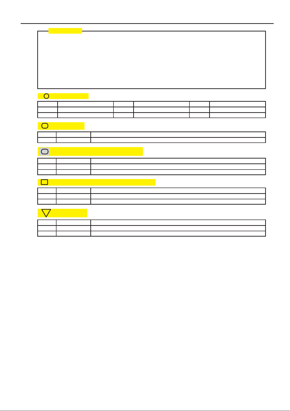
: Parts Location
Code See Page Code See Page Code See Page
H4 36 H7 36 H17 38
H6 36 H9 38 J7 38
: Relay Blocks
Code See Page Relay Blocks (Relay Block Location)
1 18 R/B No.1 (Instrument Panel Brace LH)
: Junction Block and Wire Harness Connector
Code See Page Junction Block and Wire Harness (Connector Location)
3C 22 Instrument Panel Wire and J/B No.3 (Instrument Panel Brace LH)
IB 20 Instrument Panel Wire and Instrument Panel J/B (Lower Finish Panel)
[S]
[T]
: Connector Joining Wire Harness and Wire Harness
Code See Page Joining Wire Harness and Wire Harness (Connector Location)
CH1 42 Engine Room Main Wire and Instrument Panel Wire (Left Kick Panel)
HJ1 50 Instrument Panel Wire and Floor Wire (Right Kick Panel)
: Ground Points
Code See Page Ground Points Location
H1 50 Under the Left Center Pillar
H2 50 Back Panel Center
6
CAMRY (EM0250U)

[O] : Explains the system outline.
[P] : Indicates reference pages showing the parts locations in the system circuit on the vehicle.
Example : Code ”H4” (Light Failure Sensor) is on page 36 of the manual.
* The first character of the code indicates the alphabetical code allocated to the wire harness, and the
second character indicates the serial number of the parts connected to the wire harness.
B
Example : H 4
[Q] : Indicates the reference page showing the position on the vehicle of Relay Block Connectors in the system circuit.
Example : Connector ”1” is described on page 18 of this manual and is installed on the left side of the instrument
panel.
[R] : Indicates the reference page showing the position on the vehicle of J/B and Wire Harness in the system circuit.
Example : Connector ”3C” connects the Instrument Panel Wire and J/B No.3. It is described on page 22 of this
manual, and is installed on the instrument panel left side.
[S] : Indicates the reference page describing the wiring harness and wiring harness connector (the female wiring
harness is shown first, followed by the male wiring harness).
Example : Connector ”CH1” connects the Engine Room Main Wire (female) and Instrument Panel Wire (male).
It is described on page 42 of this manual, and is installed on the left side kick panel.
[T] : Indicates the reference page showing the position of the ground points on the vehicle.
Example : Ground point ”H2” is described on page 50 of this manual and is installed on the back panel center.
Serial number for the connected parts
Code for the wire harness
CAMRY (EM0250U)
7
B HOW TO USE THIS MANUAL
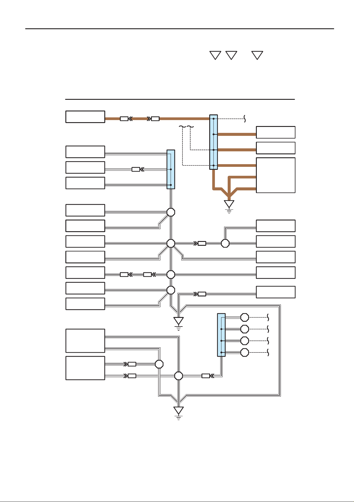
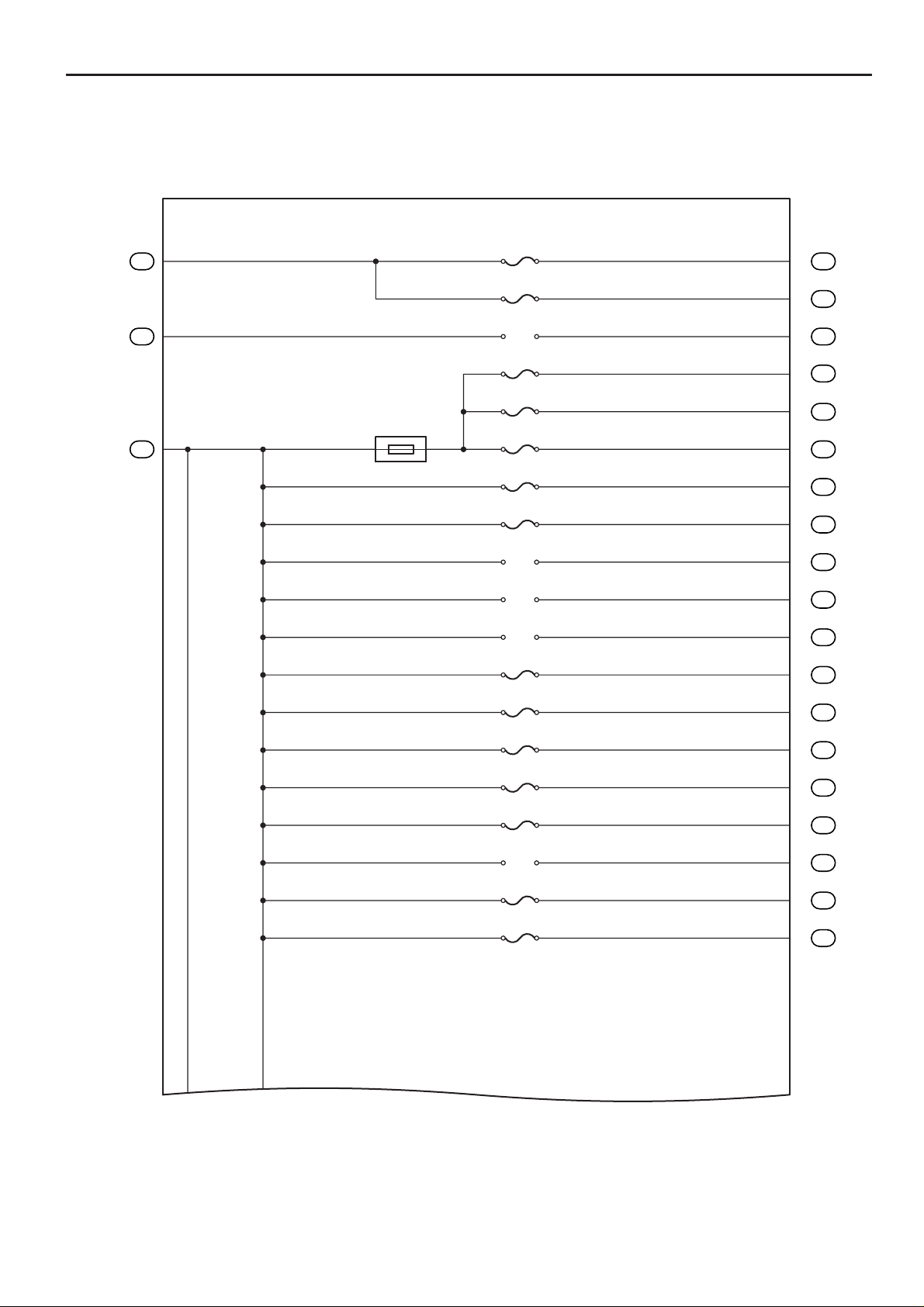
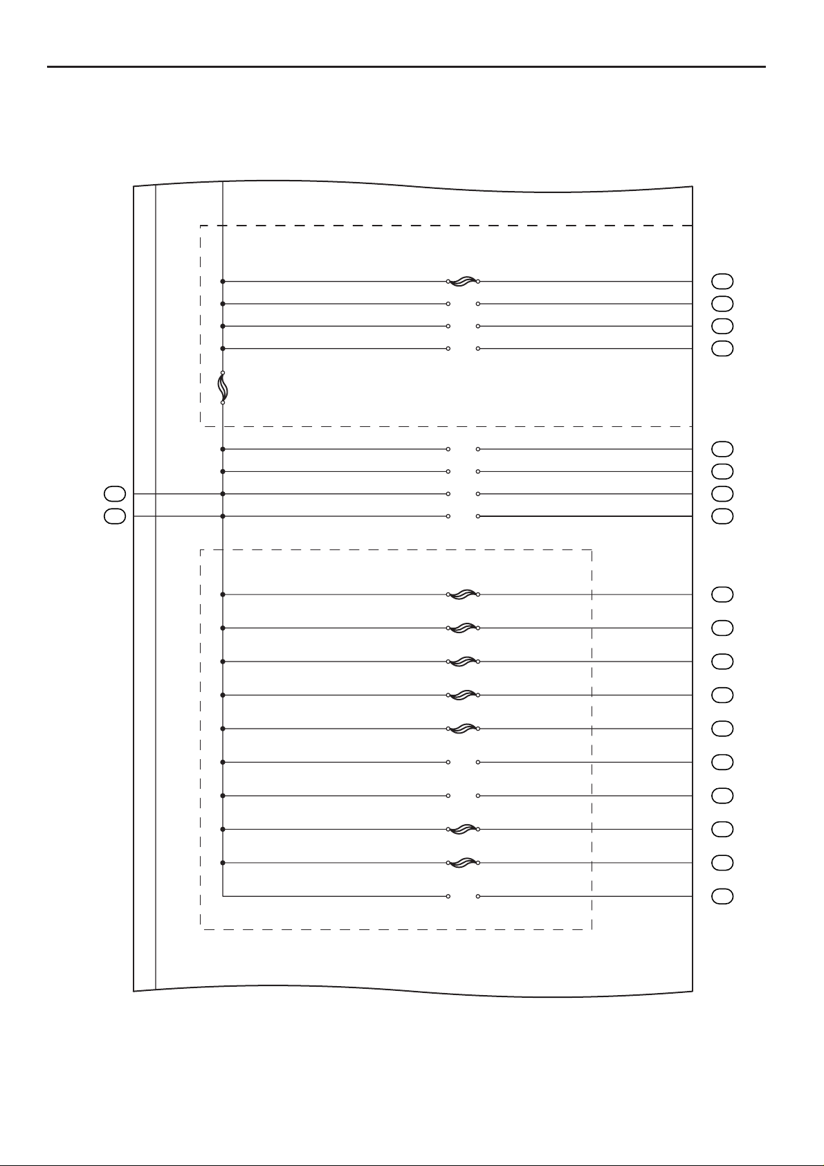
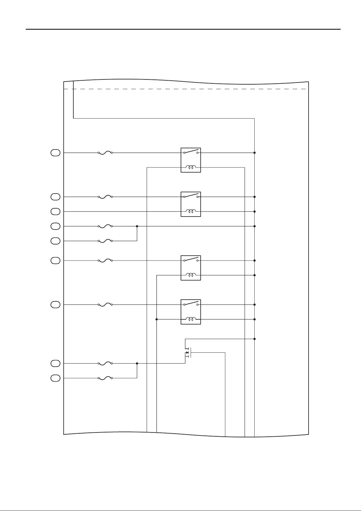
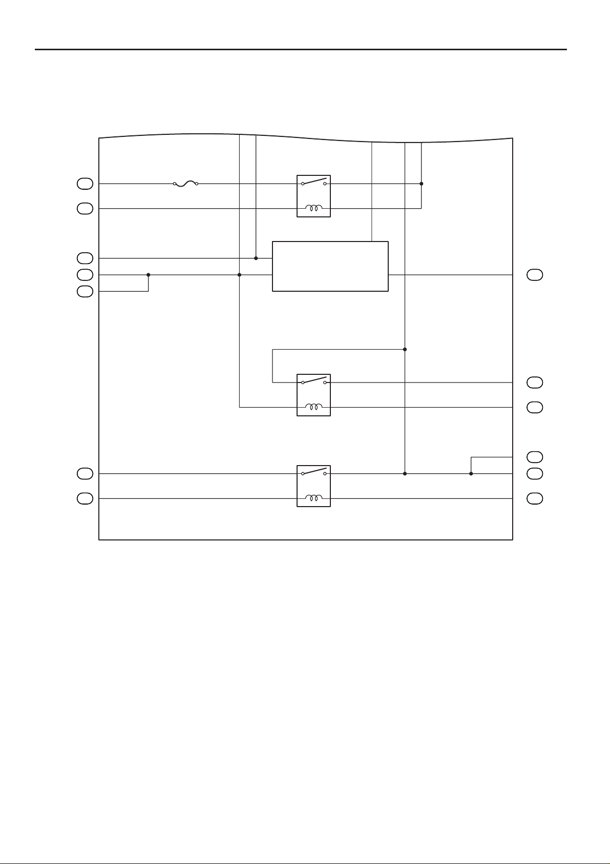
The ground points circuit diagram shows the connections from all major parts to the respective ground points. When
troubleshooting a faulty ground point, checking the system circuits which use a common ground may help you identify
A1
the problem ground quickly. The relationship between ground points (
checked this way.
I GROUND POINT
H23
DLC3
(SG)
HB4
DB1
912
10
D43
Junction
Connector
A2
,
6
(Shielded)BRBRBR
and
D4
shown below) can also be
A20
Headlamp Leveling
Motor (LH)
L5
Power Window
Master SW
A22
Cooling Fan
Motor No.3
A8
Headlamp Leveling
Motor (RH)
A5
Pressure SW
A23
Turn Signal Lamp
(Front LH)
A11
Windshield
Wiper Motor
I9
Headlamp
Leveling SW
A6
Clearance Lamp
(Front RH)
A21
Clearance Lamp
(Front LH)
A24
Option Connector
(Vacuum)
B19
Skid Control ECU
with Actuator
(LH E)
(RH E)
(–S)
(GND2)
(GND1)
(GND)
(GND)
5
(Shielded)
(Shielded)
W – B
W – B
(E)
W – B
(E)
W – B
W – B
W – B
(E)
W – B
(E)
(E)
W – B
(E)
W – B
(E)
W – B
W – B
W – B
3
LA1
12 7
IH2
21
W – BW – B
AB1
12
W – B
AB1
HA1
W – B
8
7
4
A25
Junction
Connector
3
W – B W – BW – B
W – B
CA1
W – BW – BW – B
W – B W – B
W – B W – B
A1
W – BW – B
KA1
W – B
W – B
34
2
11
1
BR
5
W – B
3
Junction
Connector
B36
16
W – B
6
AB1
BR
BR
BR
BR
BR
(5L–E)
D4
W – B
W – B
W – B
W – B
W – B
20
W – B
19
W – B
18
W – B
17
(L)
(E1)
(E1)
(E01)
(E02)
(E)
(E)
(E)
(E)
(E)
(Shielded)
(Shielded)
(Shielded)
(Shielded)
D63
Throttle
Position SW
D60
Injection
Pump Assembly
D2
Engine ECU
C2
Fog Lamp
(Front LH)
C4
Fog Lamp
(Front RH)
A10
Brake Fluid Level
Warning SW
A1
Turn Signal Lamp
(Front RH)
K5
Power Window
Master SW
W – B
A2
W – B
* The system shown here is an EXAMPLE ONLY. It is different to the actual circuit shown in the SYSTEM CIRCUITS SECTION.
8
CAMRY (EM0250U)
B
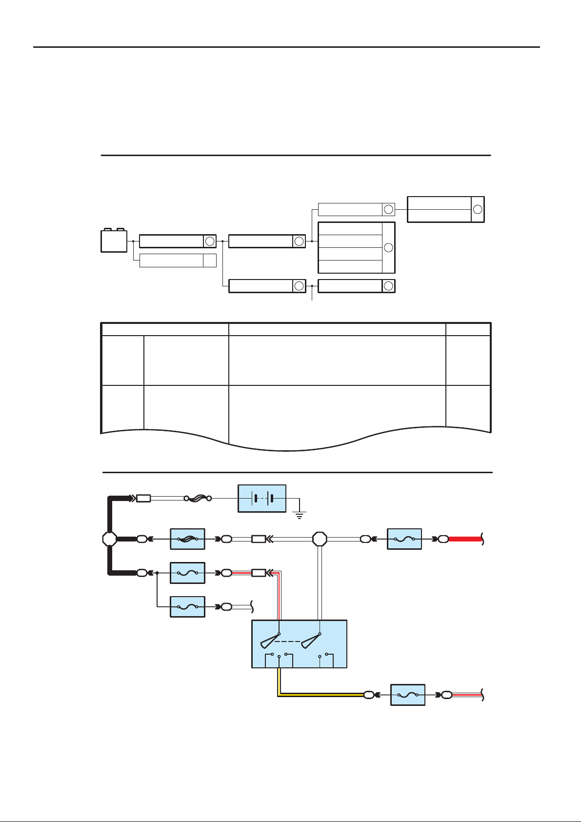
The ”Current Flow Chart” section, describes which parts each power source (fuses, fusible links, and circuit breakers)
transmits current to. In the Power Source circuit diagram, the conditions when battery power is supplied to each system
are explained. Since all System Circuit diagrams start from the power source, the power source system must be fully
understood.
J POWER SOURCE (Current Flow Chart)
The chart below shows the route by which current flows from the battery to each electrical source
(Fusible Link, Circuit Breaker, Fues, etc.) and other parts
Battery
30A AM2
Starter
2
S 2
Fusible Link Block
100A AL T
Engine Room R/B (See Page 20)
System
ABS
ABS and Traction Control
Cruise Control
Electronically Controlled Transmission
Multiplex Communication System
Cigarette Lighter
Combination Meter
Headlight
Interior Light
Key Reminder and Seat Belt Warning
Light Auto Turn Off System
Theft Deterrent and Door Lock Control
20A
10A
Fuse
STOP
DOME
Power Source
6
6
Short Pin
15A EFI
10A HAZARD
20A RADIO NO.1
10A HORN
60A ABS
10A ECU–B
2
7.5A DOME
2
5
2
Page
194
187
180
166
210
214
230
112
122
1
B
BA1
B
2
B
2
1.25B
FL MAIN
W
50A MAIN
7.5A AM1
15A HAZ–RADIO
1
Battery
W – R
W
AH1
AH1
7
6
21
2
21
2
2
2
ACC
W – R
8
AM1
IG1
2
WW
ST1
W
W
4
AM2
H8
Ignition SW
IG2
ST2
B – Y
7.5A DOME
1
1
20A DEFOG
121W – R
1
2
R
1
∗ The system shown here is an EXAMPLE ONLY. It is different to the actual circuit shown in the SYSTEM CIRCUITS SECTION.
9
CAMRY (EM0250U)
B HOW TO USE THIS MANUAL
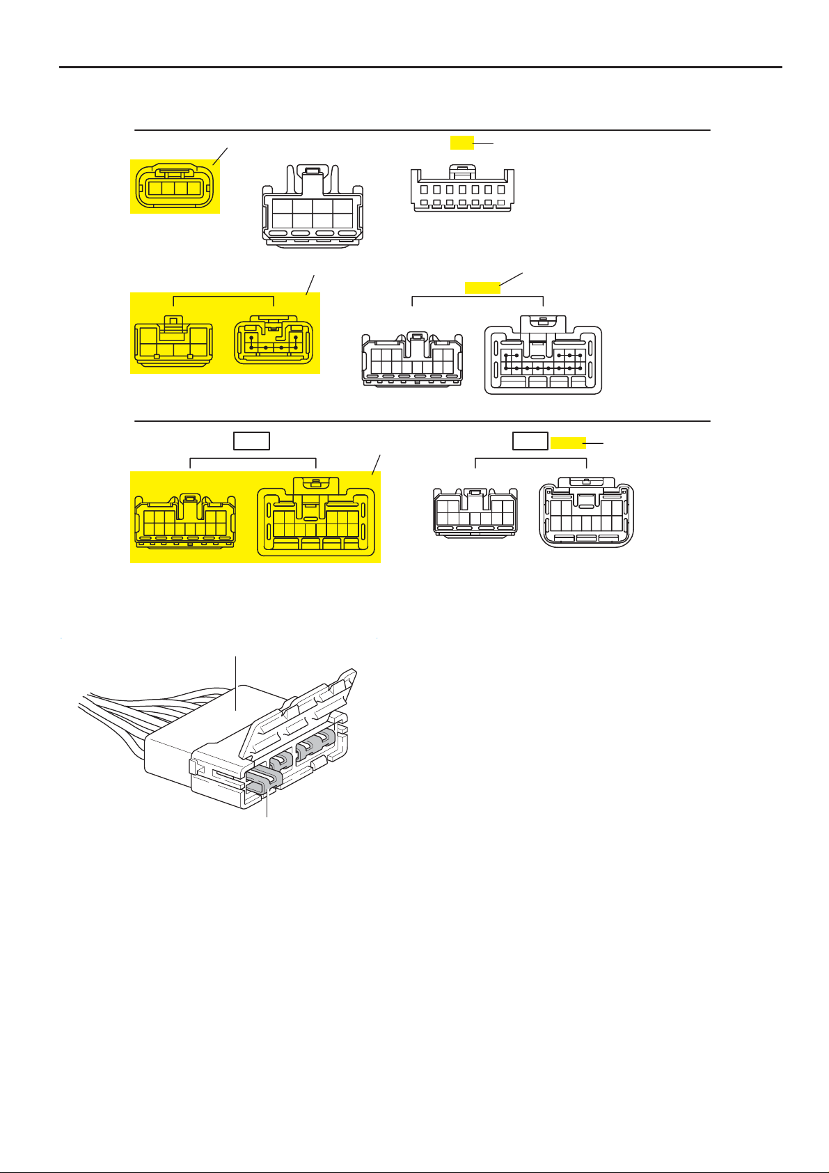
K CONNECTOR LIST
A1
Black
[A]
A2
A3
Gray
[C]
1234
B1
Black
12
3456
1234
5678
[B]
123 45
678910111213
12345 76
B2
Gray
[D]
K CONNECTOR LIST
Black
123 45
6 7 8 9 10 11 12 13
BA1
13 6789101112
[E]
12345
12 34
567891011
[A] : Indicates connector to be connected to a part. (The numeral indicates the pin No.)
BD2
Gray
43 21
11
[F]
5678910
[B] : Junction Connector
Indicates a connector which is connected to a short terminal.
Junction Connector
Junction connector in this manual include a short terminal which is
connected to a number of wire harnesses. Always perform
inspection with the short terminal installed.
Short Terminal
[C] : Parts Code
The first letter of the code is taken from the first letter of part, and the numbers indicates its order in parts which
start with the same letter.
[D] : Connector Color
Connectors not indicated are milky white in color.
[E] : Indicates the connector shapes which are used to join wire harnesses.
On Left : Female connector shapes
On Right : Male connector shapes
Numbers indicate pin numbers.
[F] : Indicates connector colors. (Connectors with not indicated colors are white)
10
CAMRY (EM0250U)
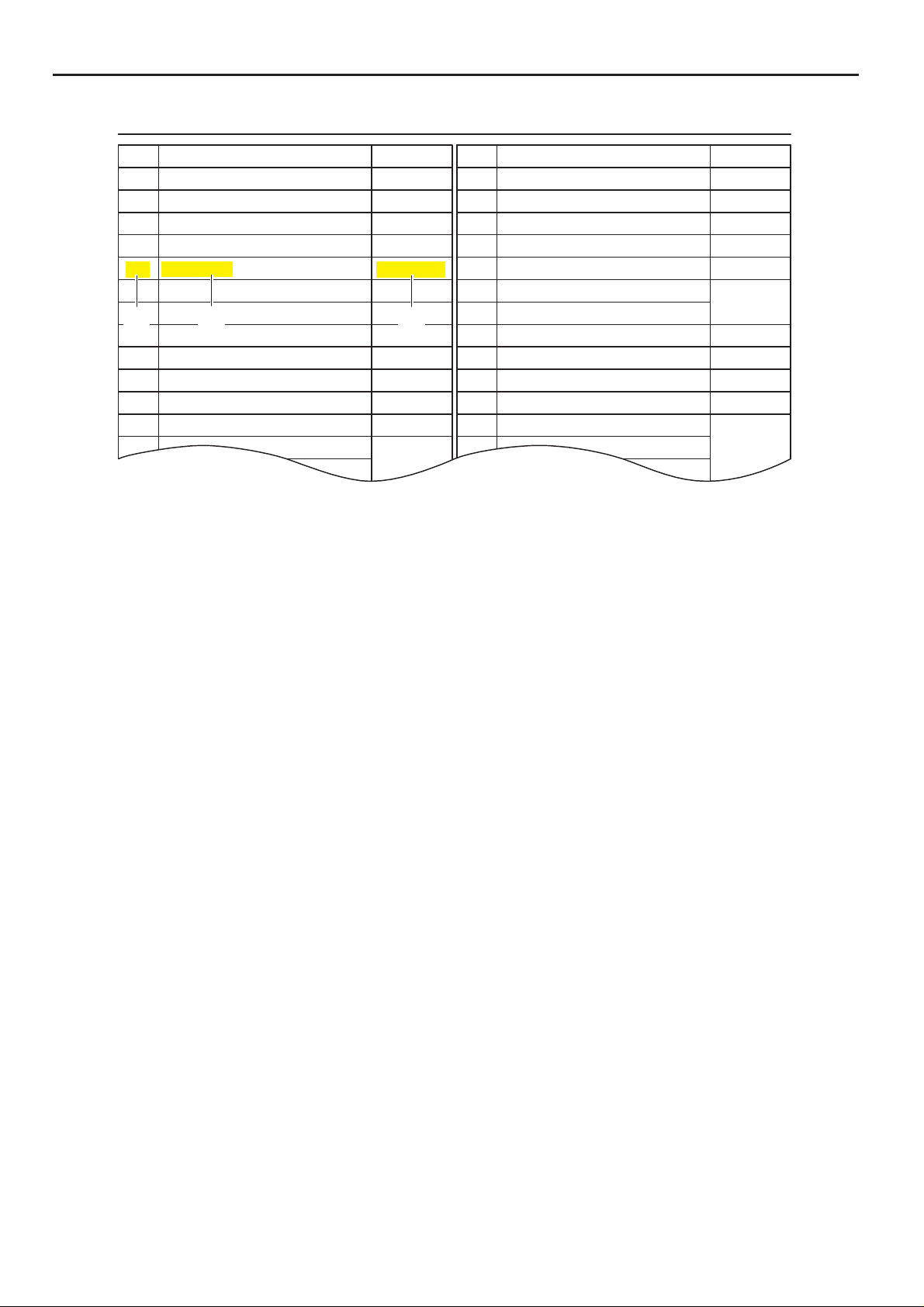
L PART NUMBER OF CONNECTORS
B
Code
A1
Turn Signal Lamp (Front RH)
A2 Inlet Air Temp. Sensor 90980–1 1163 B23 Front Seat Outer Belt (LH) 90980–12253
A3 Air Flow Meter 90980–12292 B24 Blower SW (Rear Heater) 90980–10463
A4 A/C Pressure Sensor 90980–10845
A5 Pressure SW
A6 Clearance Lamp (Front RH)
A7 Headlamp (RH)
[A]
A9 Brake Vacuum Warning SW
A10
A11
A12
A13 Airbag Squib
[B]
Brake Fluid Level Warning SW
Airbag Sensor (Front RH) Junction Connector
[A] : Part Code
[B] : Part Name
[C] : Part Number
Toyota Part Number are indicated.
Part Number
90980–11019
90980–10943
90980–11156
90980–11314
[C]
90980–11016
90980–11252
90980–11207
90980–11599
90980–11856
90980–12490
Code
B22 Door Courtesy SW (Front LH)
B25 Front Seat Outer Belt (RH) 90980–12253
B26 Door Courtesy SW (Front RH) 90980–12470
B27
Cooling Fan ECU No.1
B28
Cooling Fan ECU No.2
B29
Water Temp. Sensor (Radiator)
B30
Fuel Filter Warning SW
B32
Door Control Relay (LH)
B33
B34
B35
Junction Connector 90980–1 1398
Part NumberPart NamePart Name
90980–12470
90980–10841
90980–10735A8 Headlamp Leveling Motor (RH)
90980–11003
90980–10789
90980–10121Windshield Washer Motor Step Lamp (LH)
Not all of the above part numbers of the connector are established for the supply.
CAMRY (EM0250U)
11
C TROUBLESHOOTING
SW 2
To Ignition SW
IG Terminal
Fuse
[A]
[B]
Relay
[C]
Solenoid
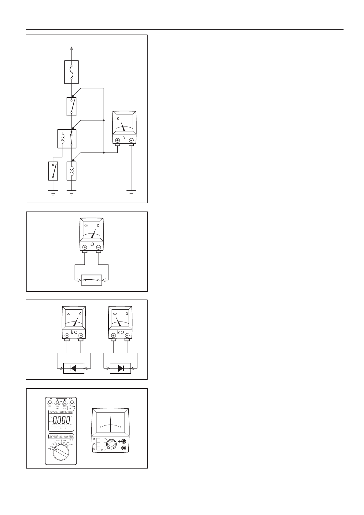
VOLTAGE CHECK
(a) Establish conditions in which voltage is present at the check
point.
Example:
[A] – Ignition SW on
[B] – Ignition SW and SW 1 on
[C] – Ignition SW, SW 1 and Relay on (SW 2 off)
(b) Using a voltmeter, connect the negative lead to a good ground
VoltmeterSW 1
point or negative battery terminal, and the positive lead to the
connector or component terminal.
This check can be done with a test light instead of a voltmeter.
CONTINUITY AND RESISTANCE CHECK
Ohmmeter
SW
Ohmmeter
Diode
Digital Type Analog Type
(a) Disconnect the battery terminal or wire so there is no voltage
between the check points.
(b) Contact the two leads of an ohmmeter to each of the check
points.
If the circuit has diodes, reverse the two leads and check
again.
When contacting the negative lead to the diode positive side
and the positive lead to the negative side, there should be
continuity.
When contacting the two leads in reverse, there should be no
continuity.
(c) Use a volt/ohmmeter with high impedance (10 kΩ/V
minimum) for troubleshooting of the electrical circuit.
12
CAMRY (EM0250U)
C
Test Light
Disconnect
To Ignition SW
IG Terminal
Fuse Case
Short [A]
SW 1
Short [B]
Disconnect
RelayLight
Short [C]
Disconnect
SW 2 Solenoid
FINDING A SHORT CIRCUIT
(a) Remove the blown fuse and disconnect all loads of the fuse.
(b) Connect a test light in place of the fuse.
(c) Establish conditions in which the test light comes on.
Example:
[A] – Ignition SW on
[B] – Ignition SW and SW 1 on
[C] – Ignition SW, SW 1 and Relay on (Connect the
Relay) and SW 2 off (or Disconnect SW 2)
(d) Disconnect and reconnect the connectors while watching the
test light.
The short lies between the connector where the test light
stays lit and the connector where the light goes out.
(e) Find the exact location of the short by lightly shaking the
problem wire along the body.
CAUTION:
(a) Do not open the cover or the case of the ECU unless
absolutely necessary. (If the IC terminals are touched,
the IC may be destroyed by static electricity.)
(b) When replacing the internal mechanism (ECU part) of
the digital meter, be careful that no part of your body or
clothing comes in contact with the terminals of leads
from the IC, etc. of the replacement part (spare part).
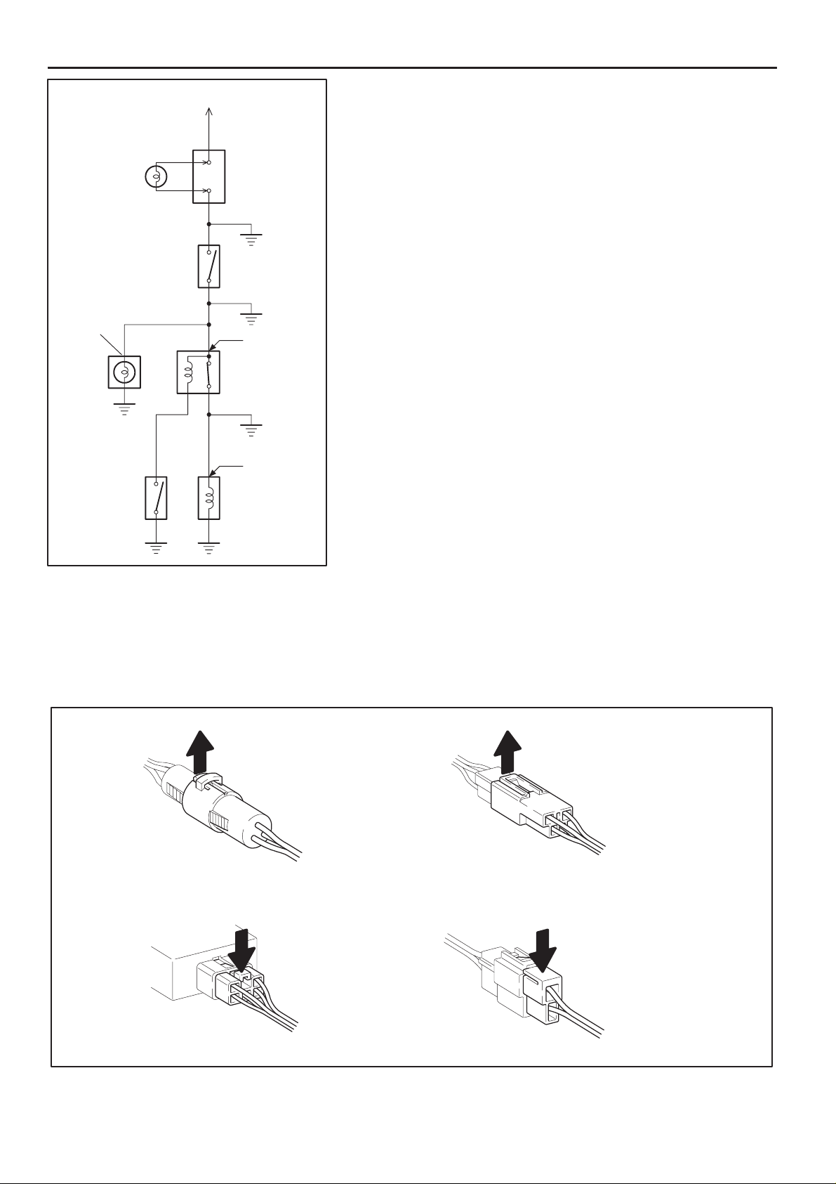
DISCONNECTION OF MALE AND FEMALE
CONNECTORS
To pull apart the connectors, pull on the connector itself, not
the wire harness.
HINT : Check to see what kind of connector you are
disconnecting before pulling apart.
Pull Up
Press Down Press Down
Pull Up
CAMRY (EM0250U)
13
C TROUBLESHOOTING
Reference:
10
1
Example:
(Case 1)
Terminal Retainer
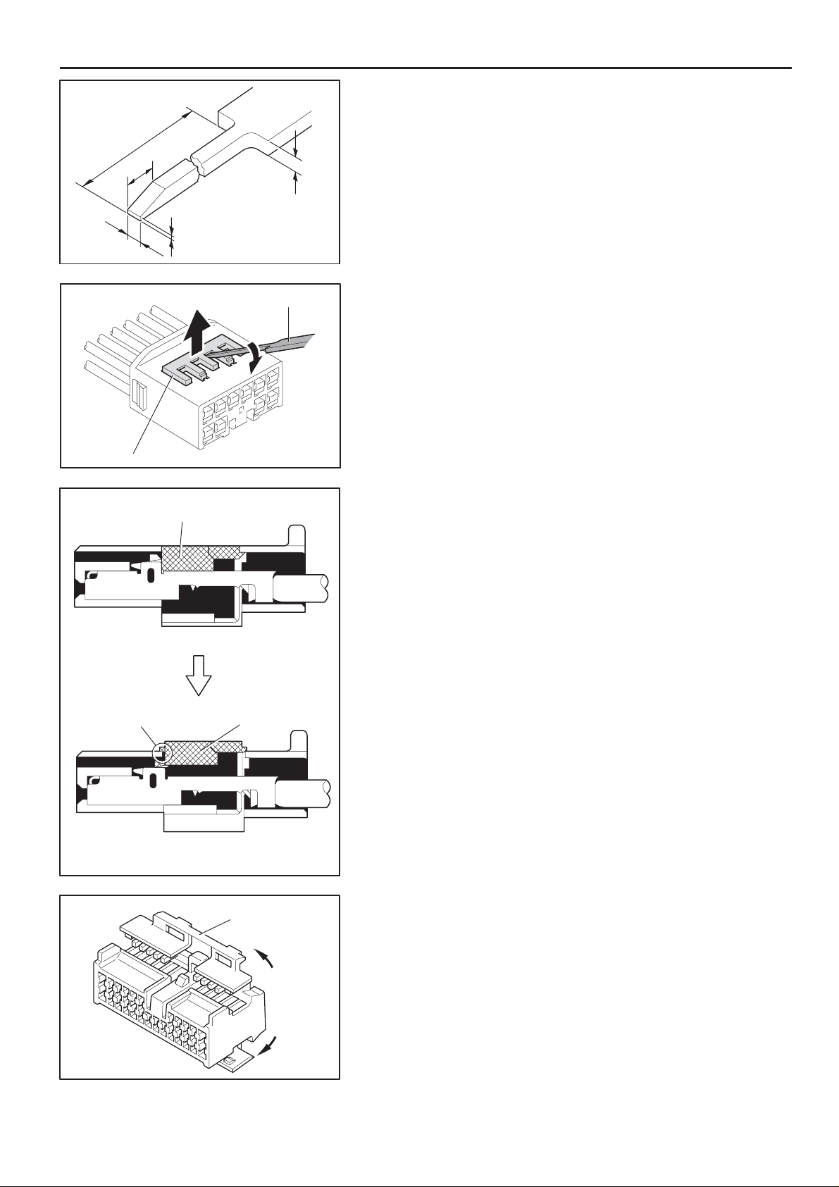
HOW TO REPLACE TERMINAL
(with terminal retainer or secondary locking device)
1. PREPARE THE SPECIAL TOOL
3
0.2
Up
Tool
1
(mm)
HINT : To remov e the te rmin al from th e connector, please
construct and use the special tool or like object shown on
the left.
2. DISCONNECT CONNECT OR
3. DISENGAGE THE SECONDARY LOCKING DEVICE OR
TERMINAL RETAINER.
(a) Locking device must be disengaged before the terminal
locking clip can be released and the terminal removed from
the connector.
(b) Use a special tool or the terminal pick to unlock the secondary
locking device or terminal retainer.
NOTICE:
Do not remove the terminal retainer from connector body.
Terminal Retainer
[Retainer at Full Lock Position]
Stopper
[Retainer at Temporary Lock Position]
Example:
(Case 2)
Terminal
Retainer
Secondary
Locking Device
[A] For Non–Waterproof Type Connector
HINT : The needle insertion position varies according to the
connector’s shape (number of terminals etc.), so
check the position before inserting it.
”Case 1”
Raise the terminal retainer up to the temporary lock
position.
”Case 2”
Open the secondary locking device.
14
CAMRY (EM0250U)
Tab
Tab
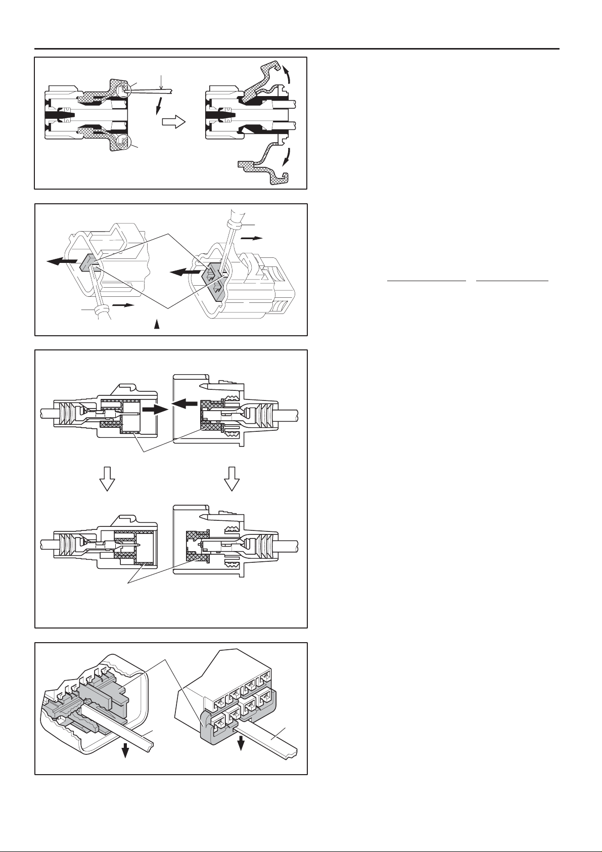
C
Tool
Example:
(Case 1)
Tool
[Male]
Terminal
Retainer
Access Hole
( Mark)
Retainer
at Full Lock Position
[Female]
Tool
[B] For Waterproof Type Connector
HINT : Terminal r etainer co lor is different
according to connector body.
Example:
Terminal Retainer
: Connector Body
Black or White : Gray
Black or White : Dark Gray
Gray or White : Black
”Case 1”
Type where terminal retainer is pulled
up to the temporary lock position (Pull
Type).
Insert the special tool into the terminal
retainer access hole (YMark) and pull
the terminal retainer up to the
temporary lock position.
HINT : The needle insertion position varies
according to the connector’s shape
(Number of terminals etc.), so check
the position before inserting it.
Example:
(Case 2)
[Male]
Retainer
at Temporary Lock Position
[Male] [Female]
Terminal Retainer
Tool
Press Down
Press Down
[Female]
CAMRY (EM0250U)
”Case 2”
Type which cannot be pulled as far as
Power Lock insert the tool straight into
the access hole of terminal retainer as
shown.
Tool
15
C TROUBLESHOOTING
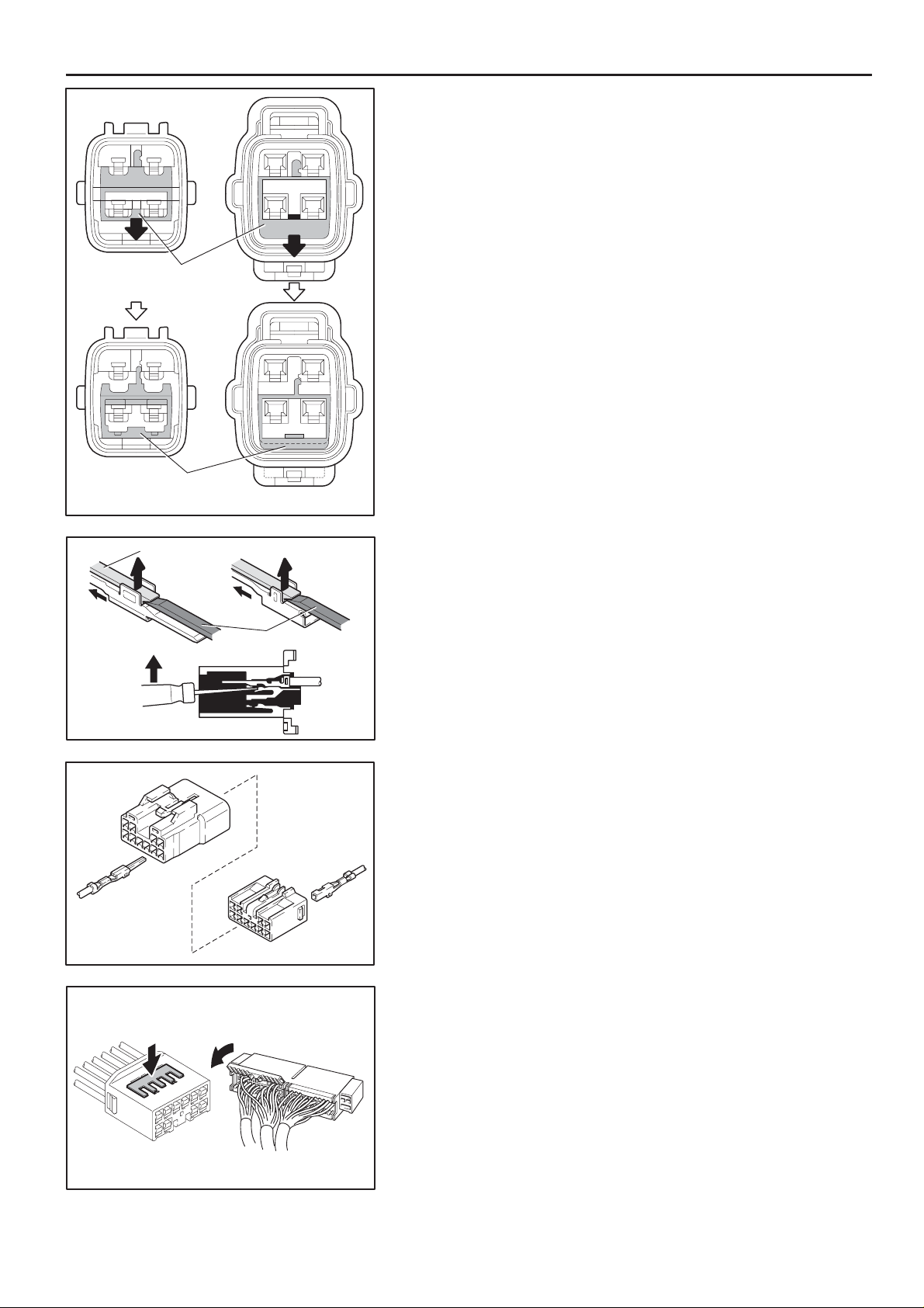
Retainer at
Full Lock Position
Retainer at
Temporary Lock Position
[Male] [Female]
Push the terminal retainer down to the temporary lock position.
Locking Lug
(c) Release the locking lug from terminal and pull the terminal out
from rear.
Tool
4. INSTALL TERMINAL TO CONNECTOR
(a) Insert the terminal.
HINT:
1. Make sure the terminal is positioned correctly.
2. Insert the terminal until the locking lug locks firmly.
3. Insert the terminal with terminal retainer in the temporary lock
position.
16
(b) Push the secondary locking device or terminal retainer in to
the full lock position.
5. CONNECT CONNECT OR
CAMRY (EM0250U)

ABBREVIATIONS D
ABBREVIATIONS
The following abbreviations are used in this manual.
A/C = Air Conditioning
A/T = Automatic Transaxle
ABS = Anti–Lock Brake System
ACIS = Acoustic Control Induction System
ACM = Active Control Engine Mount
CAN = Controller Area Network
EC = Electrochromic
ECU = Electronic Control Unit
ESA = Electronic Spark Advance
ETCS–i = Electronic Throttle Control System–intelligent
FL = Fusible Link
IC = Integrated Circuit
J/B = Junction Block
LCD = Liquid Crystal Display
LH = Left–Hand
M/T = Manual Transaxle
R/B = Relay Block
RH = Right–Hand
SFI = Sequential Multiport Fuel Injection
SRS = Supplemental Restraint System
SW = Switch
TEMP. = Temperature
TRAC = Traction Control
VSC = Vehicle Stability Control
VSV = Vacuum Switching Valve
VVT = Variable Valve Timing
VVT–i = Variable Valve Timing–intelligent
w/ = With
w/o = Without
∗ The titles given inside the components are the names of the terminals (terminal codes) and are not treated as being
abbreviations.
CAMRY (EM0250U)
17
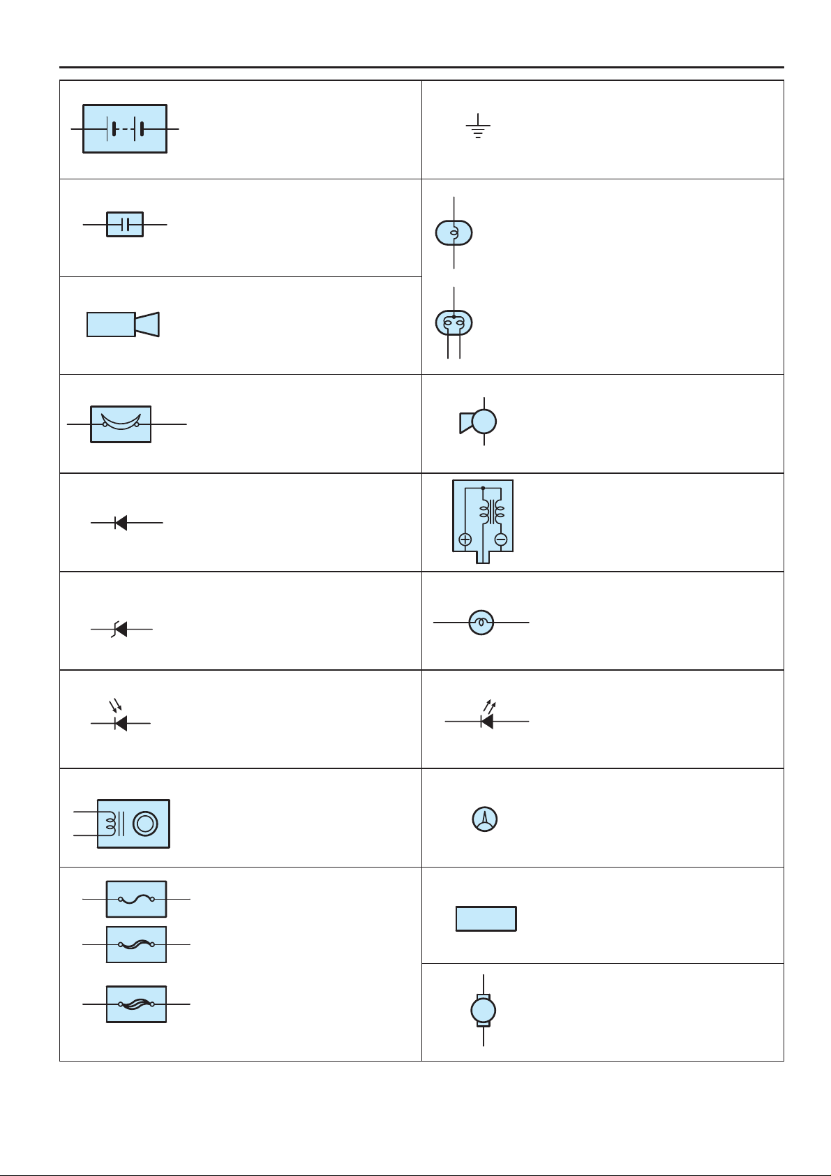
E GLOSSARY OF TERMS AND SYMBOLS
FUSIBLE LINK
FUSIBLE LINK
BATTERY
Stores chemical energy and
converts it into electrical energy .
Provides DC current for the auto’s
various electrical circuits.
CAPACITOR (Condenser)
A small holding unit for temporary
storage of electrical voltage.
CIGARETTE LIGHTER
An electric resistance heating
element.
CIRCUIT BREAKER
Basically a reusable fuse, a circuit
breaker will heat and open if too
much current flows through it.
Some units automatically reset when
cool, others must be manually reset.
DIODE
A semiconductor which allows
current flow in only one direction.
1. SINGLE
FILAMENT
2. DOUBLE
FILAMENT
GROUND
The point at which wiring attaches to
the Body , thereby providing a return
path for an electrical circuit; without a
ground, current cannot flow.
HEADLIGHTS
Current flow causes a headlight
filament to heat up and emit light. A
headlight may have either a single
(1) filament or a double (2) filament
HORN
An electric device which sounds a
loud audible signal.
IGNITION COIL
Converts low–voltage DC current
into high–voltage ignition current for
firing the spark plugs.
(for Medium Current Fuse)
(for High Current Fuse or
Fusible Link)
DIODE, ZENER
A diode which allows current flow in one
direction but blocks reverse flow only up
to a specific voltage. Above that potential,
it passes the excess voltage. This acts as
a simple voltage regulator.
PHOTODIODE
The photodiode is a semiconductor
which controls the current flow
according to the amount of light.
DISTRIBUTOR, IIA
Channels high–voltage current from
the ignition coil to the individual
spark plugs.
FUSE
A thin metal strip which burns through
when too much current flows through it,
thereby stopping current flow and
protecting a circuit from damage.
A heavy–gauge wire placed in high
amperage circuits which burns through on
overloads, thereby protecting the circuit.
The numbers indicate the crosssection
surface area of the wires.
FUEL
M
LIGHT
Current flow through a filament
causes the filament to heat up and
emit light.
LED (LIGHT EMITTING DIODE)
Upon current flow, these diodes emit
light without producing the heat of a
comparable light.
METER, ANALOG
Current flow activates a magnetic
coil which causes a needle to move,
thereby providing a relative display
against a background calibration.
METER, DIGITAL
Current flow activates one or many
LED’s, LCD’s, or fluorescent
displays, which provide a relative or
digital display .
MOTOR
A power unit which converts
electrical energy into mechanical
energy , especially rotary motion.
18
CAMRY (EM0250U)
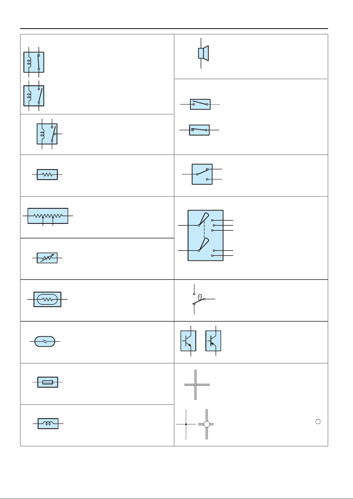
E
Opens and closes
operational.
black dot at the junction are
black dot at the junction are
RELAY
1. NORMALLY
CLOSED
2. NORMALLY
OPEN
RELAY, DOUBLE THROW
RESISTOR
RESISTOR, TAPPED
RESISTOR, VARIABLE or RHEOSTAT
Basically, an electrically operated
switch which may be normally
closed (1) or open (2).
Current flow through a small coil
creates a magnetic field which either
opens or closes an attached switch.
A relay which passes current
through one set of contacts or the
other.
An electrical component with a fixed
resistance, placed in a circuit to
reduce voltage to a specific value.
A resistor which supplies two or
more different non adjustable
resistance values.
A controllable resistor with a variable
rate of resistance.
Also called a potentiometer or
rheostat.
SPEAKER
An electromechanical device which
creates sound waves from current
flow.
SWITCH, MANUAL
Opens and closes
1. NORMALLY
OPEN
2. NORMALLY
CLOSED
SWITCH, DOUBLE THROW
A switch which continuously passes
current through one set of contacts
or the other.
SWITCH, IGNITION
A key operated switch with several
positions which allows various
circuits, particularly the primary
ignition circuit, to become
operational.
circuits, thereby
stopping (1) or
allowing (2) current
flow.
(Reed Switch Type)
SENSOR (Thermistor)
A resistor which varies its resistance
with temperature.
SENSOR, SPEED
Uses magnetic impulses to open
and close a switch to create a signal
for activation of other components.
SHORT PIN
Used to provide an unbroken
connection within a junction block.
SOLENOID
An electromagnetic coil which forms
a magnetic field when current flows,
to move a plunger, etc.
SWITCH, WIPER PARK
Automatically returns wipers to the
stop position when the wiper switch
is turned off.
TRANSISTOR
A solidstate device typically used as
an electronic relay; stops or passes
current depending on the voltage
applied at ”base”.
WIRES
(1) NOT
CONNECTED
(2) SPLICED
Wires are always drawn as
straight lines on wiring
diagrams.
Crossed wires (1) without a
not joined;
crossed wires (2) with a
black dot or octagonal ( )
mark at the junction are
spliced (joined)
connections.
19
CAMRY (EM0250U)
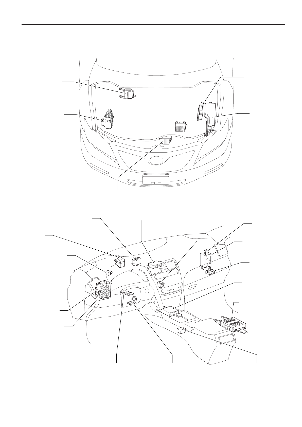
F RELAY LOCATIONS
)
r
t
r
M
T
I
J
[Engine Compartment]
Engine Control
Module(2GR-FE)
Skid Control ECU
with Actuator
[Instrument Panel]
ID Code Box (*1)
Transponder Key ECU (*2)
Cooling Fan ECU
Junction Connector (CAN) J/B No.4
Transmission Control ECU
Engine Control
Module(2AZ-FE
Engine Room
R/B
Engine Room
J/B
A/C Amplifie
J/B No.3
urn Signal Flasher
ain Body ECU
nstrument Panel
/B
* 1:w/ Smart System
* 2:w/o Smart System
Steering Lock ECU Transponder Key Amplifier
Certification ECU
Tire Pressure
Warning ECU
Airbag Sensor
Assembly Cente
Stereo Componen
Amplifier
Shift Lock Control ECU
20
CAMRY (EM0250U)
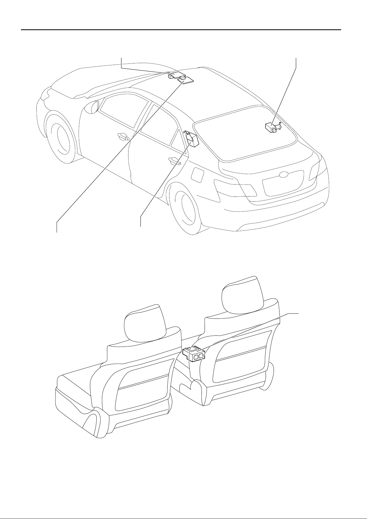
[Body]
F
Sliding Roof Control ECU and Motor Door Control Receiver
Overhead J/B
[Seat]
Tire Pressure Warning
Antenna and Receiver
Occupant
Classification
ECU
CAMRY (EM0250U)
21
F RELAY LOCATIONS
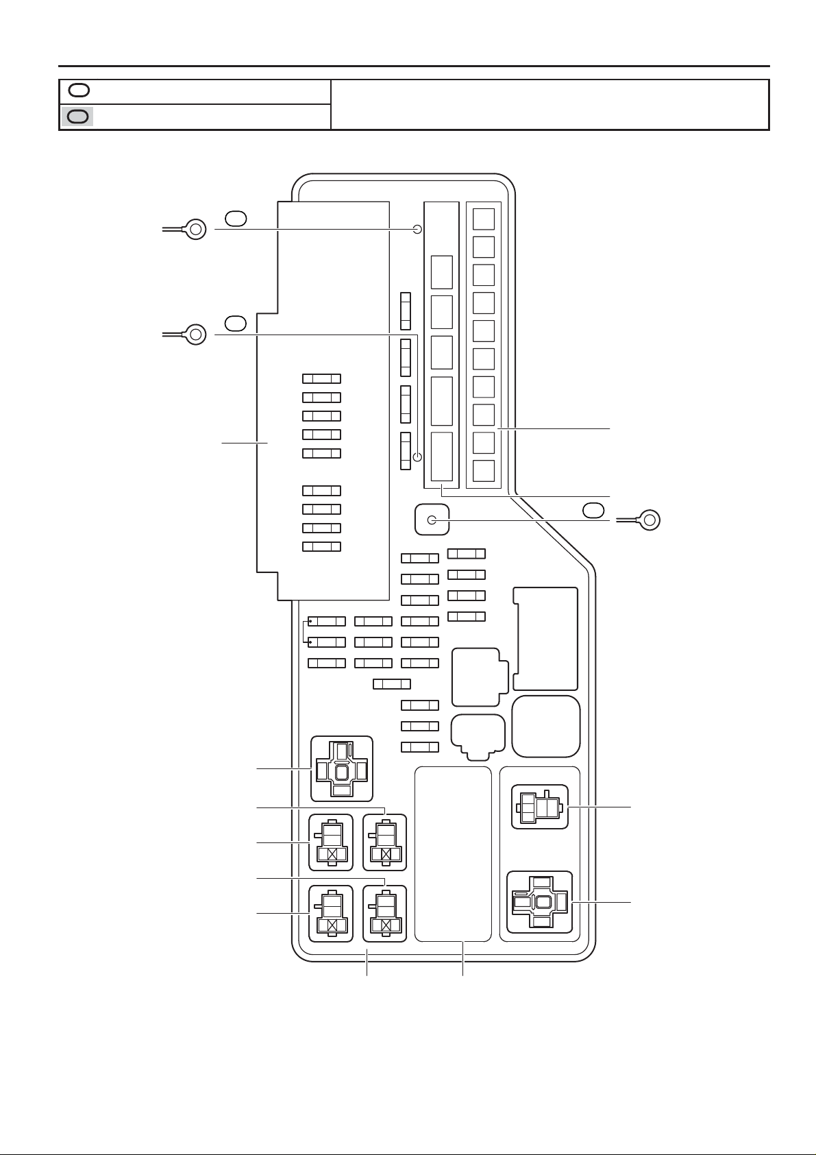
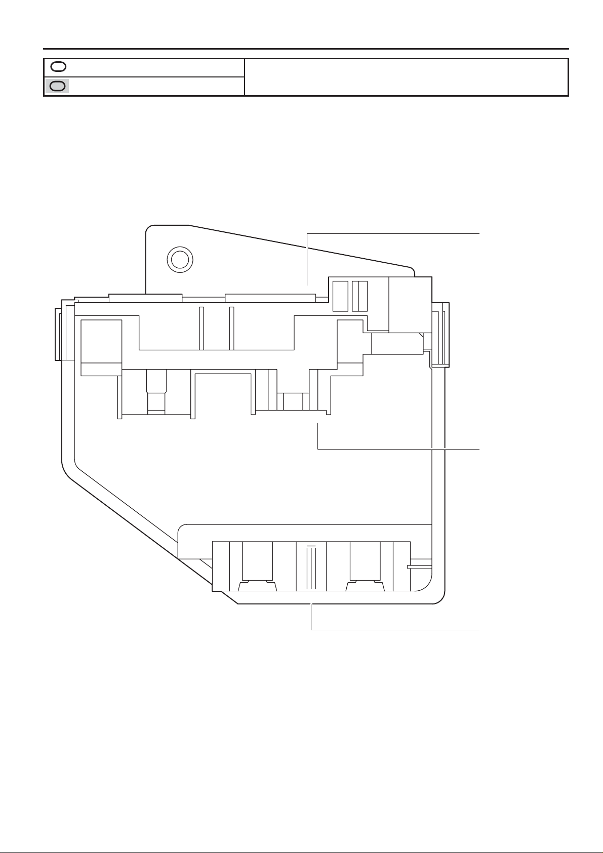
Engine Compartment Left (See Page 20)
1
: Engine Room R/B
: Engine Room J/B
1G
1
(from Engine Room Main Wire)
Wire Color : W
1F
1
(from Engine Room Main Wire)
Wire Color : B
Unit D
H-LP (LH)
15A
H-LP (RH)
15A
H-LP (LL)
15A
H-LP (RL)
15A
HORN
10A
EFI NO.1
10A
MPX-B
10A
A/F
20A
S-HORN
7.5A
EFI NO.2
15A
EFI NO.3
10A
RADIO NO.1
21
ECU-B NO.1
21
DOME
15A
10A
10A
12
12
SHORT
2
30A
1
EFI MAIN
2
25A
AMP
1
2
25A
1
DOOR NO.1
STR LOCK
20A
21
IG2
20A
21
HAZ
15A
1
2
ETCS
1
212
10A
12
* 1:120A ALT (for High Current)
* 2:30A ST/AM2 (for High Current)
* 3:50A HTR (for High Current)
* 4:50A ABS No.1 (for High Current)
* 5:50A FAN MAIN (for High Current)
* 6:30A ABS No.2 (for High Current)
* 7:50A RR DEF (for High Current)
* 8:40A CDS FAN (for High Current)
*9
*2
*8
*7
*6
*5
* 9:40A RDI FAN (for High Current)
Unit B
*4
*1
*3
Unit A
1C
(from Engine Wire)
Wire Color : B
1
22
RR DEF Relay
IG2 Relay
ST CUT Relay
ST Relay
MGC Relay
3
12
4
5
3
5
12
3
5
12
3
5
12
3
5
12
Unit C Unit E
ALT-S
12
7.5A
AM2
12
7.5A
1
35
2
2
35
1
VSC No.1 Relay
VSC NO.2 Relay
CAMRY (EM0250U)
Unit E
F
FAN NO.1 Relay
FAN NO.3 Relay
FAN NO.2 Relay
2AZ-FE
1
2
1
2
1
4
2
2GR-FE
35
35
2
35
35
1
FAN MAIN Relay
CAMRY (EM0250U)
23
F RELAY LOCATIONS
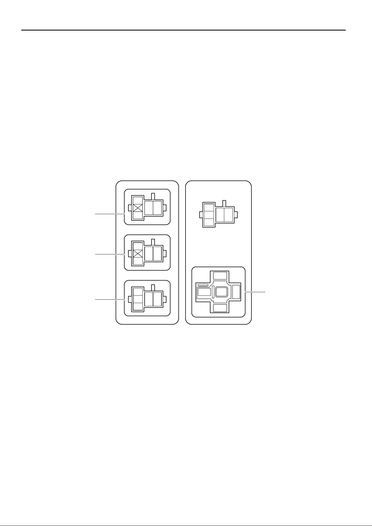
Engine Compartment Left (See Page 20)
1
: Engine Room R/B
: Engine Room J/B
Unit D
View A
View B
View C
24
CAMRY (EM0250U)
F
View A
Black
12345
123456
(from Engine Room
Main Wire)
1A
12345
(from Engine Room
Main Wire)
1B
123456
10111213
(from Engine Room
Main Wire)
6789
12345
View B
Black
678910111213
12345
(from Engine Room
Main Wire)
1D 1E
543 21
12345
6789
CAMRY (EM0250U)
1011121310111213
6987
View C
25
F RELAY LOCATIONS
[Engine Room R/B and Engine Room J/B Inner Circuit]
Unit C
1 1
1
1
15A EFI NO.2
1
10A EFI NO.3
2
2
1
1
1
15A RADIO NO.1
1
SHORT
1
1G
21
10A ECU-B NO.1
1
10A DOME
12
7.5A AM2
1
7.5A ALT-S
1
10A ETCS
1
15A HAZ
1
20A IG2
1
20A STR LOCK
1
30A EFI MAIN
2
2
2
2
2
2
2
2
2
1
1
1
1
1
1
1
1
1
1
1
1
1
1
26
12
25A AMP
21
25A DOOR NO.1
(Cont. Next Page)
CAMRY (EM0250U)
1
1
F
(Cont'd)
Unit A
30A ST/AM2
120A
ALT
1
1C
1
1F
1
1
1
1
1
1
1
1
Unit B
50A HTR
1
1
50A ABS No.1
1
50A FAN MAIN
1
30A ABS No.2
1
50A RR DEF
1
1
1
40A CDS FAN
1
40A RDI FAN
1
(Cont. Next Page)
CAMRY (EM0250U)
27
F RELAY LOCATIONS
[Engine Room R/B and Engine Room J/B Inner Circuit]
(Cont'd)
Unit D
11
4
1A
5
1A
1D
3
1A
2
1A
5
1B
4
1B
20A A/F
7.5A S-HORN
10A MPX-B
10A EFI NO.1
15A H-LP (RL)
15A H-LP (LL)
A/F Relay
S-HORN Relay
H-LP (RL) Relay
H-LP (LL) Relay
28
3
1B
2
1B
15A H-LP (RH)
15A H-LP (LH)
DRL Relay
(Cont. Next Page)
CAMRY (EM0250U)
(Cont'd)
F
10
10
11
13
6
1B
1D
9
1D
1E
1E
1E
10A HORN
HORN Relay
Light Control Circuit
EFI Relay
C/OPN Relay
12
8
1D
1E
9
1E
6
1E
7
1E
8
1E
12
1D
CAMRY (EM0250U)
29

F RELAY LOCATIONS
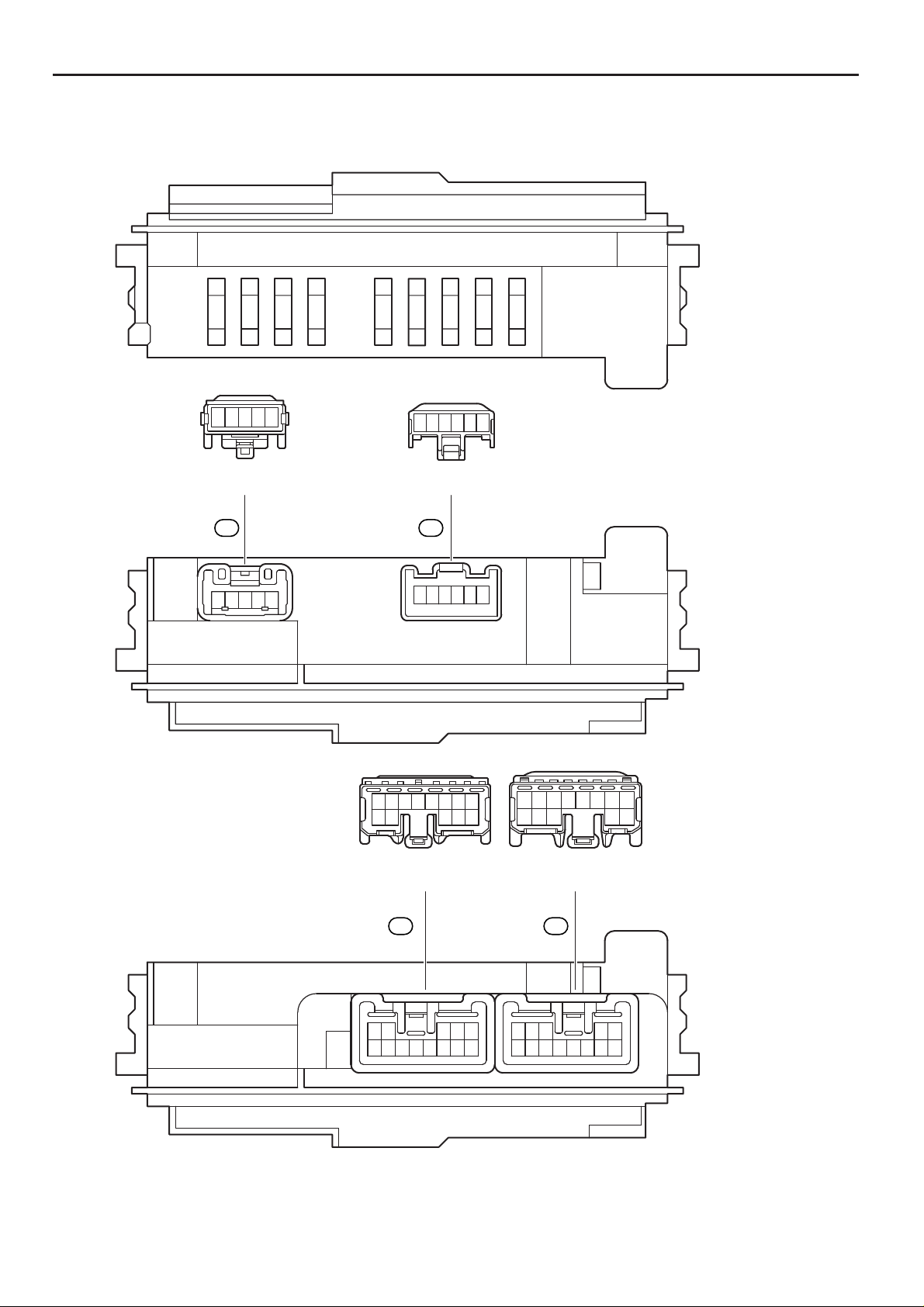
: Instrument Panel J/B Cowl Side Left (See Page 20)
20
10
111213
14
1234
56789
(from Instrument Panel Wire)
9
10
11
13
12
14
16
45678
123
(from Instrument Panel Wire)
11
12
789
123456
(from Instrument Panel Wire)
11
12
10
14
67
89
123
45
(from Engine Room Main Wire)
14
13
15
16
12
9
123
45678
(from Engine Room Main Wire)
IB
12
(from Engine Room Main Wire)
IA
1
(from Engine Room Main Wire)
FOG Relay
TAIL Relay
IM
IK
IL
IC
ID
9
10
11
321
97
3218456
8
9
11
10
321
1
2
21
5
3
13
12
14
151516
4 678
5
101011
12
12
131314
67
45
21
IJ
12
6
345
78
12
10
11
9
(from Instrument Panel Wire)
Yellow
123456
78 9
10
20
10
1
2345
7
11
89
12
11
13
15
16
13
14
12
1234
56789
6
12
10
789
123
456
1
9
1
11
111112
10
1213
2
2
1515161617171818191920
14
431
15
13
14
431
13
14
12
11
32
16
17171818191920
15
645
78
12
6
34
12
7
132
5
78
12
9
10
11
123456
789
10
IE
(from Instrument Panel Wire)
IF
1
6
2345
7
89
101011
12
10
11
8
9
13
645
(from Instrument Panel Wire)
IR
(from Instrument Panel Wire)
IO
98756
10
98756
10
16
1010111112
97
8
321
456
(from Floor Wire)
4
5
3
3
12
2
5
12
5
3
3
1
5
IP
12
(from Floor Wire)
789
10
11
123456
IG1 Relay
PWR Relay
ACC Relay
30
CAMRY (EM0250U)

F
Main Body ECU
IG
78
910101112
3456
12
(from Instrument Panel Wire)
67
89
345
12
II
(from Instrument Panel Wire)
1
2
3
4
5
6
7
8
9
10
11
12
13
14
15
16
17
18
19
20
21
22
23
24
25
26
6
8
7
9
10 101112 10101111121213
356
21
7
9
4
5384
21
IH
16
13
9
1234
5
678
(from Instrument Panel Wire)
2
1414151516
9
1
542
8376
2
1
1
30A POWER
(for High Current)
30A P/SEAT
(for High Current)
CAMRY (EM0250U)
31

F RELAY LOCATIONS
: Instrument Panel J/B Cowl Side Left (See Page 20)
25A
25A
RR DOOR LH
RR DOOR RH
10A
7.5A
A/C NO.2
ECU IG NO.1
ECU IG NO.2
10A
FR FOG
10A
WASH
15A
7.5A
OBD
20A
S-HTR
GAUGE NO.1
10A
WIP
10A
STOP
25A
INJ
15A
IGN
A/C
AM1
7.5A
7.5A
10A
7.5A
ECU-ACC
GAUGE NO.2
PWR
7.5A
25A
25A
30A
S/ROOF
DOOR NO.2
20A
RADIO NO.2
PWR OUTLET
15A
TAIL
7.5A
MIR HTR
7.5A
PANEL
10A
32
CAMRY (EM0250U)

[Instrument Panel J/B Inner Circuit]
1
IE
2
IE
10
IF
1
IR
4
5
1
TAIL Relay
5
1
FOG Relay
11
1
IA
4
IK
5
IK
6
IK
IM
4
ID
4
IL
15A FR FOG
F
4
IC
5
IC
6
ID
14
ID
11
IH
3
15A TAIL
3
7. 5A PANEL
2
3
2
IL
8
IP
6
IF
2
IO
3
IR
4
IH
1
IC
5
ID
6
IG
8
II
10
10
13
10
12
14
10
IM
11
6
IE
IH
5
IE
IG
3
IM
3
II
2
IB
IO
3
IE
3
IG
IE
3
IF
1
IH
IM
9
IJ
IK
4
IR
12
30A P/SEAT
5
2
ACC Relay
3
1
7.5A RADIO NO.2
20A PWR OUTLET
7.5A ECU-ACC
10A MIR HTR
12
10
16
12
12
11
12
IO
IF
IO
IM
IO
2
IF
8
IK
5
IH
IJ
1
IK
IL
4
IO
7
ID
8
ID
8
IG
6
II
IP
(Cont. Next Page)
CAMRY (EM0250U)
33

F RELAY LOCATIONS
[Instrument Panel J/B Inner Circuit]
(Cont'd)
14
16
12
11
11
13
13
10
10
12
12
17
2
IP
IF
IH
9
IO
4
IE
4
IF
IH
6
IM
8
IF
9
IF
1
IG
IR
IJ
IK
2
IR
9
II
ID
7
IF
IL
IP
6
IR
7
IR
3
IC
9
IC
2
IG
1
II
9
IL
IR
30A S/ROOF
IL
IM
10A GAUGE NO.1
25A PWR
5
2
IG1 Relay
5
1
PWR Relay
3
1
3
2
10A ECU IG NO.1
25A WIP
10A WASH
10A A/C NO.2
20A S-HTR
7.5A ECU IG NO.2
12
30A POWER
25A RR DOOR LH
25A RR DOOR RH
7.5A A/C
7.5A AM1
25A DOOR NO.2
7.5A OBD
10A STOP
11
10
11
12
12
16
19
20
19
10
11
18
17
6
IC
IF
3
IO
IR
2
IC
2
II
IC
IC
ID
IF
IM
IM
IF
6
IO
7
IJ
IK
1
IP
7
IP
1
IL
8
IM
IK
IM
4
II
9
IK
IF
6
IJ
4
IM
4
IP
8
IC
5
IM
34
(Cont. Next Page)
CAMRY (EM0250U)

(Cont'd)
F
13
13
15
10
15
10
18
12
14
12
13
14
11
11
7
IC
IC
4
IG
3
IH
2
IM
IG
1
ID
9
IE
9
IG
2
IH
IM
IM
8
IO
IG
7
IH
8
IH
5
IF
1
IJ
2
IK
IP
IF
7
IK
9
IP
IC
IF
7
IL
7
IM
3
IP
7
II
IC
ID
5
IG
II
1
IM
5
IR
IF
2
IJ
6
IP
4
IJ
IK
7.5A GAUGE NO.2
10A IGN
15A INJ
11
10
7
IE
9
IR
8
IE
6
IL
7
IO
5
IL
5
IP
ID
5
II
ID
1
IF
12 18 21 13 23 24 22 15
UL1 PWS HU UL2STP TRLY ACT+
14
16
17
20
25
26
ACT- ILE GND1
LIN1
LCTY
LSR (*2)
LSWL (*1)
HORN
BECU (*2)
57
19
Main Body ECU
13 2
IGPKB
ACC
*1:w/ Smart Key System
*2:w/o Smart Key System
BATB
(*1)
ALTB
GND2
HRLY
L1
L2
DRL
6
4
8
9
10
11
16
15
13
15
16
ID
IH
9
IM
3
ID
IH
3
IJ
IK
5
IJ
IK
9
ID
35
CAMRY (EM0250U)

F RELAY LOCATIONS
: J/B No.3 Behind the Combination Meter (See Page 20)
Gray
23456789
1
10 11 12
(from Instrument Panel No.2 Wire)
987654321
12 11 10
(from Instrument Panel No.2 Wire)
987654321
12 11 10
(from Instrument Panel No.2 Wire)
Gray
987654321
12 11 10
(from Instrument Panel Wire)
Gray
987654321
12 11 10
(from Instrument Panel Wire)
Gray
987654321
12 11 10
(from Instrument Panel Wire)
Gray
987654321
12 11 10
(from Instrument Panel Wire)
Gray
987654321
12 11 10
(from Instrument Panel Wire)
Gray
987654321
12 11 10
(from Instrument Panel Wire)
Gray
987654321
12 11 10
(from Instrument Panel Wire)
3Q
3S
3U
3B
3D
3F
3H
3J
3N
3L
101112
101112
101112
123
123
123
123
123
123
123
123
123
123
123
123
123
123
123
123
123
123
749586
749586
749586
694857
694857
694857
694857
694857
694857
694857
694857
694857
694857
694857
694857
694857
694857
694857
694857
694857
694857
10 11 12
10 11 12
10 11 12
10 11 12
10 11 12
10 11 12
10 11 12
10 11 12
10 11 12
10 11 12
10 11 12
10 11 12
10 11 12
10 11 12
10 11 12
10 11 12
10 11 12
10 11 12
3P
123
123
123
3R
123456789
(from Instrument Panel No.2 Wire)
123456789
10 11 12
10 11 12
(from Instrument Panel No.2 Wire)
3T
12 11 10
Gray
987654321
(from Instrument Panel No.2 Wire)
3A
3C
3E
3G
(from Instrument Panel Wire)
(from Instrument Panel Wire)
(from Instrument Panel Wire)
987654321
12 11 10
987654321
12 11 10
987654321
12 11 10
987654321
12 11 10
(from Instrument Panel Wire)
3I
3K
3M
3O
(from Instrument Panel Wire)
(from Instrument Panel Wire)
(from Instrument Panel Wire)
987654321
12 11 10
987654321
12 11 10
987654321
12 11 10
987654321
12 11 10
(from Instrument Panel Wire)
36
CAMRY (EM0250U)

Memo
CAMRY (EM0250U)
37

F RELAY LOCATIONS
[J/B No.3 Inner Circuit]
10
10
10
10
10
10
11
11
2
3P
3N
3
3P
3T
9
3T
3U
9
3U
3B
9
3J
3M
3O
4
3P
3C
5
3P
8
3G
8
3H
6
3P
7
3O
7
3P
7
3F
7
3G
8
3P
6
3E
9
3P
3
3B
3P
3
3D
5
3C
5
3K
4
3K
5
3L
5
3I
5
3O
10
12
11
12
12
12
10
10
12
11
11
11
12
11
11
10
11
10
3P
3
3J
2
3J
1
3Q
1
3R
3B
3G
3H
3I
3L
2
3Q
3K
3L
3N
3
3Q
3J
4
3Q
4
3R
3S
3T
3U
3U
9
3B
9
3C
5
3Q
3A
3D
3H
3H
6
3Q
6
3A
7
3J
7
3M
38
(Cont. Next Page)
CAMRY (EM0250U)

(Cont'd)
F
10
10
11
12
12
11
11
11
7
3Q
8
3Q
8
3R
2
3S
2
3T
5
3U
4
3U
3
3U
2
3U
1
3U
9
3Q
9
3R
2
3G
1
3H
3Q
3R
3Q
3
3O
3Q
1
3D
2
3R
3C
3I
3K
3L
3
3R
9
3F
9
3M
5
3R
9
3D
9
3K
8
3M
11
12
12
10
10
11
6
3R
8
3E
7
3R
5
3S
5
3T
4
3T
3
3T
4
3A
4
3B
4
3C
4
3L
3
3L
3R
5
3D
6
3K
6
3B
3R
2
3O
3S
9
3A
3S
3C
9
3E
9
3H
9
3L
3N
9
3S
8
3S
7
3S
6
3S
8
3K
8
3L
(Cont. Next Page)
CAMRY (EM0250U)
39

F RELAY LOCATIONS
[J/B No.3 Inner Circuit]
(Cont'd)
12
10
4
3S
3
3M
3
3S
3
3A
1
3S
2
3C
1
3L
1
3M
3T
3A
8
3T
8
3A
7
3T
6
3T
7
3U
6
3U
6
3L
1
3T
1
3A
8
3U
7
3D
7
3A
7
3B
5
3J
5
3B
5
3H
6
3O
1
3B
1
3C
1
3J
12
11
10
12
11
11
12
3A
3F
3F
3O
3O
5
3A
6
3C
5
3G
5
3N
4
3I
2
3A
2
3B
3
3F
3
3G
6
3H
3
3H
3
3I
2
3K
1
3K
2
3M
1
3N
1
3O
3
3C
3B
3E
8
3B
8
3C
7
3K
7
3L
8
3N
40
(Cont. Next Page)
CAMRY (EM0250U)

(Cont'd)
F
12
11
11
11
10
10
12
7
3C
7
3I
6
3N
3D
6
3M
3D
3M
8
3D
6
3D
7
3E
6
3F
6
3J
4
3D
4
3O
2
3D
2
3N
3E
3J
3E
3M
5
3E
5
3F
4
3E
4
3H
3
3E
3
3K
2
3E
4
3M
1
3E
4
3N
12
12
12
12
10
10
3F
3J
3K
8
3F
9
3O
8
3O
4
3F
4
3J
2
3F
3
3N
1
3F
2
3L
3G
9
3N
3G
3I
9
3G
4
3G
9
3I
6
3G
6
3I
1
3G
2
3I
1
3I
7
3H
8
3J
2
3H
5
3M
8
3I
7
3N
CAMRY (EM0250U)
41

)
)
)
)
)
)
F RELAY LOCATIONS
: J/B No.4 Instrument Panel Brace Center (See Page 20)
Gray
123456789
101112
(from Instrument Panel Wire)
Gray
123456789
101112
(from Instrument Panel Wire)
Gray
123456789
101112
(from Instrument Panel Wire)
Gray
123456789
101112
(from Instrument Panel Wire)
Gray
Gray
123456789
101112
(from Instrument Panel Wire)
4B
4D
4F
4H
4J
4L
4A
741923586
101112
741923586
101112
741923586
101112
741923586
101112
741923586
101112
741923586
101112
741923586
101112
4C
4E
4G
123456789
(from Instrument Panel Wire
123456789
(from Instrument Panel Wire
123456789
(from Instrument Panel Wire
123456789
101112
101112
101112
101112
(from Instrument Panel Wire
741923586
101112
741923586
101112
741923586
101112
741923586
101112
741923586
101112
741923586
101112
4I
4K
4M
123456789
(from Instrument Panel Wire
123456789
101112
101112
(from Instrument Panel Wire
42
CAMRY (EM0250U)

[J/B No.4 Inner Circuit]
F
12
11
12
12
12
11
11
12
11
12
10
11
10
10
11
11
12
10
10
11
12
12
12
12
8
4B
9
4B
4B
8
4C
8
4D
4H
4J
4J
4
4I
5
4I
6
4K
3
4B
4
4B
5
4B
4
4D
4
4H
3
4J
4
4J
5
4J
3
4A
3
4I
7
4A
7
4L
4E
4G
4M
4
4E
5
4E
5
4H
4
4L
5
4L
4D
4H
4H
4K
4L
1
4A
1
4D
1
4E
2
4E
1
4G
1
4I
4
4A
5
4D
6
4F
6
4I
4B
4I
4I
4M
4B
9
4D
4D
4D
4J
4K
4K
2
4D
1
4F
2
4F
4A
4C
(Cont. Next Page)
CAMRY (EM0250U)
43

F RELAY LOCATIONS
[J/B No.4 Inner Circuit]
(Cont'd)
10
10
10
11
3
4G
5
4K
2
4A
1
4B
2
4B
3
4D
3
4F
4
4F
1
4H
2
4H
3
4H
2
4I
1
4J
2
4J
1
4K
1
4L
5
4C
4
4M
9
4F
9
4G
9
4E
8
4K
9
4C
7
4K
4A
4G
5
4A
5
4G
4L
4L
10
10
10
10
9
4A
4C
9
4L
8
4H
7
4I
8
4I
9
4H
9
4I
4I
2
4G
2
4K
3
4K
4
4K
8
4A
7
4F
8
4F
1
4M
4E
4M
6
4H
5
4M
7
4H
6
4M
6
4C
8
4L
3
4L
3
4M
1
4C
2
4C
3
4C
44
(Cont. Next Page)
CAMRY (EM0250U)

(Cont'd)
F
11
11
11
10
9
4J
9
4M
6
4J
6
4L
8
4J
8
4M
7
4J
7
4M
8
4E
8
4G
7
4E
7
4G
4E
4G
3
4E
4
4G
4C
4F
11
12
12
4
4C
5
4F
6
4E
6
4G
4F
9
4K
4A
4F
2
4L
2
4M
6
4A
6
4B
7
4B
7
4C
6
4D
7
4D
CAMRY (EM0250U)
45

F RELAY LOCATIONS
Junction Connector (CAN) Instrument Panel Brace Center (See Page 20)
E42
2
1
E45
Black
2
1
1
1
22
46
E46
Blue
1
2
E62
Gray
1
2
2
1
E63
Brown
1
2
2
2
2
2
1
1
1
1
E43
E44
Black
1
2
1
2
CAMRY (EM0250U)

[Junction Connector (CAN) Inner Circuit]
E42(A), E43(B), E44(C), E45(D),
E46(E), E62(G), E63(H)
1
A
1
B
1
C
1
D
1
E
1
G
1
H
F
2
A
2
B
2
C
2
D
2
E
2
G
2
H
CAMRY (EM0250U)
47

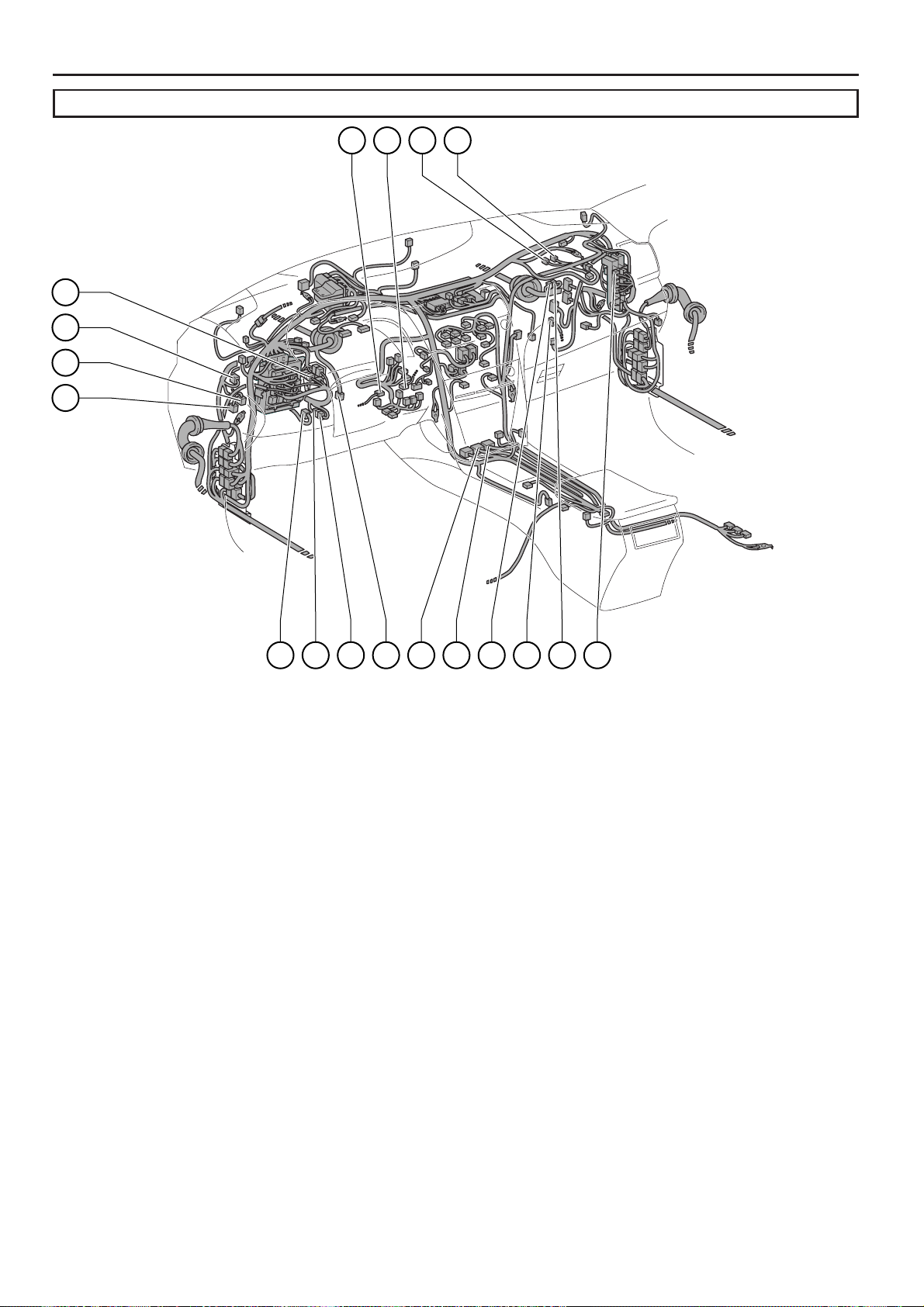
G ELECTRICAL WIRING ROUTING
4
6
(*1)
Position of Parts in Engine Compartment
[2GR–FE]
A35
(*2)
A26
A29
A1
A1
A8
A37
* 1:w/o VSC
* 2:w/ VSC TMC Made
A 1 Fog Lamp (Front LH)
A 2 Ambient Temp. Sensor
A 3 Horn (High)
A 4 Horn (Low)
A 5 Engine Hood Courtesy SW
A 8 Headlamp (LH High)
A13 Airbag Sensor (Front LH)
A14 Speed Sensor (Front LH)
A16 Brake Fluid Level Warning SW
A27A25A28A34
A23
A2A4
A3A5 A13 A1
A23 Security Horn
A25 Skid Control ECU with Actuator
A26 Skid Control ECU with Actuator
A27 A/C Pressure Sensor
A28 Airbag Sensor (Front RH)
A29 Headlamp (RH High)
A34 Fog Lamp (Front RH)
A35 Speed Sensor (Front RH)
A37 Windshield Washer Motor
48
CAMRY (EM0250U)

[2GR–FE]
7
9
6
5
8
3
A55
(*3)
A60
Position of Parts in Engine Compartment
(*5)
(*4)
G
A5
B1
A4
A51
A50
A49
* 3:w/ VSC TMMK Made
* 4:TMC Made
* 5:TMMK Made
A43 Junction Connector
A45 Headlamp (LH Low)
A46 Turn Signal and Parking Lamp (Front LH)
A47 Side Marker Lamp (Front LH)
A48 Wireless Door Lock Buzzer
A49 Headlamp (RH Low)
A50 Turn Signal and Parking Lamp (Front RH)
A51 Side Marker Lamp (Front RH)
A52 Washer Level Warning SW
A53 VSV (Air Intake Control)
A54 Cooling Fan ECU
A55 Engine Control Module
A59 Windshield Wiper Motor
A60 Skid Control ECU with Actuator
A4
A4
A4
A4
A52 A54 A53
B 1 Windshield Wiper Motor
CAMRY (EM0250U)
49

G ELECTRICAL WIRING ROUTING
0
4
Position of Parts in Engine Compartment
[2GR–FE]
C17 C11 C12 C16 C15 C5
C2
C1
C4
C7
C8
C9
C13
C 1 Park/Neutral Position SW
C 2 Mass Air Flow Meter
C 3 Starter
C 4 Engine Coolant Temp. Sensor
C 5 Throttle Body Assembly
C 6 VSV (Purge)
C 7 Fuel Injector (No.1)
C 8 Fuel Injector (No.3)
C 9 Fuel Injector (No.2)
C10 Fuel Injector (No.4)
C11 Ignition Coil (No.1)
C1
C6
C3
C1
C23 C21 C18 C19
C12 Ignition Coil (No.3)
C13 Ignition Coil (No.2)
C14 Ignition Coil (No.4)
C15 Air Fuel Ratio Sensor (Bank 1 Sensor 1)
C16 Noise Filter (Ignition RH)
C17 Power Steering Oil Pressure SW
C18 Generator
C19 Generator
C21 A/C Compressor
C23 Engine Oil Pressure SW
50
CAMRY (EM0250U)

[2GR–FE]
5
9
7
9
6
G
Position of Parts in Engine Compartment
C42
C43
C41
C48
C47
C46
C45
C55 C40
C36
C38 C57
V2
V1
C3
C4
C3
C3
C5
C34 VSV (ACM)
C35 Air Fuel Ratio Sensor (Bank 2 Sensor 1)
C36 Fuel Injector (No.5)
C37 Fuel Injector (No.6)
C38 Ignition Coil (No.5)
C39 Ignition Coil (No.6)
C40 VVT Sensor (Bank 1 Exhaust Side)
C41 VVT Sensor (Bank 1 Intake Side)
C42 Camshaft Timing Oil Control Valve (RH Exhaust Side)
C43 Camshaft Timing Oil Control Valve (RH Intake Side)
C44 VVT Sensor (Bank 2 Exhaust Side)
C45 VVT Sensor (Bank 2 Intake Side)
C46 Camshaft Timing Oil Control Valve (LH Exhaust Side)
C47 Camshaft Timing Oil Control Valve (LH Intake Side)
C48 VSV (ACIS)
C49 Noise Filter (Ignition LH)
C50 Crankshaft Position Sensor
C51 Heated Oxygen Sensor (Bank 2 Sensor 2)
C52 Heated Oxygen Sensor (Bank 1 Sensor 2)
C53 A/C Compressor
C55 Engine Control Module
C56 Transmission Control ECU
C57 Junction Connector
C52 C51C50C53 C44 C34 D1
D 1 Starter
V 1 Knock Control Sensor (Bank 2)
V 2 Knock Control Sensor (Bank 1)
CAMRY (EM0250U)
51

G ELECTRICAL WIRING ROUTING
4
4
6
(*1)
Position of Parts in Engine Compartment
[2AZ–FE]
A35
(*2)
A26
A29
A1
A2
A1
A8
A37
* 1:w/o VSC
* 2:w/ VSC TMC Made
A 1 Fog Lamp (Front LH)
A 2 Ambient Temp. Sensor
A 3 Horn (High)
A 4 Horn (Low)
A 5 Engine Hood Courtesy SW
A 6 A/C Condenser Fan Motor
A 7 Radiator Fan Motor
A 8 Headlamp (LH High)
A13 Airbag Sensor (Front LH)
A14 Speed Sensor (Front LH)
A16 Brake Fluid Level Warning SW
A27A25A28A34
A4A23
A6
A2
A23 Security Horn
A24 Engine Control Module
A25 Skid Control ECU with Actuator
A26 Skid Control ECU with Actuator
A27 A/C Pressure Sensor
A28 Airbag Sensor (Front RH)
A29 Headlamp (RH High)
A34 Fog Lamp (Front RH)
A35 Speed Sensor (Front RH)
A37 Windshield Washer Motor
A3A5 A13A7A1
52
CAMRY (EM0250U)

[2AZ–FE]
7
9
6
5
8
G
Position of Parts in Engine Compartment
(*4)
B1
(*3)
A60
A51
A50
A49
A52
* 3:w/ VSC TMMK Made
* 4:TMC Made
* 5:TMMK Made
A45 Headlamp (LH Low)
A46 Turn Signal and Parking Lamp (Front LH)
A47 Side Marker Lamp (Front LH)
A48 Wireless Door Lock Buzzer
A49 Headlamp (RH Low)
A50 Turn Signal and Parking Lamp (Front RH)
A51 Side Marker Lamp (Front RH)
A52 Washer Level Warning SW
A59 Windshield Wiper Motor
A60 Skid Control ECU with Actuator
B 1 Windshield Wiper Motor
(*5)
A5
A4
A4
A4
A4
CAMRY (EM0250U)
53

G ELECTRICAL WIRING ROUTING
6
5
Position of Parts in Engine Compartment
[2AZ–FE]
C7
C11
C17
C19
C18
C9 C13 C8
C12 C10 C14
C5
C6 C2
C1
C1
C4
C3
C1
C 1 Park/Neutral Position SW
C 2 Mass Air Flow Meter
C 3 Starter
C 4 Engine Coolant Temp. Sensor
C 5 Throttle Body Assembly
C 6 VSV (Purge)
C 7 Fuel Injector (No.1)
C 8 Fuel Injector (No.3)
C 9 Fuel Injector (No.2)
C10 Fuel Injector (No.4)
C11 Ignition Coil (No.1)
C12 Ignition Coil (No.3)
C13 Ignition Coil (No.2)
C14 Ignition Coil (No.4)
C15 Air Fuel Ratio Sensor (Bank 1 Sensor 1)
C16 Noise Filter (Ignition RH)
C17 Power Steering Oil Pressure SW
C18 Generator
C19 Generator
54
CAMRY (EM0250U)

[2AZ–FE]
6
5
7
9
8
4
G
Position of Parts in Engine Compartment
C32C20 C21 C22 C33
C23 D1C31C30
C2
C2
C2
C2
C2
C2
C20 Crankshaft Position Sensor
C21 A/C Compressor
C22 Heated Oxygen Sensor (Bank 1 Sensor 2)
C23 Engine Oil Pressure SW
C24 Engine Control Module
C25 Electronically Controlled Transmission Solenoid
C26 Transmission Revolution Sensor (Turbine)
C27 Transmission Revolution Sensor (Counter Gear)
C28 Back–Up Lamp SW
C29 Starter
C30 Knock Control Sensor (Bank 1)
C31 Camshaft Position Sensor
C32 Camshaft Timing Oil Control Valve
C33 Intake Air Control Valve
D 1 Starter
CAMRY (EM0250U)
55

G ELECTRICAL WIRING ROUTING
(*1)
(*1)
Position of Parts in Instrument Panel
E5
E8
E9
E13
E3
E1E6E7 E15
E12E14 E11 E24 E23 E25 E10
E27
E 1 Diode (Door Courtesy Rear LH)
E 2 Diode (Door Courtesy Rear RH)
E 3 Outer Mirror SW
E 5 Diode (Door Courtesy Front LH)
E 6 Main Body ECU
E 7 Main Body ECU
E 8 Main Body ECU
E 9 Main Body ECU
E10 Data Link Connector 3
E11 Automatic Light Control Sensor
E12 Ion Generator
E13 VSC Warning Buzzer
E14 Turn Signal Flasher
E15 Transponder Key ECU
E16 Airbag Squib (Steering Wheel Pad)
E20E18E16E17E21E2 E22E19
* 1:w/o Smart Key System
E30 E32E29 E33 E31
E17 Steering Sensor
E18 Spiral Cable
E19 Windshield Wiper SW Assembly
E20 Windshield Wiper SW Assembly
E21 Headlamp Dimmer SW Assembly
E22 Unlock Warning SW
E23 Ignition SW
E24 Key Interlock Solenoid
E25 Transponder Key Amplifier
E27 A/C Room Temp. Sensor
E29 Power Outlet Socket (Front)
E30 Airbag Sensor Assembly Center
E31 Transmission Control SW
E32 Shift Lock Control ECU
E33 Parking Brake SW
56
CAMRY (EM0250U)

Position of Parts in Instrument Panel
(*2)
1
9
9
0
(*3)(*4)(*2)
G
E40 E50
* 2:w/ Smart Key System
* 3:TMC Made
* 4:TMMK Made
E43
E62E46 E63 E58
E44 E45 E38 E37 E41
E6
E5
E6
E3
E42
E52
E34 Yaw Rate Sensor
E35 Power Outlet Socket (Rear)
E37 Diode (Door Courtesy Front RH)
E38 A/C Amplifier
E39 Blower Motor
E40 Junction Connector
E41 Junction Connector
E42 Junction Connector
E43 Junction Connector
E44 Junction Connector
E45 Junction Connector
E46 Junction Connector
E48 Junction Connector
E49 Junction Connector
E50 ID Code Box
E49E48
E55
E56
E54E51
E57
E35E53
E65 E34
E51 Steering Lock ECU
E52 Power SW
E53 Tire Pressure Warning SW (Reset)
E54 Airbag Squib (Knee Airbag)
E55 Seat Heater SW
E56 Electrical Key Oscillator (Console)
E57 Shift Lock Control ECU
E58 Certification ECU
E59 Certification ECU
E60 Tire Pressure Warning ECU
E61 Option Connector (Bus Buffer)
E62 Junction Connector
E63 Junction Connector
E65 Yaw Rate Sensor
CAMRY (EM0250U)
57

G ELECTRICAL WIRING ROUTING
5
6
2
Position of Parts in Instrument Panel
(*5) (*6) (*5) (*6)
F21 F22
* 5:8 Speaker
* 6:6 Speaker
* 7:8 Speaker w/ Navigation System
* 8:8 Speaker w/o Navigation System
F2
F1
(*7)
(*8)
F6 F9
F8 F4F3 F11
F26
F14 F13 F5
F24
F23
F25
F1
F1
F1
F 1 Combination Meter
F 2 Combination Meter
F 3 Clock
F 4 Hazard Warning Signal SW
F 5 Glove Box Lamp
F 6 Radio Receiver Assembly
F 7 Radio Receiver Assembly
F 8 Radio Receiver Assembly
F 9 Navigation Receiver Assembly
F10 Navigation Receiver Assembly
F 11 Radio Receiver Assembly
F12 Navigation Receiver Assembly
F13 Navigation Receiver Assembly
F7 F17F10
F20 F18 F19
F14 Navigation Receiver Assembly
F15 Antenna Amplifier
F16 A/C Control Assembly
F17 Stereo Jack Adapter
F18 Stereo Component Amplifier
F19 Stereo Component Amplifier
F20 Stereo Component Amplifier
F21 Tweeter (Front LH)
F22 Tweeter (Front LH)
F23 Tweeter (Front RH)
F24 Tweeter (Front RH)
F25 Junction Connector
F26 Radio Receiver Assembly
58
CAMRY (EM0250U)
A58
A22
A21
A18
G
Position of Parts in Instrument Panel
c2c1b1a1
A17 Accelerator Position Sensor
A18 Parking Brake SW
A19 Stop Lamp SW
A21 Cruise Control Clutch SW
A22 Clutch Start SW
A40 Junction Connector
A41 Junction Connector
A42 Junction Connector
A56 Short Connector
A57 Short Connector
A58 Junction Connector
N 1 Airbag Sensor Assembly Center
N1A17A42A41A19 A56A57O1 e1 A40
O 1 Airbag Sensor Assembly Center
a 1 Spiral Cable
Steering Pad SW
b 1 Cruise Control SW
Spiral Cable
c 1 Airbag Squib (Front Passenger’s Airbag Assembly)
c 2 Airbag Squib (Front Passenger’s Airbag Assembly)
e 1 A/C Amplifier
A/C Blower Assembly
CAMRY (EM0250U)
59
G ELECTRICAL WIRING ROUTING
2
7
8
1
0
9
3
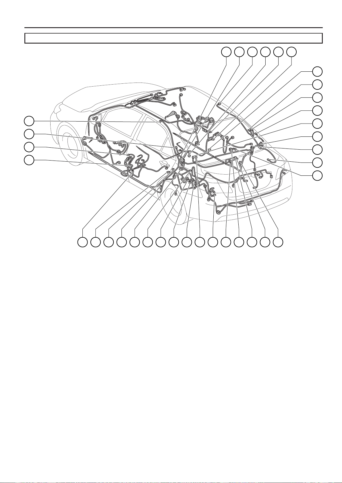
Position of Parts in Body
N18 N29 O16 N19 O6 O7
O8
O1
O1
P1
N21
N34
N6
N7
N 6 Door Courtesy SW (Driver’s Side)
N 7 Side Airbag Sensor (Front LH)
N 8 Pretensioner (LH)
N10 Fuel Suction Pump and Gage Assembly
N11 Electrical Key Oscillator (Rear Seat)
N12 Side Airbag Sensor (Rear LH)
N13 Door Courtesy SW (Rear LH)
N15 Noise Filter (Dome and Stop)
N16 Center Stop Lamp
N17 Canister Pump Module
N18 Noise Filter (Rear Window Defogger)
N19 Rear Window Defogger
N21 Curtain Shield Airbag Squib (LH)
N23 Diode (Luggage Compartment Lamp)
N24 Luggage Compartment Lamp
N25 Electrical Key Oscillator (Inside Luggage Room)
N26 Luggage Compartment Lamp
N28 Junction Connector
N29 Junction Connector
N34 Tire Pressure Warning Antenna and Receiver
N10N11N16N12N15N13N8 N23N28 O14 N17 N25 O15 N26 N24 O9
O 6 Door Courtesy SW (Front Passenger’s Side)
O 7 Side Airbag Sensor (Front RH)
O 8 Pretensioner (RH)
O 9 Side Airbag Sensor (Rear RH)
O10 Door Courtesy SW (Rear RH)
O12 Speaker (Rear LH)
O13 Speaker (Rear RH)
O14 Speaker (Rear LH)
O15 Speaker (Rear RH)
O16 Curtain Shield Airbag Squib (RH)
O17 Door Control Receiver
O18 Door Control Receiver
O19 Electrical Key Antenna
O21 Junction Connector
P 1 Rear Window Defogger
O1
O2
O1
O1
O1
60
CAMRY (EM0250U)

1
0
3
2
Q1
H1
W2
I3
I1
I5
I4
M1
X1
X2
Position of Parts in Body
(*2) (*1)
Q3Q13Q6Q7 Q9 H2Q12 Q5 Q8 Q2
G
H6H5H4 Q11 Q10 W1 H8 H7 J1
J3
J5
S1
S1
S9
g1
S4
S1
S1
S2
S1
* 1:TMC Made
* 2:TMMK Made
* 3:w/ Smart Key System
* 4:w/o Smart Key System
H 1 Speaker (Front Door RH)
H 2 Outer Rear View Mirror (RH)
H 4 Power Window Regulator Motor
(Front Passenger’s Side)
H 5 Door Lock Control SW
H 6 Power Window SW (Front Passenger’s Side)
H 7 Courtesy Lamp (Front Door RH)
H 8 Door Lock Assembly (Front Passenger’s Side)
I 1 Speaker (Front Door LH)
I 3 Outer Rear View Mirror (LH)
I 4 Power Window Regulator Motor (Front LH)
I 5 Power Window Regulator Motor (Front LH)
I 6 Courtesy Lamp (Front Door LH)
I 7 Door Lock Assembly (Driver’s Side)
J 1 Power Window SW (Rear RH)
J 3 Power Window Regulator Motor (Rear RH)
J 5 Door Lock Assembly (Rear RH)
K 1 Power Window SW (Rear LH)
K 3 Power Window Regulator Motor (Rear LH)
K 5 Door Lock Assembly (Rear LH)
M 1 Power Window Master SW
Q 1 Vanity Lamp SW (LH)
Q 2 Vanity Lamp SW (RH)
Q 3 Inner Rear View Mirror
Q 5 Microphone (Navigation)
Q 6 Overhead J/B
Q 7 Vanity Lamp (LH)
I7I6 K3K1 K5 f1
Q 8 Vanity Lamp (RH)
Q 9 Room Lamp (Center)
Q10 Map Lamp (RH)
Q11 Map Lamp (LH)
Q12 Microphone (Navigation)
Q13 Sliding Roof Control ECU and Motor
S 1 License Plate Lamp (RH)
S 2 Rear Combination Lamp (RH)
S 3 Rear Combination Lamp (LH)
S 4 License Plate Lamp (LH)
S 5 Door Lock Assembly (Luggage)
S 6 Luggage Compartment Door Lock Cylinder
S 8 Luggage Compartment Door Lock Cylinder
S 9 Luggage Electrical Key SW
S10 Turn Signal Lamp (Rear LH)
S11 Rear Combination Lamp (LH)
S12 Rear Combination Lamp (RH)
S13 Turn Signal Lamp (Rear RH)
S14 Electrical Key Oscillator (Outside Luggage Room)
S15 Junction Connector
S16 Junction Connector
W 1 Door Outside Handle (Front RH)
W 2 Electrical Key Oscillator (Front Door RH)
X 1 Door Outside Handle (Front LH)
X 2 Electrical Key Oscillator (Front Door LH)
f 1 Speed Sensor (Rear LH)
g 1 Speed Sensor (Rear RH)
S5S14S3 S8S6S16S15
(*4) (*3)
CAMRY (EM0250U)
61

G ELECTRICAL WIRING ROUTING
Position of Parts in Seat
[w/ Power Seat]
U1
U2
Z1
U7
U8
T7 T1 T11 T6 T8
T18U3N27U11 U6 U5U4
O20N3
Y1
N 3 Front Seat Inner Belt (Driver’s Side)
N27 Junction Connector
O20 Junction Connector
T 1 Power Seat Motor
(Front Passenger’s Seat Slide Control)
T 3 Power Seat Motor
(Front Passenger’s Seat Reclining Control)
T 6 Seat Heater (RH)
T 7 Front Seat Inner Belt (Front Passenger’s Side)
T 8 Power Seat SW (Front Passenger’s Seat)
T10 Occupant Classification ECU
T 11 Occupant Classification ECU
T14 Occupant Classification Sensor (Front LH)
T15 Occupant Classification Sensor (Rear LH)
T16 Occupant Classification Sensor (Front RH)
T17 Occupant Classification Sensor (Rear RH)
T18 Junction Connector
T15T14 T10 T16 T17 T3
U 1 Power Seat Motor (Driver’s Seat Slide Control)
U 2 Power Seat Motor (Driver’s Seat Front Vertical Control)
U 3 Power Seat Motor (Driver’s Seat Reclining Control)
U 4 Power Seat Motor (Driver’s Seat Lifter Control)
U 5 Power Seat Motor
(Driver’s Seat Lumbar Support Control)
U 6 Seat Heater (LH)
U 7 Power Seat SW (Driver’s Seat)
U 8 Power Seat SW (Driver’s Seat Lumbar Support Control)
U11 Junction Connector
Y 1 Side Airbag Squib (RH)
Z 1 Side Airbag Squib (LH)
62
CAMRY (EM0250U)

[w/o Power Seat]
G
Position of Parts in Seat
Z1
d2 d3 O3 O4 d5d4N3
d1 Y1
N 3 Front Seat Inner Belt (Driver’s Side)
O 3 Front Seat Inner Belt (Front Passenger’s Side)
O 4 Occupant Classification ECU
Y 1 Side Airbag Squib (RH)
Z 1 Side Airbag Squib (LH)
d 1 Occupant Classification ECU
d 2 Occupant Classification Sensor (Front LH)
d 3 Occupant Classification Sensor (Rear LH)
d 4 Occupant Classification Sensor (Front RH)
d 5 Occupant Classification Sensor (Rear RH)
CAMRY (EM0250U)
63

e
G ELECTRICAL WIRING ROUTING
: Location of Connector Joining Wire Harness and Wire Harness
: Location of Ground Points
[2GR–FE]
Engine Wire
A4
A5
Engine Room Main
Wire
Sensor
Wire
CV1 AB1
Engine Room
No.2 Wire
C5C4 C7
CA3
CA1
CA2
Engine No.2 Wir
A1
A2
64
CAMRY (EM0250U)

: Location of Connector Joining Wire Harness and Wire Harness
: Location of Ground Points
[2AZ–FE]
G
A4
A5
Engine Room Main
Wire
Engine Wire Engine Room
No.2 Wire
C4C6
AB1
CA3
CA1
CA2
Engine No.2 Wire
A1
A2
CAMRY (EM0250U)
65

G ELECTRICAL WIRING ROUTING
Wire
Wire Assembly
No.2 Wire
: Location of Connector Joining Wire Harness and Wire Harness
EQ1
Engine Room
Main Wire
Front Door
LH Wire
IE2
IE1
EN1
EN2
Floor Wire
Roof Wire
EA1NA1
AE7 AE2
Instrument Panel
FE3 FE2
Instrument Panel
AE4AE3
Instrument Panel
AE5
AE6
OF1
Front Door
RH Wire
HE2
HE1
EO1
EO2
Floor
No.2 Wire
OA1Ec1
: Location of Ground Points
E1 E3F1
66
CAMRY (EM0250U)
F2E2A3 F3A6

: Location of Connector Joining Wire Harness and Wire Harness
: Location of Ground Points
G
(*1)
IM1
(*2)
IM2
Electrical Key
Wire Harness LH
IX1
KN1
* 1:w/ Jam Protection
* 2:w/o Jam Protection
Front Door
LH Wire
Rear Door
No.2 Wire
Roof Wire
Floor Wire
Front Door
RH Wire
Skid Control
fO1
Sensor Wire
Electrical Key
Wire Harness RH
N1 S1
HW1 JO1
Luggage
Room Wire
Rear Door
No.1 Wire
Floor
No.3 Wire
P1
O1
gN1
Skid Control
Sensor Wire
Floor
No.2 Wire
SN1
CAMRY (EM0250U)
67

G ELECTRICAL WIRING ROUTING
: Location of Connector Joining Wire Harness and Wire Harness
[w/ Power Seat]
Front Seat
Airbag Assembly LH
Floor No.2 WireFloor Wire Front Seat
OY2 OT1NZ2
Airbag Assembly RH
68
Front Seat RH WireFront Seat LH Wire
CAMRY (EM0250U)

: Location of Connector Joining Wire Harness and Wire Harness
[w/o Power Seat]
G
Front Seat
Airbag Assembly LH
Floor No.2 WireFloor Wire Front Seat
OY2NZ2
Airbag Assembly RH
Front Seat RH Wire
CAMRY (EM0250U)
69

H SYSTEM CIRCUITS
2007 CAMRY
ELECTRICAL WIRING DIAGRAM
SYSTEM CIRCUITS
ABS (w/ VSC TMC Made) . . . . . . . . . . . . . . . . . . . . . . . . . . . . . . . . . . . . . . . . . . . .
ABS (w/ VSC TMMK Made) . . . . . . . . . . . . . . . . . . . . . . . . . . . . . . . . . . . . . . . . . . . 252
ABS (w/o VSC) . . . . . . . . . . . . . . . . . . . . . . . . . . . . . . . . . . . . . . . . . . . . . . . . . . . . . 262
Air Conditioning . . . . . . . . . . . . . . . . . . . . . . . . . . . . . . . . . . . . . . . . . . . . . . . . . . . . 386
Audio System (6 Speaker) . . . . . . . . . . . . . . . . . . . . . . . . . . . . . . . . . . . . . . . . . . . 360
Audio System (8 Speaker w/ Navigation System) . . . . . . . . . . . . . . . . . . . . . . 346
Audio System (8 Speaker w/o Navigation System) . . . . . . . . . . . . . . . . . . . . . 354
Automatic Glare–Resistant EC Mirror . . . . . . . . . . . . . . . . . . . . . . . . . . . . . . . . . 338
Automatic Light Control . . . . . . . . . . . . . . . . . . . . . . . . . . . . . . . . . . . . . . . . . . . . . 160
Back–Up Light . . . . . . . . . . . . . . . . . . . . . . . . . . . . . . . . . . . . . . . . . . . . . . . . . . . . . . 188
Charging . . . . . . . . . . . . . . . . . . . . . . . . . . . . . . . . . . . . . . . . . . . . . . . . . . . . . . . . . . . 100
Clock . . . . . . . . . . . . . . . . . . . . . . . . . . . . . . . . . . . . . . . . . . . . . . . . . . . . . . . . . . . . . . 202
Combination Meter . . . . . . . . . . . . . . . . . . . . . . . . . . . . . . . . . . . . . . . . . . . . . . . . . . 364
Cooling Fan (2GR–FE) . . . . . . . . . . . . . . . . . . . . . . . . . . . . . . . . . . . . . . . . . . . . . . 374
Cruise Control (2AZ–FE) . . . . . . . . . . . . . . . . . . . . . . . . . . . . . . . . . . . . . . . . . . . . 292
Cruise Control (2GR–FE) . . . . . . . . . . . . . . . . . . . . . . . . . . . . . . . . . . . . . . . . . . . . 282
Data Link Connector 3 . . . . . . . . . . . . . . . . . . . . . . . . . . . . . . . . . . . . . . . . . . . . . . 140
Door Lock Control . . . . . . . . . . . . . . . . . . . . . . . . . . . . . . . . . . . . . . . . . . . . . . . . . . 214
Electronically Controlled Transmission and A/T Indicator (2AZ–FE) . . . . . 312
Electronically Controlled Transmission and A/T Indicator (2GR–FE) . . . . 300
Engine Control (2AZ–FE) . . . . . . . . . . . . . . . . . . . . . . . . . . . . . . . . . . . . . . . . . . . . 126
Engine Control (2GR–FE) . . . . . . . . . . . . . . . . . . . . . . . . . . . . . . . . . . . . . . . . . . . . 108
Engine Immobiliser System (w/o Smart Key System) . . . . . . . . . . . . . . . . . . 138
Fog Light . . . . . . . . . . . . . . . . . . . . . . . . . . . . . . . . . . . . . . . . . . . . . . . . . . . . . . . . . . 150
Garage Door Opener . . . . . . . . . . . . . . . . . . . . . . . . . . . . . . . . . . . . . . . . . . . . . . . . 336
Headlight . . . . . . . . . . . . . . . . . . . . . . . . . . . . . . . . . . . . . . . . . . . . . . . . . . . . . . . . . . 144
Horn . . . . . . . . . . . . . . . . . . . . . . . . . . . . . . . . . . . . . . . . . . . . . . . . . . . . . . . . . . . . . . . 204
Ignition (2AZ–FE) . . . . . . . . . . . . . . . . . . . . . . . . . . . . . . . . . . . . . . . . . . . . . . . . . . . 106
Ignition (2GR–FE) . . . . . . . . . . . . . . . . . . . . . . . . . . . . . . . . . . . . . . . . . . . . . . . . . . . 102
Illumination . . . . . . . . . . . . . . . . . . . . . . . . . . . . . . . . . . . . . . . . . . . . . . . . . . . . . . . . 172
Interior Light . . . . . . . . . . . . . . . . . . . . . . . . . . . . . . . . . . . . . . . . . . . . . . . . . . . . . . . 164
Key Reminder (w/o Smart Key System) . . . . . . . . . . . . . . . . . . . . . . . . . . . . . . . 190
Light Auto Turn Off System . . . . . . . . . . . . . . . . . . . . . . . . . . . . . . . . . . . . . . . . . . 160
Luggage Compartment Door Opener . . . . . . . . . . . . . . . . . . . . . . . . . . . . . . . . . 214
Mirror Heater . . . . . . . . . . . . . . . . . . . . . . . . . . . . . . . . . . . . . . . . . . . . . . . . . . . . . . . 342
Multiplex Communication System (CAN) . . . . . . . . . . . . . . . . . . . . . . . . . . . . . . 156
Navigation System . . . . . . . . . . . . . . . . . . . . . . . . . . . . . . . . . . . . . . . . . . . . . . . . . . 346
Power Outlet . . . . . . . . . . . . . . . . . . . . . . . . . . . . . . . . . . . . . . . . . . . . . . . . . . . . . . . 200
Power Seat (Driver’s Seat) . . . . . . . . . . . . . . . . . . . . . . . . . . . . . . . . . . . . . . . . . . . 322
Power Seat (Front Passenger’s Seat) . . . . . . . . . . . . . . . . . . . . . . . . . . . . . . . . . 326
Power Source . . . . . . . . . . . . . . . . . . . . . . . . . . . . . . . . . . . . . . . . . . . . . . . . . . . . . . 72
Power Window . . . . . . . . . . . . . . . . . . . . . . . . . . . . . . . . . . . . . . . . . . . . . . . . . . . . . 206
Radiator Fan and Condenser Fan (2AZ–FE) . . . . . . . . . . . . . . . . . . . . . . . . . . . 380
Rear Window Defogger . . . . . . . . . . . . . . . . . . . . . . . . . . . . . . . . . . . . . . . . . . . . . . 342
Remote Control Mirror . . . . . . . . . . . . . . . . . . . . . . . . . . . . . . . . . . . . . . . . . . . . . . 340
Seat Belt Warning . . . . . . . . . . . . . . . . . . . . . . . . . . . . . . . . . . . . . . . . . . . . . . . . . . . 190
Seat Heater . . . . . . . . . . . . . . . . . . . . . . . . . . . . . . . . . . . . . . . . . . . . . . . . . . . . . . . . . 328
Page
242
70
CAMRY (EM0250U)

H
Page
Shift Lock . . . . . . . . . . . . . . . . . . . . . . . . . . . . . . . . . . . . . . . . . . . . . . . . . . . . . . . . . .
Sliding Roof . . . . . . . . . . . . . . . . . . . . . . . . . . . . . . . . . . . . . . . . . . . . . . . . . . . . . . . . 330
Smart Key System . . . . . . . . . . . . . . . . . . . . . . . . . . . . . . . . . . . . . . . . . . . . . . . . . . 78
∗ Engine Immobiliser
∗ Push Button Start System
∗ Steering Lock
∗ Wireless Door Lock Control
SRS . . . . . . . . . . . . . . . . . . . . . . . . . . . . . . . . . . . . . . . . . . . . . . . . . . . . . . . . . . . . . . . 273
Starting (w/o Smart Key System) . . . . . . . . . . . . . . . . . . . . . . . . . . . . . . . . . . . . . 96
Stop Light . . . . . . . . . . . . . . . . . . . . . . . . . . . . . . . . . . . . . . . . . . . . . . . . . . . . . . . . . . 186
T aillight . . . . . . . . . . . . . . . . . . . . . . . . . . . . . . . . . . . . . . . . . . . . . . . . . . . . . . . . . . . . 172
Theft Deterrent . . . . . . . . . . . . . . . . . . . . . . . . . . . . . . . . . . . . . . . . . . . . . . . . . . . . . 230
Tire Pressure Warning System . . . . . . . . . . . . . . . . . . . . . . . . . . . . . . . . . . . . . . . 270
TRAC (TMC Made) . . . . . . . . . . . . . . . . . . . . . . . . . . . . . . . . . . . . . . . . . . . . . . . . . . 242
TRAC (TMMK Made) . . . . . . . . . . . . . . . . . . . . . . . . . . . . . . . . . . . . . . . . . . . . . . . . . 252
T urn Signal and Hazard Warning Light . . . . . . . . . . . . . . . . . . . . . . . . . . . . . . . . 182
VSC (TMC Made) . . . . . . . . . . . . . . . . . . . . . . . . . . . . . . . . . . . . . . . . . . . . . . . . . . . . 242
VSC (TMMK Made) . . . . . . . . . . . . . . . . . . . . . . . . . . . . . . . . . . . . . . . . . . . . . . . . . . 252
Wiper and Washer . . . . . . . . . . . . . . . . . . . . . . . . . . . . . . . . . . . . . . . . . . . . . . . . . . 196
Wireless Door Lock Control (w/o Smart Key System) . . . . . . . . . . . . . . . . . . 224
320
CAMRY (EM0250U)
71

Power Source
A1
C1
B
C19(A), (C
Generator
(∗1)
(∗2)
)
(∗1)
50A ABS No. 1
B
1
30A ABS No. 2
L
1
50A FAN MAIN
W
1
1
B
1C
120A ALT
SHORT
12
50A RR DEF
50A HTR
40A RDI FAN
40A CDS FAN
10A DOME
21
10A ECU–B NO. 1
21
1
B
1F
Y
1
G
1
W
1
(∗2)
20A STR LOCK
12
25A AMP
G
1
(∗2)
15A HAZ
LG
1
O
1
12
10A ETCS
21
21
1
1
1
1
B
Y
B
BR
R
LG
W
FL MAIN
3. 0W
Battery
1G
15A RADIO NO. 1
21
1
30A EFI MAIN
21
15A H–LP (LH
DRL Relay
15A H–LP (RH
10A MPX–B
10A EFI NO. 1
)
)
L
1
Y
1
7. 5A ALT–S
21
W
1
Y
72
CAMRY (EM0250U)

B
W–B
1
Y
11
4
5
3
W
2
IB
10A MIR HTR
B
VG
1
RR DEF Relay
2
11
∗ 1 : 2GR–FE
∗ 2 : 2AZ–FE
∗ 3 : w/ Smart Key System
∗ 4 : w/o Smart Key System
30A ST/AM2
1
25A DOOR NO. 1
12
7. 5A AM2
12
20A IG2
12
1
1
1
G
(∗3)
B
(∗4)
W
Y
(∗3)
Y
(∗1)
Y
20A A/F
7. 5A S–HORN
1E
15A EFI NO. 2
12
EFI Relay
A/F Relay
S–HORN Relay
6
1E
B
HORN Relay
H–LP (LL) Relay
H–LP (RL) Relay
1
12
10A EFI NO. 3
21
10A HORN
15A H–LP (LL
15A H–LP (RL
)
)
1
1
R
GR
CAMRY (EM0250U)
73

Power Source
(∗4)
O
(∗4)
W(∗4
P(∗4
Y
(∗2)
W
(∗3)
P
(∗3)
B
)
)
B
)
W
(∗3)
(∗3)
W(∗4
P(∗4
P
(∗2)
)
Y
)
Y
∗1 ∗4
(
2
ACC
O
4
AM1
(∗4)
BB
(∗4)(
B
1
AE7
5
)
∗4
E23
Ignition SW
12
4G
(∗3)
6
L
AM1
B
IG1
ST1
IG2
ST2
ACCD
IG1D
1
6AM2
22
B
3
B
(∗3)
(∗1)
Y
Y
(
∗1 ∗3
O
)
712
EA1
16
12
L
4E
(∗3)
10
LG LG
4EEA1
(
)
∗1 ∗3
4M
10
4M
(
∗1 ∗3
O
)
Y
(∗1)
6
4G
7
4G
)
SSW1
SSW2
10
EA1
17
16
B
B
2
3
(
∗1 ∗4
L
(∗3)
V
)
∗3
Y
)
BR
1
(∗1)
BR
1
(∗1)
1
L
AM2
A
(∗3)
11
IG2D
A
(
)(
∗1 ∗3
E6(A), E7(B
Main Body ECU
B
(
)
∗1 ∗4
1
1
5
1
IG2 Relay
6
4E
7
4E
18
EA1
L
(∗3)
V
(∗3)
BR
(∗1)
74
CAMRY (EM0250U)

B
B
1
IA
25A DOOR NO. 2
15A FR FOG
7. 5A RADIO NO. 2
O
(∗4)
W(∗4
P(∗4
Y
(∗2)
W
(∗3)
P
(∗3)
(∗3)
7. 5A OBD
ACC Relay
5
)
)
L
W
(∗4)
O
(∗4)
)
W
∗3
(
P
(∗4)
P
3
II
4
II
9
II
)
∗3
(
2
7. 5A AM1
IG1 Relay
5
2
30A P/SEAT
1
5
1
3
1
3
1
2
4
3
2
7. 5A ECU–ACC
20A PWR OUTLET
10A GAUGE NO. 1
10A ECU IG NO. 1
25A WIP
10A WASH
10A A/C NO. 2
20A S–HTR
7. 5A ECU IG NO. 2
15A TAIL
7. 5A PANEL
V
(∗3)
BR
(∗1)
27
SS2 SS1
SS2 GND SS1
Free
Full
Traveling
GND COM
54
)(
∗3
(
44E
54H
)
∗3
W–B W–B
IG10
W–B
4E5
IM3
TAIL Relay
E49
Junction
Connector
2
W–BW–B
Power SW
E52
)
∗3
(
)
∗3
(
W–B
W–B
10
Y
(∗2)
BR
(∗1)
10
IF
7
II
∗ 1 : 2GR–FE
∗ 2 : 2AZ–FE
∗ 3 : w/ Smart Key System
∗ 4 : w/o Smart Key System
5
2
PWR Relay
7. 5A GAUGE NO. 2
10A IGN
15A INJ
3
1
30A POWER
1
25A RR DOOR LH
25A RR DOOR RH
25A PWR
30A S/ROOF
7. 5A A/C
10A STOP
2
E1
E2
75
CAMRY (EM0250U)
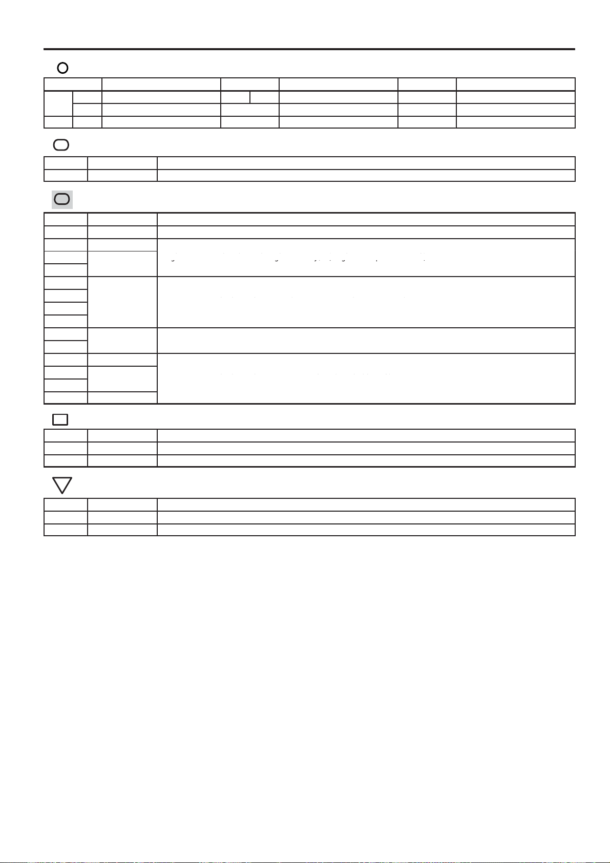
Power Source
C19
:
:
Engine Room Main Wire and Engine Room J/B (Engine Compartment Left)
22
Engine Room Main Wire and Engine Room J/B (Engine Compartment Left)
42
Instrument Panel Wire and J/B No.4 (Instrument Panel Brace Center)
30
Engine Room Main Wire and Instrument Panel J/B (Cowl Side Left)
31
Instrument Panel Wire and Instrument Panel J/B (Cowl Side Left)
:
:
: Parts Location
Code See Page Code See Page Code See Page
A 50 (2GR–FE) E7 B 56 E52 57
C 54 (2AZ–FE) E23 56
E6 A 56 E49 57
Relay Blocks
Code See Page Relay Blocks (Relay Block Location)
1 22 Engine Room R/B (Engine Compartment Left)
Junction Block and Wire Harness Connector
Code See Page Junction Block and Wire Harness (Connector Location)
1C 22 Engine Wire and Engine Room J/B (Engine Compartment Left)
1E 25
1F
1G
4E
4G
4H
4M
IA
IB
IF 30
IG
II
IM 30
Connector Joining Wire Harness and Wire Harness
Code See Page Joining Wire Harness and Wire Harness (Connector Location)
AE7 66 Engine Room Main Wire and Instrument Panel Wire (Right Side of the Instrument Panel J/B)
EA1 66 Instrument Panel Wire and Engine Room Main Wire (Left Kick Panel)
Ground Points
Code See Page Ground Points Location
E1 66 Instrument Panel Left
E2 66 Instrument Panel Brace LH
76
CAMRY (EM0250U)

Memo
CAMRY (EM0250U)
77

Smart Key System
(
)
BAT
(
BAT
W
)
(
BAT
)
(
BAT
)
AM1
L
12 4E
L
)
AM2
A6
1
B
L
12 4M12 4G
G
L–B
30A
ST/AM2
1
G
7. 5A
AM2
2
1
Y
EA17
L
25A
DOOR
NO. 1
2
1
W
G
G
1
1
51
ST Relay
32
25A
DOOR
NO. 2
G
4CA2
W
BATB
2
ALTB
E6(A), E7(B), E8(C), E9(D
Main Body ECU
6
ID16
W
8CA2
Y
Y
W
FL MAIN
3. 0W
Battery
1
1
)
A
GRB
CA11
1
B
C
A1
C3(A), D1(C
Starter
M
W–B
CA27
)
W–B
W–B
VLG
(
C1
W
A4
LB
P
N
Park/Neutral Position SW
A9
WY
10 11
STA NSW
L
Transmission
Control ECU
C56
V
78
A1
A3
CAMRY (EM0250U)
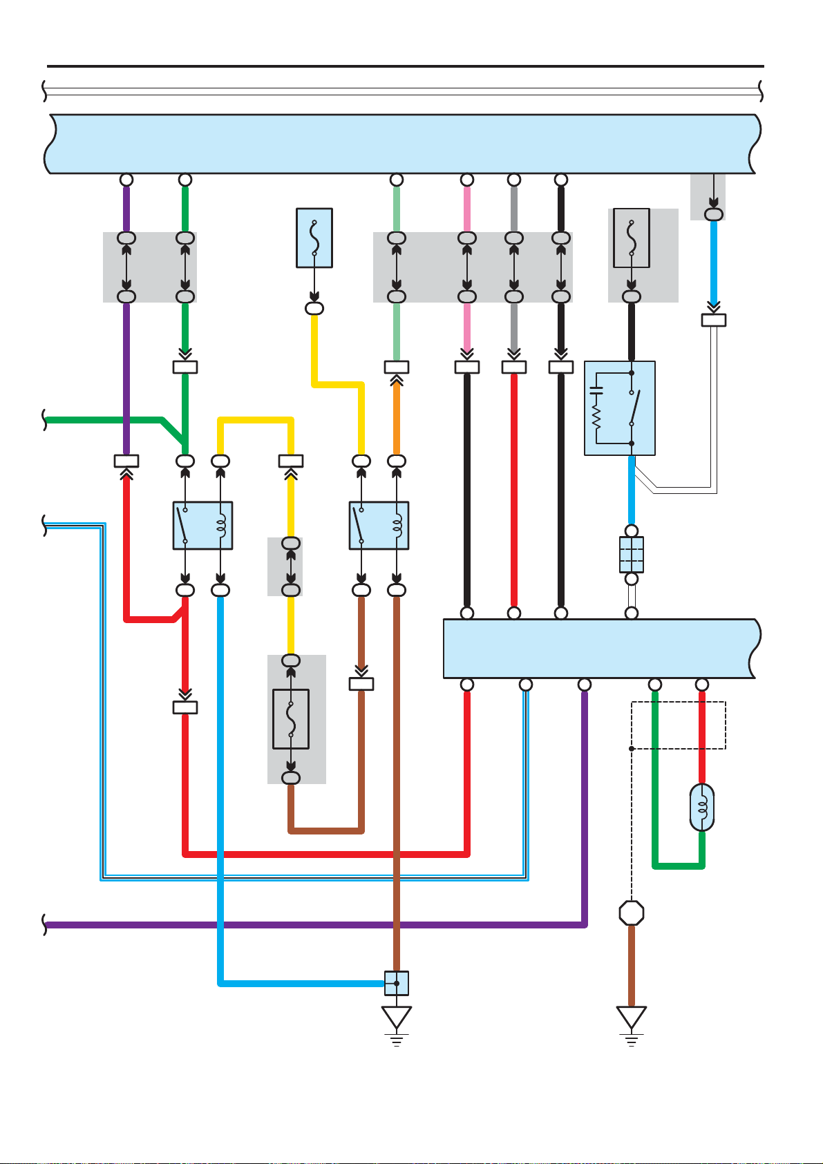
W W
G
L–B
STR2
6D
V
4K8
4E9
V
EA113
R
STR
8B
G
4G9
4F9
G
AE613
G
11
52
31
11
L
R
CA218
R
Y
ST CUT
E6(A), E7(B), E8(C), E9(D
Main Body ECU
IG2D
A11
(
)
BAT
20A
IG2
2
1
AE54
Y
Relay
12 3J
12 3F
Y
IG9
10A IGN
LG
4M10
4E10
LG
EA116
Y
O
11
51
IG2
Relay
32
11
BR
BR
EA118
BR
)
ACCR
)
ACCR STSW TACH
B
(
, C55
)
A
(
STAR
Engine Control Module
A55
STSW
A3
P
4M4
4C5
P
AE58AE515
B
A13 A14 A15
B63
RB
TACH
8C
D4
GR
4K7
4C9
GR
R
R
B
94L
10 4C
B
6 AE5
B
B
NSW STA
B62 A48
L–B
STP
23
(
)
BAT
10A
STOP
IC8
B
2
L
B8
A3
W
A
)
Shielded
(
110
)
B
(
, A42
)
A
(
A41
NE+
B
G
A19
Junction
1
36
STP
V
Stop Lamp SW
Connector
NE–
111
R
IL7
LW
AE29
B
L–B
V
BR
II7
BR
6
5
A2
A43
Junction Connector
L
BR
C5
2
Crankshaft
Position Sensor
C50
1
79
CAMRY (EM0250U)

Smart Key System
W W
E6(A), E7(B), E8(C), E9(D
Main Body ECU
Speed Sensors
LG
A18
B5
)
B
C5
(
FL+ FL– FR+ FR– RL+ RL– RR+ RR–
, A60
)
A
(
, A26
)
C
(
Skid Control ECU with Actuator
A25
W
B
B
V
A4
B6
C6
W
P
A3
B10
C10
CANH CANL SP1
A11
B35
C26
B
L
A17
B9
C9
A25
B14
C15
W
R
)
CANL
L
A20
B7
C7
A6
B27
C17
B
A5
B29
C19
A12
B33
C23
BRW
AE66
(∗1)
(∗2)
(∗3)
W
(∗1)
A19
(∗2)
B8
(∗3)
C8
CANH
C6
W
W
C5
B
)
B
C
(
, E44
)
B
(
C1C2
, E43
)
A
(
Junction Connector
E42
B1B2A1A2
A49 A41
CANL CANH
IMO IMI
A10 A11
G
Y
)
B
(
, C55
)
A
(
A55
A1A7
Engine Control Module
∗ 1 : w/ VSC TMC Made
∗ 2 : w/ VSC TMMK Made
∗ 3 : w/o VSC
A2A8
B4B10
B
)
B
(
, E41
)
A
(
Junction Connector
A40
W
W
B
W
FE314 FE313
W
B
B
B
W
W
Y
G
80
CAMRY (EM0250U)

W W
SPD
12 B
V
EA1
)
(
(
BAT
1A
3
SB
Buzzer
)
10A
MPX–B
R
3L12
3Q1
R
B2IG+ B
R
IF7
ID13
+B(DOME
Master
Warning
)
BAT
2
1
LG
)
10A
DOME
E6(A), E7(B), E8(C), E9(D
Main Body ECU
C9
(IG)
7. 5A
GAUGE
IG12
GR
NO. 2
GR
3G2
3Q9
GR
A13 A1A2
V
3D1
2
3Q12
V
Power Supply Circuit
MULTI LCD
V
3M10
3P3
V
+S
IG2
DRIVE ICMICRO COMPUTER
)
B
(
, F2
)
A
(
F1
Combination Meter
CANH CANL
B
W
W
Y
G
CAN
I/F
B
W
IG2
14 B
SI
WW
3P11
3D3
E2
A12A17 A18
W–B
3Q7
3U2
W–B
3R8
W–B
3Q5
BR
3D10
BR
ES
A24
EA115
BR
GR
A17
)
B
(
, A42
)
A
(
B18
A41
Junction
Connector
CA34
W–B GR
W–B
Y
G
W–B
F1
CAMRY (EM0250U)
3
C7
C57
Junction
Connector
81

Smart Key System
W W
(IG)
14 IM
B
10A
IGN
SLPSLR+
18 B19 B
SLP1IGE
GNDIG2
P
4G5
4A5
P
W–B
E51
Steering
Lock ECU
W–B
BR
4G10
4A10
BR
34
B
E6(A), E7(B), E8(C), E9(D
Main Body ECU
(
BAT
2
M
EA1
11
BLINSGND
5216
O
7
P
)
LIN1
14
)
20A
STR
LOCK
1
B
P
IR9
O
14M
(
BAT
1A2
W
A8
B3
LG
21 AE2
W
)
10A
EFI NO. 1
)
B
(
, A42
)
A
(
Junction Connector
A41
W–B
Y
G
24A
34D
W–B
1
2
Junction Connector
E49
34F
W–B
E50
ID Code Box
815
W–B
10
11 4C
7
Y
6
L
4F
L
AE5
84A 4F784F
O
O
3
LIN1
EFIIEFIOGND +B
G
4F5
4C4
G
AE513
G
W
3J1
O
3C1
W
24D
14F
W
24F
W
W
O
W–B
82
W–B
E1
W–B
E2
CAMRY (EM0250U)

W W
GND3
1C
W–B
Free
Full
Traveling
SSW1
L
4G6
4E6
L
SSW2
16 B17 B
V
4G7
4E7
V
SS1
SS1 SS2
SS2
GND
E6(A), E7(B), E8(C), E9(D
Main Body ECU
SWILINDSINDW
15 B14 B
P
4G4
4E3
P
LG
4G11
4E11
LG
25 B
4G8
11121327
)
O
4E8
O
G
8 9 10 14
SWILINDSINDW
GR
W
R
VC5CODETXCTAGND
G
GR
W
R
W
O
W–B
W–B
COMGND
45
W–B
5
4L
54H
W–B
10 IG
3IM
W–B
4E54E4
E52
Power SW
W
O
W–B
W–B
E1
CAMRY (EM0250U)
83

Smart Key System
W W
G
GR
W
R
E6(A), E7(B), E8(C), E9(D
Main Body ECU
CANN
15 C
W
R
W
GR
G
W
CANP
16 C
L
L
)
E56
Electrical Key Oscillator
(
)
Console
CLGBCLG3
13
R
W
)
B
(
, E59
)
A
(
E58
W
O
W–B
A2728 A
AGNDTXCTCO DE
+B
Certific atio n E CU
W
LIN
O
IND
2AA1
Y
3D5
3R11
Y
8
LP
Security
Indicator
GND1
19
Clock
F3
CANL
HSW
24 B
3E11
3J10
2 AE2
R
2
A5
1
WRR
Engine Hood
CANH
E
17 A10 A
W–B
4F4
4D3
W–BW–B
Courtesy SW
1
Junction Connector
E49
2
BZR
4F11
4K9
O
5
AE2
1
Wireless Door Lock Buzzer
A48
2
BO O
CLG5VC5
ASEL
11
VV
4
ASEL
RC0
A37
GG
EO1EO1
2
+5 DATA
ANT
7
W
1
ANT
12 A11 A30A9A8A40A
CG5B
RDAYRSSI
39 A38 A29 A21 A
R
12 EO113 EO114
Y
3
R
5
RSSI
GND
6
W–B
O18
Door Control
Receiver
84
3
W–B
A3
A2
A43
Junction
Connector
E2
CAMRY (EM0250U)
O19
Electrical
Key Antenna
6
Junction
Connector
O21
O1

W W
N11
Electrical Key Oscillator
(
CLG4 CLGB
Rear Seat
1
Y
EN112
Y
)
3
B
B
E6(A), E7(B), E8(C), E9(D
Main Body ECU
N25
Electrical Key Oscillator
(
Inside Luggage Room
CLG6 CLGB
1
R
R
)
)
3
WW
13 EN114 EN1 15 EN111 EN1
CLG5 CLGB
1
V
12
SN1
V
EN116
V
2
P
13 SN1
P
P
S14
)
Outside Luggage Room
Electrical
Key Oscillator
(
14 A13 A
CG6BCLG6
TSW1
3A
GR
15 IE1
7IX1
B
65 4
3 10
TRG+
2
E58(A), E59(B
Certific atio n E CU
)
R
G
L
W
16 A15 A
CG7BCLG7
SEL1
5
23891
SGTANT1ANT2TRG–TRG–ANT2ANT1SGT
SEL
SEN1
A
14 IE1
IE113
BB
OV V
V
6
SENS
32 A31 A
CG8BCLG8
CLG1
17GRIE1
IX14IX16IX1
CLG
CG1B
34 A33 A22 A
16 IE1
LGRLG
LL
2IX13
P
5
CLGB
12 IE1
RR
IX11IX18
Y
1
+B
GND
R
W–B
W–B
BR
7
X1
Door Outside Handle
(
)
Front LH
X2
Electrical Key Oscillator
(
Front Door LH
)
CAMRY (EM0250U)
85

Smart Key System
W W
ACC
22
2IF
)
(
ACC
)
7. 5A
ECU–ACC
(IG)
13 IM
LG
4A12
LG
10A
IGN
20 B
SH–
P
G
P
G
7A19 A 18 A
TSW5
E6(A), E7(B), E8(C), E9(D
Main Body ECU
IG
15
(IG)
10A
ECU IG
NO. 1
E58(A), E59(B
Certific atio n E CU
12 3C
)
11 3L
L
L
4D5
4F6124F
L
ACC IG
TSW2
R
W–B
15 HE1
R
G
L
BLL
3
61
TRG+ SENS
W1
Door Outside Handle
(
)
Front RH
W
W2
Electrical Key Oscillator
(
Front Door RH
2389
SGTANT1ANT2TRG–TRG–ANT2ANT1SGT
)
SEL2
HE113
6HW17HW1
OPP
410625
SEL
SEN2
14BRHE1 12
4HW1
CLG2
O
HE117
OV
HW13
CG2B
36 A35 A23 A6A4A
16 HE1
GRRGR
BRP
HW12
HE1
W–B
8HW11HW1
YRR
175
+BCLGBCLG
BR
GND
R
R
W–B
W–B
86
CAMRY (EM0250U)

W W
E6(A), E7(B), E8(C), E9(D
Main Body ECU
(
)
BAT
10A
DOME
2
1
P
G
LG
13
ID
IF7
)
G
17 EN1
G
TKUL
2C
OO
19 EN2
O
5SN1SN114
TSW
A2
RR
3F2
3N3
R
EN28
R
SN14
P
12 AE6
Y
R
R
W–B
W–B
17 HE2
W–BW–B
W–B
5
17 IE2
13
W–B
W–B
R
12 3L
12 3H
R
14A
24E14E
R
R
GW–B
1
S9
Luggage Electrical Key SW
2
W–B
1
S15
Junction Connector
9
2
3
W–B
1
Y
Luggage Compartment Door
Lock Cylinder
S8
E49
2
Junction
Connector
E2 S1
CAMRY (EM0250U)
W–B
87

Smart Key System
W W
S–HORN Relay
7. 5A S–HORN
10A HORN
E6(A), E7(B), E8(C), E9(D
Main Body ECU
HORN
25
HORN Relay
)
ACTD
B
5B9
ID11
B
GR
LSWD
L LW–B
LSWP
27 A
LG
ACT+
1
IK2
LG
WW
1A11 1D
5
L
Y
Y
1
A23
Security
Horn
1G1
W
10 1D1B6
B
B
GR
A4
Horn
(
Low
)
11
A3
Horn
(
)
High
IE224 IE29
L
8
I7
7
Door Lock Assembly
IE217
W–B
(
Driver' s Side
)
R
4
M
1
IE2
25
GR
W–B
W
88
CAMRY (EM0250U)

W W
LG
53O
53I
LG
LSWL
20
IP5
GR
GR
)
LSWR
A5
V
3O
4
L
3D
4
GR
L
GR
IJ2
LG
ACT–
3
IF18 IF5
B
EO18EO14EO116
B
E6(A), E7(B), E8(C), E9(D
Main Body ECU
IJ1
L
IP6IP11
G
G
W
W
W–B
HE1
7
LG
7
8
W–B
HE217
W–B
HE29
L
4
MM M
1
25 HE2
H8
LG
LG L
KN110
B
)
Front Passenger' s Side
Door Lock Assembly
(
L
4
1
KN13KN11
GR
6
)
Rear LH
K5
Door Lock Assembly
N29
Junction
Connector
(
9
W–B
KN14JO14
W–B
2
N1
JO110
B
L
4
1
JO13JO11
GR
6
9
W–B
W–B
8
O1
J5
Door Lock Assembly
O21
Junction
Connector
)
Rear RH
(
W–B
W–B
WW
CAMRY (EM0250U)
89

Smart Key System
W W
LCTY
17
LG
)
GND2
4
IO7
IM9
W–B
E6(A), E7(B), E8(C), E9(D
Main Body ECU
HAZ
C
4
93M
93E
WW
8
HAZ
E14
Turn Signal
Flasher
21
PCTY
A
Y
3N5
3C6
Y
EO25
6
RCTY
7
GR
3N6
3C7
GR
EO2
A
DCTY
24
B
L
3F10
3O12
L
13
EN2
GND1
5
IF10
W–B
1IR
W–B
)
∗6
(
W–B
W–B
O6
Y
)
1
Front Passenger' s Side
Door Courtesy SW
(
O10
GR
1
)
Rear RH
Door Courtesy SW
(
L
(∗4)
A1
(∗5)
B1
)
)
B
(
,
)
A
(
Driver' s Side
N6
Door Courtesy SW
(
)
B
(
,
)
A
(
N13
(∗4)
A1
(∗5)
B1
)
Rear LH
Door Courtesy SW
(
2
W–B
10
11
W–B
)
∗7
(
E49
Junction Connector
W–B
(∗6)
W–B
(∗7)
WW
6
513
W–B
W–B
90
E2
CAMRY (EM0250U)

W
(
)
BAT
E6(A), E7(B), E8(C), E9(D
Main Body ECU
N28S15
5EN1
Junction
Connector
TR+
SN116
LGCY
25 1
A
EN217
W
13
14
WW
3SN1
W
)
ILE
B
B
B
B
21
IR5
BRV
)
R
∗6
7
B
Map Lamp
CTY
Overhead J/B
6
(
E
8
EQ116
)
)
W
∗6
∗7
(
(
Q6
)
W
∗7
(
1
)
Center
(
OFFONDOOR
Room Lamp
2
Q9
3
10A
DOME
2
1
LG
)(
∗7
(
)(
RR
∗6
(
S5
W–B
(∗6)
W–B
(∗7)
W
)
Luggage
Door Lock Assembly
(
3
2
W–B
1
9
W–B
Junction
Connector
)
V
1
M
)
∗6
∗6
(
(
W–B
)
∗6
(
W–B
)
)
W
W
W–B
15 EQ1
∗7
(
WW
6IR
)
∗7
(
)
∗7
(
∗ 4 : TMC M ade
∗ 5 : TMMK Made
∗ 6 : w/ Sliding Roof
∗ 7 : w/o Sliding Roof
∗7
(
W
EQ118EQ111
EQ17
)
∗7
IL10
ID13
LG
)
∗6
S1
91
CAMRY (EM0250U)

Smart Key System
N13
N6
:
System Outline
∗ Steering lock
Receiving signals from the power SW and the key, the certification ECU sends instruction for locking and unlocking the
steering lock to the steering lock ECU (Built in the steering lock) in order to activate the motor. The steering lock ECU detects
position of the lock bar and stops the motor at the specified position.
: Parts Location
Code See Page Code See Page Code See Page
A3 48 (2GR–FE) E8 C 56 N11 60
A4 48 (2GR–FE) E9 D 56
A5 48 (2GR–FE) E14 56
A19 59 E41 B 57 N25 60
A23 48 (2GR–FE) E42 A 57 N28 60
A25 C 48 (2GR–FE) E43 B 57 N29 60
A26 A 48 (2GR–FE) E44 C 57 O6 60
A40 A 59 E49 57 O10 60
A41 A 59 E50 57 O18 60
A42 B 59 E51 57 O19 60
A43 49 (2GR–FE) E52 57 O21 60
A48 49 (2GR–FE) E56 57 Q6 61
A55 A 49 (2GR–FE) E58 A 57 Q9 61
A60 B 49 (2GR–FE) E59 B 57 S5 61
C1 A 50 (2GR–FE) F1 A 58 S8 61
C3 A 50 (2GR–FE) F2 B 58 S9 61
C50 51 (2GR–FE) F3 58 S14 61
C55 B 51 (2GR–FE) H8 61 S15 61
C56 51 (2GR–FE) I7 61 W1 61
C57 51 (2GR–FE) J5 61 W2 61
D1 C 51 (2GR–FE) K5 61 X1 61
E6 A 56
E7 B 56
A 60 X2 61
B 60
A 60
B 60
Relay Blocks
Code See Page Relay Blocks (Relay Block Location)
1 22 Engine Room R/B (Engine Compartment Left)
92
CAMRY (EM0250U)

:
Junction Block and Wire Harness Connector
25
25
Engine Room Main Wire and Engine Room J/B (Engine Compartment Left)
36
Instrument Panel Wire and J/B No.3 (Behind the Combination Meter)
36
Instrument Panel No.2 Wire and J/B No.3 (Behind the Combination Meter)
42
Instrument Panel Wire and J/B No.4 (Instrument Panel Brace Center)
30
Engine Room Main Wire and Instrument Panel J/B (Cowl Side Left)
31
Instrument Panel Wire and Instrument Panel J/B (Cowl Side Left)
Instrument Panel Wire and Instrument Panel J/B (Cowl Side Left)
30
30
Floor Wire and Instrument Panel J/B (Cowl Side Left)
Code See Page Junction Block and Wire Harness (Connector Location)
1A
1B
1D
1G 22
3C
3D
3E
3F
3G
3H
3I
3J
3L
3M
3N
3O
3P
3Q
3R
3U
4A
4C
4D
4E
4F
4G
4H
4K
4L
4M
IC
ID
IF 30
IG
II
IJ
IK
IL
IM
IO
IP
IR 30 Instrument Panel Wire and Instrument Panel J/B (Cowl Side Left)
CAMRY (EM0250U)
93

Smart Key System
:
66
Engine Room Main Wire and Instrument Panel Wire (Instrument Panel Right)
64 (2GR–FE)
Engine Wire and Engine Room Main Wire (Inside of the Engine Room R/B and Engine Room J/B)
64 (2GR–FE)
Engine Wire and Engine Room Main Wire (Inside of the Engine Room R/B and Engine Room J/B)
66
Instrument Panel Wire and Floor Wire (Left Kick Panel)
66
Instrument Panel Wire and Floor No.2 Wire (Right Kick Panel)
66
Front Door RH Wire and Instrument Panel Wire (Right Kick Panel)
66
Front Door LH Wire and Instrument Panel Wire (Left Kick Panel)
:
64 (2GR–FE)
Front Left Fender
Connector Joining Wire Harness and Wire Harness
Code See Page Joining Wire Harness and Wire Harness (Connector Location)
AE2 66 Engine Room Main Wire and Instrument Panel Wire (Right Side of the Instrument Panel J/B)
AE5
AE6
CA1
CA2
CA3
EA1 66 Instrument Panel Wire and Engine Room Main Wire (Left Kick Panel)
EN1
EN2
EO1
EO2
EQ1 66 Instrument Panel Wire and Roof Wire (Lower Part of Front Pillar LH)
FE3 66 Instrument Panel No.2 Wire and Instrument Panel Wire (Instrument Panel Center)
HE1
HE2
HW1 67 Front Door RH Wire and Electrical Key Wire Harness RH (Inside of the Front Door RH)
IE1
IE2
IX1 67 Front Door LH Wire and Electrical Key Wire Harness LH (Inside of the Front Door LH)
JO1 67 Rear Door No.1 Wire and Floor No.2 Wire (Right Center Pillar)
KN1 67 Rear Door No.2 Wire and Floor Wire (Left Center Pillar)
SN1 67 Luggage Room Wire and Floor Wire (Luggage Room Left)
Ground Points
Code See Page Ground Points Location
A1
A2
A3 66 Left Cowl Side Panel
C5 64 (2GR–FE) Right Side of the Cylinder Block
C7 64 (2GR–FE) Left Side of the Cylinder Block
E1 66 Instrument Panel Left
E2 66 Instrument Panel Brace LH
F1 66 Instrument Panel Left
N1 67 Left Rear Quarter Panel
O1 67 Right Rear Quarter Panel
S1 67 Lower Back Panel Center
94
CAMRY (EM0250U)

Memo
CAMRY (EM0250U)
95

Starting without Smart Key System
ACC
AM1
4
O
AM2
II4
5
IG1
ST1
IG2
ST2
3
7
GR
7. 5A AM1
IA1
B
1
1F
120A ALT
1G1
W
E23
B
Ignition SW
AE71
B
1
30A ST/AM2
L
AE72
L
G
11
51
ST Relay
32
11
GR
W–B
CA11
4CA2
)
A/T
(
W
)
M/T
(
R
96
FL MAIN
3. 0W
Battery
B
(
A/T)A1
(
)
1
B
B
1
C
M/T
M
)
C
(
, D1
)
B
(
, C29
)
A
(
Starter
C3
W–B
A1
W–B
A3
R(M/T
W(A/T
)
)
CAMRY (EM0250U)

GR
5
3F
3E
5
GR
EA16
∗ 1 : 2AZ–FE A/T
)
R
M/T
(
1
2
)
G
M/T
(
CA39
)
R
M/T
(
A22
Clutch Start SW
A41(A), A42(B
Junction Connector
B11
AA
12
)
R
∗1
18 CA2 CA2
)(
∗1
SB
(
(
2GR–FE
B62
(
2AZ–FE
D52
)
B
(
, C55
)
D
(
C24
Engine Control Module
NSW
STA
A48
C48
VLG
CA27
(
2GR–FE
(
2AZ–FE
,
)
A
(
, A55
)
C
(
A24
)
L–B
(
2GR–FE
)
)
)
B
(
,
)
A
(
C1
)
)
Park/Neutral
)
P
N
Position SW
)
2AZ–FE
(
10
B
)(
PB
∗1
(
8
)
Y
A/T
)
Y
A/T
(
4A(2GR–FE
4B(2AZ–FE
BL
9A(2GR–FE
5B(2AZ–FE
W
)
)
)
A/T
(
L
(
2GR–FE
)
)
)
P
2GR–FE
(
)
11
NSW
10
STA
Y
)
2GR–FE
(
Transmission
Control ECU
C56
R(M/T
W(A/T
)
R(M/T
)
)
R(M/T
W(A/T
)
)
W(A/T
Y(2GR–FE
)
)
97
CAMRY (EM0250U)

Starting without Smart Key System
C3
A
D1
C
:
:
22
Engine Room Main Wire and Engine Room J/B (Engine Compartment Left)
36
Instrument Panel Wire and J/B No.3 (Behind the Combination Meter)
:
CA1
Engine Wire and Engine Room Main Wire (Inside of the Engine Room R/B and Engine Room J/B)
CA2
Engine Wire and Engine Room Main Wire (Inside of the Engine Room R/B and Engine Room J/B)
:
A1
Front Left Fender
: Parts Location
Code See Page Code See Page Code See Page
A22 59 C1 B 54 (2AZ–FE) C56 51 (2GR–FE)
A24 C 52 (2AZ–FE)
A41 A 59
A42 B 59 C24 D 55 (2AZ–FE) E23 56
A55 A 49 (2GR–FE) C29 B 55 (2AZ–FE)
C1 A 50 (2GR–FE) C55 B 51 (2GR–FE)
Relay Blocks
Code See Page Relay Blocks (Relay Block Location)
1 22 Engine Room R/B (Engine Compartment Left)
Junction Block and Wire Harness Connector
Code See Page Junction Block and Wire Harness (Connector Location)
1F
1G
3E
3F
IA 30 Engine Room Main Wire and Instrument Panel J/B (Cowl Side Left)
II 31 Instrument Panel Wire and Instrument Panel J/B (Cowl Side Left)
50 (2GR–FE)
54 (2AZ–FE)
51 (2GR–FE)
55 (2AZ–FE)
Connector Joining Wire Harness and Wire Harness
Code See Page Joining Wire Harness and Wire Harness (Connector Location)
AE7 66 Engine Room Main Wire and Instrument Panel Wire (Right Side of the Instrument Panel J/B)
64 (2GR–FE)
65 (2AZ–FE)
64 (2GR–FE)
65 (2AZ–FE)
CA3 65 (2AZ–FE)
EA1 66 Instrument Panel Wire and Engine Room Main Wire (Left Kick Panel)
Ground Points
Code See Page Ground Points Location
64 (2GR–FE)
65 (2AZ–FE)
A3 66 Left Cowl Side Panel
98
CAMRY (EM0250U)

Memo
CAMRY (EM0250U)
99
 Loading...