


 Loading...
Industrial Inverter
 For 3-phase induction motors
Instruction Manual
TOSVERTTM VF-S11
< Simplified manual >
1-phase 240V class |
0.2 |
2.2kW |
||
3-phase 240V class |
0.4 |
15kW |
||
3-phase 500V class |
0.4 |
15kW |
||
3-phase 600V class |
0.75 |
15kW |
||
|
|
|
|
|
|
|
|
|
|
|
|
|
|
|
NOTICE
1.Make sure that this instruction manual is delivered to the end user of the inverter unit.
2.Read this manual before installing or operating the inverter unit, and store it in a safe place for reference.
E6581160
Safety precautions
Contents
Read first
Connection
Operations
Basic VF-S11 operations
Monitoring the operation status
Measures
to satisfy the standards
Table of parameters and data
Specifications
Before making a service call
Measures
to satisfy the standards
Peripheral devices
Table of parameters and data
Specifications
Before making a service call -Trip information and remedies
Inspection and maintenance
Warranty
Disposal of the inverter
I
1
2
3
4
5
6
7
8
9
9
10
11
12
13
14
15
16
2004 Ver. 108/109
|
E6581160 |
||
|
|
|
|
I. Safety precautions |
|
|
I |
|
|
|
|
|
|
|
|
The items described in these instructions and on the inverter itself are very important so that you can use the inverter safely, prevent injury to yourself and other people around you as well as to prevent damage to property in the area. Thoroughly familiarize yourself with the symbols and indications shown below and then continue to read the manual. Make sure that you observe all warnings given.
Explanation of markings
|
|
Marking |
Meaning of marking |
|
|
Danger |
Indicates that errors in operation may lead to death or serious injury. |
|
|
|
|
|
|
|
|
|
|
Warning |
Indicates that errors in operation may lead to injury (*1) to people or that these errors may |
|
|
cause damage to physical property. (*2) |
|
|
|
|
|
(*1) Such things as injury, burns or shock that will not require hospitalization or long periods of outpatient treatment.
(*2) Physical property damage refers to wide-ranging damage to assets and materials.
Meanings of symbols
Marking |
Meaning of marking |
||
|
|
|
Indicates prohibition (Don't do it). |
|
|
|
What is prohibited will be described in or near the symbol in either text or picture form. |
|
|
|
Indicates something mandatory (must be done). |
|
|
|
What is mandatory will be described in or near the symbol in either text or picture form. |
|
|
|
|
|
|
|
Indicates danger. |
|
|
|
What is dangerous will be described in or near the symbol in either text or picture form. |
|
|
|
|
|
|
|
Indicates warning. |
|
|
|
What the warning should be applied to will be described in or near the symbol in either text or picture form. |
|
|
|
|
Q Limits in purpose
This inverter is used for controlling speeds of three-phase induction motors in general industrial use.
 Safety precautions
The inverter cannot be used in any device that would present danger to the human body or from which malfunction or error in operation would present a direct threat to human life (nuclear power control device, aviation and space flight control device, traffic device, life support or operation system, safety device, etc.). If the inverter is to be used for any special purpose, first get in touch with the supplier.
This product was manufactured under the strictest quality controls but if it is to be used in critical equipment, for example, equipment in which errors in malfunctioning signal output system would cause a major accident, safety devices must be installed on the equipment.
Do not use the inverter for loads other than those of properly applied three-phase induction motors in general industrial use. (Use in other than properly applied three-phase induction motors may cause an accident.)
1

E6581160
I |
Q General Operation |
 Danger
• Never disassemble, modify or repair.
This can result in electric shock, fire and injury. For repairs, call your sales distributor.
Disassembly |
|
|
||
prohibited |
|
|
||
|
|
|
• |
Never remove the front cover when power is on or open door if enclosed in a cabinet. |
|
|
|
• |
The unit contains many high voltage parts and contact with them will result in electric shock. |
|
|
|
Don't stick your fingers into openings such as cable wiring hole and cooling fan covers. |
|
|
|
|
• |
This can result in electric shock or other injury. |
Prohibited |
Don't place or insert any kind of object into the inverter (electrical wire cuttings, rods, wires etc.). |
|||
|
|
|
• |
This can result in electric shock or fire. |
|
|
|
Do not allow water or any other fluid to come in contact with the inverter. |
|
|
|
|
|
This can result in electric shock or fire. |
|
|
|
• |
Turn power on only after attaching the front cover or closing door if enclosed in a cabinet. |
|
|
|
|
If power is turned on without the front cover attached or closing door if enclosed in a |
|
|
|
• |
cabinet, this can result in electric shock or other injury. |
|
|
|
||
|
|
|
If the inverter begins to emit smoke or an unusual odor, or unusual sounds, immediately turn power off. |
|
|
|
|
|
If the equipment is continued in operation in such a state, the result may be fire. Call your local sales |
Mandatory |
|
|||
• |
agency for repairs. |
|||
|
|
|
Always turn power off if the inverter is not used for long periods of time since there is a possibility of |
|
|
|
|
|
malfunction caused by leaks, dust and other material. If power is left on with the inverter in that state, it |
|
|
|
|
may result in fire. |
|
|
|
|
|
|
|
Warning |
|
|
||
|
|
|
|
|
|
|
|
|
|||
|
|
|
|
|
|
|
|
|
|
|
|
|
|
|
|
• |
Do not touch heat radiating fins or discharge resistors. |
|
|
||||
|
|
|
|
|
These device are hot, and you'll get burned if you touch them. |
||||||
|
|
|
|
|
|
|
|
|
|
|
|
Prohibited |
|
|
|
|
|
|
|
|
|||
contact |
|
|
|
|
|
|
|
|
|||
|
|
|
|
• |
Avoid operation in any location where there is direct spraying of the following solvents or other |
||||||
|
|
|
|
|
chemicals. |
|
|
|
|
||
|
|
|
|
|
The plastic parts may be damaged to a certain degree depending on their shape, and there is a |
||||||
|
|
|
|
|
|||||||
|
|
|
|
|
possibility of the plastic covers coming off. |
|
|
|
|
||
|
|
|
|
|
If the chemical or solvent is anything other than those shown below, please contact us in advance. |
||||||
Prohibited |
|
||||||||||
|
|
|
|
|
|
|
|
||||
|
|
|
|
(Table 1) Examples of applicable chemicals |
(Table 2) |
Examples of unapplicable |
|||||
|
|
|
|
|
and solvents |
|
|
chemicals and solvents |
|||
|
|
|
|
|
Acetic acid (density of 10% or less) |
|
|
Acetone |
|
||
|
|
|
|
|
Hydrochloric acid (density of 10% or less) |
|
|
Benzene |
|
||
|
|
|
|
|
Sulfuric acid (density of 10% or less) |
|
|
Chloroform |
|
||
|
|
|
|
|
Sodium chloride |
|
|
Ethylene chloride |
|
||
|
|
|
|
|
Hexane |
|
|
Ethyl acetate |
|
||
|
|
|
|
|
Triethylene glycol |
|
|
Glycerin |
|
||
|
|
|
|
|
|
|
|
|
|
Tetrachloroethylene |
|
|
|
|
|
|
|
|
|
|
|
Trichloroethylene |
|
|
|
|
|
|
|
|
|
|
|
Xylene |
|
|
|
|
|
|
|
|
|
|
|
|
|
2

|
E6581160 |
||
|
|
|
|
Q Transportation & installation |
|
|
I |
 Danger
•Do not install or operate the inverter if it is damaged or any component is missing.
This can result in electric shock or fire. Please consult your local sales agency for repairs. Call your local sales agency for repairs.
Prohibited |
• |
Do not place any inflammable objects nearby. |
|||
|
|
|
• |
If a flame is emitted due to malfunction, it may result in a fire. |
|
|
|
|
Do not install in any location where the inverter could come into contact with water or other fluids. |
||
|
|
|
|
This can result in electric shock or fire. |
|
|
|
|
• |
Must be used in the environmental conditions prescribed in the instruction manual. |
|
|
|
|
• |
Use under any other conditions may result in malfunction. |
|
|
|
|
Mount the inverter on a metal plate. |
||
|
|
|
• |
The rear panel gets very hot. Do not install in an inflammable object, this can result in fire. |
|
|
|
|
Do not operate with the front panel cover removed. This can result in electric shock. Failure to do so |
||
Mandatory |
• |
can lead to risk of electric shock and can result in death or serious injury. |
|||
An emergency stop device must be installed that fits with system specifications (e.g. shut off input |
|||||
|
|
|
|||
|
|
|
|
power then engage mechanical brake). Operation cannot be stopped immediately by the inverter |
|
|
|
|
• |
alone, thus risking an accident or injury. |
|
|
|
|
All options used must be those specified by Toshiba. |
||
|
|
|
|
The use of any other option may result in an accident. |
|
|
|
|
|
|
Warning |
|
|
|
|
|
|
|
|
• |
When transporting or carrying, do not hold by the front panel covers. |
||
|
|
||||
|
|
• |
The covers may come off and the unit will drop out resulting in injury. |
||
|
|
Do not install in any area where the unit would be subject to large amounts of vibration. |
|||
|
|
||||
Prohibited |
That could result in the unit falling, resulting in injury. |
||||
•The main unit must be installed on a base that can bear the unit's weight.
If the unit is installed on a base that cannot withstand that weight, the unit may fall resulting in injury.
•If braking is necessary (to hold motor shaft), install a mechanical brake.
Mandatory |
The brake on the inverter will not function as a mechanical hold, and if used for that purpose, injury |
|
may result. |
||
|
Q Wiring
 Danger
•Do not connect input power to the output (motor side) terminals (U/T1,V/T2,W/T3). That will destroy the inverter and may result in fire.
•Do not connect resistors to the DC terminals (across PA-PC or PO-PC). That may cause a fire.
Prohibited • Within ten minutes after turning off input power, do not touch wires of devices (MCCB) connected to the input side of the inverter.
That could result in electric shock.
3

E6581160
I |
|
|
|
|
|
Danger |
•Electrical installation work must be done by a qualified expert.
Connection of input power by someone who does not have that expert knowledge may result in fire or electric shock.
•Connect output terminals (motor side) correctly.
If the phase sequence is incorrect, the motor will operate in reverse and that may result in injury.
•Wiring must be done after installation.
If wiring is done prior to installation that may result in injury or electric shock
•The following steps must be performed before wiring.
(1) Turn off all input power.
Mandatory |
(2) |
Wait at least ten minutes and check to make sure that the charge lamp is no longer lit. |
|
(3) |
Use a tester that can measure DC voltage (800VDC or more), and check to make sure that the |
||
|
|||
|
|
voltage to the DC main circuits (across PA-PC) is 45V or less. |
|
|
If these steps are not properly performed, the wiring will cause electric shock. |
||
•Tighten the screws on the terminal board to specified torque.
If the screws are not tightened to the specified torque, it may lead to fire.
•Check to make sure that the input power voltage is +10%, -15% of the rated power voltage written on the rating label (±10% when the load is 100% in continuous operation).
If the input power voltage is not +10%, -15% of the rated power voltage (±10% when the load is 100% in continuous operation) this may result in fire.
•Ground must be connected securely.
If the ground is not securely connected, it could lead to electric shock or fire when a malfunction or current leak occurs.
Be Grounded
 Warning
•Do not attach equipment (such as noise filters or surge absorbers) that have built-in capacitors to the output (motor side) terminals.
That could result in a fire.
Prohibited
Q Operations
|
|
|
|
|
|
|
Danger |
|
|
|
|
|
|
|
|
|
|
|
|
• |
Do not touch inverter terminals when electrical power is going to the inverter even if the motor is |
||
|
|
|
|
|
stopped. |
||
|
|
|
|
• |
Touching the inverter terminals while power is connected to it may result in electric shock. |
||
|
|
|
|
||||
|
|
|
|
Do not touch switches when the hands are wet and do not try to clean the inverter with a damp cloth. |
|||
|
|
|
|
• |
Such practices may result in electric shock. |
||
|
Prohibited |
||||||
|
Do not go near the motor in alarm-stop status when the retry function is selected. |
||||||
|
|
|
|
|
The motor may suddenly restart and that could result in injury. |
||
|
|
|
|
|
Take measures for safety, e.g. attaching a cover to the motor, against accidents when the motor |
||
|
|
|
|
|
unexpectedly restarts. |
||
|
|
|
|
• |
Turn input power on after attaching the front cover. |
||
|
|
|
|
|
When installed inside a cabinet and using with the front cover removed, always close the cabinet doors |
||
|
|
|
|
|
first and then turn power on. If the power is turned on with the front cover or the cabinet doors open, it |
||
|
|
|
|
• |
may result in electric shock. |
||
|
Mandatory |
||||||
|
Make sure that operation signals are off before resetting the inverter after malfunction. |
||||||
|
|
|
|
|
If the inverter is reset before turning off the operating signal, the motor may restart suddenly causing |
||
|
|
|
|
|
injury. |
||
|
|
|
|
|
|
|
|
|
|
|
|
|
4 |
||

|
|
|
|
E6581160 |
|||
|
|
|
|
|
|
|
|
|
|
|
|
|
|
|
I |
|
|
|
Warning |
|
|
|
|
|
|
|
|
|
|
||
•Observe all permissible operating ranges of motors and mechanical equipment. (Refer to the motor's instruction manual.)
Not observing these ranges may result in injury.
Prohibited
When sequence for restart after a momentary failure is selected (inverter)
|
|
|
|
|
|
Warning |
|
|
|
|
|
|
|
|
|
|
|
|
|
|
|
|
|
• |
Stand clear of motors and mechanical equipment. |
||
|
|
|
|
If the motor stops due to a momentary power failure, the equipment will start suddenly after power |
||
|
|
|
• |
recovers. This could result in unexpected injury. |
||
Mandatory |
Attach warnings about sudden restart after a momentary power failure on inverters, motors and |
|||||
|
|
|
|
equipment for prevention of accidents in advance. |
||
When retry function is selected (inverter)
|
|
|
|
|
|
Warning |
|
|
|
|
|
|
|
|
|
|
|
|
|
|
|
|
|
• |
Stand clear of motors and equipment. |
||
|
|
|
|
If the motor and equipment stop when the alarm is given, selection of the retry function will restart them |
||
|
|
|
• |
suddenly after the specified time has elapsed. This could result in unexpected injury. |
||
Mandatory |
Attach warnings about sudden restart in retry function on inverters, motors and equipment for |
|||||
|
|
|
|
prevention of accidents in advance. |
||
Maintenance and inspection
 Danger
•Do not replace parts.
This could be a cause of electric shock, fire and bodily injury. To replace parts, call the local sales agency.
Prohibited
•The equipment must be inspected every day.
If the equipment is not inspected and maintained, errors and malfunctions may not be discovered and that could result in accidents.
•Before inspection, perform the following steps.
Mandatory |
(1) |
Turn off all input power to the inverter. |
(2) |
Wait at least ten minutes and check to make sure that the charge lamp is no longer lit. |
|
|
(3) |
Use a tester that can measure DC voltages (800VDC or more), and check to make sure that the |
|
|
voltage to the DC main circuits (across PA-PC) is 45V or less. |
|
If inspection is performed without performing these steps first, it could lead to electric shock. |
|
5

|
|
|
|
|
E6581160 |
|
|
|
|
Contents |
|
|
|
I |
Safety precautions |
1 |
|
|
|
||||
|
|
1. |
Read first |
7 |
|
|
|
||||
|
|
|
1.1 |
Check product purchase .................................................................................................................................... |
7 |
|
|
|
1.2 |
Contents of the product...................................................................................................................................... |
9 |
|
|
|
1.3 |
Installation.......................................................................................................................................................... |
9 |
|
|
2. |
Connection..................................................................................................................................................................... |
10 |
|
|
|
|
2.1 |
Standard connections ........................................................................................................................................ |
10 |
|
|
|
2.2 |
Description of terminals...................................................................................................................................... |
12 |
|
|
3. |
Operations ..................................................................................................................................................................... |
19 |
|
|
|
|
3.1 |
Simplified operation of the VF-S11..................................................................................................................... |
19 |
|
|
|
3.2 |
How to operate the VF-S11................................................................................................................................ |
23 |
|
|
4. |
Basic VF-S11 operations................................................................................................................................................ |
27 |
|
|
|
|
4.1 |
Flow of status monitor mode |
28 |
|
|
|
|||
|
|
|
4.2 |
How to set parameters ....................................................................................................................................... |
29 |
|
|
5. |
Monitoring the operation status...................................................................................................................................... |
36 |
|
|
|
|
5.1 |
Status monitor mode .......................................................................................................................................... |
36 |
|
|
|
5.2 |
Display of trip information................................................................................................................................... |
40 |
|
|
6. |
Measures to satisfy the standards |
44 |
|
|
|
||||
|
|
|
6.1 |
How to cope with the CE directive ..................................................................................................................... |
44 |
|
|
|
6.2 |
Compliance with UL Standard and CSA Standard............................................................................................. |
48 |
|
|
7. |
Table of parameters and data ........................................................................................................................................ |
50 |
|
|
|
|
7.1 |
User parameters ................................................................................................................................................ |
50 |
|
|
|
7.2 |
Basic parameters ............................................................................................................................................... |
50 |
|
|
|
7.3 |
Extended parameters......................................................................................................................................... |
53 |
|
|
8. |
Specifications................................................................................................................................................................. |
70 |
|
|
|
|
8.1 |
Models and their standard specifications ........................................................................................................... |
70 |
|
|
|
8.2 |
Outside dimensions and mass ........................................................................................................................... |
73 |
|
|
9. |
Before making a service call - Trip information and remedies........................................................................................ |
76 |
|
|
|
|
9.1 |
Trip causes/warnings and remedies................................................................................................................... |
76 |
6

E6581160
1. Read first 
Thank you for your purchase of the Toshiba “TOSVERT VF-S11” industrial inverter.
This manual is a simplified version.
If you need a detailed explanation, refer to the full version of English manual (E6581158). |
1 |
|
This is the Ver. 108 / Ver. 109 CPU version inverter.
Please be informed that CPU version will be frequently upgraded.
1.1Check product purchase
Before using the product you have purchased, check to make sure that it is exactly what you ordered.
|
Rating label |
|
Inverter main unit |
|
|
|
|
|
|
Series name |
|
|
|
|
Power supply |
VF-S11 |
|
||
|
|
1PH-200/240V-0.75kW/1HP |
||
Motor capacity |
Warning label |
|
Carton box |
|
Name plate |
|
|
|
|
Name plate |
Warning label |
Type indication label |
Inverter Type |
|
Inverter rated output |
|
|
|
capacity |
|
Instruction manual |
Power supply |
|
Related input current |
|
|
|
|
|
This manual |
Related output |
|
current |
|
|
|
EMC plate |
|
7
E6581160
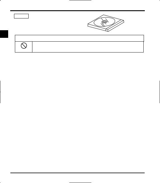
CD-ROM E6581167
Contains the instruction manual in digital form.
Some models do not come with this CD-ROM.
1
Warning
Do not play this CD-ROM on any audio CD player to avoid hearing loss due to very loud noises or damage to the CD player.
Prohibited
[System requirements]
OS: Microsoft Windows 98/NT/2000/XP Browser: Internet Explorer 4.0 or later CPU: Pentium 100MHz or more Memory: 32MB or more
DOS/V-based personal computer
[Starting the browsing program]
When you insert this CD-ROM in the CD-ROM drive, the program “index.htm” in the root directory starts automatically. When you want to close the browsing program or if it does not start automatically, open Windows Explorer and click “\index.htm” under “CD-ROM drive” to display the top window.
[Software needed for browsing] Adobe Acrobat Reader 4.0J or later
[Trade names and trademarks]
Microsoft Windows and Windows logos are trademarks or registered trademarks of Microsoft Corporation in the U.S.A.
Adobe Acrobat is a trademark of Adobe Systems Incorporated.
Other company names and product names referred to in this manual are trade names and registered trademarks, respectively.
[Copyright]
This manual and other documentation included with the inverter are publications of Toshiba Schneider Inverter Corporation, and all rights to these publications, including copyrights, are reserved by the said corporation.
[Duplication]
No part of the contents of the CD-ROM shall be reproduced without written permission from Toshiba Schneider Inverter Corporation.
[Exclusions]
Toshiba Schneider Inverter Corporation shall have no liability for any damage of any kind caused by the use of this CDROM.
8
E6581160
1.2Contents of the product
Explanation of the name plate label. Always shut power off first then check the ratings label of inverter held in a cabinet.
Type |
Form |
1 |
|
 V
V  F
F  S
S  11
11  S
S  -
-  2
2  0
0  0
0  7
7  P
P  L
L  E
E  -
-  W
W  N
N  -
-  A
A  2
2  2
2 
|
|
|
|
|
|
|
|
Model name |
|
Input (AC) voltage |
|
Applicable motor |
|||
|
|
capacity |
|||||
|
|
|
|
|
|||
|
|
|
|
|
|
|
|
TOSVERT |
|
2 : 200V to 240V |
|
002 : |
0.2kW |
||
VF-S11series |
|
4 : 380V to 500V |
|
004 : |
0.4kW |
||
|
|
|
6 : 525V to 600V |
|
005 : 0.55kW |
||
|
|
||||||
|
|
|
|
|
007 |
: 0.75kW |
|
|
|
|
|
|
|||
|
|
|
|
|
015 |
: |
1.5kW |
|
|
|
|
|
|||
|
|
|
|
|
022 |
: |
2.2kW |
Number of |
|
|
|
037 |
: |
3.7kW |
|
|
|
|
055 |
: |
5.5kW |
||
power phases |
|
|
|
||||
|
|
|
075 |
: |
7.5kW |
||
|
|
|
|
|
|||
S: single-phase |
|
|
|
110 : |
11kW |
||
None: |
|
|
|
150 : |
15kW |
||
three-phase |
|
|
|
|
|
|
|
|
|
|
|
|
|
||
|
|
|
|
|
|
|
Additional functions I |
|
Default interface |
||||
|
|
logic* |
||||
|
|
|
|
|
|
|
|
|
|
|
|
|
|
None: No filter inside |
|
WN, AN: Negative |
||||
M: Built-in basic filter |
|
|||||
|
WP |
: Positive |
||||
L: Built-in |
|
|||||
high-attenuation |
|
|
|
|||
|
|
|
||||
EMI filter |
|
|
|
|||
|
|
|
|
|
|
|
Operation panel |
|
|
Additional function II |
|||
|
|
|
|
|
||
P: Provided |
|
|
None: Standard product |
|||
|
E: Enclosed type |
|
||||
|
|
|
|
U: Open type |
|
|
|
|
|
|
R: With a built-in RS-485 |
||
|
|
|
|
circuit board |
|
|
Special specification code
A : is the number
*This code represents the factory default logic setting. You can switch from one input/output logic to the other using slide switch SW1.
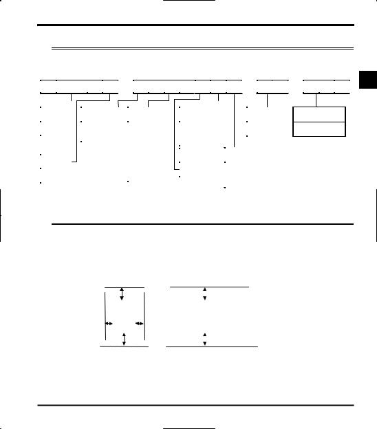
1.3Installation
Install the inverter in a well-ventilated indoor place and mount it on a flat metal plate in portrait orientation.
If you are installing more than one inverter, the separation between inverters should be at least 5 centimeters, and they should be arranged in horizontal rows. If the inverters are horizontally arranged with no space between them (side-by-side installation), peel off the ventilation seals on top of the inverter. It is necessary to decrease the current if the inverter is operated at over 50°C.
•Standard installation |
•Side-by-side installation |
||||||||||||||
|
|
|
|
|
|
|
|
|
|
|
10 cm or more |
||||
|
|
|
|
10 cm or more |
|
|
|
|
|
||||||
|
|
|
|
|
|
|
|
|
|
|
|
|
|
|
Remove seals on top |
|
|
|
|
|
|
|
|
|
|
|
|
|
|
|
|
|
|
|
VFS11 |
|
|
|
|
|
|
VFS11 |
VFS11 |
VFS11 |
|
||
|
5 cm or more |
|
|
|
5 cm or more |
|
|
|
|
||||||
|
|
|
|
|
|
|
|
|
|
|
|
|
|
||
|
|
|
|
|
|
|
|
|
|
|
|
|
|
|
|
|
|
|
|
|
|
|
|
|
|
|
|
|
|
|
|
|
|
|
|
|
|
|
|
|
|
|
|
10 cm or more |
|||
|
|
|
|
|
10 cm or more |
|
|
|
|
|
|||||
|
|
|
|
|
|
|
|
|
|
|
|
|
|
|
|
The space shown in the diagram is the minimum allowable space. Because air cooled equipment has cooling fans built in on the top or bottom surfaces, make the space on top and bottom as large as possible to allow for air passage.
Note: Do not install in any location where there is high humidity or high temperatures and where there are large amounts of dust, metallic fragments and oil mist.
9
E6581160
2.Connection 
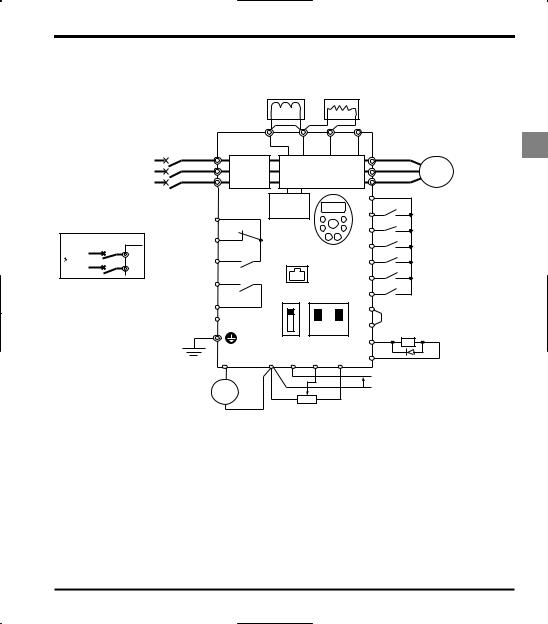
2.1Standard connections
2.1.1 Standard connection diagram 1
2
This diagram shows a standard wiring of the main circuit.
Standard connection diagram - SINK (Negative) (common:CC)
DC reactor (DCL) |
Braking resistor (option) |
|
*2 (option) |
||
|
P0 PA/+ PB PC/-
Main circuit power supply |
|
MCCB |
|
|
|
U/T1 |
Motor |
|
240V class: three-phase 200-240V |
R/L1 |
|
|
|
|
|||
|
-50/60Hz |
|
S/L2 |
Noise |
Power circuit |
|
V/T2 |
I M |
500V class: three-phase 380-500V |
T/L3 |
filter *5 |
|
W/T3 |
||||
|
-50/60Hz |
|
|
|
|
|||
600V class: three-phase 525-600V |
*1 |
|
Control |
F |
|
Forward |
||
|
-50/60Hz |
|
|
|
|
|||
|
|
|
|
FLC |
circuit |
R |
|
Reverse |
|
|
|
|
|
|
|||
|
|
Protective function |
FLB |
VF-S11 |
RES |
|
Reset |
|
|
|
|
|
|
||||
|
MCCB(2P) |
activation output |
|
Operation panel S1 |
|
Preset-speed 1 |
||
Power supply |
R/L1 |
|
FLA |
|
|
|
|
|
1 |
200~240V |
|
|
S2 |
|
Preset-speed 2 |
||
-50/60Hz |
S/L2 |
|
|
Connector for |
|
|||
|
|
|
|
common serial |
|
|
||
|
|
|
|
RY |
|
|
||
|
|
|
|
communicationsS3 |
|
Preset-speed 3 |
||
*1: The T/L3 terminal is not provided for single-phase models.
Use the R/L1 and S/L2 terminal as input terminals.
*2: The inverter is supplied with the PO and the PA/+ terminals shorted by means of a shorting bar.
Before installing the DC reactor (DCL), remove the bar.
*3: When using the OUT output terminal in sink logic mode, short the NO and CC terminals.
*4: If you are using a 600V model, be sure to connect an input reactor (ACL).
*5: 600V models have no noise filter inside.
SW1 |
FM |
VIA |
CC |
Common |
|
SOURCE |
V |
V |
|||
|
|
PLC |
P24 |
|
Speed reach |
OUT |
Ry |
signal output |
|
|
|
Frequency meter (ammeter)
-
7.5V-1mA (or 4-20mA)
SINK |
I |
I NO |
*3 |
|
|
|
|
CC |
|
CC VIA |
VIB |
PP |
|
|
|
|
|||
|
|
|
+ |
Voltage signal: 0-10V |
|
|
|
- |
|
|
|
|
(Current signal: 4-20mA) |
|
|
|
|
|
|
External potentiometer (1~10kΩ)
(or input voltage signal across VIB-CC terminals: 0-10V)
10
E6581160
2.1.2 Standard connection diagram 2
Standard connection diagram - SOURCE (Positive) (common:P24)
DC reactor (DCL) |
Braking resistor (option) |
*2 (option) |
|
|
|
|
|
|
P0 |
|
PA/+ |
PB |
PC/- |
|
|
2 |
||
Main circuit power supply |
|
MCCB |
R/L1 |
|
|
|
|
|
|
|
U/T1 |
Motor |
||
240V class: three-phase 200-240V |
|
S/L2 |
Noise |
|
|
|
|
|
|
V/T2 |
|
|
||
|
-50/60Hz |
|
|
|
|
Power circuit |
|
I M |
|
|||||
|
|
|
|
T/L3 |
filter *5 |
|
|
W/T3 |
|
|||||
500V class: three-phase 380-500V |
|
|
|
|
|
|
|
|
||||||
|
*1 |
|
|
|
|
|
|
|
|
|
|
|||
|
-50/60Hz |
|
|
|
|
Control |
|
|
P24 |
|
|
|
||
600V class: three-phase 525-600V |
|
|
|
|
|
|
|
|
|
|||||
|
-50/60Hz |
|
|
|
FLC |
|
circuit |
|
|
F |
|
Forward |
|
|
|
|
|
|
|
|
|
|
|
|
|
|
|||
|
|
Protective function |
FLB |
|
VF-S11 |
|
R |
|
Reverse |
|
||||
|
|
|
|
|
|
|
|
|||||||
Power supply |
MCCB(2P) |
R/L1 activation output |
FLA |
|
|
Operation panel RES |
|
Reset |
|
|||||
1 200~240V |
|
|
|
|
|
|
|
|
|
S1 |
|
Preset-speed 1 |
|
|
-50/60Hz |
|
S/L2 |
|
|
|
|
|
|
Connector for |
|
|
|||
|
|
|
|
|
|
|
|
|
|
|
||||
|
|
|
|
|
|
|
|
|
|
|
|
|||
|
|
|
|
|
RY |
|
|
|
common serial |
|
Preset-speed 2 |
|
||
|
|
|
|
|
|
|
|
communications S2 |
|
|
||||
*1: The T/L3 terminal is not provided |
Low-speed |
|
|
|
SW1 |
FM |
VIA |
S3 |
|
Preset-speed 3 |
|
|||
for single-phase models. |
signal output |
RC |
|
SOURCE |
V |
V |
|
|
||||||
|
|
|
|
|
||||||||||
Use the R/L1 and S/L2 terminal |
|
|
|
|
|
P24 |
|
|
|
|||||
|
|
|
|
|
|
|
|
*3 |
|
|
||||
as input terminals. |
|
24Vdc input |
PLC |
PLC |
|
|
|
OUT |
|
|
||||
|
|
|
|
|
|
|
|
|
||||||
|
|
|
|
|
|
|
|
|
|
|
|
|
|
|
*2: The inverter in supplied with the PO |
|
|
|
|
SINK |
I |
I |
NO |
|
Ry |
|
|||
and the PA/+ terminals shorted by |
|
|
|
|
|
|
||||||||
means of a shorting bar. |
|
|
|
|
|
|
|
|
|
|
Speed reach signal |
|
||
|
|
FM |
|
CC |
VIA |
VIB |
PP |
CC |
|
output |
|
|||
Before installing the DC reactor (DCL), |
|
|
|
|
||||||||||
|
|
|
|
|
||||||||||
remove the bar. |
|
|
Meter |
+ |
|
|
|
|
|
+ |
|
|
|
|
*3: When using the NO output terminal in |
|
|
|
|
|
Voltage signal: 0-10V |
|
|||||||
source logic mode, short the P24 and |
|
Frequency |
|
|
|
|
|
- |
|
|||||
|
|
|
|
|
|
(Current signal: 4-20mA) |
|
|||||||
OUT terminals. |
|
|
|
meter |
|
|
|
|
|
|
|
|||
|
|
|
(ammeter) |
|
|
|
|
|
|
|
|
|
||
*4: If you are using a 600V model, be sure |
|
- |
|
|
|
|
External potentiometer (1~10kΩ) |
|
||||||
to connect an input reactor (ACL). |
|
7.5V-1mA |
|
|
|
|
|
|||||||
|
|
|
|
|
(or input voltage signal across VIB-CC terminals: 0-10V) |
|
||||||||
*5: 600V models have no noise filter inside. |
|
|
|
|
|
|||||||||
(or 4-20mA) |
|
|
|
|
|
|
|
|
|
|||||
|
|
|
|
|
|
|
|
|
|
|
|
|
||
11

E6581160
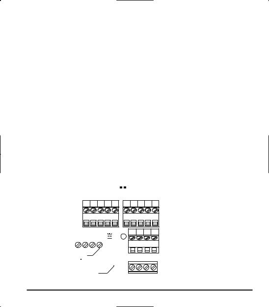
2.2Description of terminals
2.2.1 |
Power circuit terminals |
|
|
||
|
|
In case of the lug connector, cover the lug connector with insulated tube, or use the insulated lug |
|||
|
|
connector. |
|
|
|
|
|
|
|
|
|
2 |
|
Screw size |
tightening torque |
|
|
|
M3.5 screw |
0.9Nm |
7.1lb y in |
|
|
|
|
M4 screw |
1.3Nm |
10.7lb y in |
|
|
|
M5 screw |
2.5Nm |
22.3lb y in |
|
|
|
M6 screw |
4.5Nm |
40.1lb y in |
|
Q Power circuit
|
|
Terminal symbol |
|
|
|
Terminal function |
|
|
|||||
|
|
|
|
|
|
|
Grounding terminal for connecting inverter. There are 3 terminals in total. 2 terminals in |
||||||
|
|
|
|
|
|
|
the terminal board, 1 terminal in the cooling fin. |
|
|
||||
|
|
|
|
|
|
|
240V class: single-phase 200 to 240V-50/60Hz |
|
|
||||
|
|
|
|
|
|
|
|
three-phase 200 to 240V-50/60Hz |
|
|
|||
|
|
R/L1,S/L2,T/L3 |
500V class: three-phase 380 to 500V-50/60Hz |
|
|
||||||||
|
|
|
|
|
|
|
600V class: three-phase 525 to 600V-50/60Hz |
|
|
||||
|
|
|
|
|
|
|
* Single-phase input: R/L1 and S/L2 terminals |
|
|
||||
|
|
U/T1,V/T2,W/T3 |
Connect to a (three-phase induction) motor. |
|
|
||||||||
|
|
|
|
|
|
|
|
|
|||||
|
|
PA/+ PB |
|
Connect to braking resistors. |
|
|
|
|
|||||
|
|
|
Change parameters H, H, H, H if necessary. |
|
|||||||||
|
|
|
|
|
|
|
|
||||||
|
|
PC/- |
|
|
|
|
This is a negative potential terminal in the internal DC main circuit. DC common power |
||||||
|
|
|
|
|
|
can be input across the PA terminals (positive potential). |
|
|
|||||
|
|
|
|
|
|
|
|
|
|||||
|
|
PO PA/+ |
|
Terminals for connecting a DC reactor (DCL: optional external device). Shorted by a |
|||||||||
|
|
|
short bar when shipped from the factory. Before installing DCL, remove the short bar. |
||||||||||
|
|
|
|
|
|
|
|||||||
2.2.2 |
Selection of wiring materials |
|
|
|
|||||||||
|
|
|
|
|
|
|
|
|
|
|
|
|
|
|
|
|
|
|
|
Capacity of |
|
|
|
Wire size (See Note 4) |
|
||
|
Voltage class |
|
applicable |
Inverter model |
Power circuit |
DC reactor |
Braking resistor/ |
Earth cable |
|||||
|
|
(mm2) (Note 1.) |
(optional) (mm2) |
Braking unit |
(mm2) |
||||||||
|
|
|
|
|
|
motor (kW) |
|
|
|
|
(optional) (mm2) |
|
|
|
|
|
|
|
|
0.2 |
|
VFS11S-2002PL |
2.0 |
(2.0) |
2.0 |
2.0 |
3.5 |
|
Single-phase |
|
0.4 |
|
VFS11S-2004PL |
2.0 |
(2.0) |
2.0 |
2.0 |
3.5 |
|||
|
|
0.75 |
|
VFS11S-2007PL |
2.0 |
(2.0) |
2.0 |
2.0 |
3.5 |
||||
|
240V class |
|
|
|
|
||||||||
|
|
|
|
1.5 |
|
VFS11S-2015PL |
2.0 |
(2.0) |
2.0 |
2.0 |
3.5 |
||
|
|
|
|
|
|
|
|||||||
|
|
|
|
|
|
2.2 |
|
VFS11S-2022PL |
2.0 |
(2.0) |
3.5 |
2.0 |
3.5 |
|
|
|
|
|
|
0.4 |
|
VFS11-2004PM |
2.0 |
(2.0) |
1.25 |
2.0 |
3.5 |
|
|
|
|
|
|
0.55 |
|
VFS11-2005PM |
2.0 |
(2.0) |
2.0 |
2.0 |
3.5 |
|
|
|
|
|
|
0.75 |
|
VFS11-2007PM |
2.0 |
(2.0) |
2.0 |
2.0 |
3.5 |
|
Three-phase |
|
1.5 |
|
VFS11-2015PM |
2.0 |
(2.0) |
2.0 |
2.0 |
3.5 |
|||
|
|
2.2 |
|
VFS11-2022PM |
2.0 |
(2.0) |
2.0 |
2.0 |
3.5 |
||||
|
240V class |
|
|
|
4.0 |
|
VFS11-2037PM |
2.0 |
(2.0) |
3.5 |
2.0 |
3.5 |
|
|
|
|
|
|
|
5.5 |
|
VFS11-2055PM |
5.5 |
(2.0) |
8.0 |
2.0 |
5.5 |
|
|
|
|
|
|
7.5 |
|
VFS11-2075PM |
8.0 |
(5.5) |
14 |
3.5 |
5.5 |
|
|
|
|
|
|
11 |
|
VFS11-2110PM |
14 (8.0) |
14 |
5.5 |
8.0 |
|
|
|
|
|
|
|
15 |
|
VFS11-2150PM |
22 |
(14) |
22 |
14 |
8.0 |
12
|
|
|
|
|
|
|
E6581160 |
|
|
|
|
|
|
|
|
|
|
|
|
|
|
Capacity of |
|
|
Wire size (See Note 4) |
|
|
|
|
|
Voltage class |
applicable |
Inverter model |
Power circuit |
DC reactor |
Braking resistor/ |
Earth cable |
|
|
|
(mm2) (Note 1.) |
(optional) (mm2) |
Braking unit |
(mm2) |
|
|
|||
|
|
motor (kW) |
|
|
|
(optional) (mm2) |
|
|
|
|
|
0.4 |
VFS11-4004PL |
2.0 (2.0) |
2.0 |
2.0 |
3.5 |
|
|
|
|
0.75 |
VFS11-4007PL |
2.0 (2.0) |
2.0 |
2.0 |
3.5 |
|
|
|
|
1.5 |
VFS11-4015PL |
2.0 (2.0) |
2.0 |
2.0 |
3.5 |
|
|
|
Three-phase |
2.2 |
VFS11-4022PL |
2.0 (2.0) |
2.0 |
2.0 |
3.5 |
|
|
|
4.0 |
VFS11-4037PL |
2.0 (2.0) |
2.0 |
2.0 |
3.5 |
|
|
|
|
500V class |
|
|
||||||
|
5.5 |
VFS11-4055PL |
2.0 (2.0) |
3.5 |
2.0 |
3.5 |
|
|
|
|
|
|
|
||||||
|
|
7.5 |
VFS11-4075PL |
3.5 (2.0) |
5.5 |
2.0 |
3.5 |
|
2 |
|
|
11 |
VFS11-4110PL |
5.5 (2.0) |
8.0 |
2.0 |
5.5 |
|
|
|
|
15 |
VFS11-4150PL |
8.0 (5.5) |
14 |
3.5 |
5.5 |
|
|
|
|
0.75 |
VFS11-6007P |
2.0 |
2.0 |
2.0 |
3.5 |
|
|
|
|
1.5 |
VFS11-6015P |
2.0 |
2.0 |
2.0 |
3.5 |
|
|
|
Three-phase |
2.2 |
VFS11-6022P |
2.0 |
2.0 |
2.0 |
3.5 |
|
|
|
4.0 |
VFS11-6037P |
2.0 |
2.0 |
2.0 |
3.5 |
|
|
|
|
600V class |
5.5 |
VFS11-6055P |
2.0 |
2.0 |
2.0 |
3.5 |
|
|
|
|
7.5 |
VFS11-6075P |
2.0 |
2.0 |
2.0 |
3.5 |
|
|
|
|
11 |
VFS11-6110P |
3.5 |
3.5 |
2.0 |
3.5 |
|
|
|
|
15 |
VFS11-6150P |
5.5 |
5.5 |
2.0 |
5.5 |
|
|
Note 1: Sizes of the wires connected to the input terminals R/L1, S/L2 and T/L3 and the output terminals U/T1, V/T2 and W/T3 when the length of each wire does not exceed 30m.
The numeric values in parentheses refer to the sizes of wires to be used when a DC reactor is connected. Note 2: For the control circuit, use shielded wires 0.75 mm2 or more in diameter.
Note 3: For grounding, use a cable with a size equal to or larger than the above.
Note 4: The wire sizes specified in the above table apply to HIV wires (cupper wires shielded with an insulator with a maximum allowable temperature of 75°C) used at an ambient temperature of 50°C or less.
Note 5: If there is a need to bring the inverter into UL compliance, use wires specified in Chapter 6.
2.2.3 Control circuit terminals
The control circuit terminal |
SW1 |
|
board is common to all |
PLC |
SOURCE |
|
||
equipment. |
|
SINK |
|
||
P24 OUT NO FM CC |
FM VIA
PP |
VIA |
VIB |
CC |
V |
V |
|
I |
I |
|||||
|
|
|
|
|||
|
|
|
|
|||
|
|
|
|
|
|
|
|
|
|
|
|
|
|
|
|
|
|
|
|
FLA FLB FLC |
RY |
RC |
PLC S1 |
S2 |
S3 |
M3 screw |
|
|
|
|
|
|
|
|
F |
R |
RES |
CC |
|
(0.5N m) |
|
|
||||
|
|
|
|
|
|
|
|
|
|
|
|
|
|
Optional connector (RJ45)
Factory default settings of slide switches SW1: SINK (Negative) side (WN, AN type)
SOURCE (Positive) side (WP type) FM: V side
VIA: V side
Wire size
Solid wire: 0.3 1.5 (mm2) Stranded wire: 0.3 1.5 (mm2)
(AWG 22 16) Sheath strip length: 6 (mm)
Screwdriver: Small-sized flat-blade screwdriver (Blade thickness: 0.4 mm or less, blade width: 2.2 mm or less)
13
|
|
|
|
|
|
|
|
|
|
|
|
|
|
|
|
|
|
E6581160 |
|||||||
|
|
|
|
Q Control circuit terminals |
|
|
|
|
|
|
|
|
|
|
|
|
|
|
|
|
|
|
|
||
|
|
|
Terminal |
Input/output |
|
Function |
Electrical |
|
Inverter internal circuits |
||||||||||||||||
|
|
|
symbol |
|
specifications |
|
|||||||||||||||||||
|
|
|
|
|
|
|
|
|
|
|
|
|
|
|
|
|
|
|
|
|
|
|
|
||
|
|
|
|
|
|
Shorting across F-CC causes |
|
|
|
|
|
|
|
|
|
|
|
|
|
|
|
|
|
|
|
|
|
|
F |
Input |
input |
forward rotation; open causes slow- |
|
|
|
|
|
|
|
|
|
|
|
|
|
|
|
|
|
|
|
|
|
|
down and stop. (When ST is always |
|
|
|
|
|
|
|
|
|
|
|
|
|
|
|
|
|
|
|
|||
|
|
|
|
|
|
|
|
|
|
|
|
|
|
|
|
|
|
|
|
|
|
|
|
||
|
|
|
|
|
ON) |
|
|
|
|
|
|
|
|
|
|
|
|
|
|
|
|
|
|
|
|
|
|
|
|
|
contact |
|
|
|
|
|
|
|
|
|
|
|
|
|
|
|
|
|
|
|
|
|
|
|
|
|
Shorting across R-CC causes |
|
|
|
24V |
SW1 |
|||||||||||||||
2 |
|
|
R |
Input |
reverse rotation; open causes slow- |
No voltage |
|
|
|
SINK |
PLC |
||||||||||||||
|
|
|
|
|
|||||||||||||||||||||
|
|
down and stop. (When ST is always |
|
|
|
|
|
|
SOURCE |
||||||||||||||||
|
|
|
|
programmable |
contact input |
|
|
|
|
|
|
|
|
|
|
|
|
|
|
|
|
|
|
||
|
|
|
|
ON) |
|
|
|
|
|
|
|
|
|
|
|
|
|
|
|
|
|
|
|||
|
|
|
|
|
24Vdc-5mA or less |
|
|
|
|
|
|
|
|
|
|
|
|
|
|
|
|
|
|
||
|
|
|
|
|
This inverter protective function is |
|
|
|
|
|
|
|
|
|
|
|
|
|
|
|
|
|
|
||
|
|
|
|
|
disabled if RES are CC is connected. |
|
|
PLC |
|
|
|
|
|
|
|
|
|
|
|
|
|
|
|||
|
|
|
|
|
|
|
|
|
|
|
|
|
|
|
|
|
|
|
|||||||
|
|
|
RES |
Input |
Shorting RES and CC has no effect |
*Sink/Source/PLC |
|
|
|
|
|
|
|
|
|
|
|
|
|
|
|
|
|
|
|
|
|
|
|
|
when the inverter is in a normal |
selectable using |
|
820 |
|
|
|
|
|
|
|
|
|
|
|
||||||
|
|
|
|
|
Multifunction |
condition. |
SW1 |
|
|
4.7K |
|
|
|
|
|
|
|
|
|
|
|
||||
|
|
|
|
|
Shorting across S1-CC causes |
|
|
|
|
|
|
|
|
|
|
|
|
|
|||||||
|
|
|
S1 |
Input |
|
F |
S3 |
|
|
|
|
|
|
|
|
|
|
|
|
|
|||||
|
|
|
preset speed operation. |
|
|
|
|
|
|
|
|
|
|
|
|
|
|
|
|
|
|
|
|||
|
|
|
S2 |
Input |
Shorting across S2-CC causes |
|
Factory default setting |
||||||||||||||||||
|
|
|
preset speed operation. |
|
|||||||||||||||||||||
|
|
|
S3 |
Input |
Shorting across S3-CC causes |
|
WN, AN type : SINK side |
||||||||||||||||||
|
|
|
|
|
|||||||||||||||||||||
|
|
|
|
|
WP type : SOURCE side |
||||||||||||||||||||
|
|
|
|
preset speed operation. |
|
||||||||||||||||||||
|
|
|
|
|
|
|
|
|
|
|
|
|
|
|
|
|
|
|
|
|
|
|
|
|
|
|
|
|
|
Input |
External 24Vdc power input |
24VDC |
|
|
|
|
|
|
|
|
|
|
|
|
|
|
|
|
|
||
|
|
|
PLC |
When the source logic is used, a common |
(Insulation |
|
|
|
|
|
|
|
|
|
|
|
|
|
|
|
|
|
|||
|
|
|
(common) |
|
|
|
|
|
|
|
|
|
|
|
|
|
|
|
|
|
|||||
|
|
|
|
terminal is connected. |
resistance: DC50V) |
|
|
|
|
|
|
|
|
|
|
|
|
|
|
|
|
|
|||
|
|
|
|
|
|
|
|
|
|
|
|
|
|
|
|
|
|
|
|
|
|
||||
CC |
Common to |
Control circuit's equipotential terminal (3 |
|
|
CC |
|
Input/output |
terminals) |
|
|
|
||
|
|
|
|
|||
|
|
|
|
|
|
+24V |
PP |
Output |
Analog power supply output |
10Vdc |
PP |
conversion |
|
(permissible load |
||||||
|
|
|
|
Voltage |
||
|
|
|
current: 10mA) |
|
|
|
|
|
|
|
0.47 |
|
|
|
|
Multifunction programmable analog input. |
|
|
|
|
|
|
Factory default setting: 0~10Vdc and |
|
|
|
|
|
|
0~60Hz (0~50Hz) frequency input. |
|
|
|
|
|
|
The function can be changed to |
10Vdc |
|
|
+5V |
|
|
4~20mAdc (0~20mA) current input by |
(internal impedance: |
|
|
|
|
|
flipping the dip switch to the I position. |
|
15k |
300 |
|
|
|
30kΩ) |
|
|||
VIA |
Input |
|
|
VIA |
|
|
By changing parameter setting, this |
|
VIA |
V |
15k |
||
|
|
|
|
|||
|
|
terminal can also be used as a |
4-20mA |
I |
||
|
|
|
|
|||
|
|
multifunction programmable contact input |
(internalimpedance: |
|
|
|
|
|
terminal. When using the sink logic, be |
250Ω) |
|
|
250 |
|
|
sure to insert a resistor between P24-VIA |
|
|
|
|
|
|
|
|
|
|
|
|
|
(4.7 kΩ―1/2 W). Also move the VIA dip |
|
|
|
|
|
|
switch to the V position. |
|
|
|
|
14
|
|
|
|
|
E6581160 |
|
|
|
|
|
|
|
Terminal |
Input/output |
Function |
Electrical |
Inverter internal circuits |
|
symbol |
specifications |
|||
|
|
|
|
|
|
Multifunction programmable analog input. |
|
|
|
|
|
|
Standard default setting: 0~10Vdc input |
|
|
|
5V |
|
|
and 0~60Hz (0~50Hz) frequency |
|
|
|
|
|
|
By changing parameter setting, this |
10Vdc |
VIB |
15k |
|
VIB |
Input |
(internal |
|
|||
terminal can also be used as a |
|
|
|
|||
|
|
impedance: 30kΩ) |
|
15k |
|
|
|
|
multifunction programmable contact input |
|
2 |
||
|
|
|
|
|
||
|
|
terminal. When using the sink logic, be |
|
|
|
|
|
|
sure to insert a resistor between P24 and |
|
|
|
|
|
|
VIB. (4.7 kΩ―1/2 W) |
|
|
|
|
|
|
|
1mAdc full-scale |
|
|
|
|
|
|
|
|
|
|
|
|
|
|
|
|
|
|
|
|
|
|
|
|
|
ammeter or 7.5Vdc |
|
|
|
|
|
|
|
|
|
|
|
|
|
|
|
|
|
|
|
|
|
|
|
|
Multifunction programmable analog |
(10Vdc)1mA full- |
|
|
|
|
|
|
|
|
|
|
4.7K |
+ |
|
|
|
|||||||
|
|
output. Standard default setting: output |
scale voltmeter |
|
|
|
FM |
|
P24 |
- |
|
|
|
|
|||||||||||
FM |
Output |
frequency. |
0-20mA (4-20mA) |
FM |
|
|
|
|
|
|
V |
|
|
|
|
|
|
||||||||
|
|
|
|
|
|
|
|
|
|
|
|
||||||||||||||
The function can be changed to 0-20mAdc |
|
|
|
|
|
|
I |
|
|
|
|
|
|
|
|
|
+ |
|
|
|
|||||
|
|
(4-20mA) current output by flipping the FM |
DC ammeter |
|
|
|
|
|
|
|
|
|
|
|
|
|
|
|
|
|
|
- |
|
|
|
|
|
|
|
|
|
|
|
|
|
|
|
|
|
|
|
|
|
|
|
|
|
|
|
|
|
|
|
slide switch to the I position. |
|
|
|
|
|
|
|
|
|
|
|
|
|
|
|
|
|
|
|
|
|
|
|
|
|
Permissible load |
|
|
|
|
|
|
|
|
100 |
|
|
|
|
|
|
|
|
|
|
|
|
|
|
|
|
|
|
|
|
|
|
|
|
|
|
|
|
|
|
|
|
|
|
|
|
|
|
|
|
|
|
|
resistance: |
|
|
|
|
|
|
|
|
|
|
|
|
|
|
|
|
|
|
|
|
|
|
|
|
|
750Ω or less |
|
|
|
|
|
|
|
|
|
|
|
|
|
|
|
|
|
|
|
|
|
|
|
|
|
|
|
|
|
|
|
|
|
|
|
|
|
+24V |
|
|
|
|
|
|||||
P24 |
Output |
24Vdc power output |
24Vdc-100mA |
P24 |
|
|
|
|
|
|
|
|
|
|
|
|
|
|
|
||||||
|
|
|
|
|
|
|
|
|
|
|
|
|
|
||||||||||||
|
|
|
|
|
|
|
|
|
|
|
|
|
|
|
|
|
|
|
|
|
|
|
|
|
|
|
|
|
|
|
|
|
|
|
|
|
|
PTC* |
|
|
|
|
|
||||||||
|
|
|
|
|
|
|
|
|
|
|
|
|
|
|
|
|
|
|
|
|
|
|
|
|
|
|
|
Multifunction programmable open collector |
|
|
|
|
|
|
|
|
|
|
|
|
|
|
|
|
|
|
|
|
|
|
|
|
|
output. Standard default settings detect |
Open collector output |
|
|
|
|
|
|
|
|
|
|
|
|
|
|
|
|
|
|
|
|
|
|
|
|
and output speed reach signal output |
24Vdc-50mA |
|
|
|
|
|
|
|
|
|
|
|
|
|
|
|
|
|
|
|
|
|
|
|
|
frequencies. |
To output pulse |
|
|
|
|
|
|
|
|
|
|
|
|
|
|
|
|
|
|
|
|
|
|
|
|
Multifunction output terminals to which two |
|
|
|
|
10 PTC* |
|
|
|
|
|
|||||||||||||
|
|
different functions can be assigned. |
trains, |
OUT |
|
|
|
|
|
|
|
|
|
|
|
|
|
|
|
|
|
|
|
||
|
|
|
|
|
|
|
|
|
|
|
|
|
|
|
|
|
|
|
|
|
|||||
OUT |
Output |
The NO terminal is an isoelectric output |
a current of 10mA |
|
|
|
|
|
|
|
|
|
|
|
|
|
|
|
|
|
|
|
|
|
|
NO |
terminal. It is insulated from the CC |
or more needs to |
10 |
|
|
|
|
|
|
|
|
|
|
|
|
|
|
|
|
||||||
|
|
|
|
|
|
|
|
|
|
|
|
|
|
|
|
|
|||||||||
|
|
terminal. |
be passed. |
NO |
|
|
|
|
|
|
|
|
|
|
|
|
|
|
|
|
|
||||
|
|
|
|
|
|
|
|
|
|
|
|
|
|
|
|
|
|
|
|
|
|
|
|
||
|
|
|
|
|
|
|
|
|
|
|
|
|
|
|
|
|
|
|
|
|
|
|
|
||
|
|
By changing parameter settings, these |
Pulse frequency |
|
|
|
|
|
|
|
|
|
|
|
|
|
|
|
|
|
|
|
|
|
|
|
|
terminals can also be used as |
range: |
|
|
|
|
|
|
|
|
|
|
|
|
|
|
|
|
|
|
|
|
|
|
|
|
multifunction programmable pulse train |
38 1600Hz |
|
|
|
|
|
|
|
|
|
|
|
|
|
|
|
|
|
|
|
|
|
|
|
|
output terminals. |
|
|
|
|
|
|
|
|
|
|
|
|
|
|
|
|
|
|
|
|
|
|
|
|
|
Multifunction programmable relay contact |
|
FLA |
+24V |
|
|
|
|
||
|
|
250Vac-1A |
|
|
|
|
|
output. |
|
|
|
|
|
(cosφ=1) |
FLB |
|
|
FLA |
|
Detects the operation of the inverter's |
|
||
|
: at resistance load |
|
RY |
||
FLB |
Output |
protection function. |
|
||
30Vdc-0.5A |
FLC |
|
|||
FLC |
|
Contact across FLA-FLC is closed and FLB- |
|
||
|
250Vac-0.5A |
|
|
||
|
|
FLC is opened during protection function |
|
|
|
|
|
(cosφ=0.4) |
|
|
|
|
|
operation. |
|
|
|
|
|
|
|
|
* PTC (Positive Temperature Coefficient): Resettable thermal fuse resistor for over current protection.
15
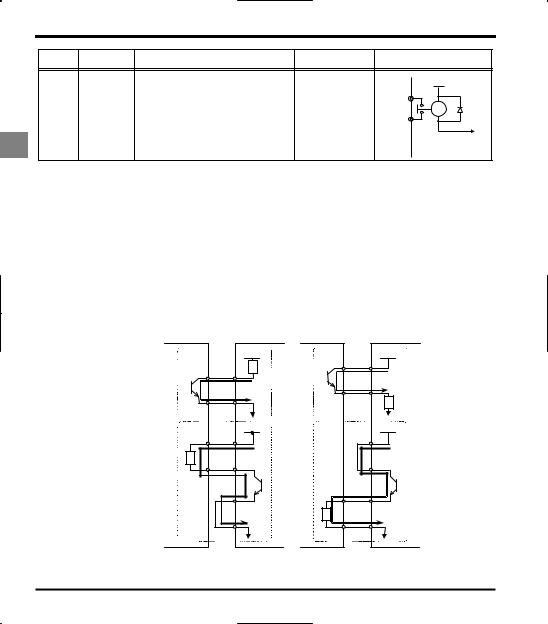
|
|
|
|
E6581160 |
|
Terminal |
Input/output |
Function |
Electrical |
Inverter internal circuits |
|
symbol |
specifications |
||||
|
|
|
|||
|
|
Multifunction programmable relay contact |
|
+24V |
|
|
|
250Vac-1A |
|
||
|
|
output. |
RY |
||
|
|
(cosφ=1) |
|||
|
|
Standard default settings detect and |
|||
RY |
|
: at resistance load |
RY |
||
Output |
output low-speed signal output |
||||
RC |
30Vdc-0.5A |
RC |
|||
|
frequencies. |
||||
|
|
250Vac-0.5A |
|
||
2 |
|
Multifunction output terminals to which two |
|
||
|
(cosφ=0.4) |
|
|||
|
different functions can be assigned. |
|
|||
|
|
|
|||
|
|
|
|
Q SINK (Negative) logic/SOURCE (Positive) logic (When the inverter's internal power supply is used)
Current flowing out turns control input terminals on. These are called sink logic terminals. (Type: -AN/-WN). The general used method in Europe is source logic in which current flowing into the input terminal turns it on (Typ: -WP).
Sink logic is sometimes referred to as negative logic, and source logic is referred to as positive logic. Each logic is supplied with electricity from either the inverter's internal power supply or an external power supply, and its connections vary depending on the power supply used.
Examples of connections when the inverter's internal power supply is used
Slide switch SW1:SINK |
Slide switch SW1:SOURCE |
|||
|
|
|
|
|
Sink (Negative) logic |
|
|
Source (Positive) logic |
|
|
|
|
|
|
|
24VDC |
Input |
|
24VDC |
|
|
|
Common |
P24 |
Input |
|
|
|
|
|
||
Output |
F |
|
|
|
|
|
|
|
Output |
F |
|
Common |
CC |
|
|
|
|
|
24VD |
Output |
|
24VDC |
Output |
Common |
P24 |
|
P24 |
||
|
|
|
|||
Input |
OUT |
|
|
OUT |
|
|
NO |
|
Input |
NO |
|
|
CC |
|
Common CC |
|
|
Programmable |
Inverter |
|
Programmable |
Inverter |
|
controller |
|
|
controller |
|
|
16
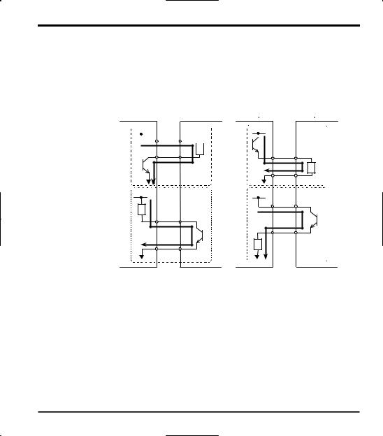
E6581160
QSINK (Negative) logic/SOURCE (Positive) logic (When an external power supply is used)
The PLC terminal is used to connect to an external power supply or to insulate a terminal from other input or output terminals. As for input terminals, turn the SW1 slide switch to the PLC position.
Examples of connections when an external power supply is used
|
|
Slide switch SW1:PLC |
|
|
|
Slide switch SW1:PLC |
|
2 |
||||
|
|
|
|
|
|
|
||||||
|
|
|
|
|
|
|
|
|
|
|
|
|
|
|
Sink (Negative) logic |
|
|
|
|
|
Source (Positive) logic |
|
|
||
|
|
|
|
|||||||||
|
|
|
|
|
|
|
|
|
|
|
|
|
24VDC |
|
Input |
24VDC |
|
|
|||||||
|
|
|
Common PLC |
|
|
|
Input |
|||||
|
|
|
|
|
||||||||
|
|
|
|
|
|
|
|
|
|
|
|
|
Output |
F |
Output |
F |
|
|
Common |
PLC |
24VDC |
|
Output |
24VDC |
Output |
|
|
|
Common |
OUT |
Input |
OUT |
|
|
|
|
|
|
Input |
NO |
Common |
NO |
|
|
|
Programmable |
Inverter |
|
Programmable |
Inverter |
controller |
|
|
controller |
|
QSelecting the functions of the VIA and VIB terminals between analog input and contact input
The functions of the VIA and VIB terminals can be selected between analog input and contact input by changing parameter settings (H). (Factory default setting: Analog input)
When using these terminals as contact input terminals in a sink logic circuit, be sure to insert a resistor between the P24 and VIA terminals or between the P24 and VIB terminals. (Recommended resistance: 4.7KΩ-1/2W)
When using the VIA terminal as a contact input terminal, be sure to turn the VIA switch to the V position. If no resistor is inserted or the VIA slide switch is not turned to the V position, contact input will be left always ON, which is very dangerous.
Switch between analog input and contact input before connecting the terminals to the control circuit terminals. Otherwise the inverter or devices connected to it may be damaged.
17
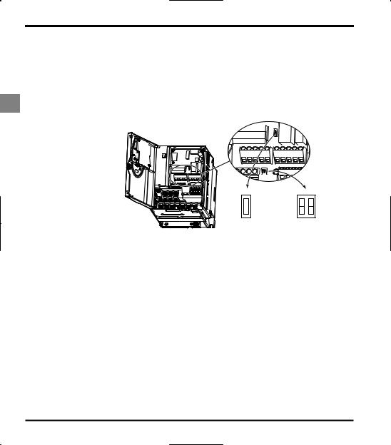
E6581160
QLogic switching/Voltage-current output switching (slide switch)
(1)Logic switching
Use SW1 to switch between logics.
Switch between logics before wiring to the inverter and without supplying power. If switching between sink, source and PLC is done when power is turned on after switching or when the inverter is supplied with power, the inverter might become damaged. Confirm it before supplying power.
(2)Voltage-current output switching
2 |
Use the FM switch to switch between voltage output and current output. |
||||||||||||||||||||||||||||
Switch the FM terminal's voltage-current output before wiring to inverter or without supplying power. |
|||||||||||||||||||||||||||||
|
|
|
|
|
|
|
|
|
|
|
|
|
|
|
|
|
|
|
|
|
|
|
|
|
|
|
|
|
|
|
|
|
|
|
|
|
|
|
|
|
|
|
|
|
|
|
|
|
|
|
|
|
|
|
|
|
|
|
|
|
|
|
|
|
|
|
|
|
|
|
|
|
|
|
|
|
|
|
|
|
|
|
|
|
|
|
|
|
|
|
|
|
|
|
|
|
|
|
|
|
|
|
|
|
|
|
|
|
|
|
|
|
|
|
|
|
|
|
|
|
|
|
|
|
|
|
|
|
|
|
|
|
|
|
|
|
|
|
|
|
|
|
|
|
|
|
|
|
|
|
|
|
|
|
|
|
|
|
|
|
|
|
|
|
|
|
|
|
|
|
|
|
|
|
|
|
|
|
|
|
|
|
|
|
|
|
|
|
|
|
|
|
|
|
|
|
|
|
|
|
|
|
|
|
|
|
|
|
|
|
|
|
|
|
|
|
|
|
|
|
|
|
|
|
|
|
|
|
|
|
|
|
|
|
|
|
|
|
|
|
|
|
|
|
|
|
|
|
|
|
|
|
|
|
|
|
|
|
|
|
|
|
|
|
|
|
|
|
|
|
|
|
|
|
|
|
|
|
|
|
|
|
|
|
|
|
|
|
|
|
|
|
|
|
|
|
|
|
|
|
|
|
|
|
|
|
|
|
|
|
|
|
|
|
|
|
|
|
|
|
|
|
|
|
|
|
|
|
|
SW1
SOURCE
PLC
SINK
Factory default settings of slide switches
SW1 : SINK (Negative) side (WN, AN type)
SOURCE (Positive) side (WP type)
FM : V side
VIA : V side
FM VIA
V 
 V
V
I I
18

E6581160
3. Operations
3.1Simplified Operation of the VF-S11
The procedures for setting operation frequency and the methods of operation can be selected from the following.
Start / Stop |
: |
(1) |
Start and stop using the operation panel keys |
|
|
(2) |
Run and stop from the operation panel |
|
|
|
3 |
|||
|
|
|||
|
: |
(1) |
Setting using the potentiometer on the inverter |
|
Setting the frequency |
|
|||
|
|
main unit |
|
|
|
|
(2) |
Setting using the operation panel |
|
|
|
(3) |
Setting using external signals to the terminal board |
|
|
|
|
(0-10Vdc, 4-20mAdc) |
|
Use the basic parameters EOQF (Operation command mode selection), HOQF (Speed setting mode selection).
Title |
Function |
Adjustment range |
Default setting |
|
EOQF |
Command mode selection |
0: Terminal board |
1 |
|
1: Panel |
||||
|
|
|
||
|
|
0: Internal potentiometer setting |
|
|
|
|
1: VIA |
|
|
|
|
2: VIB |
|
|
HOQF |
Frequency setting mode |
3: Operation panel |
0 |
|
|
|
4: Serial communication |
|
|
|
|
5: External contact up/down |
|
|
|
|
6: VIA+VIB (Override) |
|
*See the manual E6581158 for HOQF=4, 5 and 6.
19
E6581160
3.1.1 How to start and stop
[Example of a EOQF setting procedure]
|
|
Key operated |
LED display |
|
|
|
|
Operation |
|||||||||
|
|
|
|
|
|
|
|
|
|
|
Displays the operation frequency (operation stopped). |
||||||
|
|
|
|
|
|
|
|
|
|
|
(When standard monitor display selection H = [Operation |
||||||
|
|
|
|
|
|
|
|
|
|
|
frequency]) |
||||||
|
|
|
|
|
|
|
|
Displays the first basic parameter [History (CWJ)]. |
|||||||||
|
|
|
|
|
MODE |
|
|
|
|
CWJ |
|||||||
|
|
|
|
|
|
|
|
|
|||||||||
|
|
|
|
|
|
|
|
|
|
|
|
|
|
|
|
|
|
|
|
|
|
|
|
|
|
|
|
|
Press either the |
|
or |
|
key to select “EOQF”. |
||
3 |
|
|
|
|
|
|
|
|
|
EOQF |
|||||||
|
|
|
|
|
|
|
|
|
|
||||||||
|
|
|
|
|
|
|
|
|
|
|
|||||||
|
|
|
|
|
|
|
|
|
|
|
|
|
|
|
|
|
|
|
|
|
|
|
|
|
|
|
|
|
|
|
|
|
|
|
|
|
|
|
|
|
|
|
|
|
|
Press ENTER key to display the parameter setting. (Default setting: ). |
|||||||
|
|
|
|
|
|
|
|
|
|
||||||||
|
|
|
|
|
|
|
|
|
|
|
|
|
|
|
|
|
|
|
|
|
|
|
|
|
|
|
|
|
Change the parameter to (terminal board) by pressing the |
|
key. |
||||
|
|
|
|
|
|
|
|
|
|
|
|||||||
|
|
|
|
|
|
|
|
|
|
|
|||||||
|
|
|
|
|
|
|
|
|
|
|
|
|
|
|
|
|
|
|
|
|
|
|
|
|
|
|
|
|
|
|
|
|
|
|
|
|
|
|
|
|
|
|
|
|
|
EOQF |
Press the ENTER key to save the changed parameter. EOQF and the |
||||||
|
|
|
|
|
|
|
|
|
|
parameter set value are displayed alternately. |
|||||||
|
|
|
|
|
|
|
|
|
|
|
|
|
|
|
|
|
|
(1) Start and stop using the operation panel keys (EOQF= )
Use the  and
and  keys on the operation panel to start and stop the motor.
|
: Motor starts. |
|
: Motor stops. |
|
|
|
|
To switch between forward run and reverse run from the control panel, the parameter fr (forward/reverse run selection) needs to be set to 2 or 3.
(2)RUN/STOP by means of an external signal to the terminal board (EOQF= ): Sink (Negative) logic
Use external signals to the inverter terminal board to start and stop the motor.
Short |
|
and |
CC |
terminals: run forward |
|
Slow down |
|
Frequency |
and stop |
||||||
|
|
|
|
|
|||
Open |
|
and |
|
terminals: slow down and stop |
|
ON |
|
F |
CC |
F-CC |
|||||
OFF |
(3) Coast stop
The standard default setting is for slowdown stop. To make a coast stop, assign a "1(ST)" terminal function to an idle terminal using the programmable terminal function.
Change to H = .
For coast stop, open the ST-CC when stopping the motor in the state described at left.The monitor on the
inverter at this time will display QHH.
Motor |
Coast stop |
|
|
||
speed |
|
|
F-CC |
ON |
|
OFF |
||
|
||
ST-CC |
ON |
|
OFF |
20

|
|
|
|
|
|
|
|
|
|
|
|
|
|
|
E6581160 |
|
|
|
3.1.2 How to set the frequency |
|
|
||||||||||||||||
[Example of a HOQF setting procedure] |
|
|
||||||||||||||||
|
Key operated |
LED display |
|
|
|
|
Operation |
|
|
|||||||||
|
|
|
|
|
|
|
|
|
|
Displays the operation frequency (operation stopped). |
|
|
||||||
|
|
|
|
|
|
|
|
|
|
(When standard monitor display selection H= [Operation |
|
|
||||||
|
|
|
|
|
|
|
|
|
|
frequency]) |
|
|
||||||
|
|
|
|
|
|
|
Displays the first basic parameter [History (CWJ)]. |
|
|
|||||||||
|
|
|
|
MODE |
|
|
|
|
CWJ |
|
|
|||||||
|
|
|
|
|
|
|
|
|
|
|||||||||
|
|
|
|
|
|
|
|
|
|
|
|
|
|
|
|
|
|
|
|
|
|
|
|
|
|
|
|
HOQF |
Press either the |
|
key or |
|
key to select “HOQF”. |
|
|
||
|
|
|
|
|
|
|
|
|
|
|
|
|||||||
|
|
|
|
|
|
|
|
|
|
|
|
|
||||||
|
|
|
|
|
|
|
|
|
|
|
|
|
|
|
|
|
|
3 |
|
|
|
|
|
|
|
|
|
|
|
|
|
|
|
|
|
|
|
|
|
|
|
|
|
|
|
|
|
|
|
|
|
|
|
|
|
|
|
|
|
|
|
|
|
|
|
|
Press ENTER key to display the parameter setting. (Default setting: ). |
|
|||||||
|
|
|
|
|
|
|
|
|
|
|
|
|
|
|
|
|
|
|
|
|
|
|
|
|
|
|
|
|
Change the parameter to (Operation panel) by pressing the |
|
key. |
|
|
||||
|
|
|
|
|
|
|
|
|
|
|
|
|||||||
|
|
|
|
|
|
|
|
|
|
|
|
|||||||
|
|
|
|
|
|
|
|
|
|
|
|
|
|
|
|
|
|
|
|
|
|
|
|
|
|
|
|
|
|
|
|
|
|
|
|
|
|
|
|
|
|
|
|
|
|
|
HOQF |
Press the ENTER key to save the changed parameter. HOQF and the |
|
|
||||||
|
|
|
|
|
|
|
|
|
parameter set value are displayed alternately. |
|
|
|||||||
|
|
|
|
|
|
|
|
|
|
|
|
|
|
|
|
|
|
|
*Pressing the MODE key twice returns the display to standard monitor mode (displaying operation frequency).
(1) Setting the frequency using the potentiometer on the inverter main unit
(HOQF= )
Set the frequency with the notches on the potentiometer.
Move clockwise for the higher frequencies.
The potentiometer has hysteresis. So the set value may slightly change when the inverter is turned off, and then turned back on.
(2) Setting the frequency using the operation panel (HOQF= )
Set the frequency with the operation panel..
 : Moves the frequency up
  : Moves the frequency down
Example of operating a run from the panel
|
Key operated |
LED display |
|
|
|
|
Operation |
|||
|
|
|
|
|
|
Displays the operation frequency. |
||||
|
|
|
|
|
|
(When standard monitor display selection H= [Operation |
||||
|
|
|
|
|
|
frequency]) |
||||
|
|
|
|
|
|
Set the operation frequency. |
||||
|
|
|
|
|
|
|
|
|
|
|
|
|
|
|
|
|
|
|
|
|
|
|
|
|
|
|
HE |
Press the ENT key to save the operation frequency. HE and the |
||||
|
|
|
|
|
frequency are displayed alternately. |
|||||
|
|
|
|
|
|
|
|
|
|
|
|
|
|
|
|
|
Pressing the |
|
key or the |
|
key will change the operation frequency |
|
|
|
|
|
|
|
||||
|
|
|
|
|
|
|
||||
|
|
|
|
|
even during operation. |
|||||
|
|
|
|
|
|
|||||
|
|
|
|
|
|
|
|
|
|
|
21

E6581160
(3) Setting the frequency using the operation panel (HOQF= or )
Frequency setting
1)Setting the frequency using external potentiometer
|
|
|
|
|
|
|
|
|
Potentiometer |
|
|
|
|
|
|
|
|
|
PP |
: Setting frequency |
Setting frequency using the potentiometer (1-10kΩ, 1/4W) |
||
|
|
|
|
|
|
|
|||||
|
|
|
|
|
|
|
|
|
|
|
|
|
|
|
|
|
|
|
VIB |
60Hz |
|
|
|
|
|
|
|
|
|
|
|
|
|||
|
|
|
|
|
|
|
|
using potentiometer |
|
|
|
|
|
|
|
|
|
|
|
|
|
|
|
3 |
|
|
|
|
|
|
|
|
Frequency |
|
|
|
|
|
|
|
|
CC |
|
0 |
|
MAX |
|
|
|
|
|
|
|
|
|
||||
|
|
|
|
|
|
|
|
|
|||
|
|
|
|
|
|
|
|
|
|||
|
|
|
|
|
|
|
|
|
MIN |
||
* |
|
The input terminal VIA can be used in the same way. |
|
|
|
||||||
|
|
|
|
HOQF= : VIA effective, HOQF= : VIB effective |
|
|
|
||||
2)Setting the frequency using input voltage (0~10V)
|
|
|
|
|
Voltage signal |
|
+ |
|
|
VIA |
: Voltage signal 0-10mAdc |
Setting frequency using voltage signals (0 10V). |
|
|
|
|||||
|
|
|
|
60Hz |
|
|
|
|
|
|
|
||
- |
|
|
CC |
|
|
|
|
|
|
Frequency |
|
||
|
|
|
|
|||
|
|
|
|
|
|
|
|
|
|
|
|
|
|
|
|
|
|
|
0 |
10Vdc |
|
|
|
|
|
0Vdc |
|
* |
The input terminal VIB can be used in the same way. |
|
|
|||
HOQF= : VIA effective, HOQF= : VIB effective |
|
|
||||
Note: Be sure to turn the VIA slide switch to the V (voltage) position.
3)Setting the frequency using current input (4~20mA)
Current Signal
Current signal Setting frequency using current signals (4~20mA).
+ |
|
|
VIA |
: Current signal 4-20mAdc |
60Hz |
|
|
||||
|
|
|
|
||
|
|
|
|
||
- |
|
|
CC |
|
Frequency |
|
|
|
|||
|
|
|
|
|
0 |
4mAdc |
20mAdc |
|
* Setting of parameters also allow 0-20mAdc.
Note: Be sure to turn the VIA slide switch to the I (current) position.
22
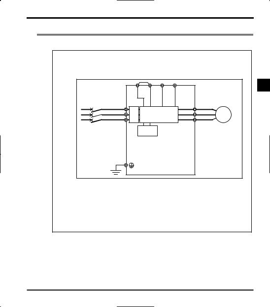
E6581160
3.2How to operate the VF-S11
Overview of how to operate the inverter with simple examples.
Ex.1 |
Setting the operation frequency using built-in potentiometer and |
running and stopping using the operation panel. |
|
|
|
(1) |
Wiring |
|
|
|
|
|
|
|
|
|
|
PO |
PA/+ |
PB |
PC/- |
|
3 |
|
MCCB |
R/L1 |
|
|
|
|
U/T1 |
Motor |
|
|
|
|
|
|
|||
|
|
|
|
|
|
|
||
|
|
S/L2 |
Noise* |
Power circuit |
V/T2 |
IM |
||
|
|
T/L3 |
filter |
W/T3 |
||||
|
|
|
|
|
|
|||
|
|
|
|
Braking |
|
|
|
|
|
|
|
|
circuit |
|
|
|
|
Parameter setting (default setting)
Title |
Function |
Programmed value |
EOQF |
Command mode selection |
1 |
HOQF |
Frequency setting mode selection 1 |
0 |
(3)Operation
Run/stop: Press the  and
and  keys on the panel.
Frequency setting: Set adjusting position of notches on the potentiometer.
*600V models have no noise filter inside.
23
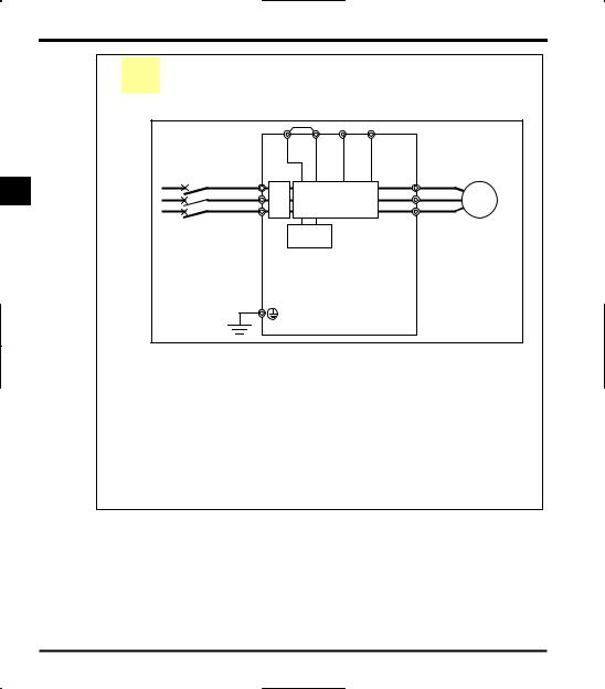
|
|
|
|
|
|
|
|
|
E6581160 |
Ex.2 |
Setting the operation frequency using the operation panel and |
||||||||
running and stopping using the operation panel. |
|
||||||||
(1) |
Wiring |
|
|
|
|
|
|
|
|
|
|
|
|
PO |
PA/+ |
PB |
PC/- |
|
|
3 |
|
MCCB |
R/L1 |
|
|
|
|
U/T1 |
Motor |
|
|
|
|
|
|
||||
|
|
|
|
|
|
|
|||
|
|
S/L2 |
Noise* |
Power circuit |
V/T2 |
IM |
|||
|
|
|
T/L3 |
filter |
|
|
|
W/T3 |
|
|
|
|
|
|
Braking |
|
|
|
|
|
|
|
|
|
circuit |
|
|
|
|
(2)Parameter setting
Title |
Function |
Programmed value |
EOQF |
Command mode selection |
1 |
HOQF |
Frequency setting mode selection 1 |
3 |
(3)Operation
Run/stop: Press the  and
and  keys on the panel.
Frequency setting: Set with the  keys on the operation panel.
To store the set frequencies in memory, press the  key.
key.
HEand the set frequency will flash on and off alternately.
* 600V models have no noise filter inside.
24
Loading...