


TLRE50T
TOSHIBA TLRE50T, TLRME50T, TLSE50T, TLOE50T, TLYE50T Technical data
...
TL(RE,RME,SE,OE,YE,PYE,GE,FGE,PGE)50T
2002-01-17
1
TOSHIBA InGaAℓP LED
TLRE50T,TLRME50T,TLSE50T,TLOE50T,TLYE50T,
TLPYE50T,TLGE50T,TLFGE50T,TLPGE50T
Panel Circuit Indicators
· φ3 mm package
· InGaAℓP technology
· All plastic mold type
· Transparent lens
· Line-up: 6 colors (red, orange, yellow, pure yellow, green and pure
green)
· High intensity light emission
· Excellent low current light output
· Applications: message boards, security devices and dashboard
displays
Line-up
Unit: mm
JEDEC ―
JEITA ―
TOSHIBA 4-3E1A
Weight: 0.14 g
Product Name Color Material
TLRE50T Red
TLRME50T Red
TLSE50T Red
TLOE50T Orange
TLYE50T Yellow
TLPYE50T Pure Yellow
TLGE50T Green
TLFGE50T Green
TLPGE50T Pure Green
PInGaAl
查询TLFGE50T供应商
TL(RE,RME,SE,OE,YE,PYE,GE,FGE,PGE)50T
2002-01-17
2
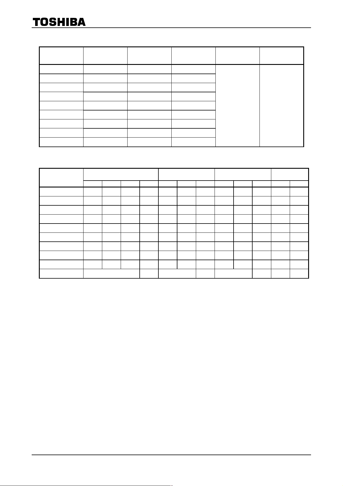
Maximum Ratings
(Ta =
==
= 25°C)
Product Name
Forward Current
I
F
(mA)
Reverse Voltage
V
R
(V)
Power Dissipation
P
D
(mW)
Operating
Temperature
T
opr
(°C)
Storage
Temperature
T
stg
(°C)
TLRE50T 50 4 120
TLRME50T 50 4 120
TLSE50T 50 4 120
TLOE50T 50 4 120
TLYE50T 50 4 120
TLPYE50T 50 4 120
TLGE50T 50 4 120
TLFGE50T 50 4 120
TLPGE50T 50 4 120
-40~100 -40~120
Electrical and Optical Characteristics
(Ta =
==
= 25°C)
Typ. Emission Wavelength
Luminous Intensity
I
V
Forward Voltage
V
F
Reverse Current
I
R
Product Name
l
d
l
P
Dl I
F
Min Typ. I
F
Typ. Max I
F
Max V
R
TLRE50T 630 (644) 20 20 850 1800 20 1.9 2.4 20 50 4
TLRME50T 626 (636) 23 20 850 2200 20 1.9 2.4 20 50 4
TLSE50T 613 (623) 20 20 1530 3500 20 1.9 2.4 20 50 4
TLOE50T 605 (612) 20 20 1530 4500 20 2.0 2.4 20 50 4
TLYE50T 587 (590) 17 20 1530 3500 20 2.0 2.4 20 50 4
TLPYE50T 580 (583) 14 20 850 2500 20 2.0 2.4 20 50 4
TLGE50T 571 (574) 17 20 476 1500 20 2.0 2.4 20 50 4
TLFGE50T 565 (568) 15 20 272 1000 20 2.0 2.4 20 50 4
TLPGE50T 558 (562) 14 20 153 600 20 2.1 2.4 20 50 4
Unit nm mA mcd mA V mA mA V
Precautions
Please be careful of the following:
· Soldering temperature: 260°C max, soldering time: 3 s max
(soldering portion of lead: up to 2 mm from the body of the device)
· If the lead is formed, the lead should be formed up to 5 mm from the body of the device without forming stress to
the resin. Soldering should be performed after lead forming.
· This visible LED lamp also emits some IR light.
If a photodetector is located near the LED lamp, please ensure that it will not be affected by this IR light.
TL(RE,RME,SE,OE,YE,PYE,GE,FGE,PGE)50T
2002-01-17
3
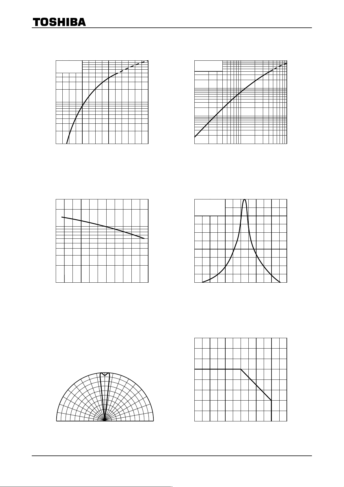
TLRE50T
20
-20 80
0.1
3
1
0.3
0.5
0
40
60
700
0.8
0
0.6
1.0
0.2
0.4
I
F
= 20 mA
Ta = 25°C
680 660 640 620600580
101
100
10000
1000
Ta = 25°C
100
10
0
60
0
40
80
20
12020
40 60 80
100
1.6
50
30
10
3
1
5
100
Ta = 25°C
1.7 1.8 1.9 2.0 2.1 2.2 2.3
Relative luminous intensity
Forward voltage V
F
(V)
I
F
– V
F
Forward current I
F
(mA)
Forward current I
F
(mA)
I
V
– I
F
Luminous intensity I
V
(mcd)
Case temperature Tc (°C)
I
V
– Tc
Relative luminous intensity I
V
Wavelength l (nm)
Relative luminous intensity – Wavelength
Ambient temperature Ta (°C)
I
F
– Ta
Allowable forward current I
F
(mA)
Radiation pattern
Ta = 25°C
30°
0°
60°
90°
90°
30°
60°
1.00.80.6 0.4 0.2 0
80°
70°
50°
40°
20°
10°
70°
80°
50°
40°
20°
10°
TL(RE,RME,SE,OE,YE,PYE,GE,FGE,PGE)50T
2002-01-17
4
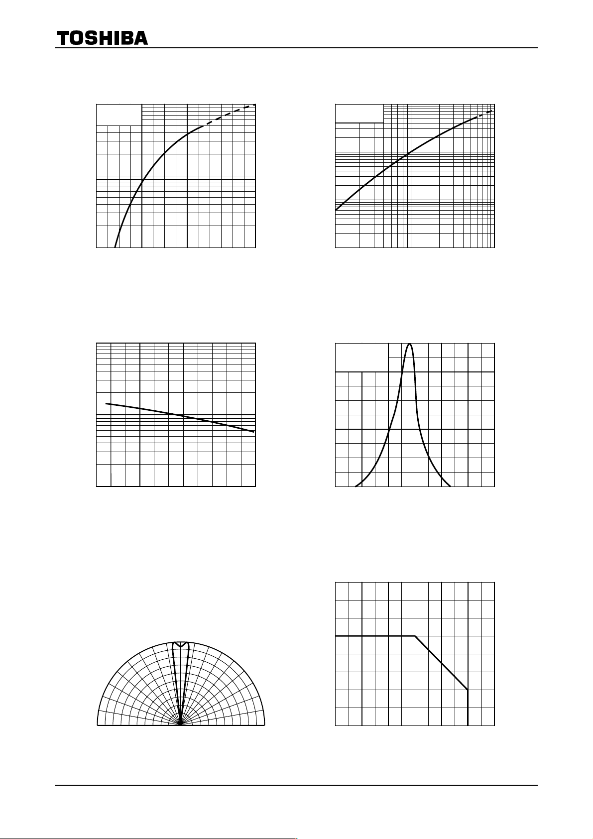
TLRME50T
1.6
50
30
10
3
1
5
100
Ta = 25°C
1.7 1.8 1.9 2.0 2.1 2.2 2.3
700
0.8
0
0.6
1.0
0.2
0.4
I
F
= 20 mA
Ta = 25°C
680 660 640 620600580
Relative luminous intensity
Forward voltage V
F
(V)
I
F
– V
F
Forward current I
F
(mA)
Forward current I
F
(mA)
I
V
– I
F
Luminous intensity I
V
(mcd)
Case temperature Tc (°C)
I
V
– Tc
Relative luminous intensity I
V
Wavelength l (nm)
Relative luminous intensity – Wavelength
Ambient temperature Ta (°C)
I
F
– Ta
Allowable forward current I
F
(mA)
Radiation pattern
Ta = 25°C
30°
0°
60°
90°
90°
30°
60°
1.00.80.6 0.4 0.2 0
80°
70°
50°
40°
20°
10°
70°
80°
50°
40°
20°
10°
101
100
10000
1000
Ta = 25°C
100
10
0
60
0
40
80
20
12020
40 60 80
100
20
-20 80
0.1
3
1
0.3
0.5
0
40
60
5
10
 Loading...