


RAS-10PKVP-E
Table of contents
 Loading...
Toshiba RAS-10PKVP-E, RAS-07PAVP-E, RAS-13PAVP-E, RAS-13PKVP-E, RAS-10PAVP-E Manual
...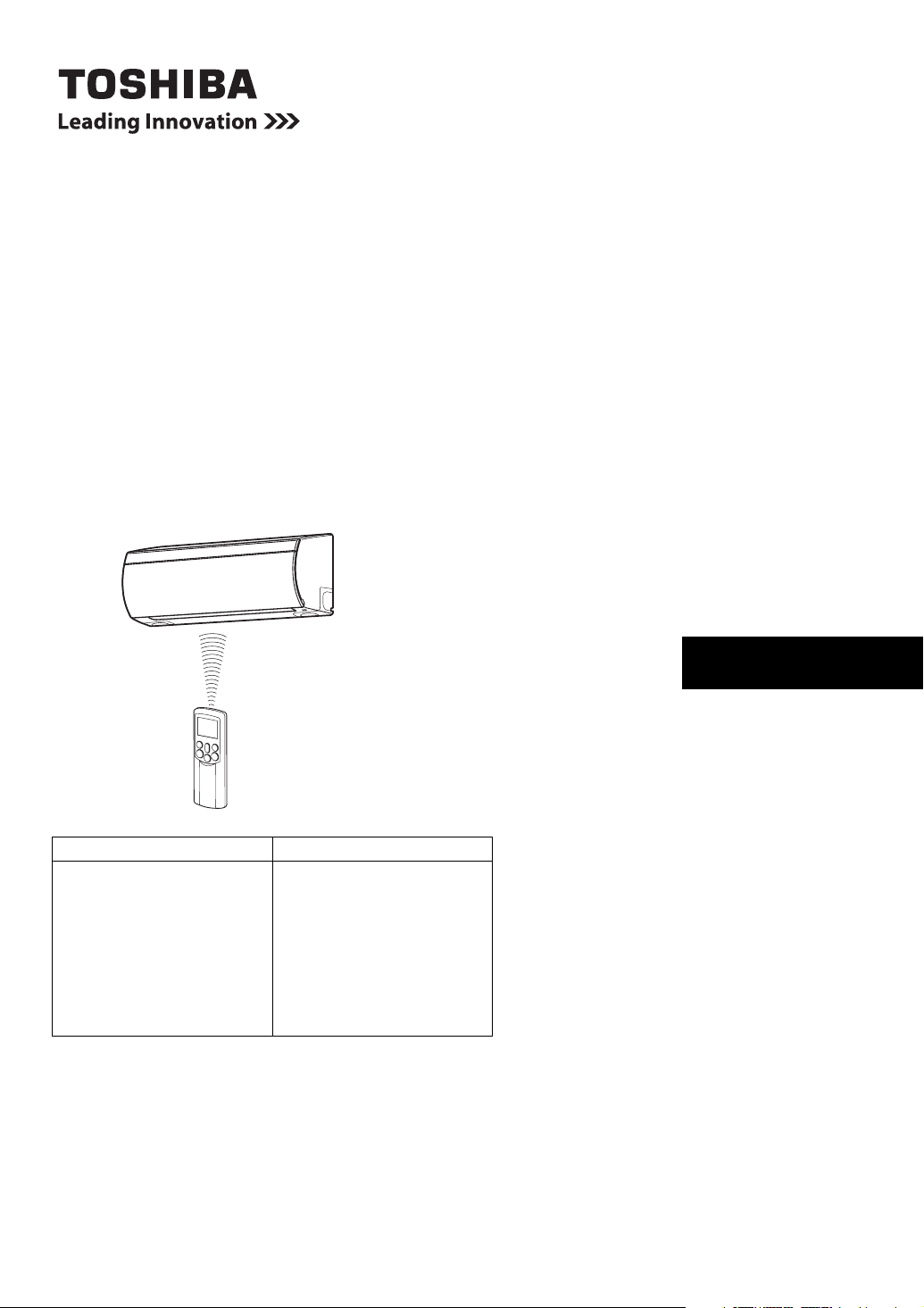
OWNER’S MANUAL
AIR CONDITIONER (SPLIT TYPE)
For general public use
Indoor Unit Outdoor Unit
RAS-07PKVP-E
RAS-10PKVP-E
RAS-13PKVP-E
RAS-16PKVP-E
RAS-18PKVP-E
RAS-07PKVP-ND
RAS-10PKVP-ND
RAS-13PKVP-ND
RAS-16PKVP-ND
RAS-18PKVP-ND
RAS-07PAVP-E
RAS-10PAVP-E
RAS-13PAVP-E
RAS-16PAVP-E
RAS-18PAVP-E
RAS-07PAVP-ND
RAS-10PAVP-ND
RAS-13PAVP-ND
RAS-16PAVP-ND
RAS-18PAVP-ND
ENGLISH EN
CONTENTS
ENGLISH
ACCESSORIES.............................................................................. 1
PRECAUTION FOR SAFETY ........................................................ 1
NAMES OF PARTS........................................................................ 4
NAMES AND FUNCTIONS OF INDICATORS AND CONTROLS
ON INDOOR UNIT ....................................................................... 4
REMOTE CONTROLLER AND ITS FUNCTIONS.......................... 5
NAMES AND FUNCTIONS OF INDICATORS ON REMOTE
CONTROLLER............................................................................. 6
PREPARATION AND CHECK BEFORE USE ............................... 7
USING THE REMOTE CONTROLLER .......................................... 9
AUTOMATIC OPERATION .......................................................... 10
AUTOMATIC OPERATION (AUTO CHANGEOVER) .................. 10
COOLING/HEATING OPERATION .............................................. 11
DRY OPERATION........................................................................ 11
8°C OPERATION (RAS-***-ND model only) ................................ 12
PURE OPERATION ..................................................................... 13
Hi POWER OPERATION ............................................................. 13
TIMER OPERATION..................................................................... 14
MEMORY/MY COMFORT OPERATION ...................................... 16
ADJUSTING AIR FLOW DIRECTION........................................... 17
AUTO RESTART OPERATION .................................................... 18
HOW THE AIR CONDITIONER WORKS ..................................... 19
TEMPORARY OPERATION ......................................................... 20
CLEANING OPERATION.............................................................. 20
USUAL MAINTENANCE ............................................................... 21
AIR CONDITIONER OPERATION AND PERFORMANCE ..........23
TROUBLESHOOTING .................................................................. 24
TROUBLESHOOTING (Remote Controller) ................................. 27
SPECIFICATIONS ........................................................................ 28
* Thank you for purchasing this TOSHIBA Air Conditioner.
Please read this owner’s manual carefully before using
your Air Conditioner.
i

ACCESSORIES
Remote controller Remote controller holder Batteries (two)
PRECAUTION FOR SAFETY
Store this owner’s manual in a location where it can be easily accessed when needed.
Be sure to read this owner’s manual carefully before operating.
The supplied CD-ROM contains the owner’s manual translated into many languages.
It is recommended that maintenance be performed by a specialist when the unit has been operated for a long time.
Be sure to follow the precautions provided here to avoid safety risks.
DANGER
WARNING
CAUTION
*1: A severe injury refers to blindness, injury, burns (hot or cold), electrical shock, bone fracture, or poisoning that leaves aftereffects
and requires hospitalization or extended out-patient treatment.
*2: Personal injury means a slight accident, burn, or electrical shock which does not require admission or repeated hospital treatment.
*3: Property damage means greater damage which affects assets or resources.
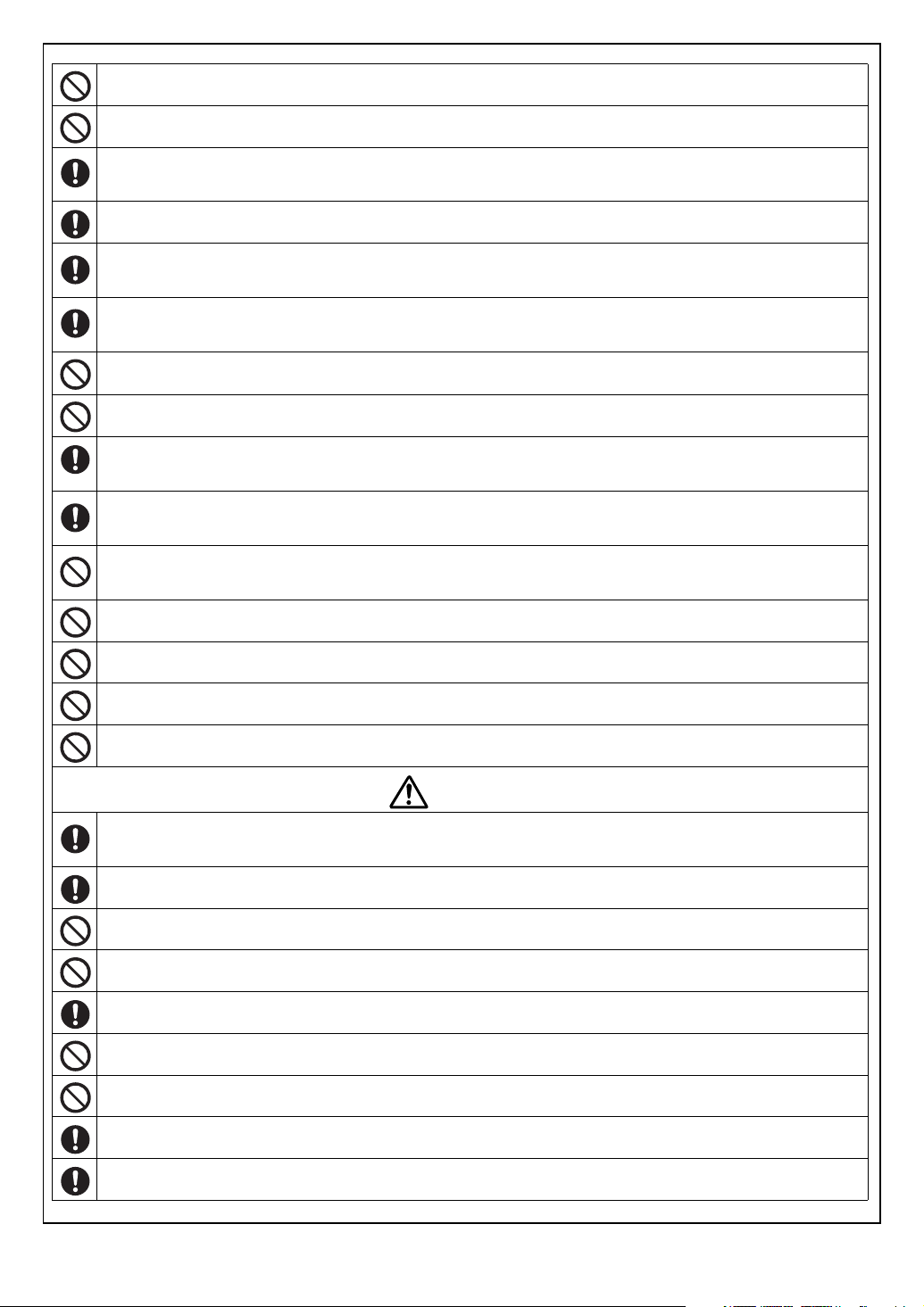
Never do. Beware of rotating parts
Electrical hazard. Contact with water will cause electric
shock. Do NOT touch with wet hands. Always unplug
when not in use.
Always follow the instructions Do not get the product wet
The symbols and their meanings are shown below.
It indicates that incorrect use of this unit can result in a high possibility of severe injury(*1)
or death.
It indicates that incorrect use of this unit may cause severe injury or death.
It indicates that incorrect use of this unit may cause personal injury(*2), or property
damage(*3).
Risk of finger injury
DANGER
Do not install, repair, open or remove the cover. It may expose you to dangerous voltages. Ask the dealership or the
specialist to do this.
Turning off the power supply will not prevent potential electric shock.
WARNING
The appliance shall be installed in accordance with national wiring regulation.
Means for disconnection from the supply having a contact separation of at least 3 mm in all poles must be incorporated in
the fixed wiring.
Installation must be requested from the supplying retail dealership or professional installation vendors. Installation requires
special knowledge and skill. If customers install on their own, it can be a cause of fire, electric shock, injury or water
leakage.
Do not disassemble, modify or relocate the unit by yourself. It may become the cause of fire, electric shock, or water
leakage. For repair or relocation, please request service from the supplying retail dealership or a dealership.
When relocating or repairing the unit, please contact the supplying retail dealership. When there is a kink in the wiring, it
may be the cause of electric shock or fire.
1 EN
Do not select a location for installation where flammable gas may leak. If there is any gas leakage or accumulation around
the unit, it can be a cause of fire.
Do not select a location for installation where there may be excessive water or humidity, such as a bathroom. Deterioration
of insulation may be a cause of electric shock or fire.
Earth work should be requested from the supplying retail dealership or professional vendors. Insufficient grounding work
may be the cause of electric shock. Do not connect the earth wire to a gas pipe, water pipe, lightning conductor, or
telephone earth wire.
You must use an independent power outlet for the power supply. If a power outlet other than the independent outlet is used,
it may cause a fire.
Check that the circuit breaker is installed correctly. If the circuit breaker is not properly installed, it may cause an electric
shock. To check the installation method, please contact the supplying retail dealership or the professional vendor who
installed the unit.
During an error (such as a burning odor, not cooling, or not warming), stop operating the unit and turn off the circuit breaker.
Continuous operation may be a cause of fire, or electric shock. Please request repair or service from the supplying retail
dealership.
Do not turn ON/OFF the circuit breaker or operate buttons with a wet hand. It may be a cause of electric shock.
Do not insert any material (metal, paper, or water, etc) into the air outlet or air intake opening. Fan may be rotating at high
speed inside or there are high voltage sections, which may cause an injury or electric shock.
When the air-conditioning unit does not cool or warm, there may be a leakage of refrigerant. Please consult the supplying
retail dealership. The refrigerant used in the air-conditioning unit is safe. It will not leak under normal operating conditions
but if it leaks into the room and contacts a heat source such as a heater, or stove, it may cause a harmful reaction.
When water or other foreign substances enter the internal parts, stop operating the unit immediately and turn off the circuit
breaker. Operating the unit continuously may cause fire or electric shock. Please contact the supplying retail dealership for
repair.
Do not clean the inside of the air-conditioning unit yourself. Please request internal cleaning of the air-conditioning unit from
the supplying retail dealership. Incorrect cleaning may cause breakage of resin parts or insulation defects of electrical parts,
causing water leakage, electric shock or fire.
Do not damage or modify the power cable. Do not connect the cable midway, or use a multiple outlet extension cord that is
shared by other devices. Failure to do so may cause fire.
Do not place heavy objects on the power cable, expose it to heat, or pull it. To do so may cause electrical shock or fire.
Do not expose your body directly to cool air for a long time.
Do not insert your finger or any article into the air inlet/outlet.
CAUTION
Ensure that drained water is discharged. When the discharging water process is not sufficient, water may leak, causing
water damage to furniture. To check that the installation method used is correct, please contact the supplying retail
dealership or the professional vendor who installed the unit.
If the indoor unit piping outlet is exposed due to relocation, close the opening, Touching internal electrical parts may cause
injury or electric shock.
Do not wash the main air-conditioning unit with water. It may cause an electric shock.
Do not place any containers such as a vase containing fluid on the unit. It might cause water to enter the unit and deteriorate
the electrical insulation, causing an electric shock.
When using the unit in a closed room, or operating with other combustion appliances, make sure to open a window
occasionally for ventilation. Insufficient ventilation may cause suffocation due to a lack of oxygen.
Do not use combustion appliances in the direct flow of the air from the air-conditioning unit. Poor combustion of a
combustion appliance may cause suffocation.
Avoid operating for long periods in a high humidity environment (over 80%) such as with the windows or doors open. There
may be condensation on the indoor unit and droplets may fall onto the furniture.
When the unit won’t be used for a long time, turn off the main switch or the circuit breaker.
At least once a year check if the mounting table of the outdoor unit is damaged or not. If a damaged state is ignored, the unit
may fall or over-turn, causing an injury.
EN
2
Stand on a sturdy ladder when attaching/detaching the front panel/air filter/air cleaning filter. Failure to do so may cause a
fall or injury.
Do not stand on the outdoor unit or place anything on the unit. It may be the cause of injury due to falling or over-turning.
Any damage to the unit may cause an electric shock or fire.
Do not place anything around the outdoor unit or allow fallen leaves to accumulate around it. If there are fallen leaves, small
animals could enter and contact internal electrical par ts, causing a failure or fire.
Do not place animals and plants in places where wind from the air-conditioning unit flows directly. It may have a negative
influence on the animal or plant.
Do not use for special applications such as storage of food or animals, or to display plants, precision devices, or art objects.
Do not use on ships or in other vehicles. It may cause a failure in the air-conditioning unit. In addition, it may damage these
items.
Do not place other electrical appliances or furniture under the unit. Water droplets might fall, causing damage or failure.
When performing maintenance, you must stop operating the unit and turn off the circuit breaker. Since the fan inside may be
rotating at high speed, it may cause an injury.
After the front panel/air filter is cleaned, wipe away any water and allow to dry. If water remains, it may cause an electric
shock.
Once the front panel is removed, do not touch the metal parts (aluminum fins, etc.) of the unit. It may cause an injury.
When you hear thunder and there might be a lightning strike, stop operating the unit and disconnect the circuit breaker. If
lightning strikes, it may cause a failure.
Do not hang laundry or other objects from the moving panel. The moving panel could fall and cause an injury.
3 EN

NAMES OF PARTS
Outdoor unit
a Refrigerant connecting pipe, electric wires and drain
hose
b Air inlet
c Air outlet
Indoor unit
d Humidity sensor/temperature sensor
e Front panel
f Moving panel
g Air filter
h Air outlet
i Horizontal air flow louver
j Vertical air flow louver
k Plasma ion charger
l Display panel
m Infrared signal receiver
n Remote controller
o Panel support
b
a
c
egfod
n
ihklmj
CAUTION
Use care to avoid burns. A heater is installed on the base plate of the outdoor unit. When the outside air temperature is low, the
heater runs to warm the base plate even if the unit is not operating so that snow does not accumulate inside the outdoor unit.
(RAS-***-ND model only)
NAMES AND FUNCTIONS OF INDICATORS AND CONTROLS ON INDOOR UNIT
Display panel
The operating states are shown below.
a RESET button
b OPERATION indicator (Green)
c TIMER/S.CLEAN indicator (Orange)
d PURE indicator (Blue) *1
e Infrared signal reciever
*1: If the orange light of the PURE indicator is turned on, this
indicates a problem in the plasma ion charger. Please
contact the dealer where you made the purchase.
RESET button
The RESET button has the following function.
• Temporary operation function
Use when you misplace or lose the remote controller, or when its
batteries are used up. () see page 20.)
b
c
d
e
a
EN
4
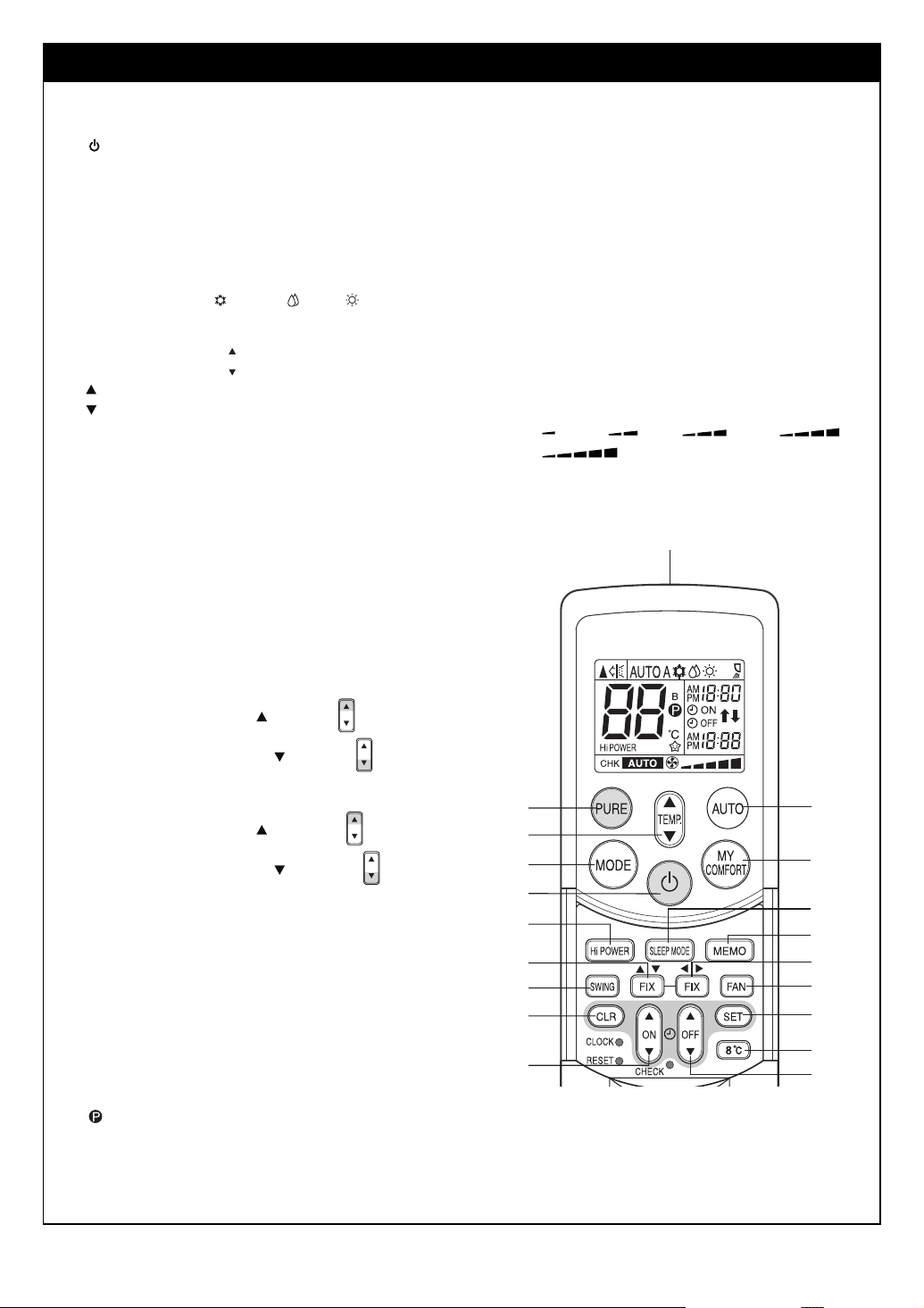
REMOTE CONTROLLER AND ITS FUNCTIONS
a Infrared signal transmitter
Transmits signals to the indoor unit.
b button
Press the button to start operation. (A receiving beep is
heard.) Press the button again to stop operation. (A
receiving beep is heard.)
If no receiving sound is heard from the indoor unit, press
the button again.
c Mode select button (MODE)
Press this button to select a mode. Each time you press
the button, the modes cycle in order from A: Auto
changeover control, : COOL, : DRY, : HEAT and
back to A.
(A receiving beep is heard.)
d Temperature button ( )
.. The temperature setting is raised to 30°C.
... The temperature setting is lowered to 17°C.
(A receiving beep is heard.)
e Set horizontal air flow button (FIX)
Press this button to adjust the horizontal air flow direction.
(A receiving beep is heard.) () see page 17.)
f Set vertical air flow button (FIX)
Press this button to adjust the vertical air flow direction. (A
receiving beep is heard.) () see page 17.)
g Auto louver button (SWING)
Each time you press the SWING button, you can change
the swing mode. (A receiving beep is heard.)
(Vertical swing
Horizontal swing
Press the button again to stop the swinging mode. (A
receiving beep is heard.) () see page 17.)
h ON timer button (ON)
Use this button to change the clock and ON timer times.
To move up the time, press of the ON button.
TEMP
—> Horizontal swing —> Vertical and
—> Stop swinging)
ON
n Automatic operation button (AUTO)
Press this button to operate the air conditioner
automatically.
(A receiving beep is heard.) () see page 10.)
o SLEEP MODE button
Press this button to start sleep mode. () see page 19.)
p MY COMFORT button
Press this button to operate the air conditioner according to
the settings stored using the MEMO button. () see
page 16.)
q PURE button (PURE)
Press this button to start the electrical air purifying
operation.
Press the button again to stop operation. () see page 13.)
r Fan speed button (FAN)
Press this button to select the fan speed. When you select
AUTO, the fan speed is automatically adjusted according to
the room temperature. You can also manually select the
desired fan speed from five available settings.
(LOW , LOW+ , MED , MED+ ,
HIGH ) (A receiving beep is heard.)
s 8°C operation button (8°C)
Press this button to start the 8°C set temperature heating
operation. () see page 12.) (RAS-***-ND model only)
a
To move down the time, press of the ON button.
i OFF timer button (OFF)
Use this button to change the OFF timer times.
To move up the time, press of the OFF button.
To move down the time, press of the OFF button.
j Reserve button (SET)
Press this button to store the time settings. (A receiving
beep is heard.)
k Cancel button (CLR)
Press this button to cancel the ON timer and OFF timer. (A
receiving beep is heard.)
l High power button (Hi POWER)
Press this button to start high power operation. () see
page 19.)
m Memory button (MEMO)
Press this button to ready for storing the settings.
Hold down the button for 3 seconds or more to store the
setting indicated on the remote controller and until the
mark is displayed. () see page 16.)
ON
OFF
OFF
q
n
d
c
p
b
l
f
g
k
o
m
e
r
j
s
h
i
5 EN
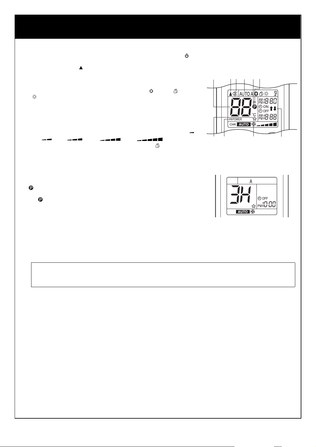
NAMES AND FUNCTIONS OF INDICATORS ON REMOTE CONTROLLER
Display
All indicators, except for the clock time indicator, are displayed by pressing the button.
a Transmission mark
This transmission mark ( ) indicates when the remote controller transmits signals to the indoor unit.
b Mode indicator
Indicates the current operation mode.
• Heat pump models
(AUTO: Automatic control, A: Auto changeover control, : COOL, : DRY,
:HEAT)
c Temperature indicator
Indicates the temperature setting (17°C to 30°C).
d PURE indicator
Shows that the electrical air purifying operation is in progress.
e FAN speed indicator
Indicates the selected fan speed. AUTO or one of five fan speed levels (LOW ,
LOW+ , MED , MED+ , HIGH ) can be shown.
Indicates AUTO when the operating mode is either AUTO or : DRY.
f TIMER and clock time indicator
The time setting for timer operation or the clock time is indicated.
The current time is always indicated except during TIMER operation.
g Hi POWER indicator
Indicates when Hi POWER operation starts.
Press the Hi POWER button to start and press it again to stop operation.
h (MEMORY) indicator
Flashes for 3 seconds when the MEMO button is pressed during operation.
The mark is shown when holding down the button for 3 seconds or more while
the mark is flashing.
Press another button to turn off the mark.
i SLEEP MODE indicator
Indicates when the SLEEP MODE is activated.
Press the SLEEP MODE button to start and press it again to stop operation.
j A. B change indicator remote controller
• When the remote controller switching function is set, “B” appears in the remote
controller display. (When the remote controller setting is “A”, there is no
indication at this position.)
Remote controller switching function
• If two indoor units are installed in the same room or adjoining rooms, both units may start and stop at the same time when
the remote controller is operated. This can be prevented by setting the switching function so that each indoor unit is
operated only by the corresponding remote controller.
• To use the remote controller switching function, contact the air conditioner dealer or the installation company.
cabhjd
gi
• In the illustration, all indicators are shown
for purposes of explanation. During
operation, only the relevant indicators are
shown on the remote controller.
e
f
EN
6
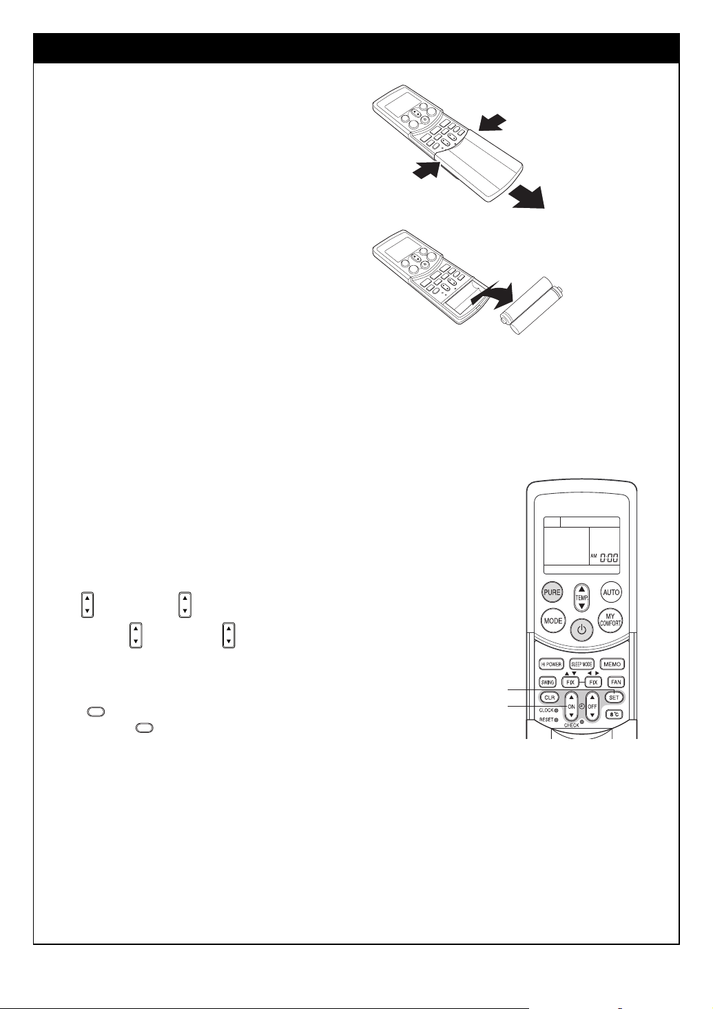
PREPARATION AND CHECK BEFORE USE
Loading the remote controller batteries
a Remove the cover, and insert the batteries.
b Reattach the cover.
Removing the batteries
a Remove the cover, and take out the batteries.
b Reattach the cover.
* Please dispose of the batteries according to the local
regulation.
Batteries
• To replace the batteries, use two new batteries (AAA type).
• The batteries will last about one year under normal usage.
• Replace the batteries if there is no receiving beep from the indoor unit or when the air conditioner cannot be operated using the
remote controller.
• To avoid malfunctions due to battery leakage, remove the batteries when not using the remote controller for over one month.
• Slide off the cover while pressing the sides.
• Battery replacement
Be careful not to reverse the (+) position and the (–) position.
Setting the clock
Before you start operating the air conditioner, set the clock of the remote controller using
the procedures given in this section. The clock panel on the remote controller will
indicate the time regardless of whether the air conditioner is in use or not.
Initial setting
When batteries are inserted in the remote controller, the clock panel displays AM 0:00
and flashes.
a ON button (or OFF button)
ON
Press the ON button (or OFF button) to set the current time.
ON
Each press of the ON button (or OFF button) changes the time in one minute
increments.
Holding down the ON button (or OFF button) changes the time in ten minute
increments.
b SET button
SET
Press the SET button.
The current time is displayed and the clock starts.
OFF
OFF
SET
b
a
7 EN

Adjusting the clock
a CLOCK button
Press the CLOCK button.
The clock time indicator flashes.
b ON button (or OFF button)
ON
OFF
Press the ON button (or OFF button) to set
ON
OFF
the current time.
Each press of the ON button (or OFF button)
changes the time in one minute increments.
Holding down the ON button (or OFF button)
changes the time in ten minute increments.
c SET button
SET
Press the SET button.
SET
The current time is displayed and the clock starts.
Push CLOCK
b
a
c
EN
8
Loading...