


T O S H I B AF I L E N O . A
S E R V I C E M A N
A I R - C O
S P L I T
RA S - 1R0ASSK-H1
RA S - 1R0ASSK-H1
P R I N T E D I N J A P
|
|
CONTENTS |
|
1. SPECIFICATIONS ............................................................................................................ |
4 |
||
2. CONSTRUCTION VIEWS ................................................................................................ |
6 |
||
2-1. |
Indoor Unit .................................................................................................................................. |
6 |
|
2-2. |
Outdoor Unit ............................................................................................................................... |
7 |
|
3. WIRING DIAGRAM .......................................................................................................... |
8 |
||
4. SPECIFICATIONS OF ELECTRICAL PARTS ................................................................. |
9 |
||
4-1. |
Indoor Unit .................................................................................................................................. |
9 |
|
4-2. |
Outdoor Unit ............................................................................................................................... |
9 |
|
5. REFRIGERANT CYCLE DIAGRAM .............................................................................. |
10 |
||
6. MICRO-COMPUTER BLOCK DIAGRAM ....................................................................... |
11 |
||
7. OPERATION DESCRIPTIONS ....................................................................................... |
12 |
||
7-1. |
FAN ONLY Operation ............................................................................................................... |
12 |
|
7-2. |
COOL Operation ....................................................................................................................... |
12 |
|
|
7-2-1. |
Louver Control ...................................................................................................................................... |
13 |
7-3. |
DRY Operation .......................................................................................................................... |
13 |
|
7-4. |
HEAT Operation ........................................................................................................................ |
14 |
|
|
7-4-1. |
Louver Control ...................................................................................................................................... |
14 |
|
7-4-2. |
Cool Airflow Control ............................................................................................................................. |
14 |
7-5. |
AUTO Operation ....................................................................................................................... |
15 |
|
|
7-5-1. |
Temporary Auto ..................................................................................................................................... |
15 |
7-6. |
ECONO. Mode ........................................................................................................................... |
16 |
|
|
7-6-1. Cooling ................................................................................................................................................... |
16 |
|
|
7-6-2. Heating ................................................................................................................................................... |
16 |
|
7-7. |
Current Limit Control ............................................................................................................... |
16 |
|
7-8. |
High-Temperature Limit Control (Heating Operation) .......................................................... |
17 |
|
7-9. |
Low-Temperature Limit Control (Cooling Operation) .......................................................... |
17 |
|
7-10. Cool Airflow Prevention Control (Heating Operation) ......................................................... |
17 |
||
7-11. Defrost Operation ..................................................................................................................... |
18 |
||
|
7-11-1. Condition to Start the Defrost Operation ............................................................................................ |
18 |
|
|
7-11-2. Defrost Operation Time Control .......................................................................................................... |
18 |
|
|
7-11-3. Ending Condition at Defrost Operation .............................................................................................. |
18 |
|
7-12. |
Auto Restart Function ............................................................................................................. |
19 |
|
|
7-12-1. How to Set the Auto Restart ................................................................................................................. |
19 |
|
|
7-12-2. How to Cancel the Auto Restart .......................................................................................................... |
20 |
|
|
7-12-3. In Case of Power Failure during the Timer Operation ....................................................................... |
20 |
|
8. INSTALLATION PROCEDURE ...................................................................................... |
21 |
||
8-1. |
Safety Cautions ........................................................................................................................ |
21 |
|
8-2. |
Installation Diagram of Indoor and Outdoor Units ............................................................... |
23 |
|
8-3. |
Installation ................................................................................................................................ |
24 |
|
|
8-3-1. |
Optional Parts ........................................................................................................................................ |
24 |
|
8-3-2. |
Kit Parts ................................................................................................................................................. |
25 |
– 2 –
8-4. Indoor Unit ................................................................................................................................ |
26 |
|
8-4-1. Cutting a Hole and Mounting Installation Plate ................................................................................. |
26 |
|
8-4-2. Electrical Work ...................................................................................................................................... |
27 |
|
8-4-3. |
Wiring Connection ................................................................................................................................ |
28 |
8-4-4. |
Piping and Drain Hose Installation ...................................................................................................... |
30 |
8-4-5. |
Indoor Unit Installation ......................................................................................................................... |
31 |
8-4-6. |
Drainage ................................................................................................................................................. |
31 |
8-5. Outdoor Unit ............................................................................................................................. |
32 |
|
8-5-1. |
Refrigerant Piping Connection ............................................................................................................ |
33 |
8-5-2. |
Vacuum Pumping .................................................................................................................................. |
33 |
8-5-3. |
Wiring Connection ................................................................................................................................ |
34 |
8-6. Others ........................................................................................................................................ |
35 |
|
8-6-1. |
Gas Leak Test ........................................................................................................................................ |
35 |
8-6-2. |
Test Operation ....................................................................................................................................... |
35 |
8-6-3. |
Auto Restart Setting ............................................................................................................................. |
35 |
9. TROUBLESHOOTING CHART...................................................................................... |
36 |
|
9-1. What to be Prechecked First .................................................................................................. |
36 |
|
9-1-1. |
Power Supply Voltage ........................................................................................................................... |
36 |
9-1-2. Incorrect Cable Connection between Indoor and Outdoor Units ..................................................... |
36 |
|
9-1-3. Misleading but Good Operations ......................................................................................................... |
37 |
|
9-2. Primary Judgement of Trouble Sources ............................................................................... |
38 |
|
9-2-1. Role of Indoor Unit Controller .............................................................................................................. |
38 |
|
9-2-2. Display of Abnormalities and Judgement of the Abnormal Spots ................................................... |
38 |
|
9-3. Troubleshooting Flowcharts ................................................................................................... |
42 |
|
9-3-1. Power can not be Turned on ................................................................................................................ |
42 |
|
9-3-2. Power can not be Turned on after Replacing Indoor PC Board ....................................................... |
43 |
|
9-3-3. Outdoor Unit does not Operate ........................................................................................................... |
43 |
|
9-3-4. Only Compressor does not Operate ................................................................................................... |
44 |
|
9-3-5. Only Outdoor Fan does not Operate ................................................................................................... |
45 |
|
9-3-6. Only 4-Way Valve does not Operate .................................................................................................... |
46 |
|
9-3-7. Only the Indoor Fan does not Operate ................................................................................................ |
47 |
|
9-4. How to Check the Remote Control (Including the Indoor PC Board) ................................ |
48 |
|
9-4-1. How to Check the PC Board ................................................................................................................. |
49 |
|
9-4-2. |
PC Board Layout ................................................................................................................................... |
51 |
9-4-3. |
How to Reduce the Operation Time of the Anti-Restart Timer ......................................................... |
52 |
10. PART REPLACEMENT ................................................................................................. |
53 |
|
10-1. Indoor Unit ................................................................................................................................ |
53 |
|
10-2. |
Microcomputer ......................................................................................................................... |
55 |
10-3. |
Outdoor Unit ............................................................................................................................. |
56 |
11. CAUTIONS ON REPLACEMENT OF PC BOARD ASSEMBLY .................................... |
57 |
|
12. EXPLODED VIEWS AND PARTS LIST ......................................................................... |
58 |
|
12-1. |
Indoor Unit (1) ........................................................................................................................... |
58 |
|
Indoor Unit (2) ........................................................................................................................... |
59 |
|
Indoor Unit (3) ........................................................................................................................... |
60 |
12-2. |
Outdoor Unit ............................................................................................................................. |
61 |
– 3 –

|
|
|
1. |
SPECIFICATIONS |
|
|
|
|
|
|||||||
|
|
|
|
|
|
|
|
|
|
|
|
|
|
|
||
|
|
|
|
|
|
|
Model |
|
RAS-10SKH-E/10SAH-E, RAS-10SKHX/10SAHX |
|||||||
Item |
|
|
|
|
|
|
|
|
|
|
|
|
|
|
|
|
|
|
|
|
|
|
|
|
|
|
COOLING |
|
|
|
HEATING |
|
|
|
|
|
|
|
|
|
|
|
|
|
|
|
|
|
|
|
Capacity |
|
|
|
|
*1 |
kW |
|
220V |
|
230V |
240V |
|
220V |
230V |
240V |
|
|
|
|
|
|
|
|
|
|
|
|
|
|
||||
|
|
|
|
|
2.65 |
|
2.68 |
2.70 |
|
3.00 |
3.05 |
3.10 |
||||
|
|
|
|
|
|
|
|
|
|
|
||||||
|
|
|
|
|
|
|
|
|
|
|
|
|
|
|
|
|
|
|
|
|
|
|
|
Phase |
|
|
|
|
Single |
|
|
||
|
|
|
|
|
|
|
|
|
|
|
|
|
|
|
|
|
Power source |
|
|
|
|
|
|
V |
|
|
|
|
220/230/240 |
|
|
||
|
|
|
|
|
|
|
|
|
|
|
|
|
|
|
|
|
|
|
|
|
|
|
|
Hz |
|
|
|
|
|
50 |
|
|
|
|
|
|
|
|
|
|
|
|
|
|
|
|
|
|
|
|
Power consumption |
|
|
|
|
|
|
kW |
|
|
0.98/0.99/1.02 |
|
0.89/0.90/0.91 |
||||
|
|
|
|
|
|
|
|
|
|
|
|
|
|
|
|
|
Power factor |
|
|
|
|
|
|
% |
|
|
|
95/92/90 |
|
|
|
95/92/88 |
|
|
|
|
|
|
|
|
|
|
|
|
|
|
|
|
|
|
Running current |
|
|
|
|
|
|
A |
|
220V |
|
230V |
240V |
|
220V |
230V |
240V |
|
|
|
|
|
|
Indoor/Outdoor |
|
|
|
|
|
|
|
|
|
|
|
|
|
|
|
|
|
0.11/4.58 |
0.11/4.57 |
0.11/4.61 |
|
0.11/4.17 |
0.11/4.16 |
0.11/4.22 |
|||
|
|
|
|
|
|
|
|
|
||||||||
Starting current |
|
|
|
|
|
|
A |
|
|
|
|
|
19 |
|
|
|
|
|
|
|
|
|
|
|
|
|
|
|
|
|
|
|
|
Moisture removal |
|
|
|
|
|
|
lit/h |
|
|
|
|
1.2 |
|
|
||
|
|
|
|
|
|
|
|
|
|
|
|
|
|
|
|
|
Noise |
Indoor (H/M/L) |
|
|
|
|
dB |
|
|
|
|
41/36/31 |
|
|
|||
|
|
|
|
|
|
|
|
|
|
|
|
|
|
|
|
|
Outdoor (220/230/240V) |
|
|
dB |
|
|
|
|
47/48/49 |
|
|
||||||
|
|
|
|
|
|
|
|
|
||||||||
Refrigerant |
Name of refrigerant |
|
|
|
|
|
|
|
R-22 |
|
|
|||||
|
|
|
|
|
|
|
|
|
|
|
|
|
|
|
|
|
Rated volume |
|
|
|
|
kg |
|
|
|
|
0.74 |
|
|
||||
|
|
|
|
|
|
|
|
|
|
|
||||||
|
|
|
|
|
|
|
|
|
|
|
|
|
|
|
|
|
Refrigerant control |
|
|
|
|
|
|
|
|
|
|
|
Capillary tube |
|
|
||
|
|
|
|
|
|
|
|
|
|
|
|
|
|
|
|
|
|
Gas side size |
|
|
|
|
mm |
|
|
|
|
9.52 |
|
|
|||
|
|
|
|
|
|
|
|
|
|
|
|
|
|
|
|
|
|
Connection type |
|
|
|
|
|
|
|
|
|
Flare connection |
|
|
|||
|
|
|
|
|
|
|
|
|
|
|
|
|
|
|
|
|
|
Liquid side size |
|
|
|
|
mm |
|
|
|
|
6.35 |
|
|
|||
|
|
|
|
|
|
|
|
|
|
|
|
|
|
|
|
|
Interconnection pipe |
Connection type |
|
|
|
|
|
|
|
|
|
Flare connection |
|
|
|||
|
|
|
|
|
|
|
|
|
|
|
|
|
|
|
|
|
Maximum length (of one way) |
m |
*2 |
|
|
|
|
10 |
|
|
|||||||
|
|
|
|
|
|
|
||||||||||
|
|
|
|
|
|
|
|
|
|
|
|
|
|
|
|
|
|
Maximum height difference |
|
|
|
|
|
|
|
|
|
|
|
|
|||
|
Indoor unit |
|
|
|
|
|
|
|
|
|
|
5 |
|
|
||
|
− |
|
|
m |
|
|
|
|
|
|
|
|||||
|
Outdoor unit |
↓ |
|
|
|
|
|
|
|
|
|
|
|
|||
|
|
|
|
|
|
|
|
|
|
|
|
|
||||
|
|
|
|
|
|
|
|
|
|
|
|
|
|
|
|
|
Condensate drain pipe |
Outer diameter |
|
|
|
|
mm |
|
|
|
|
|
16 |
|
|
||
|
|
|
|
|
|
|
|
|
|
|
|
|
|
|
|
|
INDOOR UNIT |
|
|
|
|
|
|
|
|
|
|
RAS-10SKH-E/RAS-10SKHX |
|
||||
|
|
|
|
|
|
|
|
|
|
|
|
|
|
|
|
|
|
Height |
|
|
|
|
mm |
|
|
|
|
265 |
|
|
|||
|
|
|
|
|
|
|
|
|
|
|
|
|
|
|
|
|
Dimensions |
Width |
|
|
|
|
mm |
|
|
|
|
790 |
|
|
|||
|
|
|
|
|
|
|
|
|
|
|
|
|
|
|
|
|
|
Depth |
|
|
|
|
mm |
|
|
|
|
174 |
|
|
|||
|
|
|
|
|
|
|
|
|
|
|
|
|
|
|
|
|
Net weight |
|
|
|
|
|
|
kg |
|
|
|
|
|
8 |
|
|
|
|
|
|
|
|
|
|
|
|
|
|
|
|
|
|
|
|
Evaporator type |
|
|
|
|
|
|
|
|
|
|
|
Finned tube |
|
|
||
Indoor fan type |
|
|
|
|
|
|
|
|
|
|
|
Cross flow fan |
|
|
||
|
|
|
|
|
|
|
|
|
|
|
|
|
|
|
|
|
|
High fan |
|
|
|
|
m3/h |
|
|
|
|
600 |
|
|
|||
Air volume |
Medium fan |
|
|
|
|
m3/h |
|
|
|
|
500 |
|
|
|||
|
Low fan |
|
|
|
|
m3/h |
|
|
|
|
400 |
|
|
|||
Fan motor output |
|
|
|
|
|
|
W |
|
|
|
|
|
19 |
|
|
|
Air filter |
|
|
|
|
|
|
|
|
|
|
Polypropylene net filter (Washable) |
|
||||
|
|
|
|
|
|
|
|
|
|
|
|
|
|
|
|
|
OUTDOOR UNIT |
|
|
|
|
|
|
|
|
|
|
RAS-10SAH-E/RAS-10SAHX |
|
||||
|
|
|
|
|
|
|
|
|
|
|
|
|
|
|
|
|
|
Height |
|
|
|
|
mm |
|
|
|
|
530 |
|
|
|||
|
|
|
|
|
|
|
|
|
|
|
|
|
|
|
|
|
Dimensions |
Width |
|
|
|
|
mm |
|
|
|
|
770 |
|
|
|||
|
|
|
|
|
|
|
|
|
|
|
|
|
|
|
|
|
|
Depth |
|
|
|
|
mm |
|
|
|
|
200 |
|
|
|||
Net weight |
|
|
|
|
|
|
kg |
|
|
|
|
|
31 |
|
|
|
|
|
|
|
|
|
|
|
|
|
|
|
|
|
|
|
|
Condenser type |
|
|
|
|
|
|
|
|
|
|
|
Finned tube |
|
|
||
|
|
|
|
|
|
|
|
|
|
|
|
|
|
|
|
|
Outdoor fan type |
|
|
|
|
|
|
|
|
|
|
|
Propeller |
|
|
||
|
|
|
|
|
|
|
|
|
|
|
|
|
|
|
|
|
Airflow volume |
|
|
|
|
|
|
m3/h |
|
|
|
|
1600 |
|
|
||
Fan motor output |
|
|
|
|
|
|
W |
|
|
|
|
|
18 |
|
|
|
|
|
|
|
|
|
|
|
|
|
|
|
|
|
|
|
|
Compressor |
Model |
|
|
|
|
|
|
|
|
|
PH120T1-4C |
|
|
|||
|
|
|
|
|
|
|
|
|
|
|
|
|
|
|
|
|
Output |
|
|
|
|
W |
|
|
|
|
750 |
|
|
||||
|
|
|
|
|
|
|
|
|
|
|
||||||
|
|
|
|
|
|
|
|
|
|
|
|
|
|
|
|
|
Safety device |
|
|
|
|
|
|
|
|
|
|
|
Fuse, Overload relay |
|
|
||
|
|
|
|
|
|
|
|
|
|
|
|
|
|
|
|
|
Auto louver |
|
|
|
|
|
|
|
|
|
|
|
Yes |
|
|
||
|
|
|
|
|
|
|
|
|
|
|
|
|
|
|
|
|
Usable outdoor temperature range |
|
|
|
|
°C |
|
|
|
21 ~ 43 |
|
|
|
– 5 ~ 21 |
|
||
Specifications are subject to change without notice.
– 4 –
Note : *1
• Capacity is based on the following temperature conditions.
Condition |
|
JIS C9612-1994 |
Temperature |
Cooling |
Heating |
(DB) |
27°C |
20°C |
Indoor unit inlet air temperature |
|
|
(WB) |
19°C |
12°C |
(DB) |
35°C |
7°C |
Outdoor unit inlet air temperature |
|
|
(WB) |
24°C |
6°C |
Notes : *2 CHARGELESS
•No additional refrigerant required.
•This air conditioner accepts a connection piping length of up to 10m and a head of up to 5m.
•There is no need to add the refrigerant as long as the total length of the connection piping is up to 10m.
– 5 –
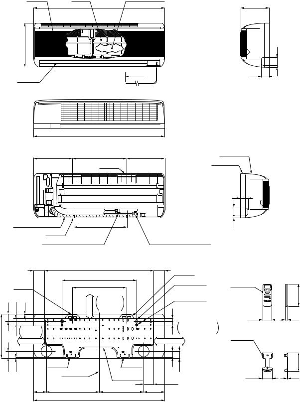
2. CONSTRUCTION VIEWS
2-1. Indoor Unit
RAS-10SKH-E
RAS-10SKHX
Air inlet |
Air filter |
Heat exchanger |
|
790 |
174 |
265 |
АААААА€@@@@@@,,,,,,€€€€€ |
|
|
|
|
АААААА€@@@@@@,,,,,,€€€€€ |
|
|
50 |
|
|
|
|
|
|
1800 |
10SKH-E : Without power cord |
47 |
10 |
Air outlet |
|
10SKHX : With power cord |
|
|
Knock out system
|
790 |
|
|
232 |
326 |
232 |
Front panel |
|
|||
|
Hanger |
|
Back body |
|
|
|
|
|
47 |
|
|
50 |
Drain hose (0.54m) |
321 |
10 |
Hanger |
|
Knock out system |
|
|
|
Connecting pipe (0.39m) |
Connecting pipe (0.49m) |
|
|
(Flare ø9.52) |
(Flare ø6.35) |
|
|
65.5 |
|
659 |
65.5 |
Hanger |
Wireless |
|
|
|
|
450 |
|
||
|
|
|
|
|
For stud bolt |
remote |
|
|
Hanger |
|
326 |
|
control |
||
|
|
|
(ø8~ø10) |
||||
|
|
|
|
66 or more |
|
|
|
|
|
|
|
|
|
|
|
|
|
|
|
Minimum |
|
For stud bolt |
|
46 |
20 |
2.5 |
|
distance |
20 |
(ø6) |
|
|
to ceiling |
|
|
||||
|
|
|
|
|
|
|
|
|
|
|
|
|
|
|
55 |
|
|
Minimum |
|
|
20 |
Minimum |
Remote |
265 |
17 |
distance |
|
|
distance to wall |
control |
|
to wall |
|
|
|
holder |
|||
|
|
120 or more |
|
|
120 or more |
|
|
40.5 |
3.5 |
|
|
|
37 |
40.5 |
|
|
Hanger |
Hanger |
|
|
|||
|
|
|
|
|
|
||
|
|
|
Center line |
Installation |
|
|
59.6 |
|
|
|
plate outline |
|
|
||
|
|
|
|
60.5 |
|||
|
|
|
|
|
|||
|
|
|
|
|
|
||
|
|
76 |
319 |
269 |
126 |
|
|
|
|
|
|
790 |
|
|
|
|
|
|
|
– 6 – |
|
|
|
136
16
112.8 5

2-2. Outdoor Unit |
|
|
|||
RAS-10SAH-E |
|
|
|
||
RAS-10SAHX |
|
|
|
||
|
A Detail Drawing |
A |
36 |
||
|
|
|
600 |
|
|
|
|
36 |
R10 |
|
|
|
|
50 |
|
|
|
|
|
|
230 |
216 |
30 |
230 |
216 |
25 |
|
|
50 |
ø11x14 Hole |
ø6 Hole |
|
|||
|
|
||||
|
Handle |
|
|
|
|
|
|
|
11 |
|
Fan guard |
|
|
|
|
|
|
|
|
|
|
ø420 |
|
525 |
530 |
268
5
600 |
85 |
111
ø25 Drain hole |
|
Gas side (flare ø9.52) |
|
|
|
|
|
|
|
Liquid side (flare ø6.35) |
|
8-ø6 Holes |
200 |
|
(For fixing the outdoor unit) |
12 |
|
4-ø11x14 Long holes |
||
11 |
||
111 (For anchor bolt ø8-ø10) |
||
|
||
TOSHIBA |
Electric |
|
|
parts cover |
Z
|
54 |
62 |
|
|
Access for |
|
89 |
charging |
770 |
59 |
250 |
89
230
268
59 |
770 |
|
|
Z View |
|
or more |
600 |
|
Inlet port |
|
|
45 |
|
600 or more |
Inlet port |
|
|
|
|
|
100 or more |
Visible outline |
(Minimum distance |
|
of the product |
of the wall) |
more |
Outlet |
4-ø11x14 Long holes |
|
(For anchor bolt ø8-ø10) |
|||
port |
|||
or |
|
Center |
|
200 |
|
||
|
port |
Mounting dimension of anchor bolt
– 7 –
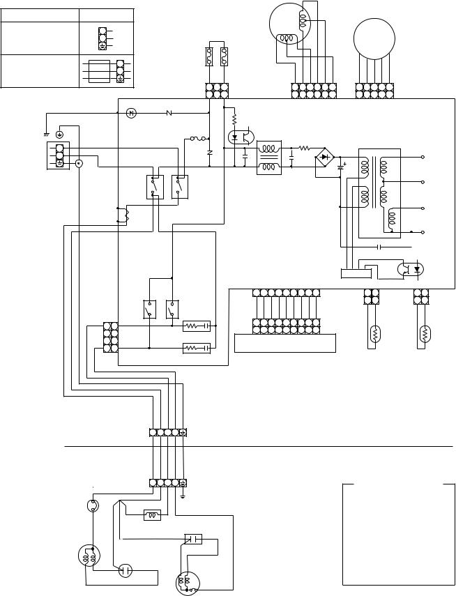
3. WIRING DIAGRAM
Model |
Section A |
|
RAS-10SKH-E/SAH-E |
L |
|
220/230/240V ~ |
N |
|
50Hz |
|
THERMAL FUSE |
|
|
|
RAS-10SKHX/SAHX |
L |
77˚C × 2 |
220/230/240V ~ |
N |
GRY |
|
||
50Hz |
|
|
1
1
BLK SG01 R109
GRN&YEL P04 DSA VARISTOR
F01 FUSE
|
LOUVER |
|
|
|
|
|
|
|
|
|
MOTOR |
|
|
|
|
|
DC |
|
FAN MOTOR |
|
|
|
|
|
|
|
|
||
|
|
|
|
|
|
|
|
|
|
|
|
|
|
|
|
MOTOR |
|
||
GRY |
|
BLU PNK YEL ORN RED BRW |
WHI BLU YEL BLK RED |
|
|||||
3 |
CN04 |
6 5 4 3 |
2 1 |
5 4 3 |
2 1 |
|
|||
3 |
CN07 6 |
5 4 |
3 |
2 1 |
5 4 |
3 |
2 1 |
CN10 |
|
|
R116 |
|
|
|
|
|
MAIN P.C. BOARD |
||
|
|
|
|
|
|
|
MCC-713 |
||
|
IC04 |
|
|
|
|
|
|
|
|
|
L |
BRW |
T3.15A |
R01 |
DB01 |
T01 |
|
|
|||||
Section A |
N |
|
250V |
C01 |
C02 |
DC35V |
BLU |
|
|||||
|
|
|
|
|
|
POWER |
|
3 |
|
|
3 R21 |
C15 |
L01 |
|
|
|
|
|
|
|
|
|
|
|
DC12V |
||
TERMINAL |
RY02 |
|
|
|
|
|
|
|
|
|
|
|
|
|
|
|
|
||||
|
|
|
RY01 |
|
|
|
|
|
|
|
|
|
|
|
|
|
|
||||
BLOCK |
|
|
|
|
|
|
|
|
|
|
|
|
|
|
|
|
|
|
|
||
|
|
|
|
|
|
|
|
|
|
|
|
|
|
|
|
|
|
|
|
|
|
|
|
4 |
|
|
4 |
|
|
|
|
|
|
|
|
|
|
|
|
|
|
DC7V |
|
|
T02 |
|
|
BLK |
|
|
|
|
|
|
|
|
|
|
|
|
|
|
|||
|
|
|
|
|
|
|
|
|
|
|
|
|
|
|
|
|
|
|
|||
|
C.T. |
|
|
|
|
|
|
|
|
|
|
|
|
|
|
|
|
|
|
|
|
|
WHI |
|
|
|
|
|
|
|
|
|
|
|
|
|
|
|
|
|
DC0V |
||
|
|
|
|
|
|
|
|
|
|
|
|
|
|
|
|
|
|
|
|
||
|
|
|
|
|
|
|
|
|
|
|
|
|
|
|
|
C06 |
|
IC02 |
|||
|
|
|
|
|
|
|
|
|
|
|
|
|
|
|
|
|
|
|
|||
|
|
|
|
|
|
|
|
|
|
|
|
|
|
|
IC |
|
|
|
|
|
|
|
|
|
|
|
|
|
|
|
|
|
|
|
|
|
IC01 |
|
|
|
|
|
|
|
|
RY03 |
RY04 |
1 |
2 |
3 4 |
5 |
6 |
7 |
8 |
9 |
CN13 |
1 |
2 |
CN03 |
1 |
2 |
CN01 |
|||
|
|
|
|
|
|
BLU BLU BLU BLU BLU BLU PNK BLK WHI |
1 |
2 |
|
|
1 |
2 |
|
||||||||
|
|
|
|
|
CR01 |
|
BLK BLK |
|
|
BLK BLK |
|
||||||||||
1 |
1 |
|
|
|
|
1 |
2 |
3 4 |
5 |
6 |
7 |
8 |
9 |
|
|
|
|
|
|
|
|
|
|
|
|
1 |
2 |
3 4 |
5 |
6 |
7 |
8 |
9 CN25 |
|
|
|
|
|
|
|
|||
|
2 |
|
|
|
|
|
|
|
|
|
|
|
|||||||||
|
|
|
|
CR02 |
INFRARED RAYS RECEIVE |
|
|
|
|
|
|
|
|||||||||
|
3 |
|
|
|
|
|
|
|
|
|
|
||||||||||
4 4 |
|
|
|
|
AND INDICATION PARTS |
THERMO |
|
HEAT |
|||||||||||||
CN27 |
|
|
|
|
|
|
|
|
|
|
|
|
|
|
|||||||
|
|
|
|
|
|
|
|
|
|
|
|
|
SENSOR |
EXCHANGER |
|||||||
|
|
|
|
|
|
|
|
|
|
|
|
|
|
|
|||||||
|
|
|
|
|
|
|
|
|
|
|
|
|
|
|
(TA) |
|
|
SENSOR |
|||
|
|
|
|
RED BLU GRN&YEL |
|
|
|
|
|
|
|
|
|
|
|
|
|
(TC) |
|
||
INDOOR |
BLK WHI |
|
|
|
|
|
|
|
|
DSA : Surge absorber |
|
|
|
||||||||
|
|
|
|
|
|
|
|
|
|
|
|
|
|
|
|
|
|
|
|
||
TERMINAL |
|
|
|
|
|
|
|
|
|
|
|
|
C.T : Current trans |
|
|
|
|
||||
BLOCK 1 |
2 3 4 |
|
|
|
|
|
|
|
|
|
|
|
|
||||||||
|
|
|
|
|
|
|
|
|
|
|
|
|
|
|
|
||||||
|
|
|
|
|
INDOOR |
|
|
|
|
|
|
|
|
|
|
|
|
|
|
|
|
|
|
|
|
|
OUTDOOR |
|
|
|
|
|
|
|
|
|
|
|
|
|
|
|
|
OVER LOAD |
|
1 |
2 3 4 |
|
|
|
|
|
|
|
|
|
COLOR IDENTIFICATION |
||||||||
RELAY |
|
|
|
|
|
|
|
|
|
|
|||||||||||
|
|
|
|
GRN & YEL |
|
|
|
|
|
|
|
|
|
|
BRW : BROWN |
|
|||||
BLK |
|
|
|
|
|
|
|
|
|
|
|
|
|
|
|
||||||
|
BLK |
CHASSIS |
|
|
|
|
|
|
|
|
|
|
RED : RED |
|
|
||||||
|
|
|
|
|
|
|
|
|
|
|
|
|
|
||||||||
|
BLK |
|
|
|
|
|
|
|
|
|
|
|
WHI : WHITE |
|
|
||||||
|
|
|
|
|
|
|
|
|
|
|
|
|
|
|
|
|
|||||
RED |
SOLENOID |
RUNNING |
|
|
|
|
|
|
|
|
|
|
YEL : YELLOW |
|
|||||||
|
|
|
|
|
|
|
|
|
|
BLU : BLUE |
|
|
|||||||||
|
CAPACITOR |
|
|
|
|
|
|
|
|
|
|
|
|
||||||||
|
|
COIL |
|
|
|
|
|
|
|
|
|
|
|
|
|
||||||
BLK |
|
|
|
|
|
|
|
|
|
|
|
|
|
BLK : BLACK |
|
|
|||||
|
RED |
|
|
|
|
|
|
|
|
|
|
|
|
|
|||||||
|
|
|
|
|
|
|
|
|
|
|
|
GRY : GRAY |
|
|
|||||||
|
|
|
|
|
|
|
|
|
|
|
|
|
|
|
|||||||
COMPRESSOR |
RUNNING |
|
RED |
|
|
|
|
|
|
|
|
|
|
PNK : PINK |
|
|
|||||
CAPACITOR |
|
|
|
|
|
|
|
|
|
|
|
|
|||||||||
|
|
|
|
|
|
|
|
|
|
ORN : ORANGE |
|
||||||||||
PNK |
|
|
|
|
WHI |
|
|
|
|
|
|
|
|
|
|
|
|||||
|
|
|
|
|
|
|
|
|
|
|
|
|
|
GRN&YEL : GREEN & |
|
||||||
|
|
|
|
|
|
|
|
|
|
|
|
|
|
|
|
||||||
WHI |
|
|
|
|
BLK |
|
|
|
|
|
|
|
|
|
|
|
|
YELLOW |
|
||
|
|
|
|
|
|
|
|
|
|
|
|
|
|
|
|
|
|
|
|
||
|
|
|
|
|
|
|
|
|
|
|
|
|
|
|
|
|
|
|
|
|
|
|
|
|
|
|
FAN MOTOR |
|
|
|
|
|
|
|
|
|
|
|
|
|
|
|
|
– 8 –
4. SPECIFICATIONS OF ELECTRICAL PARTS
4-1. Indoor Unit
RAS-10SKH-E
RAS-10SKHX
No. |
Parts name |
Type |
Specifications |
|
|
|
|
|
|
|
|
ICF-35-19-3 |
|
|
1 |
Fan motor (for indoor) |
or |
Output (Rated) 19W, 2pole, 1phase, 220/230/240V, 50Hz |
|
|
|
TICF-35-19-3 |
|
|
|
|
|
|
|
2 |
Thermo sensor |
(microprocessor) |
10kΩ at 25°C |
|
(TA-sensor) |
||||
|
|
|
||
|
|
|
|
|
3 |
DC-DC transformer (T01) |
SWT-34 |
DC390V, Secondary DC35V, 12V, 7V |
|
|
|
|
|
|
4 |
Microcomputer |
TMP87CK40F |
|
|
|
|
|
|
|
5 |
Power relay (RY01), Com- |
DI1U |
Coil : DC12V 75mA, Rated AC250V 20A |
|
mon relay (RY02) |
||||
|
|
|
||
|
|
|
|
|
6 |
Heat exchanger sensor |
(microprocessor) |
10kΩ at 25°C |
|
(TC-sensor) |
||||
|
|
|
||
|
|
|
|
|
7 |
Line filter (L01) |
RF-103YOR6 |
10mH, AC 0.6A |
|
|
|
|
|
|
8 |
Diode (DB01) |
RBV-406 |
4A, 600V |
|
|
|
|
|
|
9 |
Capacitor (C02) |
CEAUF2W101M20 |
100μF, 450V |
|
|
|
|
|
|
10 |
Fuse (F01) |
MT3 |
T3.15A, 250V |
|
|
|
|
|
|
11 |
Relay (for outdoor fan motor, |
AJQ1341 |
Coil DC12V, 33mA, Rated 1A 250V AC |
|
solenoid coil) (RY03, RY04) |
||||
|
|
|
||
|
|
|
|
|
12 |
Power supply IC (IC01) |
MA2830-FJ |
4A, 600V |
|
|
|
|
|
|
13 |
Varistor (R21, 109) |
15G561K |
560V |
|
|
|
|
|
|
14 |
Resistor (R01) |
ERF-5TK5R6 |
5.6 Ω, 5W |
|
|
|
|
|
|
15 |
Current trans (T02) |
CT422920S-01 |
|
|
|
|
|
|
4-2. Outdoor Unit
RAS-10SAH-E
RAS-10SAHX
No. |
Parts name |
Type |
Specifications |
|
||
|
|
|
|
|
|
|
|
|
|
Output (Rated) 750W, 2pole, 1phase, 220/230/240V, 50Hz |
|||
|
|
|
|
|
|
|
1 |
Compressor |
PH120T1-4C |
Ω |
) |
Red-Black |
White-Black |
|
|
|
Winding resistance ( |
|
|
|
|
|
|
(at 20°C) |
|
4.53 |
8.73 |
|
|
|
|
|
|
|
|
|
|
Output (Rated) 18W, 6pole, 1phase, 220/230/240V, 50Hz |
|||
|
|
|
|
|
|
|
2 |
Fan motor (for outdoor) |
UE6-21SJ5P |
Ω |
) |
Red-Black |
White-Black |
|
|
|
Winding resistance ( |
|
|
|
|
|
|
(at 20°C) |
|
370 |
370 |
|
|
|
|
|
|
|
3 |
Running capacitor |
SK-50CMP |
500V AC, 1.5μF |
|
|
|
(for fan motor) |
|
|
|
|||
|
|
|
|
|
|
|
|
|
|
|
|
|
|
4 |
Running capacitor |
SK-40CMP25U1 |
400V AC, 25μF |
|
|
|
(for compressor) |
|
|
|
|||
|
|
|
|
|
|
|
|
|
|
|
|
|
|
5 |
Solenoid coil |
LB60012 |
AC : 200/240V |
|
|
|
(for 4-way valve) |
|
|
|
|||
|
|
|
|
|
|
|
|
|
|
|
|
|
|
6 |
Overload relay |
J-MRA99269-9200 |
U/T 6.8A (90°C), OPEN 135±5°C, CLOSE 69±11°C |
|||
|
|
|
|
|
|
|
– 9 –
|
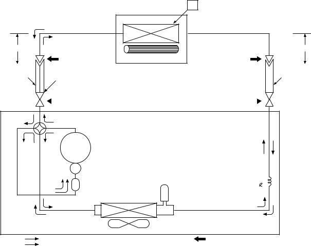
5. REFRIGERANT CYCLE DIAGRAM |
|
|
RAS-10SKH-E / RAS-10SAH-E |
|
|
|
RAS-10SKHX / RAS-10SAHX |
T1 |
|
|
|
|
|
|
|
|
Indoor unit |
|
|
Cooling |
Evaporator |
|
|
|
|
|
0.39m |
Heating |
|
0.49m |
|
|
(Connecting pipe) |
|
(Connecting pipe) |
|
||
ø9.52 |
|
Cross flow fan |
ø6.35 |
|
|
|
|
|
|
|
|
|
|
Optional piping kits |
|
|
|
|
|
|
|
|
|
|
|
|
|
|
|
|
|
O.D.:9.52mm |
|
P |
|
RB-P31BEF1 (3m) |
|
|
|
O.D.:6.35mm |
|||
|
|
|
|
|
|
RB-P51BEF1 (5m) |
|
|
|
|
|
|
|
|
|
|
|
RB-P71BEF1 (7m) |
|
|
|
|
|
|
|
|
Packed valve |
Packed valve |
|||||||
|
|
|
|
||||||||
|
|
|
|
(ø9.52) |
|
(ø6.35) |
|
|
|
|
|
|
|
|
|
|
|
|
|
|
|||
|
|
|
|
|
|
|
|
|
|||
Cooling |
Heating |
|
|
|
|
4-way valve |
|
|
|
Heating |
Cooling Compressor |
PH120T1-4C |
|
|
|
Accumulator |
|
Capillary tube |
|
|
|
ø1.7x1400 |
||
|
|
Dryer |
|
|
|
|
Condenser |
|
|
|
|
|
|
Refrigerant |
|
|
Propeller fan |
|
R-22 0.74kg |
|
Cooling |
Outdoor unit |
Mark( |
)means check points of Gas Leak |
|
Heating |
|
|
|
|
|
Fig. 5-1 |
|
|
Table 5-1
|
|
|
Standard pressure |
Surface temp. of heat |
|
Ambient temp. |
|||||
|
|
|
|
P |
|
exchanger interchanging |
|
||||
|
|
|
|
|
Fan speed |
conditions DB/WB |
|||||
|
|
|
|
|
|
|
|
|
|||
|
|
50Hz |
(kg/cm²G) |
pipe |
T1 |
(°C) |
|||||
|
|
(°C) |
|||||||||
|
|
(indoor) |
|||||||||
|
|
|
10SKH-E |
10SKH-E |
|||||||
|
|
|
|
|
|||||||
|
|
|
|
|
|
||||||
|
|
|
10SKHX |
10SKHX |
|
|
|
||||
|
|
|
|
Indoor |
Outdoor |
||||||
|
|
|
|
|
|
|
|
|
|
|
|
|
|
Standard |
15.0 |
40.0 |
|
High |
20/– |
7/6 |
|||
|
|
|
|
|
|
|
|
|
|
|
|
Heating |
High temperature*1 |
19 ~ 23 |
52.0 ~ 59.0 |
Low |
27/– |
21/15 |
|||||
|
|
Low temperature |
12.5 |
35.0 |
|
High |
20/– |
–10/–10 |
|||
|
|
|
|
|
|
|
|
|
|
|
|
|
|
Standard |
6.0 |
12.0 |
|
High |
27/19 |
35/24 |
|||
|
|
|
|
|
|
|
|
|
|
|
|
Cooling |
High temperature |
6.5 |
15.0 |
|
High |
32/23 |
43/26 |
||||
|
|
|
|
|
|
|
|
|
|
|
|
|
|
Low temperature |
4.0 |
2.0 |
|
Low |
21/15 |
21/15 |
|||
|
|
|
|
|
|
|
|
|
|
|
|
Note : |
|
|
|
|
|
|
|
|
|
|
|
• |
Measure the heat exchanger temperature at the center of U-bend. (By means of TC sensor.) |
|
|||||||||
*1 • |
During heating overload, the high temperature limit control operation is included. |
|
|
||||||||
– 10 –
– 11 –
Heat Exchanger Sensor
Thermo Sensor
Current Sensor
(Compressor Current)
Infrared Rays Signal Receiver
Infrared
Rays
Remote Control
Operation (START/STOP)
Operation Mode Selection
AUTO, COOL, DRY, HEAT, FAN ONLY
Thermo Setting
Fan Speed Selection
ON TIMER Setting
OFF TIMER Setting
Louver AUTO Swing
Louver Direction Setting
ECONO.
AC220/230/240V ~ 50Hz
Main Unit Control Panel |
C. P. U |
|||
|
|
|
|
|
Functions |
|
|
|
Operation |
|
|
|
Display |
|
|
|
|
|
|
• Louver Control |
|
|
|
|
|
|
|
|
|
|
|
|
Timer |
|
|
|
|
|
Display |
|
|
|
|
|
• 3-minute Delay at Restart for Compressor
ECONO.
Sign Display
Initializing Circuit |
|
|
• Motor Revolution Control |
|
|
|
|
|
|
|
|
PRE-DEF. |
|||||||
|
|
|
|
||||||||||||||||
|
|
|
|
|
|
|
|
|
|
|
|
|
|
|
|
|
|
|
Sign Display |
Clock Frequency |
|
|
• Processing |
|
|
|
|||||||||||||
|
|
|
|
|
|
|
|
|
|
|
|||||||||
|
|
|
|
|
|
|
|
|
|
|
|||||||||
Oscillator Circuit |
|
|
|
|
|
|
|
|
|
|
|
|
|||||||
|
|
|
(Temperature Processing) |
|
|
|
|
|
|
|
|
|
|||||||
|
|
|
|
|
|
|
|
|
|
|
|
|
|
Indoor |
|||||
|
|
|
|
|
|
|
|
|
|
|
|
|
|
|
|
|
|
|
|
|
|
|
|
|
|
|
|
|
|
|
|
|
|
|
|
|
|
||
|
|
|
|
|
|
• Timer |
|
|
|
|
|
|
|
|
|
|
|
Fan Motor |
|
|
|
|
|
|
|
|
|
|
|
|
|
|
|
|
|
||||
|
|
|
|
|
|
|
|
|
|
|
|||||||||
|
|
|
|
|
|
|
|
|
|
|
|
|
|
|
|
|
|
|
|
|
|
|
|
|
|
|
|
|
|
|
|
|
|
|
|
|
|
|
|
|
|
|
|
|
|
|
|
|
|
|
|
|
|
|
|
|
|
|
|
|
|
|
|
|
|
|
|
|
|
|
|
|
|
|
|
|
|
|
|
Power Supply |
|
|
Compressor |
|
Outdoor Fan |
|
4-Way Valve |
|
Louver |
|
|||||||||
Circuit |
|
ON/OFF Signal |
|
ON/OFF Signal |
|
ON/OFF Signal |
|
ON/OFF Signal |
|
||||||||||
|
|
|
|
|
|
|
|
|
|
|
|
|
|
|
|
|
|
|
|
|
|
|
|
|
|
|
|
|
|
|
|
|
|
|
|
|
|
|
|
Noise Filter Relay Driver, Louver Driver
Louver
Motor
Relay |
Relay |
Relay |
RY01 |
RY03 |
RY04 |
Relay
RY02
Compressor |
|
Outdoor Fan Motor |
|
4-Way Valve |
|
|
|
|
|
DIAGRAM BLOCK COMPUTER-MICRO .6
7. OPERATION DESCRIPTIONS
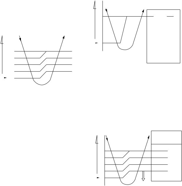
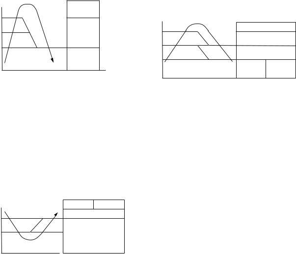
7-1. FAN ONLY Operation
(MODE of the remote control : FAN ONLY)
(1)During this mode, the relay RY01 is always turned off so that only the indoor fan is operated. RY02 is always turnd on.
1)When the FAN is set to AUTO, the indoor fan motor operates as shown in Fig 7-1-1.
2)When the FAN is set to LOW, MED, or HIGH, the indoor fan motor operates with a constant in volume as listed in Table 7-1-1.
Set temp.) |
28 |
|
||
– |
|
HIGH |
||
temp. |
27 |
|||
MED |
||||
|
|
|
||
(Room |
26 |
LOW(+) |
||
25 |
||||
|
|
|||
|
|
|
||
Set |
|
24 |
LOW |
|
|
|
|||
|
|
|||
temp. |
|
LOW |
||
|
|
|
|
|
Fig. 7-1-1 Auto setting of air volume
Table 7-1-1 Manual setting of FAN SPEED
Indication of |
HIGH Air volume |
FAN SPEED |
(m3/n) |
|
|
LOW |
400 |
|
|
MED |
500 |
|
|
HIGH |
600 |
|
|
(2)Once the setting is made, the operation mode is memorized in the microcomputer so that the same operation can be effected thereafter simply by
pushing the START/STOP button.
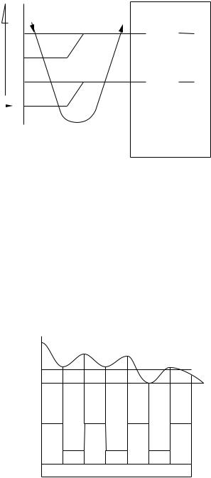
7-2. COOL Operation
(MODE of the remote control : COOL)
(1)Compressor 4-way valve, outdoor fan and operation display are controlled as shown in Fig. 7-2-1.
temp.) |
|
ON |
|
|
ON |
|
|
|
|
|
|
||||
Set– |
+1 |
|
|
|
|||
|
|
|
|
|
|||
|
|
|
|
|
|
|
|
temp. |
|
OFF |
ON |
OFF |
OFF |
ON |
|
|
|
|
|||||
(Room |
|
|
|
|
|||
|
|
|
|
|
|
||
Set |
|
0 |
|
|
|
|
|
temp. |
|
Compressor (RY01) |
relayCommon (RY02) |
valveway-4 (RY04) |
fanOutdoor (RY03) |
OPERATION display |
|
|
|
|
|
|
|
||
|
|
|
|
|
|
|
|
Fig. 7-2-1
(2)Relays RY01 and RY02 are turned on to energize the outdoor unit, and a cool operation is carried out.
1)When the FAN is set to AUTO, the indoor fan motor operates as shown in Fig 7-2-2.
2)When the FAN is set to LOW, MED, or HIGH, the indoor fan motor operates with a constant in volume as listed in Table 7-1-1.
|
|
|
|
FAN |
|
temp.) |
|
|
|
|
|
|
|
AUTO |
Manual |
||
|
|
|
|
||
Set– |
+4 |
|
HIGH |
|
|
|
MED |
|
|||
|
|
|
|
|
|
temp. |
+3 |
|
LOW(+) |
to the set |
|
|
|
|
|
|
According |
(Room |
+2 |
|
|
position |
|
|
|
LOW |
|||
+1 |
|
|
|||
|
|
|
|
||
|
|
|
|
|
|
Set |
|
0 |
|
LOW |
|
|
|
(continuous) |
|
||
|
|
||||
temp. |
|
|
|
|
|
|
RY01 |
|
|||
|
|
|
|
||
|
|
|
OFF |
|
|
Fig. 7-2-2
(3)Once the setting is made, the operation mode is memorized in the microcomputer so that the same operation can be effected thereafter simply by pushing the START/STOP button.
– 12 –
7-2-1. Louver Control
(1)By pushing the SET button of the remote control during the operation, the louver can be set to the desired position.
And the louver position is stored in the microcomputer, the louvers will be set to the position automatically at the next operation.
(2)When the AUTO button is pushed, the louver vertically swings within range of 25deg.
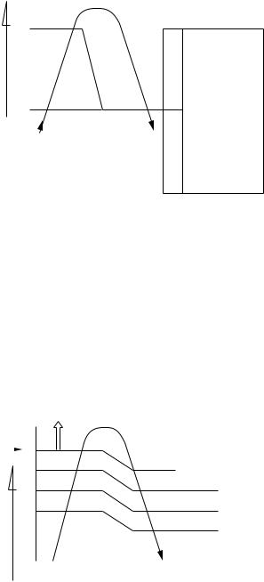
7-3. DRY Operation
(MODE of the remote control : DRY)
(1)Compressor 4-way valve, outdoor fan and operation display are controlled as shown in Fig. 7-3-1.
temp.) |
+3 |
ON:6min. |
OFF:4min. |
|
|
ON:6min. |
OFF:4min. |
|
||
temp.– Set |
ON:5min. |
OFF:5min. |
|
|
ON:5min. |
OFF:5min. |
|
|||
+2 |
ON |
OFF |
ON |
|||||||
(Room |
|
|
|
|
||||||
+1 |
OFF |
|
|
OFF |
|
|||||
|
|
|
|
|
|
|
|
|
||
Set |
|
0 |
|
|
|
|
|
|
|
|
temp. |
|
Compressor |
(RY01) |
relayCommon (RY02) |
valveway-4 (RY04) |
fanOutdoor |
(RY03) |
OPERATION display |
||
|
|
|
|
|
|
|
|
|||
|
|
|
|
|
|
|
|
|
|
|
Fig. 7-3-1
•The microprocessor turns the compressor on and off at regular intervals (4 to 6 minutes on and/or off). During the compressor off, the indoor fan will operate in the super low position.
•The indoor fan will operate in the AUTO position.
(2)The pattern of operation depending on the relation between room temperature and set temperature is shown below:
Room temp.
Set temp.+1
Set temp.
Compressor |
ON |
ON |
|
ON |
|
ON |
|
|
|
|
|
|
|
|
|
Outdoor fan |
|
OFF |
|
OFF |
OFF |
||
|
|
|
|||||
Indoor fan |
|
|
|
|
|
|
|
L. |
*S.L. |
L. |
S.L. |
L. |
S.L. |
L. |
|
|
*Super Low |
|
|
|
|
|
|
Fig. 7-3-2
– 13 –
7-4. HEAT Operation
(MODE of the remote control : HEAT)
(1)Relays, 4-way valve, outdoor fan and operation display are controlled as shown in Fig. 7-4-1.
temp.)Set– |
0 |
|
|
|
|
|
temp. |
|
OFF |
ON |
OFF |
|
|
|
|
|
||||
(Room |
|
|
ON |
|
ON |
|
–1 |
|
|
|
|
|
|
|
|
ON |
|
ON |
|
|
|
|
|
|
|
||
|
|
|
|
|
|
|
|
|
|
Compressor (RY01) Common relay (RY02) |
4-way valve (RY04) |
Outdoor fan (RY03) |
OPERATION display |
|
|
|
|
|
|
|
Fig. 7-4-1
(2)Relays RY01 and RY02 are turned on to energize the outdoor unit, and a heat operation is carried out. The indoor fan motor operates as shown in Fig. 7-4-2, when the FAN is set to AUTO.
The motor operates with a constant air volume as listed in Table 7-1-1, when the FAN is set to LOW, MED, or HIGH.
|
|
RY01 OFF |
FAN |
||
|
|
|
|||
|
|
|
|
|
|
Set |
|
0 |
AUTO |
Manual |
|
|
|
|
|||
|
|
|
|||
temp. |
|
|
|
||
temp.) |
-1 |
|
|
||
-2 |
LOW |
According |
|||
|
|
||||
|
|
LOW(+) |
|||
Set |
-3 |
to the set |
|||
MED(-) |
position |
||||
– |
-4 |
|
|||
temp.(Room |
|
|
|||
|
MED |
|
|||
|
|
|
|
||
|
|
|
|
|
|
Fig. 7-4-2
(3)Once the setting is made, the operation mode is memorized in the microcomputer so that the same operation can be effected thereafter simply by pushing the START/STOP button.
7-4-1. Louver Control
(1)By pushing the SET button of the remote control during the operation, the louver can be set to the desired position.
(2)When the AUTO button is pushed, the louver vertically swings within range of 25deg.
And the louver position is stored in the microcomputer, and at the next operation, the louvers will be set to the stored position automatically at the next operation.
7-4-2. Cool Airflow Control
(1)If the indoor heat-exchanger temperature detected by the indoor heat-exchanger sensor is 20°C or below, the indoor fan stops and if the temperature rises to 25°C or above, the fan is restarted.
Details are in 7-10.
– 14 –
7-5. AUTO Operation
(MODE of the remote control : AUTO)
(1)One of the 3 modes, Cooling, Fan only and Heating is selected according to room temperature at which operation is to start, as shown in Fig. 7-5-1. The Fan mode will continue until room temperature reaches a level at which another mode is selected.
7-5-1. Temporary Auto
When the TEMPORARY button is pushed, the set temperature is fixed at 24°C and controlled in accordance with the chart shown in Fig. 7-5-1.
(Room temp. – Set temp.)
|
Cooling mode |
(The same cooling mode as the room temperature control is set at set temp. –1˚C) |
||
|
|
The Louver moved downward. |
||
+4 |
|
|
|
|
Cooling mode |
(The same cooling mode as the room temperature control is set at set temp. –1˚C) |
|||
|
||||
+1 |
|
|
|
|
Fan only mode |
(Only the indoor fan operates at Low speed) |
|||
|
||||
–1 |
|
|
|
|
Heating mode |
(The same heating mode as the room temperature control is set at set temp. +1˚C) |
|||
|
||||
|
|
|
|
|
Fig. 7-5-1
– 15 –
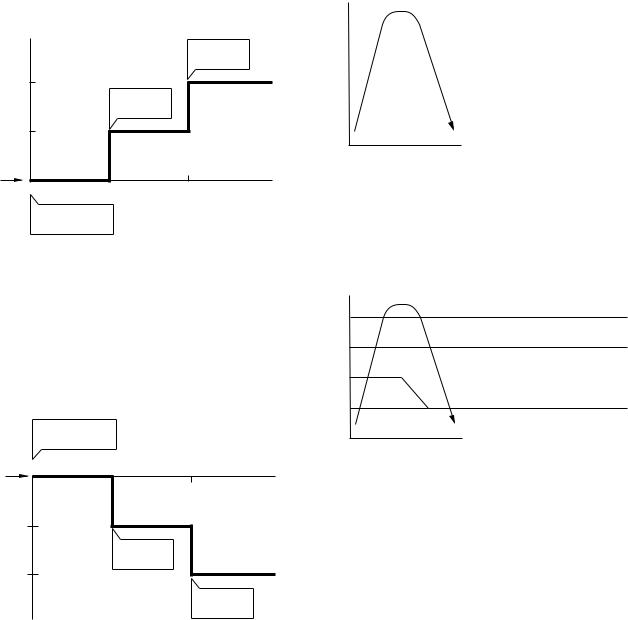
7-6. ECONO. Mode
When the ECONO. button is pushed, during COOL, HEAT and AUTO operation, the OPERATION display is turned off and the ECONO. display is lit and the indoor unit operates quietly and mildly with controlling airflow.
7-6-1. Cooling
(1)In the ECONO. mode, the set temp. by the remote control is changed automatically as shown in Fig. 7-6-1.
(2)Fan speed → LOW
(˚C) |
|
|
|
|
|
|
|
Set temp. |
|
|
|
|
is changed |
|
+2 |
|
|
|
|
|
|
Set temp. |
|
|
|
|
is changed |
|
|
+1 |
|
|
|
|
Set temp. |
0H |
1H |
2H |
TIME |
ECONO. button is pushed
Fig. 7-6-1
7-6-2. Heating
(1)In the ECONO. mode, the set temp. by the remote control is changed automatically as shown in Fig. 7-6-2.
(2)Fan speed → LOW
ECONO. button is pushed
0H |
1H |
2H |
TIME |
Set temp. |
|
|
|
-1 |
|
|
|
|
Set temp. |
|
|
|
is changed |
|
|
-2 |
|
|
|
|
|
Set temp. |
|
|
|
is changed |
|
(˚C) |
|
|
|
|
Fig. 7-6-2 |
|
|
7-7. Current Limit Control
The microprocessor detects the input current so as to prevent it exceeds a specified value by means of controlling the outdoor fan control as described in (1) and (2).
(1)Current limit control (Cooling)
Control is performed as shown below by detecting the compressor operation current with a current sensor (C.T).
|
|
|
|
Compressor |
|
Outdoor fan |
|
|
|
|
|
|
|
Input |
|
|
|
More than I4 continues for 3 seconds |
||
current |
|
OFF |
||||
10A |
I4 |
|
|
|
|
|
|
More than I3 continues for 5 minutes |
|||||
|
|
|
|
|||
9A |
I3 |
|
|
|
OFF |
|
|
|
|
|
|||
|
|
ON |
||||
|
|
|
|
|
||
|
|
|
|
|
|
|
Fig. 7-7-1
(2)Current limit control (Heating)
Control is performed as shown in Fig. 7-7-2.
|
|
Compressor |
|
Outdoor fan |
|
|
|
|
|
Input |
|
More than I4 continues for 3 seconds |
||
current |
|
OFF |
||
10A |
I4 |
More than I3 continues for 5 minutes |
||
|
|
|||
9A |
I3 |
|
OFF |
|
|
|
|
||
|
|
|
||
8A |
I2 |
ON |
|
OFF |
7.5A |
I1 |
|
|
|
|
ON |
|||
|
|
|
||
|
|
|
|
|
Fig. 7-7-2
– 16 –
7-8. High-Temperature Limit Control
(Heating Operation)
The microprocessor detects the indoor heat exchanger temperature so as to prevent exceeding the condensate pressure.
Control is performed as shown in Fig. 7-8-1.
Heat exchanger temperature
Compressor, (˚C) Outdoor fan
60 *1
53 |
OFF |
52
ON
*1 ····· Only outdoor fan is turned off.
Fig. 7-8-1
7-9. Low-Temperature Limit Control
(Cooling Operation)
The microprocessor detects the indoor heat exchanger temperature so as to prevent freezing up the indoor heat exchanger.
Control is performed as shown in Fig. 7-9-1.
Heat exchanger |
|
temperature |
Compressor Outdoor fan |
|
(˚C) |
ON |
|
7 |
||
Less than 5˚C continues |
||
|
||
5 |
for 5 minutes |
|
OFF |
Fig. 7-9-1
7-10. Cool Airflow Prevention Control
(Heating Operation)
(1)During the heating operation, the indoor fan speed is controlled automatically in accordance with the indoor heat exchanger temperature to prevent blowing the cool air.
Control is performed as shown in Fig. 7-10-1.
Heat exchanger temperature
(˚C)
30
25
20
Indoor fan speed
According to the set position
U.L. (Ultra Low)  Room temp. Room temp.
< |
> |
Set temp. |
Set temp. |
OFF |
S.L (Super Low) |
Fig. 7-10-1
(2) As soon as the defrost operation starts, the indoor fan stops.
– 17 –
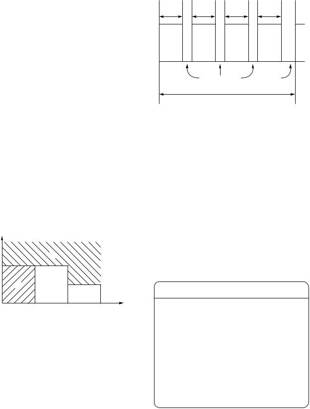
7-11. Defrost Operation
During the heating operation, the outdoor heat exchanger temperature goes down and sometimes it is frozen.
In this case, the air conditioner stops the heating operation and starts the defrost operation to melt ice.
7-11-1. Condition to Start the Defrost Operation
The defrost operation starts whichever below conditions are specified.
(1)When the cumulative compressor operation time is longer than 40 or 90 minutes and difference between the indoor heat exchanger temperature and the room temperature is less than the specified value. (This value is decided by the microprocessor.) (Control example is shown in Fig. 7-11-1. In case of B or C, the defrost operation starts.)
(2)When the current limit control or the high temperature limit control is performed for total of 90 minutes.
temp. |
(˚C) |
|
exchangerheatIndoor temp.–Room |
|
|
D |
|
19 |
|
|
|
|
|
|
|
|
|
|
10 |
A |
B |
Cumulative |
|
|
|
C |
compressor |
|
|
|
|
operation time |
|
|
40 |
90 |
(min.) |
Fig. 7-11-1 (Indoor fan speed : M)
7-11-2. Defrost Operation Time Control
<In case of B>
(1)The heating operation is performed for at least 40 minutes.
(2)The maximum defrost operation time is 6 minutes. The defrost operation time for the 4th cycle is 10 minutes. (When the outdoor temperature is very low, however, the defrost operation time is 10
minutes.)
minutes |
|
minutes |
|
minutes |
|
minutes |
|
40 |
|
40 |
|
40 |
|
40 |
|
Heating |
Defrost |
Heating |
Defrost |
Heating |
Defrost |
Heating |
Defrost |
|
|
Max 6 minutes |
10 minutes |
|
|||
|
|
|
1 cycle |
|
|
|
|
|
|
|
Fig. 7-11-2 |
|
|
|
|
<In case of C>
(1)The heating operation is performed for at least 90 minutes.
(2)The defrost operation time is 10 minutes.
7-11-3. Ending Condition at Defrost
Operation
(1)When the compressor current becomes 7.5A or more during defrost operation, the defrost operation stops and the heat operation restarts. (The current sensor detects the compressor current.)
(2)The defrost operation continues for at most 6 minutes or 10 minutes.
DEFROST LAMP :
•During defrost operation, the PRE-DEF. lamp is on and the indoor and outdoor fans are off.
•The compressor start protection timer is interlocked with the PRE-DEF. lamp. So the PREDEF. lamp is off (the fans stop) for about 3 minutes after the START/STOP button is turned on. When the compressor is turned on, the PRE-DEF. lamp comes on. After the heat exchanger is preheated to about 30°C or higher, the PRE-DEF. lamp goes off, and the indoor fan starts.
– 18 –
7-12. Auto Restart Function
This unit is equipped with an Automatic restarting facility which allows the unit to restart and resume the set operating conditions in the event of a power supply shutdown without the use of the hand control.
The operation will resume without warning three minutes after the power is restored.
The Auto Restart function is set not to work on shipment from the factory, and so it is necessary to set it to function as required.
• When the system is stand-by (not running)
7-12-1. How to Set the Auto Restart
To set the Auto Restart function, proceed as follows: Access the TEMPORARY button located in the lower right hand corner beneath the hinged front panel of the indoor unit (please refer to section on PARTS NAME). The power supply to the unit must be on - the function will not be set if the power is off.
To enable the Auto Restart function, press the TEMPORARY button continuously for three seconds. The unit will acknowledge the setting and beep three times. The system will now restart automatically.
The above Auto Restart settings can be carried out:
OPERATION |
|
MOTION |
|
|
|
|
|
Press the TEMPORARY button |
Stand-by |
|
|
continuously more than three |
↓ |
|
|
seconds. |
The system starts to operate. |
The green light will be lit. |
|
|
|
||
|
|
↓ |
about three seconds after |
0 |
The unit beeps three times. |
The orange light will be lit. |
|
|
3S |
↓ |
|
|
|
|
|
TEMPORARY |
The system is operating. |
The orange light is lighting. |
|
|
|
||
|
|
If the system is not required to run at this time, press the TEMPORARY |
|
|
|
||
|
|
button once more or use the remote control and the unit will stop. |
|
|
|
|
|
• When the system is operating |
|
|
|
|
|
|
|
OPERATION |
|
MOTION |
|
|
|
|
|
Press the TEMPORARY button |
Operating |
The green light is lit. |
|
continuously more than three |
↓ |
|
|
seconds. |
The system stops to operate. |
The green light is turned off. |
|
|
|
||
|
|
↓ |
about three seconds after |
0 |
The unit beeps three times. |
|
|
|
3S |
↓ |
|
|
|
|
|
|
|
The system stops. |
|
TEMPORARY |
|
|
|
|
|
If the system is not required to stop at this time, use the remote control |
|
|
|
||
|
|
and to restart. |
|
|
|
|
|
During subsequent operation, the orange light is lit.
•The Auto Restart function will not accept an instruction if timer operation with the remote control is selected.
(Please refer to the section on setting the timer or setting the louver.)
•During louver swing (AUTO) operation, after restart by the Auto Restart function the louver swing stops.
– 19 –
 Loading...