


29CZ5DE

SERVICE MANUAL
Color Television
FILE NO. 060-200565GR
Published in Singapore, October 2005 GREEN
Color Television
S5ES series
29CZ5DE
29CZ5T
29CZ6SI
SUPPLEMENT
© TOSHIBA SINGAPORE PTE LTD
The above models are classified as green products (*1), as indicated by the underlined serial numbers. This Service
Manual describes replacement parts for the green products. When repairing these green product (s), use the part (s)
described in this manual and lead-free solder (*2).
For (*1) and (*2), see the next page.

– 2 –
(*2)
LEAD-FREE SOLDER
This product is manufactured using lead-free solder as a part of a movement within the consumer products industry at large
to be environmentally responsible. Lead-free solder must be used in the servicing and repair of this product.
WARNING
This product is manufactured using lead free solder.
DO NOT USE LEAD BASED SOLDER TO REPAIR THIS PRODUCT!
The melting temperature of lead-free solder is higher than that of leaded solder by 86˚F to 104˚F (30˚C to 40˚C). Use of a
soldering iron designed for lead-based solders to repair product made with lead-free solder may result in damage to the
component and or PCB being soldered. Great care should be made to ensure high-quality soldering when servicing this
product -especially when soldering large components, through-hole pins, and on PCBs - as the level of heat required to
melt lead-free solder is high.
(*1)
GREEN PRODUCT PROCUREMENT
The EC is actively promoting the WEEE & RoHS Directives that define standards for recycling and reuse of Waste Electri-
cal and Electronic Equipment and for the Restriction of the use of certain Hazardous Substances. From July 1, 2006, the
RoHS Directive will prohibit any marketing of new products containing the restricted substances.
Increasing attention is given to issues related to the global environmental. Toshiba Corporation recognizes environmental
protection as a key management tasks, and is doing its utmost to enhance and improve the quality and scope of its
environmental activities. In line with this, Toshiba proactively promotes Green Procurement, and seeks to purchase and
use products, parts and materials that have low environmental impacts.
Green procurement of parts is not only confined to manufacture. The same green parts used in manufacture must also be
used as replacement parts.
TABLE OF CONTENTS
CHAPTER 1 GENERAL ADJUSTMENTS
SAFETY INSTRUCTIONS ............................................................................................................................................. 3
SET-UP ADJUSTMENT ................................................................................................................................................. 4
SERVICE MODE ........................................................................................................................................................... 8
DESIGN MODE ........................................................................................................................................................... 11
ELECTRICAL ADJUSTMENTS ................................................................................................................................... 12
CIRCUIT CHECK ......................................................................................................................................................... 13
CHAPTER 2 SPECIFIC INFORMATIONS
SETTING & ADJUSTING DATA ................................................................................................................................... 14
NAMES AND FUNCTIONS OF CONTROLS .............................................................................................................. 15
PROGRAMMING CHANNEL MEMORY...................................................................................................................... 16
PROCEDURES TO SET HOTEL MODE ..................................................................................................................... 18
CHASSIS AND CABINET REPLACEMENT PARTS LIST ........................................................................................... 19
PC BOARDS BOTTOM VIEW...................................................................................................................................... 26
TERMINAL VIEW OF TRANSISTORS ........................................................................................................................ 30
CIRCUIT BLOCK DIAGRAM ....................................................................................................................................... 32
SPECIFICATIONS .................................................................................................................................................... END
APPENDIX:
CIRCUIT DIAGRAM

GENERAL ADJUSTMENTS
SPECIFIC INFORMATIONS
– 3 –
2. The only source of X-RAY RADIATION in this TV receiver
is the picture tube. For continued X-RAY RADIATION
protection, the replacement tube must be exactly the same
type tube as specified in the parts list.
3. Some part in this receiver have special safety-related
characteristics for X-RAY RADIATION protection. For
continued safety, parts replacement should be undertaken
only after referring to the PRODUCT SAFETY NOTICE
below.
SAFETY PRECAUTION
WARNING : Service should not be attempted by anyone unfamiliar with the necessary precautions on this receiver. The following
are the necessary precautions to be observed before servicing this chassis.
1. An isolation transformer should be connected in the power line between the receiver and the AC line before any service is
performed on the receiver.
2. Always discharge the picture tube anode to the CRT conductive coating before handling the picture tube. The picture tube
is highly evacuated and if broken, glass fragments will be violently expelled. Use shatter proof goggles and keep picture
tube away from the unprotected body while handling.
3. When replacing a chassis in the cabinet, always be certain that all the protective devices are put back in place, such as;
nonmetallic control knobs, insulating covers, shields, isolation resistor-capacitor network etc.
CHAPTER 1 GENERAL ADJUSTMENTS
SAFETY INSTRUCTIONS
WARNING: BEFORE SERVICING THIS CHASSIS, READ THE “X-RAY RADIATION PRECAUTION”, “SAFETY PRECAU-
TION” AND “PRODUCT SAFETY NOTICE” INSTRUCTIONS BELOW.
X-RAY RADIATION PRECAUTION
1. Excessive high voltage can produce potentially hazardous
X-RAY RADIATION. To avoid such hazards, the high
voltage must not be above the specified limit. The nominal
value of the high voltage of this receiver is (A) kV at zero
beam current (minimum brightness) under a (C) V AC
power source. The high voltage must not, under any
circumstances, exceed (B) kV.
Refer to table-1 for high voltage (A), (B) & AC voltage (C).
(See SETTING & ADJUSTING DATA on page 14)
Each time a receiver requires servicing, the high voltage
should be checked following the HIGH VOLTAGE CHECK
procedure in this manual. It is recommended that the
reading of the high voltage be recorded as a part of the
service record. It is important to use an accurate and
reliable high voltage meter.
PRODUCT SAFETY NOTICE
Many electrical and mechanical parts in this chassis have special safety-related characteristics. These characteristics are
often passed unnoticed by a visual inspection and the protection afforded by them cannot necessarily be obtained by using
replacement components rated for higher voltage, wattage, etc. Replacement parts which have these special safety char-
acteristics are identified in this manual and its supplements; electrical components having such features are identified by the
international hazard symbols on the schematic diagram and the parts list.
Before replacing any of these components, read the parts list in this manual carefully. The use of substitute replacement
parts which do not have the same safety characteristics as specified in the parts list may create shock, fire, X-ray radiation
or other hazards.

GENERAL ADJUSTMENTS
SPECIFIC INFORMATIONS
– 4 –
SET-UP ADJUSTMENT
R The following adjustments should be made when a complete realignment is required or a new picture tube is installed.
Perform the adjustments in order as follows :
1. Color Purity
2. Convergence
3. White Balance
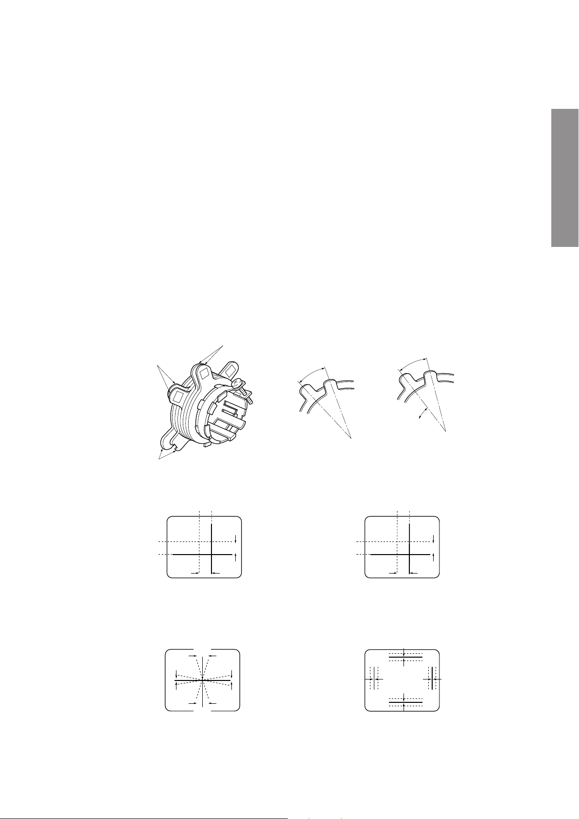
Note: The PURITY/CONVERGENCE MAGNET assembly and rubber wedges need mechanical positioning.
Refer to figure 1.
Mounting position of the purity magnet assembly should fit to same position as old one because slightly difference to
the position depend on a kind of tube.
*
There are no adjustment of purity and convergence in some picture tube (Unified with purity magnet)
5. Remove the Rubber Wedges.
6. Rotate and spread the tabs of the purity magnet (See fig-
ure 2.) around the neck of the picture tube until the green
belt is in the center of the screen. At the same time, enter
the raster vertically.
7. Slowly move the yoke forward or backward until a uniform
green screen is obtained. Tighten the clamp screw of the
yoke temporarily.
8. Check the purity of the red and blue raster.
GLASS CLOTH
TAPES
DEFLECTION
YOKE
TEMPORARY
MOUNTING
RUBBER WEDGE
ADHESIVE
DEFLECTION
YOKE
PURITY/
CONVERGENCE
MAGNET ASS'Y
29.1mm(28", 29")
25mm(25")
19mm(19", 20", 21")
14mm(13", 14")
Figure 1.
WARNING: BEFORE SERVICING THIS CHASSIS, READ THE “X-RAY RADIATION PRECAUTION”, “SAFETY PRECAU-
TION” AND “PRODUCT SAFETY NOTICE” ON PAGE 3 OF THIS MANUAL.
COLOR PURITY ADJUSTMENT
NOTE : Before attempting any purity adjustments, the
receiver should be operated for at least fifteen min-
utes.
1. Demagnetize the picture tube and cabinet using a degauss-
ing coil.
2. Set the brightness and contrast to maximum.
3. Use a green raster from a signal generator.
4. Loosen the clamp screw holding the yoke and slide the
yoke backward or forward to provide vertical green belt
(zone) in the picture screen.
GENERAL ADJUSTMENTS
SPECIFIC INFORMATIONS
– 5 –
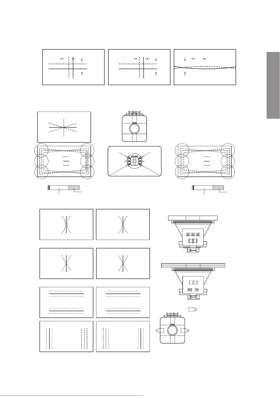
Figure 2.
BLU RED
BLU
RED
RED/BLU GRN
RED/BLU
GRN
B
G
R
R
G
B
BGR
RGB
BGR
RGB
R
G
B
B
G
R
4-POLE MAGNETS MOVEMENT
INCLINE THE YOKE UP (OR DOWN)
6-POLE MAGNETS MOVEMENT
Center Convergence by Convergence Magnets
Circumference Convergence by DEF Yoke
INCLINE THE YOKE RIGHT (OR LEFT)
Figure 3. Dot Movement Pattern
4-POLE
MAGNETS
PURITY
MAGNETS
6-POLE
MAGNETS
ADJUST THE ANGLE
(VERTICAL LINES)
FIXED
ROTATE TWO TABS
AT THE SAME TIME
(HORIZONTAL LINES)
CONVERGENCE MAGNET ASSEMBLY ADJUSTMENT OF MAGNETS
R CIRCUMFERENCE CONVERGENCE ADJUSTMENT
1. Loosen the clamping screw of deflection yoke slightly to
allow the yoke to tilt.
2. Temporarily put a wedge as shown in figure 1. (Do not
remove cover paper on adhesive part of the wedge.)
3. Tilt front of the deflection yoke up or down to obtain better
convergence in circumference. (See figure 3.) Push the
mounted wedge into the space between picture tube and
the yoke to fix the yoke temporarily.
4. Put other wedge into bottom space and remove the cover
paper to stick.
5. Tilt front of the yoke right or left to obtain better convergence
in circumference. (See figure 3.)
6. Keep the yoke position and put another wedge in either
upper space. Remove cover paper and stick the wedge on
picture tube to fix the yoke.
7. Detach the temporarily mounted wedge and put it in an-
other upper space. Stick it on picture tube to fix the yoke.
8. After fixing three wedges, recheck overall convergence.
Tighten the screw firmly to fix the yoke and check the yoke
is firm.
9. Stick three adhesive tapes on wedges as shown in figure
1.
CONVERGENCE ADJUSTMENTS
NOTE: Before attempting any convergence adjustments, the
receiver should be operated for at least fifteen
minutes.
R CENTER CONVERGENCE ADJUSTMENT
1. Use the cross-dot pattern from a signal generator.
2. Set the brightness and contrast for well defined pattern.
3. Adjust two tabs of the 4-Pole Magnets to change the angle
between them (See figure 2.) and superimpose red
and blue vertical lines in the center area of the picture
screen.
4. Turn the both tabs at the same time keeping the angle
constant to superimpose red and blue horizontal lines at
the center of the screen.
5. Adjust two tabs of 6-Pole Magnets to superimpose red/
blue line and green one. Adjusting the angle affects the
vertical lines and rotating both magnets affects the
horizontal lines.
6. Repeat adjustments 3, 4, 5 keeping in mind red, green
and blue movement, because 4-Pole Magnets and 6-Pole
Magnets have mutual interaction and make dot movement
complex.

WARNING: BEFORE SERVICING THIS CHASSIS, READ THE “X-RAY RADIATION PRECAUTION”, “SAFETY PRECAU-
TION” AND “PRODUCT SAFETY NOTICE” ON PAGE 3 OF SERVICE MANUAL.
SET-UP ADJUSTMENT (FOR FLAT TUBE)
■ The following adjustments should be made when a complete realignment is required or a new picture tube is installed.
Perform the adjustments in order as follows :
1. Color Purity
2. Convergence
3. White Balance
Note:The PURITY/CONVERGENCE MAGNET assembly and rubber wedges need mechanical positioning.
Refer to figure 1.
COLOR PURITY ADUSTMENT
(1)Let the screen face in the installing direction or toward the east (when it is to be moved), bring up the service mode
screen after demagnetizing (front, left, right, and top) with the degaussing coil, receive white signals by pressing the
[TV/VIDEO] button, and then the receiver should be operated for more than 40 minutes.
(2)Perform rough adjustment of the central convergence with the P/C magnet according to the adjustment item.
(3)Receive built-in green signals, loosen set screws on the deflection yoke, remove rubber wedges, and shift the deflection
yoke to toward front.
(4)Move alternately the two 2-pole magnets of the P/C magnets so that the green raster can come to the center of the
screen.
Figure 1.
(5)Receive built-in red and blue signals, check that there is no inclination of the single color raster toward one side, and if
each color tilts to a great extent, make adjustment with the 2-pole magnet so that the 3 colors will come to the center
evenly.
(6)Receive the green raster, shift the deflection yoke from a
foremost position (hitting against the picture tube) to a
backward position horizontally, stop the deflection yoke
at a position where it begins to become a green raster,
and perform accurate marking on the picture tube.
(7)Shift the deflection yoke further backward, and perform
accurate marking at a position where the green raster
begins to being luck.
(8)Fix the deflection yoke at a position 60% forward within
the range marked in items (6) and (7) above.
CONVERGENCE ADJUSTMENTS
* Adjust the convergence magnet to get vest convergence in the the order to (1) ~ (5).
■ CENTER CONVERGENCE:
(1)Receive the white crosshatch or dot pattern from the service signal generator.
(2)Use the 2 pieces of main 4-pole magnets of P/C magnets, change the open angle, and align the red and blue vertical
lines on the screen center.
(3)Freeze the open angle of the main 4-pole magnets, turn them simultaneously, and align the horizontal lines.
(4)Take the same steps for items (2) and (3) above and align red/blue with green on the screen center using two 6-pole
magnets.
A
P/C magnet installing position A
• 30"=26.5 mm
• 32"=30.5 mm or 32.5 mm
• 34"=37 mm
• 34"=39 mm
Green Belt
2-pole purity magnet
(27": Magnet is fixed with deflection yoke.)
Main 4-pole convergence magnet (30" : 32")
6-pole convergence magnet (34")
Sub-4-pole convergence magnet (32" : 34")
Sub-4-pole convergence magnet (to be installed on deflection yoke for 30", 32")
6-pole convergence magnet (30" : 32")
Main 4-pole convergence magnet (34")
Fix the deflection yoke at a position 60% forward from a
point between (6) and (7)
Picture tube
Shift deflection yoke
(6)
(8)
(7) Perform marking of each point
on the tape of picture tube
CRT-D board
P/C Mag
100 60 0%
GENERAL ADJUSTMENTS
– 6 –
(5)Adjust the sub-4-pole magnets only in case there is any deviation of Xv bow-shaped convergence. (To be usually set at
the initial position)
Align both sides with the sub-4-pole magnets and minimize the deviation of blue and red with the main 4-pole magnets.
blue
blue
red
red
Main 4-pole magnet
red/blue
red/blue
green
green
6-pole magnet
Xv bow-shaped deviation of convergence
blue
red
Sub-4-pole magnet
■ CIRCUMFERENCE CONVERGENCE:
*
Perform correction in the following manner.
A
D
E
F
A
B
C
B
C
S
N
D
E
F
A
B
C
D
E
F
N
S
VR3
YV YHC
GH
GH
VR2 VR1
blue
green
red
• Adjust coils and minimize deviation
(The 27” unit has coils underneath it)
blue
green
red
(Parts code:23 948 274) TC-S
Blue color or blue mark
*Insert the correction piece between the
picture tube and the deflection yoke.
(Insertion position of correction
piece)
Bonded surface
blue
green
red
(Parts code:23 948 464)
Transparent
Bonded surface
Adjust VR 1 and minimize the deviation of YH. *Only 27", 30" and 32".
Red
green
blue
Red
green
blue
Red
green
blue
Red
green
blue
Adjust VR 2 (YHC) and minimize the deviation of YH.
Red
green
blue
Red
green
blue
Red
green
blue
Red
green
blue
Adjust VR 3 (YV) and minimize the deviation of YV.
Red
blue
green
Red
blue
green
Red
blue
green
Red
blue
green
Red
blue
green
blue
red
green
Red
blue
green
blue
red
green
■ 30", 27", 32"
■ 34"
27" (Part No. 23 947 371)
32", 30" (Part No. 23 947 121)
34" (Part No. 23 993 080)
Perform correction by inserting the
correction piece into the clear-
ance of terminal board coils of
the deflection yoke.
Note:
Perform insertion by turning the
metal side to the terminal board
side of the deflection yoke.
GENERAL ADJUSTMENTS
– 7 –

GENERAL ADJUSTMENTS
– 8 –
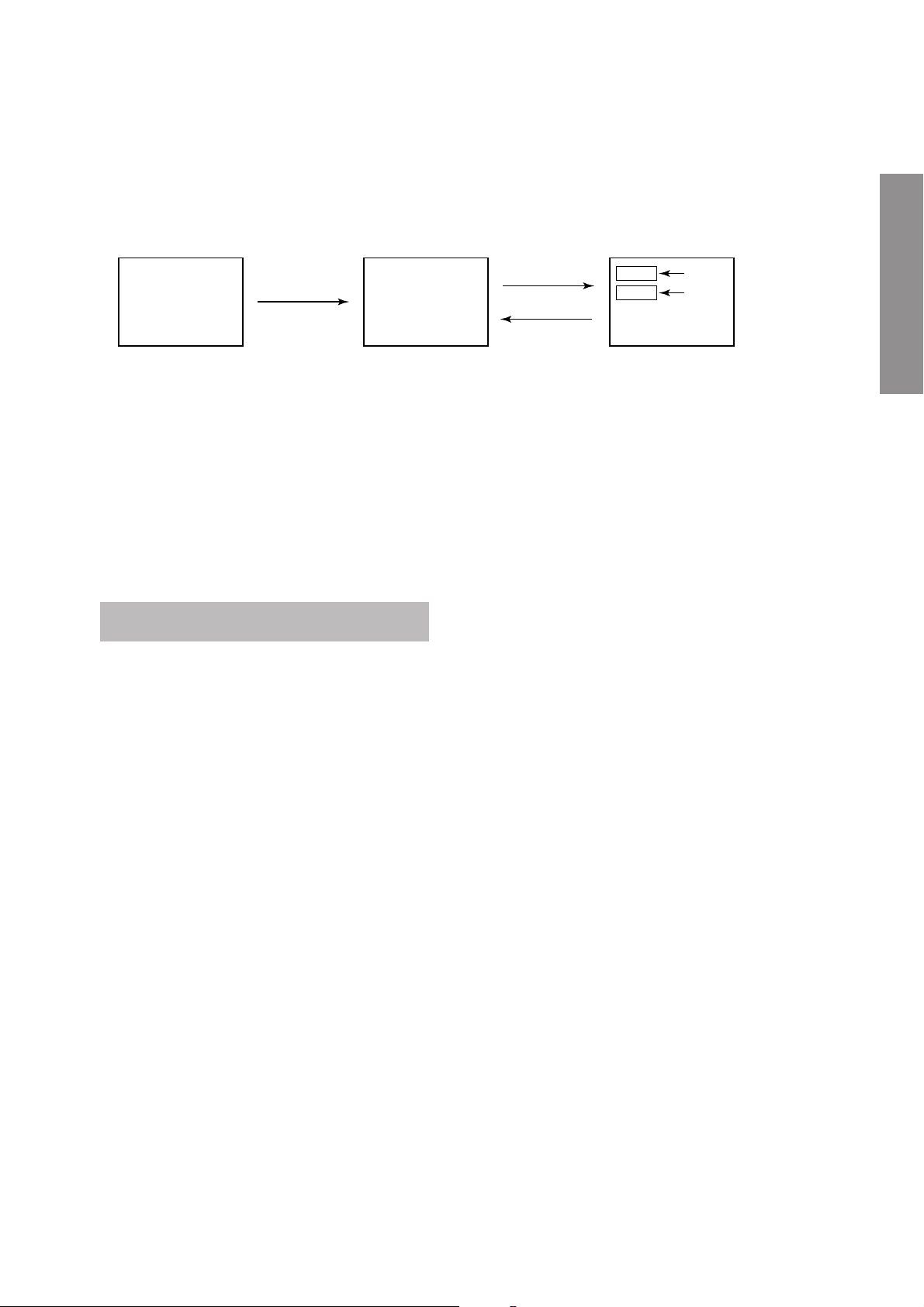
SERVICE MODE
1. ENTERING TO SERVICE MODE
1) Press o button once on
Remote Control.
2. DISPLAYING THE ADJUSTMENT MENU
1) Press MENU button on TV.
3. KEY FUNCTION IN THE SERVICE MODE
The following key entry during display of adjustment menu provides special functions.
A single horizontal line ON/OFF: - / - - button (on remote control)
Test signal ON/OFF : a button (on TV or remote control)
Selection of the adjustment items : Channel s/t (on TV or remote control)
Change of the data value : Volume ; +/– (on TV or remote control)
Adjustment menu mode ON/OFF : MENU button (on TV)
Initialization of the memory (QA10) : CALL + Channel button on TV (s)
Reset the count of operating protect
circuit to “00”: CALL + Channel button on TV (t)
“VG2” alignment : 0 button
“BCUT” selection : 1 button
“GCUT” selection : 2 button
“SCNT” selection : 4 button
“COLC” selection : 5 button
“TNTC” selection : 6 button
“SBY” selection : 7 button
Self diagnostic display ON/OFF : 9 button
CAUTION : Never try to perform initialization unless you have changed the memory IC.
2) Press o button again to
keep pressing.
3) While pressing the o button,
press MENU button on TV.
Color thickness correction
note: Displayed differently as shown below, depending
on the setting of the receiving color system.
COLP (PAL)
COLC (NTSC)
COLS (SECAM)
S
(Service mode display)
Item
Data
Adjustment mode
Press
Press
Service mode
Item
Data
S

GENERAL ADJUSTMENTS
– 9 –
4. SELECTING THE ADJUSTING ITEMS
1) Every pressing of CH s button in the service mode changes the adjustment items in the order of table-2.
(t button for reverse order)
Refer to table-2 for preset data of adjustment mode.
(See SETTING & ADJUSTING DATA on page 14)
5. ADJUSTING THE DATA
1) Pressing of ; +/– button will change the value of data in the range from 00H to FFH. The variable range depends on
the adjusting item.
6. EXIT FROM SERVICE MODE
1) Pressing POWER button to turn off the TV once.
R INITIALIZATION OF MEMORY DATA OF QA10
After replacing QA10, the following initialization is required.
1. Enter the service mode, then select any register item.
2. Press and hold the CALL button on the remote control, then press the CH s button on the TV. The initialization of QA10
has been completed.
3. Check the picture carefully. If necessary, adjust any adjustment item above.
Perform “ASM function” on the owner’s manual.
CAUTION: Never attempt to initialize the data unless QA10 has been replaced.

GENERAL ADJUSTMENTS
– 10 –
7. SELF DIAGNOSTIC FUNCTION
1) Press “9” button on the remote control during display of adjustment menu in the service mode.
The diagnosis will begin to check if interface among IC’s are executed properly.
2) During diagnosis, the following displays are shown.
Indicated color of mode now selected : Green and Red
Indicated color of other modes : White
Green : Normal
Red : The microprocessor operates to provide judgement
of no video signal.
OTHERS : (1) In case that power indicator is blinking with
interval of 0.5 seconds; it means protecting
circuit (Current limiter) is operating, and circuit
components may possibly be damaged.
Check related components.
(2) In case that power indicator is blinking with
interval of 1 second; Protecting circuit does
not operate, but a part of Bus line does not
operate normally. Check Bus line.
1 Part number of microprocessor (QA51)
2 Software type:
“ ECMVT A01” --------- Software for Asian models.
“ ERFAP R01” --------- Software for Russian models.
“ ERFAP P01” --------- Software for Middle East models.
3 Software version
4 Memory IC data version
5 Protection circuit operation count
6 BLOCK
UV : TV reception mode
V1 : VIDEO 1 input mode (a1)
V2 : VIDEO 2 input mode (a2)
V3 : VIDEO 3 input mode (a3)
MICON : 23
* * * * * *
S/W : E
* * * * *
01
V 1.00
EEP : V00
POWER : 000
BLOCK : UV V1 V2 V3
<SELF CHECK>
1
2
3
4
5
6
GENERAL ADJUSTMENTS
– 11 –
DESIGN MODE
2) While pressing CALL button
again and press MENU button
on the TV.
3) Press MENU button on TV.
ITEM
DATA
S D
Press
(Design mode) (Adjustment mode)
Press
1. ENTERING TO DESIGN MODE
1) When in Service mode (see
page 8), press CALL button
on the remote control once.
When QA10 is initialized, items “OPT” ,“OPT1” and “OPT2” of DESIGN MODE are set to the data of the representative model
of this chassis family.
Therefore, because ON-SCREEN specification remains in the state of the representative of model. This model is required to
reset the data of items “OPT” ,“OPT1” and “OPT2” according to current on-serviced model .
2. SELECTING THE ADJUSTING ITEMS
Every pressing of CH t button in the design mode changes the adjustment items in the order of table-3.
(s button for reverse order)
Refer to table-3 for data of design mode.
(See SETTING & ADJUSTING DATA on page 14)
3. ADJUSTING THE DATA
Pressing of ; -/+ buttons will change the value of data.
GENERAL ADJUSTMENTS
– 12 –
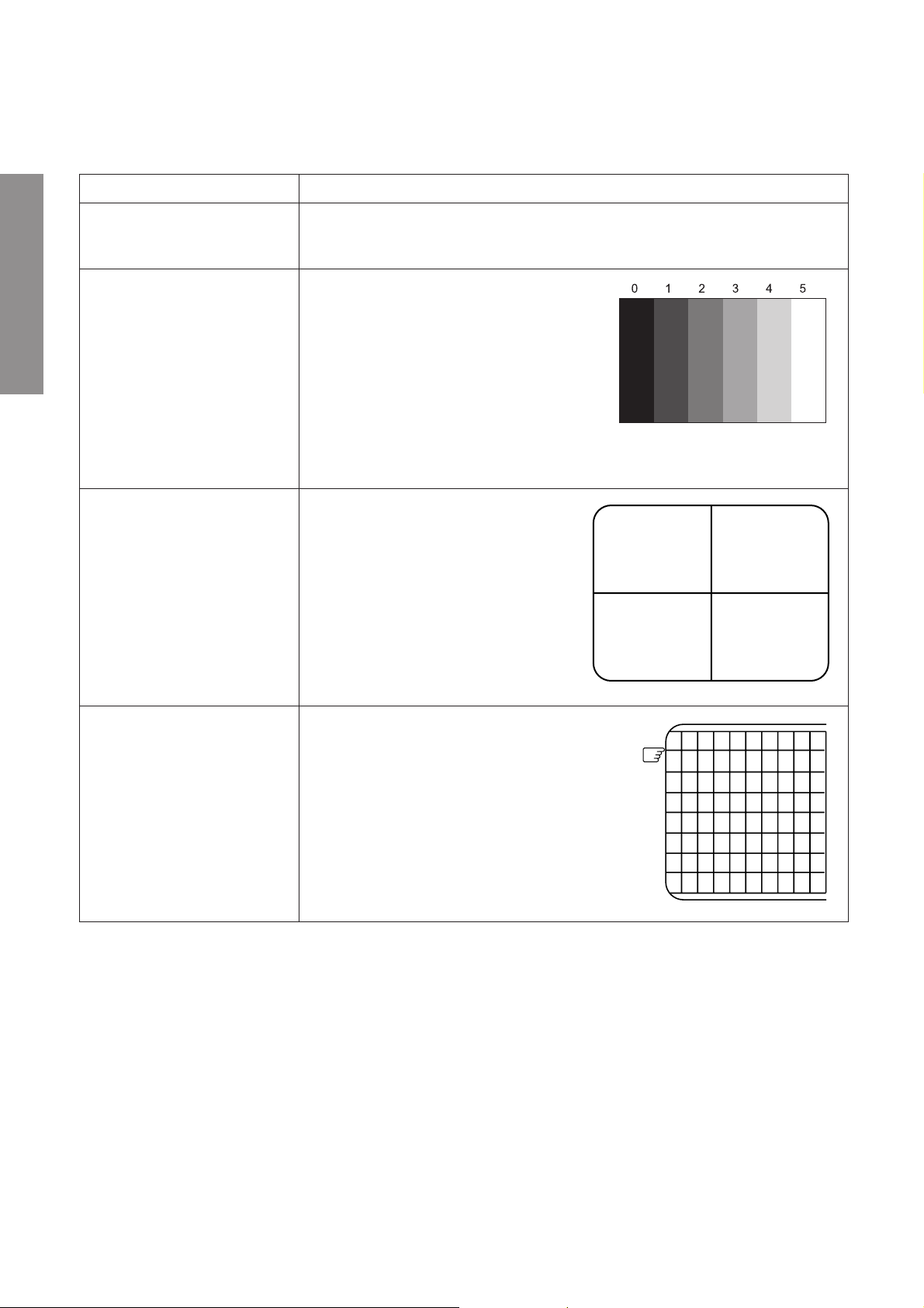
ELECTRICAL ADJUSTMENTS
FOCUS VR ADJ
SUB-BRIGHTNESS
(BRTC)
HORIZONTAL POSITION
ADJUSTMENT (HPOS)
VERTICAL POSITION
ADJUSTMENT (VPOS)
VERTICAL AMPLITUDE
ADJUSTMENT (HIT)
1. Enter the service mode, then input AV1 black cross-bar pattern with signal generator.
2. Adjust the FOCUS control (on T461) for well defined scanning lines on the picture
screen.
1. Input AV1 “5 steps pattern” with video signal
generator.
2. Set CONTRAST to minimum and
BRIGHTNESS to center by adjusting user
controls.
3. Enter Service mode and press CH s/t to
select BRTC.
4. Press ; –/+ buttons to adjust BRTC until
step 0 and step 1 has the same blackness.
5. Exit service mode and press h button to
set picture mode to DYNAMIC.
1. Enter the service mode, input AV1 black
or white cross-bar signal with signal
generator.
2. Select either HPOS (Horizontal picture
phase) or VPOS (Vertical picture
phase) with CH s/t buttons, and
adjust horizontal or vertical picture
position in the center of screen with
; –/+ buttons.
1. Enter the service mode, input AV1 black
or white cross-hatch signal with signal
generator.
2. Select HIT (Vertical amplitude) with
CH s/t buttons, and adjust vertical
amplitude with ; –/+ buttons so that
vertical amplitude lacks a little.
3. Adjust vertical amplitude with ; –/+
buttons so that the first bar on cross-
hatch signal touches edge of screen.
The first
ITEM
ADJUSTMENT PROCEDURE

GENERAL ADJUSTMENTS
– 13 –
WHITE BALANCE
ADJUSTMENT
SCREEN VOLTAGE ADJUST-
MENT (SCREEN VR) of FBT
• DRIVE ADJUSTMENT
(GDRV)
(BDRV)
(RDRV)
• CUTOFF ADJUSTMENT
(GCUT)
(BCUT)
ITEM
ADJUSTMENT PROCEDURE
1. Select AV1 (with no input).
2. Enter Service mode and press “0” button.
3. Adjust Screen VR until OSD “HBC” toggle
between 1 & 0.
4. Press “0” button again to exit.
5. Input AV1 “5 steps pattern” with video signal
generator.
6. Press h button to set picture mode to
DYNAMIC.
X To correct white balance in high light area
(steps 3 and 4) select GDRV, BDRV and
RDRV with ; – /+buttons.
X To correct white balance in low light area
(steps 1 and 2), select GCUT and BCUT.
CIRCUIT CHECK
HIGH VOLTAGE CHECK
CAUTION: There is no HIGH VOLTAGE ADJUSTMENT on this chassis. Checking should be done following the steps below.
1. Connect an accurate high voltage meter to the second anode of the picture tube.
2. Turn on the receiver. Set the BRIGHTNESS and CONTRAST controls to minimum (zero beam current).
3. High voltage must be measured below (B) kV.
Refer to table-1 for high voltage (B).
(See SETTING & ADJUSTING DATA on page 14)
4. Vary the BRIGHTNESS control to both extremes to be sure the high voltage does not exceed the limit under any conditions.

SPECIFIC INFORMATIONS
– 14 –
CHAPTER 2 SPECIFIC INFORMATIONS
SETTING & ADJUSTING DATA
SAFETY INSTRUCTIONS
SERVICE MODE
ADJUSTING ITEMS AND DATAS IN THE SERVICE MODE:
Table-1
Table-2
29"
HIGH VOLTAGE AT MAX BEAM CURRENT: (A) 30.0 kV
MAX HIGH VOLTAGE: (B) 32.0 kV
AC VOLTAGE (C) 110-240 V
BCUT B CUTOFF (B/W) 20H
←
GCUT G CUTOFF (B/W) 20H
←
RDRV R DRIVE 20H
←
GDRV G DRIVE 20H
←
BDRV B DRIVE 20H
←
BRTC SUB BRIGHT CENTER 24H
←
COLC SUB COLOR CENTER NTSC 1EH
←
TNTC SUB TINT CENTER 1EH
←
COLP SUB COLOR CENTER PAL 1DH
←
COLS SUB COLOR CENTER SECAM 1DH
←
SCNT SUB CONTRAST TV 00H
←
SBY SECAM B-Y BLACK OFFSET 01H
←
VPOS 50Hz V-POSITION 1CH
←
HIT HEIGHT 25H
←
VLIN V-LINEARITY 24H
←
HPOS H-POSITION 2BH
←
WID EW WIDTH 31H
←
PARA EW PARABOLA 17H
←
TRAP EW TRAPEZIUM 26H
←
TCNR EW UPPER PARABOLA 15H
←
BCNR EW LOWER PARABOLA 15H
←
HPLL
HORIZONTAL PARALLELOGRAM
22H
←
HBOW HORIZONTAL BOW 20H
←
XCAL CRYSTAL CALIBRATION 30H
←
RAGC AGC TAKE-OVER 12H
←
CTR1 CONTROL 1 07H
←
Item
Adjustment Reference Data
Adjust Data
SPECIFIC INFORMATIONS
– 15 –
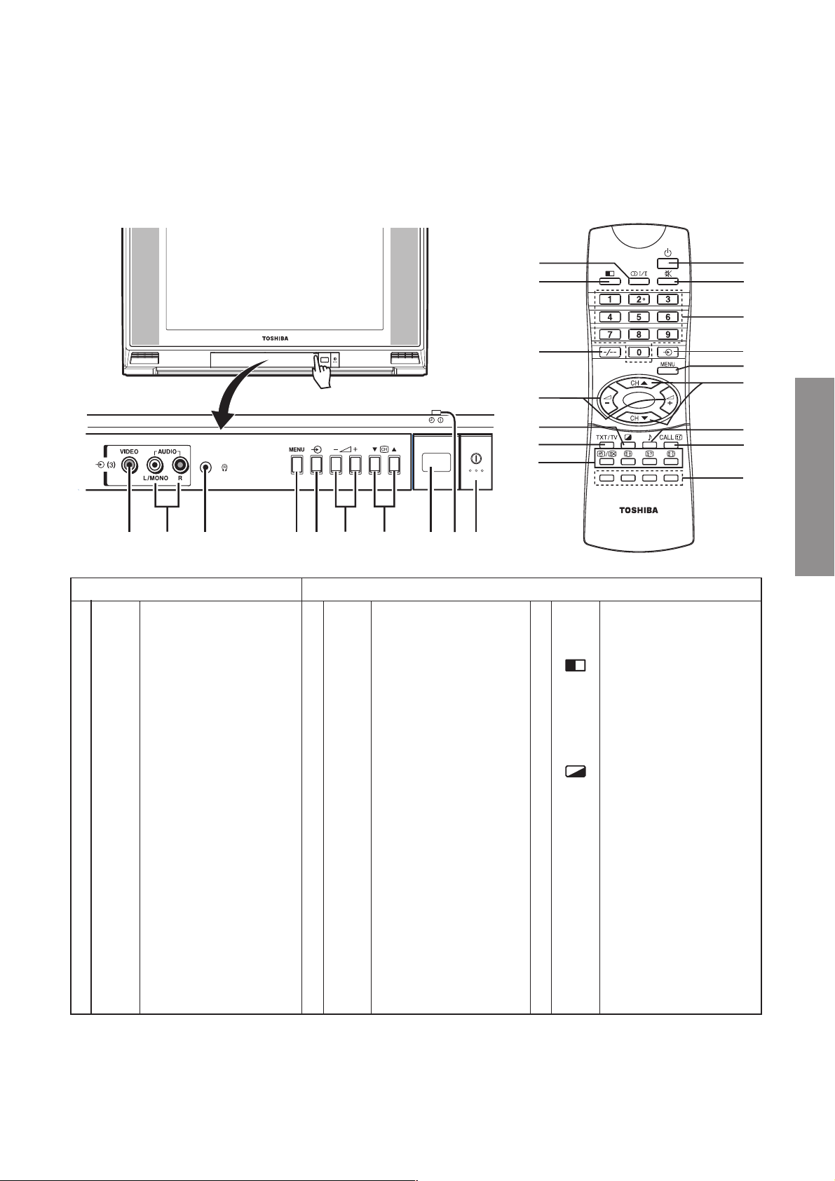
NAMES AND FUNCTIONS OF CONTROLS
Model 29CZ5DE is used in this manual for illustration purpose.
TV Front and Remote control
TV Remote Control
1
f
Power on/standby
2
o
Sound Mute, press
again or
;
-/+
to
restore the sound.
3
0~9
Number buttons
4
a
Input source selection,
Timer-ON position
setting
Switch the active
teletext page of the
double window mode
5
MENU
Turn on menu display
6
CH s/t
Channel up/down,
Menu item selection
7
8
Sound menu
8
CALL/i
On-screen on/off,
Turn off the menu,
Teletext initial/index
9 Teletext colored buttons
Red/Green/Yellow/Blue
!
mI/II
Stereo/bilingual
selection
"
Double-window on/off
#
-/--
Digit selection
$
;
-/+
Volume down/up,
Menu selection or
item adjust
%
Picture menu
&
TXT/TV
Teletext/TV selection
( Teletext functions
y/X
– Time display, To select
a page while viewing a
normal picture
^
– To enlarge teletext
display size
?
– To reveal concealed
text
v
– To hold a wanted page
1
2
3
4
5
6
7
8
9
!
"
#
$
%
&
(
a
e
f
h
c
b
g
i
j
d
Open the lid
a
q Main power on/off
b Remote sensor
c
q Power indicator (red)
r Timer-ON indicator
(green)
d
MENU Turn on menu display
e
a Input source selection
f
- ;
+
Volume down/up,
Menu selection or item
adjust
g
tc
s Channel down/up,
Menu item selection
h
L
Stereo headphones jack
(Ø3.5mm) for private
listening. The sound
from the speakers will
be cut off automatically.
i
AUDIO
Audio input terminals
j
VIDEO
Video input terminal
 Loading...