


 Loading...
FILE NO. 010-200317
SERVICE MANUAL
Color Television
F2DS Chassis
29SH9UH
34SH9UH
Jan., 2004

SPECIFIC INFORMATIONS GENERAL ADJUSTMENTS
TABLE OF CONTENTS |
|
CHAPTER 1 GENERAL ADJUSTMENTS |
|
SAFETY INSTRUCTIONS ........................................................................................................................................ |
3 |
SET-UP ADJUSTMENT ............................................................................................................................................ |
4 |
SERVICE MODE ...................................................................................................................................................... |
6 |
DESIGN MODE ........................................................................................................................................................ |
9 |
ELECTRICAL ADJUSTMENTS .............................................................................................................................. |
10 |
CIRCUIT CHECK .................................................................................................................................................... |
12 |
CHAPTER 2 SPECIFIC INFORMATIONS |
|
SETTING & ADJUSTING DATA .............................................................................................................................. |
13 |
LOCATION OF CONTROLS ................................................................................................................................... |
14 |
PROGRAMMING CHANNEL MEMORY ................................................................................................................. |
16 |
CHASSIS AND CABINET REPLACEMENT PARTS LIST ...................................................................................... |
18 |
PC BOARDS BOTTOM VIEW................................................................................................................................. |
33 |
TERMINAL VIEW OF TRANSISTORS ................................................................................................................... |
45 |
CIRCUIT BLOCK DIAGRAM .................................................................................................................................. |
47 |
SPECIFICATIONS .............................................................................................................................................. |
END |
APPENDIX: |
|
CIRCUIT DIAGRAM |
|
– 2 –

CHAPTER 1 GENERAL ADJUSTMENTS
SAFETY INSTRUCTIONS
WARNING: BEFORE SERVICING THIS CHASSIS, READ THE “X-RAY RADIATION PRECAUTION”, “SAFETY PRECAUTION” AND “PRODUCT SAFETY NOTICE” INSTRUCTIONS BELOW.
X-RAY RADIATION PRECAUTION
1.Excessive high voltage can produce potentially hazardous X-RAY RADIATION. To avoid such hazards, the high voltage must not be above the specified limit. The nominal value of the high voltage of this receiver is (A) kV at zero beam current (minimum brightness) under a (C) V AC power source. The high voltage must not, under any circumstances, exceed (B) kV.
Refer to table-1 for high voltage (A), (B) & AC voltage (C). (See SETTING & ADJUSTING DATA on page 13)
Each time a receiver requires servicing, the high voltage should be checked following the HIGH VOLTAGE CHECK procedure in this manual. It is recommended that the reading of the high voltage be recorded as a part of the service record. It is important to use an accurate and reliable high voltage meter.
2.The only source of X-RAY RADIATION in this TV receiver is the picture tube. For continued X-RAY RADIATION protection, the replacement tube must be exactly the same type tube as specified in the parts list.
3.Some part in this receiver have special safety-related characteristics for X-RAY RADIATION protection. For continued safety, parts replacement should be undertaken only after referring to the PRODUCT SAFETY NOTICE below.
SAFETY PRECAUTION
WARNING : Service should not be attempted by anyone unfamiliar with the necessary precautions on this receiver. The following are the necessary precautions to be observed before servicing this chassis.
1.An isolation transformer should be connected in the power line between the receiver and the AC line before any service is performed on the receiver.
2.Always discharge the picture tube anode to the CRT conductive coating before handling the picture tube. The picture tube is highly evacuated and if broken, glass fragments will be violently expelled. Use shatter proof goggles and keep picture tube away from the unprotected body while handling.
3.When replacing a chassis in the cabinet, always be certain that all the protective devices are put back in place, such as; nonmetallic control knobs, insulating covers, shields, isolation resistor-capacitor network etc.
PRODUCT SAFETY NOTICE
Many electrical and mechanical parts in this chassis have special safety-related characteristics. These characteristics are often passed unnoticed by a visual inspection and the protection afforded by them cannot necessarily be obtained by using replacement components rated for higher voltage, wattage, etc. Replacement parts which have these special safety characteristics are identified in this manual and its supplements; electrical components having such features are identified by the international hazard symbols on the schematic diagram and the parts list.
Before replacing any of these components, read the parts list in this manual carefully. The use of substitute replacement parts which do not have the same safety characteristics as specified in the parts list may create shock, fire, X-ray radiation or other hazards.
SPECIFIC INFORMATIONS GENERAL ADJUSTMENTS
– 3 –
SPECIFIC INFORMATIONS GENERAL ADJUSTMENTS
WARNING: BEFORE SERVICING THIS CHASSIS, READ THE “X-RAY RADIATION PRECAUTION”, “SAFETY PRECAUTION” AND “PRODUCT SAFETY NOTICE” ON PAGE 3 OF SERVICE MANUAL.
SET-UP ADJUSTMENT (FOR FLAT TUBE)
■The following adjustments should be made when a complete realignment is required or a new picture tube is installed. Perform the adjustments in order as follows :
1.Color Purity
2.Convergence
3.White Balance
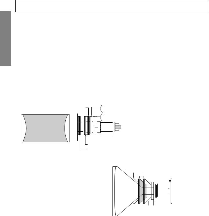
Note: The PURITY/CONVERGENCE MAGNET assembly and rubber wedges need mechanical positioning. Refer to figure 1.
COLOR PURITY ADUSTMENT
(1)Let the screen face in the installing direction or toward the east (when it is to be moved), bring up the service mode screen after demagnetizing (front, left, right, and top) with the degaussing coil, receive white signals by pressing the [TV/ VIDEO] button, and then the receiver should be operated for more than 40 minutes.
(2)Perform rough adjustment of the central convergence with the P/C magnet according to the adjustment item.
(3)Receive built-in green signals, loosen set screws on the deflection yoke, remove rubber wedges, and shift the deflection yoke to toward front.
(4)Move alternately the two 2-pole magnets of the P/C magnets so that the green raster can come to the center of the screen.
2-pole purity magnet
(27": Magnet is fixed with deflection yoke.)
Green Belt
Figure 1.
Main 4-pole convergence magnet (30" : 32") 6-pole convergence magnet (34")
6-pole convergence magnet (30" : 32")
Main 4-pole convergence magnet (34")
P/C magnet installing position A
• 30"=26.5 mm
 A
A 
• 32"=30.5 mm or 32.5 mm
• 34"=37 mm
• 34"=39 mm
Sub-4-pole convergence magnet (32" : 34")
Sub-4-pole convergence magnet (to be installed on deflection yoke for 30", 32”)
(5)Receive built-in red and blue signals, check that there is no inclination of the single color raster toward one side, and if each color tilts to a great extent, make adjustment with the 2-pole magnet so that the 3 colors will come to the center
evenly.
(6)Receive the green raster, shift the deflection yoke from a foremost position (hitting against the picture tube) to a backward position horizontally, stop the deflection yoke at a position where it begins to become a green raster, and perform accurate marking on the picture tube.
(7)Shift the deflection yoke further backward, and perform accurate marking at a position where the green raster begins to being luck.
(8)Fix the deflection yoke at a position 60% forward within the range marked in items (6) and (7) above.
CONVERGENCE ADJUSTMENTS
Shift deflection yoke
(6)(7) Perform marking of each point
(8)on the tape of picture tube
Picture tube |
|
|
|
|
|
|
|
|
|
|
|
CRT-D board |
|
|
|
|
|
|
|
|
|
|
|
||
|
|
|
|
|
|
|
|
|
|
|
||
|
|
|
|
|
|
|
|
|
|
|
|
|
|
|
|
|
|
|
|
|
|
|
|
|
|
|
|
|
|
|
|
|
|
|
|
|
|
|
|
|
|
|
|
|
|
|
|
|
|
|
|
 P/C Mag 100 60 0%
Fix the deflection yoke at a position 60% forward from a point between (6) and (7)
*Adjust the convergence magnet to get vest convergence in the the order to (1) ~ (5).
■CENTER CONVERGENCE:
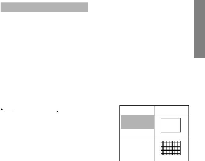
(1)Receive the white crosshatch or dot pattern from the service signal generator.
(2)Use the 2 pieces of main 4-pole magnets of P/C magnets, change the open angle, and align the red and blue vertical lines on the screen center.
(3)Freeze the open angle of the main 4-pole magnets, turn them simultaneously, and align the horizontal lines.
(4)Take the same steps for items (2) and (3) above and align red/blue with green on the screen center using two 6-pole magnets.
–4 –

(5)Adjust the sub-4-pole magnets only in case there is any deviation of Xv bow-shaped convergence. (To be usually set at the initial position)
Align both sides with the sub-4-pole magnets and minimize the deviation of blue and red with the main 4-pole magnets.
blue
blue red
red
Main 4-pole magnet
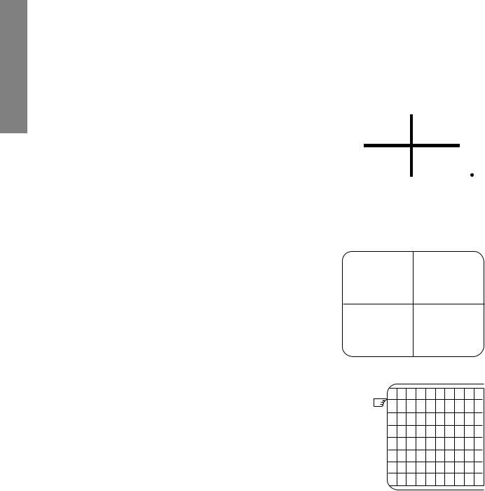
■ CIRCUMFERENCE CONVERGENCE:
* Perform correction in the following manner.
blue green
red
red/blue |
Xv bow-shaped deviation of convergence |
red/blue
blue
green
red
green
6-pole magnet |
Sub-4-pole magnet |
• Adjust coils and minimize deviation (The 27” unit has coils underneath it)
A |
|
D |
|
|
A |
|
D |
|
|
(Insertion position of correction |
|
|
|
||
|
blue |
piece) |
D |
A |
|
blue |
|
|
|
E |
B |
|
|
||
B |
green |
E |
B |
green |
E |
||
|
red |
|
F |
C |
|
red |
|
|
|
|
|
|
|
||
C |
|
F |
|
|
C |
|
F |
|
(Parts code:23 948 274) TC-S |
*Insert the correction piece between the |
|
(Parts code:23 948 464) |
|
||
|
S |
picture tube and the deflection yoke. |
|
N |
|
||
|
N |
|
|
|
|
S |
Bonded surface |
|
Bonded surface |
|
|
|
|
||
|
Blue color or blue mark |
|
|
|
Transparent |
|
|
Adjust VR 1 and minimize the deviation of YH. *Only 27", 30" and 32".
|
green |
|
|
green |
|
Red |
blue |
|
blue |
|
Red |
|
|
||||
Red |
blue |
|
blue |
|
Red |
|
|
||||
|
green |
|
|
green |
|
|
|
|
|
|
|
Adjust VR 2 (YHC) and minimize the deviation of YH.
|
green |
|
|
green |
|||
Red |
|
blue |
|
blue |
|
|
Red |
|
|
||||||
blue |
|
Red |
|
Red |
|
|
blue |
|
|
||||||
|
green |
|
|
green |
|||
Adjust VR 3 (YV) and minimize the deviation of YV.
|
|
|
|
Red |
|
|
|
|
|
blue |
|
|
|
|
green |
|
|
|
|
|
green |
|
|
|
|
|
|
|
|
|
||
|
|
|
|
blue |
|
|
|
|
|
Red |
|
|
|
|
blue |
|
|
|
|
|
Red |
|
|
|
|
green |
|
|
|
|
|
green |
|
|
|
|
|
|
|
|
|
||
|
|
|
|
Red |
|
|
|
|
|
blue |
|
|
|
|
|
|
|
|
|
|
|
Red green blue |
G |
blue green red |
|
blue green red |
H |
Red green blue |
||||
|
|
|
|
|
|
|
|
|
|
|
|
|
|
|
|
|
|
|
|
|
|
■ 30", 27", 32"
VR3 VR2 VR1
■ 34"
YV YHC
27" (Part No. 23 947 371)
32", 30" (Part No. 23 947 121)
34" (Part No. 23 993 080)
G |
|
H |
Perform correction by inserting the |
|
correction piece into the clear- |
||
|
|
|
|
|
|
|
ance of terminal board coils of |
|
|
|
the deflection yoke. |
|
|
|
|
|
|
|
Note: |
|
|
|
Perform insertion by turning the |
|
|
|
metal side to the terminal board |
|
|
|
side of the deflection yoke. |
SPECIFIC INFORMATIONS GENERAL ADJUSTMENTS
– 5 –

SPECIFIC INFORMATIONS GENERAL ADJUSTMENTS
SERVICE MODE
1. ENTERING TO SERVICE MODE |
|
|
|
|
|
|
|
|
|
|
|||
1) Press o button once on |
2) Press o button again to |
3) While pressing the o button, |
|||||||||||
|
Remote Control. |
|
keep pressing. |
press MENU button on TV set. |
|||||||||
|
|
|
|
|
|
|
|
|
|
|
|
|
|
|
|
|
|
|
|
|
|
|
|
|
|
S |
|
|
|
|
|
|
|
|
|
|
|
|
Item |
|
|
|
|
|
|
|
|
|
|
|
|
|
|
|
|
|
|
|
|
|
|
|
|
|
|
|
Data |
|
|
|
(or SOUND MUTE) |
|
|
|
|
|
|
|
|
|
|
|
|
|
|
|
|
|
|
|
|
|
|
|
|
|
|
|
|
|
|
|
|
|
|
|
(Service mode display) |
||||
2.DISPLAYING THE ADJUSTMENT MENU
1)Press MENU button on TV.
Service mode |
|
|
|
|
|
|
Adjustment mode |
||||
S |
|
|
Press |
|
|
|
|
|
|
Item |
|
|
|
|
|
|
|
|
|||||
|
|
|
|
|
|
|
|||||
|
|
|
|
|
|
|
|
Data |
|||
|
|
|
Press |
|
|
|
|
|
|
||
|
|
|
|
|
|
|
|
|
|
|
|
3.KEY FUNCTION IN THE SERVICE MODE
The following key entry during display of adjustment menu provides special functions.
A single horizontal line ON/OFF: |
- / - - button (on Remote) or a button (on TV) |
||||||||||
Test signal selection : |
a button (on Remote) |
||||||||||
Selection of the adjustment items : |
Channel s/t (on TV or Remote) |
||||||||||
Change of the data value : |
Volume ; +/– (on TV or Remote) |
||||||||||
Adjustment menu mode ON/OFF : |
MENU button (on TV) |
||||||||||
Initialization of the memory (QA02) : |
CALL + Channel button on TV (s) |
||||||||||
Reset the count of operating protect |
|
|
|
|
|
|
|
|
|
|
|
circuit to “00”: |
CALL + Channel button on TV (t) |
||||||||||
“RCUT” selection : |
1 button |
|
|
|
|
|
|
|
|
|
|
“GCUT” selection : |
2 button |
|
|
|
|
|
|
|
|
|
|
“BCUT” selection : |
3 button |
|
|
|
|
|
|
|
|
|
|
“CNTX” (or “SCNT”) selection : |
4 button |
|
|
|
|
|
|
|
|
|
|
“COLC” selection : |
5 button |
|
|
|
|
|
|
|
|
|
Color thickness correction |
|
|
|
|
|
|||||||
“TNTC” selection : |
6 button |
|
|
|
|
|
|
|
|
|
note: Displayed differently as shown below, de- |
Test audio signal ON/OFF (1kHz) : |
8 button |
|
|
|
|
|
|
|
|
|
pending on the setting of the receiving color |
Self diagnostic display ON/OFF : |
9 button |
|
|
|
|
|
|
|
|
|
system. |
|
|
|
|
|
|
|
|
|
|
|
COLP (PAL) |
COLC (NTSC)
COLS (SECAM)
CAUTION : Never try to perform initialization unless you have changed the memory IC.
– 6 –
4. SELECTING THE ADJUSTING ITEMS
1)Every pressing of CHANNEL s button in the service mode changes the adjustment items in the order of table-2. (t button for reverse order)
Refer to table-2 for preset data of adjustment mode. (See SETTING & ADJUSTING DATA on page 13)
5.ADJUSTING THE DATA
1)Pressing of VOLUME ; +/– button will change the value of data in the range from 00H to FFH. The variable range depends on the adjusting item.
6.EXIT FROM SERVICE MODE
1)Pressing POWER button to turn off the TV once.
■INITIALIZATION OF MEMORY DATA OF QA02
After replacing QA02, the following initialization is required.
1.Enter the service mode, then select any register item.
2.Press and hold the CALL button on the Remote, then press the CHANNEL s button on the TV. The initialization of QA02 has been complated.
3.Check the picture carefully. If necessary, adjust any adjustment item above. Perform “Auto search Memory” on the owner’s manual.
CAUTION: Never attempt to initialize the data unless QA02 has been replaced.
7.TEST SIGNAL SELECTION
1)Every pressing of a button on the Remote Control changes the built-in test patterns on screen as described below in SERVICE MODE.
Signal off  NTSC signals (5 patterns)
PAL signals (5 patterns) |
|
Signals |
Picture |
|
|
|
• Red raster
• Green raster
• Blue raster
• All White
• Black cross-hatch
* The signals marked with  are not usable to display in the Test signal for some model.
SPECIFIC INFORMATIONS GENERAL ADJUSTMENTS
– 7 –

SPECIFIC INFORMATIONS GENERAL ADJUSTMENTS
8.SELF DIAGNOSTIC FUNCTION
1)Press “9” button on Remote Control during display of adjustment menu in the service mode. The diagnosis will begin to check if interface among IC’s are executed properly.
2)During diagnosis, the following displays are shown.
SELF CHECK |
S |
2 3 x x x x x x
|
P O W E R |
: 0 0 0 |
B U S C O N T : O K |
||
|
B L O C K |
: U V V 1 V 2 V 3 |
|
|
V 4 |
Part number of microprocessor (QA01)
Operation number of protecting circuit ----“00” is normal.
When indication is other than “00”, overcurrent apts to flow, and circuit parts may possibly be damaged.
BUS CONT ----“OK” is normal.
When indication shows “Q uuu NG”, the device with the number may possibly be damaged.
BLOCK
UV : TV reception mode
V1 : VIDEO 1 input mode (a1)
V2 : VIDEO 2 input mode (a2)
V3 : VIDEO 3 input mode (a3)
V4 : VIDEO 4 input mode (a4)
Indicated color of mode now selected : Green and Red Indicated color of other modes : White
Green : Normal
Red : The microprocessor operates to provide judgement of no video signal. The red color is still indicated though the signal is input, failure may exist in input signal line including QV01.
– 8 –

DESIGN MODE
1. ENTERING TO DESIGN MODE |
|
|
|
|
|
|
|
|
|
|
|
|
|
|
|
|||
1) Select the Service mode. 2) |
While pressing o(or CALL) button on |
3) Press MENU button on TV. |
||||||||||||||||
|
|
|
|
Remote and press MENU button on TV. |
|
|
|
|
|
|
|
|
|
|||||
|
|
|
|
|
|
|
|
|
|
|
|
|
|
|
|
|
|
|
|
S |
|
|
|
|
D |
|
|
Press |
|
|
|
|
|
|
|
ITEM |
|
|
|
|
|
|
|
|
|
|
|
|
|
|
|
|
||||
|
|
|
|
|
|
|
||||||||||||
|
|
|
|
|
|
|
||||||||||||
|
|
|
|
|
|
|
|
|
Press |
|
|
|
|
|
|
|
DATA |
|
|
|
|
|
|
|
|
|
|
|
|
|
|
|
|
|
|||
|
|
|
|
|
|
|
|
|
|
|
|
|
|
|
|
|
|
|
|
|
|
|
|
|
|
|
|
|
|
|
|
|
|
|
|
|
|
|
|
|
|
|
|
|
|
|
|
|
|
|
|
|
|
|
|
|
|
|
|
|
|
|
(Design mode) |
|
|
|
|
|
|
|
(Adjustment mode) |
||||
When QA02 is initialized, items “OPT0”, “OPT1”, “OPT2” and “OPT3” of DESIGN MODE are set to the data of the representative model of this chassis family.
Therefore, because ON-SCREEN specification remains in the state of the representative of model. This model is required to reset the data of items “OPT0”, “OPT1”, “OPT2” and “OPT3”.
2. SELECTING THE ADJUSTING ITEMS
Every pressing of CHANNEL t button in the design mode changes the adjustment items in the order of table-3. (s button for reverse order)
Refer to table-3 for data of design mode.
(See SETTING & ADJUSTING DATA on page 13)
3. ADJUSTING THE DATA
Pressing of VOLUME s or t button will change the value of data.
SPECIFIC INFORMATIONS GENERAL ADJUSTMENTS
– 9 –
SPECIFIC INFORMATIONS GENERAL ADJUSTMENTS
ELECTRICAL ADJUSTMENTS
ITEM |
|
ADJUSTMENT PROCEDURE |
|
|
|
|
||
|
|
|
|
|
|
|
|
|
FOCUS VR ADJ |
1. |
Enter the service mode, then select any register item. |
|
|
|
|
||
|
2. |
Press the TV/VIDEO button on the Remote until the black cross-bar pattern ap- |
||||||
|
|
pears on the screen. |
|
|
|
|
|
|
|
3. |
Adjust the FOCUS control (on T461) for well defined scanning lines on the picture |
||||||
|
|
screen. |
|
|
|
|
|
|
|
|
|
|
|
|
|
|
|
SUB-BRIGHTNESS |
1. Set CONTRAST to minimum, |
and |
|
|
|
|
||
(BRTC) |
|
BRIGHTNESS to center by adjusting user |
|
|
|
|
||
|
|
controls. |
|
|
|
|
|
|
Note: Constrict the picture height |
2. |
Set the TV in service mode to get Black |
|
|
|
|
|
|
|
|
|
|
|
||||
until the vertical retrace line |
|
cross-bar of inside pattern. |
|
|
|
|
|
|
appears adjusting the item |
3. |
Select BRTC (brightness correction), and |
|
|
|
|
|
|
HIT (HEIGHT). |
|
adjust the ; – /+ button to reduce the |
|
|
|
|
|
|
|
|
|
|
|
|
|||
|
|
|
|
|
|
|||
|
|
value so that white portion of inside pat- |
|
|
|
|
|
|
|
|
tern slightly light. |
|
|
|
|
|
|
|
4. |
Adjust ; – /+ button to increase the data |
|
|
|
|
|
|
|
|
|
|
|
|
|||
|
|
|
|
|
|
|||
|
|
value of BRTC, and set it just before the |
|
|
|
|
||
|
|
difference between the belt of vertical re- |
|
|
|
|
||
|
|
Belt of vertical retrace |
||||||
|
|
trace and the border of black portion of |
||||||
|
|
inside pattern is visible. |
|
|
|
|
|
|
|
|
After that, return vertical height and con- |
|
|
|
|
||
|
|
trast. |
|
|
|
|
|
|
|
|
|
|
|
|
|
|
|
HORIZONTAL POSITION |
1. |
Set the TV in service mode, and get |
|
|
|
|
|
|
ADJUSTMENT (HPOS) |
|
black cross-bar signal with VIDEO |
|
|
|
|
|
|
|
|
button on remote hand unit. |
|
|
|
|
|
|
VERTICAL POSITION |
2. |
Select either HPOS (Horizontal pic- |
|
|
|
|
|
|
|
ture phase) or VPOS (Vertical picture |
|
|
|
|
|
|
|
ADJUSTMENT (VPOS) |
|
|
|
|
|
|
|
|
|
phase) with CHANNEL s, t buttons, |
|
|
|
|
|
|
|
|
|
and adjust horizontal or vertical pic- |
|
|
|
|
|
|
|
|
ture position in the center of screen |
|
|
|
|
|
|
|
|
with VOLUME ; – /+ buttons. |
|
|
|
|
|
|
|
|
|
|
|
|
|
|
|
VERTICAL AMPLITUDE |
1. |
Set the TV in service mode, and get |
|
|
|
|
|
|
ADJUSTMENT (HIT) |
|
black cross-hatch signal with VIDEO |
|
|
|
|
|
|
|
|
button on remote hand unit. |
|
|
|
|
|
|
|
2. |
Select HIT (Vertical amplitude) with |
The first |
|
|
|
|
|
|
|
CHANNEL s, t buttons, and adjust |
|
|
|
|
|
|
|
|
vertical amplitude with VOLUME |
|
|
|
|
|
|
|
|
; – /+ buttons so that vertical am- |
|
|
|
|
|
|
|
|
plitude lacks a little. |
|
|
|
|
|
|
|
3. |
Adjust vertical amplitude with VOL- |
|
|
|
|
|
|
|
|
UME ; – /+ buttons so that the first |
|
|
|
|
|
|
|
|
bar on cross-hatch signal touches |
|
|
|
|
|
|
|
|
edge of screen. |
|
|
|
|
|
|
|
|
|
|
|
|
|
|
|
– 10 –
ITEM |
|
ADJUSTMENT PROCEDURE |
|
|
|
WIDTH |
1. |
Call up the adjustment mode display, then select the item WID. |
(WID) |
2. |
Press the ; – /+ button to get the picture so the left and rightedges of raster |
|
|
begins to lack. |
|
3. |
Press the ; – /+ button to advance the data by 7 steps. |
|
Note : Check the horizontal picture position is correct. |
|
|
|
|
E-W PARABOLA |
1. |
Call up the adjustment mode display, then select the item PARA. |
(PARA) |
2. |
Press the abutton on Remote until the cross-hatch pattern appears on the screen. |
|
3. |
Press the ; – /+ button to make vertical lines straight as shown below. |
WHITE BALANCE |
|
|
|
|
|
|
|
|
|
|
1. |
Set Contrast to 40, and brightness to +20 by picture control. |
|||||||||
ADJUSTMENT |
2. |
Receive the Black and White pattern. |
|
|
||||||
• CUTOFF ADJUSTMENT |
3. |
Select RCUT, GCUT and BCUT with CHANNEL s, t buttons, to set individual |
||||||||
|
values to Initial reference data, and to set GDRV and BDRV to Initial reference |
|||||||||
(RCUT) |
|
data with VOLUME ; – /+ buttons. |
|
|
||||||
(GCUT) |
4. |
Press |
-/- - |
button on the remote control and rotate Screen VR to get one slight |
||||||
(BCUT) |
|
horizontal line on screen. |
|
|
||||||
• DRIVE ADJUSTMENT |
|
Note: Every pressing of |
-/- - |
button provides Horizontal line picture and Normal |
||||||
|
picture alternately. |
|
|
|||||||
(GDRV) |
5. |
Press |
|
-/- - |
button to release horizontal line picture, and select the two other colors |
|||||
(BDRV) |
|
which did not light in the above step with CHANNEL s, t buttons. Then tap VOL- |
||||||||
|
|
UME ; – /+ buttons so that three colors slightly light in the same level. |
||||||||
|
X To correct white balance in light area, |
Light area check |
||||||||
|
|
select GDRV and BDRV with CHANNEL |
||||||||
|
|
(to show white) |
||||||||
|
|
s, t buttons to adjust. |
||||||||
|
|
|
|
|||||||
|
X To correct white balance in dark area, |
|
|
|||||||
|
|
perform fine adjustment of RCUT, GCUT |
|
|
||||||
|
|
and BCUT. |
|
|
||||||
|
|
|
|
|
|
|
|
|
Dark area check |
|
|
|
|
|
|
|
|
|
|
(to show black) |
|
SPECIFIC INFORMATIONS GENERAL ADJUSTMENTS
– 11 –

SPECIFIC INFORMATIONS GENERAL ADJUSTMENTS
CIRCUIT CHECK
HIGH VOLTAGE CHECK
CAUTION: There is no HIGH VOLTAGE ADJUSTMENT on this chassis. Checking should be done following the steps below.
1.Connect an accurate high voltage meter to the second anode of the picture tube.
2.Turn on the receiver. Set the BRIGHTNESS and CONTRAST controls to minimum (zero beam current).
3.High voltage must be measured below (B) kV.
Refer to table-1 for high voltage (B).
(See SETTING & ADJUSTING DATA on page 13)
4. Vary the BRIGHTNESS control to both extremes to be sure the high voltage does not exceed the limit under any conditions.
– 12 –

CHAPTER 2 SPECIFIC INFORMATIONS
SETTING & ADJUSTING DATA

 SAFETY INSTRUCTIONS

|
|
29" |
34" |
HIGH VOLTAGE AT ZERO BEAM: |
(A) |
32.8 kV |
33.2 kV |
MAX HIGH VOLTAGE: |
(B) |
33.0 kV |
35.0 kV |
AC VOLTAGE |
(C) |
110~240 V |
110~240 V |
|
|
|
|
Table-1

 SERVICE MODE

ADJUSTING ITEMS AND DATAS IN THE SERVICE MODE:
Item |
Name of adjustment |
Preset |
29" |
34" |
|
|
|
|
|
RCUT |
R CUTOFF (B/W) |
40H |
← |
← |
GCUT |
G CUTOFF (B/W) |
40H |
← |
← |
BCUT |
B CUTOFF (B/W) |
40H |
← |
← |
GDRV |
G DRIVE |
35H |
← |
← |
BDRV |
B DRIVE |
35H |
← |
← |
CNTX |
CONTRAST MAX |
7FH |
← |
← |
BRTC |
SUB BRIGHTNESS CEN |
80H |
← |
← |
COLC |
COLOR CEN NTSC |
1AH |
← |
← |
TNTC |
SUB TINT CEN |
1FH |
1CH |
1CH |
COLP |
COLOR CEN PAL |
FBH |
← |
← |
COLS |
COLOR CEN SECAM |
1AH |
← |
← |
SCNT |
SUB CONTRAST FOR TV |
19H |
← |
← |
VOLS |
VOL SCART |
75H |
← |
← |
FVOL |
FM VOL PRE SCALE |
15H |
← |
← |
NVOL |
NICAM VOL PRE SCALE |
3CH |
← |
← |
NICL |
NICAM THRESHOLD LEVEL |
03H |
← |
← |
NICH |
NICAM THRESHOLD LEVEL |
0AH |
← |
← |
IDL |
IGR THRESHOLD LEVEL |
90H |
← |
← |
|
|
|
|
|
Item |
Name of adjustment |
Preset |
29" |
34" |
|
|
|
|
|
IDH |
IGR THRESHOLD LEVEL |
A0H |
← |
← |
EVOL |
Volume out data on Woofer |
03H |
← |
← |
HPOS |
operation |
|
|
32H |
H-POSITION DFS/100 |
32H |
34H |
||
VPOS |
V-POSITION DFS/100 |
80H |
88H |
80H |
HIT |
PICTURE HEIGHT DFS/100 |
40H |
48H |
40H |
VLIN |
V-LINEARITY DFS/100 |
12H |
0AH |
12H |
VSC |
V-S CORRECTION DFS/100 |
33H |
← |
← |
VPS |
V-BALANCE DFS/100 |
40H |
← |
← |
VCP |
V-COMPENSATION DFS/100 |
02H |
← |
← |
WID |
H-WIDTH DFS/100 |
59H |
55H |
59H |
PARA |
E-W PARABOLA DFS/100 |
1CH |
17H |
1CH |
CNR |
E-W CORNER DFS/100 |
19H |
17H |
19H |
TRAP |
TRAPEZIUM DFS/100 |
44H |
46H |
44H |
HCP |
H-COMPENSATION DFS/100 |
03H |
← |
← |
VFC |
V-ƒ CORRECTION DFS/100 |
08H |
← |
← |
SRY |
SECAM R-Y BLACK LEVEL |
07H |
← |
← |
SBY |
SECAM-B-Y BLACK LEVEL |
04H |
← |
← |
|
|
|
|
|
Table-2

 DESIGN MODE

ADJUSTING ITEMS AND DATAS IN THE DESIGN MODE:
Item |
Name of adjustment |
Preset |
Data |
Data |
|
Data |
29" |
34" |
|||
|
|
||||
OPT0 |
OPTION 0 |
02H |
← |
← |
|
OPT1 |
OPTION 1 |
42H |
← |
← |
|
OPT2 |
OPTION 2 |
04H |
← |
← |
|
OPT3 |
OPTION 3 |
FDH |
DFH |
DFH |
|
OPT4 |
OPTION 4 |
62H |
← |
← |
|
OPT5 |
OPTION 5 |
C8H |
C0H |
C0H |
Table-3
SPECIFIC INFORMATIONS GENERAL ADJUSTMENTS
– 13 –
SPECIFIC INFORMATIONS GENERAL ADJUSTMENTS
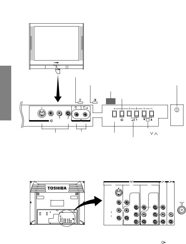
LOCATION OF CONTROLS
Front |
ON-TIMER indicator
POWER indicator |
q POWER switch |
Remote sensor
Input source selection
Behind the door
L/MONO |
R |
S-VIDEO |
VIDEO |
AUDIO |
(3) 
a(3) Video 3 input
Headphones jacks
terminals
(ø3.5 mm)
LMain sound l PIP sound
Headphones jacks
MENU |
CH |
Channel position t s
Menu
MENU
–;+ Volume – +
Menu < >
L : For private listening, connect headphones. The sound from the speakers will be cut off automatically. To adjust the volume, press the – ; + buttons.
l : Use this jack when listening to the sound of the sub-picture (Picture-in-Picture).
Back |
|
|
|
|
|
(1) |
(2) |
(4) |
(MONITOR) |
(FIXED) |
|
|
|
|
|
||
S-VIDEO |
|
|
|
|
|
|
COMPONENT |
COMPONENT |
|
|
|
|
VIDEO INPUT |
VIDEO INPUT |
|
|
|
|
|
(HD) |
|
|
|
VIDEO |
|
|
|
|
|
|
Y |
Y |
|
AUDIO |
|
L/MONO |
|
|
|
L |
|
|
|
|
|
|
|
AUDIO |
PB/ |
PB/ |
|
|
|
|
CB/ |
CB/ |
|
|
|
R |
|
|
|
R |
Antenna input |
|
|
|
|
||
|
PR/ |
PR/ |
|
|
|
|
|
|
|
||
|
CR/ |
CR/ |
|
|
|
a(1) Video 1 input terminals |
|
|
|
|
|
|
|
|
|
FIXED AUDIO output |
|
|
|
|
|
|
|
|
|
||
|
|
|
|
|
|
|
|
|
|
terminals |
a(2) Video 2 input/COMPONENT VIDEO INPUT terminals |
|
|
|
|
|
MONITOR output |
||||
|
|
|
|
|||||||
|
|
|
|
|
|
terminals |
||||
a (4) Video 4 input/COMPONENT VIDEO INPUT (HD) terminals
– 14 –
Loading...