


27AF44
SERVICE MANUAL
COLOR TELEVISION
27AF44
FILE NO. 050-200401
DOCUMENT CREATED IN JAPAN, Feb., 2004

SERVICING NOTICES ON CHECKING
6. AVOID AN X-RAY1. KEEP THE NOTICES
As for the places which need special attentions,
they are indicated with the labels or seals on the
cabinet, chassis and parts. Make sure to keep the
indications and notices in the operation manual.
3. USE THE DESIGNATED PARTS
5. TAKE CARE TO DEAL WITH THE
CATHODE-RAY TUBE
Safety is secured against an X-ray by consider-
ing about the cathode-ray tube and the high
voltage peripheral circuit, etc.
Therefore, when repairing the high voltage pe-
ripheral circuit, use the designated parts and
make sure not modify the circuit.
Repairing except indicates causes rising of high
voltage, and it emits an X-ray from the cathode-
ray tube.
Please include the following informations when you order parts. (Particularly the VERSION LETTER.)
1. MODEL NUMBER and VERSION LETTER
The MODEL NUMBER can be found on the back of each product and the VERSION LETTER can be
found at the end of the SERIAL NUMBER.
2. PART NO. and DESCRIPTION
You can find it in your SERVICE MANUAL.
HOW TO ORDER PARTS
Inferior silicon grease can damage IC's and transistors.
When replacing an IC's or transistors, use only specified silicon grease (YG6260M).
Remove all old silicon before applying new silicon.
IMPORTANT
2. AVOID AN ELECTRIC SHOCK
There is a high voltage part inside. Avoid an
electric shock while the electric current is
flowing.
The parts in this equipment have the specific
characters of incombustibility and withstand
voltage for safety. Therefore, the part which is
replaced should be used the part which has
the same character.
Especially as to the important parts for safety
which is indicated in the circuit diagram or the
table of parts as a mark, the designated
parts must be used.
4. PUT PARTS AND WIRES IN THE
ORIGINAL POSITION AFTER
ASSEMBLING OR WIRING
There are parts which use the insulation
material such as a tube or tape for safety, or
which are assembled in the condition that
these do not contact with the printed board.
The inside wiring is designed not to get closer
to the pyrogenic parts and high voltage parts.
Therefore, put these parts in the original
positions.
In the condition that an explosion-proof cathode-
ray tube is set in this equipment, safety is
secured against implosion. However, when
removing it or serving from backward, it is
dangerous to give a shock. Take enough care to
deal with it.
PERFORM A SAFETY CHECK AFTER
SERVICING
7.
Confirm that the screws, parts and wiring which
were removed in order to service are put in the
original positions, or whether there are the
portions which are deteriorated around the
serviced places serviced or not. Check the
insulation between the antenna terminal or
external metal and the AC cord plug blades.
And be sure the safety of that.
(INSULATION CHECK PROCEDURE)
1.
2.
3.
4.
Unplug the plug from the AC outlet.
Remove the antenna terminal on TV and turn
on the TV.
Insulation resistance between the cord plug
terminals and the eternal exposure metal
[Note 2] should be more than 1M ohm by
using the 500V insulation resistance meter
[Note 1].
If the insulation resistance is less than 1M
ohm, the inspection repair should be
required.
[Note 1]
If you have not the 500V insulation
resistance meter, use a Tester.
[Note 2]
External exposure metal: Antenna terminal
Earphone jack
A1-1

TABLE OF CONTENTS
SERVICING NOTICES ON CHECKING.....................................................................................
HOW TO ORDER PARTS ..........................................................................................................
IMPORTANT ...............................................................................................................................
TABLE OF CONTENTS..............................................................................................................
GENERAL SPECIFICATIONS....................................................................................................
DISASSEMBLY INSTRUCTIONS
1. REMOVAL OF ANODE CAP ...............................................................................................
2. REMOVAL AND INSTALLATION OF FLAT PACKAGE IC ................................................
SERVICE MODE LIST ................................................................................................................
CONFIRMATION OF HOURS USED .........................................................................................
WHEN REPLACING EEPROM (MEMORY) IC ..........................................................................
ELECTRICAL ADJUSTMENTS..................................................................................................
BLOCK DIAGRAMS ...................................................................................................................
PRINTED CIRCUIT BOARDS
MAIN ........................................................................................................................................
CRT/VM COIL..........................................................................................................................
SCHEMATIC DIAGRAMS
MICON .....................................................................................................................................
CHROMA .................................................................................................................................
DEFLECTION ..........................................................................................................................
POWER ...................................................................................................................................
SOUND ....................................................................................................................................
TUNER/STEREO.....................................................................................................................
AV ............................................................................................................................................
COMB/FILTER.........................................................................................................................
CRT/SVM.................................................................................................................................
WAVEFORMS .............................................................................................................................
MECHANICAL EXPLODED VIEWS...........................................................................................
MECHANICAL REPLACEMENT PARTS LIST .........................................................................
ELECTRICAL REPLACEMENT PARTS LIST...........................................................................
A1-1
A1-1
A1-1
A2-1
A3-1~A3-5
B1-1
B2-1, B2-2
C1-1
C1-1
C1-1
D-1~D-5
E-1, E-2
F-1~F-4
F-5, F-6
G-1, G-2
G-3, G-4
G-5, G-6
G-7, G-8
G-9, G-10
G-11, G-12
G-13, G-14
G-15, G-16
G-17, G-18
H-1, H-2
I-1, I-2
J1-1
J2-1~J2-10
A2-1
GENERAL SPECIFICATIONS
G-1 TV CRT CRT Size / Visual Size 27 inch / 676.0mmV
System CRT Type Flat
Deflection 106 degree
Magnetic Field BV/BH +0.45G/0.18G
Color System NTSC
Speaker 2 Speaker
Position Front Side
Size 1.8 x 3.9 Inch
Impedance 8 ohm
Sound Output MAX
5.0+5.0 W
10%(Typical)
4.0+4.0 W
NTSC3.58+4.43 /PAL60Hz No
G-2 Tuning Broadcasting System US System M
System Tuner and System 1Tuner
Receive CH Destination USA(W/ CATV)
Tuning System F-Synth
Input Impedance VHF/UHF 75 ohm
2 - 69, 4A, A-5 - A-1,
CH Coverage A - I, J - W, W+1 - W+84
Intermediate Picture(FP) 45.75MHz
Frequency Sound(FS) 41.25MHz
FP-FS 4.50MHz
Preset CH No
Stereo/Dual TV Sound Yes
Tuner Sound Muting Yes
G-3 Power Power Source AC 120V AC 60Hz
DC
Power Consumption at AC
135 W at AC 120 V 60 Hz
Stand by (at AC) 3 W at AC 120 V 60 Hz
Per Year -- kWh/Year
Protector Power Fuse Yes
Safety Circuit Yes
IC Protector(Micro Fuse) No
G-4 Regulation Safety UL/CSA
Radiation FCC/IC
X-Radiation DHHS/HWC
G-5 Temperature Operation +5oC ~ +40oC
Storage -20oC ~ +60oC
G-6 Operating Humidity Less than 80% RH
A3-1
GENERAL SPECIFICATIONS
G-7 On Screen Menu Yes
Display Menu Type Icon
Picture Yes
Contrast Yes
Brightness Yes
Color Yes
Tint Yes
Sharpness Yes
Sound Yes
Bass Yes
Treble Yes
Balance Yes
BBE On/Off Yes
Stable Sound On/Off Yes
Surround On/Off Yes
Set Up Yes
TV/CATV Yes
Auto CH Memory Yes
Add/ Delete Yes
Option
Yes
Language Yes
CH Label Yes
Favorite CH Yes
V-Chip Yes
Lock Yes
On/Off Timer Yes
Color Stream DVD/DTV Yes
Control Level Yes
Volume Yes
Brightness Yes
Contrast Yes
Color Yes
Tint Yes
Sharpness Yes
Tuning No
Bass Yes
Treble Yes
Balance Yes
Back Light No
Stereo,Audio Output,SAP Yes
Video Yes
Color Stream Yes
Channel(TV/Cable) Yes
CH Label Yes
Game Timer Yes
Sleep Timer Yes
Sound Mute Yes
V-chip Rating Yes
16: 9 Yes
G-8 OSD Language English French Spanish
G-9 Clock and Sleep Timer Max Time 120 Min
Timer Step
10 Min
On/Off Timer Program(On Timer / Off Timer) Yes
Wake Up Timer No
Timer Back-up (at Power Off Mode) more than -- Min Sec
A3-2
GENERAL SPECIFICATIONS
G-10 Remote Unit RC-GW
Control Glow in Dark Remocon Yes
Format Toshiba
Custom Code
TV:40-BF h
Power Source Voltage(D.C) 3V
UM size x pcs UM-4 x 2 pcs
Total Keys
50 Keys
Keys Power Yes
1 Yes
2 Yes
3 Yes
4 Yes
5 Yes
6 Yes
7 Yes
8 Yes
9 Yes
0 Yes
100 Yes
CH Up Yes
CH Down Yes
Volume Up Yes
Volume Down Yes
TV/Caption/Text Yes
CH1/CH2 Yes
TV/Video(TV/AV) Yes
CH RTN/CH ENT(Quick View) Yes
Sleep Yes
RE Call(Call) Yes
Reset Yes
Menu/Enter Yes
Mute Yes
Exit Yes
MTS(Audio Select) Yes
Fav.Up Yes
Fav.Down Yes
16: 9 Yes
Multi Brand Keys CH Up(VCR) Yes
CH Down(VCR) Yes
Pause/Still Yes
TV/VCR(VCR) Yes
FF Yes
Rew Yes
Rec Yes
Play Yes
Stop Yes
TV Yes
VCR Yes
Cable Yes
DVD Yes
CODE Yes
Volume Up(DVD) Yes
Volume Down(DVD) Yes
DVD CLEAR Yes
TOP MENU Yes
DVD MENU Yes
DISPLAY Yes
A3-3
GENERAL SPECIFICATIONS
G-11 Features Auto Degauss Yes
Auto Shut Off Yes
Canal+ No
CATV Yes
Anti-theft No
Rental No
Memory(Last CH) Yes
Memory(Last Volume) Yes
V-Chip Yes
Type
USA,Toshiba Type
BBE Yes
Auto Search No
CH Allocation No
SAP Yes
Just Clock Function No
CH Label Yes
VM Circuit Yes
Full OSD No
Premiere No
Comb Filter Yes
3 Lines
Auto CH Memory Yes
Hotel Lock No
Closed Caption Yes
Stable Sound Yes
FBT Leak Test Protect Yes
CH Lock Yes
Video Lock Yes
Game Timer (Max Time:120 Min) Yes
Energy Star No
Favorite CH Yes
Surround Yes
16:9 Mode Yes
G-12 Accessories Owner's Manual Language English / French
W/ Warranty Yes
Remote Control Unit Yes
Rod Antenna
No
Poles
Terminal
Loop Antenna
No
Terminal -
U/V Mixer
No
DC Car Cord (Center+)
No
Guarantee Card
No
Warning Sheet
No
Circuit Diagram
No
Antenna Change Plug
No
Service Station List
No
Important Safety Instruction
No
Dew/AHC Caution Sheet
No
AC Plug Adapter
No
Quick Set-up Sheet
No
Battery Yes
UM size x pcs UM-4 x 2
OEM Brand
No
AC Cord
No
AV Cord (2Pin-1Pin)
No
Registration Card (NDL Card) Yes
PTB Sheet
No
ESP Card Yes
300 ohm to 75 ohm Antenna Adapter
No
A3-4
GENERAL SPECIFICATIONS
G-13 Interface Switch Front Power Yes
System Select No
Main Power SW No
Sub Power No
Channel Up Yes
Channel Down Yes
Volume Up Yes
Volume Down Yes
Rear AC/DC No
TV/CATV Selector No
Degauss No
Main Power SW No
Indicator Power Yes(RED)
Stand-by No
On Timer No
Terminals Front Video Input = VIDEO3
RCA
Audio Input = VIDEO3
RCA x 2
Other Terminal
Head Phone
Rear Video Input(Rear1) = VIDEO1
RCA
Video Input(Rear2) = VIDEO2
RCA
Audio Input(Rear1) = VIDEO1
RCA x 2
Audio Input(Rear2) = VIDEO2
RCA x 2
Video Output
RCA
Audio Output
RCA x 2
Euro Scart
No
Color Stream
RCA x 3
S Input Yes
Diversity No
Ext Speaker No
DC Jack 12V(Center +) No
VHF/UHF Antenna Input
F Type
AC Outlet No
G-14 Set Size Approx. W x D x H (mm)
740 x 495 x 574.5
G-15 Weight Net (Approx.) 40.0 kg
( 88.2lbs)
Gross (Approx.) 46.5 kg
( 102.5lbs)
G-16 Carton Master Carton
No
Content ----
Sets
Material --
/--
Dimensions W x D x H(mm) -- x -- x --
Description of Origin
No
Gift Box Yes
Material Double/Brown
Dimensions W x D x H(mm) 850 x 620 x 665
Design As per Buyer's
Description of Origin Yes
Drop Test
Natural Dropping At 1 Corner / 2
Ed
g
es / 4 Surfaces
Height (cm) 40 (ORION SPEC:25)
Container Stuffing
156
Sets/40' container
G-17 Cabinet Material Cabinet Cabinet Front PS 94V0 DECABROM
Cabinet Rear PS 94V0 DECABROM
PCB Non-Halogen Demand
No
Eyelet Demand Yes
G-18 Environment Pb Free Lead-free Solder No
Cd Free No
A3-5
B1-1
1. REMOVAL OF ANODE CAP
Read the following NOTED items before starting work.
After turning the power off there might still be a potential
voltage that is very dangerous. When removing the
Anode Cap, make sure to discharge the Anode Cap's
potential voltage.
Do not use pliers to loosen or tighten the Anode Cap
terminal, this may cause the spring to be damaged.
*
*
REMOVAL
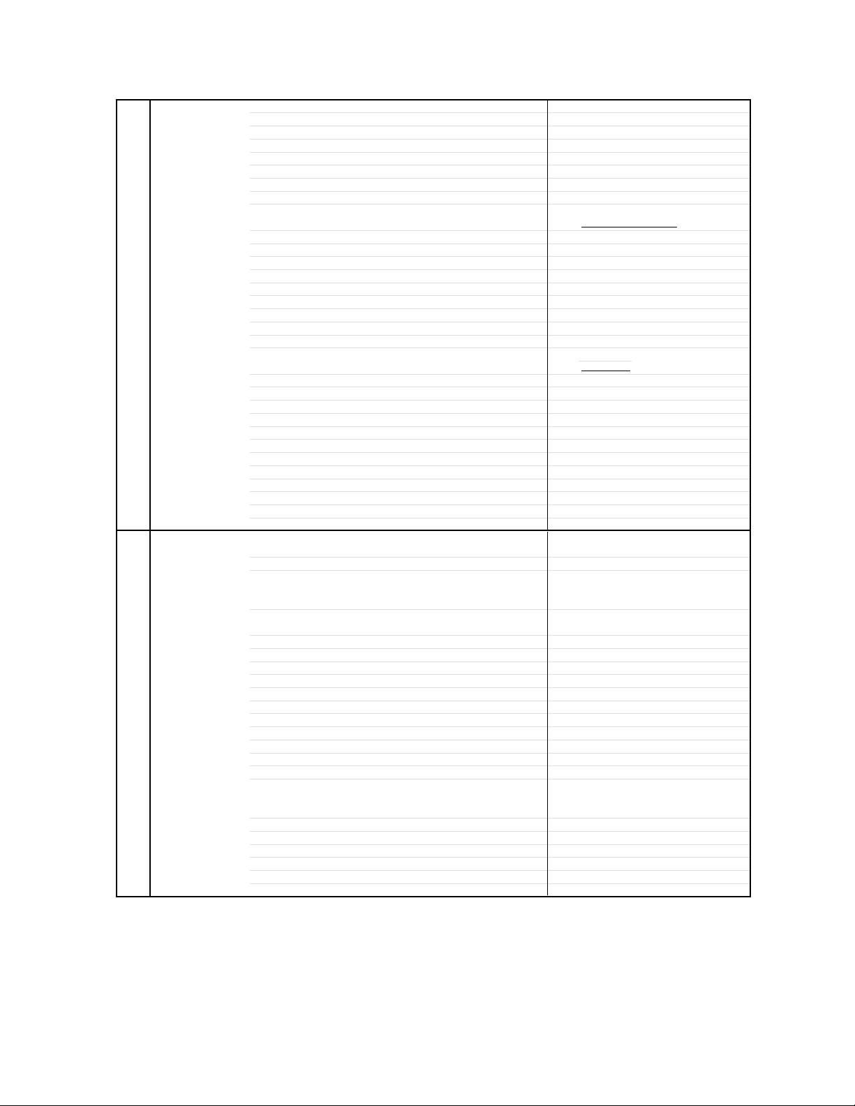
1. Follow the steps as follows to discharge the Anode Cap.
(Refer to Fig. 1-1.)
Connect one end of an Alligator Clip to the metal part of a
flat-blade screwdriver and the other end to ground.
While holding the plastic part of the insulated Screwdriver,
touch the support of the Anode with the tip of the
Screwdriver.
A cracking noise will be heard as the voltage is discharged.
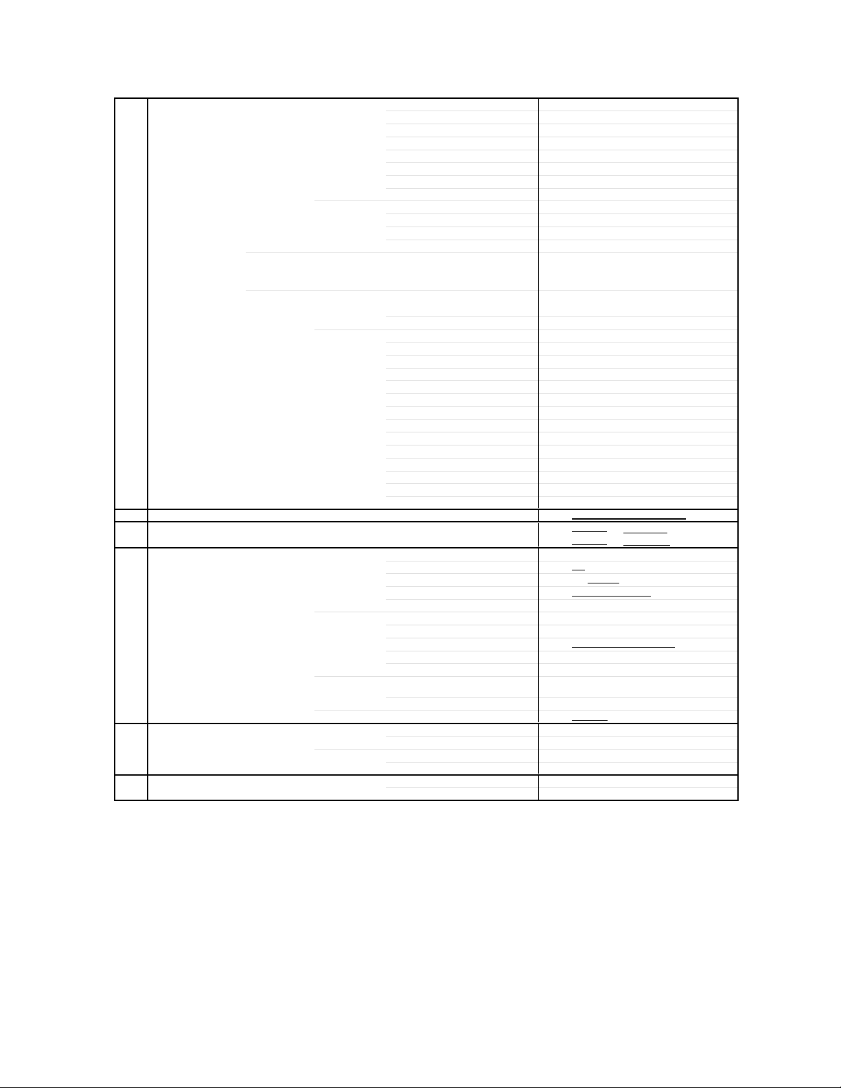
Flip up the sides of the Rubber Cap in the direction of the
arrow and remove one side of the support.
(Refer to Fig. 1-2.)
2.
DISASSEMBLY INSTRUCTIONS
GND on the CRT
Screwdriver
Alligator Clip
Support
CRT
GND on the CRT
Rubber Cap
CRT
Support
Fig. 1-1
Fig. 1-2
3. After one side is removed, pull in the opposite direction to
remove the other.
NOTE
Take care not to damage the Rubber Cap.
INSTALLATION
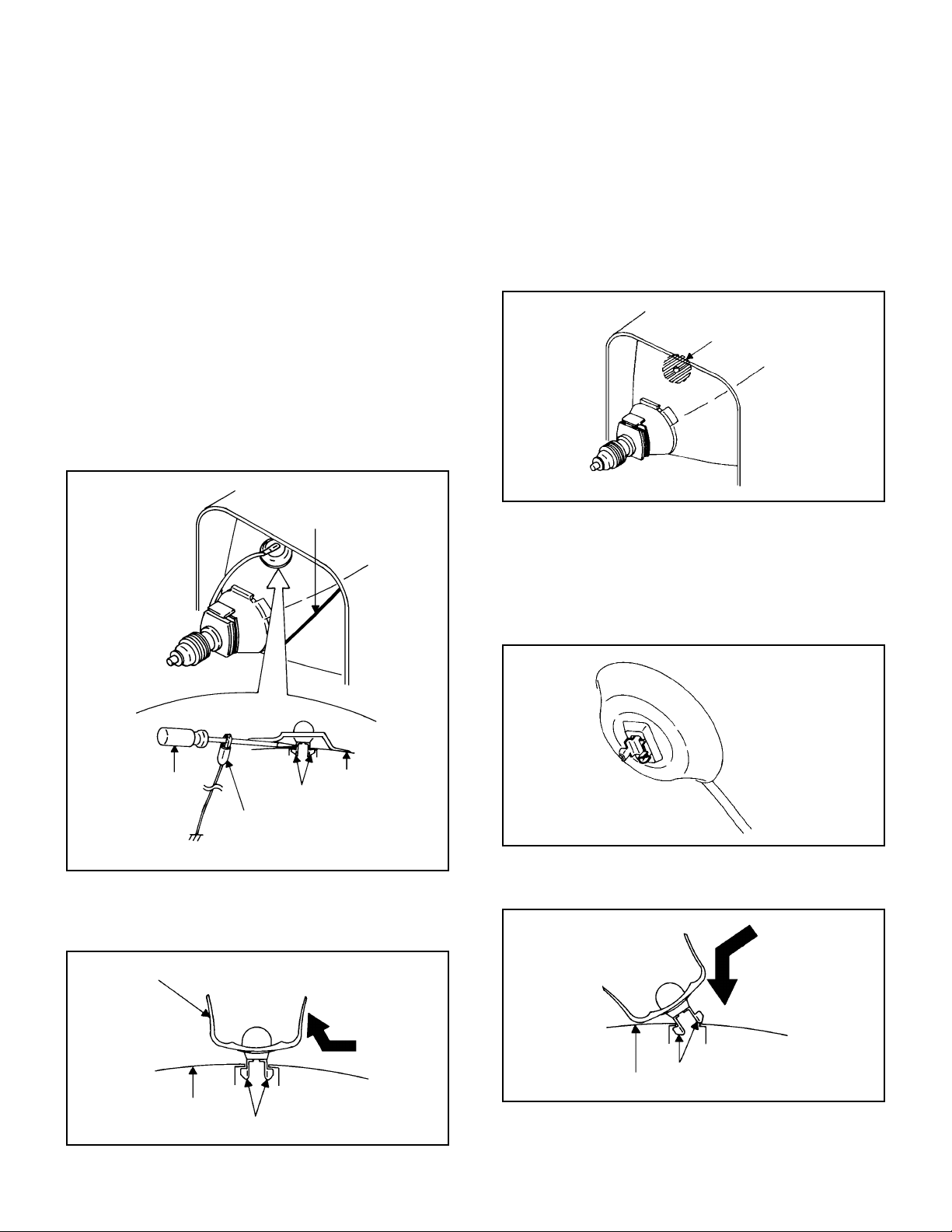
1. Clean the spot where the cap was located with a small
amount of alcohol. (Refer to Fig. 1-3.)
Location of Anode Cap
Fig. 1-3
NOTE
Confirm that there is no dirt, dust, etc. at the spot where
the cap was located.
2.
3.
Arrange the wire of the Anode Cap and make sure the
wire is not twisted.
Turn over the Rubber Cap. (Refer to Fig. 1-4.)
Fig. 1-4
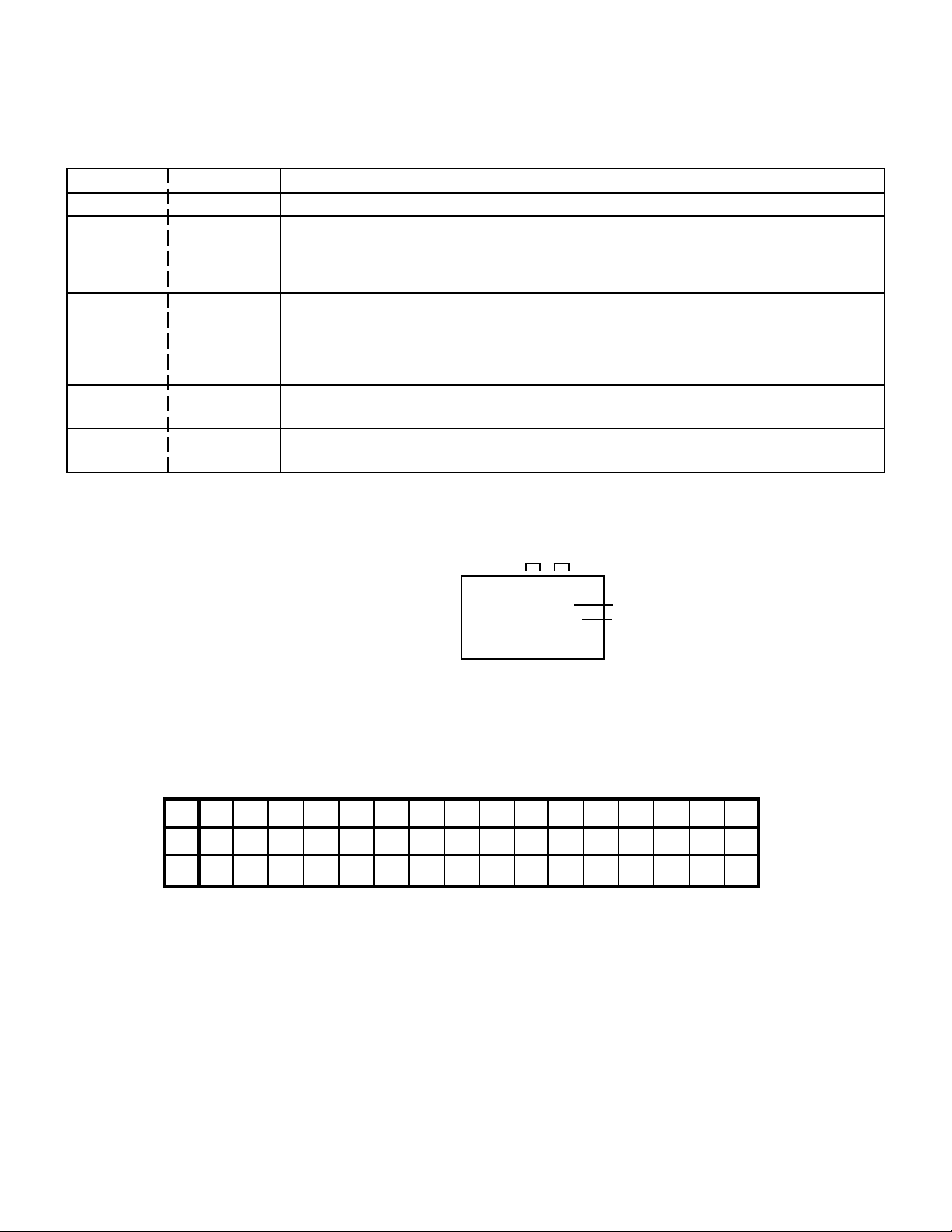
4. Insert one end of the Anode Support into the anode button,
then the other as shown in Fig. 1-5.
5.
6.
Confirm that the Support is securely connected.
Put on the Rubber Cap without moving any parts.
CRT
Support
Fig. 1-5

B2-1
Masking Tape
(Cotton Tape)
DISASSEMBLY INSTRUCTIONS
2.
REMOVAL
IC
Put the Masking Tape (cotton tape) around the Flat
Package IC to protect other parts from any damage.
(Refer to Fig. 2-1.)
1.
Fig. 2-1
NOTE
REMOVAL AND INSTALLATION OF
FLAT PACKAGE IC
Some ICs on the PCB are affixed with glue, so be
careful not to break or damage the foil of each IC leads
or solder lands under the IC when removing it.
NOTE
Masking is carried out on all the parts located within 10
mm distance from IC leads.
Blower type IC
desoldering machine
IC
Heat the IC leads using a blower type IC desoldering
machine. (Refer to Fig. 2-2.)
2.
Fig. 2-2
NOTE
Do not add the rotating and the back and forth
directions force on the IC, until IC can move back and
forth easily after desoldering the IC leads completely.
When IC starts moving back and forth easily after
desoldering completely, pickup the corner of the IC using a
tweezers and remove the IC by moving with the IC
desoldering machine. (Refer to Fig. 2-3.)
3.
Blower type IC
desoldering
machine
IC
Fig. 2-3
Tweezers
Peel off the Masking Tape.4.
Absorb the solder left on the pattern using the Braided
Shield Wire. (Refer to Fig. 2-4.)
5.
NOTE
Do not move the Braided Shield Wire in the vertical
direction towards the IC pattern.
Braided Shield Wire
Soldering Iron
Fig. 2-4
IC pattern

B2-2
DISASSEMBLY INSTRUCTIONS
Supply soldering
from upper position
to lower position
IC
Supply the solder from the upper position of IC leads
sliding to the lower position of the IC leads.
(Refer to Fig. 2-6.)
2.
Fig. 2-6
Soldering IronSolder
IC
Absorb the solder left on the lead using the Braided Shield
Wire. (Refer to Fig. 2-7.)
3.
Fig. 2-7
Soldering Iron
Braided Shield Wire
NOTE
Do not absorb the solder to excess.
IC
When bridge-soldering between terminals and/or the
soldering amount are not enough, resolder using a Thin-tip
Soldering Iron. (Refer to Fig. 2-8.)
4.
Fig. 2-8
Thin-tip Soldering Iron
NOTE
When the IC leads are bent during soldering and/or
repairing, do not repair the bending of leads. If the
bending of leads are repaired, the pattern may be
damaged. So, always be sure to replace the IC in this
case.
Finally, confirm the soldering status on four sides of the IC
using a magnifying glass.
Confirm that no abnormality is found on the soldering
position and installation position of the parts around the IC.
If some abnormality is found, correct by resoldering.
5.
Solder temporarily
Soldering Iron
INSTALLATION
Take care of the polarity of new IC and then install the new
IC fitting on the printed circuit pattern. Then solder each
lead on the diagonal positions of IC temporarily.
(Refer to Fig. 2-5.)
1.
Fig. 2-5
Solder temporarily
SERVICE MODE LIST
This unit provided with the following SERVICE MODES so you can repair, examine and adjust easily.
To enter the Service Mode, press both set key and remote control key for more than 1 second.
Set Key
Remocon Key Operations
VOL. (-) MIN
0
Releasing of V-CHIP PASSWORD.
VOL. (-) MIN
1
Initialization of the factory.
NOTE:
Do not use this for the normal servicing.
If you set a factory initialization, the memories are reset such as the channel setting,
and the POWER ON total hours.
VOL. (-) MIN
6
POWER ON total hours is displayed on the screen.
Refer to the "CONFIRMATION OF HOURS USED".
Can be checked of the INITIAL DATA of MEMORY IC.
Refer to the "WHEN REPLACING EEPROM (MEMORY) IC".
VOL. (-) MIN 8
Writing of EEPROM initial data.
NOTE: Do not use this for the normal servicing.
VOL. (-) MIN
Display of the Adjustment MENU on the screen.
Refer to the "ELECTRICAL ADJUSTMENT" (On-Screen Display Adjustment).
9
CONFIRMATION OF HOURS USED
POWER ON total hours can be checked on the screen. Total hours are displayed in 16 system of notation.
NOTE: If you set a factory initialization, the total hours is reset to "0".
1.
2.
3.
Set the VOLUME to minimum.
Press both VOL. DOWN button on the set and Channel
button (6) on the remote control for more than 1 second.
After the confirmation of using hours, turn off the power.
ADDRESS DATA
INIT 00 50
CRT ON 0010
FIG. 1
Initial setting content of MEMORY IC.
POWER ON total hours.
= (16 x 16 x 16 x thousands digit value)
+ (16 x 16 x hundreds digit value)
+ (16 x tens digit value)
+ (ones digit value)
C-1
WHEN REPLACING EEPROM (MEMORY) IC
If a service repair is undertaken where it has been required to change the MEMORY IC, the following steps should be taken to
ensure correct data settings while making reference to TABLE 1.
Table 1
1.
2.
3.
4.
5.
6.
7.
8.
9.
10.
11.
The unit will now have the correct DATA for the new MEMORY IC.
Enter DATA SET mode by setting VOLUME to minimum.
Press both VOL. DOWN button on the set and Channel button (6) on the remote control for more than 1 second.
ADDRESS and DATA should appear as FIG 1.
ADDRESS is now selected and should "blink". Using the VOL. UP/DOWN button on the remote, step through the ADDRESS
until required ADDRESS to be changed is reached.
Press ENTER to select DATA. When DATA is selected, it will "blink".
Again, step through the DATA using VOL. UP/DOWN button until required DATA value has been selected.
Pressing ENTER will take you back to ADDRESS for further selection if necessary.
Repeat steps 3 to 6 until all data has been checked.
When satisfied correct DATA has been entered, turn POWER off (return to STANDBY MODE) to finish DATA input.
After the data input, set to the initializing of shipping.
Turn POWER on.
Press both VOL. DOWN button on the set and Channel button (1) on the remote control for more than 1 second.
After the finishing of the initializing of shipping, the unit will turn off automatically.
NOTE: No need setting for after INI 1F due to the adjustment value.
50 E8 0A 44 5E B3 24 B7 3D AC
+0 +1 +2 +3 +4 +5 +6 +7 +8 +9 +A +B +C +D +E +F
INI
70 00 00 00 00 06 00 3F 0F10 00 0D E2 A8 21 42 00
00 AA 04 80 80 80 59

ELECTRICAL ADJUSTMENTS
D-1
FUNCTION
CONTRAST CENT
CONTRAST MIN
COLOR MAX
COLOR CENTER
COLOR MIN
TINT
SHARPNESS
Cb DELAY FINE
Cr DELAY FINE
Cb PEDESTAL ADJ
Cr PEDESTAL ADJ
E/W PARABOLA
E/W CORNER
E/W TRAPEZIUM
LEVEL
SEPARATION1
SEPARATION2
READ DATA
1. ADJUSTMENT PROCEDURE
Read and perform these adjustments when repairing the
circuits or replacing electrical parts or PCB assemblies.
CAUTION
•
•
•
•
Use an isolation transformer when performing any service
on this chassis.
Before removing the anode cap, discharge electricity
because it contains high voltage.
When removing a PCB or related component, after
unfastening or changing a wire, be sure to put the wire
back in its original position.
When you exchange IC and Transistor for a heat sink,
apply the silicon grease on the contact section of the heat
sink. Before applying new silicon grease, remove all the
old silicon grease. (Old grease may cause damages to the
IC and Transistor.)
2. BASIC ADJUSTMENTS
Prepare the following measurement tools for electrical
adjustments.
2-1: CONSTANT VOLTAGE
1.
2.
3.
4.
Place the set with Aging Test for more than 5 minutes.
Set condition is AV MODE without signal.
Connect the digital voltmeter to the TP003.
Adjust the VR502 until the digital voltmeter is 135 ± 0.5V.
1. Oscilloscope
2. Digital Voltmeter
3. Multi-sound Generator
4. Pattern Generator
On-Screen Display Adjustment
1. In the condition of NO indication on the screen.
Press the VOL. DOWN button on the set and the Channel
button (9) on the remote control for more than 1 second to
appear the adjustment mode on the screen as shown in
Fig. 1-1.
Fig. 1-1
3.
4.
Use the Channel UP/DOWN button or Channel button
(0-9) on the remote control to select the options shown
in Fig. 1-2.
Press the MENU button on the remote control to end the
adjustments.
FUNCTION
OSD H
CUT OFF
H. VCO
H. PHASE
AFC GAIN
V. SHIFT
H. SIZE
V. SIZE
V. LINEARITY
VS CORRECTION
DRIVE R
DRIVE B
R CUT OFF
G CUT OFF
B CUT OFF
BRIGHT MAX
BRIGHT CENT
BRIGHT MIN
CONTRAST MAX
NO.
00
01
02
03
04
05
06
07
08
09
10
11
12
13
14
15
16
17
18
Fig. 1-2
NO.
19
20
21
22
23
24
25
26
27
28
29
30
31
32
33
34
35
88
TV
00 OSD 28
2-4: FOCUS
1.
2.
3.
Receive the monoscope pattern.
Turn the Focus Volume fully counterclockwise once.
Adjust the Focus Volume until picture is distinct.
2-3: WHITE BALANCE
NOTE: Adjust after performing CUT OFF adjustment.
1.
2.
3.
4.
5.
6.
7.
Place the set with Aging Test for more than 10 minutes.
Receive the gray scale pattern from the Pattern Generator.
Using the remote control, set the brightness and contrast
to normal position.
Activate the adjustment mode display of Fig. 1-1 and
press the channel button (12) on the remote control to
select “R. BIAS”.
Press the CH. UP/DOWN button on the remote control to
select the “R. BIAS”, “G. BIAS”, “B. BIAS”, “B. DRIVE” or
“G. DRIVE”.
Adjust the VOL. UP/DOWN button on the remote control
to whiten the R. BIAS, G. BIAS, B. BIAS, B. DRIVE, and
G. DRIVE at each step tone sections equally.
Perform the above adjustments 5 and 6 until the white
color is looked like a white.
2-2: CUT OFF
1.
2.
3.
Place the set with Aging Test for more than 15 minutes.
Activate the adjustment mode display of Fig. 1-1 and
press the channel button (01) on the remote control to
select "CUT OFF".
Adjust the Screen Volume until a dim raster is obtained.
2-5: HORIZONTAL PHASE
1.
2.
3.
4.
Receive the monoscope pattern.
Using the remote control, set the brightness and contrast
to normal position.
Activate the adjustment mode display of Fig. 1-1 and
press the channel button (03) on the remote control to
select “H. PHAS”.
Press the VOL. UP/DOWN button on the remote control
until the SHIFT quantity of the OVER SCAN on right and
left becomes minimum.

ELECTRICAL ADJUSTMENTS
D-2
2-8: VERTICAL SIZE
1.
2.
3.
4.
Receive the monoscope pattern.
Using the remote control, set the brightness and contrast
to normal position.
Activate the adjustment mode display of Fig. 1-1 and
press the channel button (07) on the remote control to
select “V. SIZE”.
Press the VOL. UP/DOWN button on the remote control
until the SHIFT quantity of the OVER SCAN on upside and
downside becomes 9 ± 2%.
2-7: VERTICAL POSITION
1.
2.
3.
Receive the monoscope pattern.
Using the remote control, set the brightness and contrast
to normal position.
Adjust the VR401 until the horizontal line becomes fit to
the notch of the shadow mask.
2-9: VERTICAL LINEARITY
NOTE: Adjust after performing adjustments in section 2-8.
After the adjustment of Vertical Linearity, reconfirm
the Vertical Position and Vertical Size adjustments.
Receive the monoscope pattern.
Using the remote control, set the brightness and contrast
to normal position.
Activate the adjustment mode display of Fig. 1-1 and
press the channel button (08) on the remote control to
select “V. LIN”.
Press the VOL. UP/DOWN button on the remote control
until the SHIFT quantity of the OVER SCAN on upside and
downside becomes minimum.
1.
2.
3.
4.
2-6: HORIZONTAL SIZE
1.
2.
3.
4.
Receive the monoscope pattern.
Using the remote control, set the brightness and contrast
to normal position.
Activate the adjustment mode display of Fig. 1-1 and
press the channel button (06) on the remote control to
select “H. SIZE”.
Press the VOL. UP/DOWN button on the remote control
until the SHIFT quantity of the OVER SCAN on right and
left becomes 10%.
2-13: SEPARATION 1, 2
1.
2.
3.
4.
5.
Set the multi-sound signal generator for each different
L-ch and R-ch frequency (Ex. L-ch=2KHz, R-ch=400Hz)
and receive the RF.
Connect the oscilloscope to the Audio Out Jack.
Activate the adjustment mode display of Fig. 1-1 and
press the channel button (34) on the remote control to
select “SEP 1”.
Press the VOL. UP/DOWN button on the remote control
to adjust it until the audio output wave becomes a fine
sine wave.
Press the CH UP button once the set to "SEP 2" mode.
Then perform the above adjustment 4.
Method (1)
1.
2.
3.
4.
5.
6.
7.
8.
9.
Set the multi-sound signal generator L-ch=1KHz, R-ch
=Non input and receive the RF.
Connect the oscilloscope to the Audio Out Jack (R-ch).
Press the AUDIO SELECT button on the remote control
to set to the stereo mode.
Activate the adjustment mode display of Fig. 1-1 and
press the channel button (34) on the remote control to
select “SEP 1”.
Press the VOL. UP/DOWN button on the remote control
to adjust it until the R-ch output becomes minimum.
Set the multi-sound signal generator L-ch=Non input,
R-ch=1KHz and receive the RF.
Connect the oscilloscope to the Audio Out Jack (L-ch).
Activate the adjustment mode display of Fig. 1-1 and
press the channel button (35) on the remote control to
select “SEP 2”.
Press the VOL. UP/DOWN button on the remote control
to adjust it until the L-ch output becomes minimum.
Method (2)
Please do the method (1) or method (2) adjustment.
2-10: LEVEL
1.
2.
3.
4.
Receive the VHF HIGH (70dB).
Connect the AC voltmeter to pin 6 of CP101.
Activate the adjustment mode display of Fig. 1-1 and
press the channel button (33) on the remote control to
select "LEVEL".
Press the VOL. UP/DOWN button on the remote
control until the AC voltmeter is 75 ± 2mV.
2-11: CORNER
1.
2.
3.
4.
Receive the crosshatch signal from the Pattern Generator.
Using the remote control, set the brightness and contrast
to normal position.
Activate the adjustment mode display of Fig. 1-1 and
press the channel button (31) on the remote control to
select “CORNER”.
Press the VOL. UP/DOWN button on the remote control
until the right and left vertical lines are straight.
2-12: TRAPEZIUM
1.
2.
3.
4.
Receive the crosshatch signal from the Pattern Generator.
Using the remote control, set the brightness and contrast
to normal position.
Activate the adjustment mode display of Fig. 1-1 and
press the channel button (32) on the remote control to
select “TRAPEZIUM”.
Press the VOL. UP/DOWN button on the remote control
until the both vertical lines of the screen become parallel.
 Loading...