


 Loading...
File No. SME05001100
R05072188300-TTEC
Ver00_2005-11

© 2005 TOSHIBA TEC CORPORATION
All rights reserved
Revision Record
|
|
|
|
|
File No. SME05001100 |
|
Date |
|
Rev.No |
Item |
Descriptions |
|
Remarks |
November, |
2005 |
00 |
--- |
Issue of the first version |
|
|
|
|
|
|
|
|
|
|
|
|
|
|
|
|
|
|
|
|
|
|
|
|
|
|
|
|
|
|

Purpose of the Imaging Manual
The Imaging Manual is intended for customers using the Toshiba e-STUDIO281c/351c/451c with a variety of specific needs and inquiries for high image quality, such as:
xHow to obtain a clearer copy image
xHow to maintain the current image quality
xHow to make the text look sharper on the copy
The Toshiba MFPs are factory-configured to provide image quality settings that satisfy the majority of customers. However, these settings may not be necessarily optimal for all specific needs from customers. Proper image quality adjustments can satisfy such needs. Most of the adjustments described in this manual must be performed by a service technician, but a few of them can also be performed by the customer.
It is strongly recommended that this manual be fully utilized by not only the service technician, but also the sales representative, who also has opportunities of obtaining customer feedback on the image quality. This manual helps the sales representative to study and comprehend what kind of customer needs for the image quality can be satisfied, to make a proposal to the customer for improving image quality, and to communicate the customers needs with ease to the service technician. In addition, this manual is expected to facilitate the marketing of the Toshiba MFPs to prospective customers that have specific demand for image quality and the expansion of sales.
The adjustments described in this manual are all based on the needs of actual customers. Meeting their specific needs will increase their satisfaction.
Please remember to read "Cautions after the completion of the adjustment," which you must pay close attention to, after the completion of the adjustment.
Precautions in Servicing
•For adjustments to be performed by the service technician, the cautions mentioned in the Service Manual must be stringently followed. The adjustments must be performed by a qualified service technician who has completed the service training course.
•The default values mentioned in this manual may be different from the actual ones, due to the timing of shipping (firmware version). But note that the values recommended and acceptable value range mentioned in this manual remain the same.
Purpose of the Imaging Manual
Icons
The following icons used in this manual denotes the following:
: • Copy ——— |
An adjustment having an effect on copying in Black mode (excluding |
|
Image smoothing mode) |
• Printer ——– |
An adjustment having an effect on black-and-white printing |
*The adjustment will be effective, if "Mono" is selected from among the "Color" options on the Windows printer driver or if "Mono" is selected from among the "Color Resolution Type" options on the Macintosh printer driver.
•Scan ——— An adjustment having an effect on scanning in Black mode
|
: |
• Copy ——–– |
An adjustment having an effect on copying in Image smoothing mode in |
|
|||
|
|
|
Black mode |
|
|
• Scan ——— An adjustment having an effect on scanning in Gray scale mode |
|
|
: |
• Copy ——— An adjustment having an effect on copying in Full color mode |
|
|
|||
|
|
• Printer ——– |
An adjustment having an effect on full-color printing |
PCL5c
PCL6
PS3
Mac
Scan to Box
Copy to Box
Print to Box
Fax to Box
*The adjustment will be effective, if "Automatic" is selected from among the "Color" options on the Windows printer driver or if "Color" is selected from among the "Color Resolution Type" options on the Macintosh printer driver.
•Scan ——— An adjustment having an effect on scanning in Full color mode
:• Copy ——— An adjustment having an effect on copying in Auto color mode
• Scan ——— An adjustment having an effect on scanning in Auto color mode
:An adjustment having an effect on printing on the Windows PCL5c emulation printer driver
:An adjustment having an effect on printing on the Windows PCL6 emulation printer driver
:An adjustment having an effect on printing on the Windows PS3 emulation printer driver
:An adjustment having effect on printing on the Macintosh printer driver
:An adjustment having an effect on the image stored in the e-Filing box by the scanning functions (including Scan to Box, Scan to File and Scan to E-mail)
:An adjustment having an effect on the image stored in the e-Filing box by the copying functions (Copy to Box)
:An adjustment having an effect on the image stored in the e-Filing box by the printing functions (Print to Box)
:An adjustment having an effect on the image stored in the e-Filing box by the Fax and Internet Fax functions (including Received Fax to Box and Received Internet Fax to Box)

Table of Contents
1.General Adjustments – Copying, Printing and e-Filing (Output from Box)
1.1To Obtain a Darker Image
1.2To Achieve the Image Quality Most Suitable for Paper Used
1.2.1To Adjust the Blurred or Grained Image
1.2.2To Adjust the Light Image at the Trailing Edge/Splattering of Toner
1.3To Minimize Variations in the Image Quality after Power-on (To optimally program image quality control)
1.4To Minimize Variations in the Image Quality under the Operating Conditions (To optimally program image quality control)
1.5To Correct Out-of-Register Colors
1.5.1Color Registration Control Procedure 1: To Correct Out-of-register colors on A3/LD-sized Paper with Test Print Pattern 63 (05-63)
1.5.2Color Registration Control Procedure 1: To Correct Out-of-register colors on A4/LT -sized Paper with Test Print Pattern 68 (05-68)
1.5.3Color Registration Control Procedure 2: To Correct Out-of-register colors with Test Print Pattern 64 (05-64)
2.Copier-specific Adjustments
2.1To Sharply Copy Light Text or Thin Lines (To darken handwritten text or thin lines in the graphic image)
2.1.1To Adjust the Copy Image Quality in Black Mode
2.1.2To Adjust the Copy Image Quality in Full Color Mode
2.1.3To Adjust the Copy Image Quality in Auto Color Mode
2.2To Closely Match with the Color Balance of the Original
2.3To Improve the Reproducibility of Gray
2.4To Copy in Vivid Colors
2.5To Make the Pale Area of the Original Look Darker and Sharper (To improve the highlight reproducibility)
2.6To Eliminate the Background Color
2.6.1To Adjust the Copy Image Quality in Black Mode
2.6.2To Adjust the Copy Image Quality in Full Color Mode
2.7To Avoid Copying the Image Seen through the Back of the Page Printed on Thin Paper
2.7.1To Adjust the Copy Image Quality in Black Mode
2.7.2To Adjust the Copy Image Quality in Full Color Mode
2.8To Eliminate Moiré
2.9To Copy Sharply (To enhance sharpness)
2.10To Make Photo Edges Look Softer
2.11To Make Solid Filled Bold Text (Logo) Highly Colored
2.11.1To Adjust the Copy Image Quality of a Black Logo
2.11.2To Adjust the Copy Image Quality of a Colored Logo
2.12To Sharply Contrast the Hues of Highlighters on the Copy
2.13To Obtain a Good Color Balance on Thick Paper
2.14To Obtain Smooth Gray-scale Photo Images
2.15To Change the Threshold in Auto Color Mode
(To change the threshold between Full color mode and Black mode to meet the user’s needs)
i

Table of Contents
2.16To Clearly Copy Text (To adjust the density of text)
2.16.1To Adjust the Copy Image Quality in Black Mode
2.16.2To Adjust the Copy Image Quality in Full Color Mode
2.17To Adjust the Twin Color Copy Image Quality (To adjust the image quality in red and black mode)
2.17.1To Adjust the Reproducibility of Black in Red and Black Mode
2.17.2To Adjust the Tint of Red in Red and Black Mode
2.18To Adjust the Image Quality Scanned from the RADF
3.Printer-specific Adjustments
3.1To Maintain a Steady Color Balance
3.2To Obtain the Desired Color Balance
3.3To Closely Match with the Color Balance on the Monitor
3.4To Maintain a Uniform Gray Hue (To Maintain consistency in Gray among Text, Photos and Graphics)
3.5To Easily Adjust the Overall Brightness
3.6To Easily Adjust the Overall Saturation
3.7To Clearly Print Light-colored Thin Lines or Text
3.8To Clearly Print Thin Lines/Double Lines
3.9To Decrease the Image Density and Save Toner (To Print in Toner Save Mode)
3.10To Adjust the Image Density in Toner Save Mode
3.11To Print Illegible Gray or Colored Text in Black
3.12To Ignore Blank Pages for Printing
3.13To Sharply Print Black Text
4.e-Filing-specific Adjustments
4.1To Clearly Store the B/W Image in Auto Color Mode
4.2To Store the Original, while Reducing the File Size
4.3To Store the Color Photo Image, while Minimizing Moiré
4.4To Store the B/W Original with Photos and Text with the High Density (To change the density in Copy to Box)
4.5To Match with the Color Balance on the Original (To adjust the color balance in Print to Box)
4.6To Scan and Print, while Minimizing Moiré
4.7To Finely Print the Image Stored in the e-Filing box (To Print Images Stored through Copy to Box or Print to Box)
4.8To Store an Image Suitable for Displaying on the Monitor or Image Editing
4.9To Finely Print Color Images Stored through the Scanning Function (To Print Images Stored through Scan to Box)
5.Scanning-specific Adjustments
5.1To Clearly Scan Text (To reduce noise around text)
5.2To Scan the Original, while Eliminating the Background Color (To eliminate the background density)
5.3To Clearly Scan and Print the Original in Black and White (To improve gradation and reduce graininess)
5.4To Scan the Original, while Reducing the File Size
5.5To Sharply Scan the Original (To increase the sharpness intensity)
5.6To Scan the Original, while Enhancing Black
5.7To Scan the Original with the Desired Gradation
ii
1.General Adjustments – Copying, Printing and e-Filing (Output from Box)
1.1 To Obtain a Darker Image
|
Before the adjustment |
|
|
|
|
After the adjustment |
||
|
|
|
|
|
|
|
|
|
|
|
|
|
|
|
|
|
|
|
|
|
|
|
|
|
|
|
|
|
|
|
|
|
|
|
|
|
|
|
|
|
|
|
|
|
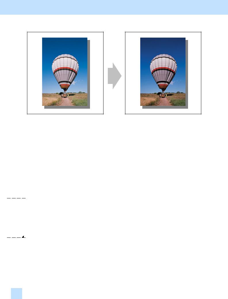
The output image looks light and blurred. |
The output image looks darker and sharper. |
Explanation
When an original containing photo images or gradational images is printed, the output image sometimes looks light and blurred. Perform image quality control or automatic calibration, and adjust the transfer roller bias output, in order to obtain a darker and sharper image.
Procedures
*Perform the adjustment in accordance with the procedures below.
*Procedures (1), (3) and (4) are used by the service technician only.
*Procedure (2) is used by the service technician, and by the user.


 (1) Enter adjustment mode [05]. Select code [395]. Press the [START] button.
• Image quality control will be forcibly performed to correct variations in density.
After exercising image quality control, print and check the image quality.
If further image quality adjustments are still necessary, use the next procedure.


 (2) Perform the automatic calibration to correct variations in image density.
*[ADMIN] is selected from among the [CALIBRATION DISPLAY LEVEL] options by default. In other words, an administrator is authorized to operate the automatic calibration. But the [USER] option can also be selected to allow the user to operate it. Refer to the User Functions Guide for further information regarding how to select the [CALIBRATION DISPLAY LEVEL] option.
1.1 e-STUDIO281c/351c/451c
1. General Adjustments – Copying, Printing and e-Filing (Output from Box)
To adjust the copy image quality
Use steps (a) through (i) to perform the automatic calibration.
(a)Press the [USER FUNCTIONS] button on the Control Panel to enter the "User Functions" menu.
(b)Press the [ADMIN] button.
(c)Enter the 6-digit administrator password. Press the [ENTER] button.
(d)Press the [GENERAL] button.
(e)Press the [CALIBRATION] button.
(f)Press the [COPY] button.
(g)Press the [CALIBRATION] button to print out the test chart.
(h)Place the printed test chart on the original glass.
(i)Press the [START] button to perform calibration. When the calibration comes to an end, the message "Scanning and calibrating" will disappear.
*As a result of the above steps, both the full-color and black-and-white copy image quality will be corrected simultaneously.
To adjust the print image quality
Use steps (a) through (k) to perform the automatic calibration.
(a)Press the [USER FUNCTIONS] button on the Control Panel to enter the "User Functions" menu.
(b)Press the [ADMIN] button.
(c)Enter the 6-digit administrator password. Press the [ENTER] button.
(d)Press the [GENERAL] button.
(e)Press the [CALIBRATION] button.
(f)Press the [PRINT] button.
(g)Press the desired resolution button ([600 x 600] or [1200 x 600]) of the PDL ("PS3" or "PCL" emulation), which will be based on the calibration.
(h)Press the [CALIBRATION] button to print out the test chart.
(i)Place the printed test chart on the original glass.
(j)Press the [START] button to perform calibration. When the calibration comes to an end, the message "Scanning and calibrating" will disappear.
(k)The message "Is a result made to reflect?" will appear. Press the [YES] button.
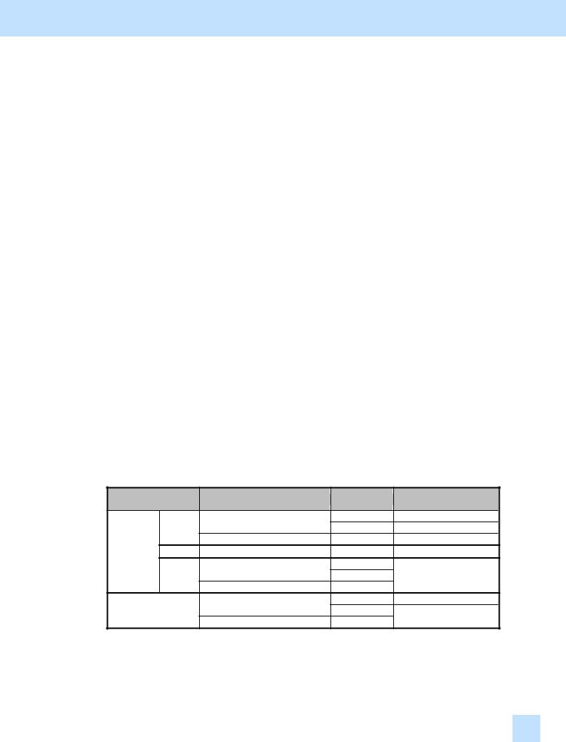
* Automatic calibration correction will be applied to printing performed under the following conditions:
Automatic calibration correction
Applied
Applied Not applied
Not applied
Applied
Applied
Not applied
Applied
Applied
Not applied
*The [1200 x 600] button will be displayed, provided that the optional GC-1181 and GC-1230 expansion memories are installed.
*Repeat the above steps to correct the resolution of the PDL ("PS3" or "PCL" emulation), if necessary.
After performing the automatic calibration, print and check the image quality.
If further image quality adjustments are still necessary, use the next procedure.
e-STUDIO281c/351c/451c 1.1

1. General Adjustments – Copying, Printing and e-Filing (Output from Box)


 (3) Enter adjustment mode [05]. Change the values for codes [234/236/237/238/239] to adjust the transfer (2nd transfer) roller bias output.
(Adjust the offset voltage of transfer roller bias so as to increase the density of the image.)
•The code to use varies, according to a type of paper used. Adjust the value for the [05] code corresponding to the paper type for which you would like to improve the image quality. Set the value within a range of "2" to "8" to obtain the highest density of the image.
|
|
Paper type |
|
|
[05] code |
|
|
Subcode |
|
Value |
Acceptable |
|
|
Default |
|
|
|
|
|
|
|
|
|
recommended |
value range |
|
|
|
|||||
|
|
|
|
|
|
|
|
|
|
|
|
|
|
|
||
|
|
Black |
|
Front |
|
|
|
0 |
|
|
|
|
|
|
|
|
|
Plain |
|
Back |
05-234 |
|
1 |
|
2 to 8 |
0 to 10 |
5 |
|
|||||
|
|
|
|
|
|
|||||||||||
|
paper |
Full color |
|
Front |
|
2 |
|
|
||||||||
|
|
|
|
|
|
|
|
|
|
|
|
|||||
|
|
|
Back |
|
|
|
3 |
|
|
|
|
|
|
|
||
|
|
|
|
|
|
|
|
|
|
|
|
|
|
|||
|
|
Black |
|
Front |
|
|
|
0 |
|
|
|
|
|
|
|
|
|
Thick 1 |
|
Back |
05-236 |
|
1 |
|
2 to 8 |
0 to 10 |
|
5 |
|
||||
|
|
|
|
|
|
|
||||||||||
|
Full color |
|
Front |
|
2 |
|
|
|
||||||||
|
|
|
|
|
|
|
|
|
|
|
|
|
||||
|
|
|
Back |
|
|
|
3 |
|
|
|
|
|
|
|
||
|
|
|
|
|
|
|
|
|
|
|
|
|
|
|||
|
Thick 2 |
Black |
|
05-237 |
|
0 |
|
2 to 8 |
0 to 10 |
5 |
|
|||||
|
Full color |
|
1 |
|
|
|||||||||||
|
|
|
|
|
|
|
|
|
|
|
|
|||||
|
Thick 3 |
Black |
|
05-238 |
|
0 |
|
2 to 8 |
0 to 10 |
|
5 |
|
||||
|
Full color |
|
1 |
|
|
|
||||||||||
|
|
|
|
|
|
|
|
|
|
|
|
|||||
|
OHP |
Black |
|
05-239 |
|
0 |
|
2 to 8 |
0 to 10 |
|
5 |
|
||||
|
Full color |
|
1 |
|
|
|
||||||||||
|
|
|
|
|
|
|
|
|
|
|
|
|||||
*"Front" refers to the printed side in simplex mode or the side that is delivered facing upwards in duplex mode. "Back" refers to the printed side that is delivered facing downwards in duplex mode.
*The table below shows you the acceptable paper weight for the paper types.
Paper type |
Acceptable paper weight |
|
Plain paper |
64 to 80 g/m² |
17 to 20 lb. Bond |
Thick 1 |
81 to 105 g/m² |
Max. 28 lb. Bond |
Thick 2 |
106 to 163 g/m² |
Max. 43 lb. Bond / 90 lb. Index |
Thick 3 |
164 to 209 g/m² |
Max. 55 lb. Bond / 110 lb. Index |
•After adjusting the transfer roller bias output, perform the automatic calibration in the same manner as in procedure (2).
<Hint> The transfer voltage increases as the set value is increased. It is usually recommended that the set value be increased, when printing on thick paper or paper with asperities on its surface. On the other hand, the set value should be decreased, when printing on thin paper.
After adjusting the density, print and check the image quality.
If further image quality adjustments are still necessary, use the next procedure.
1.1 e-STUDIO281c/351c/451c
1. General Adjustments – Copying, Printing and e-Filing (Output from Box)


 (4) Check the life of the consumables (particularly the drum, developer material and fuser unit) and replace them, if necessary.
•When replacing any consumable, use steps (a) to (c) below.
(a)Enter PM support mode. Reset the counter corresponding to the replaced consumable to "0."
*For further information regarding PM support mode, refer to the Service Handbook.
(b)Enter adjustment mode [05]. Select code [396]. Press the [START] button.
• Image quality control will be performed and the image quality control value will be initialized.
(c)Perform the automatic calibration in the same manner as in procedure (2).
*After replacing any consumable, remember to reset the counter corresponding to it to "0." Otherwise, it may cause a loss in copier performance, including degradation in the image quality and reduction in the life of the consumables.
*While replacing any consumable, also check the slit glass in the laser optical unit, and thoroughly clean it, if it is soiled.
Cautions after the completion of the adjustment
Nothing in particular.
Remarks
•Enter the value mentioned in the procedures or one within the recommended value range for the adjustment. Otherwise, it may cause a loss in copier performance, including degradation in the image quality and reduction in the life of the consumables.
•If printing on another type of paper causes a problem with the image quality after the adjustment, return the set values (for 05-234 to 239) to the default (set value: 5) and then perform the adjustment again.
•When replacing any consumable, refer to the relevant information in the Service Manual and Service Handbook.
e-STUDIO281c/351c/451c 1.1
1. General Adjustments – Copying, Printing and e-Filing (Output from Box)
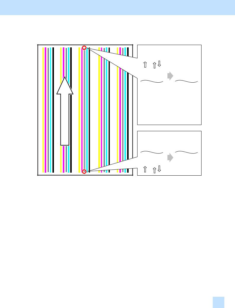
1.2 To Achieve the Image Quality Most Suitable for Paper Used
Before the adjustment
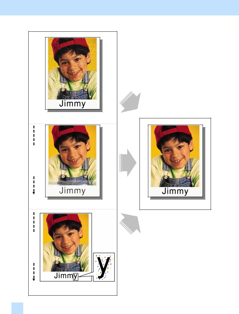
The image looks grained, depending on the type of paper.
Printing direction
The image quality at the trailing edge of the paper may become lighter, depending on the type of paper used.
Printing direction
After the adjustment
The clear image quality, most suitable for a type of paper used, is obtained.
Toner is splattered in the image, depending on the type of paper, used.
1.2 e-STUDIO281c/351c/451c

1. General Adjustments – Copying, Printing and e-Filing (Output from Box)
Explanation
The image sometimes looks slightly blurred or grained on the copy or printout, depending on the type of paper used. In addition, it may become lighter at the trailing edge of the paper. Adjust the transfer roller bias output, in order to achieve the image quality most suitable for the paper used.
Procedures
*The service technician must perform the adjustment in accordance with the procedures below.
*The procedure to use varies, depending on whether the image looks blurred/grained or becomes lighter at the trailing edge of the paper. Use the procedures, according to the image quality problem you have.
e-STUDIO281c/351c/451c 1.2

1. General Adjustments – Copying, Printing and e-Filing (Output from Box)
1.2.1 To Adjust the Blurred or Grained Image


 (1) Enter adjustment mode [05]. Change the values for codes [234/236/237/238/239] to adjust the transfer (2nd transfer) roller bias output.
(Adjust the offset voltage of transfer roller bias so as to optimize the halftones.)
•The code to use varies, according to a type of paper used. Adjust the value for the [05] code corresponding to the paper type for which you would like to improve the image quality. Set the value within a range of "2" to "8" to optimize the halftones.
|
|
Paper type |
|
|
[05] code |
|
|
Subcode |
|
Value |
Acceptable |
|
|
Default |
|
|
|
|
|
|
|
|
|
recommended |
value range |
|
|
|
|||||
|
|
|
|
|
|
|
|
|
|
|
|
|
|
|
||
|
|
Black |
|
Front |
|
|
|
0 |
|
|
|
|
|
|
|
|
|
Plain |
|
Back |
05-234 |
|
1 |
|
2 to 8 |
0 to 10 |
5 |
|
|||||
|
|
|
|
|
|
|||||||||||
|
paper |
Full color |
|
Front |
|
2 |
|
|
||||||||
|
|
|
|
|
|
|
|
|
|
|
|
|||||
|
|
|
Back |
|
|
|
3 |
|
|
|
|
|
|
|
||
|
|
|
|
|
|
|
|
|
|
|
|
|
|
|||
|
|
Black |
|
Front |
|
|
|
0 |
|
|
|
|
|
|
|
|
|
Thick 1 |
|
Back |
05-236 |
|
1 |
|
2 to 8 |
0 to 10 |
|
5 |
|
||||
|
|
|
|
|
|
|
||||||||||
|
Full color |
|
Front |
|
2 |
|
|
|
||||||||
|
|
|
|
|
|
|
|
|
|
|
|
|
||||
|
|
|
Back |
|
|
|
3 |
|
|
|
|
|
|
|
||
|
|
|
|
|
|
|
|
|
|
|
|
|
|
|||
|
Thick 2 |
Black |
|
05-237 |
|
0 |
|
2 to 8 |
0 to 10 |
|
5 |
|
||||
|
Full color |
|
1 |
|
|
|
||||||||||
|
|
|
|
|
|
|
|
|
|
|
|
|||||
|
Thick 3 |
Black |
|
05-238 |
|
0 |
|
2 to 8 |
0 to 10 |
5 |
|
|||||
|
Full color |
|
1 |
|
|
|||||||||||
|
|
|
|
|
|
|
|
|
|
|
|
|||||
|
OHP |
Black |
|
05-239 |
|
0 |
|
2 to 8 |
0 to 10 |
|
5 |
|
||||
|
Full color |
|
1 |
|
|
|
||||||||||
|
|
|
|
|
|
|
|
|
|
|
|
|||||
*"Front" refers to the printed side in simplex mode or the side that is delivered facing upwards in duplex mode. "Back" refers to the printed side that is delivered facing downwards in duplex mode.
*The table below shows you the acceptable paper weight for the paper types.
Paper type |
Acceptable paper weight |
|
Plain paper |
64 to 80 g/m² |
17 to 20 lb. Bond |
Thick 1 |
81 to 105 g/m² |
Max. 28 lb. Bond |
Thick 2 |
106 to 163 g/m² |
Max. 43 lb. Bond / 90 lb. Index |
Thick 3 |
164 to 209 g/m² |
Max. 55 lb. Bond / 110 lb. Index |
•After adjusting the transfer roller bias output, perform the automatic calibration.
*For further information regarding the procedures, refer to procedure (2) in 1.1 To Obtain a Darker Image.
<Hint> The transfer voltage increases as the set value is increased. It is usually desirable that the set value be decreased to obtain a clearly highlighted area.
After performing the adjustment, print and check the image quality.
If further image quality adjustments are still necessary, use the next procedure.
1.2 e-STUDIO281c/351c/451c

1. General Adjustments – Copying, Printing and e-Filing (Output from Box)


 (2) Check the life of the consumables (particularly the drum, developer material and fuser unit) and replace them, if necessary.
•When replacing any consumable, use steps (a) to (c) below.
(a)Enter PM support mode. Reset the counter corresponding to the replaced consumable part to "0."
*For further information regarding PM support mode, refer to the Service Handbook.
(b)Enter adjustment mode [05]. Select code [396]. Press the [START] button.
• Image quality control will be performed and the image quality control value will be initialized.
(c)Perform the automatic calibration.
*For further information regarding the procedures, refer to procedure (2) in 1.1 To Obtain a Darker Image.
*After replacing any consumable, remember to reset the counter corresponding to it to "0." Otherwise, it may cause a loss in copier performance, including degradation in the image quality and reduction in the life of the consumables.
*While replacing any consumable, also check the slit glass in the laser optical unit, and thoroughly clean it, if it is soiled.
Cautions after the completion of the adjustment
Nothing in particular.
Remarks
•Enter the value mentioned in the procedures or one within the recommended value range for the adjustment. Otherwise, it may cause a loss in copier performance, including degradation in the image quality and reduction in the life of the consumables.
•The desired image quality may not be obtained, depending on the type of paper used. In this case, use the recommended paper and then print or adjust the image quality.
•If printing on another type of paper causes a problem with the image quality after the adjustment, return the set values (for 05-234 to 239) to the default (set value: 5) and then perform the adjustment again.
•The adjustment will make up for the gap in the image quality and density between the front and back of the paper in duplex copying/printing. Particularly, if the image on the back is lighter than on the front, the image quality may be improved by increasing the set value for the transfer roller bias output.
•When replacing any consumable, refer to the relevant information in the Service Manual and Service Handbook.
e-STUDIO281c/351c/451c 1.2
1. General Adjustments – Copying, Printing and e-Filing (Output from Box)
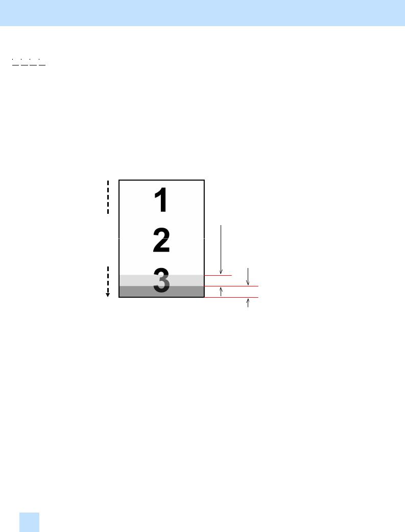
1.2.2 To Adjust the Light Image at the Trailing Edge/Splattering of Toner


 (1) Enter adjustment mode [05]. Change the value for code [293] or [1822] to adjust the transfer roller bias output at the trailing edge of the paper. (Adjust the ratio (%) of the transfer roller bias output at the center to the trailing edge of the paper, in order to ensure a uniform density between them.)
•The code to use varies, according to a type of paper used. Adjust the value for the [05] code corresponding to the paper type for which you would like to improve the image quality. Set the value within the recommended value range, in order to ensure a uniform density between the center and trailing edge of the paper.
•Use steps (a) to (b) to adjust the transfer roller bias output.
*The adjustment ranges of the transfer roller bias output at the trailing edge of the paper are as illustrated below.
Printing direction
Adjustment range B (05-1822)
Adjustment range A (05-293)
(a)Enter adjustment mode [05]. Change the value for code [293] to correct the transfer roller bias output at the trailing edge of the paper in adjustment range A.
|
Paper type |
|
|
[05] code |
|
|
Subcode |
|
Value |
Acceptable |
|
Default |
|
|
|
|
|
|
|
recommended |
value range |
|
|
||||
|
|
|
|
|
|
|
|
|
|
|
|
||
|
Plain paper |
|
|
|
0 |
|
|
|
85 |
|
|||
|
Thick 1 |
05-293 |
|
1 |
|
60 to 85 |
0 to 100 |
75 |
|
||||
|
Thick 2 |
|
2 |
|
80 |
|
|||||||
|
Thick 3 |
|
|
|
3 |
|
|
|
80 |
|
|||
|
OHP |
|
|
|
4 |
|
|
|
80 |
|
|||
1.2 e-STUDIO281c/351c/451c

1. General Adjustments – Copying, Printing and e-Filing (Output from Box)
(b)Enter adjustment mode [05]. Change the value for code [1822] to correct the transfer roller bias output in adjustment range B. (Specify an average factor, in order to prevent the transfer roller bias output from being rapidly changed between the center and trailing edge of the paper.)
|
Paper type |
|
|
[05] code |
|
|
Subcode |
|
Value |
Acceptable |
|
Default |
|
|
|
|
|
|
|
recommended |
value range |
|
|
||||
|
|
|
|
|
|
|
|
|
|
|
|
||
|
Plain paper |
|
|
|
0 |
|
|
|
|
|
|
||
|
Thick 1 |
05-1822 |
|
1 |
|
75 to 100 |
0 to 100 |
92 |
|
||||
|
Thick 2 |
|
2 |
|
|
||||||||
|
Thick 3 |
|
|
|
3 |
|
|
|
|
|
|
||
|
OHP |
|
|
|
4 |
|
|
|
|
|
|
||
*The value for code 05-1822 must be larger than the one for code 05-293, if the same subcodes are used. Example: Value for subcode 0 of 05-1822 ≥ Value for subcode 0 of 05-293
*The table below shows you the acceptable paper weight for the paper types.
Paper type |
Acceptable paper weight |
|
Plain paper |
64 to 80 g/m² |
17 to 20 lb. Bond |
Thick 1 |
81 to 105 g/m² |
Max. 28 lb. Bond |
Thick 2 |
106 to 163 g/m² |
Max. 43 lb. Bond / 90 lb. Index |
Thick 3 |
164 to 209 g/m² |
Max. 55 lb. Bond / 110 lb. Index |
<Hint> As the set value is decreased, the transfer voltage at the trailing edge of the paper becomes low and eventually the image quality will vary. (If the transfer voltage is too high relative to the paper weight, a transfer void will occur. (The density will be decreased.) To avoid this problem, decrease the transfer voltage.)
After performing the adjustment, print and check the image quality.
If further image quality adjustments are still necessary, use the next procedure.
e-STUDIO281c/351c/451c 1.2

1. General Adjustments – Copying, Printing and e-Filing (Output from Box)


 (2) Enter adjustment mode [05]. Change the value for code [434] to adjust the bottom margin.
*This adjustment will have an effect only on the image printed on the back of the paper (printed side delivered facing downwards) in duplex copying. Remember that it will not affect the image printed in simplex copying, the one printed on the front of the paper (printed side delivered facing upwards) in duplex copying, and the print image quality.
*In duplex copying, the bottom margin on the back of the paper may be narrower than on the front in simplex or duplex copying, depending on the paper size and how much paper is moistened. This results in the faint image at the trailing edge on the back of the paper. Adjust the bottom margin, in order to clearly copy at the trailing edge on the back of the paper.
•Use steps (a) to (b) to adjust the bottom margin.
(a)With the platen cover or RADF opened, make a double-sided copy. (Copy a solid black image.)
• Checking the copy image, determine how much the bottom margin should be increased.
*Select the best paper size for duplex copying, if necessary. It is recommended to use the paper, which is most frequently used for duplex copying.
*When making a double-sided copy of the solid black image, place blank paper on the original glass, allowing the solid black image to be copied only at the trailing edge on the back of the paper, for toner saving purposes.
(b)Enter adjustment mode [05]. Change the value for subcode "0" of code [434] to adjust the bottom margin on the back of the paper.
•The amount of change per step varies, depending on the paper size.
•Long size (A3/B4/LD/LG): The bottom margin will be increased by 0.042 mm per step.
•Short size (A4/LT): The bottom margin will be increased by 0.028 mm per step.
•Middle size (A4-R/LT-R, etc.): The bottom margin determined for the short size will be applied.
|
[05] code |
|
|
Subcode |
|
|
Value recommended |
|
Acceptable |
|
Default |
|
|
|
|
|
|
|
value range |
|
|
||||
|
|
|
|
|
|
|
|
|
|
|
|
|
|
|
|
|
|
|
|
Set a value larger than the current |
|
|
UC: 28 |
||
05-434 |
|
0 |
|
|
0 to 255 |
|
EUR: 45 |
|||||
|
|
|
one to increase the bottom margin. |
|
||||||||
|
|
|
|
|
|
|
|
|
Others: 45 |
|||
|
|
|
|
|
|
|
|
|
|
|
||
*Set the value in increments of approximately 12, while checking the copy image until the optimum value is obtained.
*Set "0" for the subcode. Setting "1" for the subcode allows you to adjust the right margin on the back in duplex copying, but it is not necessary here. Therefore, never change the value for subcode 1.
•After the adjustment, make a double-sided copy again, with the platen cover or RADF opened and check the image at the trailing edge on the back of the paper. If further image quality adjustments are still necessary, repeat step (b).
<Hint> If the user is concerned regarding the image quality at the trailing edge on the back of the paper, set a slightly wider bottom margin (3 to 4 mm). If not, it is recommended to set it to 2 to 3 mm.
1.2 e-STUDIO281c/351c/451c

1.General Adjustments – Copying, Printing and e-Filing (Output from Box)
Cautions after the completion of the adjustment
Too small a set value may possibly cause the image to become light, if a darker image is laid out at the trailing edge of the original. Therefore, carefully perform the adjustment, while checking the copy image.
Remarks
•Enter the value mentioned in the procedures or one within the recommended value range for the adjustment. Otherwise, it may cause a loss in copier performance, including degradation in the image quality and reduction in the life of the consumables.
•The desired image quality may not be obtained, depending on the type of paper used. In this case, use the recommended paper and then print or adjust the image quality.
•If printing on another type of paper causes a problem with the image quality after the adjustment, return the set values (for codes 05-239 and 1822) to the defaults and then perform the adjustment again.
•The adjustment will make up for the gap in the image quality and density at the trailing edge between the front and back of the paper in duplex copying. Particularly, if the image at the trailing edge on the back of the paper is light, the image quality may be improved by decreasing the set value for the transfer roller bias output.
e-STUDIO281c/351c/451c 1.2
1. General Adjustments – Copying, Printing and e-Filing (Output from Box)
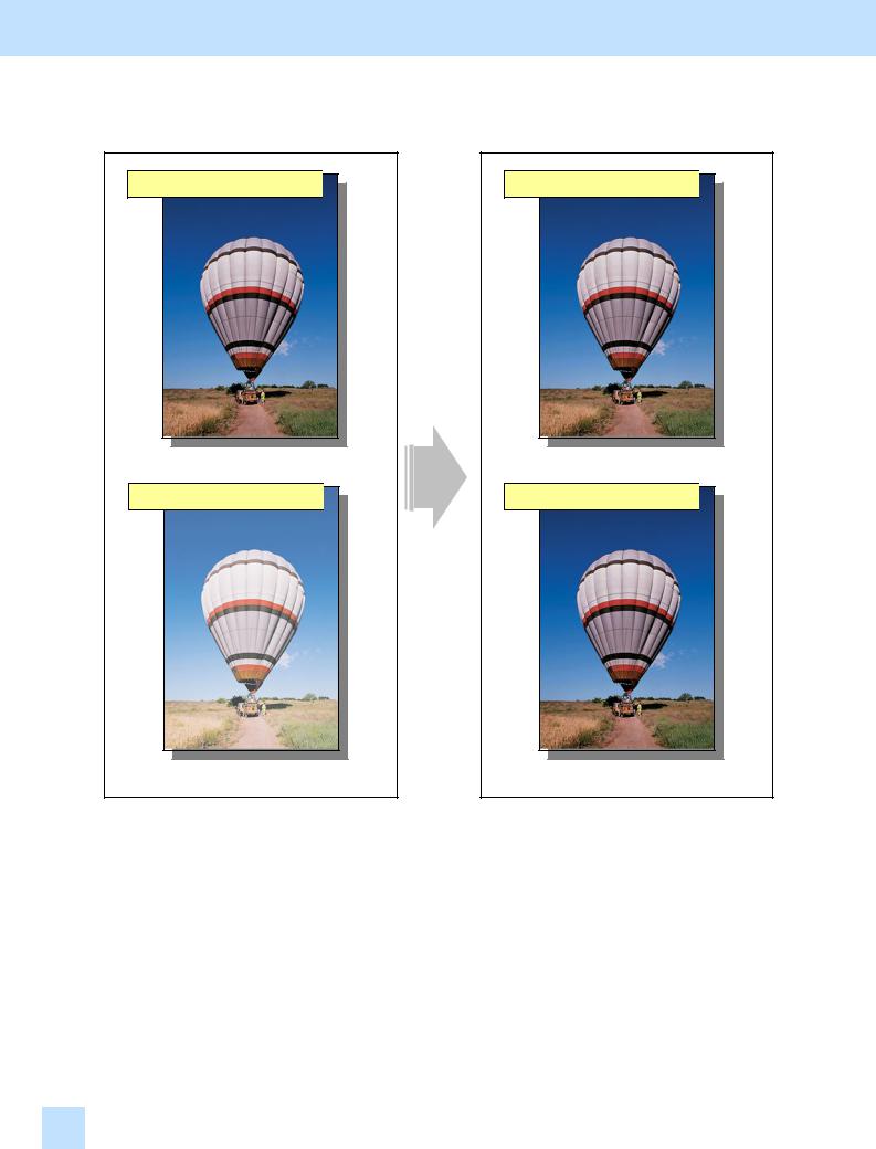
1.3 To Minimize Variations in the Image Quality after Power-on
(To optimally program image quality control)
Before the adjustment
Immediately after power-on 
Immediately after power-on 
The image quality varies, depending on the operating environment or condition at power-on.
Explanation
After the adjustment
Immediately after power-on 
Immediately after power-on 
The uniform image quality is ensured, every time the copier is turned on.
If copying or printing is performed immediately after the copier is turned on or when it is returned from energy saving mode, there will be variations in the density of the image. (It will not occur when the copier is temporarily turned off and on for releasing jammed paper or when it is shortly returned from energy saving mode.) Switch the image quality control mode to the mode, which gives a higher priority to accuracy in image quality control, in order to ensure the uniform image quality, every time the copier is turned on.
*Image quality control is performed in mode 1 by default, which is intended to reduce the warm-up time. Switch it to mode 2, which is intended to increase the interval during which image quality control is performed.
1.3e-STUDIO281c/351c/451c
1. General Adjustments – Copying, Printing and e-Filing (Output from Box)
Procedures
*The service technician must perform the adjustment in accordance with the procedures below.


 (1) Enter setting mode [08]. Change the value for code [559] to "2" to place image quality control in mode 2. It is intended to increase the interval during which image quality control is performed.
Value for 08-559 |
Image quality control immediately after the copier is turned on |
0 |
Invalid |
1 |
Valid: Mode 1 (default) |
2 |
Valid: Mode 2 |
• After switching to mode 2, forcibly perform image quality control, as follows: Enter adjustment mode [05]. Select code [395]. Press the [START] button.
After forcibly exercising image quality control, print and check the image quality.
If further image quality adjustments are still necessary, use the next procedure.


 (2) Check the life of the consumables (particularly the drum, developer material and transfer belt unit) and replace them, if necessary.
•When replacing any consumable, use steps (a) to (c) below.
(a)Enter PM support mode. Reset the counter corresponding to the replaced consumable to "0."
*For further information regarding PM support mode, refer to the Service Handbook.
(b)Enter adjustment mode [05]. Select code [396]. Press the [START] button.
• Image quality control will be performed and the image quality control value will be initialized.
(c)Perform the automatic calibration.
*For further information regarding the procedures, refer to procedure (2) in 1.1 To Obtain a Darker Image.
*After replacing any consumable, remember to reset the counter corresponding to it to "0." Otherwise, it may cause a loss in copier performance, including degradation in the image quality and reduction in the life of the consumables.
*While replacing any consumable, also check the slit glass in the laser optical unit, and thoroughly clean it, if it is soiled.
Cautions after the completion of the adjustment
Switching image quality control mode will increase the warm-up time by approximately 25 seconds at maximum, immediately after the copier is turned on or returned from energy saving mode. In addition, it will increase the interval during which image quality control is performed. This may possibly shorten the life of the consumables. Pay special attention to these factors and perform the adjustment, while checking the image quality.
Remarks
When replacing any consumable, refer to the relevant information in the Service Manual and Service Handbook.
e-STUDIO281c/351c/451c 1.3
1. General Adjustments – Copying, Printing and e-Filing (Output from Box)
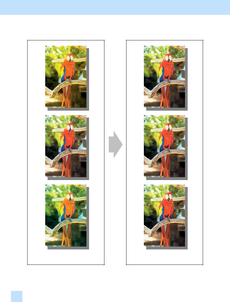
1.4 To Minimize Variations in the Image Quality under the Operating Conditions
(To optimally program image quality control)
Before the adjustment |
|
|
|
After the adjustment |
||||
|
|
|
|
|
|
|
|
|
|
|
|
|
|
|
|
|
|
|
|
|
|
|
|
|
|
|
|
|
|
|
|
|
|
|
|
|
|
|
|
|
|
|
|
|
|
|
|
|
|
|
|
|
|
|
|
|
|
|
|
|
|
|
|
|
|
|
|
|
|
|
|
|
|
|
|
|
|
|
|
|
|
|
|
|
|
|
|
|
|
|
|
|
|
|
|
|
|
|
|
|
|
|
|
|
|
|
|
|
|
|
|
|
|
|
|
|
The image contrast varies, depending on the date and time when copying or printing is performed or the type of job.
The image quality is constantly maintained.
1.4 e-STUDIO281c/351c/451c

1. General Adjustments – Copying, Printing and e-Filing (Output from Box)
Explanation
The image contrast may vary, depending on the date and time when copying or printing is performed or the type of copy/print job. To constantly maintain image quality, shorten the waiting period until image quality control is performed.
Procedures
*The service technician must perform the adjustment in accordance with the procedures below.


 (1) Enter setting mode [08]. Change the value for code [570], [571] or [572] to specify the best interval during which image quality control is performed, according to use of the copier. In addition, change the value for code [565] or [566] to switch image quality control mode to mode 2. It gives a higher priority to accuracy in image quality control.
The copier is installed in a place where the temperature and humidity vary widely:
Use steps (a) to (b) and perform the adjustment of image quality control.
(a)Change the value for 08-405 within the range from "1" to "3" (value × %R.H.) to increase the frequency of image quality control, in response to a change in humidity.
*Image quality control will be performed, when the relative humidity changes in accordance with the specified difference from the previous image quality control. If the difference in the relative humidity exceeds the specified value, image quality control is performed, first. Then a copy or print
job will be performed.
Value for 08-570 |
Difference in relative humidity |
1 to 3 |
5%R.H. to 15%R.H. |
4 |
20%R.H. (default) |
(b)Change the value for code 08-565 to "2" to place image quality control in mode 2. It is intended to increase the interval during which image quality control is performed.
Value for 08-565 |
Image quality control when the relative humidity varies |
0 |
Invalid |
1 |
Valid: Mode 1 (default) |
2 |
Valid: Mode 2 |
• After switching to mode 2, forcibly perform image quality control, as follows: Enter adjustment mode [05]. Select code [395]. Press the [START] button.
e-STUDIO281c/351c/451c 1.4

1. General Adjustments – Copying, Printing and e-Filing (Output from Box)
A very small number of copies are output (approx. one copy per hour):
Use steps (a) to (b) and perform the adjustment of image quality control.
(a)Change the value for 08-571 within the range from "1" to "3" to reduce the waiting period until image quality control is performed.
*When a copy or print job is initiated, if the waiting period until image quality control is performed has already elapsed, image quality control is performed, first. Then a copy or print job will be performed.
Value for 08-571 |
Waiting period until image quality control is performed |
1 to 3 |
1 to 3 hours |
4 |
4 hours (default) |
(b)Change the value for code 08-566 to "2" to place image quality control in mode 2. It is intended to increase the interval during which image quality control is performed.
Value for 08-566 |
Image quality control when the specified waiting period has already elapsed |
0 |
Invalid |
1 |
Valid: Mode 1 (default) |
2 |
Valid: Mode 2 |
• After switching to mode 2, forcibly perform image quality control, as follows: Enter adjustment mode [05]. Select code [395]. Press the [START] button.
A large number of sheets are printed (hundreds of copies or more per day) and the image quality needs to be constantly maintained:
Change the value for code 08-572 to "1" to "9" (Value × 100 sheets) to reduce the accumulated number of sheets printed. It will determine the interval until the next image quality control is performed.
* After a copy or print job is completed, if the accumulated number of sheets printed exceeds the specified value, image quality control will be performed.
Value for 08-572 |
Accumulated number of sheets printed until image quality control is performed |
1 to 9 |
100 to 900 sheets |
10 |
1,000 sheets (default) |
*Use code 08-567 to define in which mode image quality control is performed, when the accumulated number of sheets printed exceeds the specified value. Mode 2 is selected by default. It is intended to increase the interval during which image quality control is performed and maintain the image quality
with high accuracy. Therefore, never change the value for this code, unless otherwise required.
|
Value for 08-567 |
|
Image quality control when the accumulated number of sheets |
|
|
printed exceeds the specified value |
|
|
|
|
|
0 |
|
Invalid |
|
1 |
|
Valid: Mode 1 |
|
2 |
|
Valid: Mode 2 (default) |
|
• After changing the value for code 08-572, forcibly perform image quality control, as follows: Enter adjustment mode [05]. Select code [395]. Press the [START] button.
After performing the adjustment, print and check the image quality.
If further image quality adjustments are still necessary, use the next procedure.
1.4 e-STUDIO281c/351c/451c

1. General Adjustments – Copying, Printing and e-Filing (Output from Box)


 (2) Check the life of the consumables (particularly the drum, developer material and transfer belt unit) and replace them, if necessary.
•When replacing any consumable, use steps (a) to (c) below.
(a)Enter PM support mode. Reset the counter corresponding to the replaced consumable to "0."
*For further information regarding PM support mode, refer to the Service Handbook.
(b)Enter adjustment mode [05]. Select code [396]. Press the [START] button.
• Image quality control will be performed and the image quality control value will be initialized.
(c)Perform the automatic calibration.
*For further information regarding the procedures, refer to procedure (2) in 1.1 To Obtain a Darker Image.
*After replacing any consumable, remember to reset the counter corresponding to it to "0." Otherwise, it may cause a loss in copier performance, including degradation in the image quality and reduction in the life of the consumables.
*While replacing any consumable, also check the slit glass in the laser optical unit, and thoroughly clean it, if it is soiled.
Cautions after the completion of the adjustment
•The adjustment may possibly slow down the copying or printing speed and shorten the life of the consumables. Therefore, carefully perform the adjustment, while checking the image.
•Switching image quality control mode will increase the interval of image quality control by approximately 25 seconds at maximum. It is performed before or after a copy or print job is performed. This may possibly cause loss in the life of consumables. Pay special attention to these factors and perform the adjustment, while checking the image quality.
Remarks
•Enter the value mentioned in the procedures or one within the recommended value range for the adjustment. Otherwise, it may cause a loss in copier performance, including slowdown in the copying or printing speed.
•When replacing any consumable, refer to the relevant information in the Service Manual and Service Handbook.
e-STUDIO281c/351c/451c 1.4
1. General Adjustments – Copying, Printing and e-Filing (Output from Box)
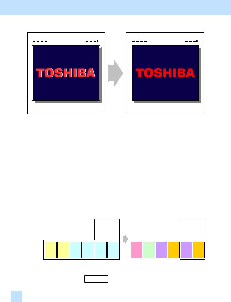
1.5 To Correct Out-of-Register Colors
Before the adjustment
Paper feeding direction
After the adjustment
Paper feeding direction
The text and background are misaligned or out of register.
Text is aligned with the background and a clear copy/print image is obtained.
Explanation
Colors of text or a thin line are sometimes printed out of register. Perform color registration control, in order to print or copy without out-of-register colors.
*The e-STUDIO281c/351c/451c provides more accurate color registration control than the e-STUDIO3511/4511 (conventional models).
e-STUDIO3511/4511: |
Only A3/LD-sized paper can be corrected (a and b as illustrated below). The |
||||||||||||||||
|
|
|
|
|
value set for A3/LD-sized paper will be automatically applied to the A4/LT- |
||||||||||||
|
|
|
|
|
sized paper. |
|
|
|
|
|
|
|
|
|
|
||
e-STUDIO281c/351c/451c: |
A3/LD-sized paper (A and B as illustrated below) and A4/LT-sized paper (C to |
||||||||||||||||
|
|
|
|
|
F as illusted below) can be individually corrected. |
|
|
|
|
||||||||
|
|
e-STUDIO3511/4511 |
|
|
|
e-STUDIO281c/351c/451c |
|
||||||||||
|
1 page |
2 |
|
|
3 |
|
|
1 page |
2 |
|
|
3 |
|||||
|
|
|
|
|
|
|
|
|
|
|
|
|
|
|
|
|
|
A3/LD |
a |
|
|
|
b |
|
|
b |
|
|
A |
|
|
B |
|
|
B |
|
|
|
|
|
|
|
|
|
|
|
|
|
|
|
|
|
|
|
|
|
|
|
|
|
|
|
|
|
|
|
|
|
|
|
|
A4/LT |
|
a |
|
|
|
a |
|
|
|
b |
|
|
|
b |
|
|
|
b |
|
|
|
b |
|
|
|
C |
|
|
|
D |
|
|
|
E |
|
|
|
F |
|
|
|
E |
|
|
|
F |
|
|
|
|
|
|
|
|
|
|
|
|
|
|
|
|
|
|
|
|
|
|
|
|
|
|
|
|
|
|
|
|
|
|
|
|
|
|
|
|
|
|
|
|
|
|
|
|
|
|
1 page |
2 |
|
3 |
|
4 |
|
5 |
|
6 |
|
|
1 page |
2 |
|
3 |
|
4 |
|
5 |
|
6 |
|
||||||||||||||||||||||||
: Pages where the value is automatically applied
1.5 e-STUDIO281c/351c/451c

1. General Adjustments – Copying, Printing and e-Filing (Output from Box)
Procedure
*The service technician must perform the adjustment in accordance with the procedure below.
(1)Make sure that no out-of-register colors are recognized on an original.
(2)Check a direction in which colors are misaligned.
*This adjustment is intended to correct the print start timing of the toner colors in the secondary scanning direction, in order to align the print positions of 3 toner colors (K, C and Y) with magenta (M). Therefore, it will be effective, only if colors are misaligned in the paper feeding direction (or the secondary scanning direction). If colors are misaligned in the direction perpendicular to the paper feeding direction (or the primary scanning direction), refer to <Hint> below.
<Hint> If colors are misaligned in the direction perpendicular to the paper feeding direction, enter test mode [03] and rotate the transfer belt for 5 minutes. (The main motor drives the transfer belt. Use 03-101 to rotate the main motor or 03-151 to stop it.) After that, check the copy or print image. If the colors still misaligned, replace the transfer belt or transfer belt unit. For further information regarding how to use test mode [03] and transfer belt replacement procedures, refer to the Service Manual and Service Handbook.
(3)Correct out-of-register colors in the secondary scanning direction.
*Two types of the color registration control procedures are provided (one type for A4/LT-sized paper), and the test print pattern varies according to the procedures. Either of the patterns is available to correct out- of-register colors. Therefore, print out whichever one is easier to use.
|
Procedure |
|
|
[05] code |
|
|
Test print pattern |
|
Printing |
Paper |
No. of copies |
Referred |
|
|
|
|
|
|
image |
size |
to be printed |
to |
|||
|
|
|
|
|
|
|
|
|
||||
|
Procedure 1 |
05-63 |
|
|
Test print pattern 63 |
Ladder |
A3/LD |
2 |
1.5.1 |
|||
|
05-68 |
|
|
Test print pattern 68 |
A4/LT |
4 |
1.5.2 |
|||||
|
|
|
|
|
|
|||||||
|
Procedure 2 |
05-64 |
|
|
Test print pattern 64 |
Block |
A3/LD |
2 |
1.5.3 |
|||
*Use steps in order, as listed below. If you start with other than step "1," use subsequent steps to the primary one. (e.g. If you start with step "2," subsequently use steps "3," "4," "5" and "6" in order.)
|
Order |
|
|
[05] code |
|
|
Procedure |
|
Paper and range to be |
|
Remarks* |
|
|
|
|
|
|
|
corrected |
|
|
||||
|
|
|
|
|
|
|
|
|
|
|
|
|
1 |
|
05-417 |
|
|
Procedure 1 or 2 |
A3/LD, 1st page |
|
A |
||||
2 |
|
05-418 |
|
|
A3/LD, 2nd page |
|
B |
|||||
|
|
|
|
|
|
|||||||
3 |
|
05-953 |
|
|
|
|
A4/LT, 1st page |
|
C |
|||
4 |
|
05-954 |
|
|
Procedure 1 |
A4/LT, 2nd page |
|
D |
||||
5 |
|
05-955 |
|
|
A4/LT, 3rd page |
|
E |
|||||
|
|
|
|
|
|
|||||||
6 |
|
05-956 |
|
|
|
|
A4/LT, 4th page |
|
F |
|||
*The alphabet in Remarks in the table above indicates a page to be printed as illustrated in " Explanation" in the previous page.
<Hint> • First, change the values for codes 05-417 and 418 to "correct out-of-register colors on A3/LDsized paper" and "roughly correct out-of-register colors on A4/LT-sized paper." Next, change the values for codes 05-953 to 956 to "further correct out-of-register colors on A4/LT-sized paper."
•The values for codes 05-417 and 418 are applied, in order to print or copy an original, on which a page data is pasted, on the transfer belt. The values for codes 05-953 to 956 are applied, in order to print or copy an original, on which a two-page data is pasted, on transfer belt.
*Refer to the color registration control procedures described later for further information regarding each procedure.
e-STUDIO281c/351c/451c 1.5

1. General Adjustments – Copying, Printing and e-Filing (Output from Box)
1.5.1Color Registration Control Procedure 1: To Correct Out-of-register colors on A3/LD-sized Paper with Test Print Pattern 63 (05-63)
(1)Enter adjustment mode [05] and print out the test print pattern to correct out-of-register colors.
• Use steps (a) to (b) to print out the test print pattern.
(a)Select A3/LD-sized paper.
(b)Enter a code corresponding to a desired test print pattern. Press the [FAX] button.
• Print out any of the following test print patterns in the table below.
|
[05] code |
|
|
Test print pattern |
|
Paper |
No. of copies |
|
|
|
|
size |
to be printed |
||
|
|
|
|
|
|
||
05-62 |
|
|
Grid pattern (for identifying out-of-register colors) |
A3/LD |
2 |
||
05-63 |
|
|
Test print pattern 63 (ladder pattern) |
A3/LD |
2 |
||
*Use code 05-62. The grid pattern will be printed on the entire copy, with all toner colors (C, M, Y and K) overlaid. Check the printed grid pattern (or whether the toner colors are accurately overlaid) to discover out-of-register colors on the entire copy.
*Jot down a "page number" and "paper feeding direction" on the printed test print pattern beforehand. This facilitates identifying out-of-register colors in the subsequent adjustment.


 (2) Enter adjustment mode [05]. Change the values for codes [417] and [418] to correct out-of-register colors.
•Align 3 toner colors (Y, C and K) with magenta (M). First, change the value for code 05-417 and correct out-of-register colors on the first page of the test print pattern. Next, print out the 2 copies of test print
pattern again. Change the value for code 05-418 and correct out-of-register colors on the second page.
Color |
[05] code |
Subcode |
Value recommended |
Acceptable value range |
|
Y (yellow) |
|
3 |
|
|
|
M (magenta) |
05-417 |
2 |
125 to 131 |
118 to 138 |
|
C (cyan) |
1 |
||||
|
|
|
|||
K (black) |
|
0 |
|
|
|
Y (yellow) |
|
3 |
|
|
|
M (magenta) |
05-418 |
2 |
125 to 131 |
118 to 138 |
|
C (cyan) |
1 |
||||
|
|
|
|||
K (black) |
|
0 |
|
|
*If the set value is increased by 1, the print position of the color will be shifted for 0.0423 mm toward the trailing edge of the paper. (For instance, if the value for code 05-417-1 is increased by 3, the print position of cyan will be shifted for 0.1269 mm (0.0423mm x 3) toward the trailing edge of the paper. This correction will affect all pages.
1.5 e-STUDIO281c/351c/451c
1. General Adjustments – Copying, Printing and e-Filing (Output from Box)
How to use test print pattern for correcting out-of-register colors (ladder pattern)
Align 3 toner colors (Y, C and K) with magenta (M) at the leading edge and trailing edge of the test print
pattern.
Paper feeding direction
Correction at the leading edge
|
|
|
|
Before |
|
|
|
|
|
|
After |
|
|||||||||
|
|
|
|
|
|
|
|
|
|
|
|
|
|
|
|
|
|
|
|
|
|
|
|
|
|
|
|
|
|
|
|
|
|
|
|
|
|
|
|
|
|
|
|
|
|
|
|
|
|
|
|
|
|
|
|
|
|
|
|
|
|
|
|
|
|
|
|
|
|
|
|
|
|
|
|
|
|
|
|
|
|
|
|
|
|
|
|
|
|
|
|
|
|
|
|
|
|
|
|
|
|
|
|
|
|
|
|
|
|
|
|
|
|
|
|
|
|
|
|
|
|
|
|
|
|
|
|
|
|
|
|
|
|
|
|
|
|
|
|
|
|
|
|
|
|
|
|
|
|
|
|
|
|
|
|
|
|
|
|
|
|
|
|
|
|
|
|
|
|
|
|
|
|
|
|
Align the print positions of Y, C and K to M. To correct out-of-register colors:
•Decrease the value for Y.
•Decrease the value for C.
•Increase the value for K.
Correction at the trailing edge
|
|
|
|
Before |
|
|
|
|
|
|
|
After |
|
|
||||||||
|
|
|
|
|
|
|
|
|
|
|
|
|
|
|
|
|
|
|
|
|
|
|
|
|
|
|
|
|
|
|
|
|
|
|
|
|
|
|
|
|
|
|
|
|
|
|
|
|
|
|
|
|
|
|
|
|
|
|
|
|
|
|
|
|
|
|
|
|
*If the colors cannot be aligned at the leading edge and trailing edge of the test print pattern, change the value to equalize the amount of out-of-register colors between the leading edge and trailing edge.
*If the direction or the amount of out-of-register colors is not consistent, print out several copies of the test print pattern to identify a pattern for the out-of-register colors (direction and amount). Then perform the adjustment most suitable for it.
e-STUDIO281c/351c/451c 1.5

1. General Adjustments – Copying, Printing and e-Filing (Output from Box)
1.5.2Color Registration Control Procedure 1: To Correct Out-of-register colors on A4/LT -sized Paper with Test Print Pattern 68 (05-68)
(1) Enter adjustment mode [05] and print out the test print pattern to correct out-of-register colors.
•Use steps (a) to (b) to print out the test print pattern.
(a)Select A4/LT-sized paper.
(b)Enter a code corresponding to a desired test print pattern. Press the [FAX] button.
• Print out any of the following test print patterns in the table below.
|
[05] code |
|
|
Test print pattern |
|
Paper |
No. of copies |
|
|
|
|
size |
to be printed |
||
|
|
|
|
|
|
||
05-69 |
|
|
Grid pattern (for identifying out-of-register colors) |
A4/LT |
4 |
||
05-68 |
|
|
Test print pattern 68 (ladder pattern) |
A4/LT |
4 |
||
*Use code 05-69. The grid pattern will be printed on the entire copy, with all toner colors (C, M, Y and K) overlaid. Check the printed grid pattern (or whether the toner colors are accurately overlaid) to discover out-of-register colors on the entire copy.
*Jot down a "page number" and "paper feeding direction" on the printed test print pattern beforehand. This facilitates identifying out-of-register colors in the subsequent adjustment.
*Refer to procedure (2) of "1.5.1 Color Registration Control Procedures 1: To Correct Out-of-register colors on A3/LD-sized Paper with Test Print Pattern 63 (05-63)" for further information regarding the test print pattern sample and adjustment procedures.


 (2) Enter adjustment mode [05]. Change the values for codes [953 to 956] to correct out-of-register colors.
•Align 3 toner colors (Y, C and K) with magenta (M). First, change the value for code 05-953 and correct out- of-register colors on the first page of the test print pattern. Next, print out the 4 copies of test print pattern again. Change the value for code 05-954 and correct out-of-register colors on the second page. Similarly, print out the 4 copies of test print pattern at each time of correction. Change the value for code 05-955 and correct out-of-register colors on the third page, and change the value for code 05-956 and correct out-of-
register colors on the fourth page.
Color |
[05] code |
Subcode |
Value recommended |
Acceptable value range |
|
Y (yellow) |
|
3 |
|
|
|
M (magenta) |
05-953 |
2 |
125 to 131 |
118 to 138 |
|
C (cyan) |
1 |
||||
|
|
|
|||
K (black) |
|
0 |
|
|
|
Y (yellow) |
|
3 |
|
|
|
M (magenta) |
05-954 |
2 |
125 to 131 |
118 to 138 |
|
C (cyan) |
1 |
||||
|
|
|
|||
K (black) |
|
0 |
|
|
|
Y (yellow) |
|
3 |
|
|
|
M (magenta) |
05-955 |
2 |
125 to 131 |
118 to 138 |
|
C (cyan) |
1 |
||||
|
|
|
|||
K (black) |
|
0 |
|
|
|
Y (yellow) |
|
3 |
|
|
|
M (magenta) |
05-956 |
2 |
125 to 131 |
118 to 138 |
|
C (cyan) |
1 |
||||
|
|
|
|||
K (black) |
|
0 |
|
|
*If the set value is increased by 1, the print position of the color will be shifted for 0.0423 mm toward the trailing edge of the paper. (For instance, if the value for code 05-953-1 is increased by 3, the print position of cyan will be shifted for 0.1269 mm (0.0423mm x 3) toward the trailing edge of the paper. This correction will affect all pages.
1.5e-STUDIO281c/351c/451c
Loading...