


Toro 73470, 73471, 73540, 73541, 73542 Service Manual
...5XI SERIES TRACTOR HYDRAULIC SYSTEMS SERVICE MANUAL
Table of Contents – Page 1 of 2
SAFETY INFORMATION
GENERAL INFORMATION
THINK SAFETY FIRST
SPECIFICATIONS
TRANSMISSION (EATON MODEL) TRANSAXLE (WHEEL HORSE)
5XI AUTOMATIC TRANSMISSION SYSTEM SPEEDS OIL
BOLT TORQUE
EPOXY PATCH SCREWS
SINGLE-USE FASTENERS CRITICAL FASTENERS
MAINTENANCE
SERVICE SCHEDULE TABLE
TRANSAXLE FLUID
GENERAL INFORMATION
CHECKING FLUID LEVEL
FLUID CHANGE
FILTER CHANGE
BRAKE
GENERAL INFORMATION
ADJUSTMENT
NEUTRAL ADJUSTMENT
GENERAL INFORMATION
ADJUSTMENT PROCEDURE
POWER STEERING
GENERAL INFORMATION
TROUBLESHOOTING THEORY OF OPERATION
GENERAL INFORMATION TRANSMISSION OPERATION
HYDROSTATIC TRANSMISSION FLOW DIAGRAM WITH POWER STEERING HYDROSTATIC TRANSMISSION FLOW DIAGRAM WITHOUT POWER STEERING POWER STEERING CYLINDER HYDRAULIC HOSE ROUTING
LIFT CYLINDER HYDRAULIC HOSE ROUTING
HYDROSTATIC TRANSMISSION FLOW DIAGRAM, UNITS WITHOUT POWER STEERING TROUBLESHOOTING TABLES
TRACTOR WILL NOT OPERATE IN EITHER DIRECTION; ENGINE BOGS DOWN OR STALLS
TRACTOR GOES FORWARD ONLY AT PARTIAL SPEED AND IS SLOW OR DOES NOT OPERATE IN REVERSE TRACTOR WILL NOT OPERATE IN EITHER DIRECTION
TRACTOR OPERATES ERRATICALLY
TRACTOR OPERATES IN BOTH DIRECTIONS BUT WITH LOSS OF POWER (WORSENS AS BECOMES HOT)
5XI SERIES TRACTOR HYDRAULIC SYSTEMS SERVICE MANUAL
Table of Contents – Page 2 of 2
TROUBLESHOOTING TABLES - Continued TRANSMISSION OVERHEATING ABNORMAL VIBRATION OR NOISE
HYDRAULIC LIFT SYSTEM DOES NOT OPERATE OR DOES NOT OPERATE PROPERLY OIL IS LEAKING OUT HIGH-LOW SHIFT FORK HOLE DURING OPERATION
TROUBLESHOOTING FLOW CHARTS
TRACTOR WILL NOT OPERATE IN EITHER DIRECTION
TRACTOR OPERATES, BUT LOSES POWER AS OIL BECOMES HOT AND/OR TRANSMISSION OVERHEATS TRACTOR DOES NOT RETURN TO NEUTRAL
TRACTOR OPERATES NORMALLY IN ONE DIRECTION, BUT IS VERY SLOW IN OPPOSITE DIRECTION TRACTOR OPERATES IN ONLY ONE DIRECTION
TRACTOR OPERATES ERRATICALLY
HYDRAULIC LIFT SYSTEM DOES NOT OPERATE, OR DOES NOT OPERATE PROPERLY HYDRAULIC SYSTEMS TESTING
TESTING SYSTEM PERFORMANCE PRESSURE CHECKS
LIFT SYSTEM PRESSURE CHARGE PRESSURE
REPAIR PROCEDURES
CHASSIS
REAR FENDERS, FOOTRESTS, & TUNNEL
GENERAL INFORMATION
TRANSAXLE R & R
REMOVAL
REASSEMBLY
SMART TURN™ LINKAGE ADJUSTMENTS
HYDROSTATIC DRIVE
TRANSMISSION/TRANSAXLE
DISASSEMBLY
DIFFERENTIAL DISASSEMBLY
REASSEMBLY
HYDROSTATIC TRANSMISSION
TRANSMISSION DISASSEMBLY
REASSEMBLY
HYDRAULIC SYSTEMS
LIFT CYLINDER R & R
LIFT CYLINDER DISASSEMBLY / REASSEMBLY
STEERING CYLINDER R & R
POWER STEERING CYLINDER DISASSEMBLY / REASSEMBLY
POWER STEERING VALVE R & R
POWER STEERING VALVE DISASSEMBLY / REASSEMBLY
STEERING VALVE DISASSEMBLY
REASSEMBLY
LIFT VALVE R & R

TORO®
5xi Series Tractor
Hydraulic Systems Service Manual

ABOUT THIS MANUAL
This service manual was written expressly for Toro Wheel Horse 5xi series garden tractors. The Toro Company has made every effort to make the information in this manual complete and correct.
This service and repair manual has been compiled to provide authorized Wheel Horse service personnel with the proper procedures and techniques for servicing the Wheel Horse automatic transaxle with Eaton Model 11 hydrostatic transmission. Basic mechanical/electrical skills are assumed. The Table of Contents lists the systems and the related topics covered in this manual.
It is advisable to read all the introductory sections first to gain a proper understanding of the Wheel Horse automatic transmission system.
For information on the electrical system, please refer to the Toro Electrical Demystification Guide (492-4404). For general service procedures, refer to the 5xi Series Tractor Service Manual (492-4715). For information specific to the engines used on these garden tractors, refer to the appropriate engine manufacturer’s service and repair instructions.
We are hopeful that you will find this manual a valuable addition to your service shop. If you have any questions or comments regarding this manual, please contact us at the following address:
The Toro Company
Consumer Service Training Department
8111 Lyndale Avenue South
Bloomington, MN 55420
The Toro Company reserves the right to change product specifications or this manual without notice.
The automatic transmission and transaxle are sophisticated pieces of machinery. Maintain strict cleanliness control during all stages of service and repair. Cover or cap all hose ends and fittings whenever they are exposed. Even a small amount of dirt or other contamination can severely damage the system.
NOTE: This manual uses the terms “transmission, hydrostatic transmission, and hydrostatic unit” to refer to the Eaton Model 11 Hydrostatic Transmission. The term “transaxle” is used to refer to the assembly of intermediate gears, differential and case halves, less hydrostatic unit. “Transmission System” and “Automatic Transmission System” are used to refer to entire drive train as an assembly, including engine, transmission, transaxle, hydraulic lift system, and all related parts.
Copyright© All Rights Reserved
©1999 The Toro Company

TABLE OF CONTENTS
QUICK REFERENCE SECTION
Safety Information . . . . . . . . . . . . . . . . . . . . . . . . . . . . . . . . . . . . . . . . . . . . .
Specifications . . . . . . . . . . . . . . . . . . . . . . . . . . . . . . . . . . . . . . . . . . . . . . . . .
Maintenance . . . . . . . . . . . . . . . . . . . . . . . . . . . . . . . . . . . . . . . . . . . . . . . . . . .
TROUBLESHOOTING
Theory of Operation. . . . . . . . . . . . . . . . . . . . . . . . . . . . . . . . . . . . . . . . . . . . . .
Troubleshooting Tables . . . . . . . . . . . . . . . . . . . . . . . . . . . . . . . . . . . . . . . . . . .
Troubleshooting Flow Charts. . . . . . . . . . . . . . . . . . . . . . . . . . . . . . . . . . . . . . .
Hydraulic Systems Testing . . . . . . . . . . . . . . . . . . . . . . . . . . . . . . . . . . . . . . . .
REPAIR PROCEDURES
Chassis . . . . . . . . . . . . . . . . . . . . . . . . . . . . . . . . . . . . . . . . . . . . . . . . . . . . . . .
Hydrostatic Drive . . . . . . . . . . . . . . . . . . . . . . . . . . . . . . . . . . . . . . . . . . . . . . . .
Hydraulic Systems . . . . . . . . . . . . . . . . . . . . . . . . . . . . . . . . . . . . . . . . . . . . . . .
1a
1b
1c
2
3
4
5
6
7
8
5xi Series Tractor Hydraulic Service Manual |
1 - 1 |

QUICK REFERENCE
Table of Contents
SAFETY INFORMATION
General Information . . . . . . . . . . . . . . . . . . . . . . . . . . . . . . . . . . . . . . . . . . . . . 1 - 5
Think Safety First. . . . . . . . . . . . . . . . . . . . . . . . . . . . . . . . . . . . . . . . . . . . . . . 1 - 5
SPECIFICATIONS
Transmission (Eaton Model 11) . . . . . . . . . . . . . . . . . . . . . . . . . . . . . . . . . . . 1 - 6 Transaxle (Wheel Horse) . . . . . . . . . . . . . . . . . . . . . . . . . . . . . . . . . . . . . . . . 1 - 6 5xi Automatic Transmission System Speeds . . . . . . . . . . . . . . . . . . . . . . . . . 1 - 6 Oil . . . . . . . . . . . . . . . . . . . . . . . . . . . . . . . . . . . . . . . . . . . . . . . . . . . . . . . . . . 1 - 7 Bolt Torque . . . . . . . . . . . . . . . . . . . . . . . . . . . . . . . . . . . . . . . . . . . . . . . . . . . 1 - 7 Epoxy Patch Screws . . . . . . . . . . . . . . . . . . . . . . . . . . . . . . . . . . . . . . . . . . . . 1 - 7 Single-Use Fasteners . . . . . . . . . . . . . . . . . . . . . . . . . . . . . . . . . . . . . . . . . . . 1 - 8 Critical Fasteners . . . . . . . . . . . . . . . . . . . . . . . . . . . . . . . . . . . . . . . . . . . . . . 1 - 8
MAINTENANCE
Service Schedule Table. . . . . . . . . . . . . . . . . . . . . . . . . . . . . . . . . . . . . . . . . . 1 - 9
TRANSAXLE FLUID
General Information . . . . . . . . . . . . . . . . . . . . . . . . . . . . . . . . . . . . . . . . . . 1 - 9
Checking Fluid Level . . . . . . . . . . . . . . . . . . . . . . . . . . . . . . . . . . . . . . . . 1 - 10
Fluid Change . . . . . . . . . . . . . . . . . . . . . . . . . . . . . . . . . . . . . . . . . . . . . . 1 - 10
Filter Change . . . . . . . . . . . . . . . . . . . . . . . . . . . . . . . . . . . . . . . . . . . . . . 1 - 11
1 - 2 |
5xi Series Tractor Hydraulic Service Manual |

|
QUICK REFERENCE |
BRAKE |
|
General Information . . . . . . . . . . . . . . . . . . . |
. . . . . . . . . . . . . . . . . . . . . 1 - 11 |
Adjustment . . . . . . . . . . . . . . . . . . . . . . . . . . . |
. . . . . . . . . . . . . . . . . . . . 1 - 12 |
NEUTRAL ADJUSTMENT |
|
General Information . . . . . . . . . . . . . . . . . . . . |
. . . . . . . . . . . . . . . . . . . . 1 - 12 |
Adjustment Procedure . . . . . . . . . . . . . . . . . . |
. . . . . . . . . . . . . . . . . . . . 1 - 13 |
POWER STEERING |
|
General Information . . . . . . . . . . . . . . . . . . . . |
. . . . . . . . . . . . . . . . . . . . 1 - 14 |
5xi Series Tractor Hydraulic Service Manual |
1 - 3 |
THIS PAGE INTENTIONALLY LEFT BLANK
1 - 4 |
5xi Series Tractor Hydraulic Service Manual |

This symbol means WARNING or PERSONAL SAFETY INSTRUCTION - read the instruction because it has to do with your safety. Failure to comply with the instruction may result in personal injury or even death.
This manual is intended as a service and repair manual only. The safety instructions provided herein
SAFETY INFORMATION
are for troubleshooting, service, and repair of the 5xi series garden tractor. The tractor and attachment operator’s manuals contain safety information and operating tips for safe operating practices. Operator’s
manuals are available through your Toro parts source 1a or:
The Toro Company
Publications Department
8111 Lyndale Avenue South
Bloomington, MN 55420
THINK SAFETY FIRST
Avoid unexpected starting of engine...
Always turn off the engine and disconnect the spark plug wire(s) before cleaning, adjusting, or repair.
Avoid lacerations and amputations...
Stay clear of all moving parts whenever the engine is running. Treat all normally moving parts as if they were moving whenever the engine is running or has the potential to start.
Avoid burns...
Do not touch the engine, muffler, or other components which may increase in temperature during operation, while the unit is running or shortly after it has been running.
Avoid fires and explosions...
Avoid spilling fuel and never smoke while working with any type of fuel or lubricant. Wipe up any spilled fuel or oil immediately. Never remove the fuel cap or add fuel when the engine is running. Always use approved, labeled containers for storing or transporting fuel and lubricants.
Avoid asphyxiation...
Never operate an engine in a confined area without proper ventilation.
Avoid injury from batteries...
Battery acid is poisonous and can cause burns. Avoid contact with skin, eyes, and clothing. Battery gases can explode. Keep cigarettes, sparks, and flames away from the battery.
Avoid injury due to inferior parts...
Use only original equipment parts to ensure that important safety criteria are met.
Avoid injury to bystanders...
Always clear the area of bystanders before starting or testing powered equipment.
Avoid injury due to projectiles...
Always clear the area of sticks, rocks, or any other debris that could be picked up and thrown by the powered equipment.
Avoid modifications...
Never alter or modify any part unless it is a factory approved procedure.
Avoid unsafe operation...
Always test the safety interlock system after making adjustments or repairs on the machine. Refer to the Electrical section in the 5xi Service Manual for more information.
5xi Series Tractor Hydraulic Service Manual |
1 - 5 |

SPECIFICATIONS
Transmission (Eaton Model 11)
|
|
|
|
|
|
|
|
|
|
|
Item |
|
|
|
Description |
|
|
|
|
|
|
|
|
|
|
|
|
|
Radial ball piston pump and motor with auxiliary charge pump |
|
|
|
|
||
|
|
Displacement, Pump |
|
|
Variable 0 - 1.10 cu. in./rev. (18.03 cu. cm) |
|
||
|
|
Displacement, Motor |
|
|
Fixed 2.09 cu. in./rev. (34.2 cu. cm) |
|
||
1b |
|
|
||||||
|
Speed, Input |
|
|
|
3400 RPM |
|
|
|
|
|
Speed, Output |
|
|
|
0 - 1842 RPM |
|
|
|
|
|
|
|
||||
|
|
Torque Output |
|
|
|
360 in·lb - Continuous (40.7 N·m) |
|
|
|
|
Torque Output |
|
|
|
540 in·lb - Intermittent (61 N·m) |
|
|
|
|
Operating Temperature |
|
|
Maximum continuous 180° |
|
||
|
|
Cooling - Air |
|
|
|
8” diameter fan (20.3 cm) |
|
|
|
|
Cooling - Oil |
|
|
|
Oil flow from charge pump |
|
|
|
|
Oil Filter |
|
|
|
Spin-on, Full flow |
|
|
|
|
|
|
|
10 Micron |
|
|
|
|
|
|
|
|
|
|
|
|
|
|
Charge Pump |
|
|
|
3.8 GPM (14.4 lpm) free flow |
|
|
|
|
Flow @ 3400 RPM input |
|
|
1.4 GPM (5.3 lpm) @ 700 PSI (48.21 bar) |
|
||
|
|
Transaxle (Wheel Horse) |
|
|
|
|
|
|
|
|
|
|
|
|
|
|
|
|
|
Item |
|
|
|
Description |
|
|
|
|
|
|
|
|
|
|
|
|
|
Two speed unidrive 8 pinion differential, double reduction gears |
|
Gear Ratio 16:1 high; 27:1 low |
|
|||
|
|
Gears and Shafts |
|
|
|
Heat-treated steel |
|
|
|
|
Bearings |
|
|
|
Ball (2) |
|
|
|
|
|
|
|
|
Needle (8) |
|
|
|
|
Case Halves and Hubs |
|
|
Cast iron |
|
|
|
|
|
Seals |
|
|
|
(3) double-lip, spring-loaded |
|
|
|
|
Overall reduction ratio |
|
|
30:1 high; 50:1 low |
|
|
|
|
|
Axle shaft speed |
|
|
|
115 RPM @ 1842 RPM trans output, high |
|
|
|
|
|
|
|
|
68 RPM @ 1842 RPM trans output, low |
|
|
|
|
Tractor Speed, Forward |
|
|
0 - 7.4 MPH (11.8 km/h) |
|
||
|
|
Tractor Speed, Reverse |
|
|
0 - 4.35 MPH (6.96 km/h) |
|
||
|
|
5xi Automatic Transmission System Speeds |
|
|
|
|
||
|
|
|
|
|
|
|
|
|
|
|
|
Engine Speed |
Brake Shaft |
Axle Shaft |
MPH (Kmh) |
|
|
|
|
|
|
|
|
|
|
|
|
|
High Range |
3400 RPM |
1319 RPM |
115 RPM |
7.40 (11.9 km/h) |
|
|
|
|
Low Range |
3400 RPM |
775 RPM |
68 RPM |
4.35 (7.01 km/h) |
|
|
|
|
|
|
|
|
|
|
|
1 - 6 |
5xi Series Tractor Hydraulic Service Manual |
SPECIFICATIONS
Oil
|
|
|
|
|
|
|
|
|
|
Item |
73470, 73540, 73541 |
|
73560, 73545, 73546, 73550, 73551 |
|
|
||||
|
|
|
|
|
|
|
|
|
|
Capacity |
6 Quarts (5.7l) Approx. (refill 4.5 Quarts (4.3l)) |
7 Quarts (6.6l) Approx. (refill 4.5 Quarts (4.3l)) |
|
||||||
Type |
10W-30 or 10W-40 |
|
10W-30 or 10W-40 |
|
|
|
|
||
API service SH or higher |
|
API service SH or higher |
|
|
|
||||
|
|
|
|
|
|||||
|
|
|
|
|
|
|
|
|
1b |
Bolt Torque |
|
|
|
|
|
|
|||
|
|
|
|
|
|
|
|||
|
|
|
|
|
|
|
|
|
|
Size - Thread Pitch |
Torque |
|
|
|
|
|
|
||
|
|
|
|
|
|
|
|
|
|
1/4 - 20 |
|
|
8 ft·lb (.9 N·m) |
|
|
|
|
|
|
5/16 - 18 |
|
|
17 - 22 ft·lb (23 - 30.8 N·m) |
|
|
|
|||
3/8 - 16 |
|
|
30 - 35 ft·lb (42 - 49 N·m) |
|
|
|
|
||
1/2 - 13 |
|
|
75 - 80 ft·lb (105 - 112 |
N·m) |
|
|
|
||
Wheel Hub Set Screw |
28 - 32 ft·lb (39.2 - 44.8 |
N·m) |
|
|
|
||||
Epoxy Patch Screws * |
|
|
|
|
|
|
|
||
|
|
|
|
|
|
|
|
|
|
Part Number |
Description/Where Used |
|
|
|
Torque Value |
|
|||
|
|
|
|
|
|
|
|||
|
|
|
In-Lbs |
Ft-Lbs |
N·m |
|
|||
|
|
|
|
|
|
|
|||
|
|
|
|
|
|
|
|
|
|
94-7817 |
|
Shoulder bolt connects the Smart Turn linkage to the transaxle |
|
90 - 120 |
|
10.2 - 13.6 |
|
||
|
|
control assembly |
|
|
|
|
|
|
|
94-7972 |
|
Torque strap bolt to transaxle |
|
|
|
|
27 - 33 |
36.6 - 44.7 |
|
94-7955 |
|
Transmission cooling fan center bolt |
|
|
|
90 - 120 |
|
10.2 - 13.6 |
|
94-7973 |
|
Electric PTO clutch bolt - for Kohler and Vanguard diesel engines |
|
50 - 60 |
67.8 - 81.4 |
|
|||
94-7974 |
|
Electric PTO clutch bolt - for Kawasaki engine |
|
|
|
50 - 60 |
67.8 - 81.4 |
|
|
94-7975 |
|
Driveshaft coupling set screws |
|
|
|
120 - 160 |
|
13.6 - 18.8 |
|
94-7976 |
|
Bolt connects the power steering cylinder to the steering arm |
|
|
40 - 50 |
54.2 - 67.8 |
|
||
95-4183 |
|
Bolt to attach the iso-mount brackets to Vanguard diesel engine |
|
17 - 21 |
23.0 - 28.5 |
|
|||
95-4184 |
|
Bolt used in various places on Vanguard diesel engine and to |
|
|
17 - 21 |
23.0 - 28.5 |
|
||
|
|
retain the Kawasaki engine to the engine base plate |
|
|
|
|
|
||
95-4232 |
|
Bolt to attach the rear PTO to the Kawasaki engine |
|
|
17 - 21 |
23.0 - 28.5 |
|
||
98-3052 |
|
Bolt to attach steering arm to splined shaft |
|
|
|
27 - 33 |
36.6 - 44.7 |
|
|
98-3498 |
|
Retaining bolt in bottom of steering pinion (manual steering) |
|
|
15 - 19 |
19.8 - 25.4 |
|
||
99-4953 |
|
Bolt for 2-speed shifter assembly (starting with 1999 models) |
|
|
15 - 19 |
19.8 - 25.4 |
|
||
|
|
|
|
|
|
|
|
|
|
*NOTE: Designed for only one use. Fasteners are not reusable.
5xi Series Tractor Hydraulic Service Manual |
1 - 7 |

SPECIFICATIONS
Single-Use Fasteners
|
|
|
|
|
|
|
|
|
|
|
|
|
Part Number |
Description/Where Used |
|
|
Torque Value |
|
|||
|
|
|
|
|
|
|
|
|
||
|
|
|
In-Lbs |
|
Ft-Lbs |
|
N·m |
|||
|
|
|
|
|
|
|
||||
|
|
|
|
|
|
|
|
|
|
|
|
911423 & |
Bolts and nuts / differential assembly; replace when rebuilding |
|
|
|
39 - 47 |
|
52.9 - 63.7 |
||
|
|
108881 |
|
|
|
|
|
|
|
|
1b |
|
|
|
|
|
|
|
|
||
|
95-4245 |
Bolt / nylon patch bolt - Used on front end of lift cylinder; replace, |
|
|
|
17 - 21 |
|
23.2 - 28.8 |
||
|
|
|
do not reuse |
|
|
|
|
|
|
|
|
|
|
|
|
|
|
|
|
|
|
|
|
108881 |
Nut / Used to attach mid-attach-a-matic side plates to frame; |
|
|
|
39 - 47 |
|
52.9 - 63.7 |
|
|
|
|
replace, do not reuse |
|
|
|
|
|
|
|
|
|
98-8088 |
Nut / attach front tie rod end to steering arms; replace, do not |
|
|
|
40 - 50 |
|
54.2 - 67.8 |
|
|
|
|
reuse |
|
|
|
|
|
|
|
|
|
108881 |
Nut / rear end of power steering cylinder to frame; replace, do not |
|
|
31 - 37 |
|
41.8 - 50.9 |
||
|
|
|
reuse |
|
|
|
|
|
|
|
|
|
108881 |
Nut / used with the power steering tilt assembly pivot bolt; replace, |
|
|
31 - 37 |
|
41.8 - 50.9 |
||
|
|
|
do not reuse |
|
|
|
|
|
|
|
|
|
108881 |
Nut / slider lift pivot; replace, do not reuse |
|
|
|
31 - 37 |
41.8 - 50.9 |
||
|
|
108881 |
Nut / link rod to slider lift pivot; replace, do not reuse |
|
|
|
31 - 37 |
41.8 - 50.9 |
||
|
|
108881 |
Nut / parking brake pivot; replace, do not reuse |
|
|
|
31 - 37 |
41.8 - 50.9 |
||
|
|
108881 |
Nut / Smart Turn™ pivot assembly; replace, do not reuse |
|
|
|
31 - 37 |
41.8 - 50.9 |
||
|
|
108881 |
Nut / magnet plate pivot; replace, do not reuse |
|
|
|
31 - 37 |
|
41.8 - 50.9 |
|
|
|
Critical Fasteners |
|
|
|
|
|
|
|
|
|
|
|
|
|
|
|
|
|
||
|
|
Description/Where Used |
|
Torque Value |
|
|||||
|
|
|
|
|
|
|
|
|
||
|
|
In-Lbs |
Ft-Lbs |
N·m |
|
|||||
|
|
|
|
|
||||||
|
|
|
|
|
|
|
|
|||
|
|
Bolts / attach transaxle to frame |
|
|
27 - 33 |
36.6 |
- 44.7 |
|||
|
|
Nut / front axle pivot |
|
|
55 - 75 |
74.6 |
- 101.7 |
|||
|
|
Nut / attach rear tie rod end to steering plate |
|
|
40 - 50 |
54.2 |
- 67.8 |
|||
|
|
Bolt / attach brake pivot assembly to transaxle |
|
|
27 - 33 |
36.6 |
- 44.7 |
|||
|
|
Bolt / attach brake drum to brake shaft |
|
|
27 - 33 |
36.6 |
- 44.7 |
|||
|
|
Set screws / rear axle hubs |
|
|
28 - 32 |
38 - 43.4 |
||||
|
|
Bolts / L.H. and R.H. transaxle case halves - torque in crisscross sequence |
|
|
27 - 33 |
36.6 |
- 44.7 |
|||
|
|
Bolts / Transmission to transaxle - torque in crisscross sequence |
|
|
27 - 33 |
36.6 |
- 44.7 |
|||
|
|
Bolts / rubber driveshaft couplings |
|
|
17 - 21 |
23.1 |
- 28.8 |
|||
|
|
Nut / speed control arm to transmission control shaft |
|
|
20 - 24 |
27.1 |
- 32.5 |
|||
|
|
Bolts / rear wheel lug bolts |
|
|
75 - 80 |
101.7 - 108.5 |
||||
|
|
Bolts 1/2 - 13 / Vanguard diesel iso-mount - FRONT |
|
|
78 - 94 |
105.8 - 127.5 |
||||
|
|
Bolts 3/8 - 16 / Vanguard diesel iso-mount - REAR |
|
|
32 - 38 |
43.4 |
- 51.5 |
|||
|
|
Kohler exhaust manifold nuts |
150 - 220 |
|
|
17 - 24.90 |
||||
|
|
Kawasaki exhaust manifold nuts |
52 - 70 |
|
|
5.9 - 7.9 |
||||
|
|
Daihatsu exhaust manifold nuts |
150 - 190 |
|
|
17 - 21.5 |
||||
|
|
|
|
|
|
|
|
|
|
|
1 - 8 |
5xi Series Tractor Hydraulic Service Manual |

MAINTENANCE
Service Schedule
|
|
|
|
|
|
Item |
Interval |
|
|
|
|
|
|
|
|
Oil Level Check |
Every 25 hrs. |
|
|
|
Oil Change |
Every 200 hrs. |
|
|
|
Oil Filter Change |
@ 50 hrs. |
|
|
|
Every 200 hrs. |
|
|
|
|
|
|
|
|
|
Clean Power Steering Screen |
@ 50 hrs. |
|
|
|
Every 200 hrs. |
|
|
|
|
|
|
|
|
@ = initial service |
|
|
1c |
|
|
|
|
||
|
|
|
|
|
NOTE: Service more frequently under dry/dirty/dusty conditions.
NOTE: When cleaning the unit, use compressed air vs. water to avoid contamination of the transaxle fluid.
TRANSAXLE FLUID
General Information
All models of the 5xi series tractor use the Toro Wheel Horse transaxle with the Eaton model 11 hydrostatic transmission. The transmission is equipped with a charge pump which supplies hydraulic pressure to operate the attachment lift and power steering on units so equipped. The charge pump also provides pressurized fluid to the transmission pump to make up for normal internal leakage.
FLUID TYPE: SAE 10W-30 or 10W-40 detergent oil (API service SH or higher).
Eaton Model: 1100 - 063.
0144-029
The transmission is stamped with a model number, manufacturing date code, and direction of rotation. Rebuilt units are also marked with the number 1. This information is located on the case near the control shaft.
0202-001
5xi Series Tractor Hydraulic Service Manual |
1 - 9 |

MAINTENANCE
Checking Fluid Level
1. |
The transaxle fluid level must be checked |
|
|
|
when the machine is cold and parked on a |
|
|
level surface. |
2. |
Tilt the seat forward. |
|
3. |
Clean around the dipstick to prevent dirt from |
|
|
|
falling into the system when the dipstick is |
|
|
removed. |
1c |
|
NOTE: Allowing dirt in the reservoir may |
|
|
result in severe damage to the transmission. |
0757-015
4.Remove the dipstick. If necessary, add oil to the FULL line on the dipstick.
IMPORTANT: Do not fill the reservoir above the FULL line as the reservoir may overflow after the tractor is stopped and has set for awhile.
0109-007
Fluid Change
The transaxle fluid should be changed every 200 hours of operation.
Remove the drain plug and drain the transaxle fluid into a suitable container.
Replace the drain plug, and fill the transaxle to the FULL mark with 10W-30 or 10W-40 detergent oil with an API service rating of SH or higher.
System Capacity (refill capacity is 4.5 quarts (4.3l)):
With power steering: |
7 qts. (6.6 l) |
Without power steering: |
6 qts. (5.6 l) |
0415-004
1 - 10 |
5xi Series Tractor Hydraulic Service Manual |
0144-031
0144-014
7197-067
MAINTENANCE
Filter Change
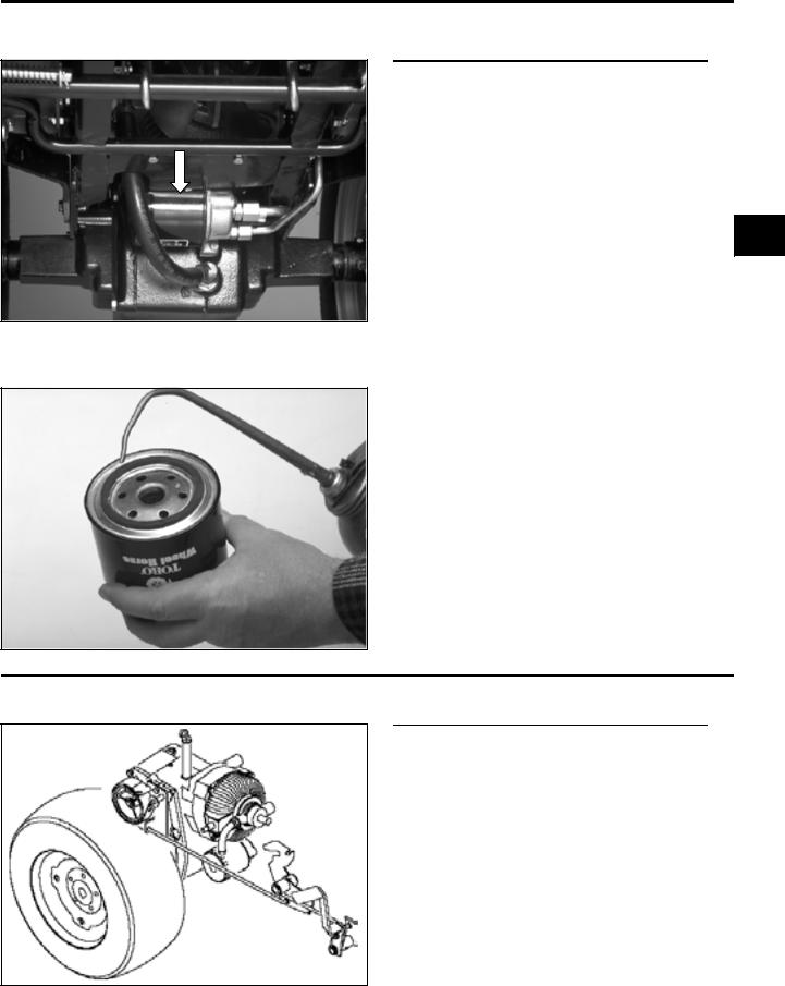
The transaxle is equipped with a 10 micron spinon oil filter. This filter should be changed after the first 50 hours of operation and then every 200 hours thereafter.
1c
When replacing the filter, coat the gasket with oil. Tighten until the gasket contacts the base, then an additional 1/2 turn.
BRAKE
General Information
The 5xi series tractor is equipped with an external band parking brake which is located on the right side of the transaxle.
When the brake pedal is pressed, the linkage returns the transmission to neutral, then applies the brake.
The band brake supplements the transmission’s dynamic braking to bring the tractor to a stop. It can also be locked in the applied position and serves as the parking brake.
5xi Series Tractor Hydraulic Service Manual |
1 - 11 |

MAINTENANCE
Adjustment
1.Place the transmission in neutral.
2.Depress the brake pedal. There should be 2” (51mm) of free travel before resistance is felt.
1c
0109-005
3.Turn the adjustment nut until the above condition is met.
CAUTION: Do not overtighten the adjustment nut.
0109-010
NEUTRAL ADJUSTMENT
General Information
The hydrostatic transmission linkage is designed to be self-centering or “return to neutral”. If the wheels continue to drive with no pressure on the control pedal (tractor creeps), neutral adjustment is required.
CAUTION: The drive shaft and hydrostatic cooling fan will be spinning. Use extreme caution to avoid making contact with
moving parts while performing this adjustment.
0144-001
1 - 12 |
5xi Series Tractor Hydraulic Service Manual |
3653-006
0144-072
0144-072
MAINTENANCE
Adjustment Procedure
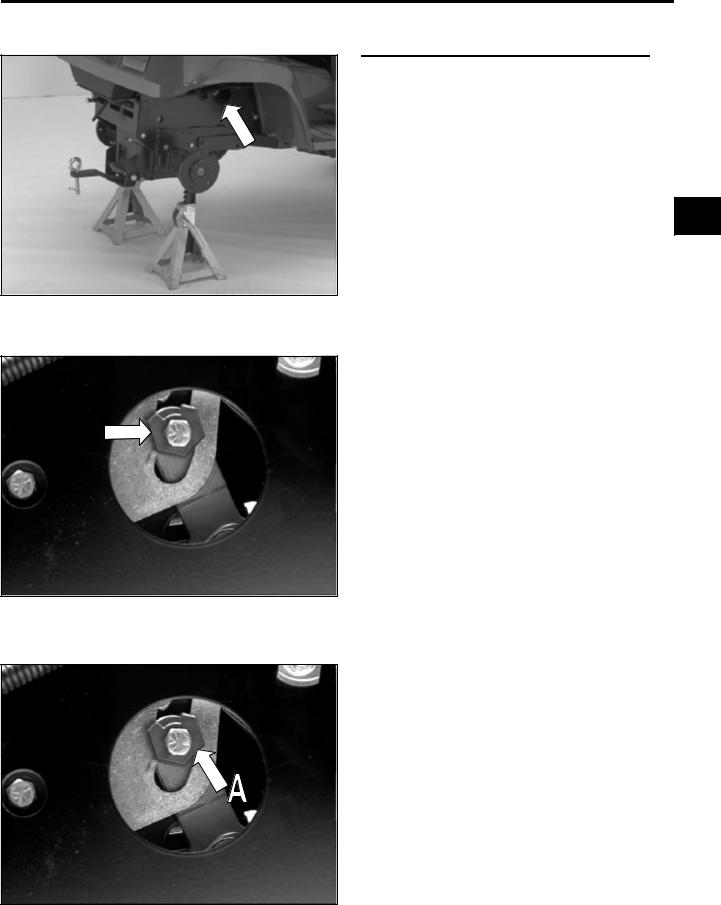
1.Place the rear axle on jack stands, and remove the rear wheels.
NOTE: Do not set the parking brake.
2.Bring the hydrostatic transmission up to operating temperature (at least 15 minutes’ operation). The neutral eccentric is accessed through the hole indicated by the
arrow. |
1c |
|
3.To gain access to the adjustment eccentric, turn the front wheels in either direction to the steering stop. This causes the linkage rod to move up, out of the way.
4.Loosen the through bolt just enough to allow rotation of the eccentric (A).
5xi Series Tractor Hydraulic Service Manual |
1 - 13 |

MAINTENANCE
5.With the engine running, rotate the eccentric until the right rear wheel hub begins to turn. Note the position of the eccentric. Rotate the eccentric in the opposite direction until the wheel hub again begins to turn.
1c
0144-071
6.Center the eccentric between these points, and tighten the through bolt while holding the eccentric.
(A)Pivot Point
NOTE: Do not turn the eccentric more than 90° in either direction. Notch in eccentric must be away from pivot point of control arm.
144-072
POWER STEERING
General Information
The 22 HP, 20 HP liquid-cooled and 23 HP diesel tractors are equipped with power steering.
This system routes pressurized transaxle fluid supplied by the hydrostatic transmission to a directional valve located at the base of the steering column. When the steering wheel is turned, this valve directs pressure to a double acting hydraulic cylinder, causing the steering plate to pivot as the cylinder extends or contracts. Tie rods attached to the steering plate turn the front spindles.
NOTE: A noisy or sluggish hydraulic system could be caused by a dirty power steering filter.
7195-029
1 - 14 |
5xi Series Tractor Hydraulic Service Manual |

0109-044
0144-16
0144-076
MAINTENANCE
When the tractor is not running, some oil will drain from the power steering system. On engine start-up, purge air from the system by turning the steering wheel fully left and right, at full engine rpm, until full steering performance is restored.
1c
Maintenance
The power steering system is equipped with an in-line filter screen. It should be cleaned after the initial 50 hours, then every 200 hours, or if the power steering gets noisy.
To clean the power steering screen:
1.Remove the left and center air intake screens.
2.Remove the screen housing from the clamp securing it to the left-hand side of the steering tower.
3.Remove the top hose first to prevent oil from back-flushing the screen.
4.Remove the hydraulic lines and seal the ends to keep out dirt.
5.Disassemble the housing and clean the screen and housing with solvent.
5xi Series Tractor Hydraulic Service Manual |
1 - 15 |

MAINTENANCE
6.Inspect the O-rings which seal the lines and housings. Replace them if there are any signs of cuts and deterioration (i.e. hardening or swelling of the rubber).
Lubricate the O-rings before reassembly.
1c
0144-086
7.Reassemble the housing, replace the lines, and secure to the steering tower.
8.Start the engine. Bleed air from the system by turning the steering wheel from stop to stop several times.
9.Check the transaxle fluid level.
0144-16
1 - 16 |
5xi Series Tractor Hydraulic Service Manual |
THEORY OF OPERATION
QUICK REFERENCE SECTION
Safety Information . . . . . . . . . . . . . . . . . . . . . . . . . . . . . . . . . . . . . . . . . . . . . . .
Specifications. . . . . . . . . . . . . . . . . . . . . . . . . . . . . . . . . . . . . . . . . . . . . . . . . . .
Maintenance . . . . . . . . . . . . . . . . . . . . . . . . . . . . . . . . . . . . . . . . . . . . . . . . . . .
TROUBLESHOOTING
Theory of Operation . . . . . . . . . . . . . . . . . . . . . . . . . . . . . . . . . . . . . . . . . . . .
Troubleshooting Tables . . . . . . . . . . . . . . . . . . . . . . . . . . . . . . . . . . . . . . . . . . .
Troubleshooting Flow Charts. . . . . . . . . . . . . . . . . . . . . . . . . . . . . . . . . . . . . . .
Hydraulic Systems Testing . . . . . . . . . . . . . . . . . . . . . . . . . . . . . . . . . . . . . . . .
REPAIR PROCEDURES
Chassis . . . . . . . . . . . . . . . . . . . . . . . . . . . . . . . . . . . . . . . . . . . . . . . . . . . . . . .
Hydrostatic Drive . . . . . . . . . . . . . . . . . . . . . . . . . . . . . . . . . . . . . . . . . . . . . . . .
Hydraulic Systems . . . . . . . . . . . . . . . . . . . . . . . . . . . . . . . . . . . . . . . . . . . . . . .
1a
1b
1c
2
3
4
5
6
7
8
5xi Series Tractor Hydraulic Service Manual |
2 - 1 |

THEORY OF OPERATION
Table of Contents
General Information . . . . . . . . . . . . . . . . . . . . . . . . . . . . . . . . . . . . . . . . . . . . . . . 2 - 3 Transmission Operation . . . . . . . . . . . . . . . . . . . . . . . . . . . . . . . . . . . . . . . . . . . . 2 - 4 Hydrostatic Transmission Flow Diagram With Power Steering . . . . . . . . . . . . . . 2 - 5 Hydrostatic Transmission Flow Diagram Without Power Steering . . . . . . . . . . . . 2 - 6 Power Steering Cylinder Hydraulic Hose Routing . . . . . . . . . . . . . . . . . . . . . . . . 2 - 7 Lift Cylinder Hydraulic Hose Routing . . . . . . . . . . . . . . . . . . . . . . . . . . . . . . . . . . 2 - 7 Hydrostatic Transmission Flow Diagram, Units Without Power Steering . . . . . . . 2 - 8
2
2 - 2 |
5xi Series Tractor Hydraulic Service Manual |

THEORY OF OPERATION
General Information
The Eaton Model 11 hydrostatic transmission, as used on the 5xi series, is equipped with an internal charge pressure valve, forward and reverse check and acceleration valves, and vibration dampening pistons. The transmission has a splined output shaft and keyed input shaft, both of which are supported by ball bearings.
2
A) |
Radial Ball-Piston Pump. |
(E) Control Shaft - Controls transmission output speed and |
|
B) |
Acceleration Valves. |
|
direction of rotation - shaft points to the right when |
C) |
Input Shaft. |
|
installed in the 5xi transaxle. |
D) Charge Pump - Charge pressure 30-90 PSI |
(F) |
Dampening Pistons - Aids in quieter unit operation. |
|
|
(2.1 - 6.2 bar). Implement lift pressure 700- |
(G) Charge Pressure Relief Valve. |
|
|
800 PSI (48.2 - 55.2 bar) with manual |
(H) Check Valve - Two used. |
|
|
steering, 725 PSI (50 bar) with power |
(I) |
Output Shaft. |
|
steering. |
(J) |
Radial Ball-Piston Motor. |
5xi Series Tractor Hydraulic Service Manual |
2 - 3 |
THEORY OF OPERATION
Transmission Operation
Transmission input shaft is driven at engine speed by drive shaft. Both charge pump and transmission pump are driven by input shaft. Charge pump draws oil from transaxle to “supercharge” transmission pump, make up for normal internal leakage, and provide a cooling oil flow. Oil travels from the outlet of the charge pump through a hydraulic hose to the power steering valve (on units equipped with power steering). Then oil flows through the open-center hydraulic lift valve and out to the oil filter adapter through another hose. After filtering, oil passes through a metal line and into the transmission.
NOTE: Lift valve noise is normal on manual steering units.
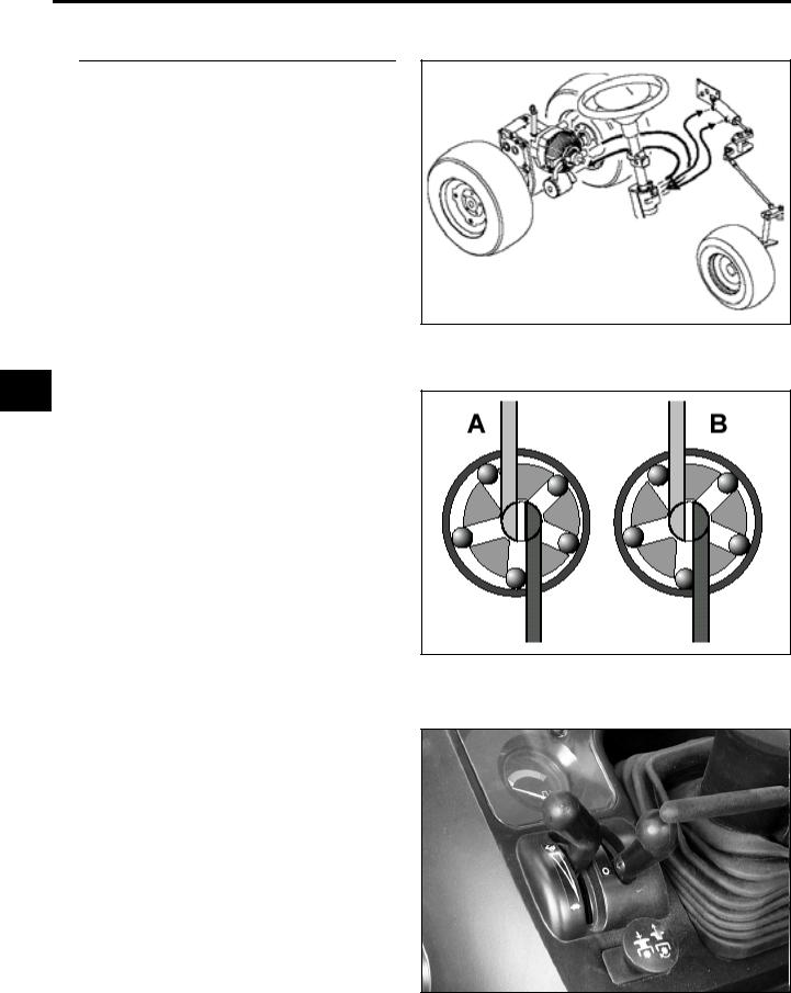
2 Pump section of transmission controls volume and direction of oil flow to motor section depending on position of motion control linkage. As the motion control lever is moved away from neutral position, the cam ring increases the displacement of the pump and the flow of oil is increased to the motor making it go faster. The motor output shaft drives the tractor axles through two reduction gears and a differential assembly. Torque is generated in direct response to load; higher pump pressure (torque) is generated as resistance to movement increases.
(A) Maximum Flow |
(B) Minimum Flow |
For optimum performance engine should be operated at full throttle, and never less than 3/4 throttle. Under high load conditions tractor should be slowed using traction pedal, which will increase output torque. This is due to lower friction and pumping losses at slower transmission output speeds, and can be compared to the effect of shifting a manual transmission to a lower gear.
7195-029
0202-100
0202-002
2 - 4 |
5xi Series Tractor Hydraulic Service Manual |

THEORY OF OPERATION
The power steering and hydraulic lift circuit are also operated by the charge pump. When the lift control valve is moved to Raise or Lower position, the charge pump output is diverted to one of the hoses attached to the lift cylinder. The other hose is connected through the lift valve to charge pressure hose leading to the oil filter, permitting bleed-off of oil on that side of lift cylinder’s piston. Implement relief valve located in control valve (manual steering) or power steering valve regulates lift system pressure at 700-800 PSI (48.2 - 55.2 bar). When this valve opens, excess oil is bled off into the charge pressure hose leading to the oil filter.
NOTE: Lift valve noise is normal on manual steering units.
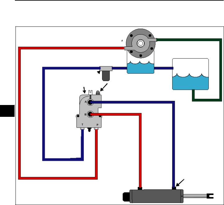
HYDROSTATIC TRANSMISSION FLOW DIAGRAM WITH POWER STEERING
|
|
A |
|
|
|
H |
|
B |
|
|
C |
J |
||
|
|
|
|
|
|
|
|
|
|
G |
D |
|
|
2 |
|
|
|
|
|
I
F E
(A) |
Charge Pump |
Red = Oil Under Pressure |
(B) Transaxle Sump |
Blue = Oil Not Under Pressure |
|
(C) Filter |
Green = Suction Line |
|
(D) Lift Valve |
|
|
(E) |
Lift Cylinder |
NOTE: Pressurization of lines at lift/steering |
(F) |
Steering Cylinder |
cylinders reverses with change in valve |
(G) Power Steering Valve - With 725 PSI (50 bar) relief valve |
actuation. |
|
(H)Charge Pressure Test Point: 30-90 PSI (2.1 - 6.2 bar)
(I)Lift Pressure Test Point: 725 PSI (50 bar)
5xi Series Tractor Hydraulic Service Manual |
2 - 5 |
THEORY OF OPERATION
HYDROSTATIC TRANSMISSION FLOW DIAGRAM WITHOUT POWER STEERING
A

C B
I
G
D  F
F
2
Illustrator Files/5xi wo ps.eps
H
E
(A) |
Charge Pump |
Red = Oil Under Pressure |
(B) Transaxle Sump |
Blue = Oil Not Under Pressure |
|
(C) Filter |
Green = Suction Line |
|
(D) Lift Valve |
|
|
(E) |
Lift Cylinder |
NOTE: Pressurization of lines at lift/steering |
(F) |
Relief Valve |
cylinders reverses with change in valve |
|
Setting on manual steering units 700-800 PSI (48.2 - 55.2 bar) |
actuation. Lift valve noise is normal. |
(G)Charge Pressure Test Point: 30-90 PSI (2.1 - 6.2 bar)
(H)Lift Pressure Test Point: 700-800 PSI (48.2 - 55.2 bar)
2 - 6 |
5xi Series Tractor Hydraulic Service Manual |

THEORY OF OPERATION
POWER STEERING CYLINDER HYDRAULIC HOSE ROUTING
2
LIFT CYLINDER HYDRAULIC HOSE ROUTING
5xi Series Tractor Hydraulic Service Manual |
2 - 7 |
THEORY OF OPERATION
Flow diagrams show hydraulic circuits inside hydrostatic unit and illustrate high and low pressure areas during operation.
Pressurized oil from the charge pump is maintained between 30 and 90 PSI (2.1 - 6.2 bar) by the charge relief valve located inside the hydrostatic unit. When the valve opens, excess oil pressure is bled back to the transaxle sump through a hole in the housing.
The charge pump oil enters the transmission pump section, which is turning at engine speed, and “supercharges” it.
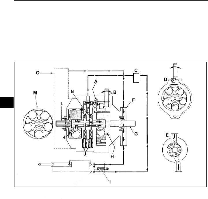
HYDROSTATIC TRANSMISSION FLOW DIAGRAM, UNITS WITHOUT POWER STEERING
2
(A)Charge Pressure Relief Valve.
(B)Motion Control Shaft.
(C)Filter.
(D)Cam Ring - Radial ball-piston hydraulic pump. (variable displacement).
(E)Charge Pump - Transmission charge pressure 3090 PSI (2.1 - 6.2 bar). Implement lift system pressure 700 PSI (48.2 bar).
(F)Charge Pump.
(G)Input Shaft.
(H)Hydraulic Pump.
(I)Hydraulic Lift Control Valve - With 700 PSI (48.2 bar) relief valve.
(J)Acceleration Valves.
(K)Hydraulic Motor.
(L)Output Shaft.
(M)Radial Ball-Piston Hydraulic Motor - Fixed Displacement.
(N)Forward/Reverse Check Valves.
(O)Transaxle Sump.
2 - 8 |
5xi Series Tractor Hydraulic Service Manual |

3094-042
0202-003
0202-004
THEORY OF OPERATION
The operator controls the transmission by moving the control shaft connected to the cam ring within the pump. With the control shaft in neutral, or its centered position, no flow is generated by the pump and, therefore, the motor portion is at rest.
When the control shaft is moved from neutral in the “forward” direction, the cam ring in the pump is moved off center and the pump ball-pistons create a flow of fluid. The position of the control shaft/cam ring is infinitely variable and any flow rate is possible up to maximum cam ring movement/maximum pump displacement.
Flow created by pump moves to fixed |
2 |
|
displacement motor through internal |
|
|
|
||
passageways. Because the motor is a fixed |
|
|
displacement unit, the motor requires a specific |
|
|
volume of fluid for it to make one complete |
|
|
revolution. |
|
|
(A) Pump |
(C) High Pressure |
|
(B) Motor |
(D) Low Pressure |
|
When the control shaft is moved from neutral to “reverse” direction, the cam ring is swung off center to the opposite side of the pump and the flow from the pump is “reversed”. This flow is directed to the other side of the motor causing its output shaft to rotate in the opposite direction. The pump input shaft always rotates in one direction, dictated by the engine, while the motor output shaft rotates in either direction, depending on the direction of flow from the pump.
Pump discharge flow is high pressure (dictated by load) fluid. Flow returned from the motor to the pump is low (or charge) pressure fluid.
(A) |
Pump |
(C) Low Pressure |
(B) |
Motor |
(D) High Pressure |
5xi Series Tractor Hydraulic Service Manual |
2 - 9 |

THEORY OF OPERATION
Due to internal leakage, fluid being returned to the inlet side of the pump from the exhaust side of the motor is less than required by the pump. To replace this needed fluid, check valves are located in each side of closed loop. The check valve located on the low pressure side of the pump will open allowing fluid to enter loop, from the charge pump circuit, to make up leakage losses.
(A) Pump |
(D) High Pressure |
(B) Motor |
(E) Charge Pump |
(C) Low Pressure |
(F) Check Valves |
0202-005
2 Internal acceleration valves are used in both forward and reverse directions. These valves are spring loaded to close “slowly” as pressure (load) increases. These valves control the rate of acceleration of the motor output shaft, assist in providing a positive neutral, and permit hand pushing the tractor without operating the engine.
(A) |
From Sump |
(H) Hydraulic Motor |
|
(B) Charge Pump |
(I) |
Output Shaft |
|
(C) Input Shaft |
(J) |
Forward/Reverse |
|
(D) To Lift |
|
Check Valves |
|
(E) Hydraulic Pump |
(K) From Lift |
||
(F) |
Acceleration |
(L) |
Charge Pressure |
|
Valves |
|
Relief Valve |
(G) To Sump |
(M) Motion Control Shaft |
||
0202-006
In operation, as the tractor’s motion control lever is moved out of neutral, the appropriate acceleration valve bleeds off some of the high pressure oil before it closes. This initial temporary pressure reduction results in smoother tractor acceleration from a standstill.
(A)Dampening Piston
(B)Pump
(C)Control Shaft
(D)Aux. Hyd. Valve
(E)Filter
(F)Charge Pump
(G)Check Valve
(H)Acceleration Valves
(I)Charge Relief Valve
(J)Motor
(K)High Pressure
(L)Low Pressure (30-90 PSI)
(M)Transaxle Sump
(N)Lift System Pressure (700 PSI (48 bar) with manual steering; 725 PSI (50 bar) with power steering
0202-007
2 - 10 |
5xi Series Tractor Hydraulic Service Manual |
 Loading...