


Toro 72043, 72046, 72048, 72063, 72064 Service Manual
...TUFF-TORQ K61A TRANSAXLE SERVICE MANUAL
Table of Contents – Page 1 of 2
SAFETY INFORMATION
SPECIFICATIONS
REMOVING THE TRANSAXLE FROM THE TRACTOR
TRANSAXLE DISASSEMBLY AND INSPECTION
PINION
DIFFERENTIAL GEAR
CENTER CASE
MOTOR SHAFT
PUMP SHAFT
TRANSAXLE ASSEMBLY AND ADJUSTMENT BYPASS RETURN
BRAKE INTERLOCK
NEUTRAL ADJUST ECCENTRIC PUMP SHAFT
SWASH PLATE
PUMP CYLINDER BLOCK MOTOR SHAFT CENTER CASE
MOTOR SHAFT AND CENTER CASE INSTALLATION DIFFERENTIAL GEAR
AXLE SHAFTS AND DIFFERENTIAL INSTALLATION PINION
TRANSAXLE CASE BRAKE
DAMPER
BLEEDING AIR FROM THE OIL CIRCUIT UNIT OUT OF TRACTOR
UNIT IN TRACTOR
TRANSAXLE NEUTRAL ADJUSTMENT
BELTS AND LINKAGE
BELT REPLACEMENT
BELT ROUTING - BOTTOM VIEW
REASSEMBLY
BELT ADJUSTMENT
BRAKE LINKAGE
FOOT BRAKE
DESCRIPTION AND OPERATION
ADJUSTMENT
PARKING BRAKE
DESCRIPTION AND OPERATION
TRANSAXLE BRAKE
DESCRIPTION AND OPERATION
BRAKE BAND ADJUSTMENT
TUFF-TORQ K61A TRANSAXLE SERVICE MANUAL
Table of Contents – Page 2 of 2
BELTS AND LINKAGE -Continued HYDROSTATIC CONTROL LINKAGE
DESCRIPTION AND OPERATION LUBRICATION
PEDAL ADJUSTMENT CRUISE CONTROL
DESCRIPTION AND OPERATION COMPONENTS
PLATE-HYDROSTATIC CONTROL ARM AND HOUSING BRACKET MAGNET
MAGNET
BRAKE SWITCH AND MOUNTING BRACKET RELAY
TROUBLESHOOTING
Tuff-TorqR
K61A Transaxle
About This Manual
This manual was written expressly for servicing Tuff Torq K61A transaxles, as used in 1994--1999 260-Series Toro Wheel Horse tractors. The Toro Company has made every effort to make the information in this manual complete and correct.
This manual was written for the service technician; basic mechanical/electrical skills are assumed. The Contents page lists the systems and the related topics covered in this manual.
We hope that you will find this manual a valuable addition to your service shop. If you have any questions or comments regarding this manual, please contact us at the following address:
The Toro Company
Consumer Service Department
8111 Lyndale Avenue South
Bloomington, MN 55420--1196
Portions of this manual are reprinted courtesy of Tuff Torq Corporation and New Holland North America.
The Toro Company reserves the right to change product specifications or this manual without notice.
COPYRIGHT – ALL RIGHTS RESERVED
The Toro Company – 2000
Bloomington, MN 55420 – U.S.A
1
Contents
Safety Information . . . . . . . . . . . . . . . . . . . . . . . . . . . . . 3 Specifications . . . . . . . . . . . . . . . . . . . . . . . . . . . . . . . . . 4 Removing the Transaxle from the Tractor . . . . . . . . 5 Transaxle Disassembly and Inspection . . . . . . . . . . 6
Pinion . . . . . . . . . . . . . . . . . . . . . . . . . . . . . . . . . . . . . . . . . . 14 Differential Gear . . . . . . . . . . . . . . . . . . . . . . . . . . . . . . . . . 14 Center Case . . . . . . . . . . . . . . . . . . . . . . . . . . . . . . . . . . . . 15 Motor Shaft . . . . . . . . . . . . . . . . . . . . . . . . . . . . . . . . . . . . . 15 Pump Shaft . . . . . . . . . . . . . . . . . . . . . . . . . . . . . . . . . . . . . 16
Transaxle Assembly and Adjustment . . . . . . . . . . . . 17
Bypass Return . . . . . . . . . . . . . . . . . . . . . . . . . . . . . . . . . . 17 Brake Interlock . . . . . . . . . . . . . . . . . . . . . . . . . . . . . . . . . . 17 Neutral Adjust Eccentric . . . . . . . . . . . . . . . . . . . . . . . . . . 19 Pump Shaft . . . . . . . . . . . . . . . . . . . . . . . . . . . . . . . . . . . . . 20 Swash Plate . . . . . . . . . . . . . . . . . . . . . . . . . . . . . . . . . . . . 20 Pump Cylinder Block . . . . . . . . . . . . . . . . . . . . . . . . . . . . . 21 Motor Shaft . . . . . . . . . . . . . . . . . . . . . . . . . . . . . . . . . . . . . 22 Center Case . . . . . . . . . . . . . . . . . . . . . . . . . . . . . . . . . . . . 23 Motor Shaft and Center Case Installation . . . . . . . . . . . 23 Differential Gear . . . . . . . . . . . . . . . . . . . . . . . . . . . . . . . . . 25 Axle Shafts and Differential Installation . . . . . . . . . . . . . 25 Pinion . . . . . . . . . . . . . . . . . . . . . . . . . . . . . . . . . . . . . . . . . . 26 Transaxle Case . . . . . . . . . . . . . . . . . . . . . . . . . . . . . . . . . 27 Brake . . . . . . . . . . . . . . . . . . . . . . . . . . . . . . . . . . . . . . . . . . 28 Damper . . . . . . . . . . . . . . . . . . . . . . . . . . . . . . . . . . . . . . . . 29 Bleeding Air from the Oil Circuit . . . . . . . . . . . . . . . . . . . 29
Unit Out of Tractor . . . . . . . . . . . . . . . . . . . . . . . . . . 29 Unit in Tractor . . . . . . . . . . . . . . . . . . . . . . . . . . . . . . 29 Transaxle Neutral Adjustment . . . . . . . . . . . . . . . . . . . . . 30
Belts and Linkage . . . . . . . . . . . . . . . . . . . . . . . . . . . . . . 31
Belt Replacement . . . . . . . . . . . . . . . . . . . . . . . . . . . . . . . 31 Belt Routing—Bottom View . . . . . . . . . . . . . . . . . . . . . . . 32 Reassembly . . . . . . . . . . . . . . . . . . . . . . . . . . . . . . . . . . . . 32 Belt Adjustment . . . . . . . . . . . . . . . . . . . . . . . . . . . . . . . . . 33 Brake Linkage . . . . . . . . . . . . . . . . . . . . . . . . . . . . . . . . . . 35
Foot Brake . . . . . . . . . . . . . . . . . . . . . . . . . . . . . . . . . 35 Description and Operation . . . . . . . . . . . . . . . 35 Adjustment . . . . . . . . . . . . . . . . . . . . . . . . . . . . 35 Parking Brake . . . . . . . . . . . . . . . . . . . . . . . . . . . . . . 35 Description and Operation . . . . . . . . . . . . . . . 35
Transaxle Brake . . . . . . . . . . . . . . . . . . . . . . . . . . . . . . . . . 36 Description and Operation . . . . . . . . . . . . . . . . . . . . 36 Brake Band Adjustment . . . . . . . . . . . . . . . . . . . . . . . . . . 37 Hydrostatic Control Linkage . . . . . . . . . . . . . . . . . . . . . . . 38 Description and Operation . . . . . . . . . . . . . . . . . . . . 38 Lubrication . . . . . . . . . . . . . . . . . . . . . . . . . . . . . . . . . 38 Pedal Adjustment . . . . . . . . . . . . . . . . . . . . . . . . . . . . . . . 38
Cruise Control . . . . . . . . . . . . . . . . . . . . . . . . . . . . . . . . . . 39
Description and Operation . . . . . . . . . . . . . . . . . . . . 39
Components . . . . . . . . . . . . . . . . . . . . . . . . . . . . . . . 39
Plate-Hydrostatic Control Arm and Housing . . . . . 39
Bracket Magnet . . . . . . . . . . . . . . . . . . . . . . . . . . . . . 40
Magnet . . . . . . . . . . . . . . . . . . . . . . . . . . . . . . . . . . . . 40
Brake Switch and Mounting Bracket . . . . . . . . . . . 40
Relay . . . . . . . . . . . . . . . . . . . . . . . . . . . . . . . . . . . . . . 40
Troubleshooting . . . . . . . . . . . . . . . . . . . . . . . . . . . . . . . 41
Contents |
2 |
Tuff Torq Model K61A Hydrostatic Transaxle |

Safety Information
This symbol means WARNING or
PERSONAL SAFETY INSTRUCTION—
read the instruction because it has to do
with your safety. Failure to comply with
the instruction may result in personal injury or even death.
This manual is intended as a service and repair manual only. The safety instructions provided herein are for troubleshooting, service, and repair of the Tuff Torq
model K61A hydrostatic transaxle. The tractor and attachment operator’s manuals contain safety information and operating tips for safe operating practices. Operator’s manuals are available through your local Toro distributor or:
The Toro Company Publications Department 8111 Lyndale Avenue South Bloomington, MN 55420--1196
Think Safety First
Avoid unexpected starting of engine...
Always turn off the engine and disconnect the spark plug wire(s) before cleaning, adjusting, or repair.
Avoid asphyxiation...
Never operate an engine in a confined area without proper ventilation.
Avoid injury from high pressure oil...
Keep body and hands away from pin hole leaks or nozzles that eject high pressure oil. Use cardboard or paper to locate hydraulic leaks. Oil escaping under high pressure can penetrate the skin and cause injury. Oil accidentally injected into the skin must be surgically removed within a few hours by a doctor familiar with this form of injury or gangrene may result.
Avoid laceration and amputations...
Stay clear of all moving parts whenever the engine is running. Treat all normally moving parts as if they were moving whenever the engine is running or has the potential to start.
Avoid burns...
Do not touch the engine, muffler, or other components which may increase in temperature during operation, while the unit is running or shortly after it has been running.
Avoid fires and explosions...
Avoid spilling fuel and never smoke while working with any type of fuel or lubricant. Wipe up any spilled fuel or oil immediately. Never remove the fuel cap or add fuel when the engine is running. Always use approved, labeled containers for storing or transporting fuel and lubricants.
Avoid injury from batteries...
Battery acid is poisonous and can cause burns. Avoid contact with skin, eyes, and clothing. Battery gases can explode. Keep cigarettes, sparks, and flames away from the battery.
Avoid injury due to inferior parts...
Use only original equipment parts to ensure that important safety criteria are met.
Avoid injury to bystanders...
Always clear the area of bystanders before starting or testing powered equipment.
Avoid injury due to projectiles...
Always clear the area of sticks, rocks, or any other debris that could be picked up and thrown by the powered equipment.
Avoid modifications...
Never alter or modify any part unless it is a factory approved procedure.
Avoid unsafe operation...
Always test the safety interlock system after making adjustments or repairs on the machine.
Tuff Torq Model K61A Hydrostatic Transaxle |
3 |
Safety Information |
Specifications
Axle Torque Output |
|
Rated: . . . . . . . . . . . . . . . . . . . . . . . . |
215 ft. lb. (290 NSm) |
Peak: . . . . . . . . . . . . . . . . . . . . . . . . . |
654 ft. lb. (880 NSm) |
Maximum Input Speed . . . . . . . . . . . . . |
3000 RPM |
Input Shaft Size . . . . . . . . . . . . . . . . . . . |
0.58 in. (14.85mm) |
Reduction Ratio . . . . . . . . . . . . . . . . . . . |
26.97:1 |
Axle Shaft Size . . . . . . . . . . . . . . . . . . . . |
1.0 in. (25.4mm) |
Maximum Static Weight on Axle . . . . |
584 lb. (265kg) |
Weight — Dry . . . . . . . . . . . . . . . . . . . . . |
38 lb. (17.5kg) |
Brake . . . . . . . . . . . . . . . . . . . . . . . . . . . . . |
Dry Band |
Brake Capacity . . . . . . . . . . . . . . . . . . . . |
288 ft. lb. (390 NSm) at 55 lb. (245NSm) Brake Arm Force |
Differential . . . . . . . . . . . . . . . . . . . . . . . . |
Automotive-Type Bevel Gears |
Gears . . . . . . . . . . . . . . . . . . . . . . . . . . . . |
Heat-Treated |
Housings . . . . . . . . . . . . . . . . . . . . . . . . . |
Aluminum Die Castings |
Tow Valve . . . . . . . . . . . . . . . . . . . . . . . . |
Standard (Brake Release) |
Oil . . . . . . . . . . . . . . . . . . . . . . . . . . . . . . . |
10W--30 API Service Class H or Higher |
Oil Capacity . . . . . . . . . . . . . . . . . . . . . . |
3.5 qt. (3.3 liter) |
Ground Speed |
|
Maximum Forward . . . . . . . . . . . . . |
5.3 MPH (8.5km/hr) |
Maximum Reverse . . . . . . . . . . . . . |
2.3 MPH (3.7km/hr) |
Specifications |
4 |
Tuff Torq Model K61A Hydrostatic Transaxle |

Removing the Transaxle from the Tractor
Working from the bottom of the tractor, remove the transaxle drive belt tension spring and drive belt from the transaxle pulley.
Remove the access panel from the rear of the tractor, to expose the fuel tank/transaxle.
Figure 1
Disconnect the brake rod, control rod, tow valve rod, and reservoir hose from the top of the transaxle.
Support the rear of the tractor with jack stands and remove the rear wheels.
Remove the two bolts securing the transaxle support rods to the tractor frame.
Remove the four nuts from the U-bolts which hold the two axle shafts to the frame.
Remove the transaxle and place it upright on the work bench.
Remove the fan and spacer from the input pulley (three cap screws).
Remove the pulley from the shaft (one snap ring).
Figure 2
Tuff Torq Model K61A Hydrostatic Transaxle |
5 |
Removing the Transaxle from the Tractor |
Transaxle
Disassembly and
Inspection
Begin disassembly and inspection of the transaxle by thoroughly cleaning the outside surface of the transmission.
IMPORTANT: Clean your work area thoroughly and cover the workbench with clean paper. This is extremely important as just one grain of sand can cause a hydrostatic transmission to fail.
Remove the drain bolt from the bottom center and drain the oil from the transaxle sump.
Figure 3
Remove the pressure fill plug and drain the oil from the rotating groups.
Figure 4
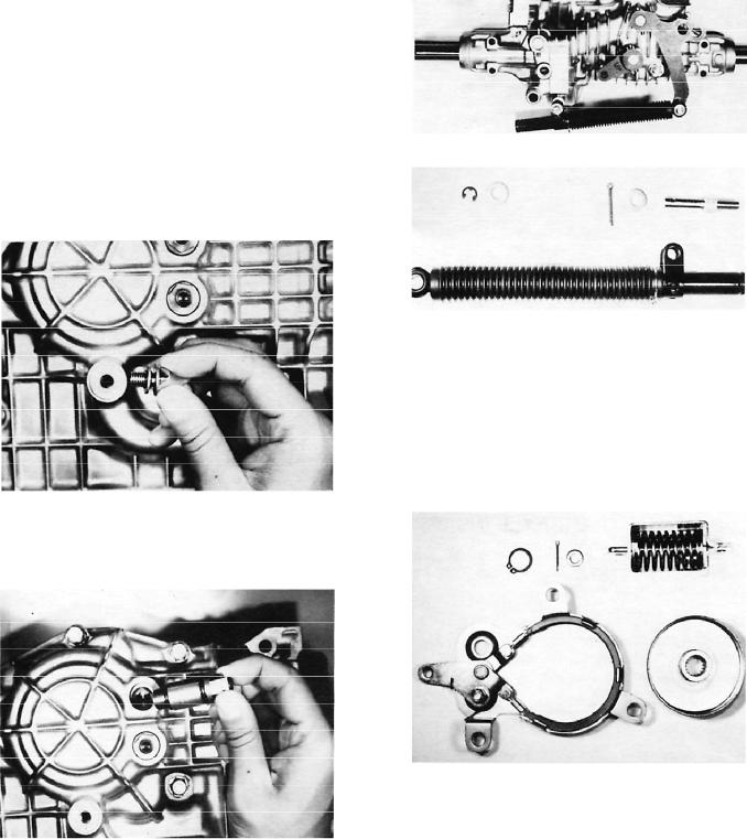
Remove the shock absorber by detaching the E clip, washer, and cotter pin and its washer. Later models use a spring clip retainer to secure the shock absorber.
Figure 5
Figure 6
Remove the band brake assembly and brake rod component by taking out the cotter pin, washer, and three 12mm bolts. Replace the assembly if the friction material or actuating parts are worn or damaged.
Remove the ring and brake drum.
IMPORTANT: The brake drum and brake band must be free from oil or dust.
Figure 7
Transaxle Disassembly and Inspection |
6 |
Tuff Torq Model K61A Hydrostatic Transaxle |
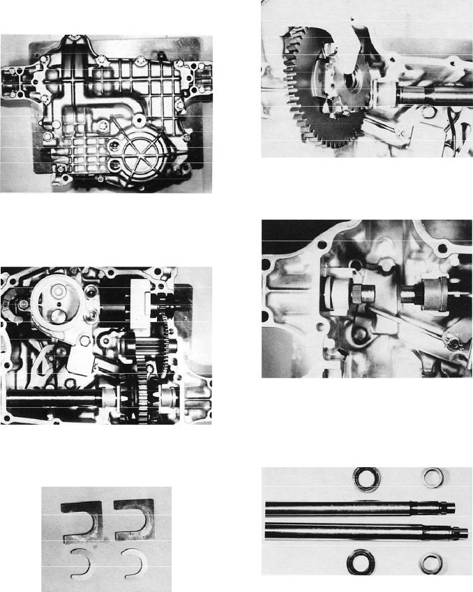
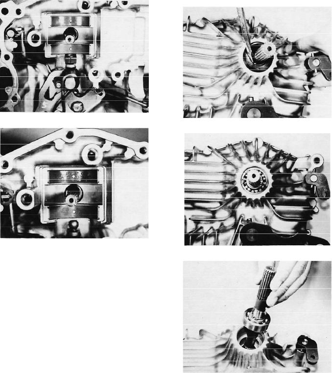
Open the transaxle case by taking out the 13 perimeter 12mm bolts and the single center bolt. Pry the bottom half of the case free from the top half, using care not to damage the seating surface.
Figure 8
Lift the pinion shaft assembly from the upper case. There is a ball bearing on one end of the shaft and a bushing on the other end.
Figure 9
Remove the collar and ring from the left and right axle shaft.
Figure 10
Remove the differential gear assembly.
Figure 11
Remove the left and right axle shaft and two bushings from the upper case.
Figure 12
Remove the two seals from the upper case. Remove the axle bearings if replacing.
Inspect all parts for wear or damage and replace if necessary.
Figure 13
Tuff Torq Model K61A Hydrostatic Transaxle |
7 |
Transaxle Disassembly and Inspection |
Measure the inside diameter of the bushings and the outside diameter of the left and right axle shaft.
Table 1
Measurement
Bushings -
Inside Diameter
Axle Shaft
Outside Diameter
Clearance
Maximum Wear Limit
Should be:
22.06-22.15mm
(.868-.872″)
21.98-22mm
(.865-.866″)
0.08-0.17mm
(.003-.006″)
0.5mm (.019″)
Measure the inside diameter of the axle bores in the housing and the outside diameter of the left and right axle shaft.
Table 2
Measurement
Housing Axle Bore --
Inside Diameter
Axle Shaft
Outside Diameter
Clearance
Maximum Wear Limit
Should be:
25.44-25.53mm
(1.001-1.005″)
25.32-25.38mm
(.996-.999″)
0.06-0.21mm
(.002-.008″)
0.5mm (.019″)
Disconnect the C arm from the push valve bypass shaft.
Remove the two push pins, springs, and valves from the center case.
Figure 15
Remove sleeve A1, sleeve A2, the two backup rings, packings, balls, ball holders, springs, and bypass holders, using air pressure if necessary.
Note: Remove the two check valve assemblies only if necessary (leaking, sticking, or if extra-thorough cleaning is necessary). Air pressurization will remove one valve; the other can be pushed out from behind, after the center section is removed.
1
2 |
3 |
Take the filter out of the center case.
Note: Replace the filter whenever transaxle is disassembled for service.
Figure 14
1.Valve A1
2.Valve A2
Figure 16
3.Pressurize with air to remove valves, if needed (pressure fill plug shown installed, with allen head plug removed).
Transaxle Disassembly and Inspection |
8 |
Tuff Torq Model K61A Hydrostatic Transaxle |

Carefully inspect the packings (o-rings) to ensure they are not deformed, cut, or scratched. Use new packings on reassembly.
IMPORTANT: When removing the sleeves, note that their valves are different, and therefore not interchangeable. The A1 valve, located farthest from the axle, has a small hole in it, in addition to the large hole in the center. For reassembly purposes, mark the port from which this valve is removed.
1
Figure 17
1. Note hole
Loosen the three bolts and remove the magnet from the center case. Clean the magnet thoroughly; use air pressure if necessary.
Figure 18
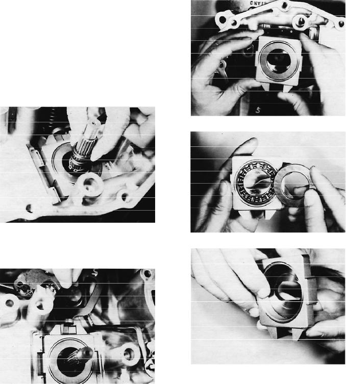
Make a mark on the top of the motor thrust bearing housing, for easy identification during reassembly.
Remove the motor shaft assembly, along with the center case assembly, from the upper case.
IMPORTANT: Pay close attention to the contact surfaces of the center case and cylinder blocks to prevent damage.
Remove the cylinder block from the pump shaft.
IMPORTANT: Be sure the pistons do not fall out of the block during removal.
Figure 20
Inspect the five cylinder bores for burrs or scoring. The cylinder block and center section must be replaced if any scratch is deep enough to catch on a fingernail.
Figure 21
Inspect the five pistons and all parts of the cylinder block assembly for wear or damage.
Replace the center case and both cylinder block assemblies if any cylinder block assembly parts are damaged.
Figure 19 |
|
Figure 22 |
Tuff Torq Model K61A Hydrostatic Transaxle |
9 |
Transaxle Disassembly and Inspection |
Measure the clearance between the swash plate and shift blocks.
Replace both shift blocks and the swash plate with new parts if they are beyond the maximum wear limit.
Table 3
Measurement |
Should be: |
|
|
Clearance |
0.01-0.11mm |
|
(.0003-.004″) |
|
|
Maximum Wear Limit |
0.15mm (.005″) |
|
|
Remove the spring and ring from the pump shaft.
Figure 23
Remove the swash plate subassembly from the pump shaft.
Figure 24
Inspect the swash plate, thrust bearing, thrust plates, and bushing for wear or damage. Replace with new parts if necessary.
Figure 25
Figure 26
Figure 27
Transaxle Disassembly and Inspection |
10 |
Tuff Torq Model K61A Hydrostatic Transaxle |
Remove the shift blocks from the control shaft and inspect them for wear or damage. Replace if necessary.
Figure 28
Figure 29
Remove the two metal thrust pads from the upper case and inspect them for wear or damage.
Replace both thrust pads with new parts if the maximum wear limit is exceeded.
Table 4
Measurement |
Should be: |
|
|
Thickness |
1.45-1.55mm |
|
(.057-0.61″) |
|
|
Maximum Wear Limit |
1.30mm (.051″) |
|
|
Remove the input shaft, seal, and bearing from the upper case. Remove oil seal and large snap ring from the upper case. Remove the input shaft and bearing from the case.
Figure 30
Figure 31
Figure 32
Tuff Torq Model K61A Hydrostatic Transaxle |
11 |
Transaxle Disassembly and Inspection |

Note: If servicing a transaxle with low to moderate use, it is not necessary to disassemble or remove any of the levers or linkages from the upper case, unless a part is damaged or there is an oil leak. If doing a complete rebuild, all shafts should be removed, inspected, and packings (o-rings) replaced. If leaving the shafts in place, avoid excessive use of cleaning solvent on the upper case half, and do not use solvent that will damage the packings.
Detach the torsion spring from the control shaft.
Figure 33
Remove the roll pin and lever from the control shaft subassembly and the lock nut from the neutral adjusting fulcrum.
Figure 34
Inspect the control shaft, fulcrum, and torsion spring for wear or damage and replace if necessary.
Figure 36
Inspect the packings (o-rings) to ensure that they are not cut, scratched, or deformed.
Figure 37
Drive the roll pin from the brake arm secured to the internal brake shaft.
Remove the brake arm from the brake shaft.
Figure 35 |
|
Figure 38 |
|
|
|
Transaxle Disassembly and Inspection |
12 |
Tuff Torq Model K61A Hydrostatic Transaxle |
 Loading...