


INSTALLATION SETUP MANUAL
NETWORK AUDIO ADAPTERS NX-100
NX-100S
Thank you for purchasing TOA's Network Audio Adapter.
Please carefully follow the instructions in this manual to ensure long, trouble-free use of your equipment.

2
TABLE OF CONTENTS
1. GENERAL DESCRIPTION ......................................................................................... 1-2
2. FEATURES ..................................................................................................................... 1-2
3. NOMENCLATURE AND FUNCTIONS
[Front] .................................................................................................................................. 1-3
[Rear] ................................................................................................................................... 1-4
4. SETTING TASK FLOWS ............................................................................................ 1-6
1. CONNECTIONS
1.1. Power Source Connection
1.1.1. When using a 24 V DC power source ......................................... 2-2
1.1.2. When using the AC adapter ............................................................................... 2-2
1.1.3. When simultaneously using the 24 V DC power supply and the AC adapter
...................................................................................................... 2-2
1.2. Terminal Connections ................................................................................................... 2-3
2. CONNECTIONS TO TERMINAL PLUGS .............................................................. 2-5
3. RACK MOUNTING ....................................................................................................... 2-6
4. MAC ADDRESSES AND INSTALLATION LOCATIONS .................................. 2-7
5. SOFTWARE INSTALLATION
5.1. System Conditions ........................................................................................................ 2-8
5.2. Activating the Setup Launcher ...................................................................................... 2-8
5.3. Installing Java Runtime Environment ........................................................................... 2-9
5.4. Installing the NX-100 Software
5.4.1. Installation procedures ..................................................................................... 2-11
5.4.2. Update information ........................................................................................... 2-14
5.4.3. Installation folder configuration ......................................................................... 2-15
5.5. Uninstalling Each Software ......................................................................................... 2-15
1. GENERAL DESCRIPTION
1.1. What is the NX-100 Setup Program? ........................................................................... 3-2
1.2. About Network Settings ................................................................................................ 3-2
1.3. Backing-Up Setting Files .............................................................................................. 3-2
1.4. Cautions Concerning Setting Updates ......................................................................... 3-2
Chapter 3: SYSTEM SETTINGS (NX-100 SETUP PROGRAM)
NX-100 only
NX-100 only
Chapter 2: UNIT AND SOFTWARE INSTALLATIONS
Chapter 1: BEFORE INSTALLATIONS AND SETTINGS

3
2. SETUP SOFTWARE CONFIGURATION AND SETTING ITEMS .................. 3-3
3. SETTING PROCEDURE ............................................................................................. 3-4
4. STARTUP OF INSTALLATION SETTING PROGRAM ..................................... 3-6
5. UNIT SCANNING TOOL
5.1. Screen Description ....................................................................................................... 3-8
5.2. Menu
5.2.1. File ...................................................................................................................... 3-9
5.2.2. Scan ................................................................................................................... 3-9
5.2.3. Help .................................................................................................................. 3-10
5.3. Buttons ....................................................................................................................... 3-10
5.4. Scanning Units ........................................................................................................... 3-10
5.5. Changing the Unit Setting Values ............................................................................... 3-11
5.6. Automatic IP Address Assignment ............................................................................. 3-11
5.7. Subnet Mask and Default Gateway Settings .............................................................. 3-12
6. SYSTEM SETTING TOOL
6.1. Screen Description ..................................................................................................... 3-13
6.2. Menu
6.2.1. File .................................................................................................................... 3-14
6.2.2. Edit ................................................................................................................... 3-14
6.2.3. Setting .............................................................................................................. 3-14
6.2.4. Help .................................................................................................................. 3-14
6.2.5. Buttons ............................................................................................................. 3-15
6.3. Network Setting .......................................................................................................... 3-16
6.4. Broadcast Spec Setting .............................................................................................. 3-18
6.5. Broadcast Pattern Setting
6.5.1. Setting new broadcast patterns ........................................................................ 3-20
6.5.2. Editing broadcast patterns ................................................................................ 3-22
6.6. Contact Setting
6.6.1. Contact input setting ......................................................................................... 3-23
6.6.2. Contact output setting ...................................................................................... 3-25
6.7. Serial Bridge Setting ........................................................................... 3-27
6.8. System Settings .......................................................................................................... 3-29
6.9. Saving the Unit Setting Files ...................................................................................... 3-29
6.10. Reopening Unit Setting Files .................................................................................... 3-30
6.11. Downloading the Operation Logs ............................................................................. 3-30
6.12. Uploading Unit Setting Files ..................................................................................... 3-30
6.13. Downloading Unit Setting Files ................................................................................. 3-30
6.14. Updating Firmware ................................................................................................... 3-30
7. CHANGING THE SYSTEM NAME AND PASSWORD ................................... 3-31
NX-100 only

4
1. OUTLINE OF SETTING USING BROWSER ........................................................ 4-2
2. SETTINGS ....................................................................................................................... 4-2
3. NETWORK SETTING .................................................................................................. 4-4
4. BROADCAST SPEC SETTING ................................................................................ 4-6
5. BROADCAST PATTERN SETTING ........................................................................ 4-9
5.1. Pattern Selection Area ................................................................................................ 4-10
5.2. Pattern Edit Area
5.2.1. Pattern addition ................................................................................................ 4-10
5.2.2. Pattern editing .................................................................................................. 4-12
6. CONTACT SETTING .................................................................................................. 4-13
6.1. Contact Input Setting .................................................................................................. 4-14
6.2. Contact Output Setting ............................................................................................... 4-16
7. SERIAL BRIDGE SETTING ........................................................ 4-18
8. LOG MANAGEMENT ................................................................................................. 4-20
8.1. Operation Log ............................................................................................................. 4-21
8.2. Saving Operation Logs ............................................................................................... 4-23
8.3. Stream Logs ............................................................................................................... 4-24
8.4. Operation Status ......................................................................................................... 4-26
9. SYSTEM MANAGEMENT ........................................................................................ 4-27
1. NX-100 OPERATION PROGRAM SUMMARY .................................................... 5-2
2. STARTUP AND INITIAL SCREEN .......................................................................... 5-2
3. OPERATION SCREEN DESCRIPTION ................................................................. 5-3
4. MENU
4.1. File ................................................................................................................................ 5-4
4.2. Settings ......................................................................................................................... 5-4
4.3. Help .............................................................................................................................. 5-4
5. SETTING PROCEDURES USING THE OPERATION PROGRAM ............... 5-5
6. UNIT SETTING ADDITION ........................................................................................ 5-6
7. EDITTING THE BUTTON LAYOUT ......................................................................... 5-8
8. SETTING THE SELECTION BUTTON CONTENTS ........................................ 5-10
9. SETTING THE GROUP BUTTON CONTENTS ................................................. 5-13
10. ERROR MESSAGES ............................................................................................... 5-15
Chapter 5: OPERATION SETTINGS (NX-100 OPERATION PROGRAM)
NX-100 only
Chapter 4: SYSTEM SETTINGS (SETTING USING BROWSER)

5
1. EXPLANATION
1.1. IP Network and Address ............................................................................................... 6-2
1.2. Network Address Translation (NAT) and Setup Software Programs ............................ 6-3
1.3. IP Broadcast and Unit Scan ......................................................................................... 6-3
1.4. Multicast and Simultaneous Multiple Broadcasts ......................................................... 6-4
1.5. Packet Loss Recovery .................................................................................................. 6-4
1.6. Contact OFF Delay Time .............................................................................................. 6-4
1.7. Sampling Frequency Correction ................................................................................... 6-4
2. INDICATOR STATUS AND TROUBLESHOOTING ........................................... 6-5
3. IF A FAILURE IS DETECTED ................................................................................... 6-7
4. SPECIFICATIONS
4.1. NX-100 ......................................................................................................................... 6-9
4.2. NX-100S ..................................................................................................................... 6-10
Chapter 6: APPENDIX

Chapter 1
BEFORE INSTALLATIONS AND SETTINGS

1-2
Chapter 1: BEFORE INSTALLATIONS AND SETTINGS
1. GENERAL DESCRIPTION
TOA's NX-100/100S Network Audio Adapter is specially developed to transmit high-quality audio signals and
such control data as serial data over IP networks such as LAN or Internet in real time.
[Audio Signal Flow Chart]
2. FEATURES
• Permits use of not only dedicated lines, but also the Internet, which greatly reduces operating costs when
transmitting audio signals to remote locations.
• Under peak conditions with no network delay, audio signals can be transmitted with a minimal delay of about
20 ms.
• Transmission of contact control data possible.
• Transmission of serial data control information also possible.
• Simultaneous bi-directional transmission of audio signals possible.
• Simultaneous transmission of audio signals to multiple locations (up to 4 locations for unicast*
1
streaming,
64 locations for multicast*2streaming) possible.
• Enables loss-free audio signal transmission even over congested networks such as the Internet.
• The entire system can be remotely operated or managed from a single PC (personal computer) using the
supplied software program.
• Because audio transmissions can be started and finished via the unit's contact inputs, systems can be
configured even without the use of a personal computer.
• Designed to operate on either AC or DC power source.
*
1
UNICAST: A communications method used to transmit audio data to designated addresses in a
matched ratio of 1:1. Up to 4 channels can be simultaneously transmitted.
*2MULTICAST: A communications method used to simultaneously transmit a single audio data source to
multiple destinations.
NX-100 only
NX-100 only
CD or other music player
Microphone
Microphone
Mixer
Mixer
NX-100/100S
Amplifier Speaker
LAN / WAN
NX-100/100S
Audio signal (1)
Audio signal (2)
PC with NX-100
software installed
CD or other music player
Amplifier
Speaker

1-3
Chapter 1: BEFORE INSTALLATIONS AND SETTINGS
3. NOMENCLATURE AND FUNCTIONS
[Front]
1. LNK/ACT Indicator (Green)
Lights when the unit is connected to a network.
Flashes while the unit is transmitting or receiving
data.
2. FD/COL Indicator (Yellow)
Remains lit while the network is in full-duplex
communications mode.
Flashes whenever data collision is detected.
3. Input Signal Indicator (Green)
Lights when the audio signal applied to the Audio
input terminal (19) is adjusted to a level enough
high for transmission to a network with the Input
volume control (20).
4. Input Peak Indicator (Red)
Remains lit while the input audio signal is being
distorted.
Set the Input volume control (20) and the Input
level selection switch (21) to a proper position
according to the input signal level.
5. Status Indicator (Yellow)
Remains lit during broadcasts.
Flashes while the unit is writing data into the
internal storage medium (flash memory).
6. Error Indicator (Red)
Lights if an error is detected during transmission,
etc.
7. Run Indicator (Green)
Remains lit during normal operation.
Flashes at 2-second intervals when a failure is
detected.
8. Reset Button
Restarts the unit when pressed.
9. MAC Address
The unit's MAC address consists of 12 hyphenated
alphanumeric characters.
NX-100S only
NX-100S only
• NX-100S
• NX-100
5 6 7 8
NETWORK AUDIO ADAPTER NX-100
LNK/ACT FD/COL STATUS ERROR RUN
1 2
5 6 7 8
NETWORK AUDIO ADAPTER NX-100S
INPUT
LNK/ACT FD/COL SIGNAL
PEAK STATUS ERROR RUN
RESET
00-05-F9-FF-80-81
9
RESET
1 2 3 4
00-05-F9-FF-80-81
9

1-4
Chapter 1: BEFORE INSTALLATIONS AND SETTINGS
[Rear]
10. Cord Clamp
Pinches and securely holds the AC adapter cord
to prevent its plug from detaching.
11. DC Power Input Terminal [DC INPUT]
A 24 V DC input.
12. Functional Earth Terminal [SIGNAL GND]
Hum noise may be generated when external
equipment is connected to the unit.
Connecting this terminal to the functional earth
terminal of the external equipment may reduce
the hum noise.
Note: This terminal is not for protective earth.
13. AC Adapter Terminal
[NX-100: AC ADAPTER, NX-100S: DC INPUT]
Connect the AC adapter* to this terminal.
* Use the AD-246 (optional) or its equivalent.
14. Network Connection Terminal [10/100M]
Connects to 10/100 Base-T networks. (RJ-45
Ethernet jack)
15. RS-232C Terminal
A 9-pin D-sub connector (male).
16. Control Output Terminal [CONTACT OUTPUT]
An open collector output (Withstand voltage: 30 V
DC, Control current: 50 mA maximum).
17. Control Input Terminal [CONTACT INPUT]
A no-voltage "make" contact input (Short circuit
current: 10 mA, Open voltage: 12 V).
18. Audio Output Terminal [AUDIO OUTPUT]
A 0 dB/600 Ω balanced output. Line level audio
signal output.
H: Hot
C: Cold
E: Ground (shield)
19. Audio Input Terminal [AUDIO INPUT]
A –58 to 0 dB/2 kΩ balanced input. Microphone
or line level audio signals can be connected to
this terminal.
H: Hot
C: Cold
E: Ground (shield)
NX-100 only
NX-100S only
NX-100 only
• NX-100S
• NX-100
SIGNAL
GND
10
FG
DC INPUT
24V
200mA
AC ADAPTER
DC INPUT
24V 200mA
10/100M
11 13 14 15
10
CONTACT OUTPUT 1 2345678C
DC
INPUT
24V 200mA
10/100M
CONTACT OUTPUT
RS-232C
CONTACT INPUT
16 18
76
8C54321
76
C854321
17
16 18
HCE
HCE
HCE
AUDIO OUTPUT
VOLUME
AUDIO INPUT
19
AUDIO OUTPUT
INPUT
VOLUME
INPUT
20
LINE
LINE
MIC
MIC
21
PHANTOM
OFF
ON
12 13 14
12345678CCONTACT INPUT
HCE
1917
AUDIO INPUT
20 22
21

1-5
Chapter 1: BEFORE INSTALLATIONS AND SETTINGS
20. Input Volume Control [INPUT VOLUME]
Adjusts the audio input level.
Turn the control clockwise to increase the level
and counterclockwise to decrease it.
Adjust the control so that the Input signal
indicator (3) lights and the Input peak indicator
(4) does not light.
21. Input Level Selection Switch [LINE/MIC]
Set this switch to the MIC (right side) position
when using a microphone, and to the LINE (left
side) for other inputs. (Factory-preset to the LINE
position.)
22. Phantom Power ON/OFF switch [PHANTOM]
The supply voltage is 24 V DC.
To supply the phantom power to the microphone
connected to the Audio input terminal (19), set
the Input level selection switch (21) to the MIC
position and the PHANTOM switch to the ON
position.
NX-100S only
NX-100S only

1-6
Chapter 1: BEFORE INSTALLATIONS AND SETTINGS
4. SETTING TASK FLOWS
(1) Unit Installation and Connection
Refer to Chapter 2, Unit and Software Installations.
(2) Software Installation
Install the setup program, operation program, and Java Runtime Environment in the personal
computer (PC).
• The setup program can perform settings for multiple NX-100 and NX-100S units connected to the
same network.
• The operation program enables the PC to remotely operate the network PA system to make
broadcasts.
• Both the setup and operation software programs are written in the Java programming language. To
use them, install Java Runtime Environment.
Note
Refer to p. 2-8, Software Installation, for the installation procedure.
(4) Operation-Related Settings
The NX-100 Operation Program is required to make broadcasts from the PC. The Operation Program
performs settings using the setting data prepared in (3) System Setting above.
Note
Refer to Chapter 5, Operation Settings (NX-100 Operation Program), for the setting procedure.
(3) System Setting
There are two setting methods:
1. Setting Using NX-100 Setup Program
This method permits integrated settings and management of the entire system by automatically
scanning the NX-100 and NX-100S units connected to the LAN.
Note
Refer to Chapter 3, System Settings (NX-100 Setup Program), for the setting procedure.
2. Setting Using Browser
Individual settings can be performed using Internet Explorer or a similar browser, which comes
standard-installed in most PCs, without having to install the software program anew. Use the browser
for setting any NX-100 and NX-100S units connected to the Internet using the NAT function.
Note
Refer to Chapter 4, System Settings (Setting Using Browser), for the setting procedure.

Chapter 2
UNIT AND SOFTWARE INSTALLATIONS

2-2
Chapter 2: UNIT AND SOFTWARE INSTALLATIONS
1. CONNECTIONS
1.1. Power Source Connections
1.1.1. When using a 24V DC power source
Connect a 24V DC power source to the unit's DC INPUT terminal.
NX-100 only
Notes
• Be sure to connect the unit's FG terminal to the
ground terminal of the amplifier or mixer.
• The DC power supply must have a capacity of
over 200 mA.
• The range of input voltage to be fed to the DC
INPUT terminal should be between 21.6 V and
26.4 V DC. If the input voltage exceeds this range,
the unit may malfunction or fail.
• Refer to p. 2-5, CONNECTIONS TO TERMINAL
PLUGS, for connector connection procedures.
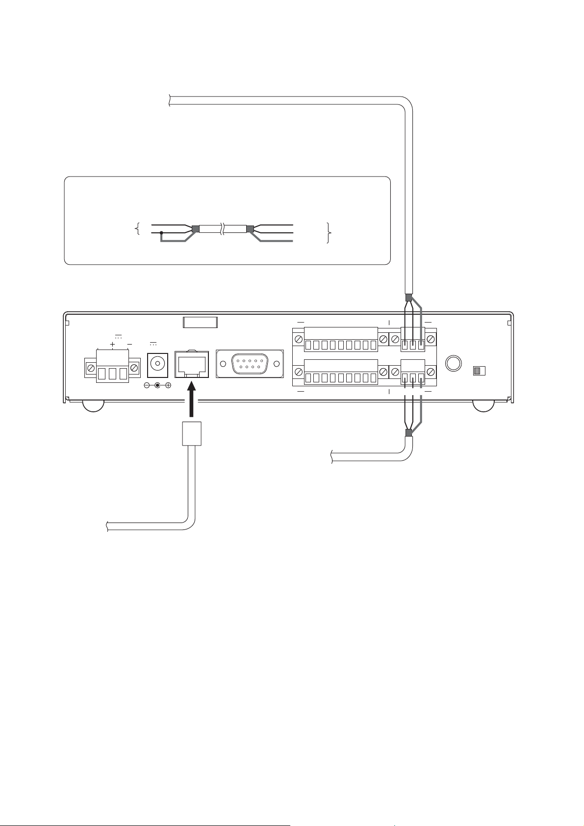
1.1.2. When using the AC adapter
Connect the AC adapter* to the unit's AC adapter terminal. Pinch the cord with a clamp and securely fix it.
* Use the AC adapter AD-246 (optional) or the equivalent. As for the usable adapter, consult your TOA dealer.
Note
When noise interference affects voice output, connecting
the unit's Earth terminal (FG terminal for the NX-100,
SIGNAL GND terminal for the NX-100S) to the ground
terminal of the connected amplifier or mixer may improve
the condition.
1.1.3. When simultaneously using the 24V DC power supply and the AC adapter
When both the 24 V DC power supply and the AC adapter are simultaneously used, the AC adapter takes
precedence. However, should power from the AC adapter be interrupted due to a power failure, etc., the
power supply will automatically switch over to the unit's 24 V DC power source. Connecting a battery directly
to the DC INPUT terminal also permits it to be used as backup power supply during a power failure.
NX-100 only
Mount the ferrite clamp (supplied with the NX-100S) on the cable in a way that the cable is looped
one turn as illustrated. (This countermeasure is for complying with the CE marking requirements.)
FG
DC INPUT
24V
200mA
AC ADAPTER
DC INPUT
24V 200mA
10/100M
To 24V DC power source
SIGNAL
GND
DC
INPUT
24V 200mA
AC adapter
Cord clamp
10/100M
This figure represents the NX-100S.
Ferrite clamp SFC-8 (supplied with the NX-100S only)
2-3
Chapter 2: UNIT AND SOFTWARE INSTALLATIONS
1.2. Terminal Connections
Note
Refer to p. 2-5, CONNECTIONS TO TERMINAL PLUGS, for audio terminal connection procedures.
To mixer, amplifier, etc.
• Audio Output Terminal Connections
Connect the mixer, amplifier, etc. using 2-core
shielded cable.
When the connected unit has an unbalanced input, make the connections
as follows:
Connected Unit
H
E
Shield Shield
This figure represents the NX-100.
200mA
AC ADAPTER
DC INPUT
24V 200mA
10/100M
FG
DC INPUT
24V
Hot (H)
Cold (C)
Earth (E)
CONTACT OUTPUT
RS-232C
CONTACT INPUT
To microphone or
other sound sources
NX-100/100S
76
8C54321
76
C854321
H C E
HCE
H C E
HCE
AUDIO OUTPUT
INPUT
VOLUME
LINE
AUDIO INPUT
MIC
• Audio Input Terminal Connections
Connect the microphone or other sound
sources using 2-core shielded cable.
• Network Connections
The NX-100/100S automatically distinguishes between 10BASE-T and 100BASE-TX networks, and
establishes a connection. For this connection, use a "straight" UTP Category 5 LAN (Ethernet) cable
fitted with an RJ-45 connector.
Tip
It is recommended that the unit be connected to network equipment capable of performing full-duplex
communications.
2-4
Chapter 2: UNIT AND SOFTWARE INSTALLATIONS
Tips
• Refer to p. 2-5, CONNECTIONS TO TERMINAL PLUGS, for control terminal connection procedures.
• When not using the RS-232C interface, place the supplied RS-232C cover over the terminal to protect it
against dust.
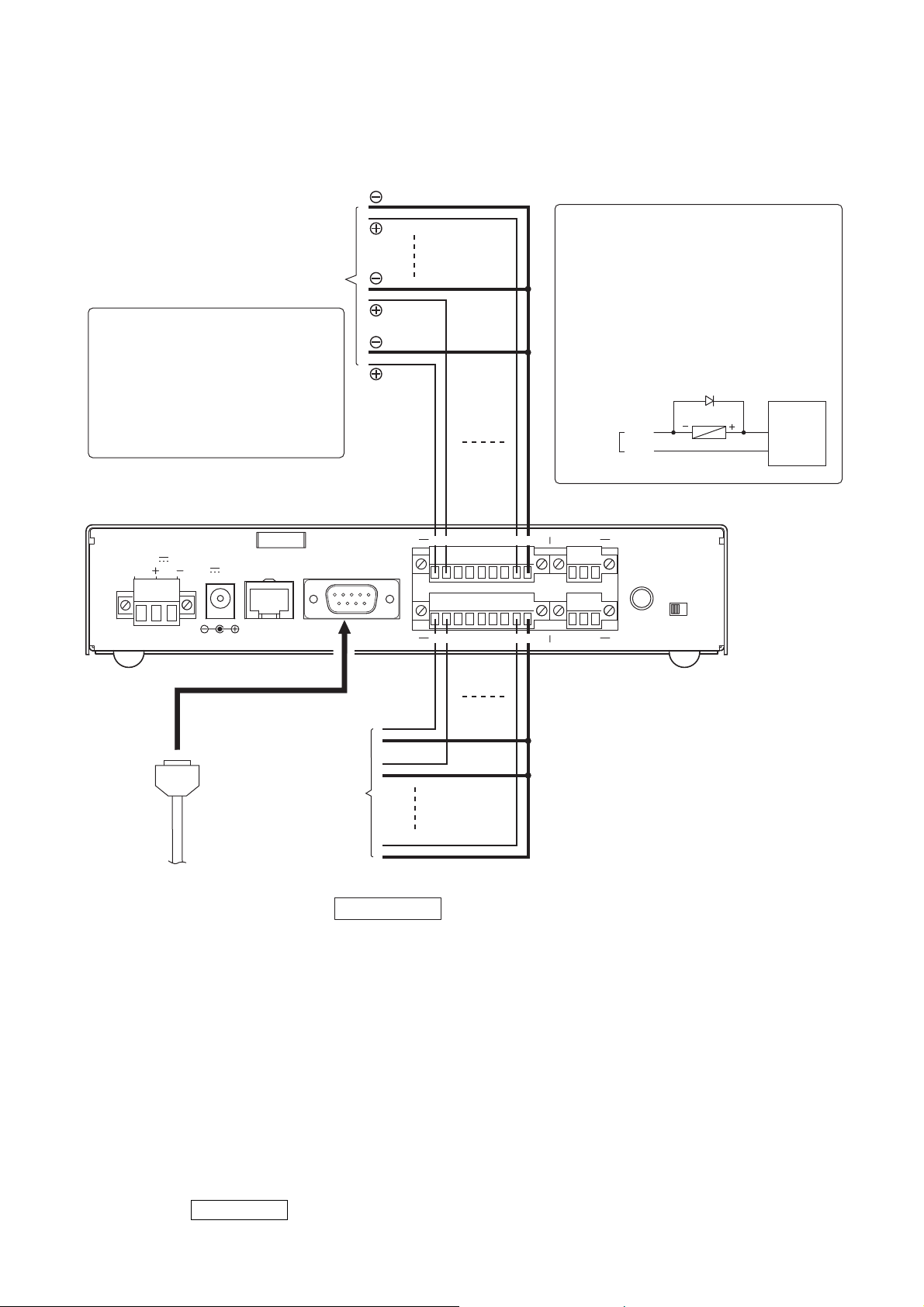
NX-100 only
• Control Output Terminal Connections
Connect the control input terminals of all other
connected units using 2 control lines.
To other unit's control input
Caution
Be sure to connect only these
control lines to other unit's control
input terminals.
Connecting in parallel with control
lines from other equipment may
cause the unit to malfunction.
This figure represents the NX-100.
CONTACT OUTPUT
RS-232C
FG
DC INPUT
24V
200mA
AC ADAPTER
DC INPUT
24V 200mA
10/100M
[Control Output Specifications]
Open collector output
Withstand voltage: 30 V DC
Control current: 50 mA maximum
Pulse width: 1 s (when in Latch mode)
Note
To control a power distributor or PA
amplifier mounted in the same rack
as the unit using the unit's control
output terminals, provide an external
relay and power supply as shown
below to perform control with the
relay contacts.
Diode
LINE
Relay
MIC
CONTACT
OUTPUT
76
8C54321
768C54231
HCE
1 – 8
C
AUDIO OUTPUT
INPUT
VOLUME
External
power supply
+24 V DC
GND
CONTACT INPUT
To other unit's
control output
• RS-232C Interface Connections
NX-100 only
The NX-100 can be used to control such RS-232C
components as DTE and DCE components over a
network.
Use a "straight" cable fitted with a 9-pin D-sub
connector when connecting to DTE components
such as PCs.
Use a "cross" cable fitted with a 9-pin D-sub
connector for connecting to DCE components such
as modems.
76
C854321
76C854321
HCE
AUDIO INPUT
[Control Input Specifications]
No-voltage "make" contact input
Short circuit current: 10 mA
Open voltage: 12 V
Pulse width: Over 50 ms
• Connections to the Control Input Terminal
Connect the control output terminals of all other
connected units using 2 control lines.

2-5
Chapter 2: UNIT AND SOFTWARE INSTALLATIONS
2. CONNECTIONS TO TERMINAL PLUGS
Wire the removable terminal plugs for power input (NX-100 only), audio input and output, and control input
and output as follows:
[Cable size and width to strip]
Caution
Avoid soldering stranded or shielded cable, as contact resistance may increase when the cable is tightened
and the solder is crushed, possibly resulting in an excessive rise in joint temperatures.
[Wiring procedure]
Step 1. Wiring the supplied removable
terminal plug.
1-1. Loosen the terminal screws to insert
the wire.
1-2. Tighten the terminal screws.
Ensure that the wire does not break
free when pulled. If the wire does pull
free, repeat the connection procedure
from the start.
Step 2. Insert the wired terminal plug into the
corresponding terminal block in the
unit's rear panel.
Step 3. Tighten the fixing screws.
Cautions
• Do not reverse Steps 1 and 2. Poor contact may result if force is applied to the unit's internal circuit board
pins while the terminal screws are being tightened.
• Use an appropriate type screwdriver for terminal plug wiring.
NX-100 only
Application Size Width to Strip
Solid cable and stranded cable
For power supply terminal
AWG24 – 12
NX-100 only
Shielded cable
For audio terminal
AWG28 – 16
For control terminal
7 mm
7 mm
15 mm
Removable
terminal plug
1
Tighten
This figure represents the NX-100.
Tighten
H CE
AUDIO OUTPUT
2
INPUT
VOLUME
H
C E
AUDIO INPUT
3
NX-100 rear panel
MICLINE
2-6
Chapter 2: UNIT AND SOFTWARE INSTALLATIONS
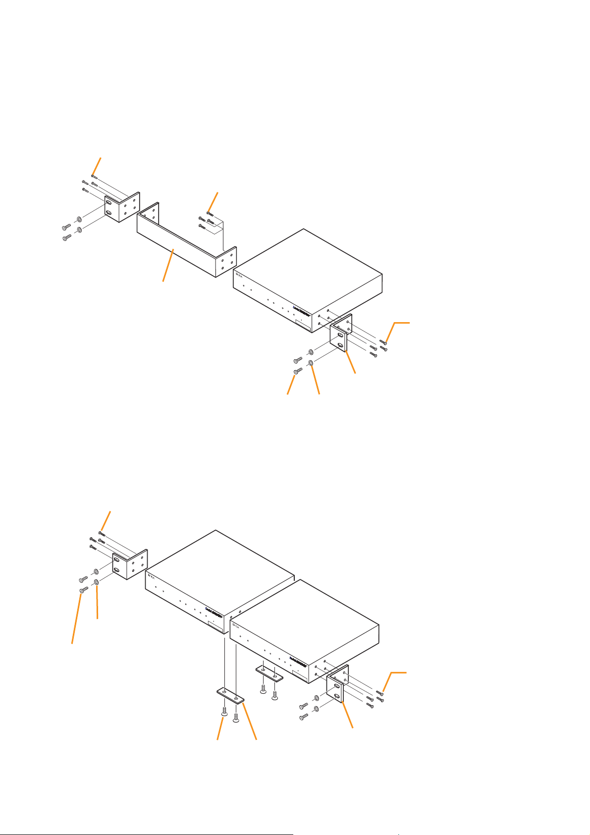
3. RACK MOUNTING
Use the optional mounting hardware set when installing the unit in an equipment rack. Be sure to remove the
rubber feet located on the unit's bottom surface before mounting.
• Use the optional MB-15B-BK hardware set when mounting a single unit.
• Use the optional MB-15B-J hardware set when mounting 2 units.
*1Component parts of MB-15B-BK
*
2
Note
Never use the screws supplied with the
MB-15B-BK to mount the bracket.
The screws supplied with the MB-15B-BK
are so long as to damage the internal
parts, possibly causing the unit to fail.
*
1
Component parts of MB-15B-J
*
2
Note
Never use the screws supplied with the
MB-15B-J to mount the bracket.
The screws supplied with the MB-15B-J
are so long as to damage the internal
parts, possibly causing the unit to fail.
3 x 4 tapping screw*
Blank bracket*
1
5 x 12 rack mounting screw*
1
M3 x 10 machine screw*
2
(supplied with NX-100/100S)
NETWORK AUDIO ADAPTER NX-100S
LNK/ACT FD/COL SIGNAL
NX-100/100S
INPUT
PEAK
STATUS
ERROR
RUN
RESET
00-05-F9-FF-80-81
M3 x 10 machine screw*
2
(supplied with NX-100/100S)
Rack mounting bracket*
1
Fiber washer (for M5)*
1
1
NX-100/100S
INPUT
SIGNAL
PEAK STATUS
ERROR
RUN
1
1
2
RESET
00-05-F9-FF-80-81
NETWORK AUDIO ADAPTER NX-100S
LNK/A
CT
FD/COL
NX-100/100S
INPUT
SI
GNAL
PEAK
STATUS
ERROR
RUN
00-05-F9-FF-80-81
RESET
Rack mounting bracket*
1
Coupler*
1
M3 x 10 machine screw*
(supplied with NX-100/100S)
NETWORK AUDIO ADAPTER NX-100S
LNK/ACT FD/COL
Fiber washer (for M5)*
5 x 12 rack mounting screw*
M3 x 6 oval head screw*
M3 x 10 machine screw*
(supplied with NX-100/100S)
1
2

2-7
Chapter 2: UNIT AND SOFTWARE INSTALLATIONS
4. MAC ADDRESSES AND INSTALLATION LOCATIONS
When making the unit's network settings, the unit's MAC address* must have a clear association with its
corresponding installation location. Be sure to record the relationship during installation to facilitate later
network settings.
* A 12-digit hexadecimal address number peculiar to and assigned to the network-connected unit.
This figure represents the NX-100.
NETWORK AUDIO ADAPTER NX-100
LNK/ACT FD/COL STATUS ERROR RUN
RESET
00-05-F9-FF-80-81
MAC address
2-8
Chapter 2: UNIT AND SOFTWARE INSTALLATIONS
5. SOFTWARE INSTALLATION
5.1. System Conditions
The following minimum PC (personal computer) specifications are required in order to correctly operate the
unit's software program.
Notes
• Windows is a trademark of Microsoft Corporation.
• Pentium is a trademark of Intel Corporation.
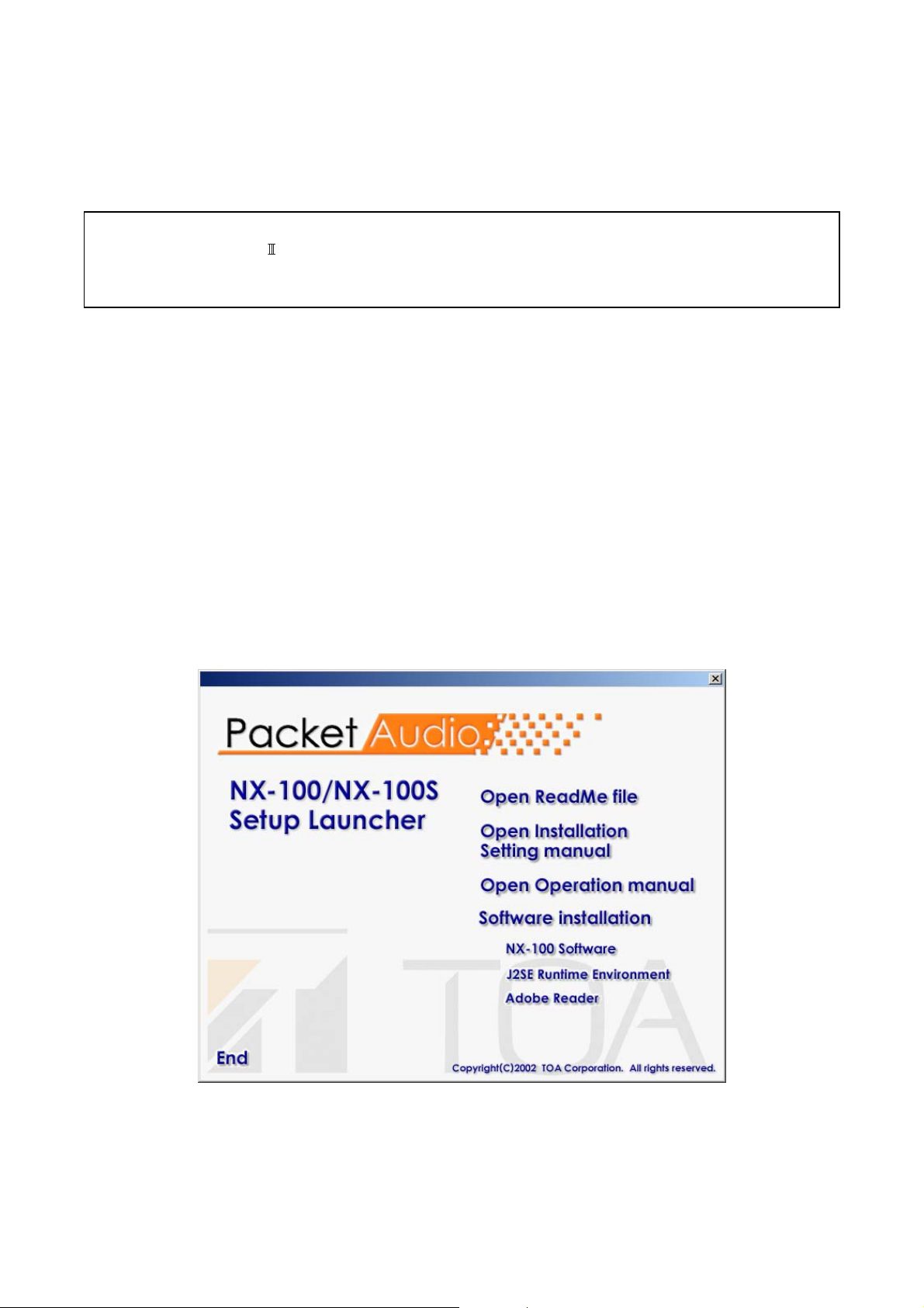
5.2. Activating the Setup Launcher
The Setup Launcher is automatically started when the supplied CD-ROM is inserted into the PC's drive.
Note
The Setup Launcher will not be automatically activated when the CD-ROM is inserted if the PC's CD drive is
not compatible with an auto-run function. In such cases, execute the "Setup Launcher" file below using
"Explorer" or "My Computer" or select Start → Run on the taskbar to enter the command below:
<Drive in which a CD is inserted> \Autorun.exe
[Example] When a CD is inserted into drive e → e:\Autorun.exe
• OS: Windows 2000/XP
• CPU: Pentium 800 MHz or greater
• RAM: 256 MB or greater
• Disk Space: 40 MB or greater
2-9
Chapter 2: UNIT AND SOFTWARE INSTALLATIONS
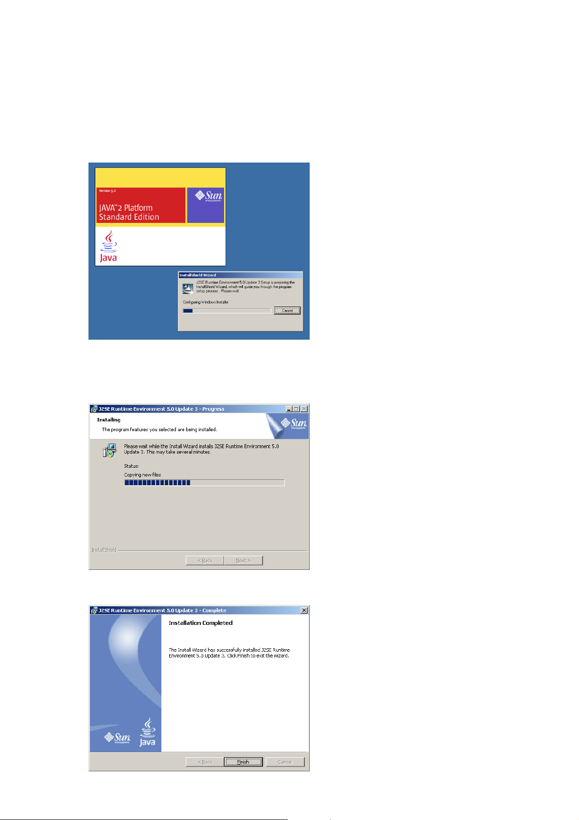
5.3. Installing Java Runtime Environment
The following procedures do not need to be carried out if J2SE Runtime Environment,5.0 Update 3 has
already been installed in the PC.
Step 1. Quit other activated applications before installation.
Step 2. Click "J2SE Runtime Environment 5.0 Update 3" of the Setup Launcher.
The installer will be activated.
Step 3. Select "I accept the terms in the license agreement." and "Typical," then click the Next button as
instructed by the screen.
Installation will begin and the progress status displayed.
The "Installation Completed" indication will be displayed upon installation completion.

2-10
Chapter 2: UNIT AND SOFTWARE INSTALLATIONS
Tip
Check the correct Runtime installation or version number from "Control Panel."
Installation completion icon

2-11
Chapter 2: UNIT AND SOFTWARE INSTALLATIONS
5.4. Installing the NX-100 Software
The NX-100 software consists of the following 2 programs.
• NX-100 Setup Program (Installation Setting)
Enables integrated setting of the NX-100 and NX-100S from the PC.
• NX-100 Operation Program
Enables integrated setting of the NX-100 and NX-100S from the PC for broadcast activation.
Install this software program to operate the unit from the PC.
5.4.1. Installation procedures
Step 1. Click "NX-100 Software" in the Setup Launcher.
The installer will be activated.

2-12
Chapter 2: UNIT AND SOFTWARE INSTALLATIONS
Step 3. When installing in a different folder from the one displayed, press the Change button to select the
desired folder. Press the Next button if the currently displayed folder is correct.
The "Setup Type" screen will be displayed.
Step 2. Click the Next button.
The screen "Destination Folder" will be displayed.

2-13
Chapter 2: UNIT AND SOFTWARE INSTALLATIONS
Step 4. Select the NX-100 software program to install, then press the Next button.
Tip
When installing simultaneously the NX-100 Setup Program (Installation Setting) and Operation
Program, select "NX-100 Software Custom-Setup."
[If something other than NX-100 Software Custom-Setup is selected]
Installation will begin.
[If NX-100 Software Custom-Setup is selected]
The screen for selecting the software program to install in Custom Setup mode is displayed.
4-1. Click the icon to select software program.
The popup menu for selecting the installation method will be displayed.
4-2. Select "This feature will be installed on local hard drive." for the software program(s) to be installed,
and "This feature will not be available." for software program(s) not to be installed.
4-3. Press the Next button.
Installation will begin.
2-14
Chapter 2: UNIT AND SOFTWARE INSTALLATIONS
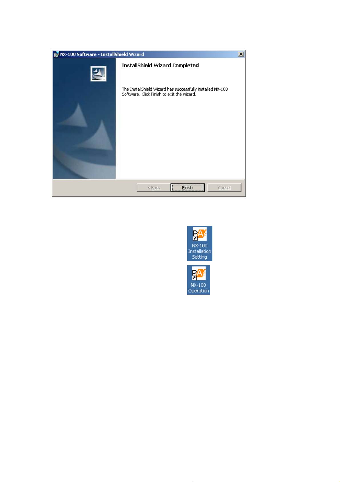
Step 5. Press the Finish button when the indication "InstallShield Wizard Completed" is displayed after
installation completion.
Tip
An icon for the installed NX-100 software program is created on the desktop.
NX-100 Setup Program (Installation Setting):
NX-100 Operation Program:
5.4.2. Update information
• The latest versions of the following software and manuals are open to the public on the Toa's download site
http://www.toa-products.com/international/: NX-100 firmware, NX-100 software (Setup program and
Operation program), and Instruction manuals (Installation setup manual and Operations manual). Please
download them from the above web site.
• To confirm the NX-100 software version, use the Help menu of the software.
• The version of each instruction manual is in the lower right corner on the last page expressed in a yearmonth format. Example: "200406" represents 2004, June.

2-15
Chapter 2: UNIT AND SOFTWARE INSTALLATIONS
5.4.3. Installation folder configuration
The installed software program is stored by default in C:\Program Files\TOA\NX-100. The installation folder is
configured as follows. (However, the unit setting file is only created after having been set by the setup
program, and the unit operation log is created after the NX-100/100S unit's first actual operation.)
Data in the data folder are commonly used by both the Setup Program and the Operation Program. The Setup
Program and the Operation Program always operate based on the unit setting files in the data folder.
Manually opening or saving these files cannot be performed.
Do not change the configuration or name of the file or folder in the installation folder.
When creating other systems or saving backup copies, copy the data folder into other location and save it. (To
reuse, replace the data folder with the one in use.)
5.5. Uninstalling Each Software
Select [Control Panel] → [Add/Remove Programs] to delete.
Installation Folder
nx100_control.jar (Operation Program)
nx100_util.jar (Setup Program - Installation Setting)
packet_audio.jar
data (data folder)
Config (folder to store unit setting files) [IP address].cfg (unit setting file)
Log (folder to store logs)
System.nxc (setup program system file)
panel.nxc (operation program system file)
[IP address].log (unit operation log file)

Chapter 3
SYSTEM SETTINGS
(NX-100 SETUP PROGRAM)

3-2
Chapter 3: SYSTEM SETTINGS (NX-100 SETUP PROGRAM)
1. GENERAL DESCRIPTION
1.1. What is the NX-100 Setup Program?
This program is used to set all the NX-100 and NX-100S units connected to a LAN. It also provides a simple
display on the PC screen of operating data for multiple NX-100 and NX-100S units connected to a LAN.
Its main features are as follows:
• Scans and displays all NX-100 and NX-100S units connected to a LAN.
• Automatically sets IP addresses without duplication. Permits manual changes as well.
• Permits simultaneous uploading of setting files to two or more NX-100 and NX-100S units.
• Backs up setting files for two or more NX-100 and NX-100S units in a batch.
• Easily and efficiently performs broadcast settings between units.
Note
When setting the unit connected to the Internet, refer to Chapter 4, System Settings (Setting Using Browser).
1.2. About Network Settings
Follow the instructions of the network management personnel before performing network settings for the PC
and connected units. Incorrect settings may adversely influence other units connected to the same network.
1.3. Backing-Up Setting Files
Setting contents, once saved, are saved in the data folder located inside the Setup program's installation
folder (Default path: C:\Program Files\TOA\NX-100) as a unit setting file. If uploaded, these files are stored in
each NX-100 and NX-100S as unit setting files. It is highly recommended that all settings be backed up.
Backing up settings to other locations on the PC hard drive or to external storage devices facilitates
restoration should the NX-100, NX-100S or PC inadvertently fail. To save backup copies, copy the entire data
folder located in the Setup program's installation folder.
Caution
When settings are changed, be sure to update the backup files as well.
1.4. Cautions Concerning Setting Updates
Never restart the NX-100 and NX-100S units nor turn off their power supply while updating* the setting
contents.
* The Status indicator on the unit's front panel flashes during an update.
3-3
Chapter 3: SYSTEM SETTINGS (NX-100 SETUP PROGRAM)
2. SETUP SOFTWARE CONFIGURATION AND SETTING ITEMS
The Installation Setting Program permits settings of all items including unit scanning and network setting. First
set all items using this software at the time of system installation. The following two tools are made available:
[Unit Scanning Tool]
Performs unit scanning and network settings. Using this tool, first scan the NX-100 and NX-100S units
connected to the LAN for the system initial setting.
[System Setting Tool]
Performs settings of unit broadcast, contact, serial bridge, etc. It is possible to create the system setting file
beforehand by entering a unit setting before installation.
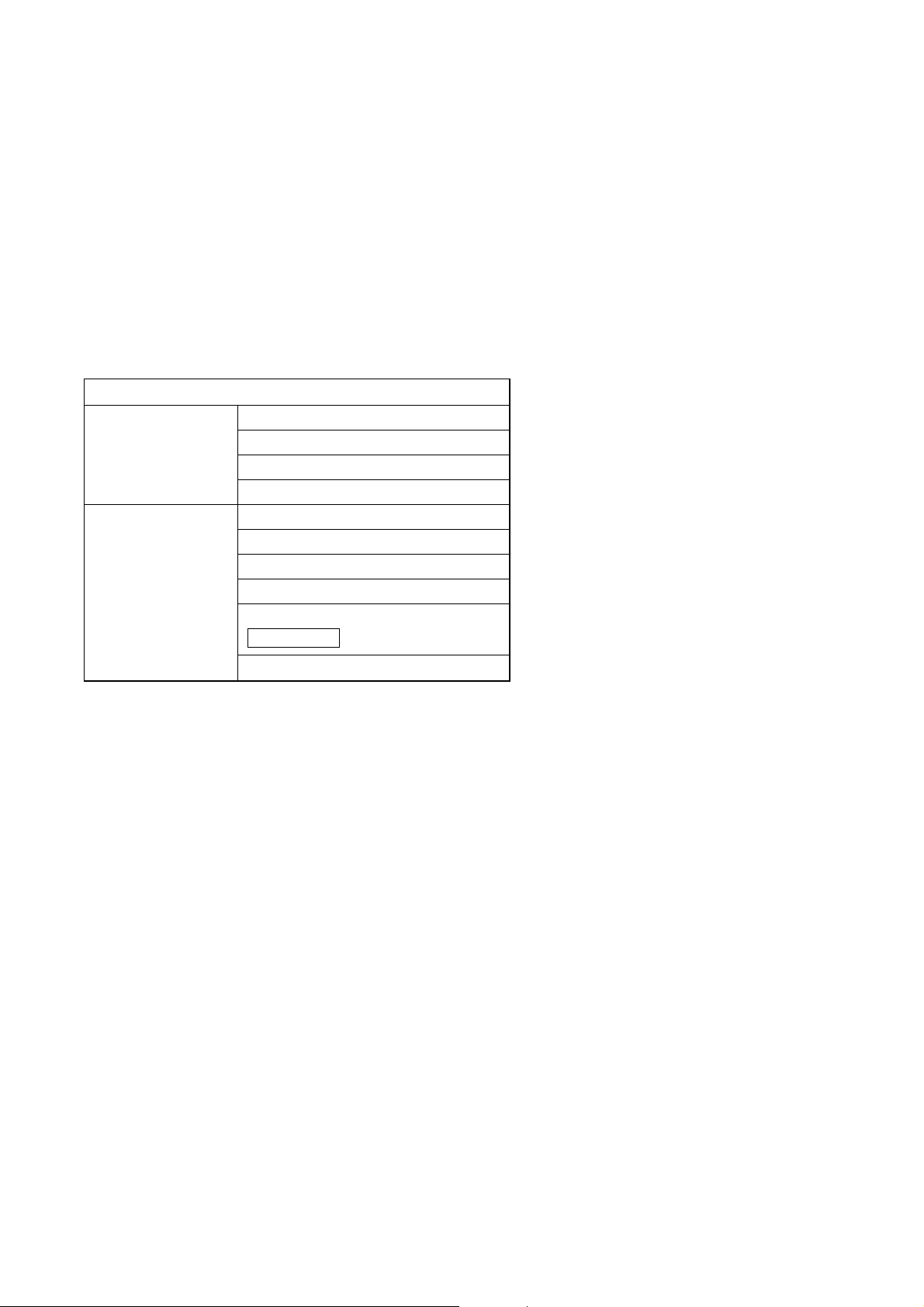
Setting Item
Unit Scanning Tool Unit scanning (See p. 3-10)
IP address (See p. 3-11)
Subnet mask (See p. 3-12)
Default gateway (See p. 3-12)
System Setup Tool Network (See p. 3-16)
Broadcast spec (See p. 3-18)
Broadcast pattern (See p. 3-20)
Contact (See p. 3-23)
Serial bridge (See p. 3-27)
System (See p. 3-29)
NX-100 only
Setting items table

3-4
Chapter 3: SYSTEM SETTINGS (NX-100 SETUP PROGRAM)
3. SETTING PROCEDURE
Pattern 1: Initial On-Site Setup
(1) Unit Scanning (Network Setting)
• After scanning the unit using the Setup program's Unit Scanning Tool, set the IP address, default
gateway, subnet mask, and unit name.
• Upload the network setting data.
• Save the network setting data in unit setting file format ([IP address].cfg).
(2) System Setting
Set non-network items using the System Setting Tool.
Manually add any units that could not be scanned, and enter their IP addresses and unit names.
Set the following items in the order listed:
• System: Set audio I/O unit names.
• Network: Set the port number.
• Broadcast Spec: Perform Broadcast Spec settings based on the network configuration.
Before using this function, confirm the following information with network
management personnel:
· Usable bandwidth
· Whether or not multicast streaming can be used
• Broadcast Pattern: Set the units to be connected in each broadcast pattern when activated by
contact or the Operation program. (This setting not needed for units that will not
be used in broadcast patterns.)
• Contact: Set the broadcast pattern to be activated when a contact is received, and the
contact output for other connected units. Also, set the operation to be
performed when contact output is activated by other units.
• Serial Bridge : Set the units to be connected and their serial ports when using the
serial bridge function.
NX-100 only
(3) Setting Upload
Upload the unit setting file in order to enable the settings set in Step (2) above.

3-5
Chapter 3: SYSTEM SETTINGS (NX-100 SETUP PROGRAM)
Pattern 2: Uploading the programmed system setting file after scanning the
connected units on-site.
(1) System Setting
Using the System Setting Tool, program all the units in the system, and enter their unit names and IP
address numbers.
• System: Set audio I/O unit names.
• Network: Set the port number.
• Broadcast Spec: Perform Broadcast Spec settings based on the network configuration.
Before using this function, confirm the following information with network
management personnel:
· Usable bandwidth
· Whether or not multicast streaming can be used
• Broadcast Pattern: Set the units to be connected in each broadcast pattern when activated by
contact or the Operation program. (This setting not needed for units that will not
be used in broadcast patterns.)
• Contact: Set the broadcast pattern to be activated when a contact is received, and the
contact output for other connected units. Also, set the operation to be
performed when contact output is activated by other units.
• Serial Bridge : Set the units to be connected and their serial ports when using the
serial bridge function.
NX-100 only
(2) Saving Data Files
Save the data folder located in the Setup program's installation folder to the PC's hard disk drive or a
connected external storage device. Also be sure to save backup copies.
(3) Unit Scanning (Network Setting)
• After installing the system's Setup program on-site, copy the contents of the data folder saved in
Step (2) above to the data folder.
• After setting the network using the Unit Scanning Tool, upload the unit setting file using the System
Setting Tool.
Important
When performing settings according to this procedure, the pre-programmed set system setting contents are
erased if [Save in setting file format] is executed using the Unit Scanning Tool. To prevent this, take the
following precautions:
1. After completing settings using the System Setting Tool, copy and save the data folder under a
different name.
If a data folder copy is saved, even when [Save in setting file format] is selected, it is possible to write the
unit setting file into the NX-100 and NX-100S after recopying the previously saved and renamed folder to
the data folder.
2. After performing settings using the Unit Scanning Tool, use the System Setting Tool only after
uploading the settings, but without executing [Save in setting file format].
This prevents the unit setting file in the data folder from being overwritten.

3-6
Chapter 3: SYSTEM SETTINGS (NX-100 SETUP PROGRAM)
4. STARTUP OF INSTALLATION SETTING PROGRAM
Step 1. Either double-click on the Installation Setting Program icon that was created on the desktop during
installation or directly double-click on the application [nx100_util.jar] installed in the Software folder.
The User Authentication dialog will be displayed.
Step 2. Enter the system name and password, then press the OK button.
Note: Both the system name and password are case-sensitive.
The default system name is factory-preset to "NX-100" and the password to "guest."
To change them, refer to
p. 3-31.
When the system name and password are entered correctly, the initial Installation Setting Program
screen is displayed.
Tip
At startup, the Setup program automatically loads data related to unit setting from the data folder.
Step 3. When scanning the unit, click on [Unit Scan (Network Setting)].
Tip
When the settings are saved, a unit setting file is automatically created for each individual IP address
and saved in the data folder. If a unit setting file of the same name already exists in the data folder, it
is overwritten.

3-7
Chapter 3: SYSTEM SETTINGS (NX-100 SETUP PROGRAM)
Step 4. Click on [System Setting] when performing such system settings as broadcast configuration.
Tip
When the settings are saved, a unit setting file is automatically created for each individual IP address
and saved in the data folder. If a unit setting file of the same name already exists in the data folder, it
is overwritten.
Step 5. Click on [Password Change] to change the password.
Step 6. Click on [End] to exit the program.

3-8
Chapter 3: SYSTEM SETTINGS (NX-100 SETUP PROGRAM)
5. UNIT SCANNING TOOL
Scans the units connected to the LAN.
Setting data can only be uploaded into the NX-100S and NX-100 units after each unit's IP address has been
correctly set by way of either the Installation Setting Program's Unit Scanning Tool or a browser.
5.1. Screen Description
Click on [Unit Scan (Network Setting)] on the initial screen.
Shown below is an example of the screen displayed after the units have been scanned.
(1) Scanned unit list
A list showing the units scanned.
(2) MAC address
Displays the MAC addresses of the units
scanned.
Cannot be changed.
(3) Unit type
Displays either type of unit NX-100 or NX-100S.
(4) IP address
Displays the IP addresses of the units scanned.
(5) Subnet mask
Displays the subnet mask to be set for the units
scanned.
(6) Default gateway
Displays the default gateway to be set for the
units scanned.
(7) Web port
Displays the port number of the web server.
(8) Name
Displays the names of the units scanned.
Note
When selecting a unit, tick the leftmost checkbox in the scanned unit list.

3-9
Chapter 3: SYSTEM SETTINGS (NX-100 SETUP PROGRAM)
5.2. Menu
5.2.1. File
Save in setting file format (Ctrl+S): Saves scanned unit data to the PC in unit setting file format ([IP
address].cfg)
Exit: Exits the program.
Important
The [Save in setting file format] function is used to set broadcasts in the system settings after the unit scan is
complete. Selecting [Save in setting file format] writes the setting contents into the data folder. The contents of
the unit setting file include only the IP address, subnet mask, default gateway, unit name, and Web server port
number.
When broadcast contents have previously been set and saved using the System Setting Tool, these earlier
system settings will be erased if [Save in setting file format] is selected.
If system setting has already been performed, take the following measures to prevent erasure of the setting
contents:
1. Upon completion of System Setting Tool settings, copy and save the data folder under a different
name.
If the data folder is copied, the unit setting file can be written into the NX-100 and the NX-100S after
copying the renamed folder to the data folder, even when [Save in setting file format] is selected.
2. After Unit Scanning Tool settings have been performed, use the System Setting Tool after
uploading the settings, but without executing [Save in setting file format].
This prevents the unit setting file in the data folder from being overwritten.
5.2.2. Scan
Unit scan: Scans the units connected to the LAN.
Change settings: Uploads the settings of the selected unit.
IP address: Automatically assigns an IP address and performs related settings.
Auto assignment: Automatically assigns an IP address to the selected unit.
Assignment range setting: Sets the IP address range to be used in automatic IP address assignment.
Subnet mask setting: Sets the same subnet mask to the selected units.
Default gateway setting: Sets the same default gateway to the selected units.
Select all (Ctrl+A): Selects all of the units scanned.

3-10
Chapter 3: SYSTEM SETTINGS (NX-100 SETUP PROGRAM)
5.2.3. Help
Help: Displays help contents.
Version data: Indicates the version of the program in use.
5.3. Buttons
(1)
(2)
(1) Unit scan button: Scans all the units on the LAN.
(2) Setting upload button: Writes the IP address, subnet mask, default gateway, and name into the selected
units.
5.4. Scanning Units
Scans each unit connected to the LAN.
Step 1. Connect NX-100 and NX-100S units to the network and turn on each power.
The LNK/ACT Indicator will light.
Step 2. Either press the Unit Scan Button or select [Scan] → [Unit scan].
The MAC address, IP address, subnet mask, default gateway, and unit name of the NX-100 and
NX-100S connected to the LAN will be displayed.
Default values are factory-preset as follows:
IP address: 192.168.1.1
Subnet mask: 255.255.255.0
Default gateway: 0.0.0.0
Name: NX-100S or NX-100
Caution
Units can only be scanned within the effective broadcast range. (See p. 6-3.)
For the units that cannot be scanned, manually add only the units connected to the LAN with the System
Setting Tool.

3-11
Chapter 3: SYSTEM SETTINGS (NX-100 SETUP PROGRAM)
5.5. Changing the Unit Setting Values
Change the unit's setting values individually.
Step 1. Double-click on the desired cell.
Data can be entered.
Step 2. Enter a new value.
Step 3. Press the Enter key or click on another cell.
Step 4. After editing completion, press the Upload Button .
Caution
Since the NX-100 and NX-100S units are automatically reset after uploading, any broadcasts currently in
progress are stopped.
5.6. Automatic IP Address Assignment
Set the IP address for the unit scanned.
Besides the "Changing the Unit Setting Values" method described in the previous item, there is another
method for automatically assigning addresses by limiting the IP address setting range.
Step 1. Select the unit to which the address is assigned by ticking its selection checkbox.
To assign the same address to all units, select [Scan] → [Select all].
Step 2. Select [Scan] → [IP address] → [Assignment range setting] to set the usable IP address range.
Setting the range permits the selection of [Scan] → [IP address] → [Automatic assignment].
Step 3. Select [Scan] → [IP address] → [Automatic assignment].
The IP addresses are automatically assigned without duplicating.

3-12
Chapter 3: SYSTEM SETTINGS (NX-100 SETUP PROGRAM)
5.7. Subnet Mask and Default Gateway Settings
The same subnet mask and default gateway numbers can be set for all selected units.
Step 1. Tick the selection checkbox to select the unit.
To select all units, select [Scan] → [Select all].
Step 2. Set the subnet mask.
2-1. Select [Scan] → [Subnet mask setting].
2-2. A dialog will be displayed. Enter the setting value and click on the OK button.
Step 3. Set the default gateway.
2-1. Select [Scan] → [Default gateway setting].
2-2. A dialog will be displayed. Enter the setting value and click on the OK button.

3-13
Chapter 3: SYSTEM SETTINGS (NX-100 SETUP PROGRAM)
6. SYSTEM SETTING TOOL
Setting data can only be updated after the unit's IP address has been correctly set by way of either the
Installation Setting Program's Unit Scanning Tool or a browser.
6.1. Screen Description
Clicking on [System Setting] on the Installation Setting Program's initial screen displays the following window.
If the unit to be set is selected, its currently set contents are displayed in the right-side setting form.
(1) Name
Displays the unit names programmed into the system.
(2) IP address
Displays the unit IP addresses programmed into the system.
(3) Web server port
Displays the port number of the web server.
(4) Unit type
Displays either type of unit NX-100 or NX-100S.

3-14
Chapter 3: SYSTEM SETTINGS (NX-100 SETUP PROGRAM)
6.2. Menu
6.2.1. File
Save to file (Ctrl+S): Overwrites and saves the system setting file.
Reopen file (Ctrl+O): Rereads the saved system setting file.
Log file download: Saves the log of all NX-100 and NX-100S operations programmed into the system.
Exit: Exits the program.
6.2.2. Edit
Add
NX-100:Adds the selected NX-100 to the list (edit screen).
NX-100S:Adds the selected NX-100S to the list (edit screen).
Delete: Deletes the selected NX-100 or NX-100S from the list (edit screen).
Clear: Deletes all NX-100 and NX-100S units from the list (edit screen).
6.2.3. Setting
Upload (Ctrl+U): Writes the settings currently being edited into the NX-100 and NX-100S.
Download (Ctrl+D): Downloads the settings from the NX-100 and NX-100S, and displays them on the edit
screen. (Not saved.)
Firmware update: Updates the NX-100 and NX-100S firmware.
6.2.4. Help
Help: Displays help contents.
Version data: Verifies the version number of the NX-100 Setup program.

3-15
Chapter 3: SYSTEM SETTINGS (NX-100 SETUP PROGRAM)
6.2.5. Buttons
(1) Save button: Saves and overwrites the system setting file.
(2) NX-100 Add button: Adds NX-100 units to the network list (edit screen).
(3) NX-100S Add button: Adds NX-100S units to the network list (edit screen).
(4) Delete button: Deletes NX-100 and NX-100S units from the network list (edit screen).
(5) Upload button: Writes the currently edited settings into the NX-100 and NX-100S.
(6) Download button: Downloads NX-100 and NX-100S settings and displays them on the edit screen.
(Not saved.)
(1) (2) (3) (4) (5) (6)

3-16
Chapter 3: SYSTEM SETTINGS (NX-100 SETUP PROGRAM)
6.3. Network Setting
Step 1. Click on the [Network] tab of the System Setting Tool.
The setting screen will be displayed.
Step 2. Set each item.
(1) IP address
Enter the unit's IP address. After the IP address is set with the Unit Scanning Tool, the assigned IP
address is indicated when the unit setting file is loaded into the PC.
(2) TCP port number assignment
Designate the web server port number and the base number of the other TCP port. The port number can
be set within the range of 1 – 65535.
[Web server]
Enter the web server port number. Its default is "80."

3-17
Chapter 3: SYSTEM SETTINGS (NX-100 SETUP PROGRAM)
[Start port No.]
Enter the base number of the TCP port (other than web server, which is used by the unit). The default is
"5000." Enter the number from within the range of 1 – 65532.
The TCP ports are assigned as follows:
(3) UDP port number assignment
Designate the base port number to be used by UDP.
[Start port No.]
Enter the base UDP port number to be used by the unit. The default is "5000." Enter an even number from
within the range of 1 – 65526.
The UDP ports are assigned as follows:
Caution
Since UDP port No. 15000 is used by the unit, numbers between 14990 and 15000 cannot be used.
Por t
Web server
Broadcast control
PC control
Contact bridge
Serial bridge
Por t
Streaming
Error correction
Resend
Protocol
TCP
TCP
TCP
TCP
TCP
Protocol
UDP
UDP
UDP
Start port No. + 0
Start port No. + 2
Start port No. + 4
Por t No.
Web server
Start port No. + 0
Start port No. + 1
Start port No. + 2
Start port No. + 3
Por t No.
Default
80
5000
5001
5002
5003
Default
5000
5002
5004
Serial bridge
Fs* correction
* Sampling frequency
UDP
UDP
Start port No. + 6
Start port No. + 7
5006
5007

3-18
Chapter 3: SYSTEM SETTINGS (NX-100 SETUP PROGRAM)
6.4. Broadcast Spec Setting
Step 1. Click on the Broadcast Spec tab of the System Setting Tool.
The setting screen will be displayed.
Step 2. Select the usable bandwidth at Navigator.
Selection of the usable bandwidth automatically sets recommended values except those related to
Multicast. If no problems are foreseen, perform the setting as is, without changing this value.
Note
For bandwidth and multicast streaming, consult with on-site network management personnel.
Step 3. Set each item while referring to the bandwidth and delay time indicated in the Information area
located at the bottom of the screen.
Caution
Broadcasts are interrupted when the set bandwidth is displayed in red in the Information area. (The
bandwidth is indicated in red whenever this setting exceeds the per-stream usable bandwidth.)
(1) Sampling frequency [kHz]
Select a sampling frequency for both transmission and reception from [8], [16], and [32] kHz. Sound
quality improves with higher sampling frequencies, however this makes the usable bandwidth wider.
Caution
Local broadcasts are disabled if a transmission sampling frequency of [32] kHz is selected (refer to
broadcasting direction in "the Broadcast Pattern Setting" on p. 3-20).
3-19
Chapter 3: SYSTEM SETTINGS (NX-100 SETUP PROGRAM)
(2) Packet size
Select the size of audio packet.
The packet size cannot be changed when [Resend] is selected in the Packet loss recovery item. Smaller
packet sizes result in a wider bandwidth, however delay times become shorter.
(3) Compression
Select [Yes] or [No]. Audio signal compression narrows the bandwidth. To narrow the bandwidth of the
network, it is highly recommended that compression be enabled.
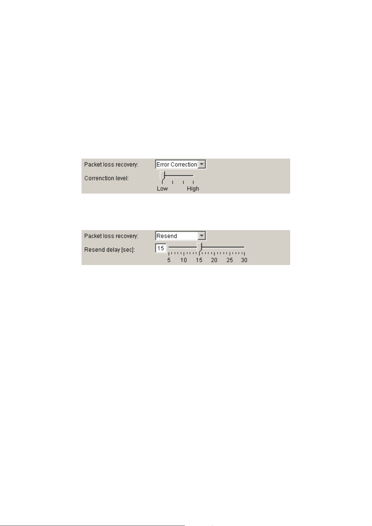
(4) Packet loss recovery
Selects one of three recovery methods used when an audio packet is lost: [Standard], [Error Correction],
and [Resend]. Refer to p. 6-4 for details regarding each recovery method.
[If "Error Correction" is selected]
A scale for setting the correction level appears. Higher settings increase correction capability, however
delay times are also made longer.
[If "Resend" is selected]
A scale for setting delay times appears. Longer delay times increase correction capability.
(5) Enable multicast and Multicast address
Set whether or not to use multicast for broadcasts. Ticking the [Enable multicast] checkbox makes it
possible to enter the multicast address. The effective address range is from (225.0.0.0) to
(238.255.255.255).
Note
Be sure to consult with network management personnel before performing this setting.

3-20
Chapter 3: SYSTEM SETTINGS (NX-100 SETUP PROGRAM)
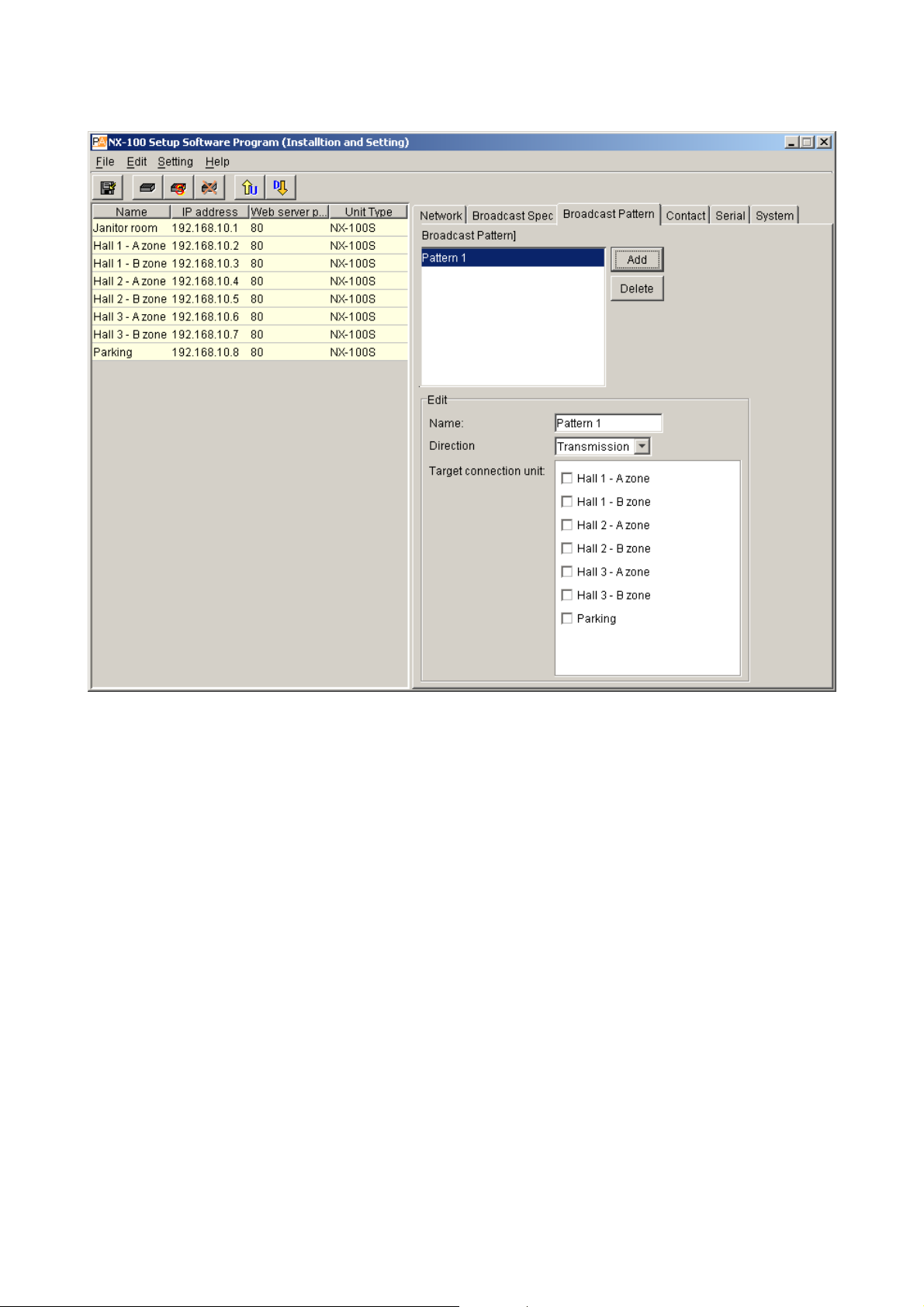
6.5. Broadcast Pattern Setting
6.5.1. Setting new broadcast patterns
Step 1. Click on the [Broadcast Pattern] tab of the System Setting Tool.
The setting screen will be displayed.
3-21
Chapter 3: SYSTEM SETTINGS (NX-100 SETUP PROGRAM)
Step 2. Press the Add button.
The edit area becomes available for editing. Up to 20 patters can be set for each unit.
Step 3. Enter a broadcast pattern name.
Caution
Avoid assigning a name already programmed.
Step 4. Select the broadcasting direction from [Transmission], [Reception], and [Local].
Transmission: Transmits broadcast signals to the connected NX-100 and NX-100S units.
Reception: Receives broadcast signals from the connected NX-100 and NX-100S units.
Local: Makes broadcasts from the Audio Input of the NX-100 or NX-100S unit to its Audio
Output.
Selecting [Transmission] or [Reception] permits selection of the connected unit.
Caution
[Local] broadcasts cannot be made when the transmission sampling frequency is set to 32 kHz in the
Broadcast Spec setting.
Step 5. Select the connected unit from the displayed list (when [Transmission] or [Reception] is selected)
Cautions
• Only those units connected to the LAN can be selected.
• Only one location can be selected when the multicast function is not used. (Also one location for
reception.)
• Only units designated for multicast streaming can be group-selected.

3-22
Chapter 3: SYSTEM SETTINGS (NX-100 SETUP PROGRAM)
6.5.2. Editing broadcast patterns
Step 1. Click on the [Broadcast Pattern] tab of the System Setting Tool.
The setting screen will be displayed.
Step 2. Click on the broadcast pattern to be edited.
The setting contents are displayed in the edit area, allowing editing.
Tip
To delete a previously programmed broadcast pattern, click on the broadcast pattern to be deleted,
then press the Delete button.
Step 3. Re-enter or reselect the section to be changed.

3-23
Chapter 3: SYSTEM SETTINGS (NX-100 SETUP PROGRAM)
6.6. Contact Setting
6.6.1. Contact input setting
Step 1. Click on the [Contact] tab of the System Setting Tool.
Step 2. Click on the selection button for the contact input channel number.
The setting contents will be displayed.
Step 3. Tick the [Enable contact] checkbox.
The setting contents can be edited.

3-24
Chapter 3: SYSTEM SETTINGS (NX-100 SETUP PROGRAM)
Step 4. Set the type to [Momentary] or [Latch].
Momentary: The designated broadcast pattern or other unit's contact output is activated during the
interval that input is ON. Activation stops while the input is OFF.
Latch: The designated broadcast pattern or other unit's contact output is activated when the
input is turned ON, and the activation mode continues even if the input is turned OFF.
Activation stops when the input is turned ON again.
on
Step 5. Set Polarity to [Make] or [Break].
Make: ON when the contact is closed.
Break: ON when the contact is opened.
Step 6. A list of the programmed broadcast patterns is displayed in the [Broadcast pattern] screen. Tick the
checkbox to select the pattern.
Cautions
• Broadcasts cannot be made if the set frequency band exceeds the usable bandwidth.
• Up to 4 broadcast patterns can be selected for transmission, and 1 pattern for reception. (Only 1
pattern for multicast streaming.)
• When no broadcast pattern is displayed, no broadcast patterns are programmed. In such cases,
create new patterns on the Broadcast Pattern setting tab screen.
Step 7. Click to select the connected unit from the [Contact bridge unit] list.
Cautions
• Only those units connected to the LAN can be selected.
• Up to 64 locations can be selected.
• Momentary
ON
Make
Contact input
Break
Contact input
ON
Broadcast and
contact data
• Latch
Broadcast and
contact data
Make
Contact input
Break
Contact input
ON
ON
ON
ON
ActivationStop
50 ms or more
50 ms or more
Activati
ON
ON
Stop
ON
ON

3-25
Chapter 3: SYSTEM SETTINGS (NX-100 SETUP PROGRAM)
6.6.2. Contact output setting
Step 1. Click on the [Contact] tab of the System Setting Tool.
Step 2. Click on the selection button for contact output channel numbers.
The setting contents will be displayed.
Step 3. Tick the checkbox for [Enable contact].
The setting contents can be edited.
Step 4. Select Mode from [Standard], [STATUS Output], and [ERROR Output].
Standard: Provides output by way of control from a PC or contact inputs of other units or
original unit.
STATUS Output: Provides contact output synchronizing with the unit's STATUS indicator operation.
ERROR Output: Provides contact output synchronizing with the unit's ERROR indicator operation.
Note: To use the Contact bridge function, select [Standard].

3-26
Chapter 3: SYSTEM SETTINGS (NX-100 SETUP PROGRAM)
Step 5. Set the type to [Momentary] or [Latch].
Momentary: Provides output during the period between receiving an activation request and receiving
a stop request.
Latch: Provides 1 second of output upon receiving an activation request and 1 second of output
upon receiving a stop request.
Note
[Latch] cannot be selected when setting Mode to [STATUS Output] or [ERROR Output].
Caution
The unit's correct operation cannot be ensured if both activation and stop signals
are received during the 1-second output interval.
Step 6. Select Polarity from [Make] or [Break].
Make: ON when the contact is closed.
Break: ON when the contact is opened.
Step 7. Set OFF delay time from [0] – [60] seconds.
Adjust the displayed scale or enter an OFF delay time of 0 – 60 seconds for the duration between
receiving a termination request and actually turning OFF the contact. When in Resend mode (refer to
p. 3-19, Packet loss recovery) and making broadcasts with longer delay times, set the OFF delay time
to correspond to the delay time.
Note
For more information regarding OFF delay times, refer to p. 6-4.
• Momentary
Make
Break
• Latch
Make
Break
Broadcast and
activation data
Contact output
Contact output
Broadcast and
activation data
Contact output
ON
ON
ON
1 s
Activation Stop
Activation Stop
ON
ON
ON
ON
Contact output
1 s
ON
ON
ON

3-27
Chapter 3: SYSTEM SETTINGS (NX-100 SETUP PROGRAM)
6.7. Serial Bridge Setting
Step 1. Click on the [Serial] tab of the System Setting Tool.
Step 2. Tick [Enable serial port].
The setting screen will be displayed, allowing entry of each item.
NX-100 only
Step 3. Set each item.
(1) Protocol
Select the serial bridge communication method.
TCP server: The unit selected on the setting screen functions as a TCP server and carries out
communications.
TCP client: The unit selected on the setting screen functions as a TCP client and carries out
communications. Clicking the radio button permits selection of the connected unit.
UDP: Carries out UDP communications. Clicking the radio button permits selection of the
connected unit.
(2) Target unit
Select the unit to be connected.
Caution
Only units connected to the LAN can be selected.

3-28
Chapter 3: SYSTEM SETTINGS (NX-100 SETUP PROGRAM)
(3) Baud rate
Select [9600], [19200], [38400], [57600] or [115200]
(4) Data length
Set to either [7 bits] or [8 bits].
(5) Parity
Select [Even], [Odd] or [None].
(6) Stop bits
Select [1 bit] or [2 bits].
(7) Flow control
Select the type of flow control.
None: Flow control is not performed.
Xon/Xoff: Performs software flow control.
Hardware: Performs hardware flow control.
(8) Auto cutoff time (minutes)
Set the time interval (timeout duration: 0 – 60 minutes) before the connected unit is automatically
disconnected following the end of the last communication. The connected unit is not disconnected if the
timeout duration is set to [0]. This function is only available for TCP connections.
(9) Transmit/receive raw data
Tick the checkbox when transmitting and receiving raw data. Data with control information to be utilized
between NX-100 units is usually transmitted, but raw data communications are generally carried out
without such control information. However, when communications with other connected units are cut off,
this cannot be detected. Raw data communications are only possible while in TCP connection mode.
Note
Serial bridge function data can be transmitted at every 20 ms intervals or when its data length becomes 1024
bytes within 20 ms. This serial bridge function cannot be used for the equipment that communicate with data
less than 1024 bytes long at intervals shorter than 20 ms.

3-29
Chapter 3: SYSTEM SETTINGS (NX-100 SETUP PROGRAM)
6.8. System Settings
Step 1. Click on the [System] tab of the System Setting Tool.
The setting screen will be displayed.
Step 2. Perform settings for each item.
(1) Unit
Enter the unit name.
(2) Audio input
Enter the name of the audio input unit connected to the unit.
(3) Audio output
Enter the name of the audio output unit connected to the unit.
(4) Firmware version
Indicates the unit's firmware version number.
6.9. Saving the Unit Setting Files
Save the unit setting file to the specified location.*
* The data folder is located in the installation folder (Default path: C:\Program Files\TOA\NX-100) of the setup
program. The save location cannot be manually designated.
Click on the Save button or select [File] → [Save].

3-30
Chapter 3: SYSTEM SETTINGS (NX-100 SETUP PROGRAM)
6.10. Reopening Unit Setting Files
Reopen the saved unit setting files.
The program automatically reads the saved unit setting files at the time of program activation. Whenever a file
has not yet been saved after edit completion, its contents can be reverted back to the previous settings.
Select [File] → [Reopen file].
6.11. Downloading the Operation Logs
Download all NX-100's and NX-100S' operation logs programmed into the system and save them to a
specified location*.
* The data folder is located in the installation folder (Default path: C:\Program Files\TOA\NX-100) of the setup
program. The save location cannot be manually designated.
Select [File] → [Log file download].
6.12. Uploading Unit Setting Files
Upload the currently opened setting file to the NX-100 and NX-100S.
Step 1. Click on the toolbar Save button or select [File] → [Save to file].
The setting file will be saved.
Step 2. Click on the Upload button or select [Setting] → [Upload].
Note
Setting file upload takes some time. Take care to never switch off the unit's power during the upload. (The
Status indicators on the NX-100's and NX-100S' front panels flash during the upload.)
6.13. Downloading Unit Setting Files
Read the currently-connected NX-100's and NX-100S' setting contents into the System Setting Tool.
Click on the Download button or select [Setting] → [Download].
Programmed setting data of the units connected to the system will be displayed.
6.14. Updating Firmware
Update the firmware of all NX-100 and NX-100S units programmed into the system.
Step 1. Select [Setting] → [Firmware update].
Step 2. Select firmware file.
Firmware will be written into all connected NX-100 and NX-100S units.
Note
Take care to never turn off or reset the unit's power during firmware update. (The Status indicator on each
unit's front panel flashes during the update.)
[Update information]
• The latest versions of the following software and manuals are open to the public on the TOA's download site
http://www.toa-products.com/international/: NX-100 firmware, NX-100 software (Setup program and
Operation program), and Instruction manuals (Installation setup manual and Operations manual).
Please download them from the above web site.
• The version of each instruction manual is in the lower right corner on the last page expressed in a yearmonth format. Example: "200406" represents 2004, June.

3-31
Chapter 3: SYSTEM SETTINGS (NX-100 SETUP PROGRAM)
7. CHANGING THE SYSTEM NAME AND PASSWORD
Step 1. In the Installation Setting Program, click on [Password Change] on the initial screen.
In the Management Setting Program, select [Help] → [Version data], and a dialog will then be
displayed. Click on the Change password button.
The Password Change screen will be displayed.
Step 2. Enter a new system name and password.
Use up to 15 alphanumeric characters to enter the system name and password. (They can be set to
blank.)
Enter the password a second time for verification.

Chapter 4
SYSTEM SETTINGS
(SETTING USING BROWSER)

4-2
Chapter 4: SYSTEM SETTINGS (SETTING USING BROWSER)
1. OUTLINE OF SETTING USING BROWSER
Settings can also be changed without requiring installation of the dedicated NX-100 software by individually
connecting to each NX-100/100S using the browser*.
For NX-100/100S units connected by way of the NAT function, such as an access via internet, perform
settings from the browser.
* Browsers that ensure correct NX-100/100S operation:
Microsoft Internet Explorer 6, Internet Explorer 5.5, and Netscape 7
Notes
• Settings cannot be performed if the network is not correctly set. In particular, new units shipped from the
factory may have duplicate default IP addresses or settings that assume the NX-100/100S is not connected
to the same network as the PC.
• Complete network settings before using the NX-100 Installation Setting program. If performing setup by the
browser, disconnect the unit from the network and connect it directly to the PC's LAN port using a cross
cable.
• Should the power be switched off during setting changes, the unit may be damaged.
• Changed settings are enabled after the NX-100/100S is restarted. Be sure to restart the unit whenever
settings are changed. Broadcasts are stopped during unit restart.
2. SETTINGS
Step 1. Start up the browser and enter the URL.
Note
The factory-preset IP address is "192.168.1.1" and web server port No. is "80." When the web server
port No. is "80," the description of the port number that follows the colon [:] can be omitted.
URL Example
http://<IP address>:<Web server port No.> /admin-e.htm http://192.168.1.1/admin-e.htm
The User Authentication dialog will be displayed. (Note that the dialog display may differ depending
on the browser used.)
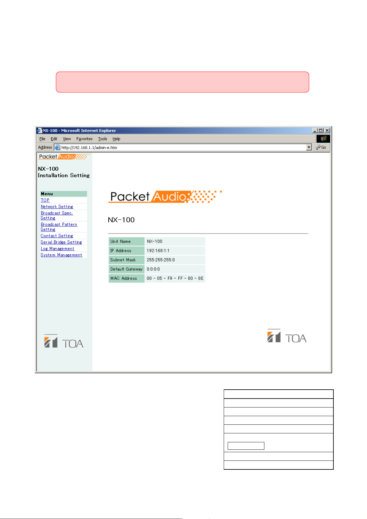
4-3
Chapter 4: SYSTEM SETTINGS (SETTING USING BROWSER)
Step 2. Enter a user name and password, then press the OK button.
Notes
• For the User name, enter the system name preset as default or by change.
• Both the user name and password are case-sensitive.
The default system name is factory-preset to "NX-100" and the password to "guest."
To change them, refer to p. 4-28.
The setting menu window will be displayed if the user name and password are correctly entered.
This figure represents the NX-100.
Step 3. Set each item.
Referring to the corresponding pages, perform each
setting.
Note that serial bridge setting can be performed for the
NX-100 only.
Caution
When displaying each browser setting screen, the screen
is not correctly displayed if the Back or Forward button of
the browser is used. Use the menu on the left-hand side
of the window.
Menu Item
Network setting (See p. 4-4)
Broadcast spec setting (See p. 4-6)
Broadcast pattern setting (See p. 4-9)
Contact setting (See p. 4-13)
Serial bridge setting (See p. 4-18)
Log management (See p. 4-20)
System management (See p. 4-27)
NX-100 only

4-4
Chapter 4: SYSTEM SETTINGS (SETTING USING BROWSER)
3. NETWORK SETTING
Set the NX-100/100S unit's network.
This figure represents the NX-100.
(1) IP Address
Enter the NX-100/100S unit's IP address. (Factory-preset to "192.168.1.1.")
(2) Subnet Mask
Set the mask address. (Factory-preset to "255.255.255.0.")
(3) Default Gateway
Enter the gateway address if the unit is being used outside its assigned subnet.
(Factory-preset to "0.0.0.0.")

4-5
Chapter 4: SYSTEM SETTINGS (SETTING USING BROWSER)
(4) Port No.
Set the start port number to be used by each protocol.
The assigned port numbers are indicated.
[TCP Port No. Assignment]
• Web server
Enter the web server port number
(Range: 1 – 65535; Factory-preset: 80)
• Start port no.
Enter the first TCP port number other than the HTTP, which is used by the NX-100/100S.
(Range: 1 – 65532; Factory-preset: 5000)
[UDP Port No. Assignment]
Designate the first port number to be used by the UDP.
• Start port no.
Enter the first UDP number to be used by the unit.
(Range: EVEN numbers 1 – 65526; Factory-preset: 5000)
Caution
Since UDP port No. 15000 is used by the unit, numbers between 14990 and 15000 cannot be used.
(5) Save button
Updates the NX-100/100S setting file.
Caution
Never restart the unit or turn off the power during updates, or while the STATUS indicator on the front
panel of the NX-100/100S is flashing.

4-6
Chapter 4: SYSTEM SETTINGS (SETTING USING BROWSER)
4. BROADCAST SPEC SETTING
Set the specifications that determine broadcast streaming quality. The NX-100/100S starts its broadcasts
based on this setting.
This figure represents the NX-100.
(1) Navigator
Select the usable bandwidth and type of line, and press the Set button. A recommended values will then
be set. If no problems are foreseen, perform the setting as is, without changing these values.
Note
Be sure to consult with network management personnel regarding bandwidth, type of line, and multicast
streaming.

4-7
Chapter 4: SYSTEM SETTINGS (SETTING USING BROWSER)
(2) Information
Indicates the delay time, bandwidth, and whether or not broadcasts are possible when broadcasts are
made using values selected in the Broadcast Spec settings.
[Delay]
The delay time is the duration until an audio signal received at the NX-100 and NX-100S passes through
the network and is broadcast by other connected NX-100 and NX-100S units.
[Bandwidth]
Indicates the bandwidth for voice streaming over the network. The bandwidth used is indicated in red if the
setting exceeds the usable bandwidth set in the Navigator section.
[Broadcasts possible with this spec]
Broadcasts that are possible with the set Spec are marked with "OK", and those that are not possible are
marked with "NG." The conditions under which broadcasts can be made are as follows:
Transmission only (broadcasts from the original unit to other units):
Broadcast signals can be sent to a connected unit if the transmission bandwidth is within the set
bandwidth.
Reception only (broadcasts from other units to the original unit):
Broadcast signals can be received from a connected unit if the reception bandwidth is within the set
bandwidth.
Local broadcast (transmissions from the original unit's audio input to its audio output):
Local broadcasts cannot be made if the transmission sampling frequency is set to 32 kHz.
Multiple unicast streaming and Two-way:
Cannot be performed when packet transmission intervals are short. Adjust the sampling frequency,
compression, packet size, packet loss recovery and its level.
(3) Audio Setting
[Sampling Frequency]
Select the transmission and reception sampling frequencies from [8], [16], and [32] kHz. Sound quality
improves with higher sampling frequencies, however this makes the bandwidth wider.
[Compression]
Select [Yes] or [No]. To narrow the bandwidth of the network, it is highly recommended that compression
be enabled.

4-8
Chapter 4: SYSTEM SETTINGS (SETTING USING BROWSER)
(4) Network Relations
[Packet Size]
Select the size of audio packet.
The packet size cannot be changed when [Resend] is selected in Packet Loss Recovery item. Smaller
packet sizes result in a wider bandwidth, however delay times become shorter.
[Packet Loss Recovery]
Select one of three recovery methods used when an audio packet is lost: [Standard], [Error Correction],
and [Resend]. Refer to p. 6-4 for details of each recovery method.
In case [Error correction] is selected, the correction level can be changed, allowing selection from [1
(Low)], [2], [3], and [4 (High)]. Higher settings increase correction capability, however delay times are also
made longer.
In case [Resend] is selected, delay times can be entered for 5 – 30 seconds. Longer delay times increase
correction capability. Note that [Resend] cannot be selected if [Compression] is set to "No."
[Multicast]
The multicast address must be set when sending multicast streaming. Selecting "Yes" for Multicast allows
the multicast address to be entered. The effective address range is from (225.0.0.0) to (238.255.255.255).
Perform this setting while taking care that the same number is not duplicated among the units connected
to the same network.
Note
Be sure to consult with network management personnel before performing this setting.
(5) Sampling Frequency Correction
Refer to p. 6-4 for sampling frequency correction.
[Transfer Setting between Networks]
Perform the setting to transfer sampling frequency correction data between different networks. (Correction
data within the LAN* are automatically transmitted and received.)
* Broadcast effective range
No: Corrects correction data only in the LAN, without transferring data to other networks.
Reception: Receives correction data from other networks. Enter the receiving source IP address in the
corresponding box that is ready for entry. When receiving correction data via Multicast, tick
the checkbox of "Receives via Multicast." and enter the Multicast IP address to be used.
Transmission: Transmits correction data to other networks. Since the data input boxes for the target
transmission unit become ready for entry, enter both the IP address and port number of the
target unit.
(6) Save button
Updates the NX-100/100S setting file.
Caution
Never restart the unit or turn off the power during updates, or while the STATUS indicator on the front
panel of the NX-100/100S is flashing.

4-9
Chapter 4: SYSTEM SETTINGS (SETTING USING BROWSER)
5. BROADCAST PATTERN SETTING
The broadcast pattern is determined by the combination of broadcast direction and the units targeted to
receive or transmit the broadcast, and is set in the unit that initiates the broadcast. The pattern then starts the
broadcast when a contact or program operation input is received. Local broadcasts which do not use the
network or single stream broadcasts can also be set as broadcast patterns. (Target receiving unit: 1; Target
unicast transmission unit: 1; Target multicast transmission units: 64)
Create a new broadcast pattern by clicking on the Pattern Addition button, or select and edit a pattern which
has already been programmed.
This figure represents the NX-100.
Pattern Selection Area
Pattern Edit Area

4-10
Chapter 4: SYSTEM SETTINGS (SETTING USING BROWSER)
5.1. Pattern Selection Area
(1) Programmed Pattern List
Displays a list of the unit's programmed patterns, and whether or not broadcasts are possible.
Patterns which cannot be broadcast due to the Broadcast Spec settings are highlighted in red with an
"NG" displayed in the corresponding "Enable Broadcast" column. Disabled broadcasts are usually caused
by incorrect multicast or transmission sampling frequency settings (for instance, local broadcasts cannot
be made at 32 kHz). Be sure to review the Broadcast Spec settings.
[Pattern Selection]
Select the pattern to edit or delete.
After selection, press the Pattern Edit button to edit, and the Pattern Deletion button to delete.
(2) Pattern Edit button
Displays the selected broadcast pattern in the pattern edit area.
The "Pattern Edit" title is displayed in the edit area.
Pressing the Save button after edit updates the pattern setting.
(3) Pattern Addition button
Adds a new broadcast pattern. The "Addition of Pattern" title is displayed in the pattern edit area. Pressing
the Save button after edit adds the pattern. The new pattern is added to the programmed pattern list and
displayed in the pattern selection area.
(4) Pattern Deletion button
Deletes the selected broadcast pattern and updates the NX-100/100S setting file.
Caution
Never restart the unit or turn off the power during updates, or while the STATUS indicator on the front
panel of the NX-100/100S is flashing.
5.2. Pattern Edit Area
The pattern addition display differs from the pattern editing display for the selected pattern. (The "Addition of
Pattern" screen is displayed by default when no pattern is selected.)
5.2.1. Pattern addition
"Addition of Pattern" is displayed as the pattern edit area's title when no pattern is selected or when the
Pattern Addition button is pressed.
(1) Name
Enter the pattern name to be programmed into the NX-100/100S.
"New Pattern" is displayed when the Pattern Addition button is pressed. Change this indication to the
appropriate pattern name.
Caution
Take care not to assign a pattern name which is already programmed.
(2) Direction
Select the broadcast direction.
Transmission: Broadcasts from the original unit to other units.
Reception: Broadcasts from other units to the original unit.
Local: Broadcasts from the original unit's audio input to its own audio output.
Caution
"Local" cannot be selected when the transmission sampling frequency is set to [32 kHz] in the Broadcast
Spec setting.

4-11
Chapter 4: SYSTEM SETTINGS (SETTING USING BROWSER)
(3) Target Unit
The IP addresses of the target NX-100 and NX-100S units are displayed.
When "Transmission" is selected in the Direction setting, broadcasts are sent all added NX-100 and
NX-100S target units.
When "Reception" is selected, broadcasts are received from the added target NX-100 or NX-100S unit.
Target units cannot be added when "Local" has been selected.
[Target Unit Addition]
The combination of the broadcast direction and target unit that enables single stream broadcasts can be
set as the broadcast pattern. The number of target units that can be added is 1 unit for reception, and 64
units for transmission when multicast streaming is possible or 1 unit for transmission when multicast
streaming is not possible.
Enter the IP address and transmission control port for each target unit, then press the Target Unit Addition
button. The set target unit will be added to the Target Unit list.
(Example of addition to the Target Unit list)
Caution
Units are not added by merely entering them in the Target Unit Addition frame. Be sure to confirm that the
unit is added to the list after the Target Unit Addition button is pressed, and then press the Save button.
The Target Unit Addition button is automatically disabled when target units can no longer be added.
[Target Unit Deletion button]
Pressing the Target Unit Deletion button after selecting a target unit in the Target Unit List will delete the
selected unit from the list. Multiple target units can also be selected for deletion.
(4) Audio Stream Target Port
Enter the port number of the target unit to be used by the audio stream.
(5) Save button
Updates the NX-100/100S setting file.
When adding a pattern, the unit's name appears in the Programmed Pattern List.
Note
The broadcast control port number and audio stream target port are displayed in the "Network Setting"
screen for the target unit. (Refer to p. 4-4, NETWORK SETTING.)
Caution
Never restart the unit or turn off the power during updates, or while the STATUS indicator on the front
panel of the NX-100/100S is flashing.

4-12
Chapter 4: SYSTEM SETTINGS (SETTING USING BROWSER)
5.2.2. Pattern editing
When the Pattern Edit button is pressed while a programmed broadcast pattern is selected in the pattern
selection area, the Edit of Pattern title and the name of the pattern before being changed are displayed. The
setting contents of the pattern are also displayed in the pattern edit area for editing.
This figure represents the NX-100.
Press the Save button to program the edited pattern. Pressing the Save button will update the NX-100/100S
setting file.
Caution
Never restart the unit or turn off the power during updates, or while the STATUS indicator on the front panel of
the NX-100/100S is flashing.
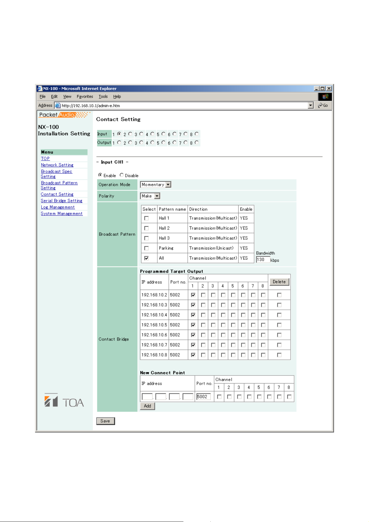
4-13
Chapter 4: SYSTEM SETTINGS (SETTING USING BROWSER)
6. CONTACT SETTING
When the NX-100/100S unit's contact input is activated, its set broadcast pattern starts broadcasting while
simultaneously enabling other unit's contact outputs. Here, contact input and output settings are performed.
This figure represents the NX-100.
(1) Contact Selection
Select the contact to be set. Selecting the input or output channel number of the contact displays its
contact's setting contents.
(2) Enable/Disable Selection
Select "Enable" or "Disable" for the contact.
Select "Enable" when using the contact function. All setting items are then ready for entry.

4-14
Chapter 4: SYSTEM SETTINGS (SETTING USING BROWSER)
6.1. Contact Input Setting
Set the broadcast pattern to be started, and the contact bridge. When the contact input is selected, the screen
will switch over to the contact input setting screen. Select [Enable] and set the contact input contents.
(1) Operation Mode
Select from [Momentary] and [Latch]. Operations are as follows:
Momentary: The designated broadcast pattern or other unit's contact is activated while the input is ON.
The start mode stops when the input is OFF.
Latch: When the input is turned on, the designated broadcast pattern or other unit's contact is
activated, and the start mode continues even if the input is turned OFF. The start mode stops
when the input is turned ON again.
on
(2) Polarity
Set to either [Make] or [Break].
Make: ON when contact is closed.
Break: ON when contact is opened.
• Momentary
Make
ON
Contact input
Break
ON
Broadcast and
contact data
• Latch
Make
Break
Broadcast and
contact data
Contact input
Contact input
Contact input
ON
ON
ON
ON
ActivationStop
50 ms or more
50 ms or more
Activati
ON
ON
Stop
ON
ON

4-15
Chapter 4: SYSTEM SETTINGS (SETTING USING BROWSER)
(3) Broadcast Pattern
The NX-100/100S unit's list of programmed broadcast patterns is displayed. Select the pattern to be
started.
Patterns which cannot be broadcast due to the Broadcast Spec settings are highlighted in red with a "NO"
displayed in the corresponding "Enable" column. Disabled broadcasts are usually caused by incorrect
multicast or transmission sampling frequency settings (for instance, local broadcasts cannot be made at
32 kHz).
[Select]
Select the pattern to be started. When cancelling the selection, click on the same checkbox again to
remove the tick.
[Pattern name]
Displays the programmed broadcast pattern name.
[Direction]
Displays the type of broadcasting.
Transmission (Multicast): Transmits a single stream broadcast to multiple units. Multicast must be set to
"Yes" in the Broadcast Spec Setting.
Transmission (Unicast): Transmits a single stream broadcast to a single unit.
Reception: Receives broadcasts from the target unit.
Local: Broadcast from the original unit's input to its own output.
[Enable]
Indicates whether or not the programmed broadcast pattern can be broadcast. If "NO" is displayed for a
pattern, review the Broadcast Spec settings.
[Bandwidth]
Indicates the total bandwidth used by the set pattern.
Caution
Broadcasts cannot be made if the setting exceeds the available bandwidth.
(4) Contact Bridge
The Contact Bridge refers to the function that enables the contact outputs of other connected unit or
original unit when the original unit's contact input is activated. Here, select NX-100/100S contact outputs
to be activated when the original unit's contact input is activated.
[Programmed Target Output]
Tick on the appropriate boxes when wishing to change only the programmed target unit's contact output
channel. Tick the corresponding rightmost checkbox to select programmed target units to be deleted, then
click on the Delete button to remove from the list.
[New Connect Point]
When performing initial programming, enter the new target unit's IP address, contact control port number
and select the channel number, then click on the Add button.
Entering the original unit's IP address and port number as a new connecting point permits the original
unit's contact output to be activated.
(5) Save button
Updates the NX-100/100S setting file.
Caution
Never restart the unit or turn off the power during updates, or while the STATUS indicator on the front
panel of the NX-100/100S is flashing.

4-16
Chapter 4: SYSTEM SETTINGS (SETTING USING BROWSER)
6.2. Contact Output Setting
Set the contact output to be activated when the NX-100/100S is enabled by other unit or the operation
program. Selecting a contact output will switch the display to the contact output setting screen. Select
"Enable" and set the contact output contents.
This figure represents the NX-100.
(1) Mode
Select Mode from [Standard], [STATUS Output], and [ERROR Output].
Standard: Provides output by way of control from a PC or contact inputs of other units or original
unit.
STATUS Output: Provides contact output synchronizing with the unit's STATUS indicator operation.
ERROR Output: Provides contact output synchronizing with the unit's ERROR indicator operation.
Note
To use the Contact bridge function, select [Standard].

4-17
Chapter 4: SYSTEM SETTINGS (SETTING USING BROWSER)
(2) Type
Select from [Momentary] and [Latch].
Momentary: Provides output during the period between receiving an activation request and receiving a
stop request.
Latch: Provides 1 second of output upon receiving an activation request and 1 second of output
upon receiving a stop request.
Note
[Latch] cannot be selected when setting Mode to [STATUS Output] or [ERROR Output].
Caution
The unit's correct operation cannot be ensured if both activation and stop signals
are received during the 1-second output interval.
(3) Polarity
Select Polarity from [Make] and [Break].
Make: ON when the contact is closed.
Break: ON when the contact is opened.
(4) Contact OFF Delay Time [sec]
Enter an OFF delay time of 0 – 60 seconds for the duration between receiving a termination request and
actually turning OFF the contact. When in Resend mode and making broadcasts with longer delay times,
set the OFF delay time to correspond to the delay time.
Note
For more information regarding OFF delay time, refer to p.6-4.
(5) Save button
Updates the NX-100/100S setting file.
Caution
Never restart the unit or turn off the power during updates, or while the STATUS indicator on the front
panel of the NX-100/100S is flashing.
• Momentary
Make
Break
• Latch
Make
Break
Broadcast and
activation data
Contact output
Contact output
Broadcast and
activation data
Contact output
ON
ON
ON
1 s
Activation Stop
Activation Stop
ON
ON
ON
ON
Contact output
ON
1 s
ON
ON

4-18
Chapter 4: SYSTEM SETTINGS (SETTING USING BROWSER)
7. SERIAL BRIDGE SETTING
NX-100 only
Perform serial bridge settings.
(1) Enable/Disable Selection
Select "Enable" when using this function. All items can be ready for entry.
(2) Network Setting
[Protocol]
Select the serial bridge communication configuration.
TCP Server: The original unit carries out communications as a TCP server. The NX-100 unit connected to
this server must be set as a TCP client in its protocol settings.
TCP Client: The original unit carries out communications as a TCP client. The target NX-100 unit must
be set as a TCP server in its protocol settings.
UDP: Carries out communications using UDP. The target NX-100 unit's protocol settings must be
set to UDP.
[Target Unit's IP Address]
Enter the target unit's IP address and port number.
Note
Enter the global IP address if using the Internet.

4-19
Chapter 4: SYSTEM SETTINGS (SETTING USING BROWSER)
(3) Serial Port Setting
[Baud Rate]
Select [9600], [19200], [38400], [57600], or [115200]
[Data Length (bit)]
Select to [7 bits] or [8 bits].
[Parity]
Select [Even], [Odd], or [None].
[Stop Bit]
Select [1 bit] or [2 bits].
[Flow Control]
Select the type of flow control.
None: Flow control is not performed.
Xon/Xoff: Performs software flow control.
Hardware: Performs hardware flow control.
(4) Other
[Automatic Cutoff Time (minutes)]
Set the time interval (timeout duration: 0 – 60 minutes) before the connected unit is automatically
disconnected following the end of the last communication. The connected unit is not disconnected if the
timeout duration is set to [0]. This function is only available for TCP connections.
[Transmit/Receive RAW data.]
Tick the checkbox when transmitting and receiving raw data. Data with control information to be utilized
between NX-100 units is usually transmitted, but raw data communications are generally carried out
without such control information. However, when communications with other connected units are cut off,
this cannot be detected. Raw data communications are only possible while in TCP connection mode.
(5) Save button
Updates the NX-100 setting file.
Caution
Never restart the unit or turn off the power during updates, or while the STATUS indicator on the front
panel of the NX-100 is flashing.
Note
Serial bridge function data can be transmitted at every 20 ms intervals or when its data length becomes 1024
bytes within 20 ms. This serial bridge function cannot be used for the equipment that communicate with data
less than 1024 bytes long at intervals shorter than 20 ms.

4-20
Chapter 4: SYSTEM SETTINGS (SETTING USING BROWSER)
8. LOG MANAGEMENT
The unit's operation logs are displayed and saved.
This figure represents the NX-100.
(1) Operation Log button
Displays the NX-100/100S unit's operation log.
(2) Stream Log button
Displays streaming reception log.
(3) Log Save button
Saves log as a file in the PC.
(4) Operation Status button
Displays the NX-100/100S unit's current operation status.

4-21
Chapter 4: SYSTEM SETTINGS (SETTING USING BROWSER)
8.1. Operation Log
The operation log screen is displayed when the Operation Log button is pressed on the Log Management
Menu screen.
This figure represents the NX-100.
[Operation button]
(1) Latest button
Updates the operation log to current data.
(2) Prev. Page button
Moves to the previous page.
(3) Next Page button
Moves to the next page.
(4) Clear button
Deletes all operation logs.
(5) Display Change button
Displays or hides the web access log.

4-22
Chapter 4: SYSTEM SETTINGS (SETTING USING BROWSER)
[Items in the Table]
(1) Time
Indicates the time the event took place.
(2) Category
Indicates the type of log.
SESSION: Communications between units
REMOTE: Control by a PC
SWITCH: Monitoring of the contact input and the contact control
SERIAL: Serial bridge operating status
SYSTEM: System information
WEB: Web server access log
STREAM: Status of audio stream
(3) Requesting Source
Indicates the IP addresses of communication parties or requesting sources of the events such as
designating contact channels.
(4) Contents
Indicates the contents of events. Levels are "Normal" (green), "Caution" (yellow), and "Error" (red).

4-23
Chapter 4: SYSTEM SETTINGS (SETTING USING BROWSER)
8.2. Saving Operation Logs
Follow the procedures below to save logs to a PC:
Step 1. Press the Operation Log Save button on the Log Management Menu screen.
A dialog is displayed.
Step 2. Press the Save Button.
The screen for selecting the storage location is displayed.
Step 3. Select the storage location and enter a filename.
Tip
The default filename is "[IP address].log."
Step 4. Select [All files] for "Save as type", then press the Save button.

4-24
Chapter 4: SYSTEM SETTINGS (SETTING USING BROWSER)
8.3. Stream Logs
The Stream Log screen is displayed when the Stream Log button is pressed on the Log Management Menu
screen.
This figure represents the NX-100.
[Operation Button]
(1) Refresh button
Updates to the most recent data.
(2) Clear button
Deletes all stream reception logs.

4-25
Chapter 4: SYSTEM SETTINGS (SETTING USING BROWSER)
[Items in the Table]
(1) Current Stream
• Stream Data
• Reception Log
Correct Reception: The number of packets received correctly. (The number of error packets or
recovered packets is not included.)
Error: The number of packets whose packet length and header data are not
matched.
Restoration: The number of packets recovered by error correction or resending, out of
those that were lost due to network failures.
Loss: The number of packets not recovered, out of those lost due to network
failures.
Silent tone insertion: The number of packets that caused no sound from the audio output.
(2) Past Reception Log
The network is possibly congested when the "Loss" number increases.

4-26
Chapter 4: SYSTEM SETTINGS (SETTING USING BROWSER)
8.4. Operation Status
The Operation Status screen is displayed when the Operation Status button is pressed on the Log
Management Menu screen.
This figure represents the NX-100.
[Operation Button]
(1) Refresh button
Updates status to the most recent data.
[Item in the Table]
(1) Broadcast
Indicates the condition of the current broadcast.
(2) Contact
Indicates the conditions (ON/OFF) of the contact input and output.

4-27
Chapter 4: SYSTEM SETTINGS (SETTING USING BROWSER)
9. SYSTEM MANAGEMENT
Note
The System Management Utility area is not displayed when in Management Setting mode.
[Unit Data]
(1) Unit Name
Enter the NX-100/100S unit's name.
(2) Audio Input Unit Name
Enter a name when connecting the audio input unit.
(3) Audio Output Unit Name
Enter a name when connecting the audio output unit.
This figure represents the NX-100.

4-28
Chapter 4: SYSTEM SETTINGS (SETTING USING BROWSER)
(4) Unit Data Change button
Updates only system setting data in the NX-100/100S setting file.
Caution
Never restart the unit or turn off the power during updates, or while the STATUS indicator on the front
panel of the NX-100/100S is flashing.
[User Data]
System names and passwords can be changed.
Step 1. Enter the new system name in the System Name frame.
Tips
• The current system name is displayed.
• Use up to 15 alphanumeric characters to enter the system name. (It can be set to blank.)
Step 2. Enter a new password in the New Password frame.
Tip
Use up to 15 alphanumeric characters to enter the password. (It can be set to blank.)
Step 3. To confirm, enter the password entered in Step 2 in the New Password (verification) frame.
Enter the same password again for verification.
Step 4. Press the User Data Change button.
Updates only user data in the NX-100/100S setting file.
Caution
Never restart the unit or turn off the power during updates, or while the STATUS indicator on the front
panel of the NX-100/100S is flashing.

4-29
Chapter 4: SYSTEM SETTINGS (SETTING USING BROWSER)
[System Management Utility]
(1) Setting File Upload
Uploads backed up setting files.
Step 1. Press the Browse button.
The Choose file dialog opens.
Step 2. Select the backup file (.cfg extension), then press the Upload button.
Update of the setting file begins.
Caution
Never restart the unit or turn off the power during updates, or while the STATUS indicator on the
front panel of the NX-100/100S is flashing.

4-30
Chapter 4: SYSTEM SETTINGS (SETTING USING BROWSER)
(2) Setting File Download
Backs up the setting file.
Step 1. Press the Download button.
A dialog is displayed.
Step 2. Press the Save button.
A dialog is displayed.
Step 3. Select the save destination and enter a filename.
Tip
The default filename "[IP address].cfg" is first displayed.
Step 4. Select [All files] for "Save as type", then press the Save button.

4-31
Chapter 4: SYSTEM SETTINGS (SETTING USING BROWSER)
(3) Delete All Settings
Deletes all settings to return them to their original settings when supplied.
The unit is factory-preset as follows:
IP Address: 192.168.1.1
Unit Name: NX-100S
System Name: NX-100
Password: guest
Other settings can be viewed with a browser or the setup program.
(4) Firmware Update
Updates firmware.
Step 1. Press the Browse button.
The Choose file dialog opens.
Step 2. Select the NX-100 firmware (".bin" extension), then press the Firmware Update button.
Caution
Never restart the unit or turn off the power during updates, or while the STATUS indicator on the
front panel of the NX-100/100S is flashing.
Tips
• The latest versions of the following software and manuals are open to the public on the Toa's
download site http://www.toa-products.com/international/: NX-100 firmware, NX-100 software
(Setup program and Operation program), and Instruction manuals (Installation setup manual
and Operations manual). Please download them from the above web site.
• The version of each instruction manual is in the lower right corner on the last page expressed in
a year-month format. Example: "200406" represents 2004, June.
(5) Restart button
Restarts the NX-100/100S unit. Be sure to restart any time the setting contents are changed. The change
is only enabled after restart.
Cautions
• Never restart the unit or turn off the power during updates, or while the STATUS indicator on the front
panel of the NX-100/100S is flashing.
• Broadcasts are interrupted when the unit is restarted.

Chapter 5
OPERATION SETTINGS
(NX-100 OPERATION PROGRAM)
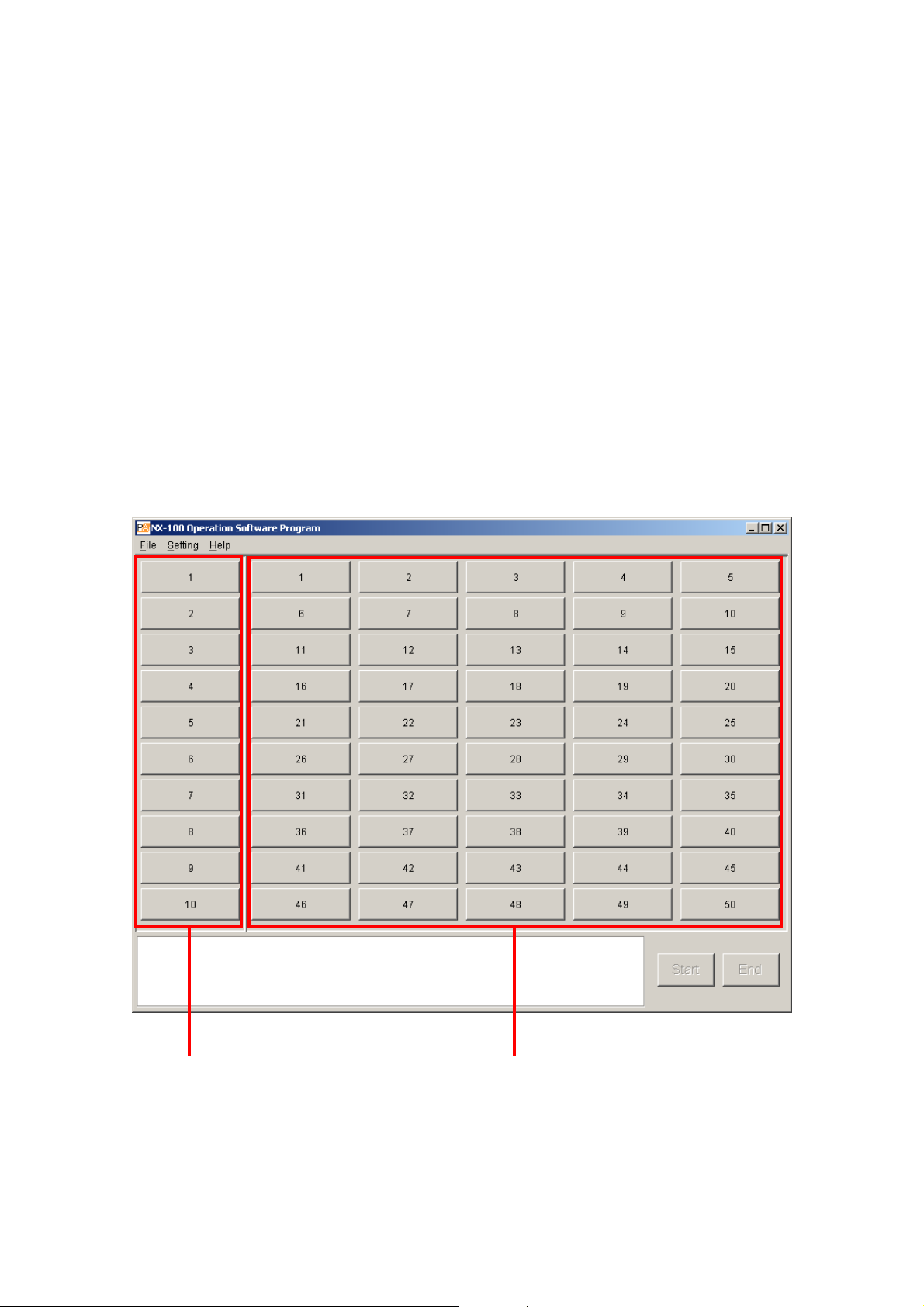
5-2
Chapter 5: OPERATION SETTINGS (NX-100 OPERATION PROGRAM)
1. NX-100 OPERATION PROGRAM SUMMARY
This operation program is used to set the control buttons used for broadcasts, and activate set NX-100 and
NX-100S broadcast patterns*1or operate the contact output*2.
*1The broadcast pattern is determined by the combination of the contents of the sound source and the units
targeted to receive the broadcast. One target unit can be set for unicast streaming, and up to 64 units for
multicast streaming. Only one pattern can be set per button.
Note
For more information concerning broadcast pattern settings, refer to Chapters 3 and 4.
*
2
The NX-100's and NX-100S' contact output is controlled via the network. Up to 64 units x 8 channels can
be controlled per button.
2. STARTUP AND INITIAL SCREEN
Either double-click on the Operation program icon created on the desktop at the time of program installation or
double-click on the application [nx100_control.jar] installed in the software folder. The following initial window
(with nothing set in it) will then be displayed.
Group buttons Selection buttons
The 10 Group buttons and 50 Selection buttons are displayed, with each button being numbered before any
button setting is performed.

5-3
Chapter 5: OPERATION SETTINGS (NX-100 OPERATION PROGRAM)
3. OPERATION SCREEN DESCRIPTION
This section explains the screen layout, using the accompanying operation setting screen as an example.
(2)
(5)
(1)
(3)
(4)
(1) Selection Button
Selects the broadcast pattern and contact output to be activated. The number of buttons programmed is
50 by default. One broadcast pattern or up to 64 units X 8 contact output channels can be set per
Selection button.
(2) Group Button
Used to simultaneously select two or more Selection buttons. The number of buttons programmed is 10 by
default.
(3) Start Button
Starts up the activation contents (broadcast pattern and contact output) selected with the Selection or
Group buttons.
This button can be hidden from display depending on the setting.
(4) End Button
Terminates activated broadcasts or contact outputs.
(5) Message Display Area
Displays responses to operations or the contents of errors.
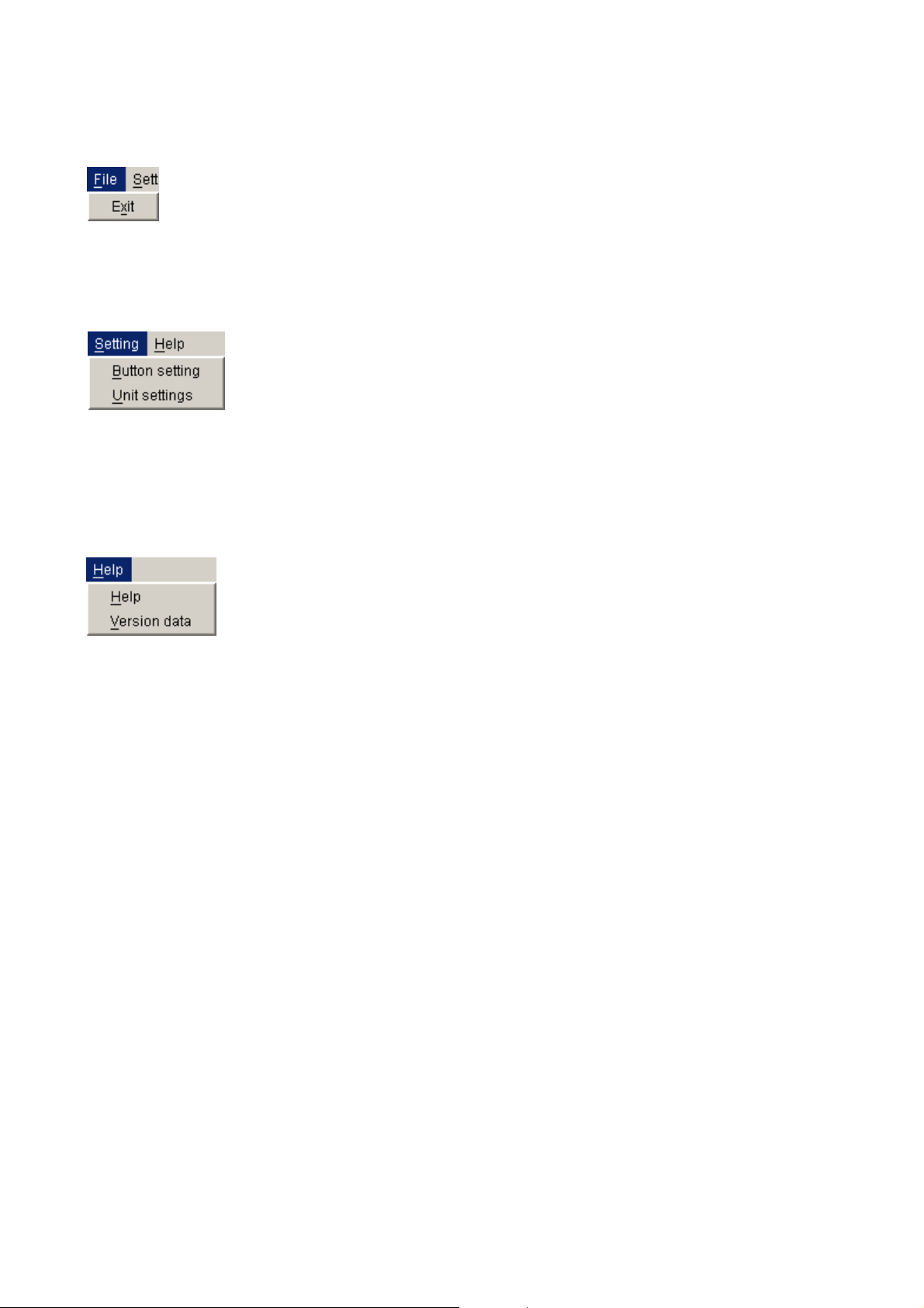
5-4
Chapter 5: OPERATION SETTINGS (NX-100 OPERATION PROGRAM)
4. MENU
4.1. File
Exit: Terminates the software program currently in use.
4.2. Settings
Button setting: Set the Selection button and the Group button.
Unit settings: If there is a unit that has not yet been programmed into the system using the NX-100 setup
program, select this menu item to add it as the operable unit.
4.3. Help
Help: Displays help contents.
Version data: Indicates the version number of the software program in use.

Before performing the setting using the Operation program
Set the NX-100 and NX-100S units in the system using the NX-100 Setup program.
Broadcast settings that will be activated by the operation program must all be programmed into each
connected unit as the "broadcast pattern."
5-5
Chapter 5: OPERATION SETTINGS (NX-100 OPERATION PROGRAM)
5. SETTING PROCEDURES USING THE OPERATION PROGRAM
(1) Add the unit to the system.
NX-100 and NX-100S units set with the Setup program as system units are automatically
recognized as operable units by the NX-100 Operation program. NX-100 and NX-100S
units which were set without using the NX-100 Setup program, such as the units
connected through the Internet, can be added to the system setting using the NX-100
Operation program.
(3) Set the Selection buttons.
Set the Selection buttons that select the broadcast patterns or contact outputs to be activated.
Use the broadcast patterns which were programmed into the operable units (those units set with the
NX-100 Setup program and added in Step (1) above).
Only one pattern can be programmed into each Selection button.
When simultaneously activating two or more broadcast patterns with the Group button, all of the
broadcast patterns to be activated must first be programmed into the Selection buttons.
(4) Set the Group buttons.
Use the Group button when wishing to simultaneously activate two or more broadcast patterns. Select
and assign the desired Selection buttons to each Group button.
If the system contains NX-100 and NX-100S
units not set with the Setup program such as
the units connected through the Internet.
If only NX-100 and NX-100S units
set with program are used.
If simultaneously activating multiple
broadcast patterns
The NX-100 Setup program cannot be used to set NX-100 and NX-100S units connected
via the Internet.
(2) Set the Button layaout.
Edit the Button layout.
Edit the layout of the Selection and Group buttons on the operation screen.

5-6
Chapter 5: OPERATION SETTINGS (NX-100 OPERATION PROGRAM)
6. UNIT SETTING ADDITION
Set the broadcast pattern data necessary for the Selection button setting using the NX-100 Setup program
(refer to Chapter 3). If a unit setting file has already been created, the data is automatically loaded. However,
NX-100 and NX-100S units which are connected through the Internet and cannot be set with the NX-100
Setup program must be added using the Operation program. In order to activate the NX-100 and NX-100S
broadcast patterns set using a browser (refer to Chapter 4), add the unit setting using the following procedure:
Step 1. Turn on the power to the NX-100 and NX-100S units for which the unit setting is to be added to make
connections possible.
Step 2. Start up the Operation program and select Setting → Unit settings.
The User Authentication screen is then displayed.
Step 3. Enter the system name and the password (the same password used in the setup program), then
press the OK button.
Notes
• Both the system name and the password are case-sensitive.
• The default system name is preset to "NX-100" and the password to "guest" when the unit is
shipped from the factory. To change, refer to p. 3-31 or p. 4-28.
The Unit Settings window is displayed if the system name and the password are correctly entered.
Note
In the initial startup mode, nothing is displayed in the Name, IP Address, Web, TCP and UDP
columns.

5-7
Chapter 5: OPERATION SETTINGS (NX-100 OPERATION PROGRAM)
Step 4. Press the Add button.
A Unit Addition dialog is displayed.
Step 5. Enter the IP address and port number (Web server, TCP start port number, and UDP start port
number), then press the OK button.
The entered data is displayed on the Unit Settings window.
Step 6. To save the changed contents without quitting the Unit Settings screen, press the Apply button.
The NX-100 and NX-100S units with the entered IP addresses are connected, and their setting data
downloaded.
The names are displayed on the Unit Settings screen when downloaded. The names cannot be
edited.
The downloaded setting contents are saved to the data folder in the software program installation
folder.
Step 7. Press the OK button after all necessary NX-100 and NX-100S units have been added.
The NX-100 and NX-100S units with the entered IP addresses are connected, and their setting data
downloaded.
After the downloading of all units is completed, the Unit Settings screen is closed.
The downloaded setting contents are saved to the data folder in the software program installation
folder.
Tips
• When a unit cannot be connected, the dialog [Connection failure to "
XX
". Delete?] is displayed.
Pressing the OK button deletes the faulty NX-100 or NX-100S from the Unit Settings screen list,
and the data is saved.
Pressing the Cancel button cancels the setting change. Setting can be attempted again after
confirming the setting contents.
• To delete an NX-100 or NX-100S unit from the Unit Settings screen list, select the desired unit and
press the Delete button.

5-8
Chapter 5: OPERATION SETTINGS (NX-100 OPERATION PROGRAM)
7. EDITTING THE BUTTON LAYOUT
The Start button can be set to enable or disable, and the layout of the Selection and Group buttons can be
edited.
Step 1. Start the Operation program and select [Setting] → [Button setting].
The User Authentication screen is displayed.
Step 2. Enter the system name and the password (the same system name and password entered in the setup
program), then press the OK button.
Notes
• Both the system name and the password are case-sensitive.
• The default system name is preset to "NX-100" and the password to "guest" when the unit is
shipped from the factory. To change, refer to p. 3-31 or p. 4-28.
The Button Setting screen is displayed if the system name and the password have been correctly
entered.

5-9
Chapter 5: OPERATION SETTINGS (NX-100 OPERATION PROGRAM)
Step 3. Click on the Button layout tab, then perform settings for each item shown on the screen.
In the initial startup mode, the following screen is displayed.
(1)
(2)
(3)
(1) Enable start button
When the box is unchecked, the Start button on the operation screen is disabled and hidden. In this case,
pressing the Selection or Group button automatically starts connection to the NX-100 or NX-100S
programmed for that button.
[Number of buttons]
Set the number of buttons on the operation screen.
There is no limit to the number of buttons that can be set.
(2) Single selection button: horizontal, vertical
Set the number of Single Selection buttons.
The number is preset to 5 horizontal by 10 vertical buttons (total 50 buttons).
(3) Group button: horizontal, vertical
Set the number of Group buttons.
The number is preset to 1 horizontal by 10 vertical buttons (total 10 buttons).
Step 4. Press the OK button after completing all editing tasks.
The setting contents are saved to the data folder located in the installation folder (default path:
C:\Program Files\TOA\NX-100) of the software program, and the Button Setting screen is closed.

5-10
Chapter 5: OPERATION SETTINGS (NX-100 OPERATION PROGRAM)
(1) (2) (3)
[Registration Contents List]
(1) Visible
Displays or hides the Selection buttons.
(2) No.
Selection button numbers. These numbers cannot
be changed.
The buttons are arranged in the order of the
button number (see figure at right) on the
operation screen.
(3) Indication Name
The name of the Selection button to be displayed
on the operation screen.
Selection button layout
(Example when 5 horizontal
by 10 vertical buttons are set.)
8. SETTING THE SELECTION BUTTON CONTENTS
Program the broadcast pattern and the contact output activation setting into the Selection button.
Step 1. Click on the Single selection button tab on the Button Setting screen (p. 5-8).
The Single selection button setting screen is displayed.
(Setting screen example)

5-11
Chapter 5: OPERATION SETTINGS (NX-100 OPERATION PROGRAM)
Step 2. Click off the checkbox ticks in the Registration Contents List for Selection buttons not to be used on
the operation screen.
Buttons not marked with a tick are not displayed on the operation screen.
Step 3. Click on the Selection buttons (the No. or Indication Name area) to be edited in the Registration
Contents List.
The contents are displayed in the Edit area.
Step 4. Enter the Indication name in the Edit area.
Tip
There is no limit to the number of characters that can be entered, however the maximum number of
characters that can be displayed on the operation screen buttons for the screen size at startup is 16.
Because the number of displayed characters increases as the display screen increases in size, set
the number of characters to correspond to the screen size to be used.
Step 5. Check the broadcast pattern to be activated in the Broadcast pattern list.
Tips
• The Broadcast pattern list displays all patterns that have been programmed into all NX-100 and NX100S units in the system, including the NX-100 and NX-100S units added in the unit setting
procedure (p. 5-6).
• Only one broadcast pattern at a time can be selected.
• To clear the setting contents of the selected NX-100 or NX-100S broadcast pattern, press the
leftmost Clear button in the Edit area.
Step 6. Check the contact output to be activated in the Contact output list.
The contact channel number to be output can be selected.
(Setting screen example)
Broadcast pattern list
Contact output list

5-12
Chapter 5: OPERATION SETTINGS (NX-100 OPERATION PROGRAM)
Step 7. Check the contact channel number to be used.
Tip
To clear the setting contents of all NX-100 and NX-100S contact outputs, press the leftmost Clear
button in the Edit area.
Step 8. Press the OK button after completing all editing tasks.
The setting contents are saved to the data folder located in the installation folder (default path:
C:\Program Files\TOA\NX-100) of the software program, and the Button Setting screen is closed.
 Loading...