

INTERCOM SYSTEM
TOA EXES-5OOO
INTERCOM SYSTEM
TROUBLE SHOOTING GUIDE
TOA ELECTRIC CO., LTD.
KOBE, JAPAN
8. TROUBLE SHOOTING GUIDE
Repairing of the EXES-5000 system is basically done by
replacing defective units with goo d ones. The system's
faults in an installation can be divided into the following categories.
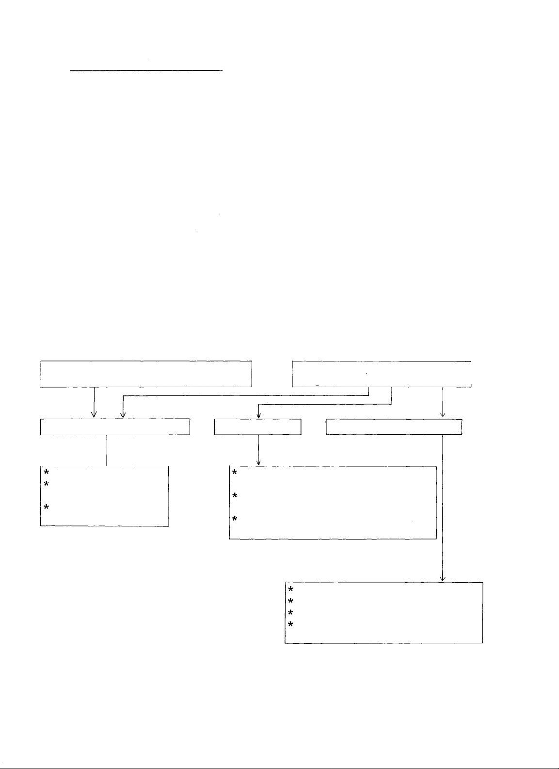
1. Faults in an exchange
2. Faults in a station
3. Cable faults
To make system repairing easier, find which category is
involved, then refer to the chart below for assistance
in fault finding.
All stations do n o t operate.
Same symptom in every station.
Fault in an exchange.
Cable fault. Fault in a station.
Power supply
Plug-in unit
(Common control)
Back wiring on
frame
Fault in specific station
only.
Mis-wiring between exchange
and terminal board.
Mis-wiring such as short,
broken wire, etc.
Misconnection in station
jack.
Ke y b o ar d switch fault.
Board assembling fault.
Speaker, microphone fault.
Microswitch
,
connecting
cable fault.
-60-
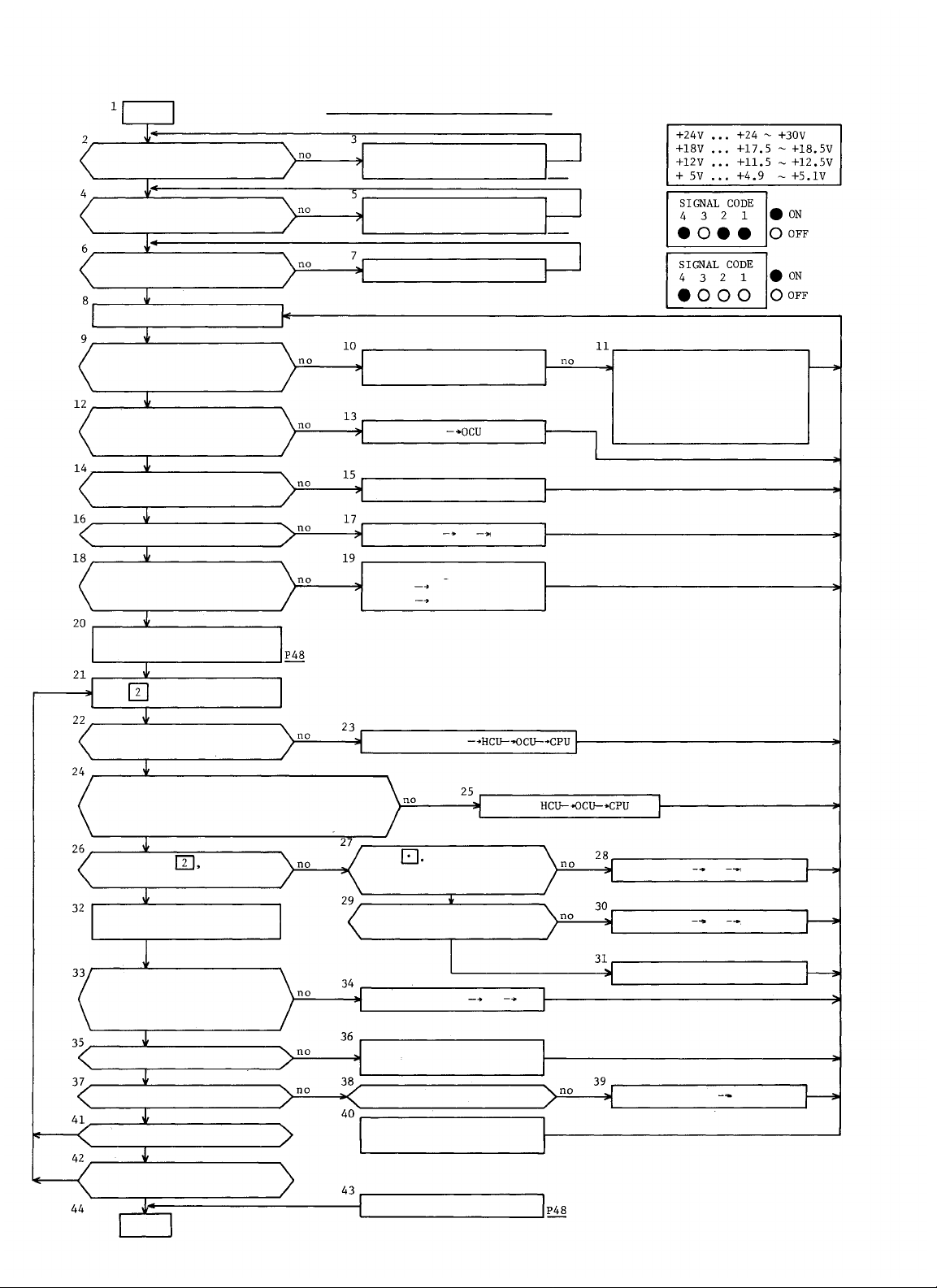
START
DIP switch on CPU
correctly set ?
Back-up battery on
CPU connected ?
Program switch on
CPU off ?
Power switch on
EXES-5000 SYSTEM CHECK FLOW CHART
Set DIP switch
according to Inst.
Plug the Jack into
Pin A.
Program switch o ff
P54
P56
Table 1:
Fig.
1
Fig.
2
Proper voltages at
each output power
terminal? (tabl 1)
No.15 of S CN SELECT on
OCU l i t brighter than
others ?
CLOCK lamp on HCU lit
brightly ?
Other lamps on HCU off ?
Station No. lamp on LMU
li t corresponding to
station connected ?
Clear all No.200
programmings
Dial
One o f LINK BUSY lamps on
HCU li t brightly ?
Turn on LINK SELECT switch(es) on HCU to make
the total number of marked number to be the
number of LINK BUSY lamp lit. The station
dialled correspond to ADDRESS-T lamp.
at an y M-station
Disconnect DC power
connection and check
Replace CPU
Replace HCU
Replace HCU
Check wiring to the
station
station
Replace Station
OCU
Replace the
LMU
Replace
CPU
If +24V or +18V is not
in the range, check
power supply (DS-510).
If
+12V
or +5V is not
in the range, replace
DC/DC inverter.
On dialling dial tone
heard ?
Call from any station
to any station
Calling station and called
station correspond to lamps
lit on ADDRESS T and R
SIG.CORD lamp lit as Fig.2
Calling tone heard ?
Two way conversation OK ?
All other links OK ?
Conversation possible
with all station ?
END
Dial
SIG. CORD lamps
on HCU lit as Fig. 1
momentary
In other links, dial
tone and lamps OK ?
Replace Station
Replace SGD — Station
wiring
In other links ?
Replace CLU or DLU
concerned
Program No.200 functions
CPU-
-61-
HCU
Replace HCU;
Replace SGD
Replace CLU or DLU
Replace Station
OCU
HCU
CPU
Station
CLU or DLU
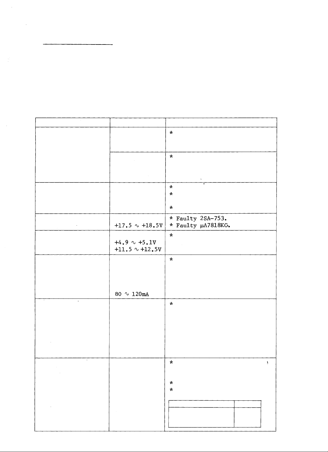
8-1. FAULT IN EXCHANGE
Before power supply check, confirm the following three
points to eliminate elementary faults:
1. Is voltage selector set correctly?
2. Is AC power supplied?
3. Is power switch O N ?
Start checking after disconnecting all wiring connected
t o D C output of the power supply unit.
SYMPTON
Exchange does n o t
operate.
Abnormal voltage
of +24V terminal.
Abnormal voltage
of
+18V.
Abnormal voltage
of +5V or
+12V.
Battery is not
charged.
CHECK-ITEM
All DC output
voltages are
correct.
All or one of
DC output
voltages are
not correct.
Right range:
+24 ~ +30V
Right range:
Right range:
Check the cur-
rent flowing
into the battery.
Right range:
Over-current flows into one
of plug-in units.
Fault in the power supply
unit DS-510.
Replace AC and DC fuses.
Incorrect setting of the
voltage selector.
Faulty power transformer.
DC/DC inverter (MIV-02) i s
defective.
Replace PCB of charging
circuitry.
AC & DC operation
lamps are OFF.
Buzzer does not
operate.
Note: Only when DC
power supply
(Battery) is
employed.
Blown AC and/or
DC fuse.
Check all DC
voltage.
All DC output
voltages are
correct.
heck all sta-
tions involv-
ed in All-Call
paging.
-62-
Replace PCB of charging
circuitry.
Over-current flows into one
of plug-in units.
(Especially on +18V)
MIV-02 is defective.
Replace fuse according to
the following.
Number of stations
0 ~ 30
31 ~ 64
65
~
Fuse
DC 5A
DC 7A
DC 10A
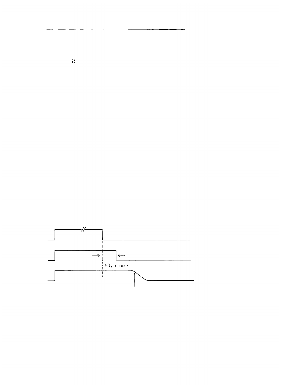
8-2. HOW TO FIND SHORT BETWEEN T-LINE AND R-LINE
If the shorted condition between T-line and R-line is not
corrected for a long time, it may burn out the guard re-
sistor (330 , 1/2W) on th e LMU board. Therefore, find
the shorted line according to the following procedure:
1. Turn off the privacy switch on all stations in the
system.
2. Turn on the power switch of t he system for several
seconds, then, turn it off.
3. Watch the lamps on the LMU panels. The lamps on
normal lines will go off after approximately 0.5
second. The lamps o n the shorted lines will stay
on more than 0.5 second.
Power ON
Lamp ON
Lamp ON
(Brighter than normal)
OFF
Normal
Abnormal
(Short)
Lamp goes off gradually
-63-

1. One of transmitting lines (T-Line) is disconnected.
Station
EXCHANGE
Symptom
LMU Lamps
2. One of receiving lines (R-Line) is disconnected.
Sympton: 2-1 A can make dialing without dialing tone.
A can make dialing.
1-1
1-2
A can hear B .
B can not hear A .
1-3
Noise is heard at B .
1-4
Noise increases at B when Press-To-Talk b ar is
1-5
pressed at A .
Normal
EXCHANGE
2-2 When B dials A , busy tone or dial tone will be
heard at B immediately after the calling tone.
LMU Lamps ----- Normal
-64-

3. T-Line and R-Line are shorted or mixed up .
Shorted or mixed up
EXCHANGE
Symptom
A can not dial.
3-1
Conversation is impossible between stations.
3-2
When B dials A , noise will be heard at B
3-3
immediately after the calling tone.
LMU Lamps
Brighter than normal.
4. T-Line and R-Line are connected conversely.
Sympton:
LMU Lamps
A can not make dialing.
4-1
Conversation is impossible between stations.
4-2
When B dials A , noise will be heard at B .
4-3
Brighter than normal.
-65-

8-3. FAULT IN SPECIFIC STATION ONLY
Find the cause according to the following table if the fault
lies with a specific station only, not with all stations.
Dialing can not
be made at privacy
off mode.
Specific key does
not operate.
Calling tone can
not be heard.
Dialing tone can
not b e heard on
dialing.
Sound from the
other party can
not be heard.
CHECK-ITEM
LMU Lamp is
off.
Specific Lamp
on LMU is
brighter than
normal.
LMU Lamp is
on in normal.
Replace the
station and
make sure that
the station
is not faulty.
Same sympton
remains even
if the station
is replaced.
Becomes normal
if the station
is replaced.
CAUSE
Disconnection of both T & R-Lines.
Guard resistor 330 on LMU is
burned out due t o T & R-Lines
short.
T & R-Lines are shorted.
Fault in the station.
(Replace PCB board.)
Fault in key board switch or
matrix circuitry.
Fault in t he dial generator.
(Replace PCB board.)
Short or open in R-Line.
Fault in th e demodulation cir-
cuitry on LMU.
(Check LM-380, MT-547.)
Disconnection of R-Line or im-
proper connection of the station
connector.
Fault in MT-547 on LMU.
Station fault.
So un d is not trans-
mitted to the other
party.
On dialing, noise
is heard by the
called party.
Same sympton
remains even
the station
is replaced.
Becomes normal
if the station
is replaced.
Same sympton
remains even
the station is
replaced.
Becomes normal
if the station
is replaced.
Short or open in T-Line.
Fault in the modulation cir-
cuitry on LMU.
Fault in MIC circuitry o f the
station. (Replace MIC or PCB)
One of T-Lines is disconnected.
Fault in MIC element.
Fault in T-Line of the station.
Low frequency oscillation o f
MIC AMP. (Faulty bypass capaci-
tor)
-66-

Sound of the other
party is broken
during call.
Same symptom
remains even
the station
is replaced.
Adjust the volume control of
station speaker if the room
produces reverberation.
(Lower the volume.)
Increase the gain of MIC AMP.
Replace PCB after checking if
MIC unit is n ot touching its
case.
Immediately after
the calling tone,
the line switches
to cancel, busy,
dial tone, etc.
Same symptom
remains even
the station
is replaced.
Becomes normal
if the station
is replaced.
One of R-Lines is disconnected.
Fault in photo coupler PC-504
on
LMU.
Fault in MT-547 on LMU or in
the station.
One of the R-Lines is discon-
nected or the station connector
is not connected properly.
-67-

8-4. SPEECH AND FUNCTION TEST
1. Speech Test
After completing the wiring check and the power supply
and exchange test according to the system flow chart,
the speech test for each station can then take place.
IMPORTANT NOTE
Before testing, all programming (Secretary transfer,
Master/Substation, Executive Priority Function) must
be cleared from station No.200 by turning on the PRO-
GRAM switch of the CPU, or the speech test ca n n o t
proceed correctly.
Call every station on e by on e from a ny master station
and examine the speech quality and sound volume.
The sound volume can be adjusted by the volume on the
rear of the station. (Fully clockwise for maximum)
A call to a station in the room produces reverbera-
tion a nd ma y present broken sound. Turn down the
volume of the station speaker until the sound becomes
normal.
Each station must be located properly where no feed-
back will occur between station and external speakers.
The gain adjustment of the paging amplifier is also
important in order to avoid troublesome feedback.
The Press-To-Talk ba r on the station keyboard must be
used for the speech test when stations are installed
in high noise areas (more than 60dB noise).
Speech quality (broken sound, natural conversation,
tone quality, etc.) must be tested with each line in
the CLU or DLU employed in the system.
-68-

2. Function Test
Check all employed functions with a few stations near
the exchange.
Check "User Programmable Functions" at stations involved after the programming from station 200.
Secretary Transfer: Is transfer made correctly
with the privacy switch on
at the executive station.
Master/Substation : Touch dial
at substation
can call its master station.
Executive Priority: Is this function operated at
stations involved.
Use all number keys including
To-Talk bar, Vol. L/H and privacy switch to test
and
, Press-
all functions.
EXAMPLE:
Both calling and conversation tests with
station number 200 through 209.
Change the position of Vol. L/H and make
sure that the switch works.
Turn the privacy switch ON. Is privacy
tone heard from the station when some-
one calls?
-69-

MEMO

MEMO

TOA ELECTRIC CO., LTD.
KOBE, JAPAN
Printed in Japan
EX5(7)-01R(79-2)
 Loading...