

OPERATING INSTRUCTIONS
STEREO MIXER M-243
THE LIGHTNING FLASH WITH
ARROWHEAD WITHIN A TRIANGLE IS
INTENDED TO TELL THE USER THAT
CAUTION
TO REDUCE THE RISK OF ELECTRICAL
SHOCK, DO NOT REMOVE COVER.
NO USER SERVICEABLE PARTS INSIDE.
REFER SERVICING TO QUALIFIED
SERVICE PERSONNEL.
PARTS INSIDE THE PRODUCT ARE A
RISK OF ELECTRIC SHOCK TO
PERSONS.
THE EXCLAMATION POINT WITHIN A
TRIANGLE IS INTENDED TO TELL THE
USER THAT IMPORTANT OPERATING
AND SERVICING INSTRUCTIONS ARE
IN THE PAPERS WITH THE APPLIANCE.
TABLE OF CONTENTS
HANDLING PRECAUTIONS
GENERAL DESCRIPTION
FEATURES
NOMENCLATURE AND FUNCTIONS
INTERNAL SWITCH SETTINGS
BLOCK AND LEVEL DIAGRAM
DIMENSIONAL DIAGRAM
SPECIFICATIONS
Please follow the instructions in this manual to obtain the optimum results from this unit.
We also recommend that you keep this manual handy for future reference.
2
2
2
3,4
5
6
6
7
TOA Corporation

1. HANDLING PRECAUTIONS
Operating voltage range is AC mains ±10% (50/60Hz).
Keep corrosive chemicals and beverages away from the unit as they may be spilt.
When any irregularity is found, be sure to contact your nearest TOA dealer. Make no further attempt to use
the unit to avoid electrical shocks.
2. GENERAL DESCRIPTION
The TOA M-243 is a 19" rack mountable (1 unit size) stereo mixer that comes with two monaural inputs, four
stereo inputs, one stereo output and two monaural outputs.
3. FEATURES
Two monaural inputs, four stereo inputs, one stereo output, and two monaural outputs. Each input signal
can be assigned to three outputs.
Sub-input for each bus line to the stereo output and two monaural outputs.
Microphone input or line input selectable for monaural input depending on the signal level. Internal limiter
minimizes signal distortion due to excessive input. Internal switches operate a high-pass filter function in the
input circuit, and a pad (20dB) function in the microphone input.
Signal clip indicator.
Automatic muting function (can be switched on and off) detects the monaural input signal and automatically
mutes the stereo output signal.
Stereo output has a recording output and equalizers for high and low frequencies.
Two monaural outputs also function as stereo sum outputs by internal switch setting.
Assign button cover serves as a writing block.
Knobs supplied in different colors for easy association with their respective controls.
2
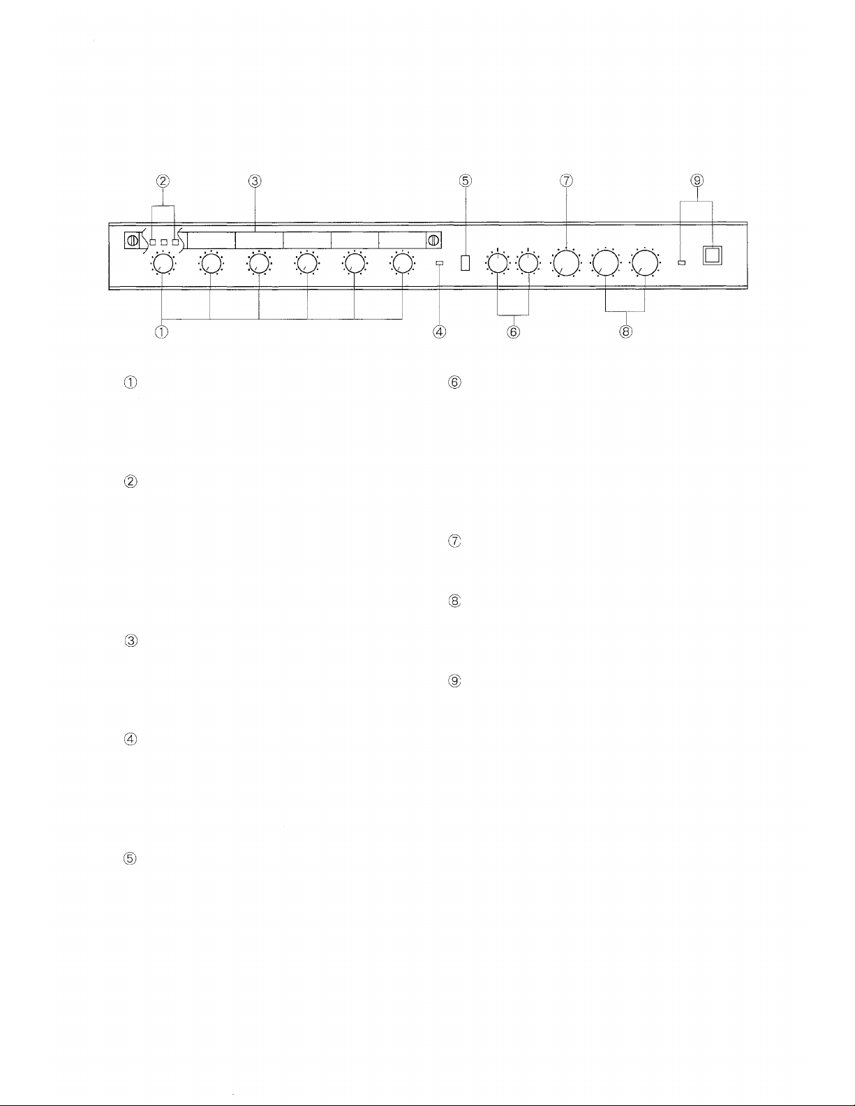
4. NOMENCLATURE AND FUNCTIONS
[Front Panel]
Input level controls [1-6] (1-2 : Monaural input,
3-6 : Stereo input)
These controls adjust the input level of each
channel.
Assign buttons [ST, 1, 2]
These buttons select the output to which the
post-input level control signals are delivered.
ST : Stereo output
1 : MONO 1 output
2 : MONO 2 output
Assign button cover
This cover protects the assign switch setting
from accidental change. It can also be used as
a writing block.
Clip indicator [PEAK]
This lamp lights when the signal reaches 3dB
below clipping. Adjust the signal level using
individual input level controls so that this lamp
lights only accidentally.
Equalizer controls [EQ : LOW, HIGH]
These controls adjust stereo output signal tone.
LOW : Low frequency adjustment
(20Hz, ±15dB shelving)
HIGH : High frequency adjustment
(20kHz, ±15dB shelving)
Stereo output level control [STEREO]
This control adjusts a stereo output level.
Monaural output level controls [MONO 1, 2]
These controls adjust each monaural output
level.
Power button and power lamp [POWER]
This button switches power on (the power lamp
lights) and off (the lamp is extinguished).
Mute ON/OFF button [AUTO MUTE]
This button turns on the muting facility when
pressed. (The muting indicator will light.) By
detecting the signal assigned to the stereo
output from channel 1 or 2, the signal assigned
to stereo outputs from channel 3 through
channel 6 is muted. (The signal assigned to the
monaural output is not muted.)
3

[Rear Panel]
For technical details of each input and output, refer to the section "8. SPECIFICATIONS".
Monaural input terminals (1,2) [MIC, LINE]
Select either MIC or LINE for connection. If both are connected, LINE input takes precedence.
Stereo input jacks (3-6) [L , R]
Only CH6 RCA jacks are connected in parallel with phone jacks.
Stereo sub-input terminals [SUB IN STEREO L / M, R]
Signals from these terminals are assigned to stereo output buses that go to the stereo output. Connecting
only "L" will input to both "L" and "R".
Monaural sub-input terminals [SUB IN MONO 1,2]
Signals from these terminals are assigned to monaural output buses that go to monaural output 1 and 2.
Recording output jacks [REC L , R]
These stereo recording jacks output the signal from the stereo output bus.
Stereo output jacks [STEREO OUT L , R]
Monaural output jacks [MONO OUT 1, 2]
These jacks also function as stereo sum outputs by internal switch setting. (Refer to the section
"5. INTERNAL SWITCH SETTINGS".)
AC inlet
Connect the supplied power cord to this inlet.
4

5. INTERNAL SWITCH SETTINGS
[CAUTION]
THESE SERVICING INSTRUCTIONS ARE FOR USE BY QUALIFIED PERSONNEL ONLY. TO AVOID
ELECTRIC SHOCK DO NOT PERFORM ANY SERVICING OTHER THAN THAT CONTAINED IN THE
OPERATING INSTRUCTIONS UNLESS YOU ARE QUALIFIED TO DO SO. REFER ALL SERVICING TO
QUALIFIED SERVICE PERSONNEL
The M-243 mixer enables the following functions by setting internal switches.
(1) [PAD switch]
Setting this switch to IN position will place a pad (20dB) in the monaural input (MIC input).
(2) [HPF switch]
Setting this switch to IN position will place a high-pass filter (300Hz, -6dB/oct) in the monaural input.
(3) [GND switch]
Setting this switch to LIFT position will cut a ground loop which generates noise.
(4) [MONO1] and [MONO 2] switches
Setting each switch to ST SUM position will change each monaural output to stereo sum output.
How to open the mixer case <Switch location>
Rear Panel
1. Set the power switch to OFF and unplug the power cord from
a wall outlet.
2. Remove case fixing screws (10 places).
4 each at left and right mounting brackets = 8
1 each at both sides (back of side panel) = 2
3. Remove the case.
4. Replace the case after setting change completion.
[Precautions] Front Panel
To avoid electrical shocks and equipment failures, do not touch the internal components other than switches.
Each internal switch is factory-preset to the reverse direction of that which is indicated above by the arrow.
5

6. BLOCK AND LEVEL DIAGRAM
7. DIMENSIONAL DIAGRAM
6

8. SPECIFICATIONS
Inputs and Outputs
Nomenclature
CH1, CH2
(MONO
INPUT)
CH3~CH6
(STEREO INPUT L, R)
SUB
INPUT
STEREO OUTPUT
(L,R)
MONO OUTPUT
(1,2)
REC OUTPUT
(L,R)
* 0dB=0.775Vrms
MIC
MIC
(PAD)
LINE
STEREO
(L/M,
MONO
(1,2)
R)
Rated level
-
6 0
dB*
-40dB*
-
1 0
dB*
-
10dB*
+4dB*
+
4dB*
+4dB*
+4dB*
-
1 0
dB*
Maximum level
-
3 0
dB*
- 10dB*
—
—
+20 d B*
+20 dB*
+20 dB*
+20 dB*
+6dB*
Impedance
Connector type
XLR TYPE
(ELECTRICAL BAL)
PHONE (UNBAL)
RCA PIN (UNBAL)
(CH6••••& PHONE)
PHONE (UNBAL)
PHONE (UNBAL)
PHONE (UNBAL)
PHONE (UNBAL)
RCA PIN (UNBAL)
General Specifications
Frequency Response
Total Harmonic Distortion
Noise Level
(A-Weighted)
Power Requirement
Power Consumption
Dimensions
Weight
Finish
Standard Accessories
*0 dB=0.775 V rms
Specifications are subject to change without notice.
20 Hz -20 kHz (+1,-2dB)
Less than 0.01% (1 kHz , rated input/output)
ALL
MIN.
STEREO OUT (L, R) : - 105 dB*or less
MONO OUT (1,2) : - 98 dB*or less
STEREO, MONO 1 , 2 MAX.
STEREO OUT (L , R) : - 94 dB*or less
MONO OUT (1,2) : - 95 dB*or less
AC mains
120 V version : 10 W, 220-240 V version : 12 W
482.6 (W) x 44.0 (H) x 301.8 (D) mm
19 (W) x
3. 8kg (8.38 Ib.)
Black
Rack-mounting screw 4 Knob(blue, small)
Rubber foot 4 Knob(red, small)
Operating instructions 1 Knob(blue, large)
1.73
(H) x
11.88
(D) in.
Knob(red, large)
2
2
2
2
7

TOA
Corporation
Printed in Japan
133-12-225-10
 Loading...