


INSTALLATION INSTRUCTIONS
ROOF OR WALLVENTILATOR
MODELVTR1400Q,VTR1000Q & VTR600R
PLEASE READ ENTIRE INSTRUCTIONS BEFORE PROCEEDING.
IMPORTANT: Save these instructions for the Local Electrical Inspector’s use. INSTALLER: Please leave these Installation Instructions with this unit for the owner. OWNER: Please retain these instructions for future reference.
IMPORTANT SAFETY INSTRUCTIONS
SAFETY WARNING: Before servicing or cleaning unit, switch power off at the service panel and lock service disconnecting means to prevent power from being switched on accidentally. When the service disconnecting means cannot be locked, attach a tag to the service panel to indicate power has been switched off for maintenance.
 WARNING - TO REDUCE THE RISK OFFIRE, ELECTRIC SHOCK, OR INJURY TO PERSONS, OBSERVE THE FOLLOWING:
A.Installation work and electrical wiring must be done by qualified person(s) in accordance with all applicable codes & standards, including fire-rated construction.
B.Sufficient air is needed for proper combustion and exhausting of gases through the flue (chimney) of fuel burning equipment to prevent back drafting. Follow the heating equipment manufacturers guideline and safety standards such as those published by the National Fire Protection Association (NFPA), and the American Society for Heating, Refrigeration and Air Conditioning En-
gineers (ASHRAE), and the local code authorities.
C.When cutting or drilling into wall or ceiling, do not damage electrical wiring and other hidden utilities.
D.To properly exhaust air, be sure to duct air out side. Do not vent exhaust air into spaces within walls, ceilings, attics, crawl spaces, or garages.
WARNING: To reduce the risk of fire, use only metal ductwork.
 CAUTION - For General Ventilating Use Only. Do Not Use To Exhaust Hazardous Or Explosive Materials And Vapors.
READ AND SAVE THESE INSTRUCTIONS
Recommended for use only over conventional domestic gas and electric ranges, and use with an approved Thermador Hood.
I. INSTALLATION:
1.Remove and discard shipping bracket (attached to motor mounts and inlet collar). Check to see if blower wheel turns freely. Do not replace top until installation is complete.
2.Provide a square cutout through the roof (or wall) as shown by the dashed lines, or cut a round hole to fit duct with a separate hole for electrical conduit as shown by solid lines in Fig. 1.
3.Install the remote ventilator with the discharge pointing down slope as shown in Figures 3 and 4. Follow standard roofing procedures. Install the ventilator so the discharge edge is on top of the shingles and the rear edge is underneath the shingles.
Fig. 1 TOP VIEW Down Slope of Roof or Wall
C Dia.
14"
|
|
|
|
|
|
|
|
|
|
|
|
|
|
|
|
|
|
|
|
|
|
|
|
|
|
|
|
|
|
|
|
B |
|
|
|
|
|
|
|
|
|
|
|
|
|
|
|
|
|
|
|
|
|
|
|
|
|
||
|
|
|
|
|
|
|
|
|
|
|
|
|
|
|
|
|
|
|
|
|
|||||||||
|
|
|
1" |
|
|
|
|
|
|
|
|
|
|
|
|
|
|
|
|
|
|
|
|
|
|
|
|||
|
|
|
|
|
|
|
|
|
|
|
|
|
|
|
|
|
|
|
|
|
|
|
|
|
|
||||
|
|
|
|
|
|
|
|
|
|
|
|
|
|
|
|
|
|
|
|
|
|
|
|
|
|
||||
|
|
|
|
|
|
|
|
|
|
|
|
|
|
|
|
|
|
|
|
|
|
|
|
|
|
|
|
|
|
|
|
|
|
|
|
|
|
|
1" |
|
|
|
|
|
|
|
|
|
|
|
|
|
|
|
|
|
|
|
|
|
|
|
|
|
|
|
|
|
|
|
|
|
|
|
|
|
|
|
1-1/4 " |
|
|
|
|
|
|||||
|
|
|
|
|
|
|
|
|
|
|
|
|
|
|
|
|
|
|
|
|
|
|
|
||||||
|
|
|
|
|
|
|
|
|
|
|
|
|
|
|
|
|
|
|
|
|
|
|
|
||||||
|
|
|
|
|
|
|
|
|
|
|
|
|
|
|
|
|
|
|
|
|
|
|
|
|
|
||||
|
|
|
|
|
|
|
|
|
|
|
|
|
|
|
|
|
|
|
|
|
|
Hole |
|
|
|||||
|
|
|
|
|
|
|
|
|
|
|
|
|
A |
|
|
|
|
|
|
||||||||||
|
|
|
|
|
|
|
|
|
|
|
|
|
14" |
|
|
|
|
|
|
|
|
||||||||
|
|
|
|
|
|
|
|
|
|
|
|
|
|
|
|
|
|
|
|
|
|
|
|
|
|||||
|
|
|
|
|
|
|
|
|
|
|
|
|
|
|
|
|
|
|
|
|
|
|
|
|
|||||
|
|
|
|
|
|
|
|
|
|
|
|
|
|
|
|
|
|
|
|
|
|
|
|
||||||
|
|
|
|
|
|
|
|
|
|
|
|
|
|
|
|
|
|
|
|
|
|
|
|
||||||
|
|
|
|
|
|
|
|
|
|
|
|
|
|
|
|
|
|
|
|
|
|
Dim. |
|
||||||
|
|
Model |
|
A |
|
B |
C |
||||||||||||||||||||||
|
|
VTR600R |
5-11/16" |
|
6-1/8" |
|
|
9" |
|||||||||||||||||||||
|
|
VTR1000Q |
7-1/4" |
|
|
|
6-15/16" |
11" |
|||||||||||||||||||||
|
|
VTR1400Q |
7-1/4" |
|
|
|
6-15/16" |
11" |
|||||||||||||||||||||
1
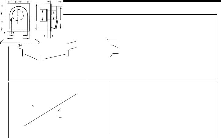
Figure 2 CURB FOR ROOF
|
|
|
|
|
|
2" |
|
|
5-1/2" |
||
|
|
|
|
|
|
|
|
|
|
|
|
|
|
|
|
|
|
|
|
|
|||
|
20 |
-3/4" |
28" |
||
|
|
||||
|
|
|
|||
|
|
|
|||
|
|
|
|
||
Figure 3 |
|
|
|
|
|
|
|
|
Figure 4 |
|||
|
|
|
|
|
|
|
|
|
|
|
|
|
AElbow |
|
|
|
|
|
|
|
|
A Elbow |
|
|
|
|
|
|
|
|
|
|
|
|
|
|||
|
|
|
|
|
|
|
|
|
|
|||
|
|
|
|
|
|
|
|
|||||
|
|
|
|
|
|
|
||||||
|
|
|
|
|
|
|||||||
|
|
|
|
|
|
|
|
|
||||
|
|
|
|
|
|
|
|
|
|
|||
B Round |
|
|
|
|
|
|
|
|
||||
|
|
|
|
|
|
|
|
|||||
|
|
|
|
|
|
|
||||||
|
|
|
|
|
|
|
||||||
Duct |
Roof |
|
Transition |
|
|
|||||||
Roof |
|
|
|
|
|
|
|
|
|
|
||
Transition |
|
|
|
|
|
|
|
|
|
|
|
Outside |
|
|
|
|
|
|
|
|
|
|
|
|
Wall |
|
|
|
|
|
|
|
|
|
|
|
|
|
|
|
|
|
|
|
|
|
|
|
|
|
|
Figure 5 |
Figure 6 – Remote Blower Dimensions |
|
|
|
A Adjustable Elbow |
|
|
|
|
|
|
I |
|
|
||
|
|
|
|
|
|
|
|
|
|
|
|
|
|
|
|
|
|
|
|
|
|
|
|
|
|
|
|
||
|
|
|
|
Tape Joints |
|
|
|
|
|
|
|
|
|
|
|
|
|
|
|
|
|
|
|
|
|
|
|
||
|
|
|
|
|
|
|
|
|
|
|
|
|
||
|
Conduit |
|
|
B Dia. Duct Conduit |
|
|
|
|
|
|
|
|
|
|
(Not Provided) |
|
|
|
|
|
|
|
|
|
|
|
|
|
|
|
|
TYPICAL INSTALLATION USING THERMADOR HOODS |
|
|
|
|
|
|||||||
|
|
|
|
|
|
|
|
|
|
|
|
|
||
|
|
|
|
|
|
|
|
|
|
|
|
|||
MODEL |
A |
B |
C |
D |
E |
F |
G |
H |
|
I |
J |
|||
VTR1000Q |
10" Dia. |
10" Dia. |
10-3/4 |
10-1/4 |
3-1/8 |
17-5/8 |
10-3/4 |
10 |
26-1/4 |
4 |
||||
VTR1400Q |
10" Dia. |
10" Dia. |
10-3/4 |
10-1/4 |
3-1/8 |
17-5/8 |
10-3/4 |
10 |
26-1/4 |
4 |
||||
VTR600R |
8" Dia. |
8" Dia. |
10-3/8 |
11-1/2 |
4-5/8 |
14-7/8 |
8-3/4 |
8 |
24 |
3-1/2 |
||||
NOTE: The unit must be sealed between the roof (or wall) and the underside of the flange with roofing mastic to prevent leaks. For installation on a flat roof, or roofs with a pitch less than 1-1/2" in 12", install ventilator on the curb as shown in Fig. 2. Position the curb on flat roofs so that the discharge (low) end points away from prevailing wind.
3.Connect ventilator to the exhaust system with 8 inch dia. duct for VTR600R and 10" dia. duct for VTR1000Q and VTR1400Q. Use adjustable elbow to adjust to roof angle. Tape all joints to prevent air leaks.
4.Connect ducting in the inlet to the ventilator with duct tape.
5.Clearance to combustible material is 0".
II.FOR WIRING TO ALL APPROVED THERMADOR® PRODUCTS, USE INSTALLATION INSTRUCTIONS PROVIDED WITH THAT PRODUCT.
III.WIRING TO A WALL MOUNT 4 POSITION VENTILATOR SPEED CONTROL SWITCH:
1.Use Thermador 4 position ventilator speed control model CTR3Q (purchased separately).
2.Power supply required for these ventilators is
15 amps. @120V. AC, 60 Hz. connected per local codes.
3.Run three (3) #14 AWG. wires (black, white and green) from the power supply at the electrical circuit panel to the wall box. See Figure 8.
4.Run electrical conduit per local code to conduit outlet in bottom of ventilator as shown in Fig. 5. Other end of conduit will connect to wall box with 4 position switch. See Figure 8.
5.Run five (5) #14 AWG. wires in conduit between Ventilator J-box and 4 position switch. Use color coded wire corresponding to colors shown in Figure 8.
6.Use wire nuts to connect wires as shown in Figure 8.
2
 Loading...