

Page 1

Commercial Computer Systems
General Information
'IEXt\S
INSIRUMENTS.
Page 2
DS990
Commercial
Computer Systems
General Information
~
~
TEXAS
Published by
INSTRUMENTS
INCORPORATED
Page 3
Copyright@
Reserved. Printed
19-7-8-by Texas Instruments
in
the
United States
of
America.
incorporated.
AItRrghts
No part
system,
mechanical, photocopying, recording,
written permission
Texas Instruments reserves
improve design and supply
The information
and should
I ncorporated. Texas Instruments assumes no responsibility for any
errors
of
this publication may be reproduced, stored
or
that
may appear
transmitted
in
not
be construed as a
in
any form
of
Texas Instruments Incorporated.
the
the
best
this
document
in
this
document.
1st Edition,
Texas Instruments Incorporated
Digital Systems Division
P.O. Box
Austin, Texas 78767
or
or
right
to
product
is
subject
commitment
July
2909
otherwise,
make changes
1978
in
a retrieval
by any means, electronic,
without
possible.
to
change
by Texas Instruments
the
at
any time
without
prior
to
notice
Page 4
Table
of
Contents
OS990 Commerciai Systems Overview
DS990 Software
DX10 Operating
File Management
Error
High-Level
Program-Development Tools
Communications Software
DS990 Hardware
990 Processor. . . . . . . . . . . . . . . . . . . . . . . . . . .
TILINE
CRU Peripherals
Communications Equipment and Special
nterface
I
990
Chassis
Customer-Support Services
D X 1 0 Operati
System Generation
Program Management
Memory Management
System Command Interpreter
File Management
File Types
File Features
Physical Disk Characteristics
Logical
Error
Control
High-Level
COBOL
RPG
DBMS 990
BASIC
FORTRAN
Pascal
Sort/Merge. . . . . . . . . . . . . . . . . . . . . . . . . . . . .
Program-Development Tools
Interactive
Macro Assembler
Link Editor
Debug
Communications Software
Features
Comparison with
Control
System Requirements
Components
Customer
............................
System
.....................
..........................
Control and System Log
Languages
............................
Peripherals
Devices
.......................
.........................
..........................
Considerations
08990
ng
System. . . . . . . . . . . . . . . . . . . . . . .7
........................
.......................
......................
...........................
.............................
...........................
Input/Output
and
Languages
...............................
II
...............
.............................
.............
............................
................................
Text
Package
of
3780 Emulator
...............................
Information
......................
System Log
and Utilities
Editor.
.........................
............................
..........................
IBM 3780
......................
of
3780 Emulator
.................
and Utilities
..................
..................
...................
.....................
Software
................
............•....
..................
...............
"
......
"
.................
...................
....................
....................
..................
..................
...............
.....................
..............
" "
....
Page
.4
.4
.4
.4
Page
10
10
13
13
13
15
15
16
17
17
20
21
22
27
29
31
31
31
31
32
32
32
33
33
34
34
34
35
DS990 Hardware
Page
2
2
2
3
3
3
4
5
5
5
8
8
990 Processor
990 Architecture
Interrupt Structure
990 Address
Instruction Set
990
Programmer
990 Memories
990
Communications Register
TI
LINE
Model
Model
Model DS25 and Model DS50 Disk System
Model 979A Magnetic-Tape Transport
CRU Peripherals
Model
Model
Model 2230 and Model 2260 Line Printers
Model 733 ASR Data Terminal
Model 743 KSR Data Terminal
Model
Model
Communications Equipment
Special Interface Devices
EIA
TTL
TTY
32-Bit Input!Transition Detection Module
32-Bit Output-Data Module
Digital-I/O-Termination-Panel Module
D/A
A/D
990
Chassis
Standard
Dc-Power Considerations
CRU and
.............................
.........................
......................
Space
........................
and Addressing Modes
CPU
On-Board Loader
Panel
........................
...........................
TILINE
............................
Peripherals
DS31
OSlO Disk System
911
810 Printer
804 Card Reader
FD800 Floppy-Disk System
Data Modules
Data Modules
/EIA
Converter Modules
Converter Modules
.........................
Disk System
...........................
Video Display Terminal
........................
........................
........................
Terminal Interface Module
Considerations
Chassis
Configuration in DS990 Systems
TILINE
I/O
..................
Unit
...................
..................
....................
...................
......................
..................
....................
....................
....................
...................
Expansion
................
...............
....•..........
..............
...........
....•...
....•......
.............
........
.............
.......•...
........
...........
...
37
39
.40
40
41
42
42
42
43
43
43
44
.45
46
47
47
47
50
50
51
52
52
52
53
54
54
54
54
54
54
55
55
55
55
56
56
57
Customer-Support Services
Page
Hardware Installation
Software
Hardware Maintenance
Maintenance Agreement
Software Update
Education
Customer-Support Line
Installation
On-Call Service . . . . . . . . . . . . . . . . . . . . . . . . . . 60
Fixed-Price Repair Service
Classes
........................
........................
.•.....................
......................
...................
...........................
..........................
(Hot
Line)
..............•
59
59
59
59
61
61
62
62
Page 5
Appendixes
A!'pendix
A
SC
I Commands
B 990 Instruction
C Memory Requirements
o Recommended Memory
E Disk Requirements
F
Chassis
Chassis-Power
Chassis-Layout Planning
G Cabinet Planning
Enclosures
Cabinet-Layout Worksheet
H DS990 System
I Equipment Specifications
J Packing
K Documentation. . . . . . . . . . . . . . . . . . . . . . . . 83
Hardware Manuals
Software Manuals
Figure
DS990 Model 4
System
2 Memory Conservation through Disk
Management
3 Example
of
a Disk Volume
4 Custom Procedure Example. . . . . . . . . . . . . . . . 12
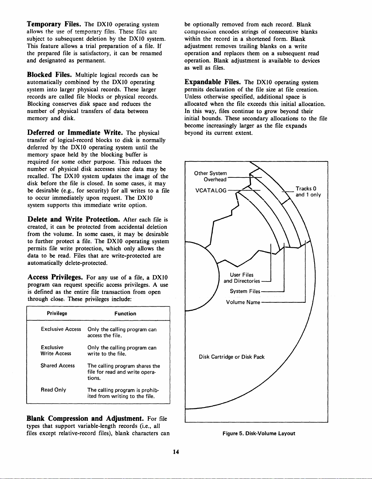
5 Disk-Volume Layout
6 Files and Directory Structure
7 Multiuser
8
Pascal
Programming Cycle
9
Pascal
10 Typical Application
t 1 DS990 Standard
12 Workspace Pointer
13 990
14 Model
-15
16 Model OSlO Disk System
1 7 Model DS25/DS50 Disk
18 Model 979A Magnetic-Tape Transport
19 Model
20
21
22 Model 810 Printer
23 Model 2230
24 Model 733 ASR
25
26
27 Model
28
29 Model 990/10 Minicomputer
30 Model 990/10 Minicomputer Thirteen-Slot
31
32 Standard
33 DS990 Enclosures
34 Dimensional
Block Structure
Distributed-Processing Environment
CPU
Map
Option
-1)531
CbhfrolJerwfth-Follrtflsidlrives":
Basic
VDT
Model
Model 743
Model 804 Card
990 Communications Modules
Chassis
Standard 990
"Quietized"
........................
Set
.....................
...................
and
Disk Configurations
.....................
Planning
DS31
911
911
FD800 Floppy-Disk System
.......................
Planning
.................
................
.......................
.........................
Kit
Contents
.................
and
Shipping
..............................
of
the
BASIC Components
rr
I
LIN E Address
Video Display Terminal.
Kit
Keyboard
and
KSR
.............................
Chassis
....................
....................
....................
List
of
Illustrations
System
and
Model 6
..........................
Menus
for
Initialization
......................
....................
............•....
...................
of
3780 Emulator in
and
Optional Hardware . . . . . . • 38
and
Registers
................•.........
Disk System
....................•...
Model 2260 Line Printers
Data
Data Terminal
Reader
Chassis
Layout
Outline
Pedestal
Space
................
...........•....
System
..................•.
......................
Terminal
. ... . . . . . . . . . . . . . . . 52
Configuration Chart
..................
......................
of
Model DS10 Disk
....................
..............
...............
.............•.
..............
.............
.............
.............
..............
...............
or
..........
............
with
.........
..........
...........
Model 8
.:~-.
......
......
on
. . .
Page
..
Page
63
63
63
70
71
71
72
73
75
75
79
81
81
81
83
84
23
30
31
32
39
40
.44
.4-5
.45
46
47
48
48
49
50
51
52
52
53
53
55
56
56
77
78
79
10
11
14
15
35 Dimensional Outline
Pedestal
.............................
36 Cabinet-Layout Worksheet
37 Minimum Equipment Spacing
DS990
Systems
38
DS990 Desk-System Packing Crate
39 Exploded View
40 Exploded View
41
42 Typical Pedestal-Mounted-Disk-Drive Shipping
Th~
1
2 Device
3 Relative Power
4
5 BASIC
6
7
8
1
9
Crate
Packing
Crate
Packing
Typical Rack-Mounted-Disk-Drive Shipping
Configuration
Configuration
Areas
Served
and
Supervisor
RPG
BASIC Matrix Statements
BASIC
Functions
Conditional Relations
Operating Commands for
File Operations Available through 1/0
Calls.
II Enhancements
and
Business
and
Business
...........................
of
DS25
........................
of
Single-Bay-Desk
.........................
of
Double-Bay-Desk
.........................
.........................
.........................
List
of
Tables
by DX10
SCI
. . . . . . . . . . . . . . . . . . . . . . .
of
COBOL.
...................
BASIC Statements
.................
BASIC Intrinsic
for
BASIC
BASIC
10
..............................
Types
Hardware Configuration
11
3780 Emulator
Hardware Configuration
12
3780 Emulator
Maintenance-Agreement
13
14
On-Call
SCI
15
16
17
18
19
20
21
22
23
24
25
26
27
28
29
30
31
32
33
34
35
36
37
Command Index
990 Instruction
DX10 Memory-Estimating Form
Recommended Software-Development
Configurations
Recommended Application-System
Configurations
Disk-Pack
DX10
So~~~e~i~Els.~.~.
Software-Development Disk Requirements
Chassis
Blank
990-Chassis
Blank
CRUrrlLlNE
Layout Form
Basic
DS990 System
DS990 Model 4 System Consolidated
Parts
List. . . . . . . . . . . . . . . . . . . . . . . . . . . . 83
DS990 Model 6 and Model 8
Consolidated
DS990 Model 4 Commercial Consol idated
Parts
List
DS990 Model
System Consolidated
DS990
HardwarelSoftware Versions
DS990
Hardware-Only Versions
Optional DS990 Software, Object Format
DS990 Hardware Options
Standard
Hardware Manuals
Software
........................
........................
Service
......................•.
........................
........................
Sizes
........................
Planning Form
.........................
Parts
.•..........................
6
Basic
Software-Package Contents
Basic
Software-Package Contents
DS990 Equipment Specifications
Manuals
for
for
Service
......•.....•.......
Set
.....................
~."~
...................
Layout Form
Expansion-ChassiS
Kit
Configurations
List
...................
and
Model 8 Commercial
Parts
..................
...............•.
.....................•
.....................
or DS50 Disk
................
for
...........
Commands
................
............
............
DX10
TX990
.............
............
.. ' .. ' ..... , .......••
.............
Systems
List
.............
............•..
........
........
......
........
for
for
......
on
.....
79
80
84
85
86
87
88
89
~e
12
16
17
21
24
24
25
25
26
28
34
35
60
60
65
67
68
70
71
71
L
•••
11
72
73
75
76
82
90
90
90
91
92
92
93
94
99
100
Page 6
DS990
Commercial
Systems
Overview
The Model
shown in figure
Model
DXI0 disk-based commercial operating system. The
systems are specifically designed for commercial,
interactive, multiuser, multitasking, multilanguage,
and communications applications.
The models differ in disk-file capacity to provide
an
orderly growth path. The Model 4 System
10M-byte disk-based system suitable for a small
software-development system or medium-scale
application system. The Model 6 System
25M-byte disk-based system suitable for mediumscale software-development and application systems.
The Model 8 System
system intended for medium- to large-scale softwaredevelopment and application systems. Physical
packaging differences between the three models are
based on the space requirements of the disk-storage
units.
The base systems are offered in the minimum
configurations that support the full functions
operating system. This allows maximum flexibility in
adding optional software and hardware features to
customize a system. The various models are available
in either equipment-only versions or in versions that
include system software and installation. Software-
included versions provide a licensed copy of the
DX
10
facilities, documentation, and a one-year software
SUbscription service for the
provided sysgen
include software. Systems are configured and tested
before they are shipped from the factory.
4,
Model
990/10 Minicomputer with the power
operating system and software-development
6,
and Model 8 Systems,
1,
combine the performance
is
is
a dual
is
also installed on systems that
SOM-byte
DXI0 system. A factory-
disk-based
of
the
of
the
is
a dual
of
a
the
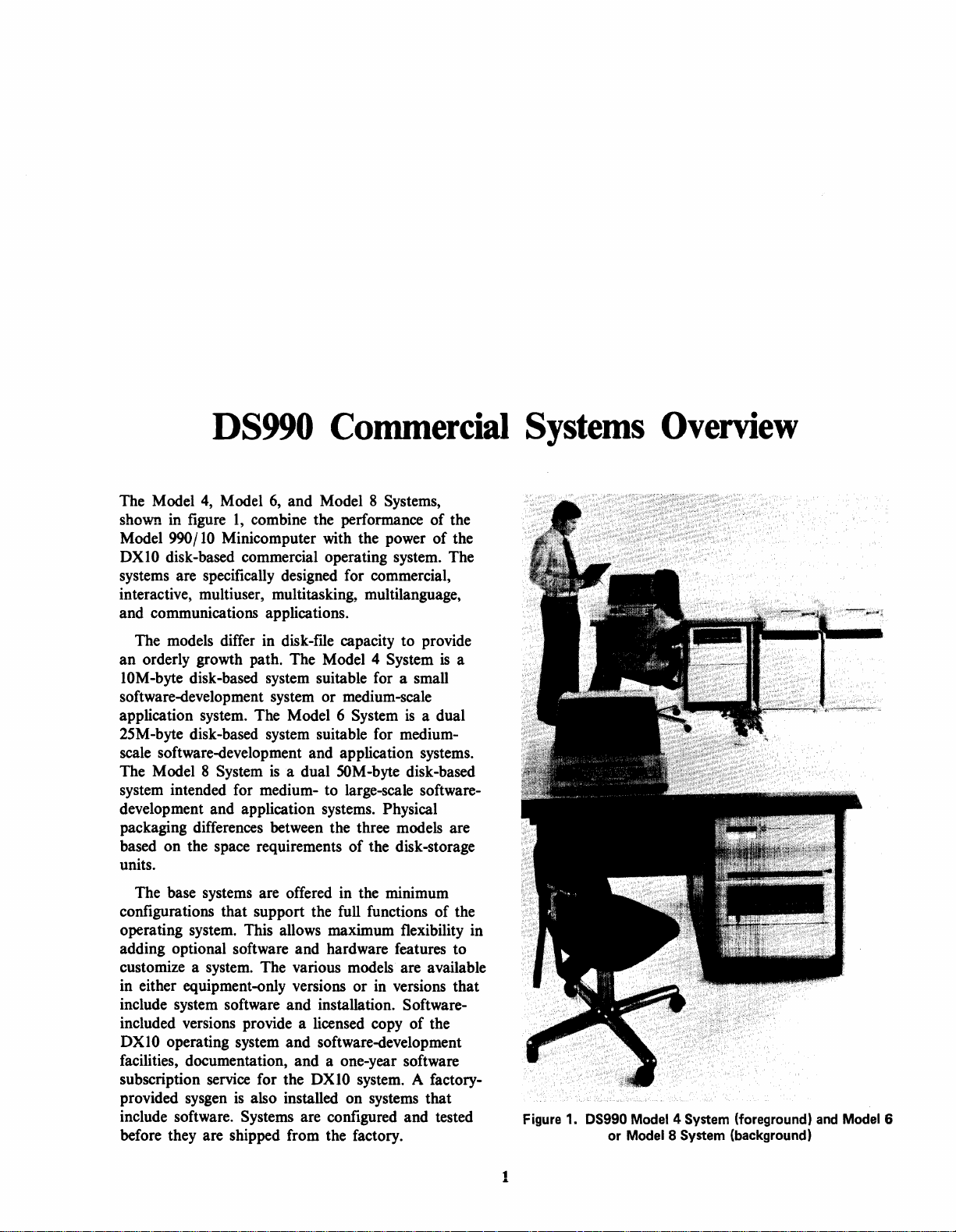
Figure 1. OS990 Model 4 System (foreground)
or
Model 8 System (background)
and
Model 6
1
Page 7
DS990
DS990 software
comprehends user requirements in a way not found
in most computers
Operators interface with the
through Model
that provide hierarchical menus with supporting fillin-the-blank, prompting, and predefined functions.
More than
commands provide powerful and comprehensive
system control.
commands that reflect their application terminology.
A broad range
are built into the system-command structure.
Program memory
Resource management
location roll in/roll out and task-level priority
assignment.
The
management. Types of
sequentiai, reiative-record, and muitikey-indexed
The key-indexed method supports a unique real-time,
self-maintenance capability.
Software
is
both versatile and efficient.
of
this class.
DXIO
DXIO operating system has flexible
Operating System
DXIO
operating system
911
Video Display Terminals (VDTs)
170
Texas Instruments-supplied system
Users can also provide custom
of
utilities and supporting routines
is
dynamically allocated.
is
enhanced by variable-
files
supported include
It
file
files.
Program and Memory Management. The
DXIO operating system
system.
the
procedures, and overlays. Programs are installed and
stored in program
activated, its images are loaded into any available
memory area.
several different locations in memory by the
operating system several times during its execution
to efficiently share memory and processor resources.
When in memory and active, a program competes
with other programs for execution time on a userdefined priority basis. When a program terminates,
the operating system releases all program-owned
resources including files, devices, and memory. This
unique
a memory-mapping technique. These advanced
memory- and program-management techniques
provide high processor utilization, resulting in high
levels
User programs that operate under control of
OX 1 0 system include a composite of tasks,
An active program can
DXIO program structure
of
throughput.
is
a mUltiprogramming
files.
When a program
be rolled in and out of
is
DXIO
is
made possible by
System Command Interpreter. Operators
DXIO
interface with the
VDTs via the system command interpreter (SCI).
The SCI
that provide system functions ranging from setting
is
a collection of more than
operating system through
170
procedures
the time of day or initiating compiles to backing up
disks. Commands are
the SCI. This can save
development effort on major programs. The
completeness and flexibility
performed by the SCI make it without parallel in
the minicomputer market. Many
performed
machines.
Activation
command menus made available to all types
system terminals. The command menus provide each
terminal on-line command prompts by logical
grouping.
Custom commands can
framework
combine SCI primitives with their own application
language to provide a user interface that
to the terminology and customary procedures of the
application.
Interactive Operation. The DXIO operating system
features an excellent interactive user interface for
control of the system through SCI.
by an operator are
are easily edited
the system. The number of prompts, and therefore
time, can
command can
them by prompt. When a partial list
entered, any arguments not already supplied
operator or default specified are then prompted.
Batch Operation. The background program
terminal may
SCI
(batch processing). Batch input
sequentially oriented
terminal itself. An
processing, query its status, and receive information
concerning its normal or abnormal completion.
Certain interactive commands are inappropriate for
batch operation, but all other SCI commands are
available.
by
the SCI are found only on main-frame
of
of
the DXIO operating system. Users can
be conserved since all arguments for a
be entered before the system requests
be
is
interpreting commands in the background
at
the operator's fingertips via
10
to
30
percent of
of
the functions
of
the functions
SCI commands
ffieaningfuHy
by
the operator and are verified
a copy of the SCI. In this case, the
file
device but not from the
operator can initiate batch
is
via a hierarchy
of
be integrated into the
is
unique
All
entries keyed
prompted. Fieids
of
arguments
by
at
is
from any
the
the
of
by
File Management
The
DXIO
operating system provides a filemanagement package that includes a complete range
of
file
structures and features. The
accommodate many uniquely named data
disk cartridge and provides the necessary
management for allocation of disk space to the
The user can specify the amount of space to be
allocated to a
that space
as
it
is
needed.
is
file
or, more frequently, can specify
to
be
automatically allocated to the
DXIO
system can
files
on a
files.
file
is
2
Page 8
File Types. Three major
by
the DXI0 operating system: sequential, relativerecord, and multikey-indexed
allow records with concurrent reads. Relative-record
files
provide rapid access to fixed-length records in
either random or sequential mode. In multikeyindexed
providing the
to fourteen
keys
data addressed by the
maintenance capability. Deleted or added keys are
automatically removed or inserted in the sorted
lists. The DX
contracts the
necessity for periodically rebuilding and reorganizing
files.
files,
variable-length records are accessed by
DXI0 operating system
keys
by
which the data
are in sorted order and allow rapid access to
rvtultikey indexing provides a unique self-
10
system automatically expands or
key
lists and eliminates much of the
keys.
file
types are supported
files.
Sequential
anyone
is
known. The
files
of up
key
Instruments version of
oriented and provides one-line-at-a-time forms or
multiline listings.
Texas Instruments
base management system specifically designed for
minicomputer applications.
data-definition language (DDL) for defining the
logical structure of data and a data-manipulation
language (DML) that interfaces through
storing and retrieving data. A number
and security features can optionally
the modular structure of
The BASIC** language
BASIC
Kemmeny and Kurtz, with certain extensions to
enhance its
type, expanded string handling, CALL, and
subprograms.
as
described in BASIC Programming, by
use.
RPG II
DBMS
The extensions are integer arithmetic
is
video-display-
990
is
a modular data-
DBMS
DBMS
is
990
includes a
COBOL for
of
utilities
be used within
990.
a version of Dartmouth
File Features. Various
are available to the assembly-language user. Highlevel
languages
given feature, depending on the syntax of the
language.
• Record locking
• Temporary
• Blocked
• Deferred or immediate write operation
• Delete and write protection
•
Access
• Blank compression and adjustment
• Expandable
• Blank compression.
mayor
Some of the supported features include:
files
files
privileges
files
file
features and
may not allow access to any
file
types
Error Control and System Log
The DXI0 operating system incorporates several
error-control features and supports an optional
log.
The
990
system
OX 1 0 system from destruction
programs. An optional end-action routine analyzes
abnormal termination and takes appropriate
steps.
mapping feature protects the
by
errant application
recovery
High-Level Languages and Utilities
COBOL, RPG II, DBMS
BASIC, FORTRAN, Pascal, and Sort/Merge
packages are available as options on all DS990
systems.
The
COBOL compiler conforms to the American
National
(ED lX3.23-1974) and incorporates extensions to this
subset to provide added capabilities.
The
System/3* RPG II specifications with certain
equipment and teleprocessing exceptions. Texas
Standards Institute (ANSI) COBOL subset
RPG II compiler conforms to the IBM
990,
BASIC, Business
BASIC
BASIC, a variation
understood, business-oriented, application-solving
language. Single-key-indexed
and limited-output editing capabilities are included to
provide a check-printing capability.
The FORTRAN compiler conforms to the ANSI
standard FORTRAN, or FORTRAN
compiler also incorporates the extensions
recommended by the Instrument
(lSA-S61.1,
Pascal
for a variety
language for teaching a systematic concept
programming, Pascal
use.
to
useful when programs must
other than the original author.
The
comprehensive
accessed in several ways. SCI provides commands to
access
COBOL,
programs can interface with Sort/ Merge by using the
CALL statement. Both sort and merge processes
support record selection, reformatting on input, and
summarizing on output. Ascending key order,
descending
sequence can be specified.
is
aimed
is
a general-purpose language well suited
Its readability makes the language especially
DXI0 operating system supports a
Sort/ Merge in batch or interactive mode.
RPG
key
at
the scientific user. Business
of
BASIC,
1975
and ISA-61.2,
of
applications. Originally designed as a
is
straightforward to learn and
Sort/ Merge package that can
II, FORTRAN, and BASIC
order, or an alternate collating
is
an easily
file
input/ output (I/O)
IV.
Society of America
1976).
be maintained
The
of
by
users
be
Program-Development Tools
In addition to a comprehensive set
operate in conjunction with the
*IBM System!3 is a registered trademark of IBM.
**BASIC
is
a registered trademark of Dartmouth College.
of
utilities that
DXI0 operating
3
Page 9
system, Texas Instruments provides four
program-development tools: interactive text editor,
macro
Each
invoked by
assembler, link editor,
of
these operates
operator
under
commands.
and
SCI
major
debug package.
and
is
easily
Communications Software
The
OXI0
of
commercial systems with a means
entry
host
990 computer.
Communications Terminal
systems so equipped
as central
network. Optional auto-call capability is also
provided.
point-to-point
up
to
specified
support
communications interface module
supplied modem
modem kit
3780
Emulator
(RJE)
computer
communications with
or
another
Operation
can
or
satellite stations in a distributed
Oata
files are transmitted over leased
or
switched telephone lines
9600 baud. Any file
to
transmit
of
3780 emulation
and
or
or
Texas-Instruments-supplied
optional auto-call unit.
provides the OS99O family
of
remote-job-
an
IBM
360/370
3780 emulator-equipped
of
the IBM 3780
is
emulated. OS990
operate in unattended mode
or
system device
receive data. Hardware
is
provided with the 990
to
Oata
at
speeds
can
a customer-
be
DS990 Hardware
The DS990 disk-based systems require a fast, flexible
computer
demands
Model 4, Model 6,
on
random-access-memory
processor features the
speed
that
memory.
AU-models employ
at
least one removable disk pack
fixed
backup,
important
Each system includes one 1920-character video
display terminal
controller
a second VDT. Additional VDTs are available
options.
The
memory-to-memory architecture
asynchronous, high-speed
offer main-memory capacities up
metal-oxide-semiconductor (MOS), 16K dynamic-
*TILINE
architecture
of
multiple interactive operations.
a minimum 128K-byte 990 processor with 16K
data
bus
allows addressing
or
removable disk pack. This allows copy,
and
transportability
in interactive systems.
is
included
to
meet the processing
and
Model 8 Systems are based
(RAM)
TILINE·
and
a memory-mapping technique
of
moving...Jtead-
and
keyboard. A dual-terminal
and
technology.
asynchronous, high-
up
to
2048K bytes
disk drives with
and
one additional
of
media
allows the easy addition
that
The
The
of
are
main
so
as
990 Processor
128K-byte 990 processor features
data
bus.
is
a registered trademark
of
Texas Instruments.
and
TILINE
Current
to
384K bytes
an
advanced
models
of
of
RAM,
The additional
module sizes.
is recommended for these memory modules. Memory
can
options.
system, a high-speed, asynchronous parallel
bus,
communications register unit
error-checking-and-correcting (ECC) memory.
ECC
memory is available in various
TILINE
be further expanded by adding
The
990 processor includes a dual
and
a low-
expansion
to
medium-speed command-driven
(CR
to
a second chassis
standard
input/
U).
990
output
TILINE
TILINE Peripherals
TILINE
which transfer
rates
the 990 computer.
The
following disk systems, depending
selected. The
cartridge with 2.8M bytes
This disk drive
Model 8 Systems.
and
type disk cartridge. Each platter has a 4.7M-byte
capacity
bytes. This
System
4
6
and
can
pack with 22.3M bytes
DS25 disk drives are employed
System.
up
pack with 44.6M bytes
OS50 disk drives are employed
System.
up
optional
available:
format
format. Both versions use industry-compatible, nine-
track
millimetres
peripherals are high-speed
data
to
and
from 990 memory
that
approach
DS990 base system includes one
The OSlO Oisk System has a single-spindle, fixed-
femovabie-piaUer disk drive employing the 5440-
for
a combined disk-drive capacity
is
and
Model 8 Systems. One
accommodate
The
DS25 Disk System has a multiplatter disk
One
to
four DS25 disk drives.
The
. DS50
..
One
to
four DS50 disk drives.
The
Model 979A Magnetic-Tape
TILINE
an
and
a 1600-bits-per-inch, phase-encoded
tape
formats.
per
the
instruction execution rate
DS31 Disk System has a 2315-type disk
of
is
an
option
the disk drive supplied with the Model
is
offered as
up
OS25 disk controller can accommodate
Disk. System
OS50 disk controller can accommodate
peripheral. Two versions are
8OO-bits-per-inch, nonreturn-to-zero
The
second (37.5 inches
an
to two
of
formatted capacity.
..
has.amllltiplatter·
of
formatted capacity.
transport
I/O
systems
of
the
on
the model
formatted capacity.
on
the Model 6
option
DS
DS
on
I 0 disk controller
I 0 disk drives.
on
the Model 6
on
the Model 8
Transport
operates
per
and
of
the Model
disk
at
second).
at
9.4M
Dual
Dual
is
an
953
of
CRU Peripherals
The command-driven communications-register-unit
(CRU)
systems
processor. These peripherals are optional features
that
peripherals are low-
that
transfer
further enhance the DS990 system.
data
to
medium-speed
to
and/
or
from the 990
I/O
4
Page 10
The Model
9 x 7 dot-matrix character structure and a ninetysix-character, full
810
printer prints 132-column lines at
per second with eight-channel vertical-format control.
The Model
print 136-column
600
lines per minute, respectively, with verticalformat control, internal self-test, static eliminator,
and standard
Additional Model
are available
keyboards and interfaces. A maximum of
VDTs can
two-chassis configuration. Additional VDTs can
installed in other vacant slots
interrupt assignments. VDTs can also
add-on chassis.
The Model
minute reader that takes standard-sized, eightycolumn punched or marked cards.
Silent 700· Model
The
KSR Data Terminals
solid-state, thermal printheads for virtually silent
printing of eighty-column lines at thirty characters
per second. A typewriter-style, limited
keyboard allows operator entries.
The Model
transportable diskette media to smaller members of
990
the
810
Printer
ASCII, compressed print set. The
2230
lines
ASCII, sixty-four-character set.
as
single- or duai-terminal displays with
be
installed in their predefined slots in a
804
Card Reader
FD800 Floppy-Disk System provides
family of systems.
is
an impact printer with
and Model
at
911
use
2260
Line Printers
300
lines per minute and
Video Display Terminals
by
redefining the
is
a 400-card-per-
733
ASR and Model
Texas Instruments unique
be
150
characters
twelve
installed in
ASCII
be
743
Communications Equipment
and
Special Interface Devices
Optional communications equipment includes an RS232-C
communications interface module for
asynchronous and synchronous transmission at
75
to
9600.
selectable baud rates from
supporting options include asynchronous and
synchronous modems and auto-call. A variety of
interface modules for custom-device interface or
process monitoring and control are available
including analog-to-digital converters and digital
input and output interfaces. A variety of
Teletypewriter / Electronics Industries Association
(TrY
/ EIA) interfaces are also available.
Other
990 Chassis Considerations
The
990
computer
chassis with a programmer panel. The chassis
includes a
read-only memory (ROM).
be
added to the system to provide additional
mounting space or dc power.
4O-ampere
is
packaged in a thirteen-slot
power supply and a disk-loader
One or more chassis can
Customer-Support Services
Texas Instruments customer services encompass the
following areas: hardware installation, software
installation, hardware maintenance, software update,
line.
education classes, and telephone hot
be
services can
customer requirements.
selected to best suit application and
Individual
·Silent
700
is
a registered trademark of Texas Instruments.
s
Page 11

6
Page 12
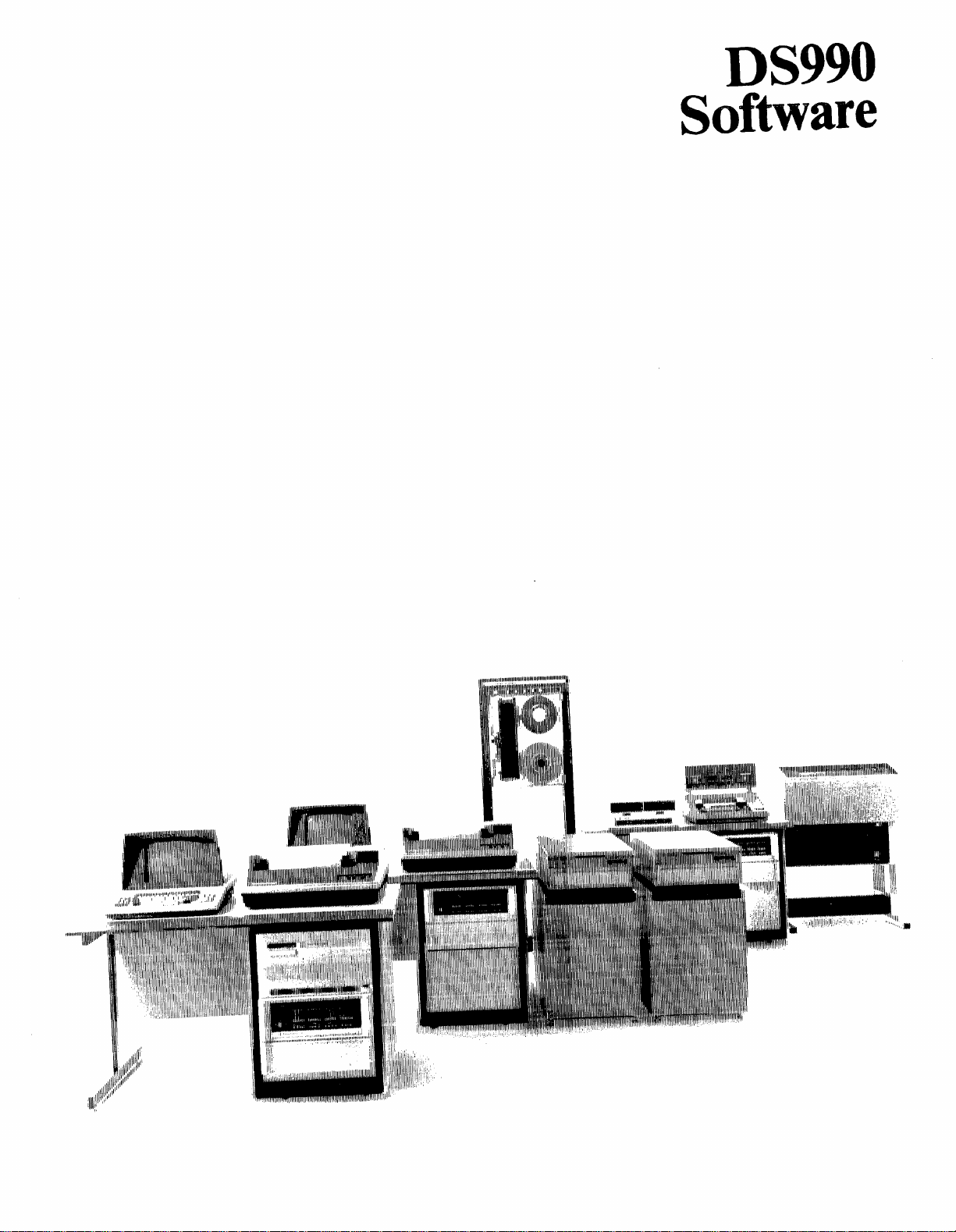
DS990
Software
Page 13

Page 14
DS990 Software
DS990 software features a versatile and powerful
operating system, the DX
management and error-control features make this
operating system an extremely efficient one. A wide
variety of high-level languages are available with the
DS990 system. Among these are COBOL,
DXIO
The operating-system software selected for a
computer installation has a major effect on the
throughput, reliability, and usability of the system.
The disks, processors, memories, terminals, and other
physical resources of a computer system represent a
potential for performance. The operating system
controls the total system resources and allocates
them to the various tasks required in the user's
application programs. An operating system also
provides other necessary system services and utilities,
such as interrupt handling and input/ output (I/O)
device service routines. The operating system relieves
the individual application program of these overhead
responsibilities, which greatly reduces the opportunity
for error and simplifies application programming.
The
powerful disk-based operating system; it
the most sophisticated, flexible, and versatile
computer operating systems available. First released
1976,
in
has been refined
Instruments and
Operating
DXIO
operating system
the
DXIO
by
at
10
operating system. File-
System
is
Texas Instruments
is
one of
system
customer sites around the world.
is
a proven product that
operation within Texas
FORTRAN, RPG II, BASIC, Pascal, and DBMS
990.
Software-development tools include an
interactive text editor, macro assembler, link editor,
and debug package. These features enable DS990
software to comprehend user requirements in a way
not found in most computers of this class.
DXIO
The
of program-development utilities, which greatly
reduces development time and improves effectiveness.
Programs can
operating system to execute on the DS990 system or
on the smaller floppy-disk-based or memory-resident
systems in the
packages are sold as extra-cost options to many
operating systems; however, they are included as part
of the DX
a major application of the DS990 systems. The
program-development utilities include an interactive
text editor, relocatable macro assembler, link editor,
and interactive debugger.
Many users prefer to write programs in one or
of
more
languages. Compilers / interpreters for FORTRAN
(with Instrument Society of America (ISA) processcontrol extensions), COBOL, BASIC, Business
BASIC,
available as optional features of the DXI0 operating
system.
operating system incorporates a number
be
developed under the
990
family. Program-development
10
system because program development
the major high-level programming
RPG II, DBMS 990, and Pascal are
DXIO
is
The
DXIO
system
multitasking operating system, which
multiterminal interactive operations. The operating
system makes each terminal appear to have exclusive
control of the system; so the existence of other
is
terminals
Batch-processing tasks can
terminal without interfering with interactive terminal
operations.
The
management capabilities. The
files, allocates disk and memory space for
transfers
and controls read access, write access, deletion, and
file
sharing by
supports sequential files, relative-record
multikey-indexed
transparent to any individual user.
DXIO
operating system has extensive file-
files
between disk and memory as required,
is
mUltiple
files
a general-purpose,
is
optimized for
be
initiated from any
DXIO
system creates
files,
users. The operating system
files,
and
with up to fourteen
keys.
The
DXIO
operating system includes the device
service routines necessary to communicate with the
standard and optional DS990
the Model
disk systems, Model
Model
Tape Transport, and
device
system. The
further isolates an individual user program from the
characteristics of the
an
I/O
referenced by a logical unit number (LUNO).
This simplification allows the user to concentrate
on the application problem rather than on device
details. Logical
program development in which a
7
911
Video Display Terminals (VDTs),
810
2260
Line Printers, Model
Silent
service routines can
DXIO
system
I/O
device to
be
I/O
is
treated as a
particularly useful for
110 devices, such as
Printers, Model
979
A Magnetic-
700
terminals. Special
be
linked to the
uses
logical
device. Logical
file
that
file
or another
1/0,
2230
I/O
is
and
DXIO
which
allows
I/O
Page 15
device
can
be substituted for the device
ultimately
A versatile, interactive, fully prompted system
command interpreter (SCI) allows direct
communication between the operating system
user. This powerful command interpreter
convenience
The
operating system
customer's site. Customizing the operating system
improves the efficiency
interactive system-generation (sysgen) program
supplied with the DXIO system
convenient means
system.
To
customers' interests, the
only available
includes software updates for one year following
purchase with
(The software sUbscription service
users who allow their subscriptions
decide
license also includes installation support (basic
system generation
Instruments customer engineer.
information, refer
be used.
of
the DXIO system.
DXIO operating system
that
can be customized for each
of
of
implementing the custom
protect Texas Instruments investment
on
a licensed basis. The license
annual
to
update their systems.) The DXIO software
renewal subscriptions available.
and
verification) by a Texas
to
the
is
a modular
resource utilization. An
to
DXIO operating system
For
990
Computer Family Price
that
will
and
is
a major
provide a fast
and
is
also available
to
lapse
and
additional
is
List.
the
and
its
is
then
for DS990 Model 4 Systems, on a DS25 disk pack
for DS990 Model 6 Systems, and on a
pack for DS990 Model 8 Systems.
The
DXIO disk includes a standard DXlO
to
operating system
DS990 configuration (including standard options).
The disk also includes a complete set
DXIO component modules, which
development
interactive sysgen program builds the custom system
to
user specifications. The sysgen program uses
prompting
through system generation. When system generation
is complete, a complete set
displayed for user approval.
may back out, revise specifications, store
system as
additional copy,
operating system.
an
Program
A multitasking operating system allocates the
resources
of
user appears
computer system. Multitasking maximizes the
amount
amount
of
individual user programs in such a way
of
of
that
is compatible with the basic
can
of
the custom DXIO system.
and
tutorial displays
alternate system, back it up with
or
activate it as the primary
to
lead the user
of
specifications
At
this point, the user
~anagement
a single computer system
to
have exclusive control
useful work obtained from a given
computer hardware.
DS50 disk
of
individual
be used in the
An
is
the
custom
an
to
a number
that
each
of
the
System Generation
The
DX
10
operating system
that
system
site. Customizing the operating system has the
following advantages:
• Reduces disk(Eliminates unnecessary modules; such·
service routines for equipment
customer's system)
• Increases operating speed (Eliminates code
sequences associated with unnecessary modules)
• Eliminates replication
for multiple installations
• Adds device service routines for nonstandard
devices
• Adds user-defined operating-system service calls
• Adds user-defined extended operation
processors
• Adjusts operating-system parameters
efficiency in a given installation.
The
DS990 purchaser
the system.
system
can be customized for each
and
memory-space requirements
DXIO operating system
on
a media
Unless otherwise specified, the DXIO
is
supplied on a DSIO (5440-type) cartridge
is
a modular operating
customer~s
asdeviee
not
included in the
of
device service routines
of
a device type
(XOP)
for
is
supplied
that
is
to
compatible with
best
a
User programs
DX
1 0 operating system include a composite
procedures,
stored in disk program files in memory-image form.
When a program
rolled in from the disk and loaded into
memory areas. This specific activation
call~da
is
any
allocates central-processing-unit
time
in some partial state
actually executing while the others are either active
(in queue, ready
to
execute).
The process
and
scheduling. Tasks scheduled by expiration
limit are called time-shared tasks. Time-shared tasks
are queued
sophisticated scheduling algorithm allocates time
slices
locked out.
The architecture
supports multitasking software. The workspace
architecture allows rapid context switches with a
task. M ultipletaskscanbe
time. A scheduler in the DXIO operating system
to
the various tasks. Conceptually, every task
putting
at
the various priority levels; so no task
that
operate under control
and
overlays. Programs are installed
is
activated, its memory images are
(CPU) execution
of
completion with one task
to
execute)
of
removing one task from execution
another
at
into execution is called
different priority levels. A
of
or
suspended (not ready
the 990 computer family
of
the
of
tasks,
any
available
of
a program
in memory
of
a time
is
and
at
is
8
Page 16
minimum
not
scheduled. Memory mapping allows each task
execute in
space.
to
be segmented into up to three physical memory
areas. Mapping also protects the operating system
from destruction by errant application programs.
Priority Scheduling. The
requires
Four
through level 3 (lowest)
o is reserved for
tasks are granted execution preference over lower
priority tasks. However, even lower priority tasks are
guaranteed some execution time. Tasks designated
with equal priority execute in round-robin fashion.
Each priority level
execution units
have been used, one unit
next lower priority task.
Tasks with Variable Priorities. When a task
installed, it may be designated with a floating
priority level (level
loaded
desired. After initial execution, its priority
dynamically set
for other devices
is lowered
2)
after a specified number
executing. A floating priority (managed by the
operating system) permits rapid response
events
when task processing could compute bind the
system.
function interactively normally are installed with a
floating priority level.
of
overhead time. The general registers are
saved
or
restored each time a different task
an
independent, fully protected address
It
permits the logical address space
DXIO
operating system
that
each task have a defined priority level.
priority levels are available: level 0 (highest)
and
level 4 (floating). Level
DXIO
internal use. Higher priority
is
allocated a number
of
time. When all the allocated units
of
time
is
4).
In this event, the task
at
priority level I when execution
to
level I for terminals and level 2
on
each 110 request. Task priority
to
the next lower level (never below level
of
time slices when it
and
deemphasizes the task during periods
For
example, application programs
given
of
is
to
of
to
first
is
1/0
that
is
to
tasks
the
is
is
is
DXIO
A program operating under the DXIO operating
system
procedures. The procedures
executing tasks. Sharing procedures conserves
memory usage because replicating the procedural
part
task
execution. The
convenient mechanism
executions.
of
program
terminal, a task
image installed in a program file
Replicating tasks conserves disk space
because installing a copy
each possible concurrent activation
unnecessary.
Sharing Data among Tasks. Under the
operating system, a block
among
shared-procedure segment. A procedure can contain
data
Overlays. As programs become large, they
partitioned
to
overlay support provided by the
system provides the mechanism
disk -resident part. The remainder
disk-resident overlays.
initiates a supervisor call
Overlay modules
lower level consisting
Multilevel overlay structures are supported by the
link editor.
can
consist
of
a program
part
is
indeed unique
In
a program has the same initial
image need be stored
two
or
that
is shared
to
be resident in memory
an
When
overlay module is required, the program
of
a task
is
unnecessary. Conversely, the
DXIO
operating system provides a
cases where each concurrent activation
can
be
more tasks
among
allow only a portion
can
be further segmented into a
of a "root"
and
can
to
each separate
to
replicate tasks for mUltiple
on
replicated from a single
of
the same initial task for
of
data
through
several tasks.
at
a given time. The
that
loads
none, one,
be shared with
data,
disk.
on
disk.
of
can
the use
of
DXIO
to
accomplish the
is
divided into
it
and overlays.
or
only one
For
each
and
time
a program
be shared
of
can
the program
operating
into memory.
two
other
is
DXIO
a
be
Shared Procedures and Replicated Tasks.
Having several concurrent executions
program is desirable in many multiterminal
environments
symmetrically alike devices are controlled.
example might be a program serving
that
interacts concurrently with several tellers.
In many cases, the procedural
common
is
however, the
execution. Under the
shared procedural part
the unique part
program segments are therefore allocated
procedures
or
in industrial applications where
to
each
of
the concurrent executions;
data
is
and
unique
DXIO
is
called a task. The three allowed
one task.
to
operating system, the
is
called a procedure while
of
the same
An
bank
part
of
the program
each separate
to
tellers
two
Task Activation by a Program. Any task can
request
then become concurrently active. The
operating system supports the identification
station with which the new task
In
unit assignments are available
Furthermore, the requesting task
be suspended until termination
This provides a convenient mechanism for a master
application program serving a station
subprocesses either in parallel with the master
program
latter case, the master program resumes execution
when the subprocess completes.
9
that
another
this manner, all
or
instead
task
be activated. Both tasks
DXIO
is
to
be associated.
of
the station-local logical-I/O-
to
the next task.
can
specify
of
the activated task.
to
activate
of
the master program.
of
that
In
a
it
the
Page 17
Program Files.
overlays are installed in structures referred to
program
expandable relative-record
program images in blocks corresponding to
records. An internal directory
the program
pointers to each image on the
information about the images. Typically, the
operating system requires two disk accesses to load a
disk-resident task, procedure,
directory entry and one for the image.
files.
All
tasks, procedures, and
These
files
are based on the
file
type and contain
is
maintained within
file.
This internal directory contains
file
as
well
or
overlay: one for the
as
file
as relevant
DXIO
One program
program
contains only programs that constitute parts of the
DXIO operating system. Other program
created to hold application programs.
file.
file
is
designated as the system
The system program
file
initially
files
can
be
Program Identification. Program parts stored in
program
overlay numbers specified
program can
replicative attribute.
files
can be retrieved by task, procedure, or
at
installation time. A
be
installed with or without the
Roll
in/Roll out
Program 1
Program 2
~orkArea~
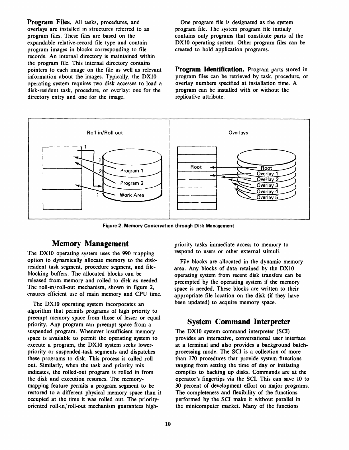
Figure 2. Memory Conservation through Disk Management
~eliDory
The
DXIO
operating system
option to dynamically allocate memory to the diskresident task segment, procedure segment, and fileblocking buffers. The allocated blocks can
released from memory and rolled to disk as needed.
The roll-in/ roll-out mechanism, shown in figure
ensures efficient
The
DX I 0 operating system incorporates an
algorithm that permits programs of high priority to
preempt memory space from those
priority. Any program can preempt space from a
suspended program. Whenever insufficient memory
space
is
available to permit the operating system to
execute a program, the
or
priority
these programs to disk. This process
out. Similarly, when the task and priority mix
indicates, the rolled-out program
the disk and execution resumes. The memorymapping feature permits a program segment to
restored to a different physical memory space than it
occupied
oriented roll-in/ roll-out mechanism guarantees high-
suspended-task segments and dispatches
at
the time it
~anageliDent
uses
the
990
mapping
be
use
of main memory and CPU time.
of
lesser or equal
DXIO
system seeks lower-
is
called roll
is
rolled
in
was
rolled out. The priority-
2,
from
be
Overlays
Root
-
=3
priority tasks immediate access to memory to
respond to users or other external stimuli.
File blocks are allocated in the dynamic memory
area. Any blocks of data retained by the
operating system from recent disk transfers can
preempted
space
appropriate
been updated) to acquire memory space.
The
provides an interactive, conversational user interface
at a terminal and also provides a background batchprocessing mode. The SCI
than
ranging from setting the time
compiles to backing up disks. Commands are
operator's fingertips via the SCI. This can save
30
percent
The completeness and flexibility of the functions
performed by the SCI make it without parallel in
the minicomputer market. Many of the functions
by
the operating system if the memory
is
needed. These blocks are written to their
file
location on the disk (if they have
SysteliD
DXIO
170
COliDliDand
system command interpreter (SCI)
procedures that provide system functions
of
development effort on major programs.
£:..
~
'-
..
~OVerlay
~
~Overlav3
Overlav2
Interpreter
is
a collection
of
Root
1
DXIO
be
of
more
day or initiating
at
the
10
to
10
Page 18
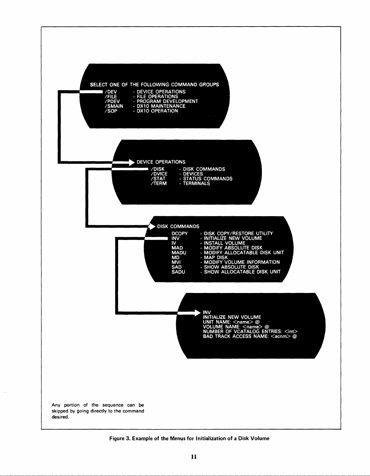
Any
portion of the sequence can
skipped by going directly to the command
desired.
be
Figure 3. Example of the Menus for Initialization
11
of
a Disk Volume
Page 19

performed by the SCI are found only on main-frame
machines. Table I lists the general categories
functions provided by the
DXIO
operating system
of
and initiated by the SCI.
Appendix A lists all standard SCI commands
DXIO
available with the
of SCI commands
operating system. Activation
is
via a hierarchy
of
command
menus made available to all types of system
terminals. The command menus provide each
terminal on-line command prompts
by
logical
grouping. The example in figure 3 illustrates the
menus for initialization of a disk volume.
Custom commands can
of
framework
the DXIO operating system. Users can
be
integrated into the
combine SCI primitives with their own application
is
language to provide a user interface that
to the terminology and customary procedures
is
application. Figure 4
an example of a custom
unique
of
the
procedure.
Table 1. Areas Served by DX10
Log
in
and
out
Time and
Disk volume initialization, installation,
and unloading
Disk
Directory and file creation and deletion
Synonym
File alias name
File name changing and protecting
Directory and
Directory and
Logical unit assignment, positioning, and release
System I/O
·Systemtaskstatusdisplay
Program activation and control
Batch
Station
Program
System log
Program debugging including:
Text
COBOL, RPG II, DBMS
BASIC,
assembly-language assemblies
Link Edit activation
Sort/Merge activation
date
setup
and ill4uiry
directory
command
Breakpoints
Memory/disk
Decimal/hexadecimal
I nteractively controlled program trace
Edit
backup, restore,
support
file viewing and listing
file copying
status
display
input,
activation, and
control
(user I D, terminal status, etc.)
installation and deletion
activation
dump
or
display
arithmetic
control
990,
FORTRAN,
and Pascal compilers and
SCI
Commands
and
copy
status
aid
Business BASIC,
SELECT ONE OF THE FOLLOWING
COMMAND GROUPS
/PROG
/ENTRY
\ /APPL
.l
APPLICATIONS
/ACCT
/PAY
/INV
/ANAL
~
PAYROLL
I
/WKPAY /MTD
/YTD
/W2
/W4
\
J
WJ:J:1l1 v PAVDnl
7 -------
NAME
DEPT.
REG. HRS.
DEDUCTIONS INS.
MED.
Figure 4. Custom Procedure Example
Interactive Operation. The
PROGRAM OPERATIONS
DATA
-
.......
ENTRY
APPLICATIONS
ACCOUNTING
-
PAYROLL
INVENTORY
-
SALES
-
-
-
-
-
ANALYSIS
WEEKLY
MONTH
YEAR
W2
W4 PROCESSING
_--
PAYROLL
TO
TO
DATE
PROCESSING
I
EMP.NO.
RATE
O.T.HRS.
CONT'
DXIO
operating
DATE
___
__
';
__
j
system features an excellent interactive user interface
for control
keyed
·Fieldsare-easily edited
verified by the system. The number
therefore time, can
for a command can
of
the system through SCI.
by
an operator are meaningfully prompted.
by
tne'opetaI6tario'are
be
conserved since all arguments
be
entered before the system
All
of
prompts, and
entries
.,
requests them by prompt. When a partial list of
arguments
is
entered, any arguments not already
supplied by the operator or default specified are then
prompted.
Batch Operation. The background program at the
be
terminal may
is
SCI
interpreting commands in the background
(batch processing). Batch input
sequentially oriented
terminal itself. An operator can initiate batch
processing, query its status, and receive information
concerning its normal or abnormal completion.
Certain interactive commands are inappropriate for
batch operation, but all other SCI commands are
available.
a copy of the SCI. In this case, the
is
from any
file
device but not from the
12
Page 20
File
The
management package that includes a complete range
of file structures and features. The DXI0 system can
accommodate many uniquely named data files on a
disk pack and can allocate disk space to the files.
The amount of space allocated to a
small as two disk sectors or as large as all of the
available space on the disk cartridge. The user can
specify the amount of space to be allocated to a
Of;
automatically allocated
Management
DXI0
operating system
more frequently, can specify that space
to
is
based on a file-
the
file
as it
file
can be as
is
is
to be
needed.
file
File Types
Three major
operating system: sequential, relative-record, and
multikey-indexed
file
types are supported by the
files.
DXI0
For example, an employee' file can be constructed
so the data record for any given employee can be
by
accessed
number, social security number, or any other
designated key.
Key
are kept in indexes within the files. These indexes
are hierarchically structured. This allows both rapid
random access
sequential access to all records in the file in the
stored order
The user can perform the following types
functions with key-indexed
• Randomly read any record.
• Insert and delete records. (Records are
automatically blank suppressed on insertion, and
duplicate key values are allowed.)
supplying the employee's name, employee
values for both primary and secondary keys
to
any record within the file
of
any selected
key.
files:
or
of
Sequential Files. Sequential files are useful for
recording data records in the order received.
Similarly, data
pointer to the current file position
DXI0
operating system for each active assignment to
the file.
pointer
can exist beyond the most recently written record.
The only exception to this rule
rewrite
can be segmented, and support for mUltiple end-offiles within a sequential file
programs can concurrently read a sequential disk
at
cannot be shared if
As
is
of
different positions in the file. A sequential file
is
returned in the same order. A
is
kept
by
the
each record
advanced. In sequential files, no valid data
a record
is
read
or
written, the
is
that a limited
is
supported. A sequential file
is
provided. Several
it
is
being modified.
file
Relative-Record Files. Relative-record files are
optimized for rapid random access. Fixed-length
records are accessed by supplying the DXI0
operating system the record number within the
Such
files
are useful when the data lends itself to
of
computation
increments the caller's record number after each read
or
write; so a sequential access
end-of-file record
a record number. The DXIO system
is
permitted. One
is
maintained.
file.
Multikey-Indexed Files. In multi key-indexed
files, variable-length records are accessed by
providing the DXI0 operating system
to fourteen keys by which the data
is
a string of up to
position within the record.)
possible keys must be selected as the primary key.
All other keys are known as secondary keys.
Primary keys must be present in all records, but
secondary keys can be optionally absent in any given
record within the file.
100
characters
One of the fourteen
anyone
is
known. (A key
at
a fixed
of up
• Establish a generic file position as in a COBOL
start command.
• Read files sequentially in the sort order
key starting at an established
can be read in ascending
• Add, delete, or change a secondary-key value
when records are updated.
Multikey indexing provides a unique selfmaintenance capability. Deleted
automatically removed
lists. The DXI0 operating system automatically
or
expands
much of the necessity for periodically rebuilding and
reorganizing files.
contracts the key lists and eliminates
or
file
or
descending order.)
or
added keys are
inserted in the sorted key
of
a given
position. (Files
File Features
Various
the assembly-language user. High-level languages may
or
depending on the syntax
language programs can be written and called from
high-level-language programs to allow indirect access
to a feature.
Record Locking. The DXI0 operating system
supports locking individual records within a file.
This feature allows a program exclusive access to the
locked record until that record
example might be locking an inventory record while
updating the quantity in stock. The lockout prevents
programs responding to other terminals from
updating the same quantity before the first update
complete.
file
features and
may not allow access to any given feature,
file
types are available to
of
the language. Assembly-
is
unlocked. An
is
13
Page 21
Temporary Files. The OXIO operating system
allows the use
subject
to
This feature allows a trial preparation
the prepared file is satisfactory, it
and designated as permanent.
Blocked Files. Multiple logical records
automatically combined by the
system into larger physical records. These larger
records are called file blocks
Blocking conserves disk space
number
memory
of
temporary files. These files are
subsequent deletion by the OX I 0 system.
of
a file.
can
be renamed
can
OXIO operating
or
physical records.
and
reduces the
of
physical transfers
and
disk.
of
data
between
If
be
Deferred or Immediate Write. The physical
transfer
deferred by the
memory space held by the blocking buffer
required for some other purpose. This reduces the
number
recalled. The
disk before the file
be desirable (e.g., for security) for all writes
to occur immediately upon request. The
system supports this immediate write option.
of
logical-record blocks
to
OX I 0 operating system until the
of
physical disk accesses since
OXIO system updates the image
is
closed. In some cases, it
disk
is
normally
data
OXIO
is
may be
of
may
to
a file
the
be optionally removed from each record. Blank
of
compression encodes strings
consecutive blanks
within the record in a shortened form. Blank
adjustment removes trailing blanks
and
operation
replaces them on a subsequent read
operation. Blank adjustment
is
available
on
a write
to
devices
as well as files.
Expandable Files. The OXIO operating system
permits declaration
Unless otherwise specified, additional space
allocated when the file exceeds this initial allocation.
In this way, files continue
initial bounds. These secondary allocations
become increasingly larger as the file expands
beyond its current extent.
Other System
Overhead
VCATALOG
of
the file size
---~r--
--,.0:---.-..;
at
file creation.
to
grow beyond their
is
to
the file
Delete and Write Protection. After each file
created, it
from the volume.
to
further protect a file. The OXIO operating system
permits file write protection, which only allows the
data
automatically delete-protected.
Access Privileges.
program
is defined
through
can
be protected from accidental deletion
In
some cases, it may be desirable
to
be read. Files
can
request specific access privileges. A use
as
the entire file transaction from open
that
are write-protected are
For
any use
close; These privileges include:
Privilege Function
Exclusive Access Only the
access
Exclusive
Write Access
Shared Access
Only
Read
Only
write
The
file for read and write operations.
The
ited from writing
calling program can
the
file.
the
calling program can
to
the
file.
calling program shares
calling program
of
a file, a OXIO
is
prohib-
to
the
file.
the
is
User Files
and Directories
Volume
Disk Cartridge
System Files
or
Disk Pack
-----'
Name-----~
Blank Compression and Adjustment.
that
types
support variable-length records (Le., all
For
file
files except relative-record files), blank characters can
14
Figure 5.
Disk-Volume Layout
Page 22
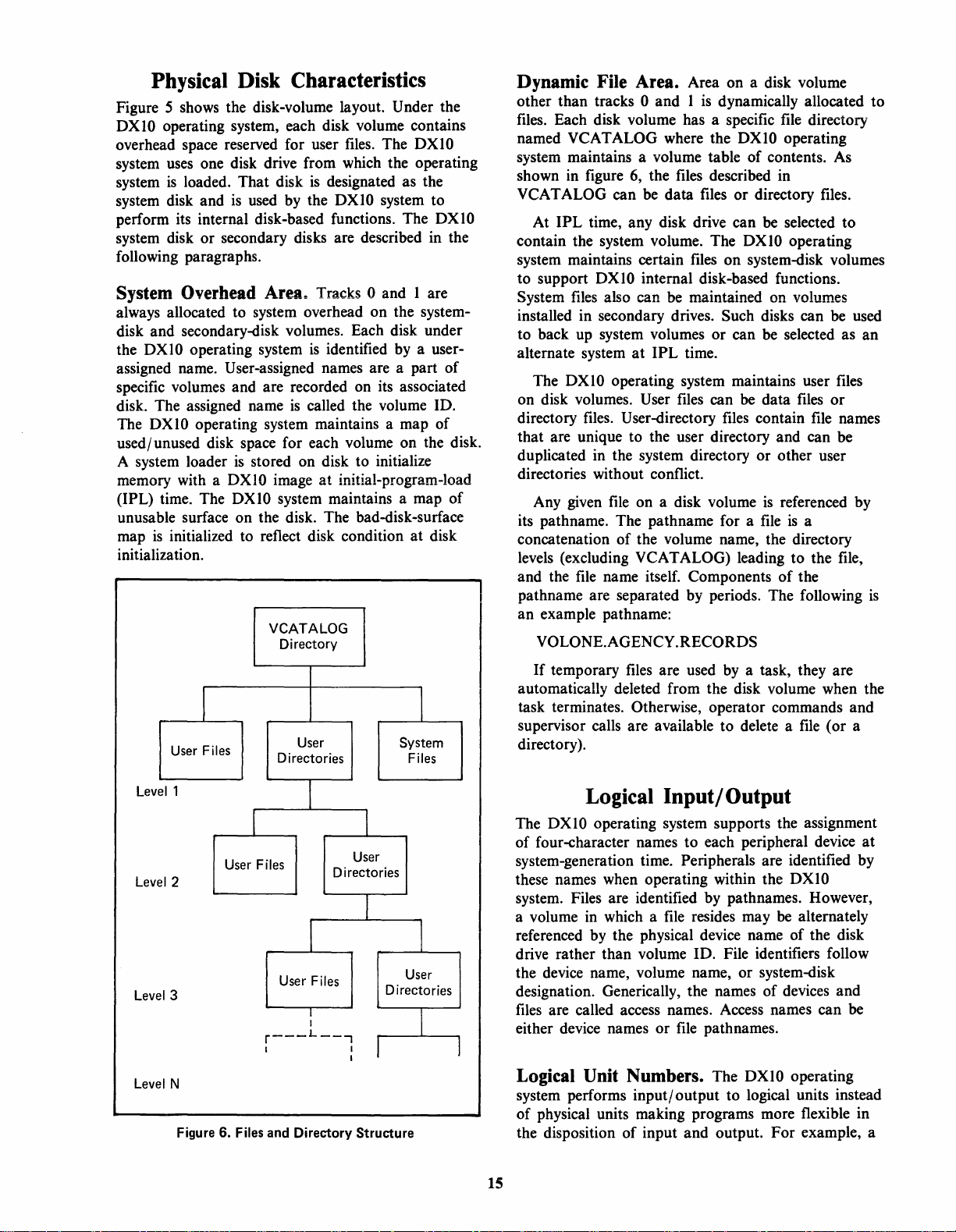
Physical Disk Characteristics
Figure 5 shows the disk-volume layout. Under the
DXIO operating system, each disk volume contains
overhead space reserved for user
system
system
system disk and
perform its internal disk-based functions. The DXlO
system disk or secondary disks are described in the
following paragraphs.
System Overhead
always allocated to system overhead on the system-
disk and secondary-disk volumes. Each disk under
the
assigned name. User-assigned names are a part of
specific volumes and are recorded on
disk. The assigned name
The
used/unused disk space for each volume on the disk.
A system loader
memory with a
(IPL) time. The
unusable surface on the disk. The bad-disk-surface
map
initialization.
uses
one disk drive from which the operating
is
loaded. That disk
is
used by the DXlO system to
Area~
DXIO
operating system
is
DXIO operating system maintains a map of
is
stored on disk to initialize
DXIO
image
DXIO
system maintains a map of
is
initialized to reflect disk condition at disk
VCATALOG
Directory
files.
The
DXIO
is
designated as the
Tracks 0 and 1 are
is
identified
called the volume ID.
at
initial-program-load
by
its
associated
a user-
Dynamic File Area. Area on a disk volume
other than tracks
files.
Each disk volume has a specific
named
system maintains a volume table of contents.
shown in figure
VCAT
contain the system volume. The
system maintains certain
to support
System
installed in secondary drives. Such disks can
to back up system volumes
alternate system
on disk volumes. User
directory files. User-directory
that are unique to the user directory and can be
duplicated in the system directory or other user
directories without conflict.
its pathname. The path name for a
concatenation of the volume name, the directory
levels (excluding
and the
pathname are separated by periods. The following
an example pathname:
VCATALOG where the DXIO operating
ALOG can
At IPL time, any disk drive can
files
The
DXIO
Any given
file
VOLONE.AGENCY.RECORDS
0 and 1
6,
the files described in
be
DXIO
internal disk-based functions.
also can be maintained on volumes
at
IPL time.
operating system maintains user
file
on a disk volume
VCATALOG) leading to the file,
name itself. Components
is
dynamically allocated to
file
directory
data files or directory files.
be selected to
DXIO operating
files
on system-disk volumes
or
can be selected as an
files
can
be
data
files
files
contain
is
file
file
referenced by
is
a
of
the
As
be
files
or
names
used
is
Lev
Lev
el3
Lev
Level
el
el
I
User
Files
1
User
2
N
Figure 6. Files
Directories
Files
User
r---
I
and
User
Directories
Files
I
I
L
--..,
Directory
User
I
Directories
I
r
Structure
I
System
Files
I
User
I
1
If
temporary
automatically deleted from the disk volume when the
task terminates. Otherwise, operator commands and
supervisor calls are available to delete a
directory).
files
are used
by
a task, they are
file
(or a
Logical Input/Output
The
DXIO
operating system supports the assignment
of four-character names to each peripheral device
system-generation time. Peripherals are identified by
these names when operating within the
system. Files are identified by pathnames. However,
file
a volume in which a
referenced by the physical device name of the disk
drive rather than volume ID. File identifiers follow
the device name, volume name, or system-disk
designation. Generically, the names of devices and
files
are called access names. Access names can be
either device names or
resides may
file
pathnames.
DXIO
be
alternately
Logical Unit Numbers. The DXIO operating
system performs input/ output to logical units instead
of physical units making programs more flexible in
the disposition of input and output. For example, a
at
15
Page 23
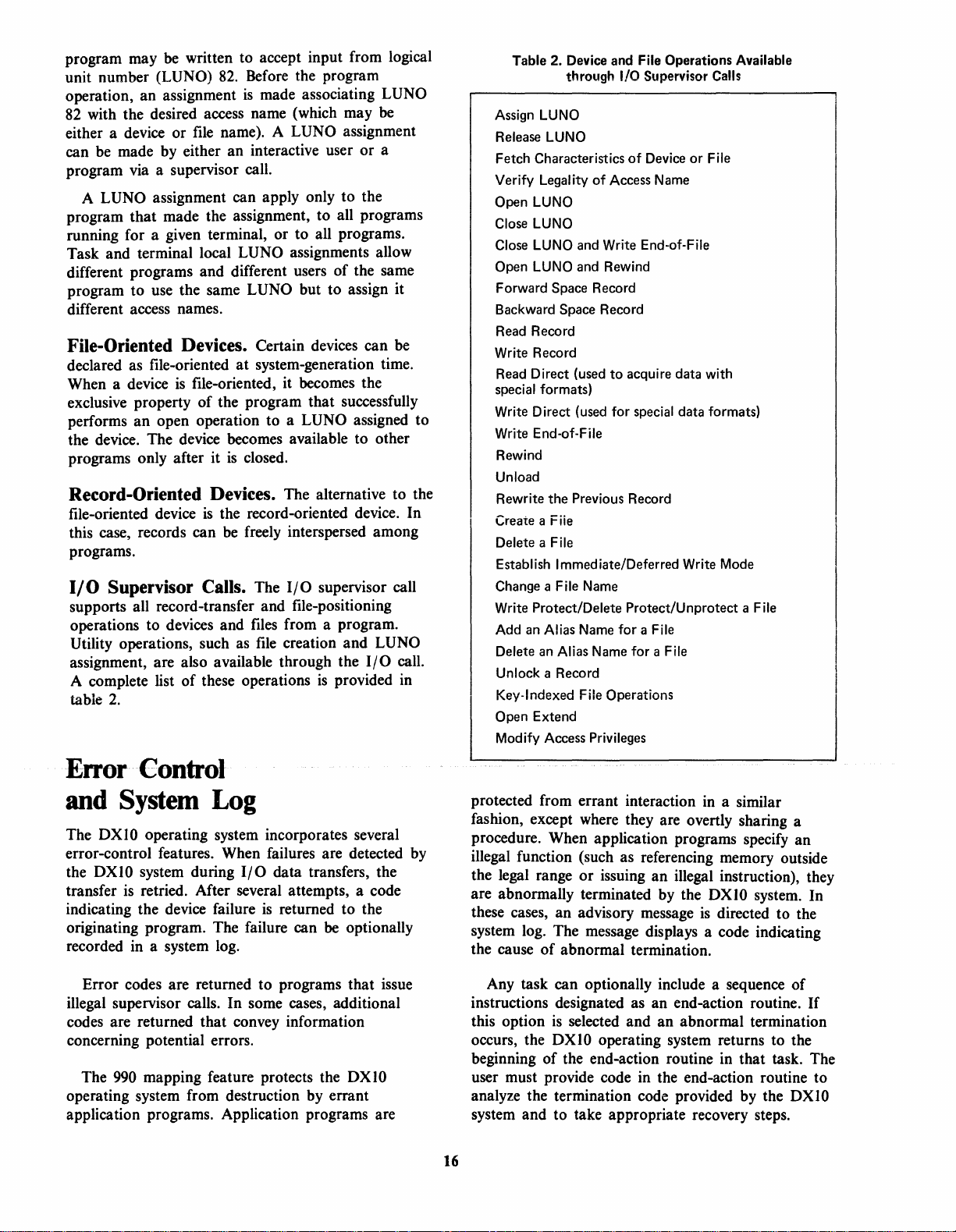
program may
unit number
operation, an assignment
82
with the desired access name (which may
either a device or
be
written to accept input from logical
(LUNO)
82.
Before the program
is
made associating LUNO
file
name). A LUNO assignment
be
can be made by either an interactive user or a
program via a supervisor call.
A
LUNO assignment can apply only to the
program that made the assignment, to all programs
running for a given terminal, or to all programs.
Task and terminal local
LUNO assignments allow
different programs and different users of the same
program to use the same
LUNO but to assign it
different access names.
File-Oriented Devices. Certain devices can
declared as file-oriented
When a device
is
exclusive property
performs an open operation to a
at
system-generation time.
file-oriented, it becomes the
of
the program that successfully
LUNO assigned to
be
the device. The device becomes available to other
programs only after it
is
closed.
Record-Oriented Devices. The alternative to the
file-oriented device
this case, records can
programs.
110 Supervisor Calls. The
supports all record-transfer and file-positioning
operations to devices and files from a program.
Utility operations, such as
assignment, are also available through the
A complete list of these operations
table
2.
is
the record-oriented device. In
be
freely interspersed among
I/O
supervisor call
file
creation and LUNO
I/O
is
provided in
call.
Table 2. Device and File Operations Available
through
Assign
LUNO
Release
Fetch Characteristics
Verify
Open
Close
Close
Open
Forward Space Record
Backward
Read Record
Write Record
Read Direct (used to acquire data with
special formats)
Write Direct (used for special data formats)
Write End-of-File
Rewind
Unload
Rewrite the Previous Record
Create a Fiie
Delete a File
Establish Immediate/Deferred Write
Change a File Name
Write
Add
Delete
Unlock a Record
Key-Indexed File Operations
Open Extend
Modify Access Privileges
LUNO
Legality of Access Name
LUNO
LUNO
LUNO
LUNO
Space Record
Protect/Delete Protect/Unprotect a File
an
Alias
an
Alias Name for a File
I/O Supervisor Calls
of
Device
or File
and Write End-of-File
and Rewind
Name
for a File
Mode
Error Control
and System Log
The
DXIO
error-control features. When failures are detected by
the
DXIO
transfer
indicating the device failure
originating program. The failure can
recorded in a system log.
Error codes are returned to programs that issue
illegal supervisor calls. In some cases, additional
codes are returned that convey information
concerning potential errors.
The
operating system from destruction by errant
application programs. Application programs are
operating system incorporates several
system during
is
retried. After several attempts, a code
990
mapping feature protects the
I/O
data transfers, the
is
returned to the
be optionally
DXIO
protected from errant interaction
in
a similar
fashion, except where they are overtly sharing a
procedure. When application programs specify an
illegal function (such as referencing memory outside
the legal range
are abnormally terminated by the
these cases, an advisory message
or
issuing an illegal instruction), they
DXIO
system. In
is
directed to the
system log. The message displays a code indicating
the cause
of
abnormal termination.
Any task can optionally include a sequence of
instructions designated as an end-action routine.
this option
occurs, the
is
selected and an abnormal termination
DXIO
operating system returns to the
beginning of the end-action routine in that task. The
user must provide code in the end-action routine to
analyze the termination code provided by the
system and to take appropriate recovery steps.
16
If
DXIO
Page 24
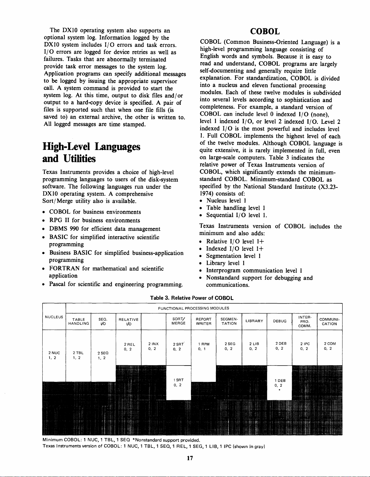
The DXI0 operating system also supports an
optional system log. Information logged by the
DXIO
system includes
I/O
errors are logged for device retries as
I/O
errors and task errors.
well
as
failures. Tasks that are abnormally terminated
provide task error messages to the system log.
Application programs can specify additional messages
to
be logged by issuing the appropriate supervisor
call. A system command
system
log.
At this time, output to disk
output to a hard-copy device
files
is
supported such that when one
saved to) an external archive, the other
is
provided to start the
files
is
specified. A
file
fills (IS
is
and / or
pa~r
of
written to.
All logged messages are time stamped.
High-Level
and
Utilities
Languages
Texas Instruments provides a choice of high-level
programming languages to users of the disk-system
software. The following languages run under the
DXI0 operating system. A comprehensive
Sort/ Merge utility also
is
available.
• COBOL for business environments
• RPG II for business environments
• DBMS
990
for efficient data management
• BASIC for simplified interactive scientific
programming
• Business BASIC for simplified business-application
programming
• FORTRAN for mathematical and scientific
application
• Pascal for scientific and engineering programming.
COBOL
COBOL (Common Business-Oriented Language)
high-level programming language consisting of
English words and symbols. Because it
read and understand,
COBOL programs are largely
is
easy to
self-documenting and generally require little
explanation.
For
standardization, COBOL
into a nucleus and eleven functional processing
modules. Each
of
these twelve modules
is
into several levels according to sophistication and
completeness. For example, a standard version of
COBOL can include level 0 indexed
l~~el
1 indexed
indexed
1.
I/O
Full COBOL implements the highest level
I/O,
or level 2 indexed
is
the most powerful and includes level
of the twelve modules. Although
quite extensive, it
is
rarely implemented in full, even
I/O
(none),
1/
O.
COBOL language
on large-scale computers. Table 3 indicates the
relative power of Texas Instruments version of
COBOL, which significantly extends the minimumstandard
COBOL. Minimum-standard COBOL as
specified by the National Standard Institute (X3.23-
1974)
consists
of:
• Nucleus level 1
• Table handling level 1
• Sequential
I/O
level
1.
Texas Instruments version of COBOL includes the
minimum and also adds:
• Relative
• Indexed
I/O
I/O
level
1+
level 1 +
• Segmentation level 1
• Library level 1
• Interprogram communication level 1
• Nonstandard support for debugging and
communications.
is
a
is
divided
subdivided
Level 2
of
each
is
NUCLEUS
2 NUC
1, 2
Minimum
Texas
Instruments
version
SEQ.
2 SEQ
1,
of
TABLE
HANDLING
2
TBL
1,
2
COBOL: 1 NUC, 1
Table 3. Relative Power
RELATIVE
I/o
2
TBl, 1 SEQ * Nonstandard
COBOL: 1 NUC, 1
I/o
2
REL
0,
2
21NX
0, 2
TBl, 1 SEQ, 1 REl, 1 SEG,
FUNCTIONAL
SORT I
MERGE
2
SRT'
0, 2
support
PROCESSING
REPORT
WRITER
provided.
17
of
MODULES
1
RPW
0,
1
1 LIB, 1 IPC
COBOL
SEGMEN-
TATION
2 SEG
0, 2
(shown
LIBRARY
2
LIB
0, 2
.
In
gray)
DEBUG
2 DEB
0,
2
INTER-
PRO.
COMM.
2 IPC
0,
2
COMMUNI-
CATION
2COM
0,
2
Page 25
The COBOL compiler/interpreter runs under the
DX 1
0 disk operating system on a
is
compiler
software. The
compiler / interpreter; a COBOL program
to produce an intermediate language and
execution time
intermediate language. This feature provides a
powerful debugging tool;
single-statement mode, allowing the user to easily
detect an erroneous statement.
Features
minicomputer programming language with the
following features.
Data Types. COBOL can process decimal numbers
with up to eighteen digits (with
Numbers can
alignment. The
statement allows
Character strings
the
COBOL data structures allow a series of
contiguous data fields to be treated as a single
character string. The data structures support arrays
of
up to three dimensions.
Arithmetic Operations. The basic arithmetic
operators of
MULTIPLY, and DIVIDE. Rounding
be specified on any arithmetic operation, and the
user can specify the action to
ERROR
Character-String Handling. Full COBOL numeric
and alphanumeric editing capabilities
flexibility in formatting numbers for output.
Character strings can
the comparison
that the shorter string
INSPECT statement provides the capability for
counting
character in a character string.
Program Control. The
execution based on the logical truth or falsity of a
condition. The condition may be an expression,
named condition,
conditions linked by AND and OR.
can have
The
specified location in the program or to one
several possible locations, depending on the value of
a variable.
The
program to
subroutine. The code segment specified in the
PERFORM statement can
controlled by the
COBOL translator
an
interpreter executes the
COBOL can
of
COBOL. COBOL
be
scaled with automatic decimal-point
USAGE IS COMPUTATIONAL-I
use
of
16-bit binary numbers.
of
fixed length are allowed, and
COBOL are ADD, SUBTRACT,
(field overflow) should occur.
be
right- or left-justified, and
of
unequal-length strings assumes
is
extended by·blariks. The
and/or
ELSE clauses and can
GOTO statement transfers control to a
PERFORM statement allows a portion of the
replacing occurrences of a specified
IF
or
logical combination
be
executed as a parameterless
be
990
computer. The
DXIO
disk-system
is
a
is
compiled
at
be
executed in
is
a powerful
or
without a sign).
of
results can
be
taken if a SIZE
give
great
statement controls
of
IF
statements
be
nested.
of
executed once, some
number
repetitively until a condition
V AR YING option can
variable for each repetition.
routines that have been separately compiled and
linked together; this simplifies program development.
and devices in addition to random-access
accessed by record numbers
On random-access files, COBOL can READ records,
WRITE new records, REWRITE (replace) records,
and DELETE records. Random and sequential
accesses can be mixed on random-access files. For
example, the user might
read a specific record (in a key-indexed
then sequentially read the following records.
rewinding. A sequential
end
extend the
other users of a shared
while it
COBOL. The user can specify the FILE STATUS
variable to receive error codes from
and can specify code to
I/O
incorporate source text from a library
program. Commas and semicolons can be used to
separate clauses and statements. Data names and
paragraph names may be qualified
or section they are in. Programs can be separated
into
read-only memory
memory (RAM). Current time and date (maintained
by
COBOL.
I/O
includes significant extension to the ACCEPT and
DISPLA Y statements to facilitate interactive
with a video display terminal. The ACCEPT and
DISPLAY statements can specify the position of the
field
number, column number, and
than one screen field can
statement. In addition, the
an option to clear the entire screen before output.
The ACCEPT statement has options for converting
numeric inputs, initializing the screen field with
asterisks, and echoing the received data in fieldjustified form.
of
times determined
The CALL statement allows the program to call
Input/ Output. COBOL supports sequential
Sequential
of
READ WITH LOCK can
Two
errors.
Other Features. The
code and data portions f()t partitioning into
the operating system) can
files
can
the
file
so subsequent WRITE operatioris
file.
is
being updated.
files
can share the same buffer area under
(ROM) and random-access
by
a variable, or
is
satisfied. The
be
used to increment a
or
character-string
use a key
be
opened with
file
can
file
from accessing the
be
executed in the event
COpy
to locate and
be
opened
be
used to prevent
clause can be used to
by
be
accessed via
files
files
file)
and
or
without
at
I/O
operations
file
into the
the structure
keys.
the
file
with Video Display Terminal. COBOL
I/O
on the screen to be referenced as a line
field
length. More
be
referenced in a single
DISPLAY statement has
will
of
18
Page 26
Debugging Facilities. A COBOL program can
include debug lines, which are indicated by a D in
column
of the program or treated as comments, depending
on a compiler option.
cross-reference listing that lists all of the identifiers
(data-item names, index names, condition names,
names, section names, and paragraph names) used in
the program, along with the line number
appearance. Where a variable appears, the line
numbers are flagged as a declaration, reference,
modification
the
execution, the debug monitor allows the user to
execute the program
execute a single statement. The contents of data
locations can be displayed between executions
portions
Elements
discuss Texas Instruments version of
discussion
modules in
nucleus with limited capabilities for
ALTER, DIVIDE,
MOVE, MULTIPLY, PERFORM,
and with full capabilities for EXIT, GO, and STOP.
COBOL
level
• Full capabilities for ALTER and
• Full capabilities for PERFORM
• Separators
•
• Full
• Figurative constants including ZERO, ZEROS,
•
• Full level 2 condition-name conditions
• Data levels
• THRU and THROUGH as equivalent
• Level 2 relational characters
• Comparisons of nonnumeric literals of unequal
• AND, OR, and NOT connectives.
7.
These lines
The
COBOL compiler has an option of printing a
of
COBOL programs are executed under control of
COBOL debug monitor. Besides normal
of
a program.
of
COBOL. The following paragraphs
is
divided into parts corresponding to the
COBOL.
Nucleus. COBOL implements all of the level 1
also implements the following features from
2:
comma and semicolon
Level
2 data names (Names need not begin with
an alphabetic character.)
level
2 qualifications (Names need not
unique if they can
qualification.)
ZEROES, SPACE, SPACES,
HIGH-VALUES, LOW-VALUE, LOW-VALUES,
QUOTE,
Full
literal can
appears on a continuation line.)
length
and QUOTES
level
2 continuation capabilities (A word or
be
11-49
will
either
be
compiled as part
the variable.
up
to a specified point or to
ACCEPT, ADD,
DISPLAY, IF, INSPECT,
and SUBTRACT
IF
be
made unique through
HIGH-VALUE,
broken
in
such a way that part of it
>, <,
of
each
or
of
COBOL. This
be
and =
file
In addition, COBOL has powerful extensions to
ACCEPT and DISPLAY statements to allow the
the
user exact control of the video display terminal.
Table Handling. COBOL provides the capability to
use tables of up to three dimensions and to vary the
access index by an increment or decrement. The
OCCURS, USAGE, and SET clauses are supported.
Sequential 1/
capabilities for
statements and full capabilities for the READ,
REWIND, and REWRITE statements.
extends
WITH
include EXTEND or
capabilities for relative
capabilities for the
CONTROL,
capabilities for
REWIND, REWRITE,
DYNAMIC, READ NEXT, and
level 2 features not present are the
SAME RECORD AREA clauses.
capabilities for FILE-CONTROL, I-O-CONTROL,
and
DELETE, READ, REWRITE, START, USE,
WRITE, DYNAMIC, READ NEXT, and START.
The dynamic access feature of
alternate and duplicate
segmentation capabilities to allow efficient generation
of overlay capabilities. Actually, since
compiler/interpreter, the size of a program does not
provide as significant a limitation as it would with a
compiler language. The
language interpreter need only keep the relevant data
base and the single instruction being executed
memory
program can reside on disk.
functions including the
statement extends the standard in that the text
produced by a
COpy
allowed.
global, the syntactic correctness of a
program cannot
statements (including those in COPYed text) have
been fully expanded.
level I CALL statement and
passing parameters. CALL and EXIT
level
LOCK and also extends level 1 OPEN to
Relative I/O. COBOL provides level
Indexed I/O. COBOL provides level
FD
Segmentation. COBOL provides level I
Library. COBOL implements level I library
statement. Up to
Interprogram Communication. COBOL implements
O.
COBOL provides limited
OPEN, CLOSE, USE, and WRITE
COBOL
1 CLOSE to include multiple
NO REWIND.
I/O.
Included are level 1
FILE-CONTROL, 1-0-
and
FD
entries and full
CLOSE, DELETE, READ,
START, USE, WRITE,
START. The only
RESERVE and
entries and full capabilities for CLOSE,
level 2 is
keys
are not supported.
COBOL intermediate-
at
a given instant. The remainder of the
COpy
COpy
Since some elements of COBOL syntax are
statement can include another
be
determined until all
statement. The
five
levels of nesting are
USING clause for
files
and
1+
level
2
1+
supported;
COBOL
COBOL source
COpy
PROGRAM
is
a
in
COpy
19
Page 27
allow control
programs in a run unit.
to
pass back and forth between
Debugging. The COBOL compiler/interpreter
supplies powerful nonstandard debugging tools. In
addition
D in column 7), the interpreter supplies two options.
The user can specify
block
Or, the user can obtain a
(including type specification).
Comparison with
COBOL. Texas Instruments version
differs from standard (level
ways. All signed, numeric
1 have the attribute
SEPARA
in the size
COBOL convention.
feature and the
provided.
Some
features found on larger machines
provided
following paragraphs.
Data.
CORRESPONDING
DEPENDING
OCCURS
ALL
specified.
Arithmetic. No
on the DIVIDE statement. Only one destination
provided on arithmetic statements. There
COMPUTE
in
(POSITIVE; NEGATIVE,
SEARCH
Character Strings. There are no
UNSTRING
Input and Output. The
the report writer features are not provided. There
no label processing. Cards with over-punched signs
on
record
RPG
an
processing. Based upon a predetermined sequence
that
the results,
applications requiring file maintenance or report
generation. A series
to
optionally compiled lines (specified by a
COBOL execution for any
of
code including statement-at-a-time execution.
dump
Levelland
data
SIGN
TE. Thus, the S in the picture
of
the field, contrary to the usual
In
addition, the
CODE-SET
of
the more significant (level 2) COBOL
on
the 990 computer are discussed in the
Data
levels
do
not include level
cannot be used, and the
option cannot be used on
clause. There
literal. SIGN IS LEADING cannot be
statement. Expressions are not allowed
IF
statements. There are no sign condition tests
statement.
statements.
numeric fields cannot
on
an
indexed file can have the same key.
is
REMAINDER
or
Sort/
be
RPG
II (Report Program Generator, version II)
easy-to-use, high-level language for business
reads a record, processes the data, and outputs
RPG
II
is
especially suited for
of
six basic specification formats
of
any
Level 2
of
1)
COBOL in several
fields except
IS
TRAILING
RERUN
feature are not
that
are not
no
figurative constant
option
ZERO) and no
STRING
Merge feature and
read.
No
more than one
II
data
item
COBOL
COMP-
is
counted
66.
an
is
available
is
no
and
is
is
is
data
are used
within the
Texas Instruments version
is closely compatible with the widely used IBM
System/3
System/3 features have been included in
provide more flexible programming. A utility
program is provided with
or
to DS990 disk files.
oriented VDT text editor and a trace feature
prints each major step occurring during execution
an
sort/
Sort/
files
Emulator package.
to
input the specific actions to be taken
RPG
II seq uence
RPG
II. Extensions
System/32 source programs
The
RPG
II package also includes
RPG
II program. A System/3-compatible
merge capability is provided by the optional
Merge package, and communication
is
available through the optional DXIO 3780
of
of
RPG
execution.
the
RPG
II language
of
many
of
RPG
II
to
copy System/3
or
files from diskette
an
RPG
of
the
II to
11-
that
RPG
RPG II Hardware. Texas Instruments version
RPG
II
is
especially suited for users with rapidly
growing applications. The minimum system for
II
is
the Model 4 System. The Model 4 System
includes a 990 processor, I28K-byte
byte disk drive, 911 VDT terminal, single-bay desk
enclosure, and DXIO disk-system software license.
Expansion capabilities can provide large amounts
memory, multiple 50M-byte disk drives, and a
variety
Features
the following significant features:
• Efficient one-pass compiler
• Run-time trace
• Right-
• ASCII
• Capability to produce more
• Alphabetic summary listing
• Listing
of
additional standard 990 peripherals.
of
RPG II. The
that
program
or
left-hand sign handling
or
EBCDIC
diagnostic messages
arrays, and tables
of
all indicators specified in a program.
speeds the checking
internal
Comparison with System/3.
restrictive
areas. Table 4 lists these areas and the requirements
of
both the System/3 and
compatible with the System/3 where the hardware
and operating systems permit.
Several
on
Telecommunications Specifications sheet
supported by
is
not supported on the control card specifications.
than
the System/3 in a number
RPG
of
the System/3 features are not provided
Texas Instruments version
RPG
II. The P (Punch Card) function
memory~
RPG
II compiler has
character set
than
500 unique
of
all fields, labels,
RPG
II
II.
RPG
of
RPG
II. A
is
II
of
is
of
not
RPG
IOM-
the
less
is
of
II
of
of
20
Page 28
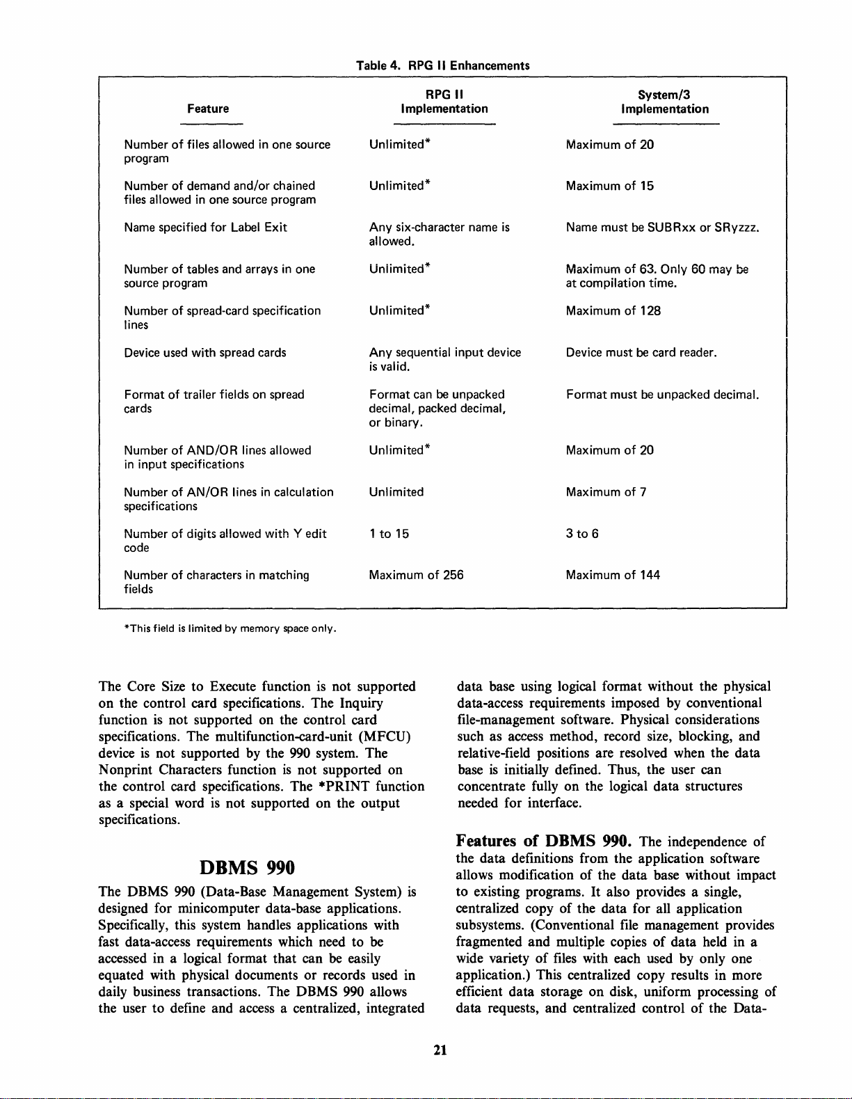
Feature
Table
4.
RPG
II
Enhancements
RPG
Implementation
II
System/3
Implementation
Number
program
Number
files allowed in one source program
Name
Number
source program
Number
lines
Device
Format
cards
Number
in input specifications
Number
specifications
Number
code
of
files allowed in
of
demand and/or chained
specified
used
of
for
Label
of
tables
and
arrays in
of
spread-card specification
with
spread
trailer fields on
of
AND/OR
of
AN/OR
of
digits allowed
lines allowed
lines in calculation
one
Exit
cards
spread
with
source
one
Yedit
Unlimited*
Unlimited*
Any
six-character
allowed.
Uniimited*
Unlimited*
Any
sequential input device
is
valid.
Format
decimal, packed decimal,
or
Unlimited*
Unlimited
1
can
binary.
to
15 3
be
unpacked
name
is
Maximum
Maximum
Name must
Maximum
at compilation time.
Maximum
Device must
Format must
Maximum
Maximum
to
of
20
of
15
be
SUBRxx
of
63. Only 60 may
of
128
be
card reader.
be
unpacked decimal.
of
20
of
7
6
or
SRyzzz.
be
of
Number
fields
*This field
characters in matching
is
limited
by
memory
space
The Core Size to Execute function
only.
is
Maximum
not supported
on the control card specifications. The Inquiry
function
is
not supported on the control card
specifications. The multifunction-card-unit (MFCU)
device
is
not supported by the
N onprint Characters function
990
is
not supported on
the control card specifications. The
as a special word
is
not supported on the output
system. The
*PRINT function
specifications.
The DBMS
DBMS
990
(Data-Base Management System)
990
is
designed for minicomputer data-base applications.
Specifically, this system handles applications with
fast data-access requirements which need to
accessed in a logical format that can
be
be
easily
equated with physical documents or records used in
daily business transactions. The
DBMS 990 allows
the user to define and access a centralized, integrated
of
256 Maximum
of
144
data base using logical format without the physical
data-access requirements imposed by conventional
file-management software. Physical considerations
such as access method, record size, blocking, and
relative-field positions are resolved when the data
base
is
initially defined. Thus, the user can
concentrate fully on the logical data structures
needed for interface.
Features of DBMS
990.
The independence of
the data definitions from the application software
allows modification of the data base without impact
to existing programs.
It
also provides a single,
centralized copy of the data for all application
subsystems. (Conventional
fragmented and multiple copies
wide variety
of
files
file
management provides
of
data held in a
with each used by only one
application.) This centralized copy results in more
efficient data storage on disk, uniform processing of
data requests, and centralized control
of
the Data-
21
Page 29
Base Maintenance function. In addition, DBMS
990
provides optional password security for the most
elementary data level; this provides control and
protection of the data base from unauthorized access
or
tampering.
DBMS
interfaces to
990
User Interface. The primary user
DBMS 990 consist of the datadefinition language (DOL) and data-manipulation
language (DML).
DOL
provides the means to completely describe
DBMS 990 data base and its associated data
the
elements. The
source
output
is
is
DML
DBMS 990 data by supporting the reading
writing
DOL logical data-base-definition
compiled by the DOL compiler, and the
stored with its associated data on disk.
provides the user the means to manipulate
and/or
of
DBMS 990 data. DBMS
990
data can
be
accessed by imbedding the appropriate DML syntax
COBOL application program. COBOL
in a
to construct a call to
DBMS 990 that specifies the
function to be performed and the data element to
manipulated. DBMS
rPtnrn<!
.&_
thp
..
_&.&.a.
rP<!111t<!
...
...,
...
.a._
.a._u
..............
990
tn
processes the request and
th~
'"
............
{,",ADAI
""''''.&JI'''.L.J
""
..
",..
P.l.V6.1.Ql.ll.
..........
is
used
be
BASIC
BASI C
programming language used in a wide variety of
scientific and business problem-solving applications.
Texas Instruments version
interactive language that supports operation by
multiple users. Interaction with
operator-prompted user input
~n~Lsystetn
of program statements can
modified, debugged, and executed through the
BASIC commands.
system software. The language implemented by this
system
extensions to enhance its use in scientific and
business applications.
• Executive to process commands entered from a
• Reentrant, multiterminal interface modules to
• Reentrant run-time interpreter to perform
is
a powerful, easy-to-Iearn, high-level
of
BASIC
is
an
BASIC involves
of
program statements
~QlTIm~Jlds
..
BASICprograms consisting
be easily created, entered,
use
BASIC system operates under
The
is
similar to Dartmouth BASIC with certain
DXIO
disk-
The system includes the following components:
terminal
of
coordinate the interaction
the executive,
interpreter, and operating system
arithmetic and logical functions during the
execution of a
BASIC program.
of
BASIC and Business BASIC Systems. The
990
computer supports two BASIC systems:
scientific-oriented
Business
BASIC.
The BASIC system
BASIC as described in
Kemeny and Kurtz. Extensions to the Dartmouth
BASIC include:
• Integer arithmetic
• Expanded string manipulation
• CALL and subprograms
• Formatted output and input.
The Business
in that -
• A floating decimal replaces real arithmetic.
• Trigonometry and matrix arithmetic are not
supported.
• An extended
key-indexed
Components
consists of
thp
fl1n"'t;nn~l
..
...... _ ... _ ......
..,
..... " .............
• Executive
• Compiler
• POPS interpreter
• Run-time support
• Operating-system interface.
The executive and compiler are distinguished from
the rest by their storage management and their
language. They are written primarily in a macrotype
interpreter language called
address-formulated language. Each instruction
interpreted by a short machine-language program
that
b~anch~s
described by the POPS instruction. This action
provides for faster program execution.
Executive. The executive controls the operations
the system. It processes the commands that are
entered from the terminal. When required, it invokes
the compiler and the run-time-support components.
The executive performs all editing commands
directly.
Compiler. The compiler
executive, and diagnostics are listed on a line-by-line
basis.
POPS. The POPS interpreter
assembly language. It executes the
assembly subroutines required by the executive and
compiler.
Run- Time Support. The run-time support performs
arithmetic and logical functions that may
BASIC and business-oriented
is
similar to the Dartmouth
BASIC
Programming by
BASIC system differs from BASIC
I/O
package
is
provided including
files.
of
BASIC. The BASIC system
five
major components. Figure 7 shows
r~l~t'''ft'''J...""
""
.......
"J.v
,,~
..
.I.~.I..l.l.}'
+J..
VA
".""'.:)\",00
....
n ....
~~--~---
"'VII1PV11~11l"
POPS, which
to
~Joutille
t()~rf()rm
is
invoked by the
is
written in
lh(! .
POPS and
..
-
•
is
a single-
is
.Jl.lIlctiQn
be
required
of
22
Page 30
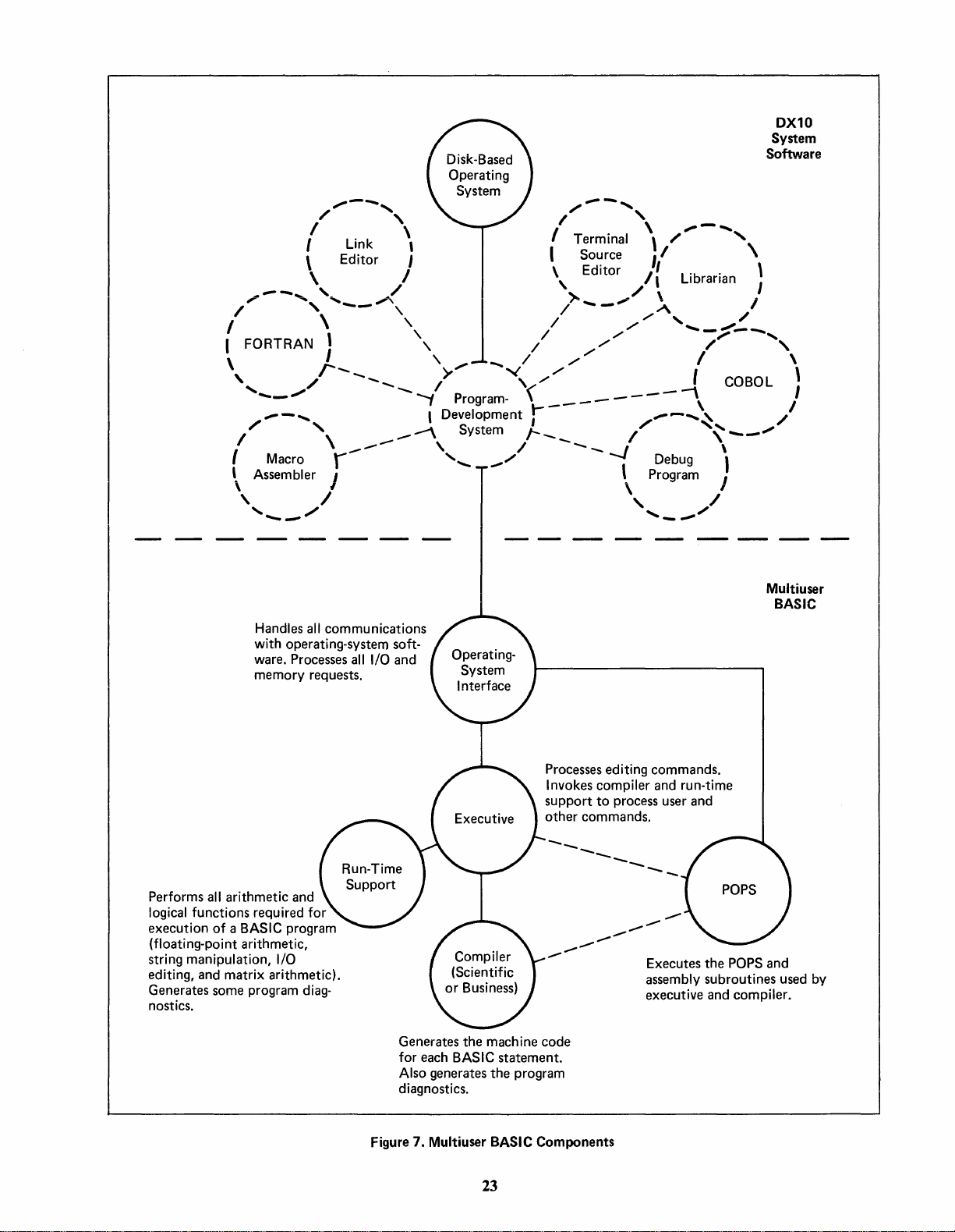
DX10
System
Software
~-~
/'
I
I Link , I Terminal \ " \
\ Editor
_--_.
/'
I /
I FORTRAN J " /
\
,
'
.....
/
I \
\
As~~~~er
, I , /
'
Handles
with operating-system software. Processes
memory requests.
\ I \ Editor " Librarian \
,_
~,
'--"',
\'
/'---_
_.......
~-,
'"
r "
......
_/
all
communications
' /
\ I
I Source I
_/
1 / -
,~-...
I>'
_-
all
__
I/O
........-..,
and
Program-
I
Development;
-"
System
, / - _
/./
""',
('
1--_
_/
~-,
/,
').
.....
/./"
_"
./././
././
_-------\
-J
\-
~".
_/
\ I
A i
./
.......
-,:\.
,/
"
P~~~r~~
......
_."",,/
"
....... _ ....... -......
/
/"',
I \
, COBOL \
"",--_
......
\
)
Multiuser
/
/
BASIC
Performs
logical
execution of a
(floating-point arithmetic,
string
editing, and matrix arithmetic).
Generates some program
nostics.
all
arithmetic and
functions required for
BASIC
program
manipulation,
I/O
diag-
Generates the machine code
for each
Also generates the program
diagnostics.
Figure 7.
BASIC
Multiuser
statement.
BASIC
23
Processes editing commands.
Invokes compiler and run-time
support
other commands.
--
-
Components
--
--
to
process user and
--
-
........
--
--
Executes the
assembly subroutines used
executive and compiler.
POPS
and
by
Page 31

Statement
-_
Purpose
Table 5.
...
-
.....
'
...
"'
...
"" ......
BASIC
and Business
BASIC
Statement
Statements
Purpose
CALL
CLOSE
DATA
DEF
DELETE
DIM
END
FIND
FOR
GOTO
GOSUB
IF
...
THEN
IMAGE
INPUT
Transfer
to
external subroutine
Close a file
Defines internal data block
Defines statement
Deletes a record from a
key-indexed file
Dimensions strings, vectors, and
matrices
Stops compilation
Sets record pointer
Defines top of loop and loop
parameters
Transfers unconditionally
Transfers
to
internal subroutine
Transfers conditionally
Picture and formatted print
Reads from terminal
ON
OPEN
PRINT
PRINTUSING
READ
READ
READUSING
REAL
REM
RESET
RESTORE
STOP
SUB
Computed GOTO or
GOSUB
Opens a file
Prints
to
output
device
Prints to
output
device under
control of image
Reads
from internal data block
READS record from file
Inputs values from a record on
file using
Specifies listed variables to
real
IMAGE
be
type
Comment line
Sets file
Reads internal
to
first record
READ
to start
of data block
Stops program
Defines start and parameters of
external subroutine
INTEGER
LET
NEXT
Statement
MAT
INPUT
MAT
READ
MAT
PRINT
MAT+
MATMAT
*
MAT
()*
Specifies listed variable
to
be
of
integer type
Evaluates expression and assigns
value,
all
types
Closes loop
Table 6.
Purpose
Matrix read from terminal
Matrix read from data block
Matrix print on terminal
Matrix addition
Matrix subroutine
Matrix multiplication
Scalar multiplication
SUBEND
WRITE
WRITEUSING
BAS
I C Matrix Statements
Statement
MAT
MATTRN
MAT
MAT
MATIDN
MAT
MAT=
(expression)
INV
CON
IDN
ZER
Returns from external
sub-
routine
Writes record
to
file
Writes record on file using
IMAGE
Purpose
Matrix inverse
Matrix transpose
Matrix
of
all
ones
Identify matrix
Identify matrix
Matrix of
Matrix of elements
all
zeros
all
set to
the expression value
24
Page 32

during execution of a BASIC program. These
functions include floating-point arithmetic, string
manipulation,
110 editing, and matrix arithmetic.
Referenced functions are read from a function
library stored on a sequential disk
file
and read
at
run time.
Operating-System Interface. The operating-systeminterface component handles all communications with
the DXlO operating system. All
110, memory
requests, data handling, and other such tasks are
performed by this component.
Table 8. Conditional Relations
Operator
EOor=
LTor<
LE
or
GTor>
GE
or>=
NE
or
<=
<>
or
or
or
= >
=>
><
Equal
Less
Less
Greater than
Greater than
Not
for
BASIC
Meaning
to
than
than or equal
or
equal
equal
BASIC System*
Business
BASIC BASIC
Numeric Functions
A A
A N
A N
A
A N
A A
A A
A A
A A
A A
A A
A N DET
A
A A
A A
A
A
A
A A
A A
A
A A
A
A A
A A
A
N
A
String Functions
A
A
A
A
A
A
Table 7.
Function
SOR
(X)
SIN (X)
COS
(X)
TAN
(X)
ATN (X)
LOG
(X)
EXP
(X)
ABS (X)
SGN
(X)
INT
(X)
RND (X)
CRI (X)
CIR (X)
(S)
LEN
POS
(S1,
VAL
(S)
CSR
(S)
ASC
(S)
SEG$
(S,
SEG$
(S,
STR$ (I)
CR-S$
(R)
CHR$ (I)
DAT$
CLK$
BASIC
S2)
I)
11,12)
and
Business
Argument
Type**
I, R
I, R
I, R
I, R
I, R
I, R
I, R
I, R
I, R
I, R I Largest (signed) integer
I, R
R
S
S
S Convert string
S R Convert string
S R Value
S S Substring
S,
R
BASIC Intrinsic Functions
Function
Type
R
R Trigonometric
R Trigonometric cosine
R
R
R
R
R
R
R Random value
R Determinant
I Convert
R
I, I
S
S
S
S
S Eight-character string giving time
Positive
Trigonometric tangent
Trigonometric arctangent
Natural logarithm
Exponential
Absolute value
Algebraic
Convert integer
Length
Position
character
of
Substring
length 12
Convert integer
Convert
Character
tion
Eight-character string giving current
date:
day:
square
sign
real
of
string
of
of
binary representation
of
of
S
of
real
whose
is
I modulo 128
"MM/DD/YY"
"HH:MM:SS"
Definition
root
sine
(-1,0, +1)
less
of
last matrix inverted
to
integer
to
real
string
S2
in string
to
integer
to
real
S
S from position I
S from position
to
string
to
string
binary representa-
than X
S1
of
to
11
of
first
end
of
*A
= Available
and
N =
Not
available
**1
= Integer, R =
25'
Real,
and
S =
String
Page 33

Features
of
BASIC. Interaction with BASIC
involves program statements and system commands.
BASIC
Statements. Tables 5 and 6 list the BASIC
statements. Each statement of a BASIC program
occupies one line, and each line has a distinct
statement number. Statements can contain numeric
or
string expressions specifying constant or variable
data. All variables can
be
dimensioned. Arithmetic
operators on numeric expressions include addition
(+),
subtraction (
and exponentiation (**). Numeric expressions can
..
), mUltiplication (*), division
(f),
be
integer, real (BASIC), or decimal (Business BASIC).
Integer values are represented internally as 16-bit
two's complement numbers in the range
32767.
word floating binary numbers in the range
10
words in the range
Real values are represented internally as two-
75
(16-63
to
1663).
Decimal values occupy four
99
10-
to
98
•
10
String values are a
-32767
10-
71
to
to
sequence of characters stored one character per byte.
Strings can
empty or can contain up to
255
be
characters. Numeric arrays are ordered sequences of
numeric variables. They can have single or double
subscripts.
Functions. Functions can
be
they may then
executed
defined
by
reference to the
by
the user;
be
function's name and parameters. A function's value
can be numeric or string. A set
of
intrinsic,
predefined functions (both mathematical and string)
is
given in table
7.
External Subroutines. Definition and reference of
be
external subroutines that can
BASIC or assembly language
use
of
the
(I) a CALL statement that transfers
control to the subroutine or
written in either
is
provided through
(2)
a SUB statement
that defines the name and parameters of the
subroutine.
Control Statements. Definition and reference of
internal subroutines by means of
GOSUB and
RETURN statements are provided. A computed
transfer
is
provided by the ON statement.
Conditional (IF . . . , THEN) and unconditional
(GOTO) transfers are provided. The relational
operators are given in table
for looping through the
use
A means
of the FOR and NEXT
is
provided
8.
statements.
I/O
is
Input/Output. Formatted
the
use
of
the PRINTUSING, READUSING, and
provided through
WRITEUSING statements when referenced to an
IMAGE statement. Format
use of the IMAGE statement.
is
specified through the
It
is
possible to
specify I-format, F-format, or E-format. File
I/O
can
be
reference
Matrix Statements. Matrix statements can
sequential or random.
be
created (in BASIC only) for the manipulation of
matrices. Table 6 lists the
BASIC
commands
Commands. A set of sixteen operating
is
given in table
BASIC matrix statements.
9.
These commands
provide a means for saving, modifying, deleting, and
implementing programs written in
BASIC.
Command
APPEND
BREAK
CLEAR
DISPLAY
DELETE
GO
LIST
LOAD
Table 9. Operating Commands for
Purpose
Appends a
the current program
Pause at specified
Deletes
programs from the current
library
Display the current values of
BASIC
printed
Deletes lines of the program
Resumes execution following
BREAK
Lists the program
Load the object program from
the library
library program
I
ine
all
source and object
variables; values are
Abbreviation
to
number
AP
BR
CL
DI
DE
GO
LI
LO
BASIC
Command Purpose
NEW
OLD
QUIT
RENUMBER
RUN
SAVE
STEP
COMPILE
Deletes
from
Recalls a program
Terminates the
session
Renumbers the program
Runs the current program
Saves
its library
Forces next statement
program
Compiles the program from
the library
all
source programs
the
currenfHbrary
the current program
to
be
BASIC
executed
Abbreviation
NE
OL
QU
RE
RU
in
SA
in
the
ST
CO
26
Page 34

Commands are executed immediately upon entry.
will
be
Error messages
is
command
Diagnostic error messages include the line number
of
compiler errors. Programming errors can
modified
statement and rerunning the program.
attempted.
by
listing and correcting the incorrect
displayed when an improper
be
easily
FORTRAN
FORTRAN
programming language used to facilitate the solution
of complex arithmetic and scientific computations.
is
used in a wide variety
scientific, industrial, and business applications. Texas
Instruments version of
development of programs under both the disk-based
10
DX
FOR TRAN run-time directories allow execution of
compiled
target hardware systems under control of their
respective operating systems (or user-written
operating systems) or stand-alone.
The
concurrent execution
programs. The number of concurrently executing
programs
loading, and disk loading. Under the DXI0
operating system, each FORTRAN program
limited to a 64K-byte address space; however,
transparent overlay capabilities allow much larger
programs to execute in a 64K-byte segment.
Relative-record
FORTRAN syntax, while direct-disk
supported through the
language subroutines.
TXDS
FORTRAN programs on 990-series floppy-disk
software systems. Compiled
can be linked to execute on
control of TXDS or
operate stand-alone (with user-supplied
Features
compiler
National Standards Institute (ANSI)
(X3.9-1966).
with certain enhancements to the standard that
provide increased flexibility. These enhancements
include:
• Internal data-manipulation statements
• Variable names of any length
• General integer expressions in subscripts
• VDT data-handling statements
IV
is
a standard, high-level
of
statistical, engineering,
FORTRAN supports the
and the floppy-based TXDS systems software.
FORTRAN programs on 990/4 and 990/10
DXIO
disk-system software also allows
of
mUltiple FORTRAN
is
limited
FORTRAN allows the development of
of
is
an extended superset of the American
It
by
system memory, CPU
files
are supported within
I/O
is
use
of supplied assembly-
FORTRAN programs
990
target systems under
TX990 system software or can
I/O).
FORTRAN. The FORTRAN
FORTRAN
is
implemented on the
990
computer
is
IV
It
• Direct-access
• Mixed-mode expressions
• Hollerith and hexadecimal constants and assignments
• Extended integers
• 16-bit fixed-point arithmetic
• Implicit variable typing
• Debug and trace options.
Additional extensions recommended by the ISA
(S61.1-197S) are also included as follows:
• Program start control
• Delay
• Analog and digital
• Logical operations
• Bit-string shift capability
•
• Inclusion of time and date information.
DXIO FORTRAN also includes ISA procedures
for
1976).
accessing
problems in a multiprogramming environment. These
procedures include:
• Create a
• Delete a
• Open a
• Close a
• Modify access privileges
• Input/ Output to unformatted direct access
The ISA-recommended extensions are implemented
as library subroutines and do not impact the
structure of FORTRAN, although some
extensions generate in-line code rather than function
calls.
Compiler Options. Compiler options are specified
by the letter
M can
format
or
order.
Conditional Compilation (C). The letter
as
having a letter D in column I are to
with the rest of the program statements. When the C
option
comments.
Debug-Trace Compilation (D). The letter D
entered as an option specifies that a program trace
listing
are output on entry and exit of subroutines and
under certain defined conditions.
Free Format (F). The letter F entered
option specifies that the input program
of
Bit
testing and setting capability
file
access and
These external procedures provide a means of
be specified as a TXDS option only. Input
is
no delimiters). The options can
an option specifies that all program input records
is
not used, these records are treated as
is
generated during execution. Trace messages
I/O
program-continuation capability
I/O
control
file
contention control (S61.2-
files
and resolving file-access contention
file
file
file
file
files.
of
the ISA
C,
D, F, M,
free form with delimiters (commas, blanks,
0,
R,
S,
or
X.
be
entered in any
be compiled
is
The letter
Centered
as
an
not in the
21
Page 35

standard format
of
columns
1-5,
columns 7-80. The compi1er scans
according to predefined rules.
column 6, and
the input program
calls with single arguments are also collapsed (only
calculated once).
For
example, in the following
statements the underlined parts are collapsed:
Object-Code Listing
(0).
The letter 0 entered as
an option specifies that the compiler print an objectcode listing on the
compiler prompting-message response. The
should not be selected until the
is
debugged.
Reentrant
Object (R). The letter R entered as an
LIST FILE defined in the
0 option
FORTRAN
source
option specifies that the compiler generate an object
code for the entire program that uses a base-relative
addressing method and can therefore be used in
reentrant applications.
Use
of
the R option should
be restricted to programs that operate in unmapped
processors with user-supplied operating systems. The
R option
FORTRAN
is
not required to have reentrant (shared)
programs under the DXIO operating
system.
Assembly
an
option specifies that the compiler generate 990
assembly-language source code instead
code. The source can
Source Code (S). The letter S entered as
of
object
be
used as input to the macro
assembler to generate an object module.
Variable Cross-Reference List (X). The letter X
entered as
a listing
an
option specifies that the compiler print
of
the program variables on a LIST FILE
defined in the compiler prompting-message response.
Memory
numeric field specifies the M option (for
only). The M option
default memory size
can be calculated for a
reducing the size
size
of
Option (M). The letter M followed by a
TXDS
is
invoked to override the
of
4K bytes. Available memory
FORTRAN compile by
of
the dynamic task area by the
the FORTRAN compiler.
Calling Assembly-Language Subroutines.
FORTRAN programs employ standard calling
sequences that allow the user to write
programs that call
language programs. A set
the DX I
0 operating system allow the user to write
or
are called by assembly-
of
macroinstructions for
assembly-language routines that can
FORTRAN programs
su
bprograms.
or
that can call FORTRAN
Optimization. Although optimization
required by the
version
of
ANSI standard, Texas Instruments
FORTRAN
optimizes its output object
code to produce compact, fast code.
machine language
FOR
TRAN
language.
FORTRAN
is
very powerful, many
constructs can
optimizes four areas.
be
expressed in machine
FORTRAN
be
called by
is
not
Since the 990
The compiler detects common arithmetic
expressions and eliminates recalculation
of
these
expressions. Basic external and intrinsic function
3*
x =
y =
SQRT
*
SQRT
(SAM+5)/(SAM+5)
SQRT
(SAM+5)
(SAM+5) * 6
Special cases for which a single machine
instruction suffices implement that instruction instead
of
the usual FORTRAN expansion.
INC (increment)
is
used for
Certain function references result in
code compile to evaluate the function.
instead
code generates
of
generating a subroutine call, a FORTRAN
an
object code:
IABS(I) generates
MOV @I,A
For
K=K+1.
example:
an
in-line
For
example,
ABS A
As
far as possible, subscript expressions are
preevaluated. Essentially, each linear subscript
expression has a constant part and a variable part.
The constant part
is
calculated by the compiler and
does not need to be recalculated during program
execution.
Data and Variable Types.
types
of
data including integers, real numbers,
FORTRAN
recognizes
double-precision numbers, complex numbers, logical
functions, constants, fixed-point integers, and
Hollerith strings. Integers and real numbers can have
variable names implicitly defined. The other data
types must have variable names that are explicitly
declared in the program. Data can be handled as
individual data
multidimensional arrays. Table
and variable types allowed in
elements or grouped in
10
lists the data types
FORTRAN and their
respective range limitations.
Table 10. FORTRAN Numerical Data and Variable Types
Quantity
Simple Integer
Extended Integer
Real
Number
Double Precision
Complex
Fixed (±iQ±s)
where:
i
s
Logical
Hollerith Strings
*Maximum
the receiving field.
(Ct
, C2 )
= integer value
=
scale
factor
number
of
characters
Range Restrictions
-32768
to
32767
-2147483648
78
10-
78
10-
78
10-
-32768
-31
True
to
to
to
to
or
10
10
10
to
+31
False
75
75
75
+32767
*
is
the number
to
2147483647
of
bytes in
28
Page 36

FORTRAN Library. The FORTRAN library
includes the basic external and intrinsic functions
defined in the
extensions including the
extensions for executive functions, process
manipulations, time and date, and procedures for
access and control of
and S61.2-1976).
The following library routines satisfy the
recommended extensions (S61.1-1975). Some of the
extensions are basic external functions.
Start a Program. The ST ART subroutine aliows
the user to specify a specific time delay before
beginning a specified task.
Start a Program at a Specified
TRNON subroutine allows the user to specify a
specific time to start execution of a program.
Delay Continuation
subroutine allows the user to specify a time delay
before continuing with the execution
sequence.
Digital Input. The DIW subroutine allows the user
to input sets of bits from the communications-
register-unit (CRU) interface and store those bits in
a specified array.
ANSI standard as
IS A-recommended
file
contention (ISA-S61.1-1975
of
a Program. The WAIT
well
Time.
as several
1/0,
ISA-
The
of
a program
bit
file
• Delete a
• Open a
•
Close a
•
Read a
• Write a
• Modify
file
(DFIL
W)
file
(OPENW)
file
(CLOSEW)
file
(RDRW)
file
(WR TRW)
file
access (NODAPW).
Pascal
Texas Instruments version of Pascal for the
computer
for a variety of applications. Originally designed as a
language for teaching a systematic concept of
programming,
use.
to
useful when programs must
other than the original author.
A popular application of
development
compiler
of other
ideal for scientific or engineering applications that
traditionally are written in
Its general-purpose structure
business problems, although
in this application.
is
a general-purpose language
Pascal
Its readability makes the language especially
of
is
itself written in Pascal as are a number
990-system software modules. Pascal
is
straightforward to learn and
be
maintained by users
Pascal
systems software. The Pascal
FORTRAN or ALGOL.
is
the
is
even useful for many
Pascal
is
990
well
suited
is
also
seldom found
Latched Digital Output. The DOL W subroutine
allows the user to output bits of information to the
CR
U.
The bits can be latched in either the set or
the reset condition.
Momentary Digital Output. The DOMW
subroutine allows the user to output bit groups to
the CRU. The bit groups consist of momentary
digital output signals. Specified bits are reset after a
delay.
Obtain Date. The DATE subroutine allows the
user
to
determine the correct calendar date if the
system date was initialized correctly.
Obtain
user to determine the correct time of day if the
system time was initialized correctly.
Time.
The TIME subroutine allows the
Analog Data Handling. The analog data-handling
subroutines include optimal A to D and D to A
conversion modules
to sample points in an order determined by the
hardware, to sample points in an order determined
by the user, and to convert digital values in an
order specified by the user.
The following library subroutines satisfy the
FORTRAN
and control of
• Create a
procedures (S61.2-1976) for
file
(AISQW, AIPDW, and AOW)
file
contention:
(CFIL
W)
file
AI
ISA
access
Pascal Hardware. The minimum system for
Pascal
includes a
byte disk drive,
enclosure, and
license. Expansion capabilities can provide large
amounts of memory, multiple
and a variety
Components
consists of
• Nester utility
• Configuration processor
• Pascal compiler
• Pascal run-time library
• Reverse assembler.
D
in a standard format to improve readability. The
configuration processor supports the separate
compilation
compiler with optimizing features produces linkable
object modules. The
operating-system interface. The reverse assembler
optionally produces assembly-language source files or
listings. Figure 8 shows these software components
in the programming cycle.
is
the Model 4 System. The Model 4 System
990
processor, 128K-byte memory, 10M-
911
VDT terminal, single-bay desk
DXIO multiuser disk-system software
50M-byte disk drives,
of
additional standard
of
Pascal. The Pascal system
five
major components:
The nester utility generates source code indented
of
nested program modules. The Pascal
Pascal run-time library provides
990
peripherals.
29
Page 37

Nester
Utility
Configuration
Processor
Pascal
Compiler
Configu ration
Processor
Reverse
Assembler
Figure
8.
Pascal Programming Cycle
The object license for the Pascal software provides
a complete package including all of the software
components with the exception of the link editor,
which
is
included with the license for the DXIO
operating system. The DXIO system provides a
powerful multiuser environment for Pascal.
Features
features
of
Pascal. Some
of
Pascal include:
of
the more significant
• Block-structured format that directly supports
structured programming concepts (figure
• Stack allocation
of
variables for each routine
9)
• Recursive routines
• U ser-defined data structures that are adaptable to
data used in application
• User-defined data types and type checking
• Excellent bit-manipulation capability.
Comparison with Standard Pascal. Texas
Instruments version of Pascal
with the standard Pascal as defined by Jensen and
Wirth in their
Pascal
User
Major modifications of, and extensions to, the
30
is
closely compatible
Manual and Report.
Page 38

Program
M
P
Objects
Defined in
Block:
@]
M
P
Procedures
A
B
a
R
Is
I
S
~
Figure
9.
Pascal Block
Accessible in
Blocks
M,
P,
A,
P,A,B
A,B
B
0,
R,S
R
S
Structure
Are
B,
0,
R, S
Sort/Merge
The DXlO operating system supports an optional
Sortl
Merge package that can
ways. The SCI provides commands to access
Sortl
Merge in batch or interactive mode. COBOL,
FORTRAN, and BASIC programs can interface with
Sortl Merge by using the CALL statement. Both sort
and merge support record selection, reformatting on
input, and summarizing on output.
Ascending
aiternate coiiating sequence can be specified.
number of keys can
total length
process supports up to
process allows full, address, key, and summary sorts.
key
order, descending
be
is
less
than
be
accessed in several
key
order,
or
Any
specified as long as their
256
characters. The merge
five
input
files.
The sort
an
Pascal defined in that document are described in the
following paragraphs.
Modifications. The precedence of Boolean
operators has been altered to that used in
and FORTRAN. The CASE statement has an
OTHERWISE clause, and subrange case labels are
permitted. The WITH statement has a more reliable
form, although no upward compatibility from Pascal
has been lost. The
variable that
the
GOTO statement has been restricted. PUT, GET,
and the file-buffer variable have been deleted from
the language; the standard functions READ and
WRITE have been generalized to nontext
Program parameters are no longer used for declaring
files. User-defined functions may not have side
effects.
Extensions. Data objects
a minimum precision. Structured jumps out of
structured statements and procedures are allowed
using the ESCAPE statement. Both array and set
types can
fixed during program execution. ASSERT statements
are included to aid program testing. Common
variables, which have global extent and scope as
dictated by ACCESS declarations, have been added
to the language. External procedures and functions
can
of linkages. FIXED and DECIMAL standard types
have been added. Files can
RANDOM, and standard functions that operate on
random
explicitly overridden using type transfer. Fuller type-
checking
parameters.
be
be
declared and communicated using a variety
files
is
included on procedure and function
FOR statement has a control
is
local to that statement. The
of
type REAL can have
"dynamic"
are provided. The type structure can be
in
that their bounds can
be
declared as
ALGOL
use
of
files.
be
Program-Development
In addition to a comprehensive set of utilities that
operate in conjunction with the
system, Texas Instruments provides four major
program-development tools: interactive text editor,
macro assembler, link editor, and debug package.
DXIO
Tools
operating
Interactive Text Editor
The
DXIO
operating system provides an interactive
text editor that operates from either a record-
oriented interactive device or from one of the VDTs.
Edit operations are initiated by edit
command. When operations are initiated by
commands, parameters are necessary and are
prompted by the DX
allow modification, insertion, and deletion of entire
records or of character strings within records.
10
system. Edit operations
keys
or by
Macro Assembler
The DX 1 0 system assembler
the
990
family assemblers. In addition to accepting
990
the standard
macro assembler
facility, support for FORTRAN common segments,
and conditional assembly. The macro facility
provides character-string manipulation, accesses
binary values in the symbol table, and supports
macro-definition libraries. The relocatable object
code produced by the assembler can
into segments. Common blocks, program segments,
and data segments are assigned separate location
counters. The link editor collects segments
same type
of assembly-language statements can
processed depending on the value of the assembler
assembly-language instructions, the
is
extended to include a macro
in
contiguous memory areas. A sequence
is
the most powerful
be
partitioned
be
conditionally
of
of
the
31
Page 39

arithmetic or logical expression. Directives are
provided to specify the amount of information in the
assembly listing.
Link Editor
The DXIO system link editor accepts relocatable
object code generated by the assembler or high-Ievellanguage compiler and combines the individual
modules into a linked load module. References
among the modules are resolved to their correct
values. Common blocks, program segments, and data
segments are collected, and each segment type
assigned its own contiguous area
of
memory.
The link editor accepts control statements that
specify the use
of
shared procedures and the use
overlay structures. Available options include
generating a load map, searching a set
of
libraries to automatically resolve unresolved values,
and producing a partial link that leaves external
references to
the link editor may
may
be
program file or
The debug package
be
resolved at a later time. Output of
be
installed as an object file or
written directly into memory image in a
DXIO image file.
~_L
___
~
___
..
ueuug
racKage
is
an interactive, symbolic
is
of
object
debugging program for assembly-language tasks
running under the
DXIO opera
Ling
system.
It
operates from either an interactive VDT or an
interactive hard-copy terminal such as the Model
ASR
Data
Terminal. The debugger allows the
733
display and modification of arithmetic-unit registers,
workspace registers, and memory and provides the
controlled execution
task may
be
halted or started; new breakpoints are
set to halt the task when a breakpoint
of
a task. In the run mode, a
is
encountered, thus allowing program debugging in
near real time. In the simulate mode, a task's
execution
is
analyzed between each instruction. Trap
conditions, which interrogate the program counter or
memory content, can be specified.
Communications
The
3780
emulator communications-software
packages provide the 990 family
Software
of
computers with a
means of remote-job-entry (RJE) communications
with
an
IBM 360/370 host computer or another
3780 emulator-equipped 990 computer.
Communications consists
of
exchanging data files
between master and slave stations over leased pointto-point
or
switched telephone lines (figure
10).
Figure 10. Typical Application
of
3780
Emulator
in
Distributed-Processing Environment
Page 40

U sing the
serve as satellite and/ or central stations
distributed-processing networks or can
handle remote-job or batch-data entry for processing
by a host. Remote stations can be dialed manually
or
automatically with
internal modem. They can also
unattended mode as a called station in a distributed
network.
Texas Instruments
software emulates the operation
Data Communications Terminal. However, unlike the
IBM
transferred
reader / punch and line printer. Any file, input device,
or
output device available
be used for input or output.
Two
available: the DXlO
under the DXlO system software on
and the TX990
the TXDS / TX990 software on FS990 systems.
Line communications follow the same binarysynchronous-communications
point-to-point exchanges used by IBM
communications terminals. The
supports many of the features
provides several additional features.
Data Transmission. Transmission
half-duplex mode
per second (bps). The transmission code
although the conversion
for transmission and back to
is
transparent to the user. The BSC protocol
provides transmission-error checking and basic
control
automatically requested if errors are detected.
3780
emulators, 990 computer systems can
an
optional auto-call unit and
be
operated in
3780
emulator communications
of
the IBM
3780, the source and destination
files
are not restricted to the card
to
the user's system can
3780
emulator software packages are
3780
Emulator for operation
3780 Emulator for operation under
Features
of
the data link. Retransmission
of
3780 Emulator
(BSC) procedure for
of
at
line speeds
of
ASCII data to EBCDIC
ASCII upon reception
3780
the IBM 3780 and
of
up to 9600 bits
in
be
used to
an
3780
of
the
DS990 systems
3780
emulator
is
performed in
is
EBCDIC,
is
control character and a space count; this improves
throughput space. Characters are regenerated upon
reception.
EBCD I C Transparency. In transparent
transmissions, EBCDIC control characters are
accepted as data without performing their control
function. However, binary files cannot be transmitted
or
received.
Line-Printer Emulation. Vertical-forms control
(VFC) permits vertical-carriage-control formatting
printer data by a transmitting station including single
space, double space, triple space, space suppression,
top
of
form, and vertical tab. The remaining twelve-
channel VFC
Horizontal format control provides a horizontal-tab
function allowing deletion
lines; this increases throughput.
is
emulated by fixed-line spacing.
of
spaces in formatted
of
Automatic Line Turnaround. The 3780
emulator automatically switches to "receive" after
transmitting; this minimizes line time.
Multirecord Transmission. Multiple record
blocks can be transmitted; this improves throughput
by avoiding line turnaround
record.
at
the end
of
each
Device Independence. Any file or system device
can be specified to transmit or receive data. The
pathname can be specified in the data stream. The
3780
emulator performs the emulation required to
file
transmit any user file as if the
the IBM
3780 card reader.
Auto-Call Operation. Remote stations can
dialed automatically with an optional Texas
Instruments auto-call unit and internal modem.
Variable-Length Records.
per record can be transmitted.
originated from
up
to 256 characters
be
Switched Network Control. Unattended
is
operation capability
will automatically answer
up communication line and disconnect the line
connection after transmission.
provided. A
an
3780
emulator
incoming call on a dial-
Host- or Slave-Station Operation. A primary
(host) transmitting station can select an output
device on a secondary (slave) receiving station, create
a file, and send data to that device or file.
Space Compression/ Expansion. Consecutive
be
space characters can
nontransparent data transmission and replaced by a
suppressed from
Comparison with IBM 3780
Features supported by the
n~t
supported by the IBM
• Device independence
• Auto-call operation
• Variable-length records
Several IBM
Texas Instruments version of the
Multipoint operation
no physical card punch. Data directed to the card
punch can be redirected to any system output device
or
file.
33
3780
3780
emulator that are
3780
include:
features are not provided by
3780
emulator.
is
not supported, and there
is
Page 41

Control
File exchanges using a
as communication sessions. Communication sessions
by
are opened
initiating the
controlled through interactive operator-interface
commands/ system exchanges or through execution
a predefined set
file.
Each transfer can include up to three
text character strings. Any number of these transfers
can be generated.
A user configuration table
transmission parameters
3780
emulator. The user can change any
configuration parameter during system installation
as the first step in initiating a communication
session.
During data transmission, the
the transfer of data from the input device/file to an
input buffer. From the input buffer, the data
moved to one
of
blocking buffers. When the communications buffers
are filled, the data
communication line. Output-data transfer continues
until an end-of-file
occurs, or a processor interrupt
host computer.
During communication sessions, the
always looks for incoming data when not
transmitting. Data
3780
emulator are referred to
3780
emulator; they are
of
commands stored in a command
files
of
predefined (default)
is
supplied as part
3780
of
emulator starts
two 5 I 2-byte communications-
is
queued for transfer to the
is
reached, an unrecoverable error
is
received from the
3780
emulator
is
received from the line into the
or
the
is
of
or
alternating communications buffers and then
is
transferred to intermediate buffers for system output.
be
Data can
RJE portion
transmitted to and received from the
of
IBM 360/370 host systems. The
IBM host RJE terminal-control software supported
includes
be a 990
HASP, ASP, and JES
computer running under the DXIO or
3.
The host can also
TXDS system software.
System Requirements
The
DXIO
3780
Emulator package operates under
the
DXIO
system software (Release
the DS990 hardware configuration described in table
II.
The TX990
the TXDS or TX990 software (Release
with
the FS990 hardware configuration described in
table
12.
Components of
The TX990
loadable task containing the communications device
service routine, emulator functions, operator
interface, and ali tabies and buiiers. The
3780
Emulator software license includes an
executable object module (used if no configuration
parameter changes are required), concatenated object
modules for all but the configuration module, and
source data for the user-defined configuration-table
3780 Emulator package operates under
3780
3780
Emulator consists of a single
3.1
or later) with
2.2
or later)
Emulator
'J
X990
Table 11. Hardware Configuration for
Computer system:
Commu nications
interface hardware
including one
following:
device
Input
including one
more
of
following:
Output
including one
more
of
following:
*Customer-furnished
**Customer-furnished modem required options include (1) internal
the
device
the
of
or
or
the
DAA
990/10 Minicomputer
with
a mini-
mum
of
bytes
Commu nications
Interface Module,
Synchronous
Modem * ,
al
DS10, DS25,
or
DS10, DS25,
or DS50 Disk Files
is
required (Bell Data Coupler
12SK
of
memory
and
option-
Auto-Call
DS50 Disk Files
Unit
DS3l,
DS3l,
911
Terminal system
console
Bell Data Set
Interface
non-TI modems**
(Bell 201A,
or
patible)
S04 Card Reader
S10,2230,or
2260 Printer
CBS
for
OX
10
3780
Video Display
for
B,
(2)
C,
without
20SA, B com-
automatic terminals
timing,
Emulator
733 ASR
Cassette
Tape
733 ASR
Cassette
Tape
with
RS-232-C interface
new sync, (3)
without
979A
Magnetic Tape
979A
Magnetic Tape
or
equivalent).
ACU.
and (4)
ErA
option.
34
Page 42

Table 12. Hardware Configuration
for
TX990
3780 Emulator
Computer system:
Commu nications
interface hardware
including one
following:
Input
device
including one
more
of
following:
Output
including one
more
of
following:
*Customer-furnished
**Customer-furnished
the
device
the
of
or
or
the
DAA
is
required (Bell Data
modem
990/4
or
Computer
minimum
bytes
Communications
Interface Module,
Synchronous
Modem*,
optional Auto-Call
Unit
FDSOO
Files
FDSOO
Files
required
990/10
with
of
4SK
of
memory
and
Floppy-Disk
Floppy-Disk
options
include (1) internal
a
Coupler
911
Video Display
Terminal
ASR/743 KSR
system console
Bell Data Set
Interface
non-TI
(Bell 201A, B,
or
20SA, B com-
patible
S04 Card Reader
S10,2230,or
2260 Printer
CBS
for
automatic
timing,
or
733
for
modems**
C,
terminals
(2)
without
733 ASR
Cassette
Tape
733 ASR
Cassette
Tape
with
RS-232-C interface
new sync, (3)
without
or
equivalent).
ACU,
and (4)
EIA
option.
module. No operating system generation
is
required
for installation of this emulator. In this environment,
the communications interface cannot operate
shared interrupt
DXIO
The
level
with any other system device.
3780
Emulator consists of a system-
resident, device service routine (DSR) including
at
a
DSR
tables and buffers and an overlaid loadable task
including emulator functions, operator interface, and
the remaining tables and buffers. The
DXIO
3780
Emulator software license includes object modules
and source modules for configuration of the
and tasks. An operating system generation
DSR
is
necessary for installation of this emulator.
Customer Information
The customer must provide Texas Instruments with
the following information before purchase of the
3780
emulator communications software. This
information
• Host computer to be interfaced.
• Host operating system and
telecommunications software (HASP, ASP, JES,
etc.).
• Modem type and telecommunications-line network
type used. Customer
telecommunications lines and any other non-Texas
Instruments equipment (modems, DAAs, etc.)
before communications-software installation and
for ensuring its proper operation.
• Any other information that might prove helpful
for installation.
will
ensure that integration
is
responsible for installing
3780
is
practical.
35
Page 43

36
Page 44

DS990
Hardware
Page 45

Page 46

DS990
Hardware
The DS990 hardware supports the features of the
DXIO operating system. All DS990 systems are built
around the Model
minimum of
correcting (ECC) memory. The 128K-byte processor
supports the
drive system with one or more Model
Display Terminals (VDTs). The versatility of the
processor input/output (I/O) structure
well-suited to the custom computer-system concept of
the DS990 system. Figure II shows the standard and
optional DS990 hardware connected to the TILINE
bus and communications-register-unit (CRU)
interface of the
bidirectional TILINE bus interfaces the processor
with memory and high-speed peripherals. The
standard disk drives (Model
and Model
copy of the
application programs, and related data bases. An
optional disk drive on the TILINE (Model
Disk System) and floppy-disk drive on the CRU
(Model FD800 Floppy-Disk System) allow the user
to partition the application software or data base to
DS50 Disk Systems) hold a complete
990/10 Minicomputer with a
128K
bytes of error-checking-and-
OX
10
operating system in a dual-disk
911
Video
is
extremely
990
processor. The high-speed,
OSlO, Model DS25,
DXIO operating system, selected
990
DS31
fit the requirements of a particular business. The
optional Model 979A Magnetic-Tape Transport
allows the user to maintain application data on ninetrack, IBM-compatible magnetic tape.
While the TILINE bus can transfer large blocks
data with one command from the
CRU
interface handles data ranging in size from a
single bit up to a word with one command. The
standard and optional
data terminals on the
Model
interactive interface with the
The optional printers (Model
2230
804
selection of
optional interface modules provide a facility for
controlling and monitoring special-purpose equipment
that may
figure
DS990 systems to accommodate additionally selected
options.
743
KSR Data Terminals) are the operator's
and Model
Card Reader provide the user with a complete
I/O
be connected to custom DS990 systems.
The optional
II,
extends the
911
VOTs and the optional
CRU (Model
2260
Line Printers) and the Model
media for the DS990 system. The
I/O
expansion chassis, shown in
990
main chassis in the larger
990
processor j the
733
ASR and
OXIO operating system.
810
Printer and Model
of
990
The coordinated
prospective user a variety
from the TMS
integrated hardware/software systems. The common
architecture and upward-compatible instruction set
permits programs to
members of the family to the Model
Minicomputer.
with a
• Advanced memory-to-memory architecture with
• Large, versatile instruction set with 16-bit-word-
• Sixteen vectored interrupt levels
• TILINE, parallel, asynchronous bus for high-speed
Processor
990
family
9900
microprocessor to the DS990
be transported from smaller
Features of the
DS990 system, include:
programmable workspaces for fast, efficient
processing of multiple interactive tasks
oriented and 8-bit-byte-oriented instructions and
with hardware multiply and divide
communication among the central processor unit
(CPU), memory, and
990/10 minicomputer, as supplied
of
computers offers the
of
choices that ranges
I/O
controllers
990/10
• Direct access up to 64K 8-bit memory bytes
• Program-controlled hardware mapping for
memory-addressing capability up to
with isolation between mUltiple tasks
• Extended operation (XOP) codes for hardware or
of
software implementation
• Privileged-mode instructions that protect the
operating system from errant application programs
• Line-synchronized, real-time clock input
• Command-driven
speed bit, byte, and word
• Permanent read-only-memory (ROM) loader
• Thirteen-slot chassis that provides mounting space,
coolIng air, dc power, and signal interconnections
for 990
device controllers, and other full-sized or half-slot
990 interface boards. The chassis includes a
programmer panel for operator interface with the
990
CPU boards, memory boards, peripheral-
CPU via a firmware utility program.
CR
special functions
U for medium- and low-
I/O
2048K
operations
bytes
37
Page 47

Standard Disk Drives:
OSlO (Model 4 System)
DS25 (Model 6 System)
DS50 (Model 8 System)
I I
I I
L
______
Model 990/10
Minicomputer
,
r------~
I I
I I
I I
I I
I I
I I
I I
I I
TILINE
CRU
DS31/DS32
Disk Drives
(optional)
Model 979A
Magnetic-Tape
Transport
(optional)
I/O
Expansion
(optional)
Chassis
~=::::j
Model
Multiple
Model
(optional)
First
911
911
VDT
VDTs
804 r;)
Model
Card
Reader
(optional)
FD800
Floppy-Disk
Drive
(optional)
User
Special-Purpose
Equipment
(optional)
Note:
Solid line denotes standard hardware.
Dashed
line denotes optional hardware.
--------------~
---~
Figure 11. OS990 Standard and Optional Hardware
~----=------------~
~
•
I
I
I
I
~-------------------~
f
I~~~u
Model 743
Data Terminal
(optional)
Model 733
Data Terminal
(optional)
I I
Model 810
Model 2230
Model 2260
Printers
(optional)
L
__________________
8
_
c::::J c:::J
38
Page 48

Workspace-Pointer
Register
(WP)
Memory-Resident
Workspace Registers
Absolute Memory Address
(Hexadecimal)
WP
Can be used f
indexing.
I
or
•
/
Link
or
XOP Operand Address R11
CRU I/O Base Address
Stored
Workspace Pointer
Stored
Program
Stored
""-
Status
Count
(ST)
(PC)
(WP)
RO
R1
R2
R3
R4
R5
R6
R7
R8
R9
R10
R12
R13
R14
R15
WP+OO
WP+02
WP+04
WP+06
WP+08
WP+OA
WP+OC
WP+OE
WP+
10
WP + 12
WP+
14
WP+
16
WP+
18
WP+
lA
WP+1C
WP+
1E
Figure
12.
Workspace Pointer
990 Architecture
The
990
family
memory-to-memory architecture, which offers the
convenience and speed of a register-to-register
architecture without the instruction-overhead
penalties. The
memory as works paces (figure
location in a workspace
register number and
purpose hardware register. Any 16-word block in
general memory can be used as a workspace. A
workspace pointer, stored in a hardware register,
locates the currently active workspace. The
workspace concept makes it virtually impossible to
run out of registers; any number of workspaces can
be defined in memory and reached by modifying the
workspace pointer. A dedicated workspace usually
assigned to each task or subroutine in the program.
A context switch occurs when the program
suspends execution of a task, stores the intermediate
results, executes another task, and usually returns to
the initial task. Interrupt processing, subroutine
calling, and multiple-task interleaving are typical
of
computers uses an advanced
990
processor uses 16-word blocks of
12).
Each memory
is
assigned a workspace-
is
treated like a 16-bit, general-
is
and
Registers
examples of context switches. The workspace
990
organization of the
processor greatly reduces the
instruction and memory-access overhead associated
with a context switch. For example, if the
990
processor used fifteen hardware registers, fifteen store
cycles would
temporary operands before the context change.
be required to save all the possible
By
exchanging the status, program count, and
workspace pointers, the
990
processor can perform a
complete context switch in three store cycles and
two fetch cycles without losing operands
or
data
from either task. After the context switch, the
hardware workspace-pointer register contains the
memory address of a
new
workspace; the previous
program count, status, and workspace pointer are
stored in registers
The simplicity of context switching in the
13-15
of the
new
workspace.
990
processor and the data-handling capability of the
high-speed TILINE data bus make it possible to
efficiently support a large, versatile, multitasking
operating system such as the
DXI0 system.
39
Page 49

Interrupt Structure
The
990
processor has sixteen interrupt levels,
0-15.
levels
Interrupt
level
0-2
15
numbered
priority, and
Interrupt
restored, power-failure-imminent, and error
interrupts. The remaining interrupt
available for assignment to peripheral devices and
controllers. The
DXI0 operating system assumes
standard (default) interrupt assignments to the
various
110 controllers, but these assignments can
altered when a DXIO system
installed.
Enabling interrupt levels
by the
the
enabled. The
interrupt
mask.
to
interrupt
as part
DXI0
operating system. An interrupt mask in
990
status register identifies the levels that are
level
of the highest priority pending
is
continually compared to the interrupt
If
the pending interrupt has a priority equal
or
greater than the lowest priority enabled, the
is
processed. The interrupt mask
of
the processing; so interrupts can
in order of priority.
level
0 has the highest
has the lowest priority.
are reserved for the power-
levels
are
is
generated and
is
dynamically managed
is
be
updated
nested
be
990
Address Space
The
990
CPU
uses
a 16-bit address word
in
instructions that require memory read or write
operations. The least significant bit (LSB)
within the
a 16-bit word. The remaining
available for on-board
CPU to select the upper or lower byte of
15
address bits are
ROM-loader and expansion-
memory addresses. The address space defined
is
used
by
this
direct addressing scheme consists of up to 65,536 8-
bit bytes or 32,768 16-bit words. The word addresses
are located on even-byte boundaries.
The TILINE, which
and high-speed peripheral-device controllers,
20-bit address to describe an address space of
link~
the
990
CPU, memory,
uses
1024K
a
16-bit words. Memory mapping extends the CPUaddressing capability to cover the entire TILINE
address space.
Three sets of hardware mapping registers
(MAPO,
MAP I, and MAP2) convert CPU addresses to
TILINE addresses. Each set of mapping registers
consists of three 16-bit bias registers and three
ll-bit
limit registers for a total of eighteen registers. The
three limit registers divide a
32K
-word address space
CPU Address Space
0000
....
r------~
Ll
....
r---------------~
+t---------t
L2
Faoo
FCOO
y
CPU addresses
represented as
four
hexadecimal digits
(LS8
selects byte)
64K
Zone
Zone
Zone
TPCS
ROM
X a
1
2
3
ROM loader
is
located
on
CPU
board
TILINE Address Space
I/lIZZIZm
1-r-~-r-..,....,,....,.....,....,r-7I~--
I'---"~.J....,j~"""'_I......S.._'_I,...--
t-J,....,......,.....,,......,.."T"""'l,.....,....,...
~-r-..,.....,.,......,.-'-~""""~--
...............................................
1024K X 16
00000
.....
~t---
---"'-t
FFCOO
8 1 + L
83
+ L2 +
83
+ L3 +
82
+ L2 +
(First word in zone
1
+
15
( Last
word
word
word
word
in zone
in zone 3)
in
in
in
2
16
.15
15
(First
(Lastword
(First
(Last
2
2
2
zone
zone
zone
1)
1)
3)
2)
2)
Figure 13.
990
CPU/TILINE Address
40
TI LINE addresses
represented as
hexadecimal digits
five
Space
with
Map
Option
Page 50

into three zones on 16-word boundaries. The
corresponding bias value
appending trailing zeros) and maps the zone into the
20-bit TILINE address space (figure
The three mapping-register sets (each with three
limit registers and three bias registers) are reserved
by system software for specific functions.
used
by
the DXI0 operating system. Interrupts and
XOP codes trap via
the TILINE peripheral control space (TPCS). MAP I
is
the normal user-task map, and MAP2
long-distance instructions that provide the user with
access to additional memory space.
The memory-management functions of the
operating system handle memory allocation and
memory mapping automatically; so mapping
transparent to most users.
is
MAPO.
extended to
This map also reaches
13).
20
MAPO
is
bits (by
used for
DXIO
is
is
Instruction Set and Addressing Modes
The instruction set of the
readily lends itself to efficient processing through
simple and effective programming (Appendix
990
instructions are divided into nine categories:
arithmetic, logical, shift, compare, branch, load and
move, control and
computer with mapping), and extended operations.
Many of the
one of
the operands. The general addressing modes are
(I)
register indirect addressing, (3) workspace-register
auto-increment addressing, (4) symbolic memory
addressin~,
workspace register that contains the operand. A
workspace-register address
a value between zero and fifteen and refers to the
sixteen workspace registers identified
workspace pointer.
workspace register that contains the address of the
operand. An indirect workspace register address
written as a term preceded
of
arrays without a separate incrementing instruction.
addressing specifies a workspace register that
contains the address
address
workspace register
register increment
for word operations.
address that contains the operand. An absolute
five
addressing modes for one or both of
workspace-register addressing,
and (5) indexed memory addressing.
Workspace-register addressing specifies the
Workspace-register indirect addressing specifies a
addressing allows sequential processing of lists or
Workspace-register indirect auto-increment
is
obtained from the workspace register, the
Symbolic memory addressing specifies the memory
CRU
990
is
is
990
computer family
B).
The
I/O,
long distance
instructions allow a choice
(2)
is
written as a term with
by
an asterisk. This form
of
the operand. After the
incremented. The workspace-
one for byte operations and two
(990
workspace-
by
the current
of
is
address or a symbolic name contains the operand.
An absolute address or a symbolic name can
used as the object
Indexed memory addressing specifies a memory
address that contains the desired operand. The
memory address
workspace (index) register and a symbolic address.
990
Some
other than these
example, all of the immediate instructions
next word following the instruction as an immediate
operand. Immediate instructions that require two
operands derive one operand from the next word
and one from a specified workspace register. The
jump instructions
addressing mode. The jump instruction includes a
signed displacement value, and the resulting range of
jump
is
within
program-counter value. The CR
instructions
contents of current workspace register
convention, workspace register
base address, and individual
relative to that base address.
of
the symbolic address.
is
the sum of the contents
instructions imply an addressing mode
five
general addressing modes. For
use
a program-counter relative
-128
to +
127
words of the current
U single-bit
use
a displacement value relative to the
R12.
RI2
contains a CRU
CR
U bits are located
of
use
I/O
be
a
the
By
Extended Operation Instructions. Extended
operation
expand the basic
additional instructions. The
expansion to
software subroutines. A bit in the
steers
present) or to a software
Software
vectors, and software
interrupt service. The thirty-two memory-word
locations immediately above the interrupt vectors are
reserved for
workspace pointer and a program count, which are
used for a context switch to one of the
subroutines. The initial workspace pointer, program
count, and status are loaded into the
workspace; so the initial context can be recovered at
the end of the
address of the
new
The
supervisor calls, leaving
for user definition. The operating-system generation
program makes specific provision for user definition
of
XOP routines. These routines are incorporated
when a
installed. The
they can
under
(XOP) instructions allow the user to
990
instruction set
990
be
an additional logic board or
XOP execution to the hardware processor (if
XOP vector.
XOP vectors are similar to interrupt
XOP processing
XOP vectors. Each vector consists
XOP subroutine. The effective
XOP operand also
workspace.
DXIO
operating system reserves XOP
XOP 0 - XOP
DXIO
operating system
XOP instructions are global; that
be
used by any program that operates
DXIO control.
by
up to sixteen
computer allows this
990
status register
is
similar to
XOP
new
is
loaded into the
15
14
available
is
generated and
of
for
is,
a
41
Page 51

Macroinstructions. The macro-assembler program
within the DXIO operating system allows the user to
define macroinstructions that activate assemblylanguage subroutines.
program requires repetitive use
sequence, the sequence can be incorporated into a
macroinstruction definition and activated by
reference
Macroinstructions differ from XOPs in that
macroinstructions are defined
may be local
must be defined
time and can apply to all application programs.
to
the macroinstruction.
to
If
a particular application
of
an
instruction
at
assembly time and
a given application program. XOPs
at
DXIO system-generation (sysgen)
990 CPU On-Board Loader
A loader
the instructions required to read other programs
from
requirements for a loader are (1)
altered by power interruption and (2) that it
either permanently resident in main memory
readily loaded by hardware action.
The 990 CPU
ROM devices. The loader
panel
the DXIO operating system from a disk-storage
system. The loader also can load the DXIO
operating system from a
an
transport. The
panel management utility, which controls the front-
panel indicators and accepts panel-switch commands.
Purchasers
wish
loader programs. Texas Instruments offers a variety
ill
·loatiers-
device kit, which consists
programmable read-only memories. The maximum
limit
socket space on the logic board.
is
a short, simple program that contains
an
input device to memory. The basic
that
it not be
is
supplied with a I024-byte loader
is
activated
LOAD
804 card reader, or a 979A magnetic-tape
to
of
switch to initiate a bootstrap read
733
ASR terminal cassette,
ROM
loader includes a programmer-
of
DS990 hardware-only systems may
use a different loader
-as-
standard
two device kits (1024 bytes)
price;;;hst·
or
of
two 256-word by 8-bit
to
items-
"burn"
is
by
the front-
and· offers· a
determined by
be
or
of
their own
Programmer Panel
The programmer panel
contains logic, switches, and indicators that allow
user control and observation
Functions
defined by panel firmware included in the standard
disk-loader ROM. The built-in programmer-panel
logic includes a switch debounce timer. The
programmer-panel logic
by a 20-conductor flat cable.
of
the indicator lights and switches are
is a CR
is
U device, which
of
computer operations.
connected to the
990
CPU
prevents the inadvertent halting
The key can
switch
position. When the switch
position and the key
unauthorized turn-on
When the switch
programmer-panel switches are locked out and
cannot start, stop,
operation. The programmer panel
manual control from the panel can
the key lock in the UNLOCK position.
be
is
in either the
removed from the lock when the
POWER
is
removed from the lock, no
of
the computer can occur.
is
in the LOCK position, the other
or
otherwise affect computer
is
of
the computer.
OFF
in the
is
or LOCK
POWER
operable, and
be
OFF
exerted with
990 Memories
DS990 systems are supplied with a minimum
128K bytes
16K
semiconductor memory. This random-access
read/write memory (RAM)
system storage, application-program and data
storage, workspace-register
execution scratch-pad areas. The DXIO operating
system rolls programs and overlays between the disk
and memory to manage the available memory space
for best use and minimum execution time.
Additional
mUltiple VDTs. However, the 990 system has a
2048K-byte maximum memory-addressing capability.
The devices used for 990 memory expansion are
the
16K
read / write memory in which access time
storage locations
requires periodic refreshing
performed automatically
The refresh circuits steal one memory cycle each
microseconds. The refresh operation
the user.
The dynamic-RAM devices used
memory are the most reliable memory components
available today. However, good system design
requires some form
memories. The DS990 system uses ECC memory for
greater reliability. A unique 6-bit Hamming code
attached
code permits automatic (hardware) detection and
correction
bit errors.
Automatic correction
system
would otherwise require immediate service. Repair
failed memory modules usually can be deferred to
regular maintenance periods, thus reducing
downtime.
of
error-checking-and-correcting (ECC)
is
required for operating-
I/O
buffering, and
me.i11ory
dynamic RAMs. The term
to
each 16-bit word stored in memory. This
of
to
operate normally despite a failure that
may
~
required
is
the same. A dynamic RAM
of
by
the memory-board logic.
of
error correction for large
all I-bit errors and detection
of
I-bit errors allows the
in
RAM
the stored data; this
is
in
the
of
systems with
refers to
to
any two
15.5
transparent to
990
is
of
all 2-
is
of
The three-position, key-operated
LOCK, UNLOCK switch at the left side
panel controls the computer system's ac power and
POWER
of
OFF,
the
The basic ECC memory consists
controller board with the necessary TILINE interface
logic, refresh control, error-detection-and-correction
of
an ECC
42
Page 52

logic, and 65,536 bytes of memory. The 65,536 bytes
are organized into 32,768 22-bit words. Sixteen-bit
words are read from or written to memory over the
TILINE; byte selection
CPU. The 6-bit Hamming code
ECC memory boards.
The ECC controller board can control an add-on
expansion board in the adjacent slot via a top-edge
interconnection. Switches on the controller board set
the starting memory address anywhere in the
TILINE address space on
Correctable and noncorrectable error indicators on
each ECC controller board give a visual indication
for servicing ease. Noncorrectable (2-bit) errors also
send an interrupt to the
The 128K-byte memory, which
DS990 systems, consists of one 64K-byte ECC
controller board and one 64K-byte ECC expansion
board. Additional space
chassis for future memory expansion. The amount of
semiconductor memory needed in a system
determined by many factors. These factors include
the number of simultaneously operated interactive
terminals, the
application programs, and the high-level languages
selected. Refer to Appendixes C and D for
additional information on memory-size selection.
size
is
performed
16K
990
CPU.
is
available within the
and organization_of the
in
the
is
internal to the
-byte boundaries.
is
standard for
990
is
the specified-record read or \yrite operation between
990
memory and disk or tape drive.
Some applications of the
more circuit boards than can physically fit in the
standard thirteen-slot chassis. Both of the
systems (the CRU and the TILINE) can
into additional chassis modules using the appropriate
kit.
990
processor require
990
be
extended
1/0
Communications Register Unit
The communications register unit (CRU)
general-purpose
This versatile, command-driven, synchronous
system has proved to
developed for low- and intermediate-speed
applications. The
between the
data terminals, card readers, printers, the
programmer panel, and other low- and mediumspeed devices.
The
CR
and one for output. Each bit
addressable. Direct addressing of
output bits
system. A single
write to) an individual bit or a group of up to
bits.
110 system for the
be
the most flexible system yet
CRU provides communications
CPU and device controller for VDTs,
U has two 4096-bit registers: one for input
is
individually
CPU input and
is
the
key
to the versatility of the CRU
990
instruction can read from (or
990
is
the
processor.
1/0
16
990 TILINE
The TILINE
data bus. This bus, which
three million 16-bit word transfers per second, links
the
990
controllers.
Bus
relationship between TILINE devices.
such
as
address and control signals
a 16-bit word. Each word transfer
an exchange of "handshaking" control signals.
Master devices, such as the
access to the bus. A reservation scheme allows busaccess operations to partially overlap, reducing the
overhead time to transfer control between masters.
Conflicts between masters attempting to reserve the
bus are resolved by a positional priority scheme
based. on chassis-slot location.
The high-speed "smart" peripheral controllers for
the
DS
979A magnetic-tape system are TILINE devices that
act as masters and as slaves at different times. They
act as slaves when they accept a set of eight to
sixteen setup and command parameters from the
CPU, and they act as masters when they perform
is
a multiuser, asynchronous, parallel
is
capable of more than
CPU, memories, and high-speed peripheral
communications are based on a master-slave
Slave devices,
990
memory, respond to a 20-bit word
by
supplying or accepting
is
accompanied
990
CPU, compete for
10,
DS31, DS25, or DS50 hard disks and the
990
by
990
The
bit CR U address to produce a group
select signals, which are hard-wired to the available
half-slot locations
address decoding on the individual full-sized logic
boards and imposes a positional addressing scheme.
The
chassis if system requirements exceed the available
space for logic boards.
TILINE
The TILINE peripherals are high-speed
which transfer data to and from
rates that approach the instruction execution rate of
the
990
DSIO, DS25,
979A magnetic-tape system.
nonvolatile mass-memory storage to supplement the
semiconductor memory in the
Each
more electromechanical recording/ reproducing devices
(disk drive or tape transport), a recording medium
(disk pack, disk cartridge, or magnetic tape), and a
microprocessor-based "smart" controller, which
occupies a full slot in the
CPU performs partial decoding of the
of
module-
in
the chassis. This simplifies
CR
U interface can
be
extended to additional
Peripherals
I/O
990
memory at
computer. These systems include the DS31,
and DS50 hard-disk systems and the
All
are used for
990
computer.
of
the TILINE peripherals consists of one or
990
chassis.
12-
systems
43
Page 53

The 990 processor commands a data-transfer
operation and specifies the parameters
operation by sending a block
the controller. Upon receipt
the
"smart"
transfer operation (which may involve severalthousand
The controller handles the addressing, format
conversions, signal transfers that are unique
external device, and
from semiconductor memory.
controller manages the entire data-
data
words) without additional instructions.
TILINE
of
of
this control block,
data
of
the
8 control words to
transfers to
to
the
and
DS990 system has
Every
hard-disk system to provide nonvolatile mass storage
for the operating-system software, high-level-language
compilers/ interpreters, utilities, application programs,
and user files. The
system dynamically manages the 990 semiconductor
memory by rolling programs and data from disk
memory as they are needed and then rolling them
to
back
tasks. Sections
rolled in and rolled out as needed.
features:
• Automatic track switching across head and
• Automatic verification
• Cyclic-redundancy (CRC) polynomial error
• Variable-record format (from one sector to full
system
include the size
requirements, the complement
~selected~alld
Appendixes D and E for assistance in determining
disk requirements.
recording and reproducing files
nature. Typical applications
system include backup
archival recording in an inexpensive format,
transportation
and
DX10 operating system can be transported on
magnetic tape for transfer to a high-speed disk
system, but the DXIO system cannot be executed
directly from the tape system because
sequential nature
disk to conserve memory space for active
All
of
the hard-disk systems provide the following
cylinder boundaries
on
every disk access
checking of record headers and
track).
The total amount
is
determined by many factors. These factors
The 979A magnetic-tape system
data
reduction from sequential processes. The
DX10 disk-based operating
of
the operating system itself are
of
of
the user's
. systeiri·soffware requirements. Refer
of
programs and
of
at
least one high-speed
of
track, sector,
data
disk storage required by a
data
base, file backup
of
high-level languages
is
that
of
the magnetic-tape
of
critical files and programs,
data
magnetic tape.
and
useful for
are sequential in
between sites,
of
the
to
format
to
Model DS31 Disk System
The Model DS31 Disk System, shown in figure
is
a relatively small-capacity disk unit that stores up
14,
Figure 14. Model
to 2.8K bytes in the popular 2315-type, single-platter,
removable cartridge. The cartridge
203 tracks per surface for a total
There are twenty-four sectors per track with
bytes
of
data
storage per sector.
Single-track seek time
seek time
time
latency (time for one-half revolution)
milliseconds. The burst-transfer rate
per second.
The microprocessor-based
occupies one full slot in the
interfaces with the
disk controller accepts an 8-word block
and parameter words before initiating
and then independently executes the operation. This
simplified control structure
who design custom device service routines.
transparent to users
As~hown
controller operates· one
overlapped seek capability allows other disks
to the next desired track while one
transferring data. This feature can significantly
increase system throughput and
DXIO user. The DS31 disk drive
front-loading unit in a rack-mounted chassis. A
DS31 power supply, which mounts
of
the
The DXIO operating system
type cartridges, and the DS31 disk can be used as
the system disk. However, Texas Instruments
recommends the
disk for use in general
of
the faster access and greater storage capacity.
The DS31 disk system
development applications with multiple users
independently developing program files. Multiple
DS31 disk drives allow mUltiple users to insert and
is
70
milliseconds, and maximum seek
is
135
milliseconds. The average rotational
in
figure
cabin~t,
supplies power for two disk drives.
TILINE
DS
10
DS31
Disk System
is
formatted into
of
406 tracks.
is
15
milliseconds, average
is
20
is
195K bytes
"smart" controller
990 chassis and
parallel bus. The DS31
of
command
an
operation
is
convenient for users
It
of
the DXIO operating system.
15,
a
singl~
P~}l
<lis)e
to
four
disk drives.
of
is
transparent
is
a compact,
on
is
available
disk as the smallest system
DXI0-based systems because
is
most useful for program-
An
the disks
the rear rails
on
288
is
.
to
to
2315-
seek
is
the
44
Page 54

r-------r------r------.
I I I I
II
I
990 COMPUTER CHASSIS I Power Supply I I Power Supply
DS31
I I I
DS31
I
1-+-----,
r--------
I
I
DS31
Interface
DS31
Disk Drive
I
L.....-_-+I~-.......-
L
__________________________________
I
remove disk cartridges without interfering with each
other and without halting and reloading the
operating system. The 2315-type cartridge
convenient size (both in physical dimensions and in
storage capacity),
economically priced.
Service organizations that provide batch services,
such as bookkeeping and subscription maintenance,
to multiple customers also can benefit from adding
OS31 disks to a standard OS990 Model
or
Model 8 System. Individual OS31 cartridges for
each customer provide a convenient and economical
means of keeping individual customer data separated.
Individual cartridges are easily identifiable and
transportable.
DS31
Single Master
is
easily stored, and
Kit
Figure 15. DS31 Controller
is
a
is
4,
Model
6,
I I
I
I
DS31
Disk Drive I
I
DS31
Disk Drive
DS31
Disk Drive
I :
I I I
I
L.p~3~
Sec~dary...!
with
Four Disk Drives
The OSlO disk controller occupies a full slot in
the 990 chassis and interfaces with the TILINE
parallel bus. The two disk platters in a disk drive
are treated as separate logical units; that
separate 8-word block
words
is
used to control transfers to each platter.
There
is
no automatic "spillover" of data from one
platter to the other. Because
carriage, independent overlapped seeks are not
available with a
controller can operate two
total
of
18.8M bytes on four platters.
The
OXI0
5440-type cartridge for the
users will find it convenient to transfer the operating
system to the nonremovable disk so it serves as the
DS31
Secondary I
~t~Pow~
OSlO disk system. A OSlO disk
operating system
SUPpl~~_
of
control and parameter
of
OS
10
OSlO disk drive. Most
r,: --:-
J Termmator I
the common head
disk drives for a
is
available
is,
on
~
a
a
,
I
..J
I
Model DSIO Disk System
The Model OSlO Oisk System, shown in figure
provides mass storage for the OS990 Model 4
System. A
data recording.
disk drive; the other
removable disk cartridge. Each platter has a
formatted storage capacity of 4.7M bytes for a total
storage capacity of 9.4M bytes per disk drive. The
disk format
per track, and
each surface).
The nonremovable and disk-cartridge platters share
a common rotating-spindle and moving-arm
read / write head carriage. Single-track seek time
7.5
milliseconds, average seek time
and maximum seek time
rotational latency
OS
10
disk drive uses two platters for
One
of
the platters
is
contained in a 5440-type,
is
288
bytes per sector, twenty sectors
816
tracks per platter
is
60
milliseconds. Average
at
2400 rpm
is
12.5
is
built into the
(408
is
35
milliseconds,
milliseconds.
16,
tracks on
is
Figure 16. Model DS10 Disk System
4S
Page 55

system disk. This frees the removable cartridge for
user programs and data.
Installing and removing a
requires access to the top of the disk drive. The
DS I
0 disk drive
Model 4 System. An optional "quietized" pedestal
available for the DSIO disk drive. Texas Instruments
recommends this pedestal for low-noise, office-type
environments and for applications that require
frequent cartridge changes.
If
a single DS
DS990 Model 4 System, the operating system must
be
stopped and reloaded when disk cartridges are
exchanged. This creates an inconvenient situation for
multiple users doing program-development work.
Additional disk drives are recommended for such
environments. The controller has a built-in capability
for the addition
addition
DS31 disk drives may
of a DS31
is
slide-mounted
10
disk drive
of
a second DSIO disk drive. The
disk controller and one or more
Model DS25
5440-type cartridge
in
is
used, as in the basic
be beneficial.
and
a basic DS990
is
Model DS50 Disk Systems
The Model DS25 and Model DS50 Disk Systems,
shown in figure
and high-capacity mass-storage systems. A DS25 disk
drive provides 22.33M bytes of storage, and a
disk drive provides 44.6M bytes of storage. Both
17,
are physically similar high-speed
DS50
drive types
removable disk pack. The disk pack has three
recording platters and two protective outer platters.
The three recording platters provide
surfaces and one prerecorded servo surface.
The DS25 disk system provides
surface for a total of
system provides
4075
thirty-eight sectors with
sectors are logically interlaced for better system
loading and throughput characteristics.
Single-track seek time
seek time
time
3600
high-quality, certified, and error-mapped pack per
Texas Instruments source specifications. The
operating system has specific provisions for errormapped disk packs. Certified error-free packs are
also available.
The disk controller occupies a full slot
chassis and interfaces with the TILINE. A single
disk controller can operate up to four DS25 disk
drives or four DS50 disk drives, but DS25 and
DS50 disk drives cannot
controller. The basic DS990 Model 6 System
supplied with two DS25 disk drives on separate
pedestals. Expansion from 44.66M bytes of storage
to 67M or 89.32M bytes requires only one or two
additional disk drives and connecting cables. The
DS990 Model 8 System
disk drives on separate pedestals. Expansion from
89.2M bytes of storage to l33.8M or 178.4M bytes
requires only one or two additional
and connecting cables.
use
a high-quality, certified 3336-type
five
recording
408
tracks per
2040
tracks. The DS50 disk
815
tracks per surface for a total of
tracks. For either unit, tracks are divided into
288
bytes per sector. The
is
6 milliseconds, average
is
30
milliseconds, and maximum seek
is
55
milliseconds. Average rotational latency
rpm
is
8.3
milliseconds. The disk pack
be
intermixed on the same
is
supplied with two DS50
DS50 disk drives
is
DXIO
in the
is
a
990
at
Figure 17. Model OS25/0S50 Disk System
The
DXIO
operating
disk for the DS990 Model 6 System and on a DS50
disk for the DS990 Model 8 System. DXIO updates
will
be
written on a customer-supplied disk during
the active period of the software subscription. This
disk must meet the certification and error-mapping
specifications of the disks supplied with the
DS25/
DS50 disk drives.
The storage capacity of these large disks make the
DS990 Model 6 and Model 8 Systems ideal for
applications that require large data bases
numbers of programs on-line for interactive
operations.
The
DXIO operating system enables mUltiple users
to simultaneously develop software
terminals.
have an individual dedicated disk pack so programs
under development cannot
programs. The
46
If
possible, each software developer should
DS31
system
disk, which
issupptied
at
interactive
be overwritten by errant
is
available as an
011
or
a DS25
large
Page 56

option, provides an economical, transportable, and
easily stored vehicle for an individual user's work.
As
the work of individual users comes to function, it
can
be
integrated onto a DS25 or DS50 disk pack.
A DS25 or
to an individual user, but there are two drawbacks.
First, a certified disk pack represents a significant
expenditure if there are fifteen or twenty individual
disk packs involved. Second, it
have a large mass of work on a single disk when
unproven programs are added. A safer development
strategy calls for the deveiopment of reasonably sized
program modules, which are backed up on off-line
disks or tapes at each stage of development and
integration. This strategy lends itself perfectly
structured or "top-down" programming concepts,
which form a rational basis for large-software system
design.
DS50 disk pack also can
is
not desirable to
be
dedicated
to
Model 979A
Magnetic-Tape Transport
is
fully supported for sequential files. The magnetic-
is
tape system
for users who require large amounts of data
storage/ backup or who deal primarily with
sequential
available on magnetic tape for initial system loading.
The 979A magnetic-tape transport
8oo-bits-per-inch, nonreturn-to-zero-format and
bits-per-inch, phase-encoded-format versions. Both
versions
formats with 12.7-millimetre (l/2-inch) tape on 267millimetre
at
953
millimetres per second
second) and features vacuum-column buffering for
gentle tape handling.
Two models of single-board controllers are
available for the 979A transport. The
controller can operate up to four 8oo-bpi transports.
The 1600-bpi controller can operate any mix of
and 1600-bpi transports; again, the maximum
capability
a viable addition to the DS990 system
files.
The DXIO operating system
is
use
industry-compatible nine-track tape
(10-1/ 2-inch) reels. The transport operates
(37.5
inches per
is
four transports.
is
available in
800-bpi (only)
1600-
800-
The Model
in figure
system
transporting, and backing up the
system,
files
prevents the random access necessary for system
execution. However, with the
loaded onto a system disk, the magnetic-tape system
979A
Magnetic-Tape Transport, shown
18,
cannot dynamically run the operating
..
Magnetic tapes can
but the sequential nature of magnetic-tape
be
used for storing,
DXIO operating
DXIO operating system
CRU
Many
parallel data-transfer capability
command-driven CRU system provides
communications between the
low- to medium-speed peripheral units (i.e., the data
terminals, VDTs, printers, floppy-disk storage units,
990
communications devices, and special-purpose processcontrol and instrumentation devices).
While the operations of these devices may appear
rapid, they are slow with respect to the instruction
execution rate of the
rate (compared to the computer clock rate) allows
these devices to
multiplexed, serial data channel (the CRU).
Each device has an associated controller that
performs the data format and signal-level conversions
peculiar to that device. The controller logic board
can occupy a full-slot or half-slot location in the
computer chassis or CR U expansion chassis.
Peripherals
I/O
devices do not require the high-speed,
of
the TILINE. The
990
processor and the
programmer panels, card readers,
990
computer. This low data
be
efficiently serviced
by
a single
990
Figure 18. Model
979A
Magnetic-Tape Transport
Model 911
Video Display Terminal
A minimum DS990 system has a Model
Display Terminal (VDT) and a dual-port controller
(to allow expansion to two VDTs). Additional VDTs
and controllers can
The
DXIO
operating system has been optimized for
rapid response in multiterminal applications. The
VDT, shown in figure
display, and interactive program control.
47
be
easily added to the system.
19,
is
used for d.lta entry,
911
Video
Page 57

• Special-function bit that accompanies each
character in memory to specify high or
low
display intensity or, as a software flag, to indicate
a protected field
• Programmable-function keys.
Figure 19. Model 911 Video Display Terminal
The
911
VOT provides the following features:
• High-resolution display screen
• Instant data display
• Uppercase and lowercase ninety-six-character set
is
(keyboard
•
1920-character display (twenty-four lines by eighty
full ASCII)
characters)
• Separated keyboard (cable-connected)
• Standard ten-key numeric pad
The basic
VOT kit, shown in figure
20,
consists of
a display unit, keyboard assembly, controller circuit
board, and connecting cables.
The
911
VOT features a 305-millimetre (l2-inch)
diagonal, high-resolution screen, housed in a lightgray console. Oriving circuitry for the display unit
consists
of
all solid-state components mounted on a
circuit board next to the tube. Natural convection
cooling without a fan ensures the quiet operation
necessary for an office environment.
Bright, easily readable, Gothic-font, uppercase and
lowercase alphabetic, numeric, and special
(+,
-, *,
etc.) symbols are formed as 5 x 7 dot-matrix
characters. Optional graphic symbols use the entire
7 x
10
character space. The screen capacity
is
either
twelve horizontal lines of eight characters per line
(960
characters) or twenty-four horizontal lines of
eighty characters per line
(1920
characters). A
special-function bit accompanying each character in
memory specifies high or low display intensity or, as
a software flag, indicates a protected display field.
Cursor blinking
is
implemented through software
selection.
Note:
Optional
in
lengths
extension
up
to
610
990
CRU Chassis
Section
cables
are
metres
911 VDT
Keyboard
available
(2000
feet).
Assembly
\+---~--
Figure 20. Basic VDT Kit
Identical Controller/Display Interfaces
I
{
Cable
Alarm Enable
Video Data
Keyboard Data
From Controller Modem Audio
To
Controller Terminal Status
5-m
(16.4-ft.)
Interconnection
911
Video Display Unit
48
Page 58

+-
HOME
INS
I
CHAR t CH
DEL
-+
,~
________________________
F1
F2 F3
Special Control
F4
F5 F6
~A~
__________________
F7
Fa
-=
CMD
_____
,
7
a 9
4
5
6
1
2
3
0
•
~
Cursor Control
and
Edit
~------------------------v~------------------------~~
Figure 21. Model 911 Keyboard
Data Entry
For maximum versatility in keyboard positioning
and system operation, the keyboard
the display unit of the
128-character set
is
extended
911
VDT. The full ASCII
in
is
separate from
capability with
thirty-two additional codes for special characters and
functions. The eighty-eight keys, shown
are arranged
in
four groups, consisting of data-entry,
in
figure
21,
cursor-control and edit, numeric, and special-control
keys.
Data-entry keys have a conventional keyboard
arrangement.
Pressing data
..
entry keys
in
the
unshifted mode initiates transmission of lowercase
serial ASCII characters.
or UPPERCASE LOCK
data-entry
ASCII characters.
keys
initiates transmission of uppercase
Pressing the CONTROL key
Pressing either the
key
simultaneously with the
SHIff
simultaneously with a selected special symbol or
function
key
initiates serial transmission of the
special symbol or function. The cursor-control and
editing
entries. The numeric-entry
accounting industry's standard ten-key pad.
the REPEAT
key
keys
permit the operator to edit and modify
keys
key
simultaneously with any data-entry
causes the data entry to
are arranged in the
Pressing
be
repeated ten times
per second.
The
REPEAT, SHIFT, UPPERCASE LOCK, and
CONTROL
keys
do not send a code to the
computer. Each of the other eighty-three keys has an
associated
key
switch and electronics to produce the
full ASCII 128-character set and extended code
capabilities when pressed individually or in
conjunction with the SHIFT,
or CONTROL
The
911
if more than one
keys.
VDT's N-key rollover feature ensures that
key
is
UPPERCASE LOCK,
pressed, the codes for these
'--v--"
Numeric
keys are sent to the computer in the order the keys
are pressed without loss of data.
911
The
VDT controller
is
implemented on a full-
sized printed-circuit board that plugs into the chassis
of a
990
computer or an expansion chassis. The
controller interfaces the keyboard and display unit
with the
available
990
CRU 110 bus. The controllers are
in
either single- or dual-port versions. Use
of dual-port controllers in multi terminal installations
conserves available chassis space.
The controller receives data for display from the
computer and provides a self-contained display-image
memory. Keyboard data from the
VDT
from the controller to the computer, which
determines appropriate action (such as write
character to display-image memory, move cursor, or
edit text) and stores this information in a selfcontained display-image memory. The controller
reads the data from its memory and generates the
ASCII codes for the ninety-six standard display
symbols, including uppercase and lowercase
alphabetic, numeric, and special-symbol
characters. The controller can generate thirty-two
additional symbols with optional logic or can
generate custom symbols and international-language
fonts as another option. The controller rewrites
(refreshes) the image on the screen fifty
times per second, keeping the image uniformly bright
and free of flicker.
Any change in the memory-stored data due to a
keyboard entry or computer output
is
reflected in the display. The computer can fill the
display screen with a completely
characters) in
less
than
40
new
display (1920
milliseconds. This
eliminates the time-consuming line-by-line buildup of
Pad
is
transferred
(+,
-,
or
sixty
instantly
*,
etc.)
49
Page 59

displays that
terminals. Instant display
applications in which display
mUltiple pages for presentation to the operator. The
operator can rapidly leaf through the pages without
waiting for the terminal to present the selected
display.
Device service routines for the 9
included in the DXIO operating system. The number
of
VDTs and the
controllers (determined by chassis slot) are specified
when the DXIO system
Each additional VDT expands the memory-resident
section
bytes; this
required by the application program itself.
memory space available for application programs
relatively small, the DXIO operating system must
perform
operations, slowing overall system-response time.
is
characteristic
CRU
of
the DXIO operating system by about
is
in addition
an
excessive number
of
less-advanced
is
especially convenient for
is
organized into
II
VDT are
base addresses
is
generated and installed.
to
the memory space
of
of
disk roll-in/ roll-out
the VDT
1500
If
the
is
Model 810 Printer
The Model 810 Printer, shown in figure 22,
multicopy impact printer, which features
Instruments unique wire-matrix printhead and
microprocessor-controlled bidirectional printing.
S peed
second. Throughput, which
line length, varies from sixty lines per minute for
full 132-character lines
ten-character lines.
and look-ahead techniques. As the printhead reaches
the end
microprocessor examines the upcoming line and
calculates the time to print with left-to-right motion
and . with
selected for minimum head travel and print time.
of
the 8 I 0 printer
Maximum throughput
of
one line, the printer's built-in
righhto,.left motion. The print direction
is
150
characters per
is
determined by average
to
440 lines per minute for
is
achieved by line buffering
is
Texa.s
a
is
Features
for use with the DS990 systems, include:
• Full ASCII character set with both uppercase and
lowercase letters.
• Compressed-character printing. A full 132-column
width can be printed on a 203-millimetre (8-inch)
line length.
• Vertical-forms control (VFC). Up
programmable vertical-forms programs may be
resident in nonvolatile storage. These programs
can be entered from the 990 computer
switches in the printer.
• Sprocket-type paper drive with adjustable width
from 76 to
• Multicopy forms with up to six parts.
The 990 computer controls the printer and sends
data
module
full-duplex, RS-232-C circuit, half-sized printedcircuit board
computer. The interface module receives serial
and commands from the
EIA levels, and scnds them
interface module also receives status from the printer
and routes these signals to the computer. The halfsized interface board can be installed in either side
of
a 990
chassis slot.
Optional extension cables, which are available in
increments up to 305 metres (1,000 feet), provide
versatility in locating a printer
application.
The 810 printer
can be placed on top
cu~t()IJlt!~:s~pjlli_~~t
operating-system software, the 810 printer provides
reliable hard copy at a very low price.
of
the 810 character printer, as supplied
to
eight
381
millimetres
at
a 4800-baud burst rate via the interface
to
the printer for printing. The interface
that
installs in a
CRU
slot
or
in a 990
is
a compact, tabletop unit that
of
t~J)l~
..
(3
to
15
CR
U slot
CR
U, converts them
to
the prini.t:r. The
I/O
expansion-
to
fit the customer's
the DS990 desk
O$_ratingwith.
inches).
or
of
or
the
from
the 990
data
to
on a
__
DXI0
is
a
Figure 22. Model 810 Printer
To
operate a printer, software routines must
provide initialization, character transfer, and end-of-
data
reporting. Stand-alone software programs for
printer operation can be easily designed and
implemented; however, output
than operational tests)
calling the device service routine
operating system.
is
to
the printer (other
normally accomplished by
of
the DXIO
Model 2230 and
Model
The Model 2230 and Model 2260 Line Printers,
shown in figure 23, are free-standing, heavy-duty,
drum-type impact printers, which are ideally suited
for applications requiring high throughput and
so
2260 Line Printers
Page 60

Line-Printer
nterface Card
I
(%
slot)
\
Ac
Power Cord
3.6m
(12ft)
Figure 23. Model 2230
consistent print quality. The
printers print
respectively, using a sixty-four character, 136-column
format. These line printers produce a clear, crisp,
straight printout on single- to six-part continuous
forms in widths of
inches).
The
2230
processing and business applications. The line
printers allow easy access for forms loading, ribbon
changing, normal maintenance, and repair. A fault-
indicator panel provides easy identification of
operator-correctable problems. The self-contained line
printers virtually eliminate operator and
environmental discomfort by reducing acoustical
noise to
Reliability and maintainability are also important
features of the
printers consist of the reliable Mark
hammer, servo-controlled paper and ribbon-feed
system, and rugged print drum. The electronics and
major subassemblies are of modular construction to
aid in rapid fault isolation and repair. The quick
access and functional packaging result
mean-time-to-repair. An internal self-test provides a
built-in means for exercising the line printer off-line
by allowing the selection of various test patterns and
line formats.
*The unit dbA refers to decibels with respect to the "A"
weighting curve from the American National Standard
Specifications for sound-level meters (S1.4-1971).
less
300
and
than
2260
2230
and
Model 2260 Line Printers
2230
and
2260
and
600
lines per minute,
102
to
425
millimetres
line printers are ideal for data
79
dbA*.
and
2260
line printers. The line
IV
print
in
a minimum
(4
line
to
16.75
Standard features
printers include the following:
• ASCII sixty-four-character set with numbers,
uppercase letters, and most commonly used
symbols
• Tape-controlled vertical-format unit (VFU),
consisting of a paper-tape reader and associated
electronics, to enable handling of a variety of
form lengths and to allow rapid paper slewing
within individual forms
• Static eliminator to ease feeding and stacking
problems caused by low-humidity conditions. This
extends the operating range to
humidity.
• Floor-mounted paper receptacle to facilitate paper
collection and stacking
• Sprocket-type multiple-forms capability with
adjustable width from
16
inches).
The interface module for the
printer
a half slot in the
signals are transmitted to the interface board on the
CR
card to the processor over the
printers are incorporated in the
system and are activated by simplified logical-unit-
number
routines for the line printers are easy to design and
write.
is
a small printed-circuit board that occupies
U bus. Printer status
Device service routines for the
(LUNa)
Model
The Model
figure 24,
full-duplex data terminal, which
with the
solid-state thermal printhead
printing of eighty-column lines
per second. A typewriter-style, limited ASCII
keyboard allows operator entries from the
data terminal. A twin-tape cassette unit enables offline editing and cassette read/write/ copy. The
interface board requires a half slot in the
and interfaces with the
The loader ROM supplied with the
load programs from a cassette in the
terminal. This capability
testing programs that are not compatible with the
operating system. For example, disk diagnostics can
be loaded via a
The
tape-cassette form, but device service routines in the
733
is
a Silent
DS990 systems. Texas Instruments unique
DXI0 operating system
of
the
2230
and
2260
10
percent relative
127
to 406 millimetres
2230
or
2260
990
chassis. Print data and control
is
routed from the interface
CR
U bus.
2230
and
DXIO operating
references. Stand-alone service
733
ASR
ASR Data Terminal, shown in
700
733
ASR data terminal.
Data
automatic send/receive,
gives
CRU bus.
is
useful for entering and
Terminal
is
available for use
virtually silent
at
thirty characters
990
733
is
not available in
line
(5
line
2260
line
733
ASR
990
chassis
CPU will
ASR data
to
51
Page 61

Figure 24. Model 733 ASR Data Terminal
DXI0
system support the use
terminal as an
110 terminal.
of
the
733
ASR data
Figure 25. Model 743
KSR
Data Terminal
Model
The Model
figure
25,
which
is
The solid-state thermal printhead gives virtually
silent printing
characters per secono. A sixty-four-character subset
of
ASCII forms the printer character set. A
typewriter-style, limited
operator entries from the
The interface board requires a half slot
chassis and interfaces with the
Device
terminal are included in the DXIO operating system.
For
users who have occasional need for hard-copy
output, the
economical means of obtaining hard copy from the
DS990 system.
full
ASCII printing, forms entry,
printing, the
The Model
a tabletop, light- to medium-duty, 4OO-card-perminute reader that takes standard-sized, eighty-
column punched or marked cards. Card capacity
1000
in the input hopper and
hopper. A fiber-optic read station, which
automatically by each incoming card, provides
excellent accuracy and reliability. The interface board
occupies a half slot
743
KSR Data Terminal
743
KSR Data Terminal, shown in
is
a Silent
available for use with the DS990 system.
of
servicerotitines for the
743
S10
Model 804
S04
700,
full-duplex data terminal,
eighty-column lines
ASCII keyboard allows
743
KSR data terminal.
KSR data terminal
For
users who need mUltiple copies,
printer
is
remarkably economical.
Card
Card Reader, shown in figure
500
in
the 990 chassis and interfaces
at
CR
U bus.
743
KSRdata
is
the most
or
higher speed
Reader
in the output
thirty
in
the 990
is
26,
cleaned
is
is
Figure 26. Model 804
with the
includes device service routines for the
reader. Punched cards are still the most commonly
used input media for batch-processed jobs.
CR
U bus. The DX
Card
Reader
10
operating system
S04
card
Model FD800
Floppy-Disk System
The Model
figure
FS990 systems. The TX990/TXDS operating system
executes from a floppy disk. The
FDSOO
27,
serves as the prime mass-storage device for
Floppy-Disk System, shown in
FDSOO
floppy-disk
52
Page 62

Figure 27. Model FD800 Floppy-Disk System
system does not have the storage capacity, speed, or
TILINE interface necessary to execute the
operating system or to support DXIO logical
However, the FD800 floppy disk can
110 device for physical records
a printer, keyboard, or ASR terminal. Original
equipment manufacturers who develop software for
FS990-based applications or for intelligent terminals
may wish to
the
DXIO
Instruments-supplied utilities, a floppy disk can
added to the DS990 system to transport developed
programs to the smaller system.
FD800 floppy disks feature seventy-seven tracks
with twenty-six sectors and
a total capacity of
Adjacent-track seek time
average rotational latency
floppy-disk controller uses the low- to medium-speed
CRU interface rather than the high-speed TILINE.
The average controller-to-host data-transfer rate
5K bytes per second. This transfer rate
by the CR
software.
use
the software-development power of
software in a DS990 system. With Texas-
256K
U I
10
activity and the application
in
the same sense as
128
bytes per sector for
bytes per diskette.
is
8 milliseconds, and
is
83
milliseconds. The
DXIO
be
used as an
is
determined
files.
be
is
The floppy-disk interface
plugs into the
interfaces with up to four floppy-disk drives. The
chassis unit consists of a chassis with power supply
that accommodates two floppy-disk drives.
990
chassis (the CRU bus) and
is
a full-sized card that
Communications Equipment
The
990
communications modules available for the
DS990 system are shown in figure
990
the
of an asynchronous
accessory auto-call unit. The communications
interface module can
which include modems and data-access arrangements.
an RS-232-C interface with full modem control
signals for synchronous and asynchronous modems.
Baud rates of
4800, and
requirement. Character
bits with programmable parity (odd, even, or none).
Other features include a line-break
detection
programmable
detection, stop-bit selection
and programmable self-test.
requires a half slot in the
interfaces with the
Computer Communications System Installation and
Operation Manual
modem and the
202-equivalent
capable of a full-duplex operation over a four-wire
private line or a half-duplex operation over a
network. The modem provides a loop-back for the
communications interface module, a choice
or
synchronous modem, and an
be
used with
990
The
communications interface module provides
75,
110, 150,
9600
meet almost any communication
size
200,
is
I generation, 250-millisecond timer,
SYN, DLE stripping, false-start-bit.
(l,
The
990
communications interface module
990
CRU bus. The Model
also covers the
990
synchronous modem.
990
The
asynchronous-modem kit provides a Bell-
(l200-baud) modem with auto-answer,
28.
They include
Bell
data sets,
300,
1200,
2400,
selected from 5 to 9
1-1 I 2,
or 2 stop
chassis and
990
asynchronous
bItS),
990
DDD
990
COMPUTER CHASSIS
I~
Half
Slot--..
r-------
I 1 Communications I
I Interface Module
I
I
-,
I
I
I
L
___
-----1-"1
Bell Data
103A, 103F,
201,202,208,
or Equivalent
I
I I
L
_________________
Bell Data-Set Interface
Figure 28. 990 Communications Modules
53
Set
~
ToDAA
990
COMPUTER CHASSIS
~Half
Communications
Interface Module
1
J
990 Modem
I
Auto-Call
I
Built-in Modems
Slots--+-
Kit
Kit
and
Auto-Call
I
1
I
Page 63

test. The module requires a half slot
chassis and interfaces with a
interface module (not included) via the top-edge
connector and cable. The modem must
to the
chassis.
990
provides a
for synchronous communication. The modem
provides an internal clock and loop-back for a selftest.
990
communications interface module in the
990 synchronous-modem kit
The
asynchronous-modem kit, except this kit
Bell-201
The auto-call kit provides for
pulse
or
tone signals to telephone-switching circuitry.
CPU test of an auto-call module
The
access to internal states. The module plugs into a
half slot in the
synchronous or asynchronous modem by a top-edge
cable. The auto-call module must
modem in the chassis.
A communications-software package
from Texas Instruments. This package requires
considerable customizing to meet the needs
individual customer.
C-equivalent (2400-baud) modem
990
chassis and interfaces with a
990
in
the
990
communications
be
adjacent
is
similar to the
CPU calling via dial
is
provided by
be
adjacent to a
is
available
of
an
processor and devices that require TTL interface
signals. The jumper-wire option card provides
options for sixteen inputs and sixteen outputs or
fifteen inputs, fourteen outputs, and one maskable
interrupt.
An interrupt request can
the state of the interrupt mask. A module requires a
990
half slot in the
CRU bus. Top edge mates with a ribbon-cable
connector.
chassis and interfaces with the
TTY
/EIA
be
polled regardless
Terminal
of
Interface Module
The Teletypewriter/Electronics Industries Association
(TTY / EIA) terminal interface module interfaces
processors with terminal devices, such as VDTs and
printers, that use EIA-standard RS-232-C or
milliampere TTY current-loop interfaces. (Modems
be
should
interface module because several data-set control
signals are omitted from the
TTY I EIA module occupies a half slot in the
chassis and interfaces with the
following baud rates can
on the card:
interfaced via the communications
TIY
lElA
module.) The
CR
U bus. The
be
110,
300,
1200,
selected
4800, and
by
jumper wires
9600.
990
20-
990
Special
Special interface devices include units that are not
supported by device service routines under the
operating system. They are not supported because
they are application dependent or because they
interface with equipment that
Instruments standard line of
these peripheral devices
prepare a device service routine and link it to the
DXIO operating system or to the appropriate
application .program.
Interface
will
Devices
is
not part
I/O
devices.
require the user to
of
Use
Texas
DXIO
of
EIA Data Modules
The Electronics Industries Association (EIA) data
modules provide a general-purpose, 16-bit, parallel
I/O
interface between the
external device(s) that requires EIA signal levels. The
jumper-wire option card provides options
inputs and sixteen outputs or fifteen inputs, fourteen
outputs, and one maskable interrupt.
An interrupt request can
the state
half slot in the
CRU bus.
of
the interrupt mask. A module requires a
990
990
processor and any
of
sixteen
be
polled regardless
chassis and interfaces with the
of
TTL Data Modules
The transistor-transistor-Iogic
provide two-way parallel interface between the
(TIL)
data modules
990
32-Bit Input/Transition
Detection Module
The 32-bit inputl transition detection module
monitors up to thirty-two TTL input lines. Any or
all of the lines can
the
990
CPU. The module can generate an interrupt
when a transition occurs on any line and can supply
the address and current state
A programmable mask determines which lines
ge!J.~r~te
board can
slot
occupies only a half slot. The module
two
edge mates with two ribbon-cable connectors on the
termination-panel cables.
aflint~rruPt
be
in
the
990
CR
U channels dedicated to a full slot. The top
be
read (sixteen at a time)
of
the interrupting line.
on
transitio~
masked. The module requires a full
chassis, although it physically
or
the
uses
by
entire
all thirty-
32-Bit Output-Data Module
The 32-bit output-data module provides thirty-two
be
buffered output lines; each line can
a single line or as a member of a group of two to
sixteen lines. Open-collector transistors on the output
can sink
volts
in the
channels dedicated to the slot. The module interfaces
with two ribbon-cable connectors on the terminationpanel cables.
200
milliamperes and hold off up to
dc.
This half-sized module requires a full slot
990
chassis because it
uses
addressed as
50
all thirty-two CR U
54
Page 64

Digital-
II
0-
Termination-Panel
Module
The digital-I/O-termination-panel module provides
the necessary space for terminating sixteen digital
I/O
channels. The panel consists of sixteen cells, one
per channel. Each
resistors, capacitors, diodes, jumper wires, and
optical isolators. Connection to digital-input or
digital-output cards
Connection to external devices
terminal
panel, schematic for the panel, rack-mounting kit,
assembly drawing for the rack-mounting kit, and
cable. When used with the 32-bit input module or
the 32-bit output module, two kits per module are
required to terminate all available channels. This kit
is
modules.
strips, one per cell. The kit contains a
not compatible with the sixteen
cell
provides pads for installing
is
by means of a ribbon cable.
is
by means of
I/O
TTL data
D I A Converter
Modules
The D / A converter modules generate one to four
analog output signals.
each channel
CRU to any value in output range within a 12-bit
resolution. For the voltage option, the output stage
regulates voltage into 2K-ohm or larger resistance.
For the current option, the output stage regulates
current into
selected output ranges are as follows:
is
500-ohm or smaller resistance. Switch-
Output voltage (or current) of
independently commanded via a
second. On-board switches select a ±10.24, ±5.12,
o to 10.24, or 0 to 5.12 voltage range. A module
requires a half slot in the
with the
990
DS990 computer systems are supplied with the
990/10 minicomputer shown in figure
minicomputer
The
thirteen-slot chassis shown in figure
provides dc power, cooling fans, mounting slots, and
interconnections for the
and peripheral controllers/interfaces. The integral
front panel provides a keylock control and a
complete programmer panel.
Each chassis slot has two connectors
which mate with edge connectors on the horizontally
CRU bus.
Chassis Considerations
is
slide-mounted in the DS990 desk.
990/10 minicomputer
990
is
packaged in the
990
CPU boards, memory,
-
.
~~~-,
...
I J I \
,I,
.!!L~
e~
.:.
....... ~ .....
chassis and interfaces
29.
The
30.
The chassis
(P 1 and P2),
!!!!!!I!!!!!!
~!!'!I!!!!!!!!
___
•
Voltage Range
±10.24 V
±5.12 V
o
to
10.24 V
o
to
5.12 V
The maximum settling time to one-half LSB
microseconds for voltage output. The
volts per microsecond. A module requires a half slot
in the
990
chassis and interfaces with the CRU bus.
AID
Current Range
±20.48
±10.24
o
o
to
to
MA
MA
20.48
10.24
Converter
MA
MA
slew
rate
is
is
10
10
Modules
The A/ D converter modules provide sixteen to sixtyfour analog input lines. When commanded by the
CPU, a module reads a channel and represents the
voltage as a 12-bit binary number.
used for single-ended channels; a pair of input lines
is
used for differential channels. The maximum
is
throughput rate
27,500 single-ended channels per
One input line
is
Figure 29. Model
mounted logic boards. Most interconnections
between logic boards are made
backpanel that links the chassis-slot connectors. The
back panel etch continues the control signals from
slot 1 to all other slots in the chassis.
distributes
two
and ECC array boards, require additional
interconnections. These board pairs, which are
installed in adjacent slots,
jumper boards on top-edge (outside) connectors.
Cable connections to external devices (printers,
terminals, and disk drives) are also made at
connectors on the logic boards.
dc
power. Some logic boards, such as the
990
CPU boards or the ECC memory controller
990/10
Minicomputer
by
use
cables or special
an etched
It
also
t'lp-edge
55
Page 65

177.80 mm
(7 in.)
.==~=[J
..............
-.-
•••••
I
Piug-in
Circuit Boards
_I~~
311.15 mm I
(12.25 in.)
A fixed CR U base address
half-slot location, except the first slot location.
Interrupt wires from each half-slot location (except
slot
1) are routed to an interrupt jumper connector.
Interrupt assignments and CRU-base-address
assignments must
opt:rating-sysiem generaiion. Default vaiues that
correspond to the standard
assumed by the sysgen program. Interrupt
assignments, CR
locations are entered on a chassis map when the
system
--
482.60 mm I
(19 in.)
Figure 30. Model
Thirteen-Slot Chassis
be
U base addresses, and board
is
assembled.
---
990/10
Minicomputer
is
assigned to each
known at the time of
DS990 configuration are
DXI0
Slot 8
controller,
another TILINE controller.
port 9 I I VDT controller supplied with any
system. Slot
is
available for the addition of another disk
a 979A magnetic-tape controller, or
Slot 9 holds the dual-
DS990
10
and slot 6 are available for the
addition of another 9 I I VDT controller; this raises
the system capability to six VDTs.
floppy-disk controller if an
selected. Slot
12
holds the optional half-slot printer
FD800 floppy disk
and card-reader interface boards.
optional EIA interface, which
or
743
KSR data terminal.
Slot I I holds the
Slot
13
is
used for a
is
holds the
733
ASR
This standard configuration meets the most
common user needs but remains within conservative
chassis-design guidelines for dc-power consumption
and heat dissipation.
configuration usually requires an
chassis. An additional memory array board can
added in slot
Standard DS990 Configuration
5.
110 expansion beyond this
110 expansion
be
I 990/10 AU2
990iiO
2
ECC
3
ECC
4
ECC
5
911
6
AUi
Memory Controller
Memory Array
Memory Array*
VDT
Controller (5
and
6)
*
Standard Chassis Configuration
DS990 Systems
in
Figure
990 chassis. The chart shows which logic boards are
instaHec!
addresses and interrupt assignments are omitted. The
two 990
The basic
next two slots. Memory
byte ECC controller board and one 64K-byte
memory array board.
type
follows:
~--
31
is
a standard configuration chart for the
in-each
--
of
the
.
thirteensiots~··eRU
-base
_.
CPU boards occupy the first pair of slots.
128K
bytes of ECC memory occupy the
is
partitioned into one 64K-
Slot 7 holds the memory-disk controller. The disk
is
determined by the DS990 model number, as
08990
Model Number
4
6
8
Primary Maximum Drives
Disk Type Per
DS10 2 I
DS25 4
DS50 4
Controller
~
Controller
Disk
7
Other
TI
8
911
9
10
911
·FfojipY::DTsl(-COnfrolTer···-
n
Printer*
12
13
Figure 31. Standard
LINE Controller*
VDT
Controller
VDT
Controller (3
*Options
to
990
(1
and
2)
and
4)*
Card
Reader*
EIA
Terminal*
basic
DS990·system
Chassis Configuration Chart
Dc-Power Considerations
Direct-current operating power for the
is
furnished by a chassis-mounted power supply.
Operating voltages available are
maximum), -5,
+
12,
and
-12
volts.
Direct-current operating voltages are distributed to
the logic boards by backplane wiring to the
connectors at each slot location. Voltages that are
+5
(40-ampere
990
computer
S6
Page 66

critical to memory-refresh operations are distributed
1-7.
separately in slots
voltages on the memory boards also
Selecting one of the standard configurations
specified in this data sheet
power-supply ratings are not exceeded.
use
plan to
install custom logic modules should perform powerdrain calculations. Standard charts to aid these
calculations are included in the
Family Catalog.
nonstandard configurations or plan to
CRU and TILINE
If
the standard thirteen-slot chassis does not provide
enough available mounting slots or
meet user requirements, expansion to one or more
additional chassis becomes desirable. The TILINE
bus and
different chassis, or they can both
the same chassis.
a 4O-ampere power supply. Except for the front
panel, it
expansion chassis has a simplified front panel with
keylock control.
switches and data indicators featured on the
programmer panel. The expansion chassis can
equipped with slides for rack mounting or with a
dust cover for tabletop
expander board in the main chassis and a full-slot
CRU buffer in each expansion chassis. The CRU
buffer must
chassis, leaving slots
interface modules. Center card guides allow the
division of full slots into half slots (up to a
CRU bus
An expansion chassis
is
identical to the main
CRU bus expansion requires a full-slot CRU
be
installed in slot 1 of the expansion
The distribution of these
is
split.
will
assure that the
Users who
990
Computer
I/O
Expansion
dc
power to
can.
be
extended individually into
be
extended to
is
a thirteen-slot chassis with
990
chassis. The
It
does not have the operator-entry
use.
2-13
available for CRU
be
maximum of twenty-four). A single CRU expander
can service two expansion chassis. The
transfer rate in the
reduced to 250K bytes per second. A 3.7-metre
foot) cable from the expander to the buffer allows
convenient positioning of the
chassis.
TILINE bus expansion to a single chassis requires
two full-slot TILINE couplers, one in the expansion
chassis. The expansion chassis provides up to twelve
full slots for memory or TILINE controllers.
TILINE devices
boards. TILINE transfers to expansion modules
require an additional
It
is
electrically possible to chain TILINE expansion
chassis, but the 0.5-microsecond penalty for a
coupler pair makes expansion in a "star" more
desirable. Each expansion chassis in the "star"
requires a separate TILINE coupler in the main
chassis. The 3.7-metre (12-foot) coupler-to-coupler
cable allows convenient positioning of the expansion
chassis.
In practice, the need for
is
chassis
reet with no expansion or with a single combination
CRU /TILINE expansion chassis.
Users with unusual
to the Model
data sheets for the individual
contact Texas Instruments for assistance. Appendixes
F and G provide additional information on chassis
and cabinet selection and planning. A list of the
contents
and shipping, information on site requirements, and
lists of available documentation are provided in
Appendixes H, I,
quite rare. Most user requirements can
of
the system kits, information on packing
CRU expansion chassis
CR
U expansion
cannot
990
be
packaged on half-slot
0.5
microseconds to complete.
mUltiple expansion
I/O
requirements should refer
Family Chassis Data Sheet and to
I/O
J, and
K,
respectively.
CRU data-
is
(l}~
be
devices or should
57
Page 67

58
Page 68

Customer-
SUPp'ort
Services
Page 69

Page 70

Customer-Support
Services
Texas Instruments has specifically developed a broad
range of customer services to accommodate the
diverse needs of a growing customer base that
It
represents all segments of the marketplace.
Texas Instruments goal to
all minicomputer products and services for our
customers. Therefore, the services presented in this
section cover all phases of computer-system project
implementation. Services can
Hardware
Installation of all standard
hardware products
forty-eight United
provides the following services:
• Proper unpacking of all equipment
• Verification of shipment completeness
• Signal-cabling connection between central processor
unit (CPU) and peripherals
• Verification of hardware operational status
• Loading and execution of hardwaredemonstration-test (HDT) software.
Technically skilled and trained personnel familiar
with the technical and operational details of the
equipment perform the installation in accordance
with correct configuration and start-up procedures.
This approach (I) minimizes installation and start-up
time,
(2)
simplifies multi site concurrent installations
and start-up at customer sites where no technical
staff exists, and
system before on-line
Software
Installation
is
States. Hardware installation
(3)
ensures functional operation of
Installation
be
the complete source of
be
selected to best suit
990
computer-family
available within the contiguous
use.
is
application and customer requirements.
requirements develop, please consult with the local
Texas Instruments field sales engineer.
Texas Instruments customer services encompass the
following areas: hardware installation, software
installation,
education classes, and telephone hot line.
DX
10
software options (such as
DXIO
The service does not include linking customer-
generated device service routines, application
programs, or system modifications.
apply if nonstandard equipment
the system. Customers who
own equipment are advised to let the Texas
Instruments systems analyst check the unencumbered
system and software before additional hardware
connected and the final sysgen
Hardware
Three types of hardware-maintenance arrangements
are available nationwide from Texas Instruments:
maintenance-agreement service (basic, extended, and
full coverage), on-call service, and fixed-price repair
service.
parts inventory locally stocked in accordance with
the local base of system configurations and backed
by
up
offices and the Texas Instruments Austin, Texas,
factory.
r.ardware maintenance, software update,
operating system and standard DS990
DXIO
COBOL) purchased
FORTRAN or
at
the same time.
is
will
be attaching their
is
Maintenance
Service personnel are supplied with a spare-
additional parts inventories at the district
As
unique
It
also does not
interfaced with
performed.
is
Texas Instruments performs a
generation (sysgen) operation in the factory for the
items specified in the customer's purchase order
(unless the hardware-only version
the hardware has been installed and checked
customer's site, a Texas Instruments systems analyst
will
initiate operation of the
and verify that the factory-generated system runs
properly at the site. The systems analyst
sysgen the system as indicated and verify proper
operation of the
applies only to a
DXIO
DS990 system with the licensed
DXIO
DXIO
operating system. This service
system-
is
specified). After
at
operating system
will
re-
the
The range of service coverage, shown in tables
and
14,
allows customers to select the best service
plan for each application. Nationwide service
personnel and computerized dispatching coordinate
every effort to meet the needs of Texas Instruments
customers.
Maintenance Agreement
The basic-coverage monthly rate for the
is
maintenance-agreement service
computer-family product in the itemized price list.
S9
shown for each
13
990
Page 71

Table 13. Maintenance-Agreement Service
Coverage
Basic Coverage
Extended Coverage
Full Coverage
Transportation
Coverage
Shop
Standard
Standard
Overtime Fieid Rate
Rate
Field Rate
Description
Service
5:00
Service
8:00
8:00
Service
All travel
charges for
on
equipment
p.m., Monday through Friday, excluding holidays.
on
equipment
a.m.
to
midnight, Monday through Friday, and during
a.m.
to
5:00
on
equipment
by
automobile and commercial surface and air carriers. This rate includes
travel time
Table
Service on
requiring service
Service
5:00
Service
5:00
8:00
equipment
on
equipment
p.m., Monday through Friday.
on
equipment
p.m., Monday through Friday. Service
a.m. and after
for eight hours during
for sixteen consecutive hours during
p.m.
on
Saturday, excluding holidays.
twenty-four hours per day, seven days per week.
in
transit as well as travel expenses.
14.
On-Call Service
Description
during normal
to
a Texas Instruments service center.
for
up
to
exceeding eight hours during
5:00
p.m., Monday through Friday, and any time on Saturday.
shop
hours if
eight hours during
the
period from
on
equipment
8:00
a.m.
to
the
period from
the
period from
the
customer delivers equipment
the
period from
the
period from
during
8:00
a.m.
8:00
a.m.
the
periods before
to
to
Sunday and
Rate
Living Expenses
Transportation Fees
Holiday
Service on
Memorial Day, Independence Day, Labor Day, Thanksgiving Day, Friday after
Thanksgiving Day, Christmas Day, Texas
All travel
equipment
by
automobile and commercial surface and air carriers.
Extended and full coverages are offered only where
Texas Instruments can ensure adequate availability
personnel to maintain acceptable service and
of.
response time. Service calls resulting from failures or
problems not the fault
will
equipment
be
of
Texas Instruments
separately invoiced
at
Texas
Instruments then-current standard service rates.
The maintenance-agreement service covers all
routine maintenance (including labor, travel, and
material) except those customer responsibilities such
as cleaning tape-transport heads, air filters,
printheads, and other first-line maintenance items as
specified in the equipment manuals. Customer care
equally important to ensure trouble-free operation
and optimum performance levels.
On-Call Service
For customers who prefer service on an on-call basis
(service performed outside the hours of an agreement
and service for customers not covered by a service
on
Sundays
or
holidays (New Year's Day, Good Friday,
Instruments floating holiday).
agreement), Texas Instruments customer engineers
are available
at
Texas Instruments then-current
standard service rates for labor, travel, aIid
subsistence as described in the 990 Computer Family
Price
List. Rates are subject to change without
notice.
Instruments office hours
effort basis. Material
On-call service outside local Texas
will
be
provided on a best-
will
be
charged
at
Instruments then-current price.
Customers covered
by
Texas Instruments
hardware-maintenance service are benefited in several
ways.
Highly skilled, expertly trained Texas
is
Instruments customer engineers provide the
maintenance service.
the board
990
level
computer-family products are designed and/
Service work
to maximize system availability.
is
performed
selected with reliability and board-level service as the
primary guidelines. Maintenance-agreement-service
customers have priority in both service scheduling
and spare parts during peak periods of service
requests.
Texas
at
All
or
60
Page 72

Fixed-Price Repair Service
The fixed-price repair service
who stock their own spares
computer-family products and service their own
equipment. Factory fixed-price repair enables the doit-yourself customer to receive a quality repair.
repairs are made
equipment and facilities especially designed for
making component-level repairs. To ensure a quality
repair, Texas Instruments inspects all work for
material and workmanship before it
the customer.
When an assembly
by Texas Instruments and no request has been made
for the return of the same-serial-number assembly,
Texas Instruments
repair the defective assembly. Repair or exchange
most assemblies
days.
Fixed-price repair service offers the following
services:
• Replacement assemblies
refurbished parts of equal quality and
of
defects in material and workmanship for a
period of thirty days from date of shipment to
customer.
• Exchange assemblies are shipped from Texas
Instruments upon receipt of defective part from
customer.
• Complete factory unit testing of each assembly
performed
Instruments material and workmanship
specifications.
For an additional per part charge, two options are
available.
Instruments
the same-serial-number assembly. This option
applicable when the customer has made
modifications to the assembly.
to customer-made modifications are necessary to test
the returned assembly in accordance with Texas
Instruments test specifications, labor and material
will
standard shop rate and an additional
charged for handling. The returned assembly should
be tagged
that return of the same-serial-number assembly
required.
A forty-eight-hour, fixed-price expedite option
available for an expedite charge of
This expedite option
orders only and
replacement assemblies. The customer calls the fixedprice repair center for an authorization number and
Upon receipt
be
charged
by
by
skilled technicians using test
is
will,
will
be
in
strict accordance with Texas
will
repair and return· to the customer
at
Texas Instruments then-current
the customer to specifically indicate
is
is
subject to the availability of
is
for those customers
of
standard
deemed acceptable for repair
at its option, exchange or
accomplished within fourteen
will
be
of
written notice, Texas
If
removals or repairs
for single-part emergency
is
returned to
of
new
$25
$25
990
or
will
be
is
will
be
per part.
All
of
free
is
is
is
provides shipping, billing, and purchase-order
information. Subject to the availability of the
will
replacement parts, Texas Instruments
the customer with delivery information.
not available, Texas Instruments
estimated date of availability.
Benefits of fixed-price repair service include:
• Lowest-cost equipment service when customer
maintains an on-site spare-parts inventory and a
technical staff
• Increased system uptime due to minimum time
required for service response and exchange of
defective assemblies
• Optional repair and return
assemblies for an additional charge.
Software
The
990
licensed software includes a one-year
software subscription service providing software
updates in the year following purchase. The option
for annual renewal
available for a sixty-day period after the initial oneyear term lapses. The subscription service provides
an updated version of the software and a one-year
SUbscription service for customers who allow the
subscription service to lapse.
The subscription service
specifically listed for that product. The media
provided
or
DS50 disk. Software subscription updates on
DS25 and
packs supplied
requested. Subscription updates on
DS50 disk packs are available for additional charge
by including an order for a
pack.
Subscribers
of
an impending software-update release to send in a
disk pack for update. Texas Instruments
liable for loss or damage to the disk packs before
arrival
arrangements should
condition in transit. Disks
inspection by Texas Instruments, and disks found to
be
Customers
only, and Texas Instruments
postage.
software
any additional features
available through
noncurrent software releases
at
unacceptable
Subscribers are encouraged to remain under the
Update
of
the subscription service
by
Texas Instruments except for the DS25
DS50 disk media
by
the customer unless otherwise
will
have sixty days after notification
Texas Instruments; thus, suitable
be
made to protect their
will
be
returned to the customer.
will
pay for postage to Texas Instruments
SUbscription service to receive the benefit of
or
new
software releases. Support for
will
of
customer-modified
is
provided on the media
will
be
new
DS25 or DS50 disk
will
be subject to
will
pay for return
improvements made
will
be
provide
If
parts are
provide an
is
will
issued on disk
new
DS25 or
will
not
limited to
be
be
61
Page 73

correcting any deficiencies deemed necessary by
Texas Instruments and
will
be
available for only six
months from the date of the most recent release.
Customer-Support Line
(Hot
Line)
Education Classes
Texas Instruments offers regularly scheduled courses
in programming and hardware maintenance to users
of
990 computers. The courses are conducted at the
Digital Systems Division Education and
Development Center in Austin, Texas. Courses
include both classroom lecture and laboratory
projects. The following subjects are some of the
regularly scheduled courses:
• Introduction to
• Programming the 990/10 Using DXIO
• 990
Hardware Maintenance
• CRU Peripheral Interface Kits Maintenance
• TILINE Peripheral Interface Kits Maintenance
• Introduction to the 990/9900 Computer Family
• TMS 9900 Software Development.
Texas Instruments educational classes benefit
customers in several
and/ or software technical staff receives applicable
+A~~ft~,..n.l
........
au
...............
A,I
....
u ..........
experience before hardware installation and
operation. Technical understanding of Texas
Instruments hardware and software before
application-system design and development enhances
successful project implementation.
"'n+:.n.
".vu
990
Assembly Language
ways.
Customer hardware
.........
...1
1.
__
....1
~l1U
....
l1~l1U.,-VU
__
1_1...
___
14UU141.Ul,
...
___
•
The Customer-Support Line (hot line)
is
a telephone
number for customers to use for direct contact with
the factory. A selected staff
of
senior engineers and
programmers provides technical assistance on all
Texas Instruments computer-system products. The
hot line makes available the software-design,
hardware-design, and manufacturing-engineering
expertise
of
the entire manufacturing facility.
62
Page 74
Appendixes
Page 75

Page 76

Appendixes
The following eleven appendixes provide detailed
information about the
include SCI commands,
requirements, recommended memory and disk
configurations, disk requirements, 990 computer
chassis and
selection and planning, DS990 system kit contents,
space, power, and environmental requirements,
packing and shipping, and documentation.
further information, consult a Texas Instruments
field sales engineer.
I/O
Appendix
SCI
Table
interpreter (SCI) commands available with the DXIO
operating system. The SCI
than
ranging from setting the time of day
compiles to backing up disks.
Commands
15
lists all standard system command
170
procedures that provide system functions
Appendix
990
The instruction set of the 990 computer family
readily lends itself to efficient processing through
simple and effective programming. Table
instruction set of the
Instruction
Appendix
Memory
Table
17
system-memory requirements (in bytes) for all of the
available
requirements are in addition to these requirements.
Each line item in the form
following paragraphs.
Item
1.
DXI0
operating system contains the anchors for the
data structures that are necessary for the operating
system to run.
Items 2-13. Physical-Device Support. These items
cover the memory requirements for the anchors for
the actual physical devices that are included in the
system.
Requirements
is
a memory-estimating form that gives
DS990 options. Note that user-memory
Operating System. The base portion
DS990 system. Appendixes
990 instructions, memory
expansion chassis planning, cabinet
For
A
is
a collection
or
initiating
of
more
B
Set
16
lists the
990 computer family.
C
is
explained in the
of
the
each request. A suggested quantity for this item
two tasks. The quantity entered for this item
answer to the sysgen question
MANAGEMENT TASKS: (2)".
Item
15.
System Overlay Area. The DXIO
operating system supports system overlays. The
number of overlay areas affects the response time for
nonmemory-resident functions. A smaller number of
overlay areas will require more disk accesses to
perform
area. A suggested minimum quantity for this item
two overlay areas. The quantity entered for this item
is
(2)".
Support (Items 1-15). This item represents the base
operating-system table support (for devices) and
other low-level support. This number does not
include the table space for task support, additional
I/O
operating system provides common routines that
support device 1/
the routines necessary to support physical devices.
Under the
communications-emulator package requires a
COMMCOM module in the Device
phase
structures and code and serves as an interface for
the communications physical-device
the standard
the
communications-package manuals.
Tables. Table areas are required for each
communications link supported by the DX
operating system.
system provides routines that support supervisor calls
(SVCs). This number includes the size
routines that support the standard supervisor calls
used
These subtotals are the sizes for the standard DX
supported devices. Only one copy
device service routine will be included in the system
even when more than one physical device
same type
an
operation that uses the system overlay
the answer to the sysgen question "OVERLAYS:
Item
16.
Sum
of
the Base Operating-System
buffers, and intertask buffer area.
Item
17.
Device
18.
Item
COMMCOM module are documented in the
Item
Item
Items
IBM
DXIO operating system, the
of
the system. COMMCOM contains data
19.
IBM
20.
SVC Support. The DXIO operating
by
DXIO software.
21-30. Physical Device Service Routines.
is
I/O
Support. The
O.
This number includes the size
3780
Communications
DXI0
I/O
3780 Communications-Support
connected to the system.
"FILE-
DXI0
I/O
IBM
I/O
Support
I/O
support and
modules. Details concerning
of
the
of
the necessary
is
Support.
3780
IBM
10
of
the
is
the
is
of
3780
10-
Item
14.
Disk File-Management Task. The filemanagement task processes all
(I/O)
requests. With additional copies of this task,
several
concurrently, yielding faster average processing of
file
I/O
requests can
file
be
processed
input/ output
The communications device support for the DXIO
operating system includes modules that control a
communications link using the
synchronous, communications-line discipline. They
interface with standard
63
DXI0
IBM
I/O
support via
binary,
Page 77

specialized modules included in the Device
Support
phase
of
the DX
10
operating system. One
I/O
device-service-routine module will support mUltiple
communications links
of
the same type. Refer to the
communications-package manuals for additional
details.
functions necessary for the operation
system. This item reflects the size
tasks that the operating system uses.
of
the DX
of
memory-resident
If
the user adds
10
any memory-resident tasks to the system program
file, then the size
of
the user's task(s) should be
added to this number.
Item 31. Sum
20). This total
by determining the largest value
adding items 18-23.
physical-device
of
SVC and
is
a composite value that
I/O
of
It
includes the SVC and
I/O
support for a
Support (Items 17-
is
derived
items 24-35 and
DXI0
operating
system having standard devices and supervisor calls.
Item 32. File-Management Support. The DXIO
operating system supports four standard file types:
relative-record, sequential, program, and image files.
This item
standard files the
33
for optional key-indexed file support.
is
the size required
DXI0
to
support the
system uses. Refer to item
Item 33. Key-Indexed Files. Optionally, the DXIO
operating system supports key-indexed files. This
item must
be
included
to
have key-index ed-file
support. The answer entered for the sysgen question
"KIF?
(NO)" must
be
"yes" to include key-indexed-
file logic in the newly generated system.
Item 34. DBMS 990. Detailed information on the
data-base management system for 990 computers
(DBMS
990) will be available in the next revision
of
this manual.
Item 35. Largest Physical Record on Disk. The
DXI0
operating system supports a default record
size for blocked files. This item reflects the largest
physical-record size for blocked files. This number
also should include the largest logical record (task
record)
that
is
within the largest blocked physical
record (disk record). The number entered for the
sysgen question
should only be the size
"BUFFER
of
MANAGEMENT:
the largest blocked
(lK)"
physical record.
Item 36. Sum
of
File-Management Support (Items
32, 33, 34, and 35). This item represents the memory
size required for the
DXI0
standard disk-file support
and also includes the support for specialized files.
Item 37. Size
is
a region
It
is
used for intertask communications and
coordination and
using this area. This
this item
this area. Therefore, it
of
Common. The task common area
of
system memory accessible to all tasks.
is
directly controlled by the tasks
is
an optional item. The size
is
directly related
to
the tasks that will use
is
difficult to estimate a
of
useful size for this item without knowing the tasks
that will use the area.
Item 38. Memory-Resident System Tasks. The
DXI0
memory
operating system requires some tasks to be in
at
all times. These tasks perform specific
Item 39. Size
37, and 38). The maximum size
operating system depends on the separate sizes
of
the Largest Item (Items 31, 36,
of
the DXlO
of
the different parts but does not depend on the sum
of
these parts. Therefore, the DXlO operating system
can be much larger than the limiting bound of
63,488 bytes described in item 40.
Item 40.
is
bounded by hardware limitations. The number
given for this item
device service routine.
number
calculations can
Item 41. Sum
partial sum
This calculated subtotal includes all
code necessary for the
DXI0
is
the bound from which the remaining
Limit. The
is
be
made.
of
Items
of
the required
DXI0
operating system
a maximum bound for a
For
practical purposes, the
16
and
39.
This total
DXI0
operating system.
of
the executable
DXI0
system to operate. It
is
does not include the dynamic table space or buffer
space that
Item 42. Difference
positive subtotal
to table space,
subtotal
is
needed to support any active task.
of
Item 40 and Item 41. This
is
the size available
I/O
buffers, and intertask.
is
a negative number, then items
to
be
allocated
If
1-41
this
must
be recalculated, an arithmetic error has occurred, or
the specified system has exceeded the allowable size.
Item 43. Additional 110 Buffers. The buffers for
I/O
operations through physical devices are allocated
in the system table area. Additional space may
needed for these buffers if many Initiate
are
made·
to
the system. Buffets for special devices
should also
buffer area. This number
question
be
included in the amount of additional
is
the answer to the sysgen
"I/O
BUFFERS: (0)".
I/O
be
calls
Item 44. Intertask Buffers. Tlle intertask
communications buffers (other than common) are
taken f;om the system table area. This number
maximum amount
of
memory that the
DXI0
is
the
operating system can use for intertask
communications buffers. This parameter must
defined when
system. This number
Sort/
Merge
is
to be run on the
is
the answer to the sysgen
be
question "INTERTASK: (l00)".
Item 45. Active Foreground Tasks. An active
foreground task in the
DXI0
operating system
is
a
process that requires operator interaction but does
not allow operator interaction with other tasks at
the same time. This item
amount
of
system table area required to support
is
an estimate
of
the
an
a
64
Page 78

Table 15.
SCI
Command Index
Command
AA
AB*
AF Append File
AGL
AL
ALGS
AS
ASB*
AT
AUI
BACC***
BATCH**
BD
BL
CC
CD
CF
CFDIR
CFIMG
CFKEY
CFPRO
CFREL
CFSEQ
CKS Copy
CL*
CM
CSF
CSK
CSM
DA
DB
DCOPY*
DD
DF
DL*
DO
DP
DPB*
DS*
DSB*
DT
DUI
DXTX*
EBATCH**
EC
ENDKEY**
FB*
FL
FS*
FW*
Description
Add
Alias
Assign
Breakpoint
Assign
Global LUNO
Assign
LUNO
Assemble
System
Assign
Synonym
Assign
Simulated Breakpoint
Activate Task
Assign
User
Break Apart COBOL Compiler
Begin Batch Execution
Backup Directory
Backspace
Copy /Concatenate
Copy Directory
Create File
Create
Directory File
Image
Create
Create
Key-Irtdexed File
Program File
Create
Create
Relative-Record File
Create
Sequential File
KIF
Copy Lines
Create
Message
Create System Files
Copy Sequential
Copy Sequential Media
Delete AI
Delete Breakpoint
Diskette Copy/Restore
Delete Directory
Delete File
Delete Lines
Delete Overlay
Delete Procedure
Delete
Breakpoint
Delete String
Delete Simulated Breakpoint
Delete Task
Delete
DX10 File
End Batch Execution
Error Count
End CFKEY Specification
Find Byte
Forward
Find String
Find Word
ias
and
User
Space
and
Link
Generated
I D
LUNO
File
to
Sequential File
to
Key
from Pathname
Proceed
to
from
I D
Diskette File
LUNO
Utility
Command Description
HO
HT
IBMUTL
IDT
IF*
IGS
INV
10
IP
IS*
ISL
ISO
IT
IV
KBT*
KEY**
KO
KT
LB*
LC
LD
LLR
LM
LS
LSB*
LTS
LUI
MAD
MADU
MD
MFN
MFP
MIR*
MKF
ML*
MLP
MM*
MOE*
MPE*
MPF
MPI
MR*
MRF*
MRM*
MS*
MSG
MT*
MTE*
MTS
MUI
MVI
MWR*
Halt
Output
Halt Task
IBM Conversion
Initialize Date
Insert File
I nstall Generated System
Initialize New Volume
Install Overlay
at Device
Utility
and
Instal! Procedure
Initialize
Initialize
Install System Overlay
Install Task
Install Volume
Kill
CFKEY
Kill
Kill Task
List Breakpoints
List Commands
List Directory
List Logical Record
List Memory
List Synonyms
List Simulated Breakpoints
List Terminal Status
List
Modify
Modify
Map Diskette
Modify
Modify
Modify Internal Registers
Map Key-Indexed Files
Move Lines
Modify
Modify
Modify
Modify
Map Program File
Modify
Modify
Modify
Modify
Modify
Send a Message
Modify
Modify
Modify
Modify
Modify
Modify
the System
System Log
Background Task
Key Specification
Output
User
at Device
IDs
Absolute Diskette
Allocable Diskette
File
Path
name
File Protection
LUNO Protection
Memory
Overlay Entry
Procedure Entry
Program
Roll
Relative
Right Margin
Synonym
Tab Settings
Task Entry
Terminal Status
User
Volume Information
Workspace
Image
to
ID
Time
Unit
File
Registers
6S
Page 79

Table 15.
SCI
Command Index (Continued)
Command
PB*
PF
PGS
Q
QD*
QE*
Q$SYN
RAL
RD
RGL
RL
RO
RPGCONV
Description Command
Proceed from Breakpoint
Print File
Patch Generated System
Quit
SCI
Quit Debug
Mode
Quit Text Editor
Erase
Secret Synonyms
Release
all
LUNOs
Restore Directory
Release Global
Release
LUNO
LUNO
Resume Output at
RPG
II
Diskette Conversion
Utility
RPGEDIT
RS*
RST*
RT*
RWL
SAD
SADU
SBS*
RPG
II
Source Editor
Replace String
Resume Simulated Task
Resume Task
Rewind
LUNO
Show Absolute Diskette
Show Aiiocabie Diskette Unit
Show Background Status
SOT Show Date and Time
SF
SIR*
SIS
SL*
SMS
SOS
Sp*
SPI
SRF
ST*
STl
STS
SV*
SVS
SWR*
TGS
TXCM
TXCP*
TXDF
TXDX*
TXFD*
TXMD*
TXSF*
UV
VB
VC
WAIT*
File
Show
Show Internal
I/O
Show
Show
Line
Registers
Status
Show Memory Status
Show Output Status
Show
Panel
Show Program I
Show
Relative
mage
to
File
Simulate Task
Show
Terminall-nformation
Show Task Status
Show Value
Show Volume Status
Show Workspace
R~gisters
Test Generated System
Compress Diskette
Change Diskette
Delete Diskette
File
File
Diskette File to DX10
Format Diskette
Map
Diskette
System File
Set
Unload Volume
Verify Backup
Verify Copy
Wait
for Background
Device
File
Protect
File
XANAL
*
XB*
XBB*
XBSM*
XCC
XCCF*
XCP
XCPF*
XCT
XCTF*
XCU*
XD*
XE*
XES
XFC
XFCF*
'-Ir""T"
Ar
I
XFTF*
XGEN*
XHT
XLE
XMA
XPS
XRPGB
XRPGC
XRPGCF
XRPGT
XRPGTF
XSB*
XSM*
XSMF*
XT
XTS
XTU***
XTUM***
Foreground
*
**
Batch
***
With
Analyze DX10
Conversion
Scaling
EXI:!(;Ult!
Execute G
Program
only
only
source packages
Description
Crash
File
Execute Batch
Execute Business
SCI
BASIC
Execute Batch Sort/Merge
Execute
Execute
in
Execute
Execute
COBOL
COBOL
Foreground
COBOL
COBO
Compiler
Compiler
Program
L Program
in
Foreground
Execute
Execute
COBOL
COBOL
Task
Task
in
Foreground
Execute 2.2 to 3.0
Initiate Debug
DX10
Mode
Initiate Text Editor
Initiate Text Editor with
Execute FORTRAN Compiler
Execute FORTRAN Compiler
in
Foreground
FORTRAN
Task
Execute FORTRAN Task
in
Foreground
EN
990-Auto-Sysgen
Execute and Halt Task
Execute Linkage Editor
Execute
Macro
Assembler
Execute Patch Synonym
Processor
Bind
RPG
II
Program
Execute
Execute
RPG
RPG
II
Compiler
II
Compiler
in
Foreground
txecu-te R PG-lf Task
Execute
" Task
in
RPG
Foreground
Execute Scientific
BASIC
Execute Sort/Merge
Execute Sort/Merge
in
Foreground
Execute Task
Execute Task and Suspend
SCI
Execute Transliteration Utility
Execute Transliteration Utility
Using
MIRA
only
66
Page 80

Table
16.990
Instruction Set
Category
Arithmetic
Logical
Shift
Compare
Branch
Add
Words
Add
Bytes
Add
Immediate
Subtract Words
Subtract Bytes
Multiply
Divide
AND
Immediate
OR Immediate
Exclusive
Invert
Clear
Shift
Shift
Compare Words
Compare Bytes
Compare Immediate
Branch
Branch
Unconditional Jump
Jump
Jump
Jump
Jump
Jump
Jump
OR
Right
Arithmetic
Left
Arithmetic
and
Link
if
Logical High
if
Logical
if
High
or
if
Low
or Equal
if
Greater Than
if
Less
Than
Low
Equal
Instruction
Increment
Increment
Decrement
Decrement by
Absolute Value
Negate
Set
Set
Set
Set Zeros Corresponding
Set Zeros Corresponding, Byte
Shift
Shift
Compare
Compare Zeros Corresponding
Branch and Load Workspace Pointer
Return
Jump
Jump
Jump on Carry
Jump
Jump
Jump
Execute
by
Two
Two
to
Ones
Ones
Corresponding
Ones
Corresponding, Byte
Right Logical
Right Circular
Ones
Corresponding
with
Workspace Pointer
if
Equal
if
Not
Equal
if
No Carry
if
No Overflow
if
Odd Parity
and
Load
Control
Long Distance
Extended Operations
Move
and
CRU I/O
Immediate
Load
Load Interrupt-Mask Immediate
Load Workspace-Pointer Immediate
Load Memory-Map File
Move Word
Reset
Idle
Clock
Off
Clock On
Load or Restart Execution
Long-Distance
(Not
Defined)
Source
67
Move Byte
Swap Bytes
Store Status
Store
Workspace Pointer
Set
Bit
to
Logic Zero
Bit
to
Logic
Set
Test
Bit
Load CRU
Store CRU
Long-Distance Designation
One
Page 81

Table 17.
DX10
Memory-Estimating Form
CI\
QC
Item
Number Description
1
2
3
4
5
6
7
8
9
10
11
12
13
Operating system
Disk(s)
Disk controller(s)
911
VDT(s) 140
913 VDT(s)
Line printer(s)
733 ASR
with
cassette(s)
743 KSR(s)
979A
magnetic tape(s)
979A
controller(s) 40 x
Diskette(s) 100 x
Card reader(s)
IBM 3780 communications
link
Module Size
(Bytes)
11300
170 x
40
140 x
80
290
140
170
80
120 x
14 Disk (file-management tasks) 380 x
15
16
System overlay
Sum
of
base
area(s)
operating-system support
800
(Items 1-15)
I/O
17 Device
18
19
IBM 3780 communications
IBM 3780 communications-support tables 1250 x
support 1800
I/O
support 2200
20 SVC support 7100
21
22 911
23 913
24
25 733 ASR
26 743 KSR
27
28
29
30
31
Disk
VDT
VDT
Line printer
with
cassette 1850
979A
magnetic tape
Diskette
Card reader
3780 communications
IBM
Sum
of
SVC and
I/O
support
link
950
1700 x
1700 x
300 x
1000 x
850
1150 x
550
4200
(Items 17-20)
32
33
File-management support
Key-indexed files 4230
3950
x
x
x
x
x
x
x
x
x
x
x
x
x
x
x
Qwmtity
---
System Memory
Subtotal
(Bytes)
11300
1800
7100
3950
Total
System
(Bytes)
950
Memory Required
(Yes/No)
Yes
Yes
Yes
No
No
No
No
No
No
No
No
No
No
Yes
Yes
Yes
No
No
Yes
Yes
No
No
No
No
No
No
No
No
No
Yes
No
-----
.-
...
..
------"~-.-
Page 82

Table 17.
DX10
Memory-Estimating
Form
(Continued)
\0
'"
Item
Number
34
35
36
37
38
39
40
41
42
43
44
45
46
47
48
49
50
Description
DBMS
990
Largest physical record on disk
Sum
of
(Items 32, 33, 34, and 35)
Size
Memory-resident system tasks
Size
(Items
DX10
Sum
Difference
Additional
Intertask buffers x
Active
Active
Installed disk(s)
System table
(Sum
Total
(Sum
Sum
file-management support
of
common
of
largest item
31,36,37,
limit
of
items 16 and
of
foreground tasks
background tasks
of
items 45,
system table
of
items
of
Total
and 38)
39
item
40
and item
I/O
buffers x
size
46,
and 47)
area
43, 44,
System
and 48)
Memory
41
column
Module
Size
(Bytes)
*
4300
63488
1300
1600
400
System
Quantity
x
x
x Yes
*
x
x
x
x
Memory
Subtotal
(Bytes) (Bytes)
*
4300
63488
Total
~;ystem
Memory
*
4300
Required
(Yes/No)
*
No
Yes
No
No
Yes
No
Yes
*
Information
on
the
DBMS
990
will
be available in
the
next
revision
of
this
manual.
Page 83

active foreground task. The actual requirement
depends
may
be
on
the specific application environment and
less
than or greater than the estimated
amount.
For
full support
of
all terminals, the quantity
specified for this item should be equal to the sum
the quantity
number
may
be
of
items 4, 5,
of
terminals. A quantity less than this sum
7,
and
8,
which
is
the
used, and the DXIO operating system will
enforce this specified quantity. In systems where the
terminal usage
quantity less than the total number
the system may
maximum number
is
less than
be
quite satisfactory.
of
terminals are active and a user
100
percent, specifying a
of
terminals on
If
the
attempts to activate another terminal, the DXIO
operating system will reject the request with a
message informing the user that
he
cannot
be
supported at this time.
The quantity entered for this item
is
the answer to
the sysgen question "SCI FOREGROUND: (8)".
Item 46. Active Background Tasks. An active
background task in the OX
process that
is
an estimate
required to support
is
not a foreground process. This item
of
the amount
an
10
operating system
of
system table area
active background task.
is
As
with the estimate for the foreground task, the actual
requirement depends on specific details
of
the
background process. The quantity entered for this
item
is
the answer to the sysgen question "SCI
BACKGROUND: (2)".
of
a
Item 48. System Table Size (Sum
and
47).
This
is
the dynamic table area from which
of
Items 45, 46,
the work areas for the active tasks in the system are
taken. This item
is
a composite
of
estimates and
is
the answer to the sysgen question "TABLE SIZE:
(1
K)".
For
a better estimate, it
monitor the usage
of
the system table area on a
is
necessary to
running system. This can be done by using the SCI
command
Item 49. Total System Table Area (Sum
43, 44, and 48). This item
SMS
(Show Memory Status).
is
the total space
of
Items
allocated for the system work area. This item must
be less than
greater than item 42, then either items
be decreased
or
equal to item 42.
or
items 43-47 need to
If
this item
be
is
1-39
need to
decreased in
size.
Item 50. Sum
The DXIO operating system
manner that the total size
much larger than 63,488 bytes
of
the Total System Memory column
close estimate
OX I 0 operating system. The rest
the system can
of
"Total System Memory" Column.
is
structured in such a
of
the system can be
of
memory. The sum
is
a reasonably
of
the total memory size used by the
of
the memory on
be
used
by
any disk-resident task.
Appendix D
Recommended
and
Disk
Configurations
Memory
Item 47. Installed Disks. The information
necessary to access a disk when it
is
installed
is
retained in the system table area. For each disk
installed, table space
entered for this item
disks that can
DS990 Number
Model Terminals
4
4
6
6
6
8
8
8
*These terminals are
*"*
Additional
is
required. The quantity
is
the maximum number
be
installed
1-2*
3-4
3-4
5-8
9-12
3-4
5-8
9-12
used
small disks, such
at
any time.
Table 18. Recommended Software-Development Configurations
of
concurrently.
as
Recommended Memory
Disks
OSlO
Dual OSlO 128
Dual DS25 128
OuaIOS25**
Dual
DS25**
Dual DS50 128
Dual
DS50**
Dual
DS50**
0531 disks, may
be
of
desirable
Table
18
gives the recommended memory and disk
configurations for a software-development system,
and table
systems. The recommended disk size
because it depends on the size
19
gives similar information for application
is
of
the user's data
base.
Recommended
(K Bytes)
128
192
256
192
256
to
allow
each
user
an
individual disk.
Recommended
and
All
configurations support
FORTRAN,
RPG
II,
or Sort/Merge.
Languages
Utilities
COBOL, BASIC,
DBMS 990,
Pascal,
not given
70
Page 84

Number
Terminals
1-4
5-8
9-12
13-16
of
Table 19. Recommended Application-System Configurations
DS990
Model
Model and disk depend on size
and characteristics of
data base.
Recommended
Disks
appl ication
Recommended
Memory
(K
Bytes)
128
192
256
384
Recommended Languages
and Utilities
All
configurations support
FORTRAN,
RPG
or Sort/Merge.
COBOL, BASIC,
II,
DBMS
990, Pascal,
Appendix
Disk
Table
Requirements
20
gives the storage size (in megabytes and in
E
sectors) of each of the basic disk packs. The table
also shows the percentage of the disk pack that
would
be
used
system. Table
by
an installed
21
gives the disk-space requirements of
DXIO
operating
each of the major software kits available for use
with the
Table
files
DS990 system.
22
gives disk-space requirements for typical
that are developed when a DS990 system
is
used for software development. This data allows the
user of a software-development station to determine
file
requirements based on the expected level of
activity at the installation. User-file requirements and
software-storage requirements are added and
compared to the storage available on the various
disk packs. For uses other than software
development, the user must base the estimate
user-file
Appendix
Chassis
size
on the specific application.
F
Planning
of
Chassis planning involves three steps: selection of
I/O
and peripheral devices, planning of directcurrent power, and assignment of controller logic
boards to chassis-slot locations. The selection of
peripheral devices depends on the application. The
hardware descriptions supply information that
is
useful for device selection. For more detailed
information on any given peripheral or
I/O
device,
refer to the data sheet for that device.
Dc-power planning ensures that the power
consumption of the logic boards remains within the
is
ratings of the chassis power supply. This
problem with the rugged 4O-ampere power supply
seldom a
in
the thirteen-slot chassis. The memory boards and the
high-speed disk and tape controllers draw more dc
power than an average logic board; concentrations of
these logic boards
in
one chassis can exceed the
Table
20. Disk-Pack Sizes
Disk-Pack Size System Disk
(M
Disk
OS31
OS10*
OS25
OS50
*Two
disks per drive
Description
Object
FORTRAN Object
COBOL Object
BASIC Object
Business BASIC 0.25
Object
R
PG
II
Pascal Object
3780
Sort/Merge
* A sector
**1.82M
***0.52M
and 0.35M bytes
to.23M
and 0.11 M bytes
ttO.56M
and 0.26M bytes
Bytes)
2.8
4.7
22.3
44.6
Table 21. DX10 Software Sizes
Object
Object
Object 0.24
has
288 bytes.
bytes include
bytes include 0.17M bytes
for
bytes include 0.12M bytes
for
bytes include 0.3M bytes
for
two
run
run
run
(Sectors)
154,850
time.
time.
time.
Percentage
Used by
DX10 Object
9,744
16,320
77,520
Disk Space
as
Installed Memory
(M
Bytes)*
1.82**
0.52***
0.23t
0.25
0.56tt
(K
1.50 64
0.45
terminals.
for
compiler
for
compiler
for
compiler
of
65
39
8
4
Bytes)
52
32
32
32
32
37
19
32/64
71
Page 85

Table 22. Software-Development Disk Requirements
Description
100-line source file
Create
Text
edit 1
changes
Assemble typical 1
COBOL compile 1
FORTRAN
Link
* A sector has 288 bytes.
**The
on
DO-line
on 10 percent
edit
5K
DX10 operating system always allocates temporary work files
the
system disk
source file
DO-line
DO-line
compile 1
byte
that
power-supply ratings. Note
with
of
the records
program
program
DO-line
program
temporary-file space becomes restricted.
that
the standard DS990
System
o
9 (Temporary
18 (Temporary
o
20 (Temporary file)
20 (Temporary file) 26 (Linked object)
chassis configuration, shown in figure 31, has been
engineered to meet both dc-power and chassis-slot
constraints. Detailed chassis planning
for this configuration
or
a subset of it.
is
unnecessary
Chassis-layout planning determines the chassis-slot
locations for the logic boards. Planning ensures that
the selected configuration
with minimum chassis modifications.
memory array board must
is
realizable and workabie
For
example, a
be
located adjacent to the
memory controller because they are linked by short
cables across the top edge.
As
another example, slots
1 and 2 are assigned to the 990 arithmetic-unit
(processor) logic boards. Again, the standard DS990
chassis configuration
of
figure
31
has been
preplanned to meet all chassis power and slotlocation constraints. Detailed planning
is
unnecessary
for this configuration.
Chassis-Power Planning
The Chassis Planning Form, shown in table 23,
allows rapid calculation
standard Texas Instruments chassis, peripherals, and
interfaces. The form uses shortcuts and
simplifications that are completely safe for standard
catalog items but are inadequate for special designs
furnished by customers.
to the
Model
990
sheet.
To calculate dc-power requirements, perform the
following steps:
1.
Use a separate copy
2.
Every item in part 1 contains a chassis. The slots
in part 1 are vacant slots in that chassis, and the
power numbers are available current
Identify the chassis type, and underline that row.
Copy the slots and power available onto line
3.
Identify the modules in part 2 that
of
dc-power requirements for
For
more information, refer
Computer Family Chassis data
of
the form for each chassis.
in
amperes.
will
be
A.
Disk (Sectors)*
file)**
file)
to
the system disk. Do not place
Secondary Disk (Sectors)
15
15
4 (Object output)
4 (Object output)
6 (Object output)
so
many user files
plugged into the chassis. Enter the number
modules used in the Quantity column.
4.
Working across the row for each item used,
complete every box. Plan chassis slots
x chassis slots per unit. Dc power plan
main = quantity x
+5
V main per unit, and so
forth.
5.
Add the Plan columns, and enier ihe iotai on the
bottom line and on line B in part I.
6.
Compare the power requirements (line
power available (line A).
If
the power and slots
available exceed the requirement, then the plan
right.
If
line A
+5
V Mem and
+12
V Mem equal zero,
then the chassis will have no standby power
supply. The
+5
V Main. In this case, add
+5
V Main on line
C
+5
Main, and enter the
If
line A
equal zero
+5
V Mem will
B,
V Main. Then, add +
total
+5
V Mem and
be
connected to
+5
V Mem and
and enter the total on line
12
V Mem and +
on line C +
+12
V Mem do not
but the power requirement exceeds the
power available, then more memory will
the standby power supply than the supply can
support. Some modules must
be
removed from
standby power. Identify the modules in part 2 to
be moved.
Mem and +
add the same values to the planned
and
the form, and enter them
For
these modules, subtract the
12
V Mem power from the plan, and
+5
+
12
V Main. Carry the corrections through
on
line
C.
Compare the corrected power requirement (line
to the power available (line
A).
If
the power
available exceeds the power requirement, then the
plan
is
right. Otherwise, add one or more
expansion chassis for
CRU or TILINE expansion.
In this case, use a separate copy of the form for
each chassis to evaluate the power and slots for
the
new
plan.
of
= quantity
+5
V
B)
to the
is
12
12
V Main.
be
on
+5
V
V Main
V
C)
72
Page 86

Table 23. Chassis Planning Form (Part 1)
Description
05990
05990
05990
Mapping Panel
with
with
CRU expansion kit
TI
Available
A
B
Corrected power requirements
C
Model 4 (13-slot chassis)
Model 6 (13-slot chassis) 7
Model 8 (13-slot chassis)
990/10 Minicomputer Chassis
programmer
programmer with
LINE expansion kit
Required (from Part 2)
Standby Power
without
Vacant
Chassis
Slots
Per
Unit
7
7
11
11
12
12
Main
13.44**
11.44**
11.44**
31.48
31.48
39.50
38.80
Dc Power Per Unit
Available Current in Amps
'V
+5
Mem* Main
0
0
0
0
1.40
0
0
2.74**
2.74**
2.74**
4.00
4.00
4.00
4.00
+12V
Mem*
0
0
0
0
1.20
0
0
* Available
**Based on equivalent
for
memory
only.
4K-RAM
memory
sizes.
Chassis-Layout Planning
The standard chassis layout, shown in figure
the blank chassis-layout forms, shown
and
25,
simplify layout planning for standard Texas
Instruments chassis, modules, and peripherals. For
more information, refer to the
Model 990 Computer
Family Chassis data sheet.
be
In general, any module can
in
slot
• Slot 1
the chassis with the following exceptions:
is
reserved for 990/4 AU, 990/10 AU2, or
plugged into any
communications-register-unit (CRU) buffer board.
(Slot 1
• Certain modules are interconnected
is
uniquely wired to decode CRU strobes).
by
across the top edge and must be adjacent in the
990/
lOA
chassis. These include the
Uland
AU2, error-checking-and-correcting (ECC) memory
controller and array board, communications
interface module and modem, auto-dialer module
and modem, and emulator and trace modules.
• Most modules generate interrupt signals that must
be
routed to the central processing unit (CPU)
and must arrive on the interrupt
level
software recognizes them. Interrupt jumpers can
be used to vary these assignments.
in
tables
cables
where the
32,
990/
and
24
10
• Most CRU modules
and consequently must
use
decoded CRU addresses
be
plugged into the chassis
where the software attempts to address them.
• The first TILINE controller (hard disk or tape)
be
should
signal (TLAG) path
located in slot 7 because the priority-
is
specifically cut
at
slot 7 for
this installation.
Use
of standard configurations results in shorter
delivery time than custom configurations. The
documentation that accompanies the system explains
how to alter or add to the configuration. Texas-
Instruments-furnished operating-system packages
include one object that can
be
linked for custom
sysgen plus one or more linked-object systems for
immediate operations. The system must be
operational to perform a sysgen. In general, this
means a chassis layout must match the standards
shown in figure
32
until the custom sysgen has been
completed. However, Texas Instruments will perform
custom system generation at the factory for
equipment specified on a
DS990-system purchase
order. For Texas Instruments to configure backplane
jumpers, a chassis layout must
be
included with the
purchase order.
73
Page 87

Table 23.
I
Chassis
i
Planning Form (Part 2)
,
Chassis
Slots
Required
Description
TMS 9900 emulator
Logic-state trace module
PROM
programmer
EPROM
Each
ECC
ECC
ECC
ECC
ECC
ECC
memory module with 2K bytes 1
additional
memory controller
memory controller with 96K bytes
array with 64K bytes
array with 128K bytes
array with 192K bytes
array with 256K bytes
2K
kit
kit
bytes
kit
EPROM
with
Qty
64K bytes
Plan
Unit
1 2.90
1 5.00
% 0.53
0
1
1
1
1
1
1
Per
Floppy-disk master kits* 1 3.00
OS31
master
kits*
master
OSlO
OS25
OS50
nC'lnn
~v'vv
979A master
979A master
(800/1600
911
VOT
911
VOT
743 master
733 master
810 Printer master
2230/2260 Printer master
804
Card
TTY/EIA
990
communications interface module
Bett·data~set
990
asynchronous-modem
synchronous-modem
990
16
I/O
16
I/O
0/
A converter module, 1 channel
converter module, 2 channels
O/A
O/A
converter module, 3 channels
O/A
converter module, 4 channels
A/O
converter modules, 16
32.:fn
transition detection module
kits*
master
kit*
master
kit*
..........
"'+"
......
IIIU..;J"~1
:+*
~IL
kit,
800 bpi (800 b/25.4 mm) * 1
kit,
800/1600 bpi
b/25.4
mm)*
kit,
single-display controller 1 2.62
kit,
dual-display controller 1 4.20
kit
kit
kit
kit
Reader
master
kit
interface module %
·interface
kit
kit
kit
EIA
data module
TTL
data module
to
32-out data module
CRU expander
TILINE
Subtotal
card
coupler
expander card
of
Part 2 -
to
Line B
64 channels
in
Part 1
I
1
1
1 8.00
1 8.00
..
I
1
%
%
%
%
%
%
%
%
%
%
% 0.53
%
%
%
% 1.90
%
It
It
1
1
Dc
Power
Per
Unit
Current Required in Amps
+5V
Main Mem
0
0
0 0
0.40
0.10
2.00
2.01
0.30
0.31
0.32
0.33
0
0
0.55
0.55
0.40
0.40
0.40 0
0.40
0
4.50
6.00
0
0
0
0
n
0.00
5.00
7.00
U
0
0
0 0.12
0 0.24
0.38
0.38
0.38
0.38
0.60
0.38
1.50
1.50
0.15
0.20
0.34
0
0
0
0
0
0
0
0 0.10
0
0 0.20
0 0.08
0
0.75
1.05
1.55
0
0
0
0
0.95
0.85
1.50
0.90
1.20
0
0
0
0
0
+12V
Main
0.70
0
0.10
0.10
0 0.54
0 0.59
0
0
0
0.20
0
0
0
0
0
0
0
0.02
0.02
0.02
0.02
0
0.02
0.10
0.15
0
0
0
0
0
0
0
0
0
0
Mem
0
0
0
0
0
0.80
0.90
1.00
1.10
0
0
0
0
0
0
0
0
0
0
0
0
0
0
0
0
0
0
0
0
0
0
0
0
0
0
0
0
0
0
0
+5V
Main
Dc Power
Mem
Plan
+12 V
Main
Mem
I
I
I
I
I
!
I
*These require no power
tThese modules occupy a half slot physically
for
secondary
kit.
but
require the
fuil
slot electrically.
74
Page 88

P1
Table 24. Blank 990-Chassis Layout Form
(Chassis
Front)
P2
(Chassis
Rear)
Fixed
CRU
Slot
Number
1
2
3
4
5
6
7
8
9
10
11
12
13
Notes:
1.
Interrupt
2. Interrupt-level assignments must be
3. The main
higher numbered slots.
4.
The
5.
Additional
6.
The
printer
7. On systems
Base
Address
N/A
02EO
Circuit Board
990/10
990/10
02AO
0260
0220
OlEO
01AO
0160
0120
ODED
OOAO
0060
0020
levels 3-4 and 6-15 can be assigned via jumpers.
TI
LINE
disk
controller
standard DS990
911
preferred location
controller
with
configuration
VDT
controllers can occupy slots 11-13
for
should be in slot
a DS31
a second
disk
and a
known
should
should
printer
13A
TILINE
AU2
AUl
before
DX10
be
in slot 7 where
be
followed
controller
or
138
or
in
coupler, the DS31
Interrupt
Level
N/A
N/A
sysgen.
TLAG
etch
as
closely
as
if
the slots
is
slot
128
CRU
if
expansion-chassis slot
controller
Fixed
CRU
Base
Address
N/A
02CO
0280
0240
0200
01CO
0180
0140
0100
OOCO
0080
0040
0000
is
broken.
possible
to
are
not
otherwise used.
a card reader
should be in slot
Additional
minimize
is
not
12A.
Circuit Board
990/10
990/10
TI
hardware and software
used.
If
10
with
AU2
AUl
LINE
controllers should be in
a card reader
interrupt
modifications.
is
used, a second
level 11.
Interrupt
Level
N/A
N/A
For
a custom layout, the floppy-disk controller
should
be
located in slot
II
(even in a
CR
U
expansion chassis), the disk controller should be
located in slot 7 (even in a TILINE expansion
chassis), and so forth.
Refer to the Chassis
Slots Required column
of
the
Chassis Planning Form to determine if a given
module requires a full or half slot. Each slot
occupied by one or two half-slot cards requires a
chassis center-card-guide kit.
Appendix G
Cabinet
This appendix contains the information necessary for
selecting enclosures and planning the placement
Planning
of
the equipment in the enclosures.
It
includes two
major topics: enclosure descriptions and customcabinet layout.
Enclosures
DS990 systems are packaged in a coordinated line of
enclosures that blend with modern office decor
(figure 33). This line includes a single-bay pedestal, a
single-bay desk, and a double-bay desk. Each of
these units has a rugged, neutral-white work surface
with a simulated walnut-grain comfort edge. The
frames are textured charcoal gray, and the
removable rear and side panels are light gray. Any
blank panels are textured white. All
enclosures feature standard 483-millimetre (19-inch)
Electronics Industries Association (EIA) rackmounting space for easy installation
75
of
the
of
equipment.
Page 89

Also available
be
can
used
Single-Bay Desk. The single-bay desk has
millimetres
the right side. The work surface
is
the 1.78-metre (70-inch) cabinet that
in
a computer-room environment.
(24.5
inches) of rack !'l('unting space
is
1.37
metres
622
at
(54
inches) long with a cable-access slot above the
equipment bay. A IS-ampere circuit breaker with a
protective guard
is
located in the 432-millimetre (17inch) kneehole on the side of the equipment bay.
The right side and rear panels are slotted to allow
movement of cooling air through the equipment bay.
A minimum of
clearance and
clearance
305
millimetres
152
millimetres
is
required for convection cooling of the
(12
inches) of side
(6
inches) of rear
equipment bay.
is
The lIS-volt ac power
metre (IS-foot) cable that
has a standard 3-prong connector. The
supplied through a 4.6-
is
rated
at
20
amperes and
230-volt
system has a recessed locking connector (Hubbel
2625
or equivalent) mounted at the rear of the
cabinet. The mating cable-mounting female connector
(Hubbel
2623)
is
also supplied. The user supplies a
230-volt, 7.5-ampere service cable and mounts the
connector to the cable.
Double-Bay Desk. The double-bay desk features
a 1.82-metre (71.6-inch) work surface and two bays.
Each bay has
rack -mounting space. Cable cutouts are provided
above each equipment bay, and a cable path
between the bays
The desk consists of two equipment bays and the
center kneehole and power-entry module. A
protected IS-ampere circuit breaker in the kneehole
provides easy operator control of alternating-current
power. A minimum
side clearance and
clearance
cabinet.
The lIS-volt ac power
metre (IS-foot) cable that
has a standard 3-prong connector. The
622
millimetres
is
concealed behind the kneehole.
of
305
127
millimetres
is
required for convection cooling
(24.5
inches) of EIA
millimetres
(5
is
supplied through a 4.6-
is
rated
at
(12
inches) of
inches) of rear
of
the
20
amperes and
230-volt
I
I
I
I
I
Slot
Number
1
2
3
4
5
6
7
8
9
10
11
12
13
Fixed
CRU
Base
Address
N/A
02EO
02AO
0260
0220
OlEO
01AO
0160
0120
OOEO
OOAO
0060
0020
Table 25. Blank
P1
TILINE
I
I
(Chassis
Circuit Board
CRU Buffer
Frond
Coupler
CRU/TILINE
Interrupt
Expansion-Chassis Layout Form
P2
Fixed
CRU
Level
N/A
N/A
,,-
Base
Address
N/A
02CO
0280
0240
0200
01Ce
0180
0140
0100
OOCO
0080
0040
0000
Circuit Board
CRU Buffer
TILINE
{Chassis
Coupler
Rear;
Interrupt
Level
N/A
N/A
Notes:
CRU base addresses
1.
First expansion chassis
Second expansion chassis
2.
Standard
3. Additional 911 VDT controllers can be installed
DS990 configuration should be followed as closely as possible
must
be
added
to
expansion-chassis base address as follows:
200
16
400
16
in
slots 11-13
of a CR
76
to
minimize modifications and speed
U expansion chassis.
factory
processing.
Page 90

Standard DS990 Configuration
990/10 AU2 990/10 AU2
990/10AU1
3
ECC
Memory Controller
4
ECC
Memory Array
ECC
Memory
5
6
911
Disk Controller
Other
911
9
10
911
Floppy-Disk Controller·
11
Printer·
12
13
*Options
Array·
VDT
Control.ler
(5
and
TILINE
Controller· 8
VDT
Controlier
i1
and
VDT
Controller (3
to
basic D5990 system
and
Card
I
EIA
I
6)·
2i
4)·
Reader·
Terminal·
Standard DS990 Configuration with Combination
2
3
4
5
6
9
10
11
12
13
CRUtTlLiNE
CRU Buffer
990/10 AU1
ECC
Memory Controller
ECC
Memory Array
ECC
Memory
911
VDT
Controller (5
Disk Controller
TILINE
Coupler
911
VDT
Controller
911
VDT
Controller (3
CRU Expander
Printer·
Array·
I
I
and
6)·
(1
and
2)
and
4)*
Card Reader*
EIA
Terminal·
TILINE
ECC
Memory Controller
ECC
Memory Array 4
ECC
Memory Array
911
VDT
TILINE
TILINE
911
VDT
911
VDT
Floppy-Disk Controller
911
VDT
Figure 32. Standard Chassis Layout
Expansion
Coupler 2
Controller (13
Controller
Controller
Controller (7
Controller (9
Controller
(11
and
and
and
and
8)
10)
14)
12)
3
Available
for
CRU
devices
CRU (only)
5
expansion
6
8 8
9 Availab!e
10
for
TILINE
devices
11
TILlN~
12 expansion
13
J
in
in
(only)
system has a recessed locking connector (Hubbel
2625
or equivalent) mounted at the rear of the
cabinet. The mating cable-mounting female connector
(Hubbel
2623)
is
also supplied. The user supplies a
230-volt, 7.5-ampere service cable and mounts the
connector to the cable.
Single-Bay Pedestal. Single-bay pedestal has
millimetres
(24.5
inches) of EIA rack-mounting
622
space. A cable slot at the rear of the work surface
provides an unobtrusive cable route from desktop
equipment (such as a display terminal) to rack-
mounted equipment. A cable plug fills the slot if
desktop-to-bay cabling
is
unnecessary.
The side and rear panels are slotted to allow
sufficient movement of cooling
equipment bay. A minimum of
inches) of side clearance and
inches) of rear clearance
cooling of the equipment bay. Two pedestals can
ait
through the
305
millimetres
152
millimetres
is
required for convection
(12
(6
be
placed side-by-side if the intervening side panels are
removed to allow unrestricted air
The 1I5-volt ac power
metre (15-foot) cable that
is
is
flow.
supplied through a 4.6-
rated
at
20
amperes and
has a standard 3-prong connector. The 230-volt
system has a recessed locking connector (Hubbel
2625
or equivalent) mounted at the rear of the
cabinet. The mating cable-mounting female connector
(Hubbel
2623)
is
also supplied. The user supplies a
230-volt, 7.5-ampere service cable and mounts the
connector to the cable.
Rack-Mounting Cabinet. For computer-room
environments, Texas Instruments offers a functional
rack-mounting cabinet with
1.60
metres
(63
inches)
of standard 483-millimetre (19-inch) EIA rack-
mounting space. The removable door panels are light
is
gray, and the frame
Cooling air
is
charcoal gray.
drawn into the cabinet through a
large, washable aluminum filter on the rear door and
is
exhausted by
fan
at
the top
millimetres
for proper air flow; a minimum of
inches) of clearance above the exhaust fan also
an
enclosed 600-cubic-feet-per-minute
of
the cabinet. A minimum of
(6
inches) of rear clearance
is
152
millimetres
152
required
is
required.
The cabinet can exhaust approximately
or
6826
Btu/ hour
of
heat with a clean air filter.
2000
watts
When configuring cabinet layout, consider the
obstructions that create dead air space, the start-up
power for disk drives, and the maximum heat load
within the enclosure.
Cables and ac power enter the cabinet through a
panel on the rear of the cabinet. The signal-cable
entry has a built-in adjustable strain-relief clamp.
Ac
power enters the cabinet via a recessed twist-lock
connector and a 2.5-metre (10-foot) heavy-duty
3wire power cable, requiring a National Electrical
Manufacturers Association (NEMA)
outlet. Power
is
controlled by a 20-ampere circuit
5-20 power
breaker on the power-input panel. The ac power
is
distribution strip
circuit breaker allows a
mounted in the cabinet. The
200
percent overload for
2.5
seconds.
The 230-volt option replaces the single breaker
with a dual breaker and replaces the 1I5-volt power
cable with a recessed Hubbel
2625
locking connector.
The customer must furnish a heavy-duty 3-wire
supply cable with a Hubbel
2623
locking connector.
(6
77
Page 91

NEMA
3-Prong 15 A
115
1
1
..
---(54
-1-
· 115
762.00 mm • 15 A Circuit Breaker
(30 in ) • Removable
~~_.
1.37 m
in.)
Vac
Power Strip
__
O_f_fi_ce_-_En_v_ir~o~n-m~e-n-t-D-ec-o-r~
-1
762.00 mm
(30il
Vac
---\---
Air
Filter
I t Service
I 584.20 mm I
I (23 in.) J
,+762.00
L
___
t
622.30 mm
(24.5 in.)
r-
Single-Bay
Equipment
5-15 P
Plug
Acc~;s;
mm_1
(~O"!'nJ_-1
482.60 mm
(19 in.)
Desk
609.60
"
-(24in.)-
I
762.00 mm
I
(30 in.)
I~----"
r f
I 584.20 mm
1 (23 in.) 1
,+762.00mm
L
____
1
762.00 mm
(30 in.)
I
Single-Bay Pedestal
,~mm
/ (20 in.)
I
,
mm
I
-NEMA
3-Prong
115
• 115
•
Servic;l·
Access
~~i~L_-=:,
622.30 mm
(24.5 in.)
~
-.
bI
Removable
I • Office-Environment Decor
I
482.60 mm
(19 in.)
_I\II=""I'J.
•• _ ••••
3-Prong 20 A
115
Vac
3.0-m
5-15 P
15
A
Vac
Plug
Vac
Power Strip
15
A Circuit Breaker
Air
h_?t'I
0
, w
~"".
Plug
(1
O-ft) Power Cord
Filter
1
1-
(30 in.)
r -
I Service t
1
I
-----;----,.-----r--------I,-
762.00 mm
I 584.20 mm I
I (23
I
~----
T
762.00 mm
(30
inj
~--_~
------(60
• 115
• 15 A Circuit Breaker
• Removable
Office-Environment Decor
·
Access
I I Service
in.),
~
I 1 I
___
~
___
Double-Bay
NEMA 5-15
3-Prong
115
1.52 m \ I
in.)
Vac
Power Strip
Air
Vac
------'\k---
Filter
1_762.00
I (30 in.) I
L
_______
482.60 mm
(19 in.)
--LJ~_~~
Equipment
Desk
15 A
Plug
Access
mm_:
P
I
279.40 mm
(11 in.)
-,
~
I
r-
I.
I 584.20 mm
J (23 in.) I
'--!-
762_0~
L
___
J~'::"1~
482.60 mm
(19 in.)
1.78 m
(70 in.)
Rack-Mounting
1.60 m
(63 in.)
Front View
Equipment
-,
Service I
Access
I
~m
_I
__
~
• 115
Vac
• 20 A Circuit Breaker
• Removable
• 600-cfm Blower
•
Casters
Cabinet
Power Strip
Air
Filter
and
Levelers
Figure 33. OS990 Enclosures
78
Page 92

A 610-millimetre (24-inch) arc of clear area behind
the cabinet
casters installed on the cabinet, the bottom of the
door
If
the rear door
clearance can be provided. The standard front-to-rear
mounting dimension for rails
inches).
is
required to open the rear door. With
is
133-millimetres (5.25 inches) above the floor.
is
not to
be
opened, a smaller
is
610
millimetres (24
Disk-Mounting Pedestal. The DSIO disk drive
can be rack mounted in a desk enclosure, or it can
be mounted in a freestanding
shown in figure
several advantages including
top-loading disk drive
(2)
reduction in audible noise due to the acousticsuppression materials in the pedestal, and (3) freeing
of desk-enclosure space for mounting other equipment.
The
OS25 and OS50 disk drives are usually
supplied in a freestanding pedestal, as shown in
figure
35.
at
a convenient height for rapid disk changes.
34.
The pedestai mount offers
at
The pedestal places the top-loading drive
"quietized" pedestal, as
(1) easy access to the
a convenient height,
482.60
- (19 in.)
I
c:::z:::z::J:I
1111111111111111111111111
c!:I
Figure 34. Dimensional Outline
on
mm
---,
c!!::I.
"Quietized" Pedestal
~
I
863.60
of
mm
(34 in.)
Model DS10 Disk
Cabinet-Layout Worksheet
If
user requirements cannot
configuration, custom cabinet planning will
necessary. Figure
additional assistance
Instruments sales engineer.
36
is
is
Using the Worksheet. To plan a custom cabinet,
perform the following steps:
1.
Use
a separate copy
2.
List equipment in desired locations in the rack.
Tick marks are
Instruments standard equipment rack-mounting
requirements, heat load, ac power, and starting
current are shown in table 35.)
3.
Verify that each item
height.
4.
Attach a copy of the cabinet layout to the system
purchase order. Texas Instruments will configure
the cabinet as indicated.
inch) rack-mounting cabinet, blank panels are
supplied at no charge. (System, enclosure, and
installation must be on one purchase order.)
Considerations
the cabinet layout should
convenience. The CPU, TILINE, and
should not
bay desk. There are no vents in the desk kneehole
for the exhaust from these chassis.
The TILINE chassis should always
the
CPU in the same bay. This minimizes cable
length, and therefore transfer time, between chassis.
be
at
1.75-inch intervals. (Texas
in
Cabinet Layout. In general,
mounted in the left bay
be
met by a standard
be
a cabinet-layout worksheet.
needed, consult a Texas
of
the form for each cabinet.
is
at a convenient working
On the 1.78-metre (70-
be
designed for operator
CR
U chassis
of
a double-
be
adjacent to
660.40
If
1__
---'----I
~
Disk 1
•
Figure 35. Dimensional Outline of DS25
Also, the CPU, TILINE, and CRU chassis have a
contoured front panel, which offers the best
appearance when these chassis are adjacent.
The first disk drive should be as close to the
chassis as possible (after the TILINE and
expansion chassis) to minimize the cable length.
Wh~e
in the same enclosure. Pedestal-mounted disks should
be immediately adjacent to the
a 305-millimetre (l2-inch) air space to the right side
of the desk enclosure. Where mUltiple disk types are
possible, rack-mounted disks should be placed
.a.
304.80
mm
(26 in.)
I
1--
.a.
I
~
I
-\
mm
(12 in.)
Disk on Pedestal
----1.---1
c:::=::l
J
4.40
mm
Disk 2
CPU enclosure with
(36 in.)
.a.
or
CR
DS50
CPU
U
79
Page 93

1.75 in. Full-Size Cabinet
--7
--14
-~
21
63
in. .
--28
-~35
·
--42
--49
56-
...
49--
42-
..
35-~
28-
...
21--
14--
.
.
7-~
1.75 in.
4~
4.5 in.
2
"
~
I
fo
~
-~7
~
·
--14
·
--21
Half-Size Cabinet
Figure 36. Cabinet-Layout Worksheet
·
21-'-
·
·
·
14·
7-
·
~
"""
80
~
-'r-7
~
~
~
-"""14
·
·
·
--21
Half-Size Cabinet
·
21-~
-
·
....
14-
·
·
-
7-
-
-
·
Page 94
present (OS31, OSlO, OS25, or other), the first disk
drive of each type should be as close to the
possible.
The 979A magnetic-tape transports should be
mounted in the top of a 1.78-metre (70-inch) cabinet.
This
is
most convenient to the operator. Also,
standard Texas Instruments maintenance rates
assume this mounting for maintenance access.
OS31-disk and floppy-disk drives are front-
The
at
loaded and should be mounted
height enclosures or near the center of 1.78-metre
(70-inch) racks. Oesk or rack mounting
over tabletop mounting for the floppy-disk drive.
Appendix
DS990
This appendix consists of a series of tables that
describes the basic
hardware, software, and manuals. These tables do
not include part numbers. For additional
information, refer to the
Catalog.
Table
26
OS990 systems. Variables in this table are the
OS990 model number (Model
8 System), enclosure type (single-bay, double-bay,
single pedestal, or 1.78-metre (70-inch) cabinet),
primary power
115
V,
60
(hardware/ software or hardware only).
27
Table
Model 4 Systems. Table
list for Model 6 and Model 8 Systems. Table
consolidated parts list for the
Commercial
list for the
Commercial Systems.
Each system contains a software package. The
software package for hardware/software versions
contains all software and hardware documentation,
OXI0 operating-system software on the appropriate
disk cartridge or disk pack, and blank disk
cartridges or packs. The software package for
hardware-only versions contains all hardware
documentation, limited software documentation, and
blank disk cartridges or packs. Tables
the contents of these two packages. Note that the
tables describe only the basic system complement
(excluding options such as
BASIC, RPG II, OBMS 990, and Pascal).
Software options are described in table
gives
table
media on
H
System
gives a description for each of the basic
(100
Hz
or
230
is
a consolidated parts list for OS990
System. Table
OS990 Model 6 and Model 8
the software licenses and specifies the
which· the object code
Kit
OS990 system kits, including
990
V,
50
Hz
V,
50
28
the top of desk-
Contents
Computer Family
4,
Model
or
100
Hz) and version
is
a consolidated parts
OS99O
30
is
a consolidated parts
COBOL, FORTRAN,
is
supplied.
CPU as
is
preferred
6,
or Model
V,
60
Hz or
Model 4
31
and
33.
29
32
This
is
list
Ownership and all rights (except those granted under
the license agreement) are retained
Instruments
For additional information, refer to the
Computer Family
Appendix
Equipment
Table
equipment specifications that are relevant to site
preparation and planning. Oata supplied
includes
square
consumption),
dissipation, operating temperature range, and
operating humidity range), and
data (weight, chassis dimension, and cable length).
Required physical clearances for equipment access
and unobstructed cooling air flow are described with
the enclosure options. Figure
space requirements.
Appendix
P~cking
Basic OS990 systems are shipped with the desk-
mounted equipment installed. Texas Instruments
shipping requirements for these systems specify the
use of "air-ride" vans for domestic shipping. The
rugged packing crate/shipping pallet used for
systems
weights are noted on the figure. Internal
arrangement of the packing crate
39
a
(single-bay desk) and figure
An
exterior of each
contents of this packet should
before the crate
include
Information Sheet,
Service Brochure,
Unpacking / Installation Procedure,
of the customer's legal responsibilities with respect to
Texas Instruments licensed software.
The packing of separate disk drives can vary
because the vendor's packing
42
are typical packing configurations for a rackmounted disk drive and a pedestal-mounted disk
drive, respectively. The shipping weight
approximately
OSlO disk drive and
the
the pedestal
OSlO disk drive and
the
..
Hardware options are given
Price
List.
I
Specifications
35
is
a summary
(1) input ac-power requirements (root-mean-
(RMS) magnitude, frequency, and power
(2)
and
is
shown in figure
Open
Me
First packet
OS990 desk-system crate. The
is
(1) DS990 Installation and Service-Request
91
OS25/ OS50 disk drive. The shipping weight with
is
181
DS25/ OS50 disk drive.
of
standard OS990
air-conditioning data (heat
J
Shipping
38.
unpacked. Contents of the packet
(2) Digital Systems Division Field
(3) DS990 Desk Enclosure System
kilograms
127
kilograms
kilograms
191
kilograms
by
Texas
(3)
physical planning
37
summarizes these
Oimensions and
is
shown in figure
40
(double-bay desk).
is
attached to the
be
carefully read
and
is
used. Figures
(200
pounds) for the
(280
(400
pounds) for the
(420
in
table
990
by
the table
OS990
(4)
reminder
41
is
pounds) for
pounds) for
34.
and
81
Page 95

Table 26. Basic DS990 System Kit Configurations
System
DS990 Model 4 System
Single-bay
Single-bay
Single-bay
Single-bay
Single-bay
Single-bay
Single-bay
Single-bay
Double-bay
Double-bay
Double-bay
Double-bay
Double-bay
Double-bay
Double-bay
Double-bay
1.
78-m (70-in.) cabinet
1.78-m
1.78-m
desk
kit
with software (115
desk
kit
with software (230 V, 50 Hz)
desk
kit
with
desk
kit
with
desk
kit,
hardware only (115
desk
kit,
hardware only (230
desk
kit,
hardware only (100
desk
kit,
hardware only (100 V, 60 Hz)
desk
kit
with
desk
kit
with
desk
kit
with software (100
desk
kit
with
desk
kit,
hardware only (115
desk
kit,
hardware
desk
kit,
hardware only (100 V, 50 Hz)
desk
kit,
hardware only (100
(70-in.) cabinet
pO-in.)
cahinet
1.78-m (70-in.) cabinet
(70-in.) cabinet
1.78-m
1.78-m
1.78-m
1.78-m
762-mm
762-mm
(70-in.) cabinet
(70-in.) cabinet
(70-in.) cabinet
(30-in.) cabinet
(30-in.) cabinet
762-mm (30-in.) cabinet
762-mm
762-mm
762-mm
762-mm
762~mm
(30-in.) cabinet
(30-in.) cabinet
(30-in.) cabinet
(30-in.) cabinet
(30-inJ
_cabinet
Description
V,
60 Hz)
software (100 V, 50 Hz)
software (100 V, 60 Hz)
V,
60 Hz)
V,
50 Hz)
V,
50 Hz)
software (115
software (230
software (100 V, 60 Hz)
only
kit
with
software (115
kit
with
software (230
kit
with
software (100
kit
with
software (100
kit,
hardware only (115
kit,
hardware only (230
kit,
hardware only (100 V, 50 Hz)
kit,
hardware only (100
kit
with software (115
kit
with software (230
kit
with
kit
with
kit,
hardware only (115 V, 60 Hz)
kit,
hardware
kit,
hardware only (100
kitr hardware only
V,
60 Hz)
V,
50 Hz)
V,
50 Hz)
V,
60 Hz)
(230
V,
50 Hz)
V,
60 Hz)
software (100
software (100
only
(230
(lOOV
V,
V,
V,
V,
60 Hz)
50 Hz)
50 Hz)
60
V,
60 Hz)
V,
50 Hz)
V,
60 Hz)
V,
60 Hz)
V,
50 Hz)
V,
50 Hz)
V,
60 Hz)
V,
V,
i
Hz)
50 Hz)
50 Hz)
60
H!)
DS990 Model 6 System
Single-bay
Single-bay
Single-bay
Single-bay
Single-bay
Single-bay
Single-bay
Single-bay
desk
desk
desk
desk
desk
desk
desk
desk
kit
kit
kit
kit
kit
kit
kit
kit
with
with
with
with
with
with
with
with
1.78-m (7O-in.) cabinet
1.78-m
(70-in.) cabinet
(70-in.) cabinet
1.78-m
1.78-m
(70-in.) cabinet
1.78-m (7O-in.) cabinet
1.78-m
(70-in.) cabinet
1.78-m (70-in.) cabinet
1.78-m (70-in.) cabinet
two
DS25 disk
two
DS25 disk
two
DS25 disk
two
DS25 disk
two
DS25 disk systems, hardware only (115 V, 60 Hz)
two
DS25 disk systems, hardware only (230 V, 50 Hz)
two
DS25 disk
two
DS25 disk systems, hardware only (100
kit
with
two
kit
with
two
kit
with
two
kit
with
two
kit
with
two
kit
with
two
kit
with
two
kit
with
two
systems
systems
systems
systems
systems,
DS25 disk
DS25 disk systems
DS25 disk
0525
and
software (115 V, 60 Hz)
and
software (230 V, 50 Hz)
and
software (100 V, 50 Hz)
and
software (100
hardware only (100 V, 50 Hz)
disk
systems
systems
systems
and
software (115 V, 60 Hz)
and
software (230 V, 50 Hz)
and
software (100 V, 50 Hz)
and
software (100 V, 60 Hz)
DS25 disk systems, hardware only (115 V,60 Hz)
DS25 disk systems, hardware only (230
DS25 disk systems, hardware only (100 V, 50
DS25 disk
systems,
hardware only (100 V, 60
82
V,
60 Hz)
V,
60 Hz)
V,
50
Hz)
Hz)
Hz)
Page 96

Table 26.
Basic
DS990 System
Kit
Configurations (Continued)
System
OS990 Model
Table 27.
8 System
05990
Consol idated Parts List
Singie-bay
Single-bay
Single-bay
Single-bay
Single-bay
Single-bay
Single-bay
Single-bay
1.78-m (70-in.) cabinet
1.78-m (70-in.) cabinet
1.
78-m (70-in.) cabinet
1.78-m (70-in.) cabinet
1.78-m (70-in.) cabinet
1.78-m (70-in.) cabinet
1.78-m (70-in.) cabinet
1.78-m (70-in.) cabinet
Model 4 System
desk
desk
desk
desk
desk
desk
desk
desk
kit
kit
kit
kit
kit
kit
kit
kit
with
with
with
with
with
with
with
with
two
two
two
two
two
two
two
two
kit
kit
kit
kit
kit
kit
kit
kit
with
with
with
with
with
with
with
with
Description
OS50
disk
systems
OS50
disk
systems
OS50 disk
OS50 disk
OS50 disk
OS50
OS50 disk
OS50 disk
systems
systems
systems,
disk
systems,
systems,
systems,
two
OS50 disk
two
OS50
two
OS50
two
OS50
two
OS50
two
OS50
two
OS50 disk systems, hardware only (100
two
OS50 disk
Appendix
and
software (115 V, 60 Hz)
and
software (230 V, 50 Hz)
and
software (100 V, 50 Hz)
and
software (100 V, 60 Hz)
hardware only (115
hardware only (230 V, 50
hardware only (100 V, 50 Hz)
hardware only (100 V, 60 Hz)
systems
disk
systems
disk
systems
disk
systems
disk systems, hardware only (115 V, 60 Hz)
disk
systems,
systems,
K
Documentation
V,
60
Hz)
Hz)
and
software (115
and
software (230 V, 50
and
software (100 V, 50 Hz)
and
software (100
hardware only (230 V, 50 Hz)
hardware only (100 V, 60 Hz)
V,
V,
V,
60
Hz)
Hz)
60 Hz)
50 Hz)
Description Quantity
990/10
front
990/10
990/10
990/10 memory array (64K bytes)
990/10 memory interconnect
OS
Model
(1
Chassis
44-mm (1.75-in.) blank panel
Center card guide
Single-bay
CPU
with mapping in
13-slot
chassis
with programmer
panel
and
40 A power supply
disk
ROM
loader
memory controller (64K bytes)
10 master
tube)
or
762-mm (30-in.) cabinet
or
1.78-m (70-in.) cabinet
or
Dual-bay
OX10 software
Installation
kit
911
VOT dual controller
slide
kit
desk
desk
(if
applicable)
(if
applicable)
All
990
computer-family products are fully
documented
in
hardware and software manuals.
Hardware Manuals
The
990
computer-family hardware
documented in one or more
of
manuals: installation and operation, field
maintenance, and depot maintenance manuals. Table
36
is
a complete listing of hardware manuals for
DS990 systems, standard options, and other
family catalog items.
Installation and Operation Manual. An
installation and operation manual presents specific
information regarding the correct procedures and site
preparation required for the successful installation of
2
the hardware peripheral. An overview of the
physical, electrical, and operational characteristics of
the peripheral (including both the hardware device
and its associated computer interface) are included.
In addition, the software requirements are detailed to
assist the customer who intends to develop custom
application-software drivers as opposed to using the
standard Texas Instruments operating-system(s)
device service routine(
s).
Installation and operation manuals are included in
each hardware-device kit with the following
990
exceptions. The
memory boards and 990/10
is
fully
three types of
990
83
Page 97

Back
(if any)
Wall
_
610mm
(24 in.)
1--559mm-1
End
Wall
or
Immobile
Obstruction
(if any)
Notes:
1.
These are rough minimums.
2.
Room should be allowed
service access.
3. Measurements to the end
Pedestal
or
Cabinet
(22 in.)
to
pull the equipment approximately 1000 millimetres (39 inches) from the
wall
are with respect to the last equipment unit on
Figure 37.
Minimum
Single·Bay
or
Oouble·Bay
Oesk
2m
(78 in.)
Single·
Bay
2.4
m
(96 in.)
Oouble·Bay
Equipment Spacing
arithmetic-unit boards are covered in the Model
990/10 Computer System Hardware Reference
Manual.
This manual
is
supplied in any shipment
that includes a 990/10 minicomputer. TILINE
coupler and
CR
U expander and buffer boards also
are covered in the Model 990/10 Computer System
Hardware Reference Manual. The synchronous and
asynchronous modems and the communications
interface module are combined in the Model
990
Computer Communications System Installation and
Operation Manual.
This manual
is
supplied with the
communications interface module.
for
OS25/0S50
or
OS10
"Quietized"
Cabinet
1-610mm-1
(24 in.)
in
_610mm
(24 in.)
End
Immobile
Obstruction
(if any)
or
_
Wall
OS25/0S5O
OS10
"Quietized"
Cabinet
1-61Omm-1
889mm
(35 in.)
that
end of the OS990 system.
for
DS990 Systems
resolution
of
or
in
(24 in.)
wall
equipment malfunctions. These manuals
are separately purchased items. Customers who plan
to
do
depot-level maintenance in their own facility
should carefully consider the amount
of
special- and
general-purpose test equipment required. This
information
is
included in the depot maintenance
manuals. Customers who plan special-purpose
modifications to Texas Instruments equipment should
have copies
of
the depot maintenance manuals
because Texas Instruments maintenance and
warranty agreements do not cover customer
modifications.
Field Maintenance Manual. The field
maintenance manual outlines the preventive
maintenance procedures required to maintain the
computer
and/
or
peripherals in good operating
condition and presents equipment-malfunction
troubleshooting techniques. In general, the
maintenance procedures resolve equipment problems
at the assembly
or
board-swap level.
Field maintenance manuals are separately
purchased items. Customers who plan to do their
own field-level maintenance also should have Model
990
Computer Family Maintenance Drawings,
Volume I - Processors
and Volume
1/
-
Peripherals.
Depot Maintenance Manual. Depot
maintenance manuals present detailed electrical and
mechanical data to allow circuit-level diagnosis and
Customers who are interested in equipment details
at
the depot-maintenance-Ievel also should have
Model
Volume I - Processors
990
Computer Family Maintenance Drawings.
and Volume
1/
-
Peripherals.
Software Manuals
The 990 computer-family software
documented in one or more
of
manuals: system operation guide, user guide,
programmer's guide, reference card, and installation
procedure. At least one complete set
manuals
Table
is
supplied with each software package.
37
is
a complete listing
software products that are compatible with the
DXIO operating system.
84
is
fully
of
the following types
of
applicable
of
manuals for
Page 98

System Operation Guide. A system operation
guide
is
provided with each
for the
hardware components
software that accompanies it and describes the
concepts required to effectively use the system. This
information includes installation instructions,
procedures for verifying that the system
effectively, plus operating instructions for using each
of
hardware included with the system.
990 computer family. This manual links the
the software packages in conjunction with the
of
the packaged systems
of
the system with the
is
operating
User Guide. A user guide provides information
about individual software packages that are not
ordinarily used in conjunction with a specific system.
Each guide contains a description
and capabilities
instructions for effectively using the package.
of
the package as well as detailed
of
the functions
Programmer's Guide. A programmer's guide
provides complete, detailed coverage concerning an
operating system
guides provide all the information
user requires to interface with the
family through the subject medium.
or
programming language. These
an
experienced
990 computer
Reference Card. The handy pocket-sized reference
card condenses the essential information necessary to
program the computer. These cards list the
instruction set and give formats for the different
instructions as well as summarize other helpful
concepts.
Installation Procedure. The installation
procedure supplies the information necessary to
initially install a software package into a system.
End
Steel
Band
Top
I
Side
,
....J
-
I
--'
eel
St
Band
r
-
-
Letter
Packet
Dimensions: 1022 mm (40.25 in.) Height
978 mm (38.5 in.) Width
1.49 m (58.5 in.) Length (Single-Bay Desk)
1.90 m (74.75 in.) Length
Figure 38. DS990 Desk-System Packing Crate
(Double-Bay Desk)
85
Weight:
250
295
kg
kg
(550
(650
Ibs)
Single-Bay
Ibs)
Double-Bay
Desk
Desk
Page 99

Legend:
1.
Single-bay desk assembly
2.
Bottom, container
3. Side, container
4. End, container
5.
Top,
6. Miscellaneous options
7. Software options
8. Key board options
9. VDT options
10. Avis strap
11. Strapping, steel
SP I letter packet
12.
Figure 39. Exploded View
container
of
Single-Bay-Desk Packing Crate
86
Page 100

Legend:
1.
Dual-bay desk assembly
2.
Bottom,
3. Side,
4.
End,
5.
Top,
6.
Miscellaneous
7.
Software
8.
Keyboard
9.
VDT
10. Avis
container
container
container
container
options
options
options
strap
11. Strapping, steel
12. SP, letter
packet
options
Figure 40. Exploded View
of
Double-Bay-Desk Packing Crate
87
 Loading...