

Page 1
TEN2
MOTORIDUTTORE ELETTROMECCANICO REVERSIBILE PER ANTE BATTENTI
I
MANUALE ISTRUZIONI E CATALOGO RICAMBI
OPÉRATEUR ÉLECTROMÉCANIQUE RÉVERSIBLE POUR PORTES BATTANTES
F
NOTICE D'INSTRUCTIONS ET CATALOGUE DES PIÈCES DE RECHANGE
MOTORREDUCTOR ELECTROMECÁNICO REVERSIBLE PARA HOJAS DE BATIENTE
E
MANUAL DE INSTRUCCIONES Y CATÁLOGO DE PIEZAS DE RECAMBIOS
ISTTEN2
V. 01.2009
GB
D
NL
REVERSIBLE ELECTROMECHANICAL GEAR MOTOR FOR SWING GATES
INSTRUCTION MANUAL AND SPARE PARTS CATALOGUE
ELEKTROMECHANISCHER NICHT SELBSTHEMMENDER ANTRIEB FÜR DREHTORE
BEDIENUNGSANLEITUNG UND ERSATZTEILKATALOG
OMKEERBARE ELEKTROMECHANISCHE REDUCTIEMOTOR VOOR DRAAIENDE VLEUGELS
HANDLEIDING MET AANWIJZINGEN EN ONDERDELENCATALOGUS
Telcoma srl - Via L. Manzoni, 11 - Z.I. Campidui - 31015 Conegliano - (TV) Italy
Tel. +39 0438-451099 - Fax +39 0438-451102 - Part. IVA 00809520265
http://www.telcoma.it E-mail: info@telcoma .it
Page 2
I
F
E
CARATTERISTICHE
TEN2: Motoriduttore elettromeccanico
reversibile per ante battenti. Alimentazione
12Vdc con Encoder, completo di braccio
articolato.
GB
FEATURES
TEN2: Reversible electromechanical gear
motor forswing gates.12 Vdc power supply with
encoder,complete witharticulated arm.
I
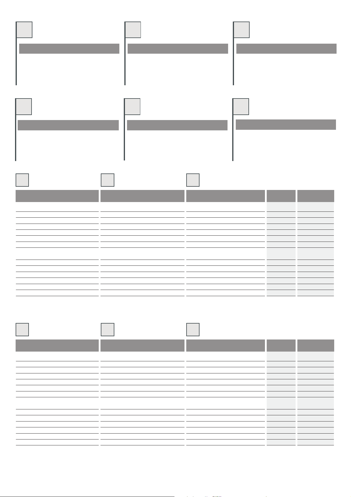
DATI TECNICI
Tensione di alimentazione
Encoder
Lunghezza massima anta
Peso massimo anta
Coppia nominale
Corrente max assorbita
Potenza max assorbita
Movimento
Angolo max. di rotazione
Tempo apertura 90°
Temperatura di funzionamento
Grado di protezione
Grasso motore
Intermittenza lavoro
* Possono variare in funzione del peso e
delle dimensioni dell'anta.
F
DONNÉES TECHNIQUES
Tension d'alimentation
Encodeur
Longueur maximum vantail
Poids maximum vantail
Couple nominal
Courant max. absorbé
Puissance max. absorbée
Mouvement
Angle max. de rotation
Temps d'ouverture 90°
Température de fonctionnement
Indice de protection
Graisse moteur
Intermittence travail
* Peuvent varier en fonction du poids et
des dimensions du vantail.
CARACTÉRISTIQUES
TEN2: Opérateur électromécanique réversible
pour portesbattantes.Alimentation 12Vcc avec
encodeuret brasarticulé
D
MERKMALE
TEN2: Elektromechanischer nicht
selbsthemmender Antrieb für Drehtore. 12VdcSpeisung mit Encoder, einschließlich
Gelenkarm.
E
DATOS TÉCNICOS
Tensión de alimentación
Encoder
Longitud máxima de la hoja
Peso máximo de la hoja
Par nominal
Corriente máx. absorbida
Potencia máx. absorbida
Movimiento
Ángulo máx. de rotación
Tiempo de apertura 90°
Temperatura de funcionamiento
Grado de protección
Grasa motor
Intermitencia de funcionamiento
* Pueden variar según el peso y las
dimensiones de la hoja.
CARACTERÍSTICAS
TEN2: Motorreductor electromecánico
reversible para hojas de batiente. Alimentación
12Vdc con Encoder, con brazo articulado
incorporado.
NL
KENMERKEN
TEN2: Omkeerbare elektromechanische
reductiemotor voor draaiende vleugels.
Stroomvoorziening 12Vdc met Encoder,
compleetmet geledearm.
U.M.
V 12dc
- Sì-Oui-Si
mm 1500
Kg 170
Nm 70
A5
VA 60
-
° 100°
Sec. 5*
°C -20+70
IP 44
- TS10
%60
TEN2
reversibile/Réversible
reversible
GB
D
TECHNICAL DATA TECHNISCHE DATEN
Power supply voltage
Encoder
Maximum leaf length
Maximum leaf weight
Nominal torque
Max. absorbed current
Max. absorbed power
Movement
Max. angle of rotation
90° opening time
Operating temperature
Protection rating
Motor oil
Duty cycle
* May vary according to the weight and
dimensions of the leaf
2
Versorgungsspannung
Encoder
Höchstlänge Torflügel
Höchstgewicht Torflügel
Nenndrehmoment
Höchststromaufnahme
Höchstleistungsaufnahme
Bewegung
Maximaler Drehwinkel
Öffnungszeit 90°.
Betriebstemperatur
Schutzart
Motorfett
Betriebsintermittenz
* Können sich aufgrund des Gewichts und
der Abmessungen des Torflügels ändern.
NL
TECHNISCHE GEGEVENS
Voedingsspanning
Encoder
Maximumlengte vleugel
Maximumgewicht vleugel
Nominale koppel
Max. opgenomen stroom
Max. opgenomen vermogen
Beweging
Max. draaihoek
Tijd opening 90°
Bedrijfstemperatuur
Beschermingsklasse
Motorvet
Bedrijfscyclus
* Dit kan variëren in functie van gewicht
en afmetingen van de vleugel.
U.M.
V 12dc
- Yes/Ja
mm 1500
Kg 170
Nm 70
A5
VA 60
-
° 100°
Sec. 5*
°C -20+70
IP 44
- TS10
%60
TEN2
reversible/Nicht selbsthemmend
omkeerbaar
Page 3
I F E
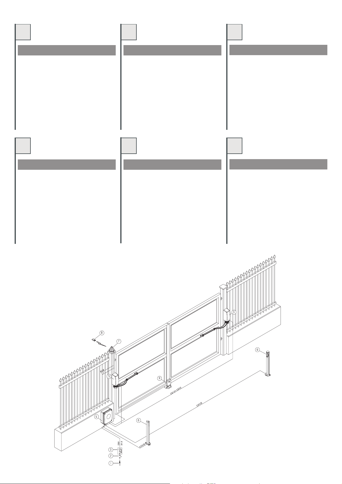
QUADRO D’INSIEME
1.Linea dialimentazione
2.Interruttore generale
3.Interruttore differenziale
4.Box concentralina
5.Motoriduttore TEN2
6.Fotocellule
7.Lampeggiatore 24V
8.Radiocomando
9.Elettroserratura (nonfornita)
VUE D'ENSEMBLE
1.Ligne d'alimentation
2.Interrupteur général
3.Disjoncteur différentiel
4.Coffret aveclogique de commande
5.Opérateur TEN2
6.Photocellules
7.Clignotant 24V
8.Radiocommande
9.Serrure électrique(non fournie)
DIBUJO DE CONJUNTO
1.Línea dealimentación
2.Interruptor general
3.Interruptor diferencial
4.Caja concentral
5.Motorreductor TEN2
6.Fotocélulas
7.Luz intermitente24V
8.Radiomando
9.Electrocerradura (nosuministrada)
GB D NL
OVERALL DIAGRAM GESAMTANSICHT
1.Power supplyline
2.Main switch
3.Differential switch
4.Box withcontrol unit
5.TEN2 gearmotor
6.Photocells
7.24V flashinglight
8.Radio control
9.Electric lock(not provided)
1.Versorgungsleitung
2.Hauptschalter
3.Differentialschalter
4.Box mitSteuerung
5.AntriebTEN2
6.Fotozellen
7.Blinklicht 24V
8.Funksteuerung
9.Elektroschloss (nichtmitgeliefert)
OVERZICHTSTEKENING
1.Elektriciteitsleiding
2.Hoofdschakelaar
3.Aardlekschakelaar
4.Box metbesturingseenheid
5.Reductiemotor TEN2
6.Fotocellen
7.Knipperlicht 24V
8.Draadloze bediening
9.Elektrisch slot(niet meegeleverd)
3
Page 4
I
F
E
VERIFICHE PRELIMINARI
Prima di passare all'installazione assicurarsi
che:
1. La struttura del cancello sia solida ed
appropriata.
2. Le cerniere di supporto dell'anta non
presentino segni di cedimento e/o
irregolarità.
3. Il movimento dell'anta durante tutta la corsa
siasenza puntid'attrito o vibrazioni.
4. La corsa dell'anta deve essere limitata, in
apertura ed in chiusura, da arresti rivestiti in
gommasaldamente fissatial suolo.
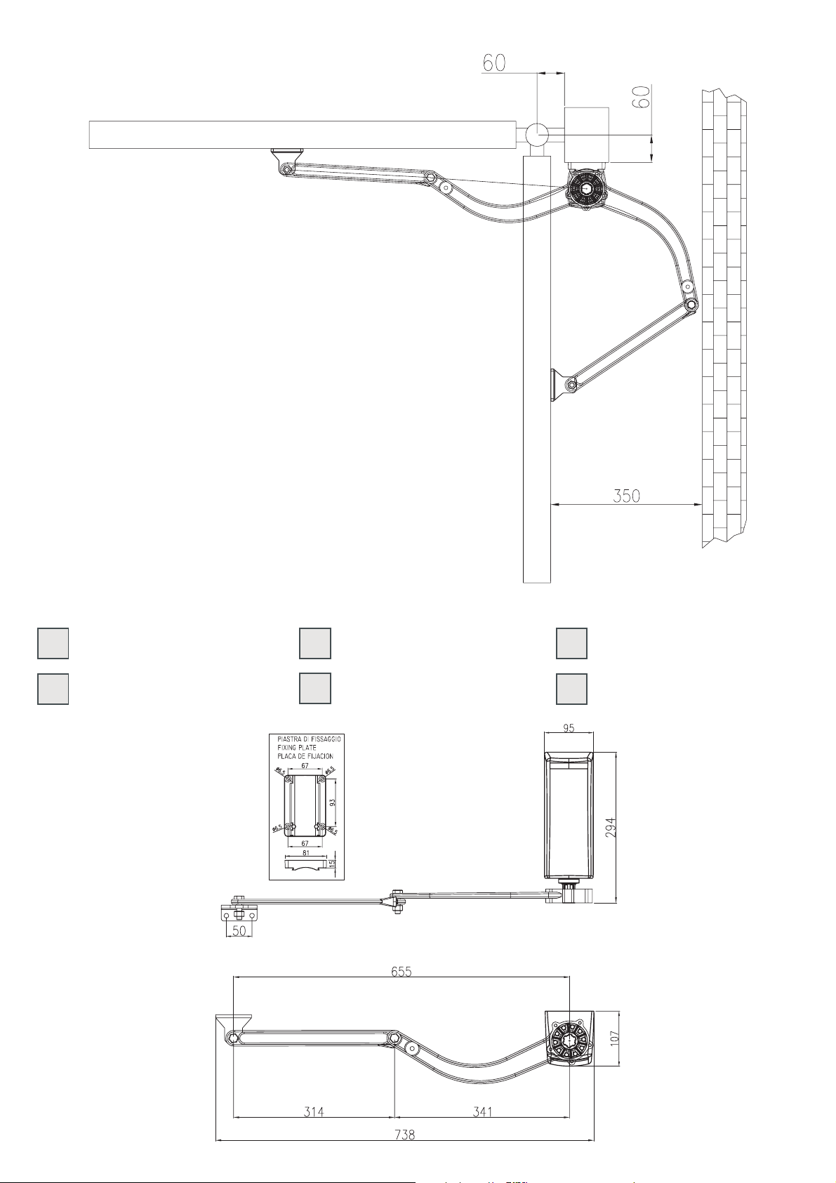
5. Lafigura sottostante indicale misure minime
entro cui si consiglia di utilizzare il
motoriduttore TEN2. E' consigliato non
abbassarsi mai sottola quota 60mm per non
pregiudicareil funzionamentodel motore.
NOTA: le misure sono indicative, solo per
preparare l'installazione. Verificare quale delle
possibili soluzionipuò essereapplicata al vostro
caso e provare manualmente l'applicazione
prima di procedere al fissaggio della piastra o
dellestaffe.
CONTRÔLES PRÉLIMINAIRES
Avantd'effectuer l'installation,s'assurerque:
1. Lastructuredu portailest solide et adaptée.
2. 2. Les charnières de support du vantail ne
présentent pas de signes d'usure et/ou ni de
défauts.
3. Le mouvement du vantail durant toute la
course ne présente aucun point de
frottementni devibration.
4. La course du vantail doit être limitée, en
ouverture et en fermeture, par des butées
revêtuesde caoutchoucsolidement fixéesau
sol.
5. La figure ci-dessous indique les mesures
minimum pour lesquelles on conseille
d'utiliser l'opérateur TEN2.Il est conseillé de
ne jamais descendre sous la mesure 60 mm
pour ne pascompromettre lefonctionnement
dumoteur.
NOTE: les mesures sont indicatives,
uniquement pour préparer l'installation. Vérifier,
parmi les solutions possibles, quelle est celle qui
s'applique à votre cas etessayer manuellement
l'application avant d'effectuer la fixation de la
plaqueet despattes.
CONTROLES PRELIMINARES
Antesde comenzarla instalación, controle que:
1. La estructura de la cancela sea firme y
adecuada.
2. 2. Las bisagras de soporte de la hoja no
tengan marcas de aflojamiento ni
irregularidades.
3. El movimiento de la hoja no tenga puntos de
fricción ni vibraciones durante toda su
carrera.
4. La carrera de la hoja debe estar limitada,
tanto en la apertura como en el cierre, por
topes revestidos de goma fijados
perfectamenteal suelo.
5. Lafigura de aquí abajo muestra las medidas
mínimas dentro de las cuales se aconseja
utilizar el motorreductor TEN2. Se aconseja
no instalarlo nunca a menos de 60 mm para
noperjudicar elfuncionamiento del motor.
NOTA: las medidas son indicativas sólo para
preparar la instalación. Controle las posibles
soluciones que puedan ser útiles para usted y
pruebe manualmentela aplicación antesde fijar
laplaca olos estribos.
GB
PRELIMINARY CHECKS
Beforeinstalling, checkthat:
1. Thegate'sstructure issuitable and robust.
2. The gate support hinges show no signs of
structuraldamage and/orirregularities.
3. No friction or vibrations occur at any time
duringthe movementof the gate.
4. The gate's travel must be delimited by
rubber-coatedstops firmlyfixed totheground
during both the opening and closing
manoeuvres.
5. The figure below shows the minimum
measurements within which use of gear
motor TEN2 is recommended. It is advisable
never to go below 60 mm so as not to
jeopardiseoperation ofthe motor.
NOTE: The measurements are guidelines only
and serve to prepare for installation. Check
which of thepossible solutions are applicable to
your specific case and test the application
manuallybefore fixingthe plate or brackets.
D NL
ÜBERPRÜFUNGEN UND
VORBEREITUNGEN
Vorder Installationist sicherzustellen,dass
1. DieTorstruktursolide undgeeignetist
2. DieScharniere, die dieTorflügel halten,keine
Anzeichen auf nachgebendes Material
und/oderUnregelmäßigkeiten aufweisen
3. Das Tor sich im gesamten Lauf ohne
Reibungenoder Vibrationenbewegt
4. Der Torlauf sowohl beim Öffnen als auch
beim Schließen durch mit Gummi
ummantelte Endanschläge begrenzt wird.
Die Anschläge müssen fest im Boden
verankertsein.
5. Die unten stehende Abbildung zeigt die
Mindestabmessungen an, mit denen der
Antrieb TEN2 benützt werden sollte. Wir
empfehlen, nie unter das Maß 60 mm zu
gehen, um die Funktionstüchtigkeit des
Motorsnicht zubeeinträchtigen.
Anmerkung: Die Maße sind unverbindlich und
dienen zur Vorbereitung der Installation. Es ist
zu überprüfen, welche der möglichen Lösungen
im konkreten Fall angewandt werden kann,
dazu wird die Anwendung zuerst manuell
ausprobiert, bevor die Platte oder die Bügel
befestigtwerden.
CONTROLES VOORAF
Voordatu met hetinstalleren begint, dientu zich
1. Destructuur van depoort is sterken voor het
2. De scharnieren van de steun van de vleugel
3. De vleugel tijdens de manoeuvre over de
4. De beweging van de vleugel wordt op de
5. Op de afbeelding hieronder staan de
N.B.: de afmeting vormen slechtseen aanwijzing
bij de voorbereiding voor de installatie. Ga na
welke oplossing van toepassing is op uw geval
en test deze handmatig uit voordat u de plaat of
de beugels gaatbevestigen.
vanhet volgendete vergewissen:
gebruiksdoelgeëigend.
vertonen geen tekenen van breuk en/of
onregelmatigheden.
gehele afstand van het traject geen
wrijvingspuntenof trillingenvertoont.
openings- en sluitpositie begrensd door van
een rubberen deklaag voorziene stops die
stevigop debodem zijn bevestigd.
minimumafmetingen waarbinnen de
reductiemotor TEN2 het best kan worden
gebruikt. Het is raadzaam nooit onder de 60
mm te komen om de goede werking van de
motor niet ingevaar tebrengen.
4
Page 5
I
MISURE D'INGOMBRO
F
DIMENSIONS D'ENCOMBREMENT
E
MEDIDAS EXTERIORES MÁXIMAS
GB
OVERALL DIMENSIONS
D
GESAMTABMESSUNGEN
NL
BUITENMATEN
5
Page 6
I
F E
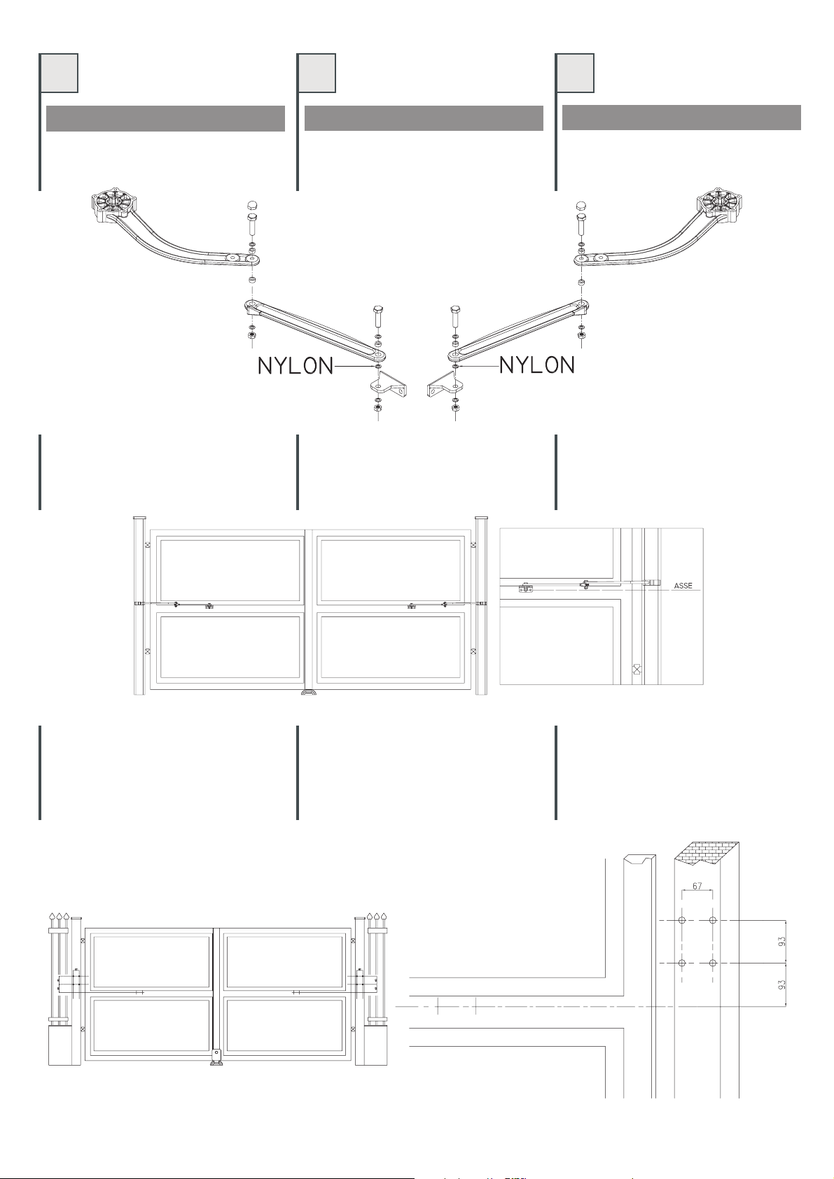
PROCEDURA DI MONTAGGIO
Assemblare il braccio articolato per un
montaggio a destra ea sinistradella viad'uscita.
FIG.1.
FIG.1 -ABB.1
Determinare laposizione dei bracciarticolati sui
traversi tracciando un asse orizzontale che
indichi il centro dei fori di fissaggio della staffa
anteriore– FIG.2.
PROCÉDURE DE MONTAGE
Assembler le bras articulé pour un montage à
droiteou àgauche du passage. FIG.1
Déterminer la position des bras articulés sur les
traverses en traçant un axe horizontal qui
indique lecentre destrous de fixation de lapatte
avant– FIG.2.
PROCEDIMIENTO DE MONTAJE
Ensamble elbrazo articulado paraun montaje a
derechay aizquierda de la víade salida.FIG.1
Determine la posición de los brazos articulados
en los travesaños, trazando un eje horizontal
que indique elcentro de los agujeros de fijación
delestribo delantero– FIG.2.
FIG.2 -ABB.2
Determinare quindi la posizione dei fori della
piastra di fissaggio per TEN2, tracciando sulla
colonna i rispettivi interassi a 93mm. Tracciare
quindi le distanze fra i rispettivi fori a 67mm–
FIG.3.
FIG.3 -ABB.3
Déterminer ensuite la position des trous de la
plaque de fixation pour TEN2, en traçant sur la
colonne les entraxesrespectifs à 93mm.Tracer
ensuite lesdistances entre les trousrespectifs à
67mm– FIG.3.
Posteriormente, determine la posición de los
agujeros de la placa de fijación para TEN2,
trazando enla columnalas distancias entre ejes
a 93 mm respectivamente. Trace las distancias
entrelos agujerosa 67 mm –FIG.3.
6
Page 7

GB
D NL
ASSEMBLY PROCEDURE
Assemble the articulated arm for right and left
fittingof theexit (Fig. 1).
FIG.1.- ABB.1- ABF. 1
Determine the positionof thearticulated arms on
the cross members by drawing a horizontal line
indicating the centre of the front bracket fixing
holes(Fig. 2).
MONTAGEVERFAHREN
Den Gelenkarm für eine Rechts- oder
Linksmontage des Ausgangswegs zusammensetzen.ABB. 1.
Die Position derGelenkarme inden Querträgern
mit einer waagrechten Achse bestimmen, die
das Zentrum der Befestigungsbohrungen des
vorderenBügels anzeigt–ABB. 2.
MONTAGEPROCEDURE
Assembleer de gelede arm om hem aan de
rechter- of linkerkant van de uitgang te
monteren.AFB.1.
Bepaal de plaats van de gelede armen op de
dwarsbalken en trek daarvoor een horizontale
lijn die het midden vande bevestigingsboringen
vande voorbeugelaangeeft –AFB.2.
FIG.2 -ABB.2 -ABF. 2
Now determine the position of the holes of the
fixing plate for TEN2 by marking the respective
centre-to-centre distances at93 mmon thepost.
Now markthe distances between therespective
holesat 67mm (Fig. 3).
FIG.3 -ABB.3 -ABF. 3
Dann die Position der Bohrung der Befestigungsplatte für TEN2 bestimmen, indem an der
Säule die jeweiligen Abstände von 93 mm
angezeichnet werden. Dann die Distanzen
zwischen den jeweiligen Bohrungen bei 67 mm
anzeichnen.ABB. 3.
Bepaal daarna de plaats van de boringen van de
bevestigingsplaat voor TEN2, waarvoor uop de
zuil de betreffende hartafstanden op 93 mm
aftekent. Teken daarna de afstanden tussen de
betreffendeboringen op67 mm af–AFB.3.
7
Page 8

I
F E
Scegliere il tipodi vitiadeguate almateriale della
colonna ed eseguire i quattro fori. Inserire due
dadi M6 sul retro della piastra di fissaggio –
FIG.4. Fissare con le viti prescelte, la piastra di
fissaggioalla colonnain posizione come FIG.5.
FIG.4 -ABB.4
Inserire il motoriduttore e bloccarlo con le viti
M6x90TCEI –FIG.6.
Choisir le type de vis adapté au matériau de la
colonne et percer4 trous.Introduire deux écrous
M6 sur l'arrière de la plaque de fixation – FIG.4.
Avec les vis choisies, fixer la plaque defixation à
lacolonne dansla position indiquée FIG.5.
Monter l'opérateur et le bloquer avec les vis
M6x90CHC –FIG.6.
Elija eltipo de tornilloadecuado para el material
de la columna y realice los cuatro taladros.
Coloque dos tuercas M6 en la parte trasera de la
placa de fijación– FIG.4. Fije con los tornillos la
placa de fijación a la columna, en la posición
indicadaen laFIG.5.
FIG.5 -ABB.5
Aplique el motorreductor y bloquéelo con los
tornillosAllen M6x90– FIG.6.
FIG.6 -ABB.6
8
Page 9

GB
DNL
Choose the type of screw suitable for the
material the post is made of and drill four holes.
Insert twoM6 nutsinto therear of the fixing plate
(Fig. 4). Use the screws to secure the fixing plate
tothe postin the position shownin Fig.5.
FIG.4 -ABB.4 -ABF. 4
Insert the gear motor and secure it using the
M6x90TCEI screws(Fig. 6).
Die für das Material der Säule geeignete
Schraubenart wählen und vier Bohrungen
ausführen. ZweiMuttern M6auf derRückseite der
Befestigungsplatte einsetzen – ABB. 4. Mit den
gewählten Schrauben die Befestigungsplatte an
die Säulein derPosition lautABB. 5befestigen.
Den Antrieb einsetzen und mit den Innensechskantzylinderkopfschrauben M6x90
befestigen.
Kies de voorhet materiaalvan dezuil geëigende
schroeven en boor de vier gaten. Breng twee
moeren M6 op de achterkant van de bevestigingsplaat aan – AFB.4. Bevestig de bevestigingsplaat met deschroeven opzijn plaatszoals
opAFB.5 tezien is.
FIG.5 -ABB.5 -ABF. 5
Plaats de reductiemotor en zet hem met de
schroevenM6x90 TCEI vast – AFB.6.
FIG.6 -ABB.6 -ABF. 6
9
Page 10

I
F E
Una volta fissato il motoriduttore, inserire il
braccio articolato sull'albero scanalato del
motore. Fissare con vite M8X15 TCEI e
rispettivarondella. –FIG.7.
FIG.7 -ABB.7
Après avoir fixé l'opérateur, introduire le bras
articulésur l'arbrecannelé dumoteur.Fixer avec
une vis M8X15 CHC et une rondelle. Bloquer
avecun goujonM8 – FIG.7.
Una vez fijado el motorreductor, introduzca el
brazo articulado en el eje acanalado del motor.
Fije con los tornillos Allen M8X15 y la arandela
correspondiente. Bloquee con un pasador de
M8– FIG.7.
A porta chiusa, posizionare il braccio articolato
al massimo della sua estensione, sul traverso
dell'anta. Segnare la posizione dei fori, quindi
foraree fissarecon viti adeguate. FIG.8.
FIG.8 -ABB.8
Avec la porte fermée, positionner le bras articulé
dans son extensionmaximum, surla traversedu
vantail Marquerla position des trouspuis percer
etfixer avecdes vis appropriées. FIG.8.
Con la puerta cerrada, coloque el brazo
articulado en su extensión máxima en el
travesaño de la hoja. Marque la posición de los
agujeros, taladre y fije con los tornillos
adecuados.FIG.8
10
Page 11

GB
DNL
After securing the gear motor, fit the articulated
arm ontothe motor's splined shaft. Fastenusing
aM8X15 TCEIscrew and washer. (Fig.7).
FIG.7 -ABB.7 -ABF.7
Nachdem der Antrieb befestigt wurde, den
Gelenkarm an der Keilwelle des Motors
einsetzen. Mit Innensechskantzylinderkopfschraube M8x15 und diesbezüglicher
Scheibebefestigen. ABB. 7befestigen.
Wanneer de reductiemotor is bevestigd, brengt
u de geledearm opde vangroeven voorziene as
van de reductiemotor aan. Bevestig deze met
schroefM8X15 TCEIplus borgring. AFB.7.
With the gate closed, position the articulated
arm at its point of maximum extension on the
gate crossbeam. Mark the position of the holes,
thendrill andfasten with suitable screws(Fig. 8).
FIG.8 -ABB.8 -ABF.8
Bei geschlossener Tür, den Gelenkarm auf
seine weiteste Ausdehnung am Querträger des
Flügels bringen. Die Position der Bohrungen
anzeichnen, dann bohren und mit den geeignetenSchrauben befestigen(ABB. 8).
Plaats bij gesloten deur de gelede arm zo ver
mogelijk uitgestrekt op de dwarsbalk van de
vleugel.Tekende plaats van de gatenaf, boorze
enbevestig zemet de juiste schroeven.AFB.8.
11
Page 12

I
F E
MONTAGGIO ELETTROSERRATURA
(NON FORNITA)
I motoriduttori della serie TEN2 sono di tipo
reversibile con braccio articolato autobloccante. Se si desiderasse montare
un'elettroserratura, nelle fig. 9 e 10 sono
raffigurati due esempi d'installazione più
comuni. Si raccomanda di rispettare tassativamentele quoteriportate in dette figure.
Eseguire tutti i cablaggi come riportato nel
manualeE224.
MONTAGE SERRURE ÉLECTRIQUE
(NON FOURNIE)
Les opérateurs de la série TEN2 sont de type
réversible avec bras articulé autobloquant. Si
l'ondésire monterune serrure électrique,les fig.
9et 10illustrent deux exemples d'installationles
plus courants. Nous recommandons de
respecter impérativement les mesures
indiquéesdans lesfigures susdites.
Effectuer tous les câblages suivant les
indicationsdu noticed'instrucciones E224.
MONTAJE DE LA ELECTROCERRADURA
(NO SUMINISTRADA)
Los motorreductores de la serie TEN2 son tipo
reversible, con brazo articulado autoblocante.
Si se deseara montar una electrocerradura, en
las figs. 9 y 10 se muestran dos ejemplos de
instalación más comunes. Se recomienda
respetar las medidas indicadas en dichas
figuras.
Pase todos los cables tal como indicado en
elmanual E224.
FIG.9 -ABB.9 FIG.10 -ABB.10
INSERIRE IL COPERCHIO COLOQUE LA TAPA
Una volta eseguiti tutti i cablaggi e la messa in
funzione dell'impianto, inserire il coperchio e
bloccarlocon viteFIG.13.
REMONTER LE COUVERCLE
Une fois que tous les câblages ont été effectués
et que l'installation a été mise en service,
remonter le couvercleet lebloquer àl'aide d'une
visFIG.13
Cuando haya cableado todo y puesto en
funcionamiento la instalación, coloque la tapa y
bloquéelacon lostornillos FIG.13.
FIG.13 -ABB.13
12
Page 13

GB
DNL
FITTING ELECTRIC LOCK
(NOT PROVIDED)
The TEN2 series gear motors are of the
reversible type withself-locking articulatedarm.
If you wish to fit an electric lock, Figs. 9 and 10
show two examples of common installations. It
is most important to observe the distances
indicatedin thesefigures.
Carry out all the wiring workas described in
themanual E224.
MONTAGE ELEKTROSCHLOSS
(NICHT MITGELIEFERT)
Die Antriebe der Serie TEN2 sind nicht
selbsthemmend und weisen einen selbstsperrenden Gelenkarm auf. Wenn ein Elektroschloss montiert werden soll, zeigen die
Abb. 9 und 10 die zwei üblichsten Installationsbeispiele. Die Maße in den genannten
Abbildungensind unbedingteinzuhalten.
Alle Verkabelungen wie im bedienungsanleitungE224 gezeigtausführen.
MONTAGE ELEKTRISCH SLOT
(NIET MEEGELEVERD)
De reductiemotoren van de serie TEN2
behoren tot het omkeerbare type met zelfblokkerende gelede arm.Indien ueen elektrischslot
zou willenmonteren, vindt u op afb.9 en 10 een
voorbeeld van de twee meeste voorkomende
manieren van installatie. Wij raden u aan de op
deze afbeeldingen aangegeven waarden
nauwgezetin achtte nemen.
Voer de bekabeling uit zoals dat in handleidingE224 isaangegeven.
FIG.9 -ABB.9 -ABF.9 FIG.10 -ABB.10 -ABF.10
FIT COVER
After completing the wiring and start-up the
system, fit the cover and secure it with a screw
(Fig.13).
DEN DECKEL EINSETZEN
Nachdem alle Verkabelungen und die
Inbetriebnahme der Anlage ausgeführt wurden,
den Deckel einsetzenund mit der Schraube der
ABB.13 befestigen.
AANBRENGEN VAN DE DEKPLAAT
Wanneer alle kabels zijn aangebracht en de
installatie in bedrijf is gesteld, brengt u de
dekplaat aan en zet hem met de schroef vast
afb.13.
FIG.13 -ABB.13 -ABF.13
13
Page 14

I
F
E
FUNZIONAMENTO MANUALE
I motoriduttori della serie TEN2 sono di tipo
reversibile con braccio articolato autobloccante. In caso d'assenza d'elettricità, si può
intervenire manualmente per aprire e chiudere
l'anta pedonale sbloccando l'elettroserratura
(se presente) etirando versose stessi ilbraccio.
Agirepoi sull'antaper un'apertura totale FIG.14.
FIG.14 -ABB.14
FONCTIONNEMENT MANUEL
Les opérateurs de la série TEN2 sont de type
réversible avec bras articulé autobloquant. En
cas de coupure de courant, on peut intervenir
manuellement pour ouvrir et fermer la porte
piétonne en débloquant la serrure électrique(si
elle est présente) et en tirant vers soit le bras.
Agir ensuite sur le vantail pour une ouverture
totaleFIG.14.
FUNCIONAMIENTO MANUAL
Los motorreductores de la serie TEN2 son tipo
reversible, con brazo articulado autoblocante.
Si no hubiera corriente eléctrica, para abrir y
cerrar la hojapara peatonesse puedeintervenir
manualmente desbloqueando la electrocerradura (en su caso) y tirando hacia usted del
brazo. Posteriormente, mueva la hoja para
abrirlatotalmente FIG.14.
ANOMALIE E RIMEDI PROBLEMAS Y SOLUCIONES
Il motoriduttore non apre, o non chiude, il
motore elettrico nonfunziona, nonsi avverte
alcunrumore ovibrazione.
a. Verificare che la centralina elettronica di
comando sia regolarmentealimentata eche i
fusibilisiano efficienti.
b Accertarsi che icollegamenti sianoesatti.
Il motoriduttore aprea scatti,ma nonavviene
ilmovimento completo.
a. Assicurarsi che la regolazione della velocità
sullacentralina siacorretta;
b. Assicurarsi che non visiano impedimenti nel
movimentodell'anta.
c. Controllare il giusto cablaggio dei cavi
encoder.
Il motoriduttore esegue la manovra inversa
(chiusurainvece diapertura).
a. Invertirefra loroifili difase delmotore.
14
ANOMALIES ET REMÈDES
L'opérateur n'ouvre pas ou ne ferme pas, le
moteur électrique ne fonctionne pas, on
n'entendaucun bruitni vibration.
a. Vérifier que la logique de commande
électronique est correctement alimentée et
queles fusiblessont intacts.
b.S'assurer queles connexions sont exactes.
L'opérateur ouvre par à-coups, mais le
mouvementreste incomplet.
a. S'assurer que le réglage de la vitesse sur la
logiquede commandeest correct.
b. S'assurer qu'aucun obstacle ne gêne le
mouvementdu vantail.
c. Contrôler que le câblage de l'encodeur est
correct.
L'opérateur effectue la manœuvre inverse
(fermetureau lieud'ouverture).
a Intervertir lesfils dephasedu moteur.
El motorreductor no abre ni cierra, el motor
eléctrico no funciona, no se advierte ningún
ruidoni vibración.
a. Controleque lacentral electrónica demando
esté bien alimentada y que los fusibles sean
eficientes.
b. Asegúrese de que las conexiones sean
exactas.
El motorreductor abre por impulsos pero el
movimientono secompleta.
a. Asegúrese de que la regulación de la
velocidaden lacentral sea correcta;
b. Controle que la hoja no tenga ningún
obstáculoque impidasu movimiento.
c. Controle que los cables del encoder estén
bienconectados.
El motorreductor hace la maniobra inversa
(cierraen lugarde abrir).
a. Inviertaentresí loscables de fase delmotor.
Page 15

GB
DNL
MANUAL OPERATION
The TEN2 series gear motors are of the
reversible type withself-locking articulatedarm.
In the absenceof electricity, thepedestrian gate
can be opened and closed manually by
releasing the electric lock using the key (if
provided) and pulling the arm towards you.
Movethe gateto open it completely(Fig. 14).
FIG.14 -ABB.14 -ABF.14
MANUELLER BETRIEB
Die Antriebe der Serie TEN2 sind nicht
selbsthemmend und weisen einen selbstsperrenden Gelenkarm auf. Bei Stromausfall kann
von Hand eingegriffen werden, um den
Gehflügel zu öffnen und zu schließen, indem
das Elektroschloss (wenn vorhanden) gelöst
und der gebogene Arm zu sich gezogen wird.
Dann auf den Flügel einwirken, um eine
vollständige Öffnung – laut ABB. 14 – zu
erreichen.
HANDMATIGE BEDIENING
De reductiemotoren van de serie TEN2
behoren tot het omkeerbare type met zelfblokkerende gelede arm. In geval van stroomuitval
kunt u de voetgangersvleugel handmatig
openen en sluiten door het elektrische slot
(indien aanwezig) te ontgrendelen en de
gebogen arm naar zich toe te trekken. Open de
vleugeldaarna helemaal,AFB.14.
PROBLEM SOLVING STORINGEN EN OPLOSSINGEN
The gear motor does not open or does not
close, the electric motor does not work, and
nonoise orvibration can be felt.
a. Check that the electronic control unit is
powered correctly and that the fuses are
working.
b. Makesurethat theconnections are correct.
The gearmotor openshaltingly anddoes not
performthe completemovement.
a. Make sure that the speed setting on the
controlunit iscorrect.
b. Make sure there is nothing obstructing the
movementof thegate.
c. Check that the encoder cables are wired
correctly.
The gear motor performs the reverse
operation(closing insteadof opening).
a. Invertthemotor's phasewires.
STÖRUNGEN UND ABHILFEN
Der Antrieb öffnet und schließt nicht, der EMotor funktioniert nicht und man bemerkt
daherweder einGeräusch noch Vibrationen.
a. Sicherstellen, dass die elektronische
Steuerung ordnungsgemäß gespeist wird
unddie Sicherungenfunktionstüchtig sind.
b. Sicherstellen, dass die Anschlüsse richtig
sind.
Der Antrieb öffnet ruckweise, aber es erfolgt
keinevollständige Bewegung.
a.Sicherstellen, dass die
Geschwindigkeitseinstellung in der
Steuerungkorrekt ist.
b. Sicherstellen, dass keine Hindernisse die
Bewegungdes Torflügelsstören.
c. Diekorrekte Verkabelung derEncoder-Kabel
prüfen.
Der Antrieb führt die umgekehrte Bewegung
aus(Schließung stattÖffnung).
a. DiePhasenleiterdes Motorsumkehren.
De poortgaat opennoch dicht,de elektromotor
werktniet, eris geenenkelgeluid oftrilling
a. Controleer of de elektronische
besturingseenheid naar behoren van stroom
wordtvoorzien enof dezekeringenintact zijn.
b. Controleer of de aansluitingen juist zijn
uitgevoerd.
De reductiemotor gaat met horten open, maar
erwordt geencomplete manoeuvreuitgevoerd.
a. Vergewis u ervan dat de snelheid juist is
afgesteldop debesturingseenheid;
b. Vergewis u ervan dat de vleugel niet in zijn
bewegingwordt gehinderd.
c. Controleer of de bekabeling van de
encoderkabelsjuist isuitgevoerd.
De reductiemotor voert de tegengestelde
manoeuvreuit (sluitingin plaatsvanopening).
a. Verwissel de fasedraden van de motor met
elkaar.
15
Page 16

IFE
SMALTIMENTO MISE AU REBUT ELIMINACIÓN
Questo prodotto è formato da vari
componenti che potrebbero a loro volta
contenere sostanze inquinanti. Non
disperdere nell'ambiente! Informarsi sul
sistema di riciclaggio o smaltimento del
prodotto attenendosi alle norme di legge
vigentia livellolocale.
Ce produit est constitué de divers
composants qui pourraient à leur tour
contenir des substances polluantes. Ne
pas jeter dans la nature !S'informer sur le
système de recyclageou demise aurebut
du produit en respectant les normes
localesen vigueur.
Este producto está formado de varios
componentes que, a su vez, podrían
contener sustancias contaminantes. ¡No
los abandone en el medio ambiente!
Infórmese sobre el sistema de reciclaje o
eliminación del producto, respetando las
normasvigentes locales.
GB D NL
DISPOSAL ENTSORGUNG AFVALVERWERKING
This product consists of various
components which may contain polluting
substances. Do not release to the
environment! Find out about the
procedures for recycling or disposing of
the product in accordance with locally
applicablelaws.
Dieses Produkt besteht aus
verschiedenen Bestandteilen, die
Schadstoffe enthalten könnten. Nicht in
der Umwelt wegwerfen! Informieren Sie
sich über die Systeme zum Recycling
oder zur Entsorgung des Produkts und
halten Sie sich an die örtlich geltenden
Vorschriften.
Dit product bestaat uit verschillende
onderdelen die op hun beurt
verontreinigende stoffen zouden kunnen
bevatten. Laatze niet inhet milieu achter!
Win inlichtingen in over het
recyclingsysteem of over de
afvalverwerking van het product en houd
u aande wettelijke voorschriften zoals die
inuw landvan toepassing zijn.
16
Page 17

17
Page 18

IFE
DICHIARAZIONE CE DÉCLARATIONS CE
Il fabbricante: Telcoma srl - Via L. Manzoni, 11 31015 - Z.I.
Campidui- Conegliano(TV) -ITALY
DICHIARA che il prodotto è conforme alle condizioni delle
seguenti direttive CEE:
93/68/EECLow Voltage
Directive89/336/EEC, Directive92/31/EEC
Directive92/31/EEC ElectromagneticCompatibility
e che: sono state applicate le seguenti (parti/clausole) di
norme armonizzate:
3,EN61000-6-1
andfor theonly applicableparts thenorms
EN12445e EN12453
Directive 73/23/EEC, Directive
EN60335-1, EN60204-1, EN 61000-6-
DICHIARAZIONE DEL
Lefabricant: Telcomasrl
Via L. Manzoni 11, Z.I. Campidui - 31015 Conegliano (TV)
ITALIE, DÉCLARE que le produit est conforme aux
conditionsdes directivesCEE suivantes:
Directive73/23/EEC, Directive93/68/EEC LowVoltage
Directive89/336/EEC, Directive92/31/EEC
Directive92/31/EEC ElectromagneticCompatibility
et que les (parties/clauses) de normes harmonisées
suivantesont étéappliquées:
EN60335-1,EN60204-1, EN61000-6-3, EN61000-6-1
andfor theonly applicableparts thenorms
EN12445e EN12453
DÉCLARATION DU FABRICANT DECLARACIÓN DEL FABRICANTE
FABBRICANTE
(Direttiva98/37 CEEAllegato II,Parte B)
Il prodottoè costruito peressere incorporati inuna macchina
o per essere assemblati con altri macchinari per costruire
unamacchina consideratadalla Direttiva98/37 CEE
E inoltre dichiara che non è consentito mettere in servizio il
prodottofino achela macchinain cuisaranno incorporatio di
cuidiverranno componentisiastata identificatae nesia stata
dichiarata la conformità alle condizioni della Direttiva 98/87
CEE e allalegislazione nazionale chelo traspone, valeadire
fino a che il prodotto di cui alla presente dichiarazione non
formiun complessounico conla macchinafinale.
Conegliano,lì
Legalrepresentative
AugustoSilvio Brunello
22/10/2008
(Directive98/37 CEEAnnexe II,Partie B)
Le produit est construit pour être incorporé dans une
machine ou pour être assemblé avec d'autres machines
pour constituer une machine couvertepar la Directive98/37
CEE.
Il déclare également qu'ilest interdit de mettre en service le
produit tantque lamachine danslaquelle il seraincorporé ou
dont il deviendra un composant n'a pas été identifiée et
déclarée conformeaux conditionsde laDirective 98/87 CEE
et àla législation nationalequi la transpose,c'est-à-dire tant
que le produitobjet de la présente déclaration ne forme pas
unensemble uniqueavec lamachine finale.
Conegliano,le
Legalrepresentative
AugustoSilvio Brunello
22/10/2008
DECLARACIÓN DE CONFORMIDAD CE
Elfabricante: Telcomasrl
Via L.Manzoni, 11 31015- Z.I.Campidui -Conegliano (TV)ITALIA - DECLARA que el producto es conforme a las
condiciones de las siguientes directivas CEE:
73/23/EEC,Directive 93/68/EECLow Voltage
Directive89/336/EEC, Directive92/31/EEC
Directive92/31/EEC ElectromagneticCompatibility
y que:se hanaplicado las siguientespartes/cláusulas delas
normas armonizadas:
6-3,EN61000-6-1
andfor theonly applicableparts thenorms
EN12445e EN12453
(Directiva98/37 CEEAnexo II,Parte B)
El producto ha sido fabricado para ser incorporado en una
máquina o para ser ensamblado con otras máquinas para
construir una máquina considerada por la Directiva 98/37
CEE
También declara que no está permitido poner en
funcionamiento el producto hasta que la máquina en que
seránincorporados oala quepertenecerán, seaidentificada
y sea declarada de conformidad con las condiciones de la
Directiva 98/87CEE ycon la legislaciónnacional vigente,es
decir hasta que el producto al que se refiere esta
declaración,forme ungrupo únicocon lamáquina final.
Conegliano,
Legalrepresentative
AugustoSilvio Brunello
EN60335-1, EN60204-1, EN 61000-
22/10/2008
Directive
GB D NL
EC DECLARATION EG-ERKLÄRUNG EG-VERKLARING
Themanufacturer: Telcomasrl
Via L.Manzoni, 11 31015- Z.I.Campidui -Conegliano (TV)ITALY - DECLARES that the product complies with the
requirements of the following EEC directives:
73/23/EEC,Directive 93/68/EECLow Voltage
Directive89/336/EEC, Directive92/31/EEC
Directive92/31/EEC ElectromagneticCompatibility
and that: the following parts/clauses of harmonised
standards havebeen adopted:
61000-6-3,EN61000-6-1
andfor theonly applicableparts thenorms
EN12445e EN12453
EN60335-1, EN60204-1,EN
Directive
MANUFACTURER'S
DECLARATION
(Directive98/37 EECAnnex II,Part B)
Theproduct isdesignedto beincorporated ina machineor to
be assembled with other machinery to make up a machine
consideredby theDirective 98/37EEC.
It also declaresthat the product mustnot be put intoservice
until the machinery in which it is to be incorporated or of
which it is to become a component has been identified and
declared inconformity withthe Directive 98/87EEC andwith
the national legislationthat enacts it, in other words untilthe
product referredto inthis declarationforms a singleunit with
thefinal machinery.
Conegliano,
Legalrepresentative
AugustoSilvio Brunello
22/10/2008
Der Hersteller:TELCOMA S.r.l. - Via L.Manzoni, 11 31015 Z.I. Campidui - Conegliano (TV) - ITALY - ERKLÄRT, dass
das Produkt den Vorschriften der folgenden EWGRichtlinien entspricht:
93/68/EECLow Voltage
Directive89/336/EEC, Directive92/31/EEC
Directive92/31/EEC ElectromagneticCompatibility
und dass die folgenden zugehörigen Normen
(Teile/Klauseln) angewendet wurden:
EN60204-1,EN 61000-6-3,EN61000-6-1
andfor theonly applicableparts thenorms
En12445e En12453
Directive 73/23/EEC, Directive
EN60335-1,
De fabrikant: Telcoma srl - Via L. Manzoni, 11 31015 - Z.I.
Campidui- Conegliano(TV) -ITALY
VERKLAART dathet product in overeenstemming ismet de
voorwaarden van de volgende EEG-richtlijnen:
73/23/EEC,Directive 93/68/EECLow Voltage
Directive89/336/EEC, Directive92/31/EEC
Directive92/31/EEC ElectromagneticCompatibility
en dat: zijntoegepast de volgende (delen/clausules)van de
geharmoniseerde normen:
61000-6-3,EN61000-6-1
andfor theonly applicableparts thenorms
EN12445e EN12453
ERKLÄRUNG DES HERSTELLERS VERKLARING VAN DE FABRIKANT
(Richtlinie98/37 EWGAnlage II,TeilB)
Das Produkt wurde gebaut, um in eine Maschine integriert
oder um mit anderen Maschinen zusammengebaut zu
werden, um eine Maschine laut Richtlinie 98/37 EWG zu
bilden.
Außerdem erklärt er, dass das Produkt nicht in Betrieb
genommenwerden darf,bisdie Maschine,in diees integriert
wird oder deren Teil es wird, identifiziert und gemäß der
Richtlinie 98/37 EWG und dernationalen Gesetzgebung als
konform erklärt wird, d.h. bis das Produkt dieser Erklärung
nicht eine einzige Gruppe mit der endgültigen Maschine
bildet.
Conegliano,den 22/10/2008.
Legalrepresentative
AugustoSilvio Brunello
(Richtlijn98/37EEGBijvoegselII,Deel B)
Dit productis gemaaktom ineen machineingebouwd teworden of
met andere machines geassembleerd te worden teneinde een
machine te vormen op grond van de Richtlijn 98/37/ EEG En
bovendienverklaarthijdat hetniet geoorloofdis ditproduct inbedrijf
te stellen zolangde machine waarin de onderdelenzullen worden
ingebouwd of waarvan zij een onderdeel zullen vormen niet
geïdentificeerd is en waarvoor niet verklaard is dat die in
overeenstemming is met de voorwaarden van de Richtlijn 98/87
EEG enmet de nationalewetgeving, waarin diegeïmplementeerd
is, dat wil zeggen zolang het product onderwerp van deze
verklaringnietééngeheelvormtmet deuiteindelijke machine.
Conegliano,
Legalrepresentative
AugustoSilvioBrunello
22/10/2008.
Directive
EN60335-1, EN60204-1, EN
18
Page 19

NOTE
19
Page 20

CERTIFICATO DI GARANZIA
PRODOTTO
TIMBRO E/O FIRMA DELL’INSTALLATORE
DATA D’INSTALLAZIONE
%
IFE
GARANZIA GARANTIE GARANTÍA
La presentegaranzia copre gli eventualiguasti e/oanomalie
dovuti a difetti e/ovizi di fabbricazione. La garanzia decade
automaticamente in caso di manomissione o errato utilizzo
delprodotto.
Durante ilperiodo digaranzia, la dittaTelcoma srls'impegna
a riparare e/o sostituire leparti difettate e non manomesse.
Restano a intero ed esclusivo carico del cliente il diritto di
chiamata, nonché le spese dirimozione, imballo etrasporto
delprodotto perla riparazionee sostituzione.
La présentegarantie couvreles pannes et/oules anomalies
éventuelles duesà desdéfauts et/ouvices defabrication. La
garantie cesse automatiquement encas de modification ou
d'utilisationincorrecte duproduit.
Durant la période de garantie, la société TELCOMA S.r.l.
s'engage à réparer et/ou à remplacer les parties
défectueuses etnon modifiées.Le forfaitdéplacement,ainsi
que les fraisderetrait, d'emballageetde transportdu produit
pour la réparation ou le remplacement restent entièrement
etexclusivement àla chargedu client.
La presente garantía cubre las averías o anomalías
provocadas pordefectos o vicios defabricación. Lagarantía
pierde automáticamente validez en el caso de
modificacioneso usoincorrecto delproducto.
Durante el período de garantía, Telcoma srl se obliga a
reparar y/o sustituir las piezas defectuosas yque no hayan
sido modificadas. Quedana cargo del clienteel derecho de
llamada y los gastos de desmontaje,embalaje y transporte
delproducto parasu reparacióny sustitución.
*
GB D NL
WARRANTY GARANTIE GARANTIE
This warranty covers faults and malfunctions caused by
manufacturing defects. The warranty is automatically
invalidated in the event of tampering or improper use of the
product.
During the warranty period the company Telcoma srl
undertakes torepair or replacedefective partsthat have not
been tampered with. Call-out charges along with expenses
of removal,packaging andtransport ofthe productfor repair
orreplacement areto bepaid bythe customer.
Die vorliegende Garantie gilt für eventuelle Defekte
und/oder Störungen aufgrund von Fabrikationsfehlern
und/oder -mängeln, Die Garantie wird im Falle von
Handhabung oder falscher Benutzung des Produktes
automatischungültig.
In der Garantiezeit verpflichtet sich die Firma TELCOMA
S.r.l. zur Reparatur und/oder zum Ersatz defekter und nicht
manipulierter Teile. Ausschließlich und voll zu Lasten des
Kunden gehen die Abrufgebühr sowie die Kosten für die
Demontage, die Verpackung und den Transport des
Produktsim Falleeiner Reparaturoder einesErsatzes.
Telcoma srl - Via L. Manzoni, 11 - Z.I. Campidui
31015 Conegliano - (TV) Italy - Tel. +39 0438-451099
Fax +39 0438-451102 - Part. IVA 00809520265
http://www.telcoma.it E-mail: info@telcoma .it
Met deze garantie worden eventuele defecten en/of
storingen gedekt die het gevolg zijn van een gebrekkige of
ondeugdelijke constructie. De garantie komt automatisch te
vervallen in geval van onrechtmatige wijzigingen aan of
onjuist gebruik van het product. Tijdens de garantieperiode
verplicht de firmaTelcoma zich gebrekkige enongewijzigde
delen te repareren en/of te vervangen. De voorrijkosten
alsook kosten voorverwijdering, verpakking envervoer van
het product in verband met reparatie en vervanging komen
geheelen uitsluitendten lastevan deklant.
 Loading...