

Page 1
- Data Brochure
D 362
Mixing Control 362
12/08
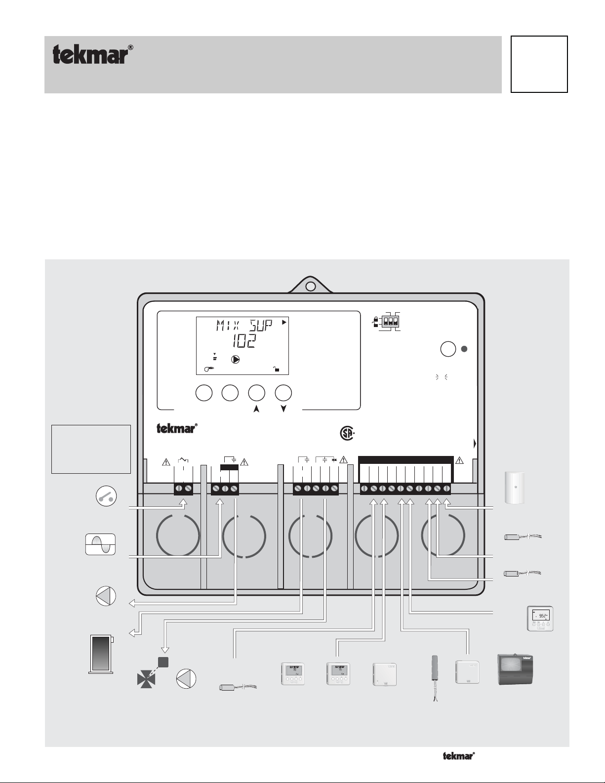
The Mixing Control 362 is a microprocessor based control with two distinct operating modes.
MODE —1— allows the control to provide a reset mixed supply water temperature to a heating system based on outdoor air temperature.
Multiple zone temperature controls can be achieved by using either a conventional thermostat system or by using tekmar Zone Controls
attached to the 362. For single zone heating applications, a single Room Temperature Unit (RTU) can be connected directly to the 362
for zone temperature control.
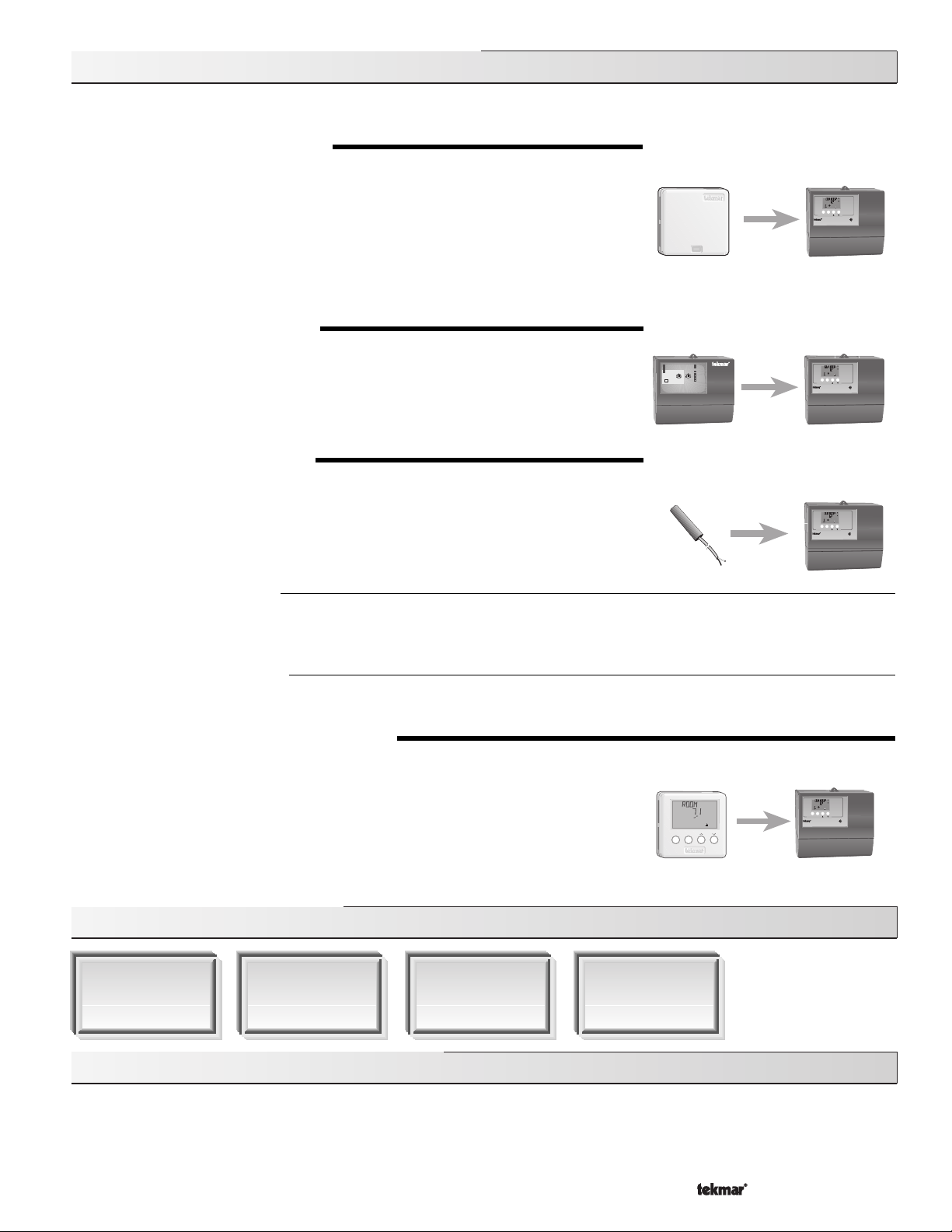
MODE —2— allows the control to provide a single zone of snow melting. With the addition of a Snow Melting Kit 092, the 362 can
provide slab temperature control and slab ΔT protection. The melting mode is initiated manually either with a demand signal or from the
Snow Melting Kit enabling device.
The 362 incorporates a large Liquid Crystal Display (LCD) in order to provide system status and operating information. The same LCD
is used when setting up and installing the control. Standard features for both modes of operation include boiler return protection,
intelligent boiler operation, Warm Weather Shut Down (WWSD), and pump exercising. As well, with the addition of a new Monitor
feature, it is now possible to track pump and boiler running hours, boiler cycles and high and low sensor temperatures. The 362 also has
a unique feature that allows the control to supply heat to the mixed system from either the boiler or a thermal storage tank.
1 Heating
2 Snow melting
Do not apply power
13
14
tN1/
Com1510K16UnO
tN2
Reset Ratio
Characterized
Heating Curve
17
Com
Sw
Te s t
off
off
red
red
For maximum heat,
press and hold
button for 3 seconds.
18
Mix19Boil20Out
not testing
not testing
testing
testing
testing pausedred
Tes t
Meets Class B:
Canadian ICES
FCC Part 15
Date Code
H1176D
Note:
Mixing demand must be
powered with 20 to 260
V (ac) before the mixing
valve is able to open and
the boiler is able to fire.
View
Open
%
1
Item
Menu
Mixing Control 362
Floating Action / Variable Speed
5
4
3
2
1
Mix
Demand
Power
N L
Pmp
Mix
°
UnOcc
Mix Demand
F
WWSD
Minimum
Maximum
Melting
Idling
7
9
6810
Pwr
Opn Cls
Boiler
Mix
Var
C US
Setback
None
Operating Modes
See product literature
INSTALLATION CATEGORY II
Made in Canada by
tekmar Control Systems Ltd.
tektra 929-04
Power 115 V ±10% 60 Hz 900 VA
R
Relays 230 V (ac) 7.5 A 1/3 hp, pilot duty 240 VA
Var. Pump 230 V (ac) 2.4 A 1/6 hp, fuse T2.5 A 250V
Demands 20 to 260 V (ac) 2 VA
Signal wiring must be rated at least 300 V.
Wiring must be rated 194°F (90°C) minimum
11 12
Com Mix
Ret
Input
Mix Demand
Signal
120 V (ac) Power
Input
Supply
Output
Mixing System
Pump
Output
M
OR
Output
Mixing Valve & Actuating
Motor OR Var. Speed
Driven Pump
Input
Universal
View
F
°
WWSD
1%%2
!
ItemMenu
Input
Room
Temperature
Unit (RTU)
1 of 36
View
F
°
WWSD
1%%2
!
ItemMenu
OR OR
Input
Remote
Display
Module (RDM)
79
8
Input
Snowmelt
Kit
(SMK)
Input
Outdoor
Input
Universal
Input
Universal
Sensor
Input
tekmar
Timer
LR 58233
OR OR
70
tekmar Slab Sensor or Indoor Sensor or
Input
Zone Control
E150539
Copyright © D 362 -12/08
Included
Page 2
How To Use The Data Brochure
This brochure is organized into four main sections. They are: 1) Sequence
Troubleshooting
Sequence of Operation
apply to your installation.
Control Settings
The
by the control. The control functions of each adjustable item are described in the
. The
Sequence of Operation
, as this contains important information on the overall operation of the control. Then read to the sub sections that
section (starting at DIP Switch Settings) of this brochure describes the various items that are adjusted and displayed
section has four sub sections. We recommend reading
of Operation
Table of Contents
User Interface ........................................... pg 2
Description of Display Elements ............ pg 3
Sequence of Operation ........................... pg 4
Section A: General
Section B: Mixing Reset
Section C: Snow Melting
Section D: Boiler Operation
Installation ................................................ pg 15
Electrical Connections.................. pg 16
Testing The Wiring......................... pg 18
DIP Switch Settings ................................. pg 20
........................ pg 4
............... pg 5
.............. pg 9
......... pg 13
Access Levels ........................................... pg 20
Control Settings ........................................ pg 21
View Menu
Adjust Menu
Schedule Menu
Miscellaneous Menu
RTU Menu
Testing and Troubleshooting .................. pg 28
Monitor Menu
Error Messages
Technical Data .......................................... pg 36
, 2)
Installation
Sequence of Operation
...................................... pg 21
................................... pg 22
.............................. pg 25
...................... pg 25
....................................... pg 26
................................. pg 30
.............................. pg 32
, 3)
Control Settings
Section A: General
.
, and 4)
of the
Limited Warranty ....................................... pg 36
Reference Material: Essay E 003: Characterized Heating Curve and Reset Ratio
E 021: Mixing Methods and Sizing of Variable Speed Injection Pumps
User Interface
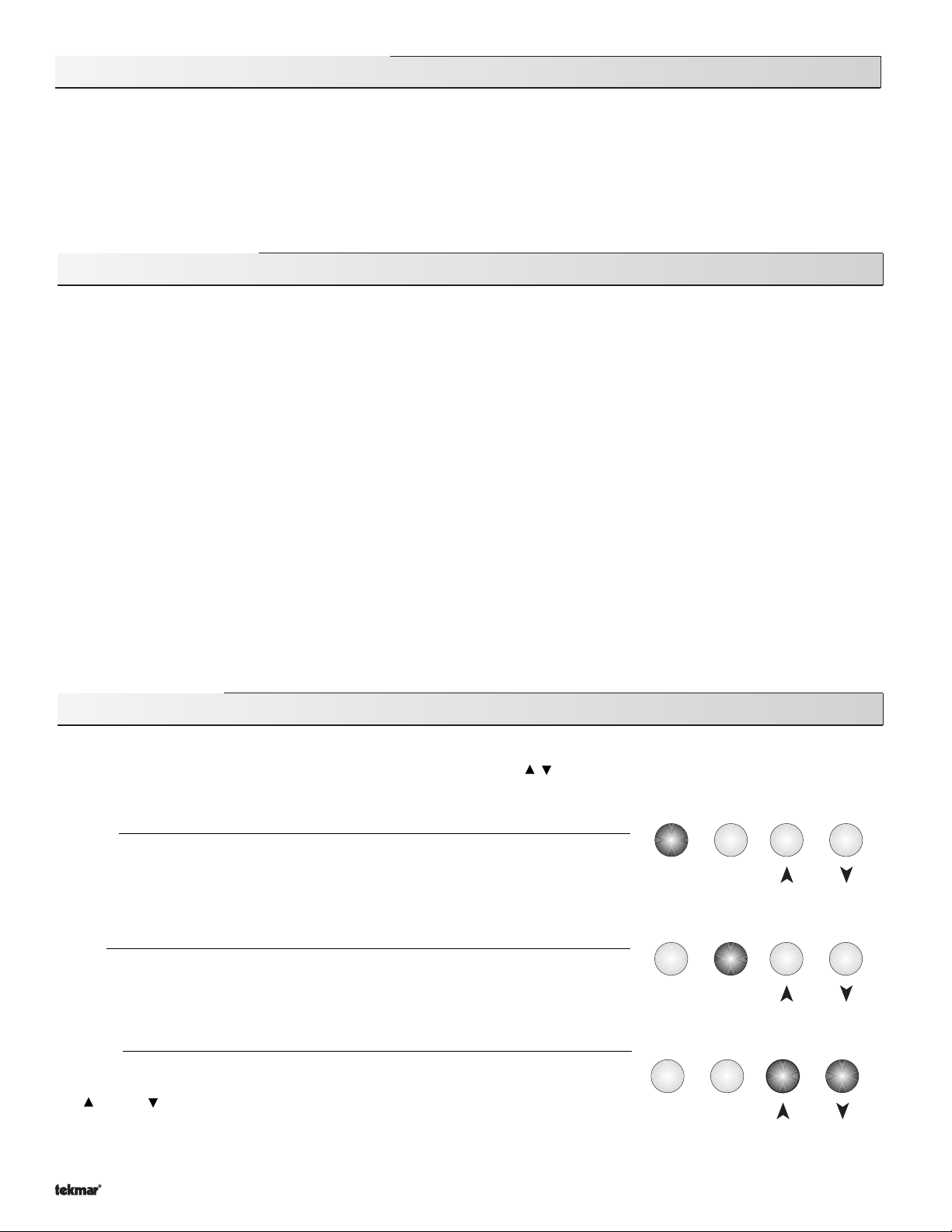
The 362 uses a Liquid Crystal Display (LCD) as the method of supplying information. You use the LCD in order to setup and monitor
the operation of your system. The 362 has four push buttons (Menu, Item, , ) for selecting and adjusting settings. As you program
your control, record your settings in the Adjust Menu table which is found in the second half of this brochure.
Menu
All of the items displayed by the control are organized into various menus. These menus are
listed on the left hand side of the display (Menu Field). To select a menu, use the
button. By pressing and releasing the
available menu. Once a menu is selected, there will be a group of items that can be viewed
within that menu.
Item
The abbreviated name of the selected item will be displayed in the item field of the display.
To view the next available item, press and release the
the last available item in a menu, pressing and releasing the
display to the first item in the selected menu.
Adjust
To make an adjustment to a setting in the control, begin by selecting the appropriate menu
Menu
using the
and / or button to make the adjustment.
button. Then select the desired item using the
Menu
button, the display will advance to the next
Item
button. Once you have reached
Item
button will return the
Item
button. Finally, use the
Menu
Menu
Menu
Menu
Item
Item
Item
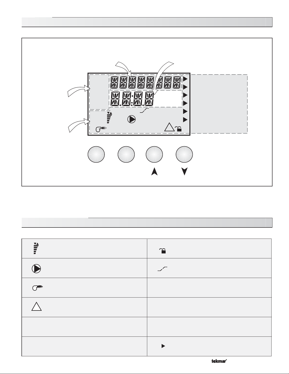
Additional information can be gained by observing the Status and Pointers fields of the LCD. The status field will indicate which of
the control’s outputs are currently active. Most symbols in the status field are only visible when the View Menu is selected.
Copyright © D 362 -12/08
2 of 36
Page 3
Display
Item Field
Displays an abbreviated
name of the selected item
Menu Field
Displays the
current menu
Status Field
Displays the current
status of the control’s
inputs, outputs and
operation
View
Adjust
Monitor
Schd
Misc
Open
Close
Menu
%
1
Item
Aux
1
2
UnOcc
DHW
°F°
sec
Number Field
Displays the current value
of the selected item
Mix Demand
WWSD
C
min
hr
Ovr
Minimum
Maximum
Melting
Idling
!
Buttons
Selects Menus, Items and
{
adjusts settings
Symbol Description
Mixing Device Output Scale
%
1
!
°
F, °C, sec,
min, hr
Open
Close
Shows output of injection pump or mixing valve.
Arrows show whether the output is increasing
or decreasing.
Pump
Displays when mixing pump is in operation.
Burner
Displays when the boiler relay is turned on.
Warning
Displays when an error exists or a specific
limit has been reached.
°F, °C, sec, min, hr
Units of measurement.
Open / Close
Displays when floating actuator is opening or
closing.
Occ
UnOcc
Ovr
Lock - Unlock
Displays whether control is locked or unlocked.
Boost
Displays when control is in morning boost
after setback.
Occupied Schedule
Displays when the control is in occupied mode.
UnOccupied Schedule
Displays when the control is in
unoccupied mode.
Override
Displays when the control is in override mode.
Pointer
Displays the control operation as indicated by
the text.
3 of 36
Copyright © D 362 -12/08
Page 4
P1
OR
Mixing
P1
OR
Mixing
Sequence of Operation
Section A
General
Page 4 - 5
Section B
Mode 1:
Heating
Page 5 - 9
Section C
Mode 2:
Snow Melting
Page 9 - 13
Section D
Boiler Operation
Page 13 - 15
Section A —General Operation
POWERING UP THE CONTROL
When the Mixing Control 362 is powered up, the control displays the control type number in the LCD for 2 seconds. Next, the software
version is displayed for 2 seconds. Finally, the control enters into the normal operating mode and the LCD defaults to displaying the
current outdoor air temperature.
MODES OF OPERATION
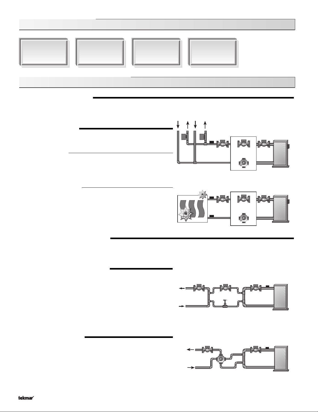
The Mixing Control 362 has two distinct operating modes. The mode of
operation for the control is selected in the Adjust Menu.
MODE 1 (Heating)
Mode 1 is the Heating mode of operation. In this mode, the 362 is an
Outdoor Reset control for a building heating system. The 362 uses a
mixing device to vary the supply water temperature to the building
heating system according to the outdoor conditions.
MODE 2 (Snow Melting)
Mode 2 is the Snow Melting mode of operation. In this mode, the 362 is
a Slab Outdoor Reset control for a single zone of snow melting. The 362
uses a mixing device to vary the supply water temperature to a single
zone snow melting system. In the Snow Melting mode, the 362 uses a
slab sensor and mixing return sensor in order to provide slab temperature
control and slab protection. It is recommended to purchase a Snow Melt
Enable Kit 092 when using this mode of operation.
MIXING DEVICE SELECTION (MIXING)
The 362 can supply a lower water temperature to part of the heating system by varying the speed of an injection pump or modulating
a mixing valve. This selection is made under the MIXING item in the
VARIABLE SPEED INJECTION (VAR)
A standard wet rotor circulator is connected to the 362 on the
Cls / Var
output to the circulator when there is a
varies to maintain the correct mixed supply water temperature at the mix
sensor. For correct sizing and piping of the variable speed injection driven
circulator, refer to essay E 021. A visual indication of the current variable
speed output is displayed in the LCD in the form of a segmented bar graph.
Two small indicators at the top of the graph indicate whether the output is
increasing or decreasing.
FLOATING ACTION (FLOT)
A floating action actuator motor is connected to the 362 on the
Opn
motor open or close to maintain the correct supply water temperature at the
mix sensor when there is a
is connected to can be either a 2-way, 3-way or 4-way valve. A visual
indication as to whether the control is currently opening or closing the
mixing valve is displayed in the LCD with the words Open and Close. Also,
a visual indication of the current position of the valve is displayed in the LCD
in the form of a segmented bar graph.
terminals (8 and 10). The 362 increases or decreases the power
, and
Cls / Var
Copyright © D 362 -12/08
terminals (8, 9 and 10). The 362 pulses the actuator
Mix Demand
Adjust Menu
Pwr Mix
Mix Demand
. The mixing valve that the actuator
. The circulator speed
and
Pwr Mix
4 of 36
.
,
Page 5
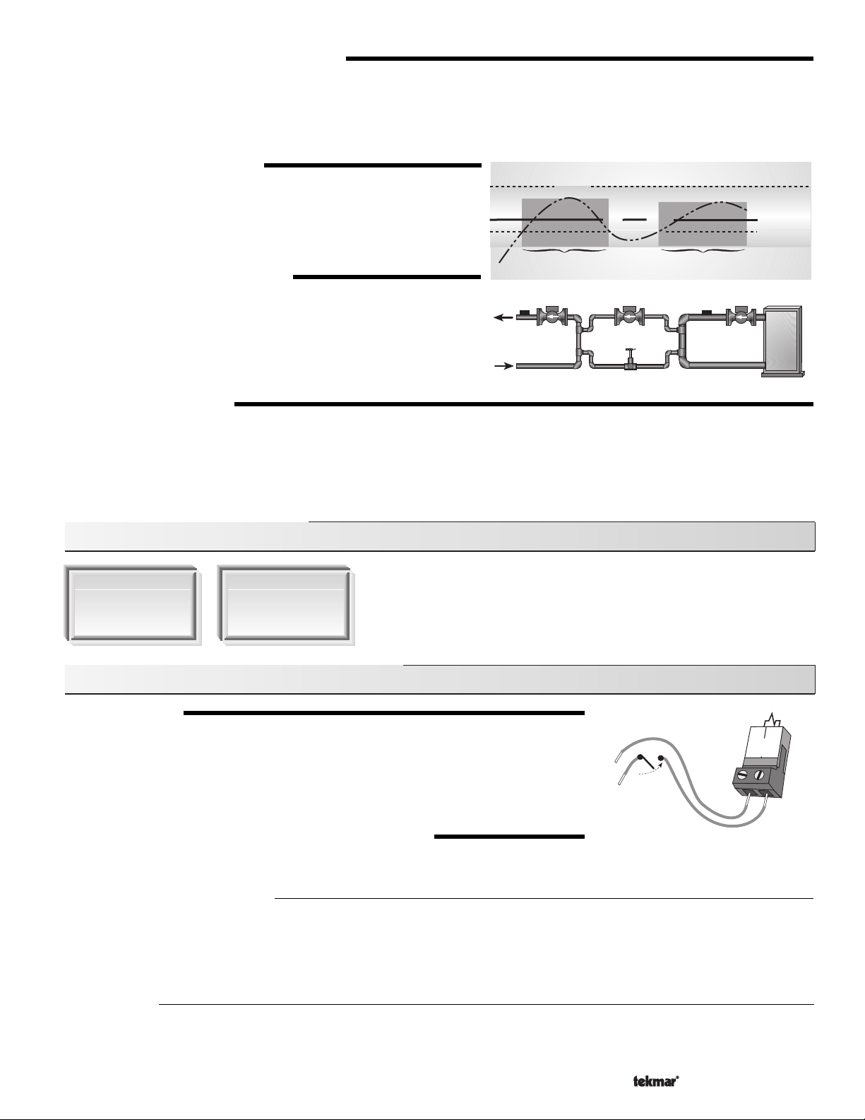
MIXING TARGET TEMPERATURE (MIX TRG)
(
RESET RATIO
When in Mode 1, the MIX TRG temperature is determined from either the
the outdoor air temperature. When in Mode 2, the MIX TRG temperature is determined from either the outdoor air temperature and the
desired slab temperature or the Melting and Idling settings. The control displays the temperature that it is currently trying to maintain
as the mixing supply temperature. If the control does not presently have a requirement for heat, it displays “- - -” in the LCD.
&
CHARACTERIZED HEATING CURVE
)
Characterized Heating Curve
or the
Reset Ratio
settings and
MIXING MAXIMUM (MIX MAX)
The MIX MAX sets the highest water temperature that the control is allowed
to calculate as the MIX TRG temperature. If the control does target the MIX
MAX setting, and the MIX SUP temperature is within 5˚F (3˚C) of the MIX
MAX, the
Maximum
pointer is displayed in the LCD while either the MIX
x
i
e
M
d
S
u
p
p
l
y W
a
t
e
r
T
e
r
u
t
a
r
e
p
m
e
MIX MAX
TRG temperature or the MIX SUP temperature is being viewed.
Pointer On
Pointer On
BOILER PROTECTION (BoiL MIN )
The 362 is capable of providing boiler protection from cold mixing system
return water temperatures. If the boiler sensor temperature is cooler than
the Boil MIN setting while the boiler is firing, the 362 reduces the output
from the mixing device. This limits the amount of cool return water to the
boiler and allows the boiler temperature to recover. This feature can only
be used if the Boil SENS item is not set to NONE.
EXERCISING (EXERCISE)
The 362 has a built-in pump and valve exercising function. The exercising period is adjustable and comes factory set at 70 hours. If a
pump or valve output on the control has not been operated at least once during every exercising period, the control turns on the output
for 10 seconds. This minimizes the possibility of a pump or valve seizing during a long period of inactivity. In the case where a mixing
valve is being used as the mixing device, the 362 ensures that the valve operates over its entire range at least once each exercising
period.
Note: The exercising function does not work if power to the control or pumps is disconnected.
Section B: Mixing Reset (Mode —1—)
Section B1
General Mixing
Operation
Section B2
Alternate Mixing
Demands
Section B1: General Mixing Operation (Mode —1—)
MIXING DEMAND
A mixing demand is generated by applying a voltage between 24 and 240 V (ac) across the
Mix Demand
in the LCD. If the 362 is not in WWSD, the 362 closes the
segment is displayed in the LCD. The 362 calculates a MIX TRG supply temperature based
on the outdoor air temperature and settings. If required, the 362 operates the boiler in order
to provide heat to the mixing device.
CHARACTERIZED HEATING CURVE OR RESET RATIO
When used as a mixing reset control (MODE 1), the 362 has two methods of varying the supply water temperature based on the outdoor
air temperature. The installer can select either a
Characterized Heating Curve
The
Characterized Heating Curve
indoor temperature is the most accurate. The control takes into account the type of terminal unit that the system is using. Since different
types of terminal units transfer heat to a space using different proportions of radiation, convection and conduction, the supply water
temperature must be controlled differently. Once the control is told what type of terminal unit is used, the control varies the supply
water temperature according to the type of terminal unit. This improves the control of the air temperature in the building.
terminals (1 and 2). Once voltage is applied, the
Mix Pmp
Characterized Heating Curve
method of controlling the supply water temperature based on outdoor air temperature and optionally
Mix Demand
pointer is displayed
contact. The Mixing Pump
or a
24 to 240 V (ac)
Reset Ratio
2
1
Mix
Demand
.
Reset Ratio
The
Reset Ratio
method of controlling the supply water temperature is based solely on the outdoor air temperature. This method does
not take into account the type of terminal unit that the heating system is using and therefore is not as accurate as a
Characterized Heating Curve
.
5 of 36
Copyright © D 362 -12/08
Page 6
70
(21)
90
(32)
110
(43)
130
(54)
150
(66)
170
(77)
190
(88)
Outdoor Air Temperature
Supply Water Temperature
210
(99)
-20
(-29)
0
(-18)
20
(-7)
40
(5)
60
(16)
80
(27)
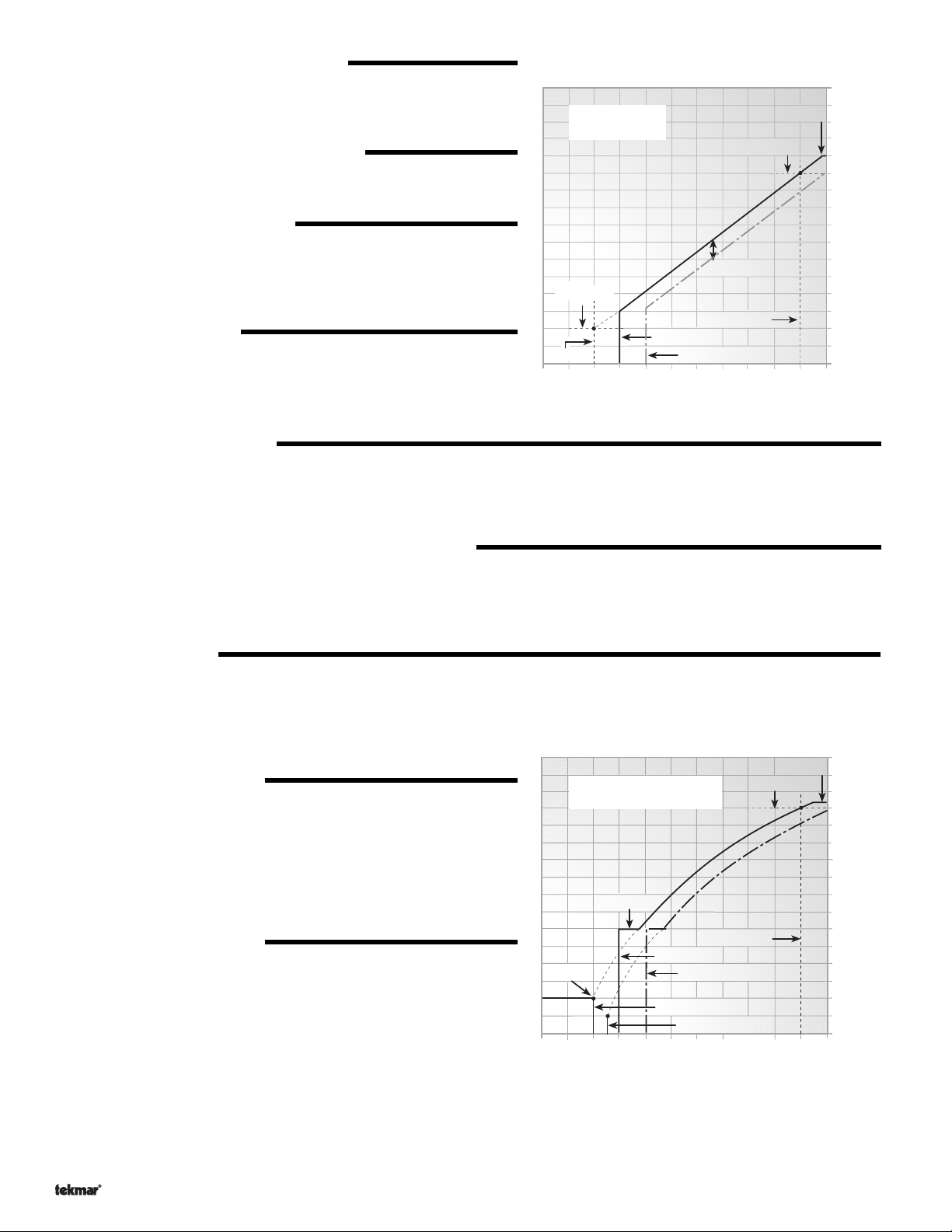
MIX DSGN
MIX MAX
MIX MIN
WWSD Unocc
MIX INDOOR
OUT DSGN
Mixing Characterized
Heating Curve
WWSD Occ
50
(10)
MIX ROOM Occ
MIX ROOM Unocc
MIXING START (MIX STRT)
(
RESET RATIO
)
The MIX STRT temperature is the mixing supply water temperature that the
heating system requires when the outdoor air temperature equals the OUT
STRT air temperature.
OUTDOOR START (OUT STRT)
(
RESET RATIO
)
Mixing Reset
Ratio
MIX MAX
MIX DSGN
The OUT STRT temperature is the outdoor air temperature at which the
control provides the MIX STRT supply water temperature to the system.
OUTDOOR DESIGN (OUT DSGN)
(
RESET RATIO
&
CHARACTERIZED HEATING CURVE
)
The OUT DSGN is the outdoor air temperature that is typically the coldest
o
N
l
a
m
r
MIX SETB
k
c
a
b
t
e
S
temperature of the year where the building is located. This temperature is
used when doing heat loss calculations for the building.
MIX DESIGN (MIX DSGN)
Sequence, Section B
(
RESET RATIO
&
CHARACTERIZED HEATING CURVE
)
The MIX DSGN temperature is the supply water temperature required to
heat the mixing zones when the outdoor air is as cold as the Outdoor Design
temperature.
MIX STRT
OUT STRT
80
(27)
WWSD Occ
WWSD Unocc
60
(16)
40
(5)
Outdoor Air Temperature
OUT DSGN
20
(-7)
0
(-18)
MIXING MAXIMUM (MIX MAX)
(
RESET RATIO
The MIX MAX sets the highest water temperature that the control is allowed to calculate as the MIX TRG temperature. If the control does
target the MIX MAX setting, and the MIX SUP temperature is within 5˚F (3˚C) of the MIX MAX, the
LCD while either the MIX TRG temperature or the MIX SUP temperature is being viewed.
&
CHARACTERIZED HEATING CURVE
)
Maximum
pointer is displayed in the
-20
(-29)
210
(99)
190
(88)
170
(77)
150
(66)
130
(54)
110
(43)
90
(32
70
(21)
Supply Water Temperature
WARM WEATHER SHUT DOWN (WWSD) OCC & UNOCC
(
RESET RATIO
When the outdoor air temperature rises above the WWSD setting, the 362 turns on the
is in Warm Weather Shut Down, the
heating system to satisfy this demand.
SETBACK (SETBACK)
(
RESET RATIO
The SETBACK is the amount that the mixing supply water temperature is reduced when the 362 is placed into an
using an internal or an external setback as described later in this section. This setting is only available if the
selected and
MIXING INDOOR (MIX INDR)
(
CHARACTERIZED HEATING CURVE
The MIX INDR is the room temperature used in the original heat loss
calculations for the building. This setting establishes the beginning of the
Characterized Heating Curve
replaces the MIX STRT water temperature and OUT STRT air temperature
settings used by the
MIXING MINIMUM (MIX MIN)
(
CHARACTERIZED HEATING CURVE
The MIX MIN is the lowest temperature that the control is allowed to use as
a MIX TRG temperature. During mild conditions, if the 362 calculates a
MIX TRG temperature that is below the MIX MIN setting, the MIX TRG
temperature is adjusted to match the MIX MIN setting. During this condition,
the
Minimum
temperature or the MIX SUP temperature is being viewed.
If either an Indoor Sensor or a Room Temperature Unit (RTU) is used and
the 362 is operating at the MIX MIN temperature, the Mixing Pump is cycled using Pulse Width Modulation (PWM) with a 15 minute cycle
length. By cycling the Mixing Pump and controlling the flow of supply water, the control provides an average supply water temperature
to the mixing system. This average temperature is equal to the original MIX TRG. This minimizes overheating of the zone while the control
is operating at the MIX MIN temperature.
Copyright © D 362 -12/08
&
CHARACTERIZED HEATING CURVE
Mix Demand
)
pointer is displayed if there is a demand. However, the control does not operate the
)
Setback / None
DIP switch is set to
Setback
.
)
for the mixing zones. This single setting
Reset Ratio
pointer turns on in the LCD when either the MIX TRG
)
.
6 of 36
WWSD
pointer in the display. When the control
UnOccupied
Reset Ratio
mode,
DIP switch is
Page 7
ROOM OCC & UNOCC (ROOM)
(
CHARACTERIZED HEATING CURVE
The ROOM is the desired room temperature for the mixing zones and it provides a parallel shift of the
The room temperature desired by the occupants is often different from the design indoor temperature (MIX INDR). If the room
temperature is not correct, adjusting the ROOM
Setback / None
DIP switch is set to
)
Characterized Heating Curve
setting increases or decreases the amount of heat available to the building. If the
Setback
, a ROOM setting must be made for both the
Occupied
and
UnOccupied
modes.
.
MIXING TARGET TEMPERATURE (MIX TRG)
(
RESET RATIO
The MIX TRG temperature is determined from either the
temperature. The control displays the temperature that it is currently trying to maintain as the mixing supply temperature. If the control
does not presently have a requirement for heat, it displays “- - -” in the LCD.
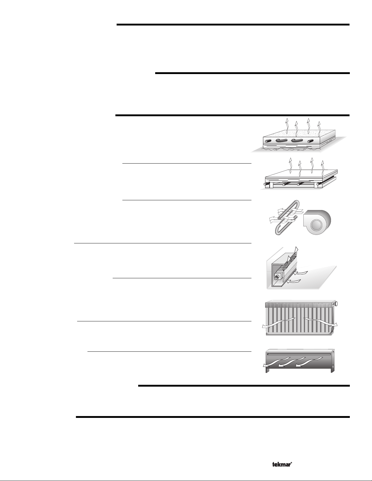
TERMINAL UNITS (TERMINAL)
When using a
unit. The terminal unit determines the shape of the
to how the terminal unit delivers heat into the building space. The 362 provides for selection
between six different terminal unit types: two types of radiant floor heat, fancoil, fin-tube
convector, radiator and baseboard.
Hydronic Radiant Floor
HRF1 is a heavy, or high mass, hydronic radiant floor system. This type of a hydronic radiant
floor is embedded in either a thick concrete or gypsum pour. This heating system has a large
thermal mass and is slow acting.
Hydronic Radiant Floor
HRF2 is a light, or low mass, hydronic radiant floor system. Most commonly, this type of
radiant heating system is either attached to the bottom of a wood sub floor, suspended in
the joist space, or sandwiched between the subfloor and the surface. This type of radiant
system has a relatively low thermal mass and responds faster than a high mass system.
Fancoil
A fancoil terminal unit or air handling unit (AHU) consists of an hydronic heating coil and
either a fan or blower. Air is forced across the coil at a constant velocity by the fan or blower
and is then delivered into the building space.
&
CHARACTERIZED HEATING CURVE
Characterized Heating Curve
(HRF 1)
(HRF 2)
(COIL)
)
Characterized Heating Curve
, the control requires the selection of a terminal
Characterized Heating Curve
or the
according
Reset Ratio
settings and the outdoor air
HRF 1
HRF 2
COIL
Sequence, Section B
Fin–tube Convector
A convector terminal unit is made up of a heating element with fins on it. This type of terminal
unit relies on the natural convection of air across the heating element to deliver heated air
into the space. The amount of natural convection to the space is dependant on the supply
water temperature to the heating element and the room air temperature.
Radiator
A radiator terminal unit has a large heated surface that is exposed to the room. A radiator
provides heat to the room through radiant heat transfer and natural convection.
Baseboard
A baseboard terminal unit is similar to a radiator, but has a low profile and is installed at the
base of the wall. The proportion of heat transferred by radiation from a baseboard is greater
than that from a fin-tube convector.
(RAD)
(BASE)
(CONV)
MIXING PUMP OPERATION (Mix Pmp)
The Mixing Pump contact (
the mixing pump is operated based on the EXERCISE setting in the
PURGE (PURGE)
After the
that the Mixing Pump continues to run is an adjustable time setting. This setting allows any excess heat to be purged out to the heating
system. The Mixing Pump continues to run until the Purging time has elapsed or the mixing supply temperature drops below the MIX
MIN setting. This setting should not be used if the mixing system is zoned using either zone pumps or fast acting zone valves.
Mixing Demand
CONV
RAD
BASE
Mix Pmp
has been satisfied, the 362 can continue to operate the Mixing Pump for a period of time. The length of time
, terminal 5) closes whenever there is a
Adjust
Mixing Demand
Menu.
and the 362 is not in WWSD. During WWSD,
7 of 36
Copyright © D 362 -12/08
Page 8
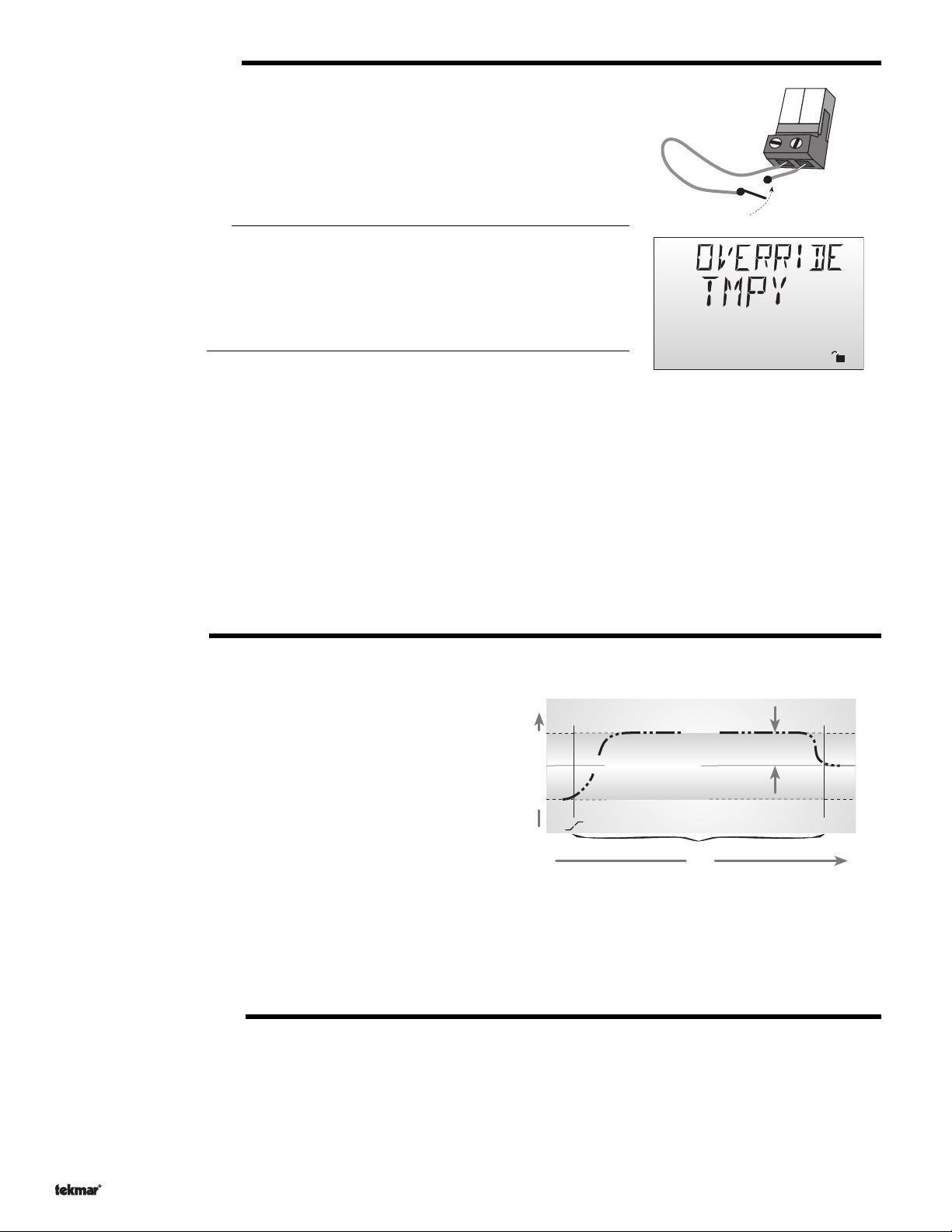
SETBACK (UnOccupied)
To provide greater energy savings, the 362 has a setback capability. With setback, the supply
water temperature in the system is reduced when the building is not used (AWAY) or when
the building is UnOccupied. By reducing the supply water temperature, air temperature in the
space may be reduced even when thermostat(s) are not turned down. This feature is enabled
by setting the
Setback / None DIP
switch to the
Setback
position, and providing either an
external signal or an internal override.
Note: AWAY does not require the DIP switch =
Setback
17
16
UnO
Com
Sw
Timer Switch
External UnOccupied
An external signal can place the 362 into an UnOccupied mode. Any time the
and the
Com
(17) terminals are shorted together, the control operates in the UnOccupied
mode. When in the UnOccupied mode, the
362 adjusts the supply water temperature(s) based on the
the control.
Sequence, Section B
Internal Overrides
The 362 has a number of setback overrides that are selected through the
UnOcc
UnO Sw
segment is displayed in the LCD. The
UnOcc
settings made in
(16)
Schd
UnOcc
Schd
Menu. These
setback overrides have priority over any external setback signal. Any time an override is in
Ovr
effect, the
segment is displayed in the LCD.
Temporary (TMPY)
If a temporary override is selected, the 362 operates in the selected override mode for 3 hours. Once completed, the control reverts
to the previous operation.
Permanent (PERM)
If a permanent override is selected, the 362 operates in the selected override mode until a new override is selected.
Away (AWAY)
If the AWAY override is selected, the 362 operates with a fixed WWSD of 62˚F (17˚C) and a fixed room temperature of 62˚F (17˚C).
BOOSTING (BOOST)
When the control changes from the
enters into a
to the system are raised above their normal values for a period of time to
provide a faster recovery from the building’s setback temperature. The
maximum length of the boost is selected in the user interface. This setting
is only available if a
available for a
Control is used.
Typical settings for the
hours for a building that has a fast responding heating system. For a
building that has a slow responding heating system, a setting between four
hours and eight hours is typical. After a
timer must be adjusted to come out of setback some time in advance of the
desired
BOOST setting. If the building is not up to temperature at the correct time, the BOOST setting should be lengthened and the setback
timer should be adjusted accordingly. If the building is up to temperature before the required time, the BOOST setting should be shortened
and the setback timer should be adjusted accordingly. If the system is operating near its design conditions or if the supply water
temperatures are being limited by settings made in the control, the time required to bring the building up to temperature may be longer
than expected.
Boosting
Occupied
UnOccupied
mode. In this mode, the supply water temperatures
Characterized Heating Curve
Reset Ratio,
and not needed or available if a tekmar Zone
Boost
function vary between 30 minutes and two
Boost
time. This time in advance is normally the same as the
to the
Occupied
mode, it
is selected; It is not
time is selected, the setback
Water Temperature
UnOcc to Occ
Boost
Mix TRG
(Occupied)
Mix
TRG (UnOccupied)
Boost setting - 20 minutes to 8 hours
Time
Self Adjusting
Water Temperature
Ovr
SOFT START (SOF STRT)
The SOF STRT function allows the 362 to slowly ramp the water temperature up to the required supply temperature. By allowing the
temperature in the system to be adjusted slowly, the control reduces any thermal expansion noises and stresses that may be caused
by a quick change in supply water temperature.
Copyright © D 362 -12/08
8 of 36
Page 9
Section B2: Alternate Mixing Demands (Mode —1—)
In addition to using conventional thermostats to provide a mixing demand as described in Section B1, the 362 can use a number of other
methods to provide a mixing demand.
10K INDOOR SENSOR (10K = INDR)
Set the 10K item to INDR to add an indoor sensor for temperature control of a single zone
mixing system. The indoor sensor is connected to the
In addition, power must be applied to the
section B1. With the indoor sensor connected, the 362 is able to sense the actual room
temperature. With this information, the 362 provides a more constant water flow through the
mixing system. At the same time, indoor temperature feedback fine tunes the supply water
temperature in the mixing system to prevent over heating or under heating. To adjust the room
temperature for the mixing zone, use the ROOM
menu at the control.
10K ZONE CONTROL (10K = ZoIn)
Set the 10K item to ZoIn to add indoor temperature feedback control of multiple mixing zones.
Control of mixing zones is provided by connecting a tekmar zone control to the 362. The zone
control provides its own internal
provide an external
Mix Demand
capable of automatically adjusting the MIX TRG temperature to improve building occupant
comfort and system performance.
10K SLAB SENSOR (10K = SLAB)
Set the 10K item to SLAB to add a slab sensor for temperature control of a single zone mixing
system. The 362 can use a slab sensor to control the actual slab temperature. A slab sensor
is placed in the slab and connected to the
be applied to the
Mix Demand
terminals (1 and 2) as described in Section B1. With the slab
sensor connected, the 362 will limit the mixing supply temperature in order to maintain the slab
sensor between the SLAB MIN and SLAB MAX settings.
Slab Minimum
(SLAB MIN)
The SLAB MIN sets the minimum allowed core temperature of the slab as long as the control is not in a WWSD. Caution should be
used when adjusting the SLAB MIN setting as this may lead to overheating of the zone during mild conditions. If the AWAY setting
is selected in the Schedule menu, the 362 ignores the SLAB MIN setting.
Slab Maximum
(SLAB MAX)
The SLAB MAX sets the maximum allowed core temperature of the slab. If the slab is to be maintained at a fixed core temperature,
set SLAB MAX and SLAB MIN items to the same setting.
ROOM TEMPERATURE UNIT (RTU) 062, 063
If the mixing system consists of a single zone, temperature control of that zone can be provided
by using an RTU. The RTU is connected to the
(11 and 13). In addition, power must be applied to the
described in Section B1. With the RTU connected, the 362 measures the actual room
temperature. With this information, the 362 provides a constant water flow through the mixing
system. At the same time, indoor temperature feedback fine tunes the supply water
temperature in the mixing system to prevent over heating or under heating. The RTU allows
the user to adjust the desired room temperature at the RTU. Remote sensor capability is also
available through an RTU as described in the RTU data brochure.
Com
and
10K
terminals (14 and 15).
Mix Demand
Occupied
terminals (1 and 2) as described in
or
UnOccupied
setting in the Adjust
mixing demand
as described earlier in Section B1. The zone control is
to the 362. In this case, there is no need to
Com
and the
10K
terminals (14 and 15). Power must
Com
and tekmar Net
Mix Demand
TM
tN1/tN2
terminals
terminals (1 and 2) as
tekmar
Indoor Sensor
tekmar
Zone Control
Power
Occupied
UnOccupied
Heat Required
Optimum Start / Stop
24 hr. Timer
System Pump
Timer Active
70°F
(21°C)
12 hrs.
Zone 1 Lo stage
1
• Dial the desired duration
618
of the UnOccupied period.
• Press start button at the time of day
Zone 2 Hi stage
2
you want the UnOcc. period to begin.
Timer Active light turns on.
Zone 3 Lo stage
3
0
24
40
100
(4)
(38)
UnOccupied
Zone 4 Hi stage
4
UnOccupied
Duration
Start
0 = always Occupied
24 = always UnOccupied
Zone Control 368
One & Two Stage
tekmar
Slab Sensor
tekmar
RTU
View
°
F
UnOcc 1
ItemMenu
tekmar
362 Control
Mix Demand
View
Boiler Demand
°
F
DHW Demand
Setpoint Demand
Minimum
1
2
%
Maximum
1
DHW
Item
Menu
R
Universal Reset Control 363
NRTL/C
Mixing, Boiler & DHW
LR 58223
LR 58233
E150539
tekmar 362
Control
Mix Demand
View
Boiler Demand
°
F
DHW Demand
Setpoint Demand
Minimum
2
1
%
Maximum
1
DHW
Item
Menu
R
Universal Reset Control 363
NRTL/C
Mixing, Boiler & DHW
LR 58223
LR 58233
E150539
tekmar
362 Control
Mix Demand
View
Boiler Demand
°
F
DHW Demand
Setpoint Demand
Minimum
2
1
%
Maximum
1
DHW
Item
Menu
R
Universal Reset Control 363
NRTL/C
Mixing, Boiler & DHW
LR 58223
LR 58233
E150539
tekmar
362 Control
Mix Demand
View
Boiler Demand
°
F
DHW Demand
Setpoint Demand
Minimum
2
1
%
Maximum
1
DHW
Item
Menu
Heat
Universal Reset Control 363
Mixing, Boiler & DHW
R
NRTL/C
LR 58223
LR 58233
E150539
Section C: Snow Melting (Mode —2—)
Section C1
General Snow
Melting
Section C2
Snow Melting
Enable / Disable
Section C3
With Slab Sensor
Section C4
Without Slab
Sensor
Section C1: General Snow Melting
The Mixing Control 362 is capable of controlling a single zone snow melting system. In order to provide the best control of the snow
melting system, the 362 should be equipped with an optional tekmar Slab Sensor 072 or 073 and an optional Universal Sensor 071 that
measures the slab return temperature. These can be purchased separately or as part of the Snow Melt Enable Kit 092. The Kit also
includes alternate Start / Stop module 039. With these installed, the 362 is capable of providing the features listed in the following section.
Also described in this section are several different methods of starting and stopping the snow melting system.
9 of 36
Copyright © D 362 -12/08
Page 10
NOTE: When operating in the Snow Melting mode, the
operation of the contro
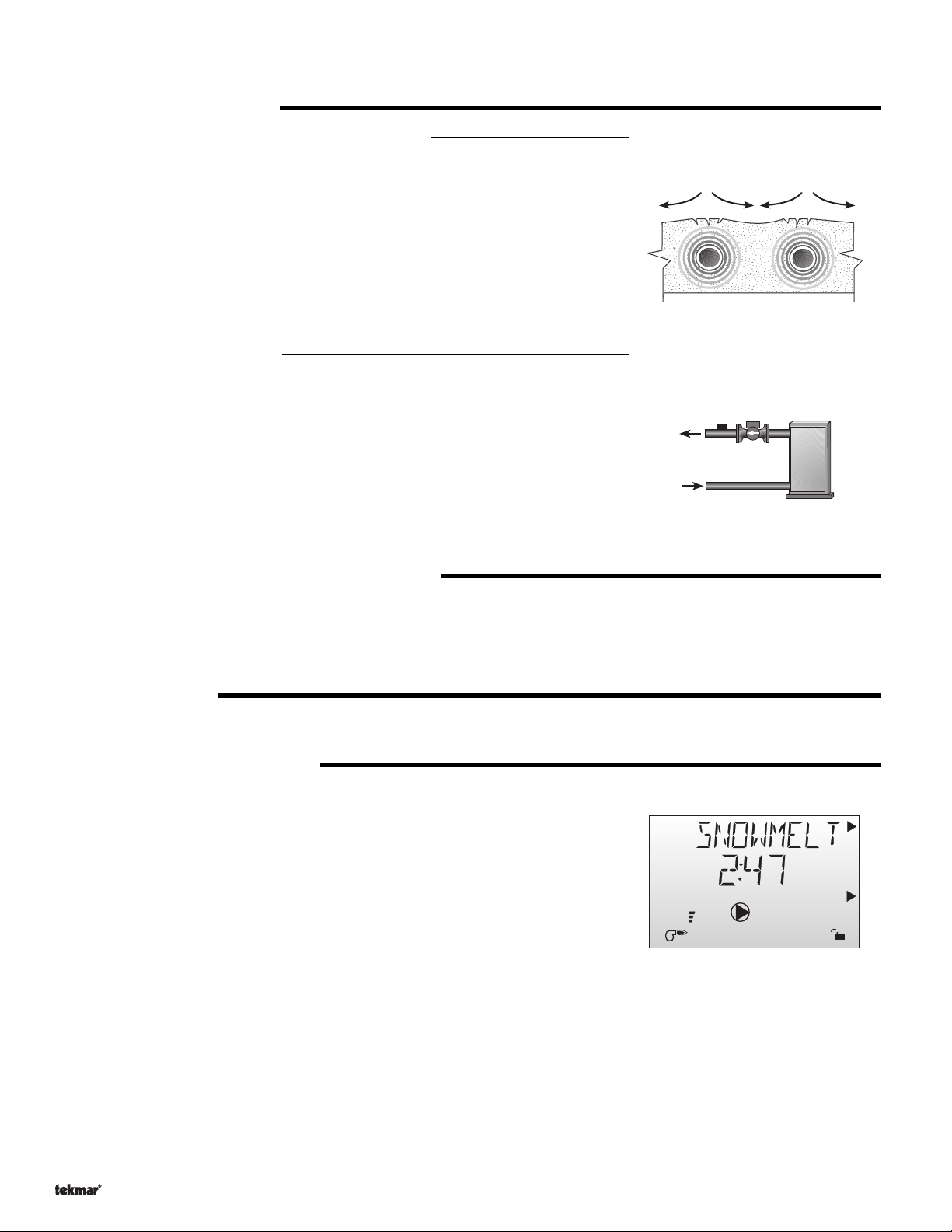
SLAB PROTECTION (∆T MAX)
Boiler Sensor on the Return or No Boiler Sensor
(
NON-DEDICATED HEAT SOURCE
If the snow melting system is one of several loads on a boiler or boiler plant, the amount of
heat available to the system can potentially damage the snow melting slab. The 362 controls
a mixing device that is installed between the snow melting slab and the boiler(s). The control
limits the rate at which heat can be applied to the slab through the
is the temperature difference between the slab supply temperature and the slab return
temperature. By limiting this temperature difference, the rate at which heat is applied to the
slab can be controlled and thermal stresses in the slab can be minimized. When the control
is operating at the ∆T MAX, the
in the View menu. This mode of operation only works when the Boil SENS item is set to RET
or NONE.
Boiler Sensor on the Supply
(
DEDICATED HEAT SOURCE
If the snow melting system consists of a snow melting slab and a dedicated boiler, a mixing
device is installed between the snow melting slab and the boiler to protect the boiler from
low operating temperatures. In a dedicated snow melting system with a properly sized
boiler, it is not necessary for the control to provide ∆T protection of the snow melting slab;
Since the boiler output is matched to the slab requirements, it is not possible to heat the slab
too rapidly and cause thermal stresses that will result in damage to the slab. Therefore, the
∆T MAX item in the
When operating a dedicated snow melting system, the 362 is designed to operate the boiler
as efficiently as possible. This mode of operation only works when the Boil SENS item is
set to SUP.
Adjust
)
Maximum
pointer can be seen when viewing the MIX ∆T item
)
menu and the MIX ∆T item in the
Reset Ratio / Characterized Heating Curve DIP switch
∆T MAX setting. The ∆T
View
menu are not available.
has no effect on the
tensile stress
VISCOSITY COMPENSATION (EXCEEDING ∆T MAX)
At low temperatures, the glycol solutions used in snow melting systems become very viscous and difficult to pump. In order to overcome
this condition during a cold start of a snow melting system, the 362 is allowed to exceed the ∆T MAX setting for a period of time in order
to warm the glycol solution. This allows the control to compensate for the high viscosity of the glycol solution and is used when the supply
temperature is below 30˚F (-1˚C). When the control exceeds the
item in the
RAMPING OF THE ∆T
When the control starts applying heat to the slab, the supply temperature to the snow melting system is ramped up over a period of time
until it reaches the maximum allowed ∆T. This function does not occur when the boiler sensor is on the supply.
OPERATING STATUS (SNOWMELT)
While in the Snow Melting mode (Mode 2), an additional item is available in the
current operating status of the snow melting system.
• STRT The word STRT is displayed after the snow melting system has been enabled. It is
• STOP The word STOP is displayed for five seconds after the snow melting system has
• IDLE The word IDLE is displayed as long as the control is operating the slab at the idling temperature.
• EXT The word EXT is displayed when the RUN TIME has reached 0:00 and the control still has an external demand for melting. In
• 0:00 to 17:00 hr While the slab is up to temperature, and the control is melting, the remaining RUN TIME is displayed.
• INF If an infinite RUN TIME is selected and the control is melting, INF is displayed.
• WWSD When the control is in a Warm Weather Shut Down, WWSD is displayed.
• CWCO When the control is in a Cold Weather Cut Off, CWCO is displayed
View
menu.
displayed until the slab reaches the melting temperature. If the slab is at the melting
temperature, STRT is displayed for five seconds after the snow melting system has
started operation. This is to verify that the control has entered into the
snow melting mode.
stopped operation. The word STOP is also displayed if either a Remote Start/Stop
Module 039 or Remote Display Module 040 stops the snow melting system and an
external demand is still present.
this situation, the control continues melting until the snow melting demand is removed or the control is stopped.
∆T MAX setting, the
Maximum
View
menu called SNOWMELT. This item displays the
pointer will flash when viewing the MIX ∆T
View
%
1
hr
Copyright © D 362 -12/08
10 of 36
Page 11
RUNNING TIME (RUN TIME)
The running time is the length of time that the snow melting system operates once the slab has reached the melting temperature. During
the time that the slab is approaching the melting temperature, the RUN TIME does not decrease. Once the slab has reached the melting
temperature, the RUN TIME begins counting down. When the RUN TIME reaches 0:00 as displayed by the SNOWMELT item in the
menu, the 362 has finished Melting.
View
WARM WEATHER SHUT DOWN (WWSD)
When both the slab temperature and the outdoor temperature exceed the
Melting temperature by more than 1.5˚F (1˚C), the control enters into a
WWSD. In a WWSD, the snow melting system is shut down in order to
conserve energy.
COLD WEATHER CUT OUT (CWCO)
Maintaining the slab at either the Melting or Idling temperature during extremely cold temperatures can be expensive or impossible. The
control shuts off the snow melting system once the outdoor air temperature drops below the Cold Weather Cut Out (CWCO) temperature.
While the control is in a CWCO, the word CWCO is displayed in the SNOWMELT item in the View menu. If the control had been started
prior to the CWCO, it resumes the melting mode once the outdoor air temperature rises above the CWCO temperature.
BOILER OPERATION
Refer to section D for a description of the boiler operation.
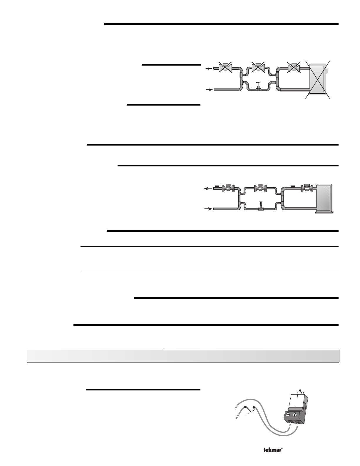
BOILER PROTECTION (Boil MIN)
The 362 ensures that the boiler supply water temperature remains above
the Boil MIN setting. If the boiler supply water temperature begins to drop
due to the slab return temperature, the mixing device is throttled back to
allow the boiler to recover. This minimizes the time that the boiler operates
below its condensing temperature and prolongs the life of the boiler. The
362 can only provide boiler protection if the Boil SENS item is set to SUP
or RET. The 362 cannot provide boiler protection if the Boil SENS item is
set to NONE.
SNOW MELTING OVERRIDE
Sequence, Section C2
Internal Override
If the AWAY setting is selected in the Schedule menu, the system is shut down. Both the
as long as the control remains in the AWAY mode. The
External Override
While in Mode 2, any signal received on the UnO Sw and COM terminal (16 and 17) is ignored and does not affect the operation of
the control.
MIXING PUMP OPERATION (Mix Pmp)
The Mixing Pump (Mix Pmp) contact closes and remains closed as long as the control is either in the Melting or Idling mode. The Mixing
Pump contact shuts off if the control is in WWSD, CWCO, or if there is no call for Melting or Idling.
PURGE (PURGE)
The Mixing Pump (Mix Pmp) continues to operate for the set PURGE time after the control finishes operation.
Melting
and
Idling
temperatures are ignored
Setback / N one
DIP does not matter for internal overrides.
Section C2: Snow Melting Enable (Mode —2—)
There are three methods in which the snow melting system can be enabled on the Mixing Control 362. Either an
Remote Start / Stop Module 039
EXTERNAL DEMAND
An external snow melting demand is generated when a voltage between
24 and 240 V (ac) is applied across
external demand must be present for at least 4 seconds in order to start the
snow melting system. Once started, the slab temperature is increased to
the MELTING setting and maintained at the melting temperature until the
Run Time reaches 0:00. If the Run Time reaches 0:00 and the external
demand is still present, the control continues at the melting temperature
until the external demand is removed or the system is otherwise stopped.
or a
Remote Display Module 040
Mix Demand
(1 and 2) terminals. An
can be used to start the snow melting system.
24 to 240 V (ac)
11 of 36
External Demand
2
1
Mix
Demand
Copyright © D 362 -12/08
, a
Page 12
REMOTE START / STOP MODULE 039
A Remote Start / Stop Module 039 can be used to start and stop the snow melting system and
adjust the running time. Refer to data brochure D 039 for details of operation.
REMOTE DISPLAY MODULE 040
A Remote Display Module 040 can be used to start and stop the snow melting system. The
snow melting system is enabled by pressing the Up button on the 040 while in the View menu.
Once the snow melting system is enabled, the word STRT is displayed in the LCD for at least
five seconds. The 040 then displays the Run Time setting to allow the user to adjust it.
To disable the snow melting system when it is in the melting mode, press the Down button on
the 040 while in the View menu. The word STOP is displayed for five seconds.
Section C3: With Slab Sensor (Mode —2—)
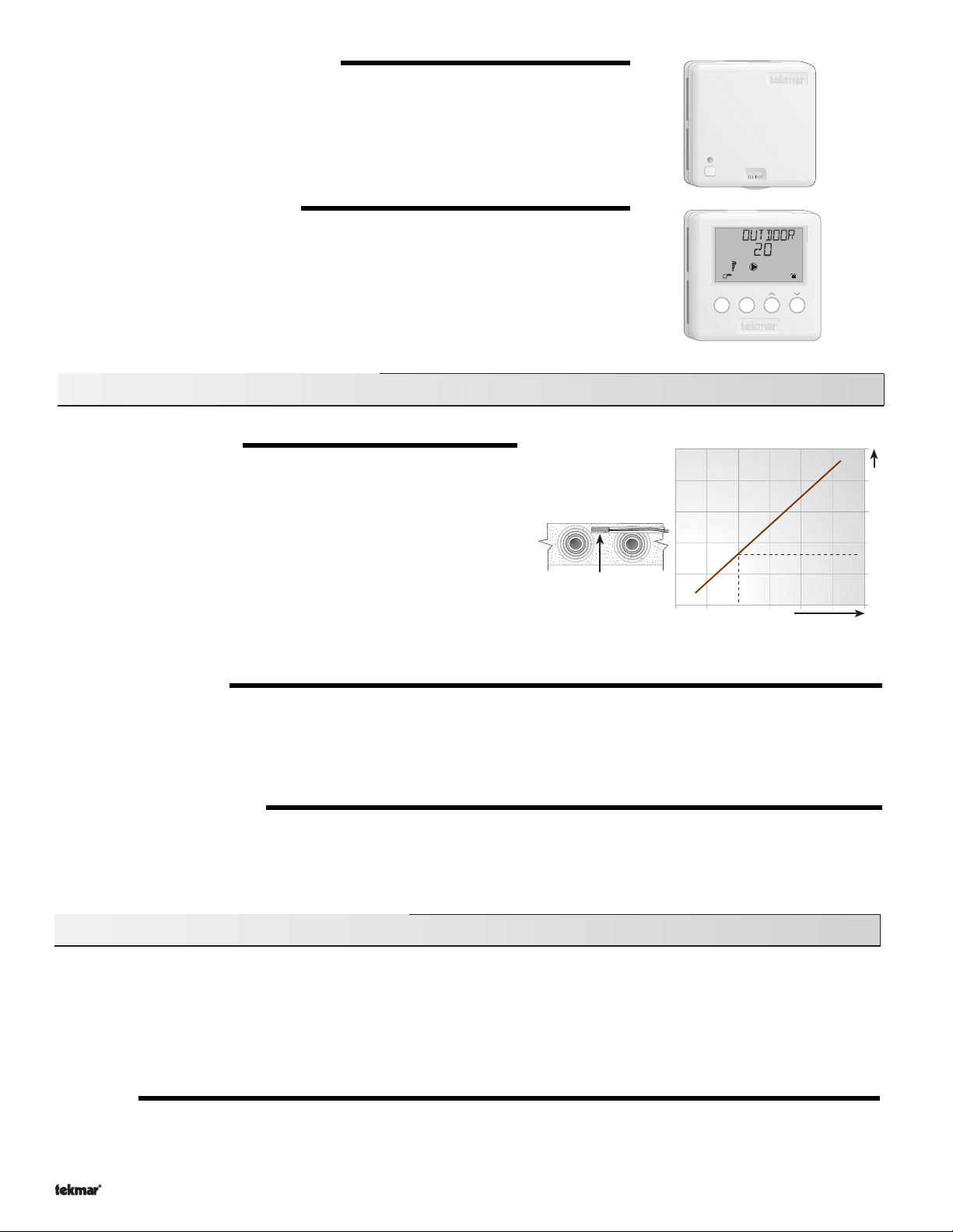
SLAB OUTDOOR RESET
A slab sensor maybe installed to provide more accurate temperature
control. The control assumes that the sensor is approximately 1 inch below
the surface of the snow melting slab. Since this point is closer to the source
of the heat, this point is warmer than the surface of the slab. Therefore, the
sensor must be maintained at a higher temperature in order to ensure that
the surface of the slab is maintained at the correct temperature. The
amount of temperature difference between the surface of the slab and the
slab sensor changes with the outdoor air temperature. Therefore, the slab
core temperature is increased as the outdoor air temperature drops. The
temperature displayed as the slab temperature is the temperature of the
slab sensor. This sensor temperature is higher than the surface temperature of the slab.
surface
temperature = 35°F
core (sensor) is warmer
79
8
View
Open
Decreasing Air Temperature
°F°
h
1
2
%
1
DH
ItemMenu
Constant slab surface temperature
Increasing Slab Core Temperature
IDLING MODE (IDLING)
When the snow melting system starts from a cold temperature, the time required for the slab to reach the “Melting” temperature may
be excessive. To decrease this start up time, the slab can be maintained at an “Idling” temperature. The idle feature is also useful for
preventing frost and light ice formation. When the control is in idling mode, the
pointer is visible in the View menu and the word
Idling
IDLEcan be read when looking at the SNOWMELTitem in the View menu. The IDLING setting in the Adjust menu sets the slab surface
temperature that is maintained while the control is in the idling mode.
MELTING MODE (MELTING)
The Mixing Control 362 is a manual snow melting control. In order for the snow melting system to be started, one of the three methods
described in section C2 must be used. When the control is in the melting mode, the
Melting
pointer is visible in the View Menu and either
EXT, INF or a running time can be read when viewing the SNOWMELTitem in the View menu.The MELTING setting in the Adjust Menu
sets the slab surface temperature that is maintained while the control is in the melting mode.
Section C4: Without Slab Sensor
mode.
In cases where a slab sensor has not been or cannot be installed in the snow melting slab, it is possible for the Mixing Control 362
to operate the snow melting system. This mode of operation is not recommended since the control can no longer regulate the
slab temperature. This method of operation can cause the slab to operate at surface temperatures that are higher than required. A
higher surface temperature can lead to excessive energy usage and fuel costs. The sequence of operation for the control when it is
operating without a slab sensor is the same as described in sections C1 and C2.
However, the following items change as described:
RUN TIME
As there is no slab sensor, the RUN TIME clock does not wait for the slab to reach MELTING temperature to start counting down,
but instead starts counting down as soon as the control starts the melting operation.
Copyright © D 362 -12/08
12 of 36
Page 13
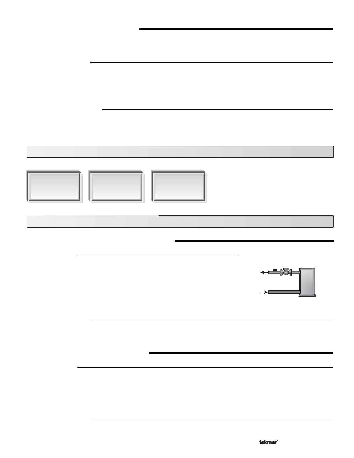
WARM WEATHER SHUT DOWN (WWSD)
Since a slab sensor is not in use, the Warm Weather Shut Down is determined only from the outdoor air temperature. Once the outdoor
air temperature rises above the WWSD setting, the control goes into a WWSD and ignores any demand for Idling or Melting. Also the
word WWSD is displayed when viewing the SNOWMELT item in the View Menu.
IDLING MODE (IDLING)
When the snow melting system starts from a cold temperature, the time required for the slab to reach the Melting temperature may be
excessive. To decrease this start up time, the slab can be maintained at an Idling temperature. The Idle feature is also useful for
preventing frost and light ice formation. When the control is in idling mode, the Idling pointer is visible in the View menu and the word
IDLE can be read when looking at the SNOWMELT item in the View menu. The IDLING setting in the Adjust menu sets the desired slab
sensor temperature.
MELTING MODE (MELTING)
The Mixing Control 362 is a manual snow melting control. In order for the snow melting system to be started, one of the three methods
described in Section C2 must be used. When the control is in the melting mode, the Melting pointer is displayed in the View Menu and
either EXT, INFor a running time can be read when viewing the SNOWMELTitem in the View menu. The MELTING setting in the Adjust
menu sets the desired slab surface temperature.
Section D: Boiler Operation (Mode —1— and —2— )
Section D1
Boiler Supply
Sensor
Section D2
Boiler Return
Sensor
Section D3
No Boiler Sensor
Section D1: Boiler Supply Sensor
BOILER SENSOR ON THE SUPPLY (Boil SENS = SUP)
Mode 1: Heating
The boiler sensor can be located on the boiler supply if the 362 is the only control that is
operating the boiler. When in the supply mode, the 362 determines the required operating
temperature for the boiler supply and cycles the
correct boiler supply water temperature. If this mode of operation is selected, the boiler
pump should either operate continuously or be operated in parallel with the Mixing Pump
contact (Mix Pmp). The boiler pump should not be operated by the operating aquastat as
this may lead to improper cycling of the boiler because of inconsistent flow past the boiler
supply sensor. This mode of operation only works if the Boil SENS item is set to SUP.
Mode 2: Snow Melting
When operating a boiler that is dedicated to a snow melting system, the 362 is designed to operate the boiler as efficiently as possible.
The boiler is cycled based on the mixing supply water temperature. This is to provide longer and more efficient boiler cycles. This mode
of operation only works if the Boil SENS item is set to SUP.
contact in order to maintain the
Boiler
BOILER TARGET TEMPERATURE (Boil TRG)
Mode 1: Heating
When operating in Mode 1, the Boiler Target temperature is determined by the operation of the mixing device. The Mixing Control
362 uses a method called
the boiler at a supply temperature that is sufficient to satisfy the requirements of the mixing device. If the boiler supply water
temperature is not sufficient, the 362 increases the boiler target temperature. If the boiler supply water temperature is more than
sufficient, the 362 decreases the boiler target temperature. If the control does not have a requirement for heat from the boiler, it does
not show a boiler target temperature. Instead, - - - is displayed in the LCD.
Boiler Load Reset
in order to determine the required boiler supply water temperature. The 362 operates
Mode 2: Snow Melting
When operating in Mode 2, the boiler target temperature is determined by the mixing target temperature. The mixing target
temperature is automatically determined by the control.
13 of 36
Copyright © D 362 -12/08
Page 14
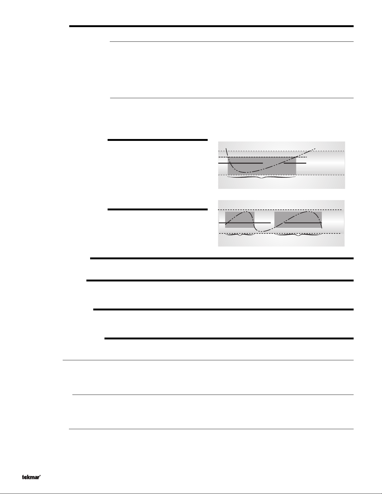
Pointer On
Boil MIN
B
o
i
l
W
a
t
e
r
T
e
m
p
er
a
t
u
r
e
Boil Min + 1/2 Boiler Differential
Boil Min - 1/2 Boiler Differential
DIFFERENTIAL
Mode 1: Heating
(Boil DIFF)
When operating in Mode 1, an on / off heat source such as a boiler must be operated with a differential to prevent short cycling. This
differential is centered around the Boil TRG temperature. If the boiler supply temperature drops 1/2 of the differential below the
Boil TRG temperature, the 362 closes the boiler contact to fire the boiler. If the boiler supply temperature rises 1/2 of the differential
above the Boil TRG temperature, the 362 opens the boiler contact to turn off the boiler. With the 362, either a fixed or automatic
differential setting is selected. If the AUTO differential is selected, the 362 automatically adjusts the boiler differential setting under
the current load conditions to avoid short cycling.
Mode 2: Snow Melting
(DIFF)
When operating in Mode 2 with the boiler sensor on the boiler supply, it is necessary to set a differential for the boiler. This differential
is centered around the MIX TRG temperature. If the mixing supply temperature drops 1/2 of the differential below the MIX TRG
temperature, the 362 closes the boiler contact to fire the boiler. If the mixing supply temperature rises 1/2 of the differential above the
MIX TRG temperature, the 362 opens the boiler contact to turn off the boiler.
Sequence, Section D1
BOILER MINIMUM (Boil MIN)
The Boil MIN is the lowest water temperature that the control is allowed to
use as a Boil TRG temperature. During mild conditions, if the 362 calculates
a Boil TRG temperature that is below the Boil MIN setting, the Boil TRG
temperature is adjusted to at least the Boil MIN setting. During this
condition, if the boiler is operating, the
Minimum
pointer turns on in the LCD
while the Boil TRG or the Boil SUP temperature is viewed. If the installed
boiler is designed for condensing operation, set the Boil MIN adjustment
to OFF.
BOILER MAXIMUM (Boil MAX)
The Boil MAX is the highest water temperature that the control is allowed
to use as a Boil TRG temperature. If the control does target Boil MAX, and
the Boil SUP temperature is near the Boil MAX temperature, the
pointer turns on in the LCD while the Boil TRG or the Boil SUP temperature
is viewed. At no time does the control operate the boiler above 248˚F (120˚C).
Maximum
Pointer On
Boil Max + 1/2 Boiler Differential
e
r
u
t
a
r
e
p
m
e
T
r
e
t
a
W
l
i
B
o
Boil Max - 1/2 Boiler Differential
Pointer On
Boil MAX
BOILER PROTECTION
Refer to section A for a description of boiler protection.
BOILER OPERATION
When the 362 determines that boiler operation is required, the
Boiler
contact terminals (6 and 7) close. While the boiler contact is closed,
the burner segment in the LCD is displayed.
FIRE DELAY (FIRE DLY)
The FIRE DLY is the delay time that may happen between the time that the 362 closes the boiler contact and the burner fires. This delay
is usually the result of a burner pre-purge or other forms of time delay built into the burner’s safety circuits.
BOILER MASS (Boil MASS)
The Boil MASS setting allows the 362 to adjust to different types of heat sources depending on their thermal mass.
(LITE)
Light
The LITE setting is selected if the boiler that is being used has a low thermal mass. This means that the boiler has a very small water
content and has very little metal in the heat exchanger. A boiler that has a low thermal mass comes up to temperature quite rapidly.
This is typical of many copper fin-tube boilers.
Medium
(MED)
The MED setting is selected if the boiler that is being used has a medium thermal mass. This means that the boiler either has a large
water content and a low metal content or a low water content and a high metal content. This is typical of many modern residential
cast iron boilers.
Heavy
(HEVY)
The HEVY setting is selected if the boiler that is being used has a high thermal mass. This means that the boiler has both a large water
content and a large metal content. A boiler that has a high thermal mass is relatively slow in coming up to temperature. This is typical
of many commercial cast iron and steel tube boilers.
Copyright © D 362 -12/08
14 of 36
Page 15
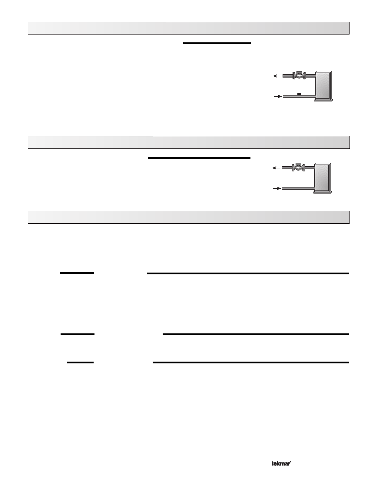
Section D2: Boiler Return Sensor
BOILER SENSOR ON THE RETURN (Boil SENS = RET)
The boiler sensor should be located on the boiler return if the 362 is one of many controls that
can call for boiler operation. When in the return mode, the 362 provides a boiler enable. The
362 no longer tries to control the boiler supply water temperature directly but allows the boiler
to operate at its operating aquastat setting. If this mode of operation is selected, the boiler
pump should either operate continuously or be operated in parallel with the Mixing Pump. The
boiler pump should not be operated by the boilers aquastat as this may lead to improper
cycling of the boiler because of inconsistent flow past the boiler return sensor.
When the mixing device begins to ramp up, the boiler contact on the 362 closes. The boiler
contact remains closed until the mixing device no longer requires heat. With the sensor on the
boiler return, the 362 is still capable of providing boiler return protection as described in
section A.
Section D3: No Boiler Sensor
NO BOILER SENSOR (Boil SENS = NONE)
The 362 is capable of operating without a boiler sensor if desired. Without a boiler sensor, the
362 is unable to provide boiler return protection. The boiler contact still functions without the
boiler sensor. When the mixing device begins to ramp up, the boiler contact on the 362 closes.
The boiler contact remains closed until the mixing device no longer requires heat. This type
of application is typical if the 362 is drawing heat from a heat source that already incorporates
some form of boiler return protection.
Installation
CAUTION
Improper installation and operation of this control could result in damage to the equipment and possibly even personal injury. It is your
responsibility to ensure that this control is safely installed according to all applicable codes and standards. This electronic control is
not intended for use as a primary limit control. Other controls that are intended and certified as safety limits must be placed into the
control circuit.
STEP ONE
Check the contents of this package. If any of the contents listed are missing or damaged, please contact your wholesaler or tekmar sales
representative for assistance.
Type 362 includes
Note
STEP TWO
Remove the control from its base by pressing down on the release clip in the wiring chamber and sliding the control upwards. The base
is then mounted in accordance with the instructions in the Data Brochure D 001.
STEP THREE
All electrical wiring terminates in the control base wiring chamber. The base has standard 7/8” (22mm) knockouts which accept common
wiring hardware and conduit fittings. Before removing the knockouts, check the wiring diagram and select those sections of the chamber
with common voltages. Do not allow the wiring to cross between sections as the wires will interfere with safety dividers which should
be installed at a later time.
: Carefully read the details of the Sequence of Operation to ensure that you have chosen the proper control for your application.
GETTING READY
: One Mixing Control 362, One Outdoor Sensor 070, Two Universal Sensors 071, Data Brochures D 362,
D 070, D 001, User Brochure U 362, Application Brochures A 362, Essays E 003, E 021.
MOUNTING THE BASE
ROUGH-IN WIRING
Power must not be applied to any of the wires during the rough-in wiring stage.
• Install the Outdoor Sensor 070, Boiler Sensor 071, and Mixing Sensor 071 according to the instructions in the Data Brochure D070
and run the wiring back to the control.
• If a Room Temperature Unit (RTU) 062 or 063 is used, install the RTU according to the installation instructions in the Data Brochure
D 062 and run the wiring back to the control.
15 of 36
Copyright © D 362 -12/08
Page 16
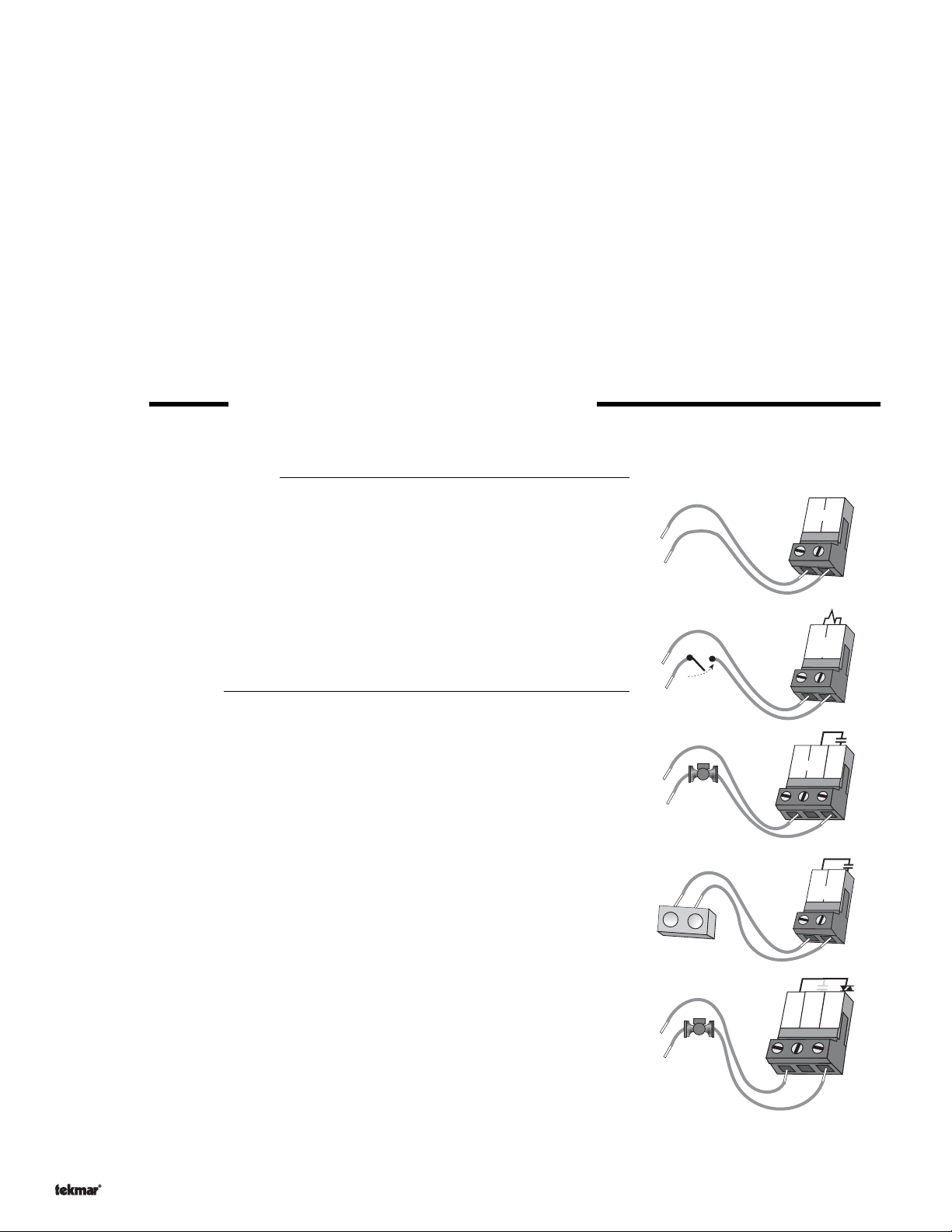
• If a Slab Sensor 072 or 073 is used, install the Slab Sensor according to the installation instructions in the Data Brochure D 070
and run the wiring back to the control or RTU.
• If a Remote Display Module (RDM) 040 is used, install the RDM according to the installation instructions in the Data Brochure D 040
and run the wiring back to the control.
• If a Remote Start / Stop Module 039 is used, install the module according to the installation instructions in the Data Brochure D 039
2E noitceS ,ecneuqeS
and run the wiring back to the control.
• If a tekmar Zone Control is used, run the wires from the Zone Control to the 362. Refer to the instructions supplied with the Zone
Control.
• Run wire from other system components (pumps, boiler, actuator motors, etc.) to the control.
• Run wires from the 120 V (ac) power to the control. Use a clean power source to ensure proper operation. Multi-strand 16 AWG
wire is recommended for all 120 V (ac) wiring due to its superior flexibility and ease of installation into the terminals.
• 120 V (ac) to be provided from a 15 A circuit breaker and must have a circuit disconnect installed.
• Connect ground wires to ground bus bar in wiring area.
STEP FOUR ELECTRICAL CONNECTIONS TO THE CONTROL
The installer should test to confirm that no voltage is present at any of the wires. Push the control into the base and slide it down until
it snaps firmly into place.
Powered Input Connections
120 V (ac) Power
Connect the 120 V (ac) power supply to the
Power N
This connection provides power to the microprocessor and display of the control. As
well, this connection provides power to the
Mix Pmp
terminal (4).
Power L
and
terminals (3 and 4).
terminal (5) from the
Power L
120 V (ac)
3
Power
N
4
L
Mixing Demand
To generate a Mixing Demand, a voltage between 24 V (ac) and 240 V (ac) must be
applied across the
Mix Demand
terminals (1 and 2).
Output Connections
Mixing Pump Contact (Mix Pmp)
The
Mix Pmp
362 closes, 120 V (ac) is provided to the
output terminal (5) on the 362 is a powered output. When the relay in the
Mix Pmp
terminal (5) from the
Power L
(4). To operate the mixing pump, connect one side of the mixing pump circuit to terminal
5 and the second side of the pump circuit to the neutral (N) side of the 120 V (ac)
power supply.
Boiler Contact
The boiler terminals (6 and 7) are an isolated output in the 362. There is no power
available on these terminals from the control. These terminals are to be used as a
switch to either make or break the boiler circuit. When the 362 requires the boiler to fire,
it closes the contact between terminals 6 and 7.
Variable Speed Injection Pump
The 362 can vary the speed of a permanent capacitor, impedance protected or
equivalent pump motor that has a locked rotor current of less than 2.4 A. Most small
wet rotor circulators are suitable as described in Essay E 021. The 362 has an internal
overload protection fuse which is rated at 2.5 A 250 V (ac). Contact your tekmar sales
representative for details on the repair procedures if this fuse is blown.
Connect one of the wires from the variable speed injection pump to the
terminal (10) on the 362. Connect the
V (ac) power source. The other wire on the variable speed injection pump must be
connected to the neutral (N) side of the 120 V (ac) power supply.
Pwr Mix
terminal (8) to the live (L) side of the 120
terminal
Cls / Var
24 to 240 V (ac)
L
N
120 V (ac)
T
T
T
T
L
N
120 V (ac)
Pwr
Mix
3
Power
N
8
1
Mix
Demand
4
L
6
Boiler
9
Opn
Mix
Pmp
10
Cls/
Var
2
5
7
Copyright © D 362 -12/08
16 of 36
Page 17
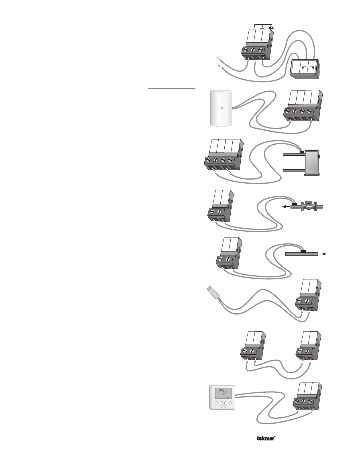
8
9
Pwr
Mix
Opn
Cls /
Var
10
24 or 120 V (ac)
Com
C
R
17
18
Com
Mix
Boil
19
20
Out
17
18
Com
Mix
Boil
19
20
Out
Boiler
sensor
11
12
Com
Mix
Ret
tN1/
tN2
13
ItemMenu
UnOcc 1
°
F
View
Heat
11
12
Com
Mix
Ret
Mixing
Return
Sensor
Mixing Valve Actuator
Connect one side of the 24 V (ac) power to the
Opn
on the control. The output relay
(9) is then connected to the
open terminal of the actuating motor and the output relay
(10) is connected to the close terminal of the actuating motor.
Connect the second side of the 24 V (ac) circuit to the common
terminal of the actuating motor.
Pwr Mix
terminal (8)
Cls / Var
Sensor and Unpowered Input Connections
Do not apply power to these terminals as this will damage the
control.
Outdoor Sensor
Connect the two wires from the Outdoor Sensor 070 to the
Out
terminals (17 and 20). The Outdoor Sensor is used by the 362
to measure the outdoor air temperature.
Com
Boiler Sensor
Connect the two wires from the Boiler Sensor 071 to the
Boil
terminals (17 and 19). The Boiler Sensor is used by the 362 to
measure the supply (outlet) water temperature from the boiler.
Com
Mixing Sensor
Connect the two wires from the Mixing Sensor 071 to the
Mix
terminals (17 and 18). The Mixing Sensor is used by the 362 to
measure the supply water temperature after the mixing device.
Normally the sensor is attached to the pipe downstream of the
mixing pump.
Com
Mixing Return Sensor
Connect the two wires from the Mixing Return Sensor 071 to the
Com
and
Mix
terminals (11 and 12). The Mixing Return Sensor is
used by the 362 to measure the fluid return temperature from the
snow melting slab.
and
and
and
17
Com
18
Mix
Mixing
sensor
10K Sensor
Either an Indoor Sensor, Slab Sensor, or Zone Control can be
connected to the
wires from the sensor to the
10K
input. If a sensor is used, connect the two
Com
and
10K
terminals (14 and 15).
Zone Control Input
If an external tekmar Zone Control is used, connect the wire from the
Com Sen
the 362. Connect the
terminal on the Zone Control to the
Zo Out
terminal on the Zone Control to the
Com
terminal (15) on the 362.
Note: The wires from the Zone Control are polarity sensitive. The
communication does not operate correctly if the wires are reversed.
tekmar NetTM Device (tN1 / tN2)
A Room Temperature Unit (RTU) 062 or 063, Remote Display
Module (RDM) 040, or a Remote Start / Stop Module 039 can be
connected to the tekmar NetTM
terminal from the appropriate device to the
362. Connect the tN1 or tN2 terminal from the appropriate device to
the
tN1 / tN2
Note: The wires from the RTU, the RDM, and Remote Start / Stop
Module are polarity sensitive. The tN1/tN2 device does not operate
correctly if the wires are reversed.
terminal (13) on the 362.
(tN1 / tN2)
input. Connect the
Com
terminal (11) on the
terminal (14) on
10K
Com
17 of 36
tekmar 362
14
15
Com
10K
14
15
10K
Com
Zone Control
Zo
Com
Sen
Out
Copyright © D 362 -12/08
Page 18
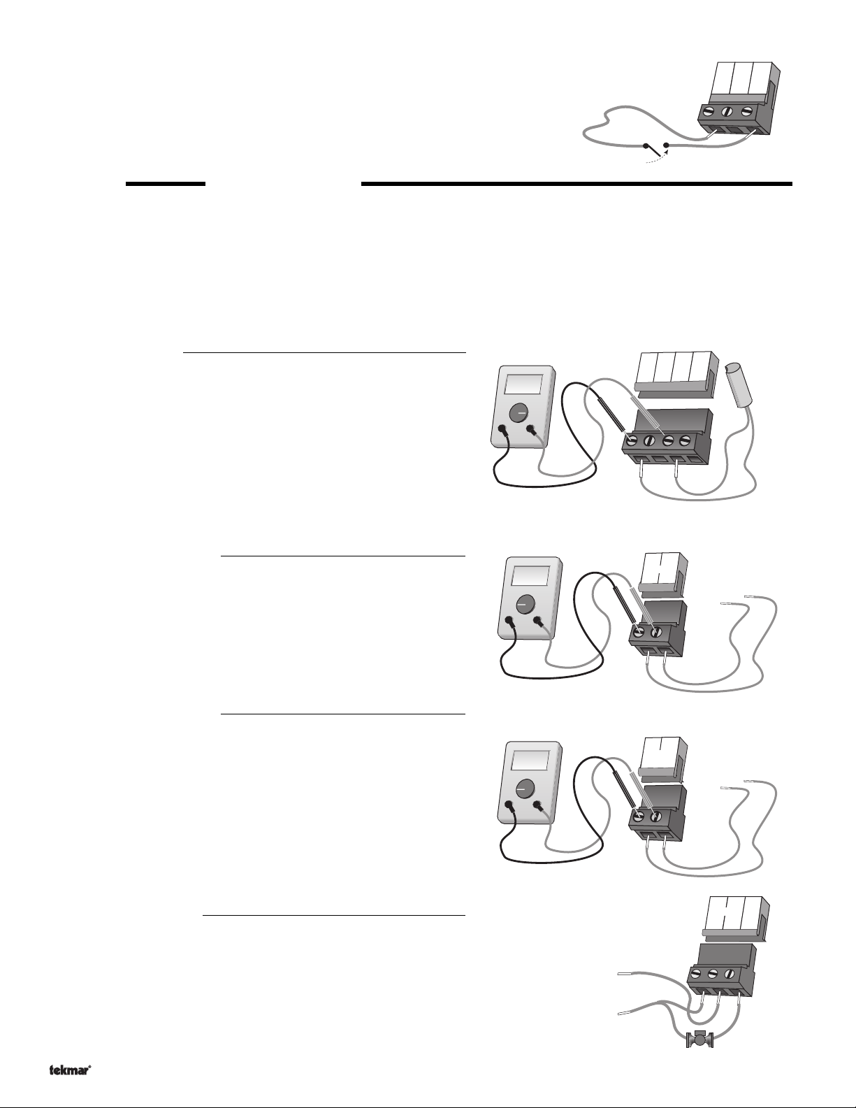
Ω
V
V
1
2
Mix
Demand
20 to 260 V (ac)
UnOccupied Switch
If an external timer (tekmar Timer 032) or switch is used, connect the two wires from
Com
and
the external switch to the
UnO Sw
terminals are shorted together, the control registers an UnOccupied signal.
Note: The setback override in the schedule menu of the control overrides any external
signal that is present on the UnOccupied Switch terminals.
terminals (14 and 16). When these two
Timer Switch
14
Com
15
10K
16
UnO
Sw
STEP FIVE
Each terminal block
TESTING THE WIRING
must be unplugged
from its header on the control before power is applied for testing. To remove the terminal block,
pull straight down from the control.
The following tests are to be performed using standard testing practices and procedures and should only be carried out by properly
trained and experienced persons.
A good quality electrical test meter, capable of reading from at least 0 - 300 V (ac) and at least 0 - 2,000,000 Ohms, is essential to properly
test the wiring and sensors.
Test The Sensors
In order to test the sensors, the actual temperature at each sensor
location must be measured. A good quality digital thermometer with a
surface temperature probe is recommended for ease of use and accuracy. Where a digital thermometer is not available, a spare sensor can
17
Com
18
Mix
Boil
20
19
Out
Ω
Ω
V
be strapped alongside the one to be tested and the readings compared.
Test the sensors according to the instructions in the Data Brochure D
070.
Test The Power Supply
Make sure exposed wires and bare terminals are not in contact with other
wires or grounded surfaces. Turn on the power and measure the voltage
between the N and L terminals (3 and 4) using an AC voltmeter, the
V
Ω
V
3
Power
N
4
L
108 to 132 V (ac)
reading should be between 108 and 132 V (ac).
Test The Powered Inputs
Mixing Demand
If a mixing demand is used, measure the voltage between the
Demand
terminals (1 and 2). When the mixing demand device calls for
heat, you should measure between 20 and 260 V (ac) at the terminals.
When the mixing demand device is off, you should measure less than
5 V (ac).
Testing The Outputs
Mix
3
Power
N
5
4
Mix
Pmp
L
Mixing Pump (Mix Pmp)
If a mixing pump is connected to the terminal (5), make sure that power to the terminal
block is off and install a jumper between the
5). When power is applied to the
pump should start. If the pump does not turn on, check the wiring between the terminal
block and pump and refer to any installation or troubleshooting information supplied with
the pump. If the pump operates properly, disconnect the power and remove the jumper.
Copyright © D 362 -12/08
Power N
Power L
and
Power L
and the
Mix Pmp
terminals (4 and
terminals (3 and 4), the mixing
18 of 36
L
120 V (ac)
N
Page 19
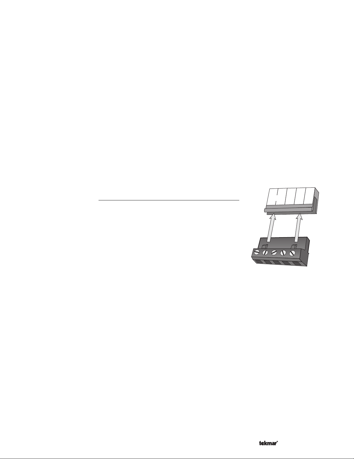
Boiler
If the boiler is connected to the
the terminals. When the boiler circuit is powered up, the boiler should fire. If the boiler does not turn on, refer to any installation or
troubleshooting information supplied with the boiler. (The boiler may have a flow switch that prevents firing until the boiler pump
is running.) If the boiler operates properly, disconnect the power and remove the jumper.
Boiler
terminals (6 and 7), make sure power to the boiler circuit is off and install a jumper between
Variable Speed Injection Pump
If a variable speed injection pump circuit is connected to the
the terminal block is off and install a jumper between the
circuit is powered up, the variable speed pump should operate at full speed. If the pump does not operate, check the wiring between
the terminal block and the pump and refer to any installation or troubleshooting information supplied with the pump. If the pump
operates properly, disconnect the power and remove the jumper.
Pwr Mix
Pwr Mix
and
and
Cls / Var
Cls / Var
terminals (8 and 10), make sure the power to
terminals (8 and 10). When the variable speed pump
Mixing Valve Actuator
If a floating action actuating motor circuit is connected to the
to the motor circuit is off and install a jumper between the
the actuator should move in the opening direction. If it does not, check the wiring between the terminals and the actuating motor.
Refer to any installation or troubleshooting information supplied with the motor. If the motor closes instead of opening, the wiring
of the actuating motor must be reversed. If the valve opens correctly, turn off the power to the circuit and remove the jumper. Install
a jumper between the
Pwr Mix
and
Cls / Var
terminals (8 and 10). When the circuit is powered up, the valve should move in the
closing direction. If it does not, check the wiring between the terminals and the actuating motor. Refer to any installation or
troubleshooting information supplied with the motor. If the motor closes correctly, turn off the power to the circuit and remove
the jumper.
Connecting The Control
Make sure all power to the devices and terminal blocks is off and remove any
remaining jumpers from the terminals.
Pwr Mix, Opn
Pwr Mix
and
, and
Cls / Var
Opn
terminals (8 and 9). When the circuit is powered up,
terminals (8, 9, and 10), make sure power
9
8
7
6
Boiler
Pwr
Mix
Opn
Cls/
Var
10
Reconnect the terminal blocks to the control by carefully aligning them with their respective
headers on the control and then pushing the terminal blocks into the headers. The terminal
blocks should snap firmly into place.
Install the supplied safety dividers between the unpowered sensor inputs and the powered
120 V (ac) or 24 V (ac) wiring chambers.
Apply power to the control. The operation of the control on power up is described in the
Sequence of Operation section of this brochure.
19 of 36
Copyright © D 362 -12/08
Page 20
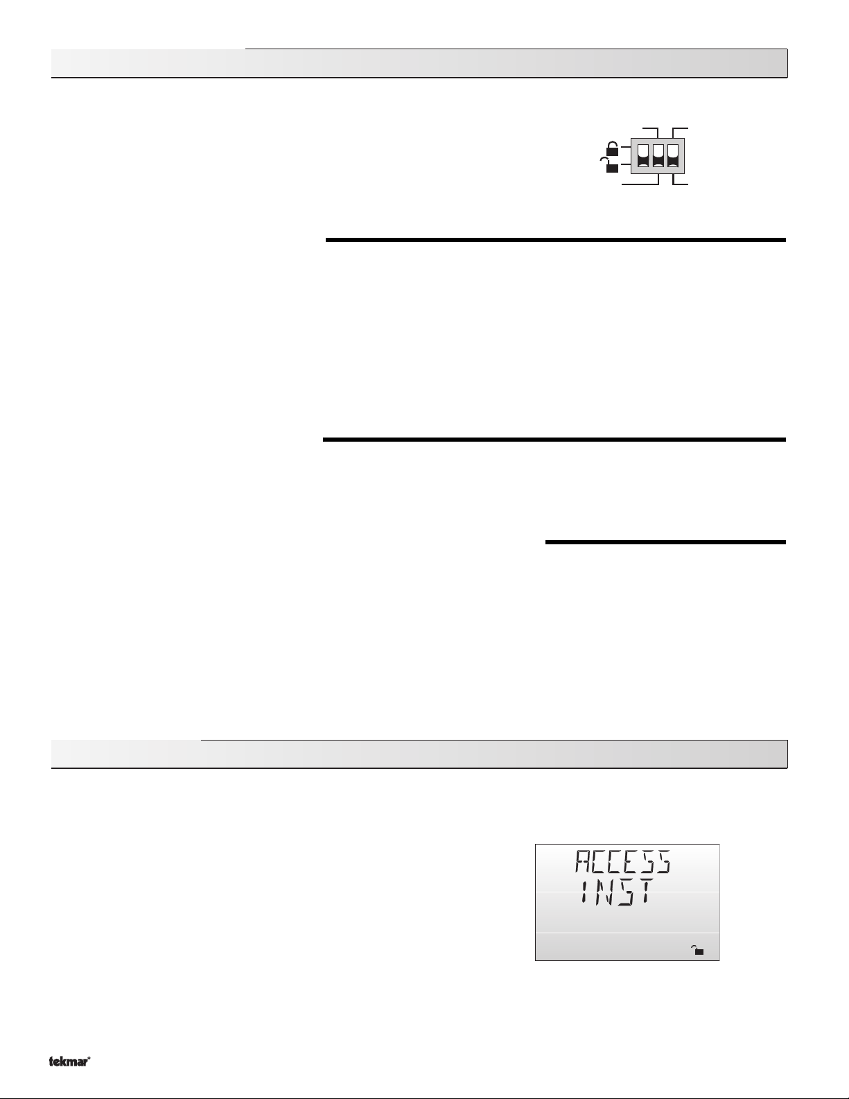
DIP Switch Settings
The DIP Switch settings on the control are very important and should be set to the appropriate
settings prior to making any adjustments to the control through the User Interface. The DIP
switch settings change the items that are available to be viewed and/ or adjusted in the User
Interface.
If a DIP switch is changed while the control is powered up, the control responds to the change
in setting by returning the display to the View menu. This is true for all of the DIP switches
except for the Lock / Unlock DIP switch.
Setback
None
Reset Ratio
Characterized
Heating Curve
LOCK / UNLOCK (FACTORY SETTING IS UNLOCK)
The
Lock / Unlock
DIP switch is used to lock and unlock the access level of the control and tekmar NetTM tN1 / tN2 device. Once locked,
access levels cannot be changed. To determine if the control is currently locked or unlocked, a small segment representing a padlock
is viewed in the bottom right hand corner of the display. When the padlock is closed, the access level cannot be changed.
To change the access level, set the DIP switch to the
Unlocked
, or
down
position. The current access level of the control or tekmar Net
(tN1 / tN2) device is viewed in its Miscellaneous (Misc) menu. While viewing the access level, use the up and down keys to select between
the Limited (LTD), User (USER), Installer (INST), or Advanced (ADV) access levels.
To lock the access level, select the appropriate access level in the Miscellaneous (Misc) menu and move the DIP switch from the
unlocked
Net
SETBACK / NONE (FACTORY SETTING IS NONE)
The
down position, the control ignores any external setback signal, and its user interface does not display the
When the DIP switch is set to the
setback signal generated on the
HEATING CURVE / RESET RATIO (FACTORY SETTING IS CHARACTERIZED HEATING CURVE)
The
switch is set to the
position to the
TM
(tN1 / tN2) device can no longer be viewed or adjusted in its Miscellaneous (Misc) menu.
locked
position. As long as the DIP switch is in the locked position, the access level of the control or tekmar
Setback / None
DIP switch enables and disables the setback functions of the control. When the DIP switch is set to the
Setback
UnO Sw
position, the setback features in the control are enabled. The control responds to an external
terminal.
Characterized Heating Curve / Reset Ratio
Characterized Heating Curve
DIP switch determines the type of Outdoor Reset that the control uses. When the DIP
setting, the control uses an Outdoor Reset method that matches the heating
UnOccupied
None
adjustments.
characteristics of the type of terminal unit that is being used. See Sequence Of Operation, Section A for a description of terminal units.
When this setting is used, a desired indoor air setting, design outdoor setting and a design supply setting must be entered into the control.
When the DIP switch is set to the
Reset Ratio
setting, the control uses an Outdoor Reset method that varies the supply setting based
only on the outdoor air temperature. When this setting is used, the starting water setting and OUT STRT temperature determines the
beginning point of the reset ratio. The design supply setting and the design outdoor setting determines the ending point of the reset ratio.
All temperatures between these two points fall on a straight line connecting these points.
TM
or
Important: Once the control is programmed, this DIP switch should not be adjusted as the settings may change.
Access Levels
The tekmar Mixing Control 362 comes with four Access Level settings.
These Access Levels restrict the number of Menus, Items, and Adjustments
that can be accessed by the user. The four access levels are Limited (LTD),
User (USER), Installer (INST) and Advanced (ADV).
The access level of the control is found in the Miscellaneous (
when the
Lock/Unlock
DIP switch is set to the
Unlocked
Advanced access level, all of the control settings are available to the user.
In the User access level, only a few of the menus and items are available.
The Limited access level is the most restricted of them all. The control’s
factory setting is Installer (
INST
). This access level is sufficient for the
normal set up of the control. Once the control is set up, the appropriate
access level should be selected for the people that deal with the control on
a regular basis.
Copyright © D 362 -12/08
Misc
) menu
position. In the
20 of 36
Misc
Page 21
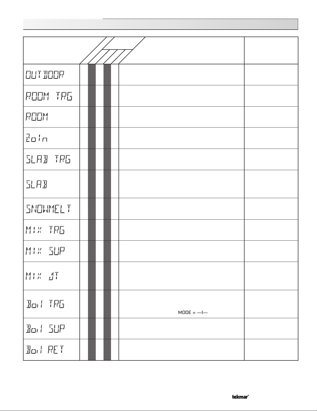
362 View Menu (1 of 1)
Access
Level
DescriptionItem Field
Range
LTD
Section
• • • •
B2
B2
• • • •
B2
C3
B2
C1
• • • •
INST
USER
• • •
•
•
• •
ADV
Current outdoor air temperature as measured by the outdoor
sensor. This is also the default display for the control.
Target room air temperature. “– – –” denotes no heat is
required.
10K = INDR MODE = —1—
Measured room air temperature at the indoor sensor.
10K = INDR MODE = —1—
This is the signal that is being received from a tekmar Zone
Control.
10K = ZoIn MODE = —1—
Slab sensor target temperature. This is the temperature
that the control is trying to maintain at the slab sensor.
10K = SLAB MODE = —2—
Current slab sensor temperature.
10K = SLAB
MIX MIN = OFF
Current operating status of the snow melting system.
MODE = —2—
-67 to 149˚F
(-55 to 65˚C)
- - -, 35 to 100˚F
(2 to 38˚C)
-58 to 167˚F
(-50 to 75˚C)
- - -, 35 to 110˚F
(2 to 43˚C)
- - -, -58° to 167˚F
(-50 to 75˚C)
-58 to 167˚F
(-50 to 75˚C)
STRT, STOP, IDLE, EXT,
0:00 to 17:00 hr, - - -,
INF, WWSD, CWCO
Installation, Testing
Installation, Electrical
B1
A
B1
C1
C1
D1
D1
D2
• •
• • •
• •
• •
• • •
• • •
Target mixed supply is the temperature the control is
currently trying to maintain at the mixing sensor.
Current mixed supply water temperature as measured by
the mixing sensor.
Current mixed ∆T difference between the mixed supply
sensor and the mixed return sensor.
∆T MAX ≠ OFF
Boil SENS ≠ SUP MODE = —2—
Target boiler supply is the temperature the control is currently
trying to maintain at the boiler sensor +/- 1/2 of the
differential.
BOIL SENS = SUP MODE = —1—
Current boiler supply water temperature as measured by
the boiler sensor.
BOIL SENS = SUP
Current boiler return water temperature as measured by
the boiler sensor.
BOIL SENS = RET
- - -, -25 to 248˚F
(-32 to 120˚C)
-31 to 266˚F
(-35 to 130˚C)
-85 to 170˚F
(-65 to 77˚C)
- - -, -31 to 266˚F
(-35 to 130˚C)
-31 to 266˚F
(-35 to 130˚C)
-31 to 266˚F
(-35 to 130˚C)
21 of 36
Copyright © D 362 -12/08
Page 22
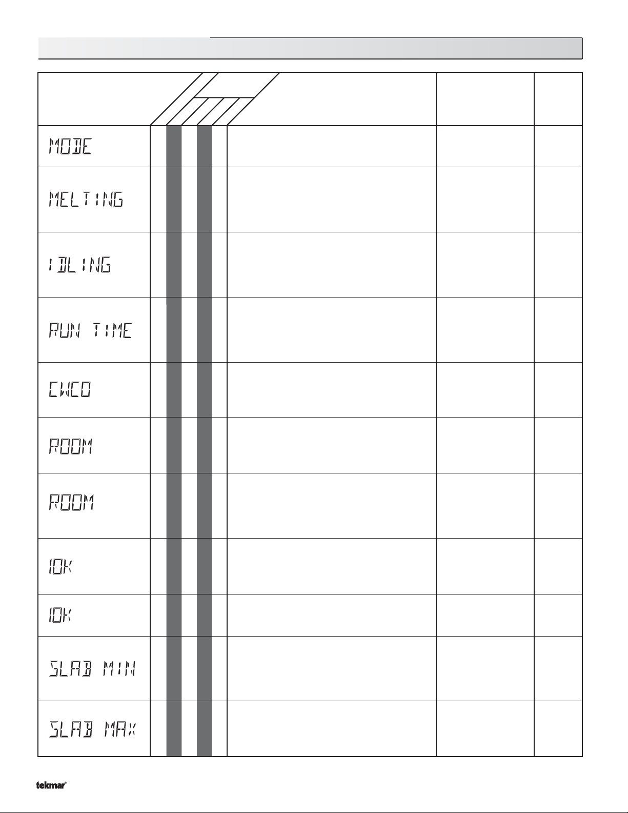
362 Adjust Menu (1 of 4)
LTD
Section
A
C3
C4
C3
C4
C1
• • •
• • • •
USER
• •
• •
Access
Level
DescriptionItem Field
ADV
INST
The operating Mode for the control. MODE 1 is
for Heating. MODE 2 is for Snow Melting.
This item is the desired slab surface temperature
while in the Melting Mode.
MODE = —2—
This item is the desired slab surface temperature
while in the Idling Mode.
MODE = —2—
The time for which the slab is operated once it
has reached the MELTING temperature. Wit h-
out slab sensor, countdown starts immediately.
This item cannot be viewed if a Remote Start /
Stop Module 039 has been connected.
MODE = —2—
Range
—1— (Heating)
—2— (Snow Melting)
Default = —1—
32 to 95°F
(0 to 35°C)
Default = 36°F (2°C)
OFF,
20 to 95°F or 120°F
(OFF, -7 to 35°C)
Default = OFF
OFF, 0:30 to 17:00 hr
INF (Infinity)
Default = 4:00 hr
Actual
Setting
Occ
UnOcc
C1
B1
• • • •
B1
B2
C3
C4
B2
B2
• •
• • •
• •
• •
• • •
• •
The Cold Weather Cut Off temperature for the
snow melting system.
MODE = —2—
The desired room air temperature during an
Occupied period.
adjustment in the LTD access level.
DIP switch =
RTU = NONE MODE = —1—
The desired room air temperature during an
UnOccupied period.
DIP switch =
DIP switch =
RTU = NONE MODE = —1—
The device that is to be connected to the 10K
input terminal.
DIP switch =
RTU = NONE MODE = —1—
Selects if a slab sensor is connected to the control.
MODE = —2—
The minimum temperature at the slab sensor as
long as the control is not in WWSD.
DIP switch =
10K = SLAB
MIX MIN = OFF
RTU = NONE MODE = —1—
The maximum temperature at the slab sensor.
DIP switch =
10K = SLAB
RTU = NONE MODE = —1—
Note:
There is only a ±3°F
Characterized Heating Curve
Characterized Heating Curve
Setback
Characterized Heating Curve
Characterized Heating Curve
Characterized Heating Curve
OFF, -30 to 50°F
(OFF, -34 to 10°C)
Default = 10°F (-12°C)
35 to 100°F
(2 to 38°C)
Default = 70°F (21°C)
35 to 100°F
(2 to 38°C)
Default = 65°F (18°C)
NONE, INDR, ZoIn,
SLAB (only if MIX
MIN = Off)
Default = NONE
NONE, SLAB
Default = SLAB
OFF, 35 to 120°F
(OFF, 2 to 49°C)
Default = 70°F (21°C)
40 to 150°F
(4 to 66°C)
Default = 90°F (32°C)
Copyright © D 362 -12/08
22 of 36
Page 23
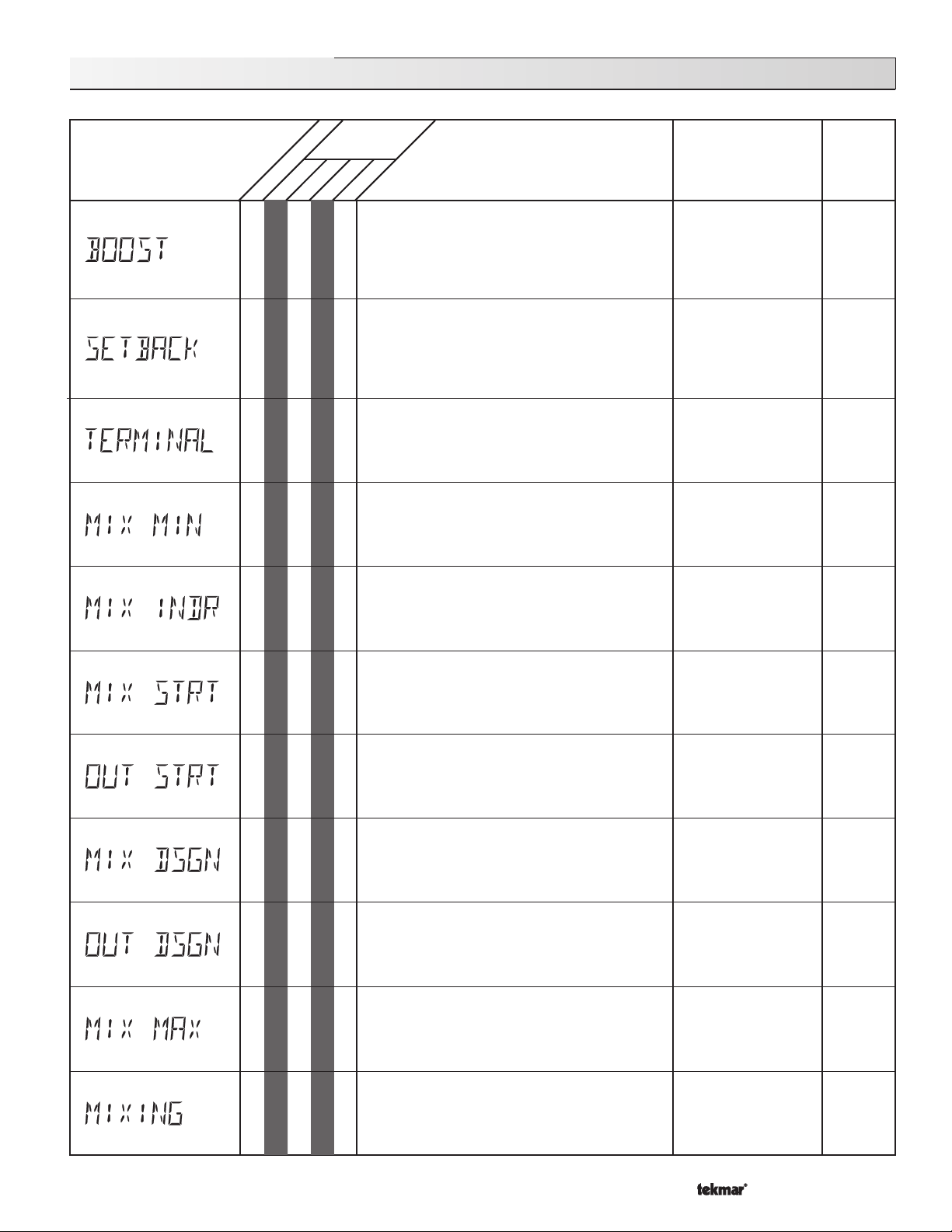
362 Adjust Menu (2 of 4)
for the mixing system.
LTD
Section
B1
B1
B1
• • •
INST
USER
• •
• •
Access
Level
DescriptionItem Field
ADV
The maximum length of morning boost.
DIP switch =
DIP switch =
No RTU Connected
10K ≠ ZoIn MODE = —1—
The amount the mixing supply temperature is
reduced when the control is in the
UnOccupied Mode.
DIP switch =
DIP switch =
MODE = —1—
The type of terminal units that are being used in
the heating system.
DIP switch =
MODE = —1—
Characterized Heating Curve
Setback
Reset Ratio
Setback
Characterized Heating Curve
Range
0:20 to 8:00 hrs
Default = OFF
0 to 50˚F
(0 to 28˚C)
Default = 15°F (-9°C)
HRF1 (Heavy), HRF2
(Light), (Fan-) COIL,
CONV (ector), RAD
(iator), BASE (board)
Default = HRF1
Actual
Setting
B1
B1
B1
B1
B1
B1
•
• •
• •
• •
• •
• •
The minimum supply water temperature for the
mixing system.
DIP switch =
MODE = —1—
The design indoor air temperature used in the
heat loss calculations for the heating system.
DIP switch =
MODE = —1—
The starting water temperature used in the Reset
Ratio calculation for the heating system.
DIP switch =
MODE = —1—
The outdoor starting temperature used in the
reset ratio calculation for the heating system.
DIP switch =
MODE = —1—
The design supply water temperature used in the
heat loss calculation for the heating system.
MODE = —1—
The design outdoor air temperature used in the
heat loss calculation for the heating system
MODE = —1—
Characterized Heating Curve
Characterized Heating Curve
Reset Ratio
Reset Ratio
OFF, 35 to 150˚F
(OFF, 2 to 66˚C)
Default = OFF
35 to 100˚F
(2 to 38˚C)
Default = 70°F (21°C)
35 to 150˚F
(2 to 66˚C)
Default = 70°F (21°C)
35 to 85˚F
(2 to 29˚C)
Default = 70°F (21°C)
70 to 220˚F
(21 to 104˚C)
Default = 120°F (49°C)
-60 to 32˚F
(-51 to 0˚C)
Default = 10°F (-12°C)
A
B1
A
• •
• •
The maximum supply temperature allowed
The type of mixing device that is to be used.
23 of 36
80 to 210˚F, OFF
(27 to 99˚C, OFF)
Default = 140°F (60°C)
FLOT (Floating),
VAR (Variable speed)
Default = VAR
Copyright © D 362 -12/08
Page 24
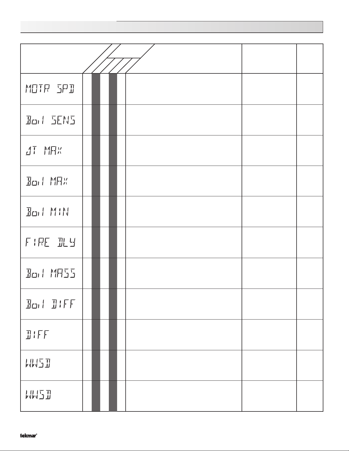
362 Adjust Menu (3 of 4)
LTD
Section
USER
Access
Level
ADV
INST
DescriptionItem Field
Range
Actual
Setting
A
D1
D2
D3
C1
D1
D1
D1
• •
• •
• •
• •
• •
The time that the actuating motor requires to
operate from fully closed to fully open.
MIXING = FLOT
The location of the boiler sensor. This affects
operation of the boiler contact.
The maximum ∆T for the snow melting slab.
Boil SENS ≠ SUP MODE = —2—
The maximum temperature allowed for the boiler
target temperature.
•
Boil SENS = SUP MODE = —1—
The minimum temperature allowed for the boiler
target temperature.
Boil SENS ≠ NONE
The time delay the control can expect between
the time the boiler contact closes and the
burner fires.
Boil SENS = SUP
30 to 230 sec
Default = 160 sec
SUP (Supply)
RET (Return)
NONE
Default = SUP
10 to 70˚F, OFF
(5 to 39˚C, OFF)
Default =40°F (22°C)
120 to 225˚F, OFF
(49 to 107˚C, OFF)
Default = 210°F (99°C)
OFF, 80 to 180˚F
(OFF, 27 to 82˚C)
Default = 140°F (60°C)
0:00 to 3:00 min
(1 sec. increments)
Default = 0:10 min
Occ
UnOcc
D1
D1
D1
B1
C4
B1
• •
• •
• •
• • •
• •
The thermal mass characteristics of the boiler that
is being used.
Boil SENS = SUP
The differential that the control is to use when it
is operating the boiler.
Boil SENS =
The differential for the snow melting system.
Boil SENS =
The system’s warm weather shut down during the
Occupied period.
The system’s warm weather shut down during the
UnOccupied period.
DIP switch =
MODE = —1—
SUP MODE = —1—
SUP
Setback
MODE = —2—
LITE, MED, HEVY
Default = MED
AUTO, 2 to 42˚F
(AUTO, 1 to 23˚C)
Default = AUTO
AUTO, 2 to 42˚F
(AUTO, 1 to 23˚C)
Default = AUTO
35 to 100˚F, OFF
(2 to 38˚C, OFF)
Default =70°F (21°C)
35 to 100˚F, OFF
(2 to 38˚C, OFF)
Default =60°F (4°C)
Copyright © D 362 - 12/08
24 of 36
Page 25
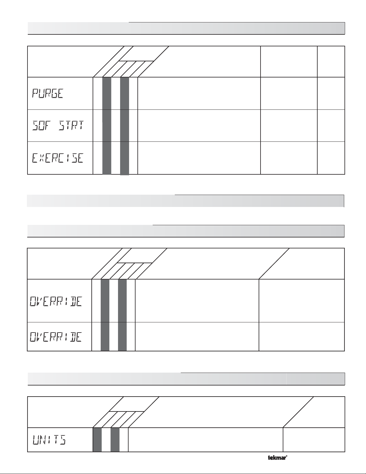
362 Adjust Menu (4 of 4)
LTD
Section
USER
Access
Level
ADV
INST
DescriptionItem Field
Range
Actual
Setting
B1
C1
B1
A
The maximum length of time that the mixing pump
continues to operate after the mix demand
•
is removed.
Enables or disables the Soft Start feature in
the control.
•
MODE = —1—
The frequency with which the control exercises the
pumps and valves that are operated by the control.
•
362 Monitor Menu (see pages 30 - 32)
362 Schd (Schedule) Menu (1 of 1)
Access
Level
OFF, 0:10 to 40:00 min
Default = 0:20 min
NONE, MIX
Default = NONE
30 to 240 hr, OFF
Default = 70 hr
DescriptionItem Field
Range
ADV
INST
USER
LTD
Section
The type of setback override that is in effect for
the heating system.
B1
• • • •
C1
• • • •
DIP switch =
MODE = —1—
AWAY is available even if DIP ≠ Setback
The override that is in effect for the snow melting
system.
MODE = —2—
362 Misc (Miscellaneous) Menu (1 of 2)
Access
Level
ADV
INST
USER
LTD
The units of measure that all of the temperatures are to be
• • •
displayed in by the control.
Setback
NONE, TMPY Occ Ovr, PERM
Occ Ovr, TMPY UnOcc Ovr,
PERM UnOcc Ovr, AWAY Ovr
Default =NONE
NONE, AWAY
Default =NONE
DescriptionItem Field
˚F, ˚C
Default = °F
Range
25 of 36
Copyright © D 362 - 12/08
Page 26
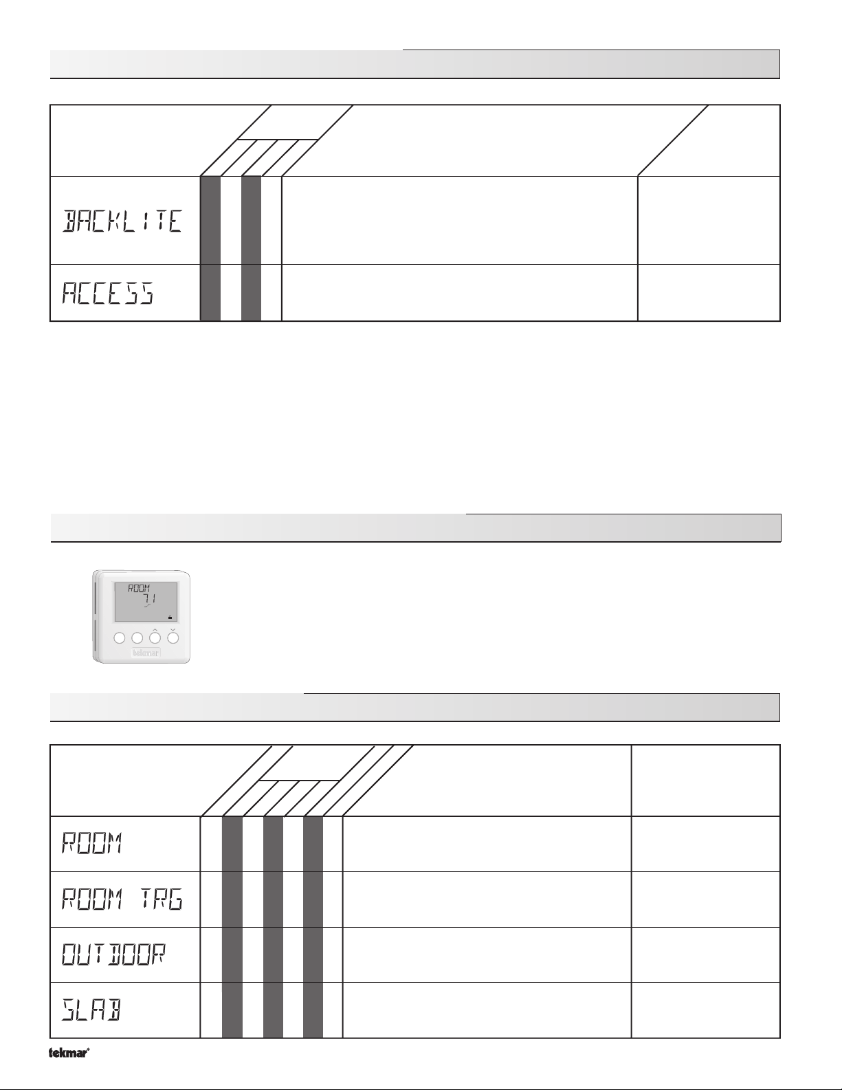
362 Misc (Miscellaneous) Menu (2 of 2)
Access
Level
DescriptionItem Field
Range
LTD
• • •
• • • •
USER
ADV
INST
The operating mode for the back lighting on the LCD as well
as the time of keypad inactivity until the control automatically
returns to the default display.
BACKLITE = OFF (returns after 10 seconds)
BACKLITE = 30 sec (returns after 30 seconds)
BACKLITE = ON (returns after 90 seconds)
The access level that is to be used by the control.
DIP switch =
Unlock
Room Temperature Units (RTUs) 062 and 063
OFF, 30 sec, ON
Default = ON
ADV, INST, USER, LTD
Default = INST
View
°
F
UnOcc 1
Heat
ItemMenu
362 RTU View Menu (1 of 1)
RTU View Menu
B2
B2
A single RTU may be connected to the Mixing Control 362 in order to provide the control with indoor
temperature feedback for the mixing side of the heating system (Refer to Essay E 002). When using
an RTU, several items related to the mixing side of the heating system are no longer available in the
control’s User Interface. These items are available only in the RTU’s User Interface. Also, the number
of items that are available on the RTU depends on the type of RTU that is connected to the control.
Access
Level
Range
- - -, 14 to 167˚F
(-10 to 75˚C)
- - -, 35 to 100˚F
(2 to 38˚C)
-67 to 149˚F
(-55 to 65˚C)
LTD
Section
USER
INST
ADV
• • • • • •
• • • • •
• • • • • •
062
063
RTU
RTU
Current room air temperature.
RTU SENS = AIR
Target room air temperature.
RTU SENS = AIR
Current outdoor air temperature.
DescriptionItem Field
B2
Copyright © D 362 -12/08
• ••
•
Current slab (floor) sensor temperature.
REMOTE 3 = SLAB
26 of 36
-58 to 167˚F
(-50 to 75˚C)
Page 27
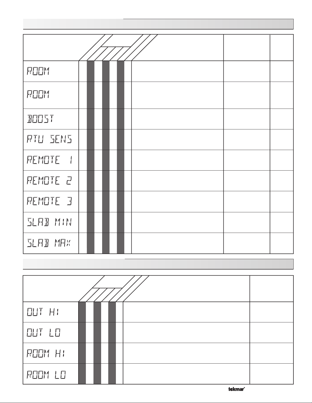
362 RTU Adjust Menu (1 of 1)
Access
Level
Occ
UnOcc
LTD
Section
B1
• • • • • •
B1
• • • • • •
B1
ADV
INST
USER
• • • •
062
063
RTU
RTU
The desired room air temperature during
an Occupied period for the mixing zones.
Note:
There is only a ±3°F adjustment in
the LTD access level.
The desired room air temperature during
an UnOccupied period for mixing zones.
Note:
There is only a ±3°F adjustment in
the LTD access level.
DIP switch =
The amount of morning boost.
DIP switch =
DescriptionItem Field
Setback
Setback
Range
35 to 100˚F
(2 to 38˚C)
Default = 70°F (21°C)
35 to 100˚F
(2 to 38˚C)
Default = 65°F (18°C)
OFF, 0:20 to 8:00 hr
Default = OFF
Actual
Setting
• • • •
• ••
• ••
• ••
• • ••
• ••
362 RTU Monitor Menu (1 of 1)
Access
Level
LTD
USER
INST
ADV
RTU
• • • • • •
Selects whether the RTU is to use its internal
air sensor.
This item allows for remotely adding a 10K
sensor to the RTU. Applications are for
temperature averaging.
This item allows for remotely adding a
second 10K sensor to the RTU. Applications
are for temperature averaging.
This item allows for remotely adding a third
10K air sensor to the RTU, or a 10K slab
sensor to measure slab temperature.
MIX MIN = OFF
The minimum target temperature at the slab
sensor when not in WWSD.
REMOTE 3 = SLAB
The maximum target temperature at the slab
sensor.
REMOTE 3 = SLAB
063
062
RTU
The highest outdoor air temperature recorded since this
item was last cleared.
To clear, press & hold the
(for Slab Sensor only)
DescriptionItem Field
UP & DOWN
buttons
OFF, AIR
Default = AIR
NONE, AIR
Default = NONE
NONE, AIR
Default =
NONE, AIR, SLAB
Default = NONE
OFF, 35 to 120°F
(OFF, 2 to 49°C)
Default = 70°F (21°C)
40 to 150°F
(4 to 66°C)
Default = 90°F (32°C)
NONE
Range
-67 to 149˚F
(-55 to 65˚C)
• • • • • •
• • • • •
• • • • •
The lowest outdoor air temperature recorded since this
item was last cleared.
To clear, press & hold the
The highest room air temperature recorded since this item
was last cleared.
To clear, press & hold the
The lowest room air temperature recorded since this item
was last cleared.
To clear, press & hold the
27 of 36
UP & DOWN
UP & DOWN
UP & DOWN
buttons
buttons
buttons
-67 to 149˚F
(-55 to 65˚C)
14 to 167˚F
(-10 to 75˚C)
14 to 167˚F
(-10 to 75˚C)
Copyright © D 362 -12/08
Page 28
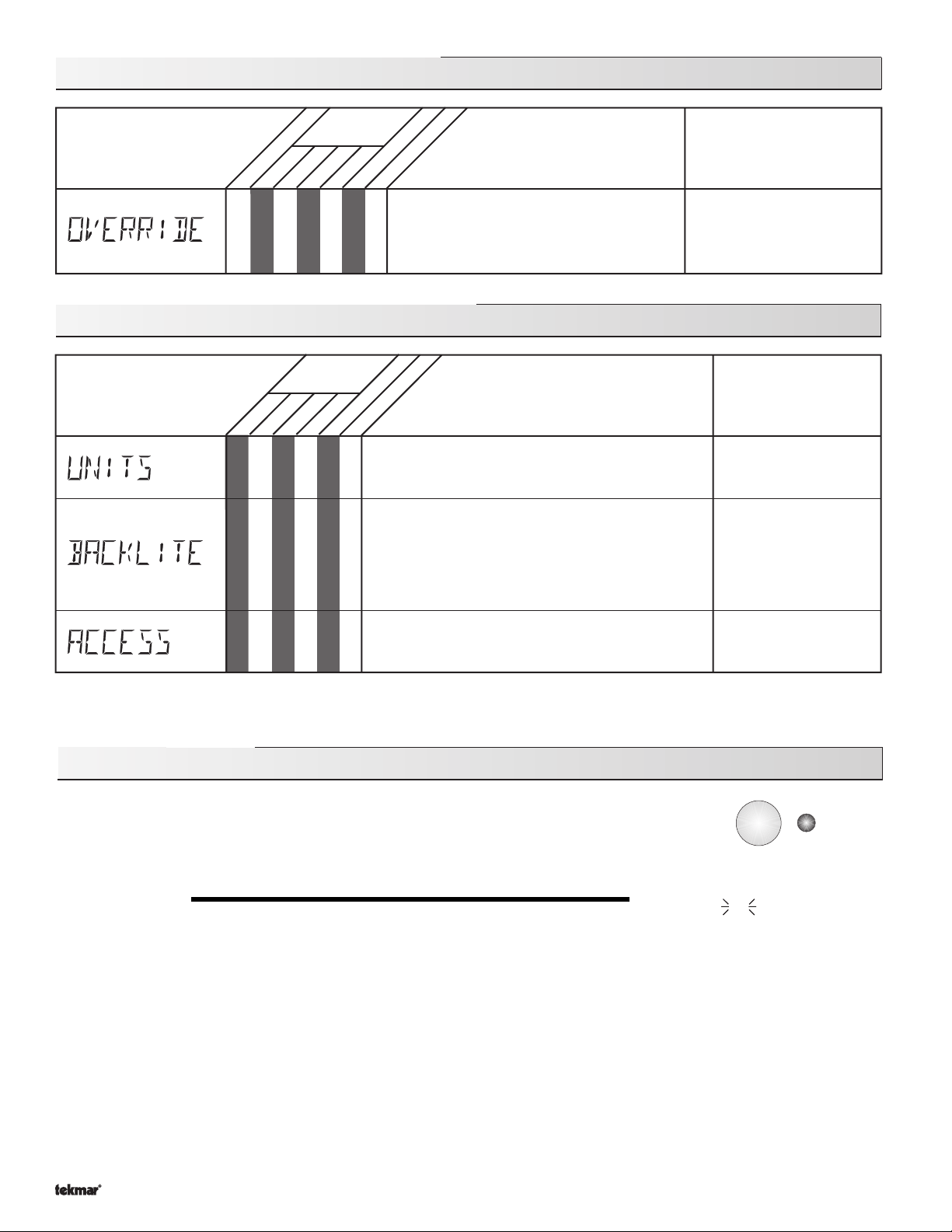
362 RTU Schd (Schedule) Menu (1 of 1)
Access
Level
063
062
Section
B1
LTD
ADV
INST
USER
• • • •
RTU
RTU
The type of setback override that is in effect.
DIP switch =
Away is available even if DIP ≠ Setback
362 RTU Misc (Miscellaneous) Menu (1 of 1)
Access
Level
063
062
LTD
• • • • •
• • • • •
USER
INST
ADV
RTU
RTU
The units of measure that all of the temperatures are
to be displayed in the RTU.
The operating mode for the back lighting on the LCD
as well as the time of keypad inactivity until the RTU
automatically returns to the view menu.
BACKLITE = OFF (returns after 10 seconds)
BACKLITE = 30
BACKLITE = ON (returns after 90 seconds)
DescriptionItem Field
Setback
DescriptionItem Field
sec (returns after 30 seconds)
Range
NONE, TMPY Occ Ovr, PERM
Occ Ovr, TMPY UnOcc Ovr,
PERM UnOcc Ovr, AWAY Ovr
Default = NONE
Range
˚F, ˚C
Default = °F
OFF, 30 sec, ON
Default = 30 sec
The access level that is to be used by the RTU.
• • • • • •
DIP switch =
Unlock
Testing the Control
The Mixing Control 362 has a built in test routine which is used to test the main control
functions. The 362 continually monitors the sensors and displays an error message whenever
a fault is found. See the following pages for a list of the 362’s error messages and possible
causes. When the
relays are tested in the following test sequence.
TEST SEQUENCE
Each step in the test sequence lasts 10 seconds.
During the test routine, the test sequence is paused by pressing the
well as the word PAUS. If the
test routine. If the test sequence is paused, the
to rapidly advance through the test sequence. To reach the desired step, repeatedly press and release the
appropriate device and segment in the display turn on.
Step 1
test
button is pressed, the test light is turned on. The individual outputs and
Test
button. While paused, the control displays the testing step as
Test
button is not pressed again for 5 minutes while the test sequence is paused, the control exits the entire
Test
button can be pressed again to advance to the next step. This can also be used
- If FLOT is selected in the MIXING item, the mixing valve is run fully open. If VAR is selected in the MIXING item, the injection
pump is ramped up over 10 seconds to 100%.
Test
ADV, INST, USER, LTD
Default = INST
off
not testing
red
testing
red
testing paused
Test
button until the
Step 2
Step 3
- If FLOT is selected in the MIXING item, the mixing valve is run fully closed. If VAR is selected in the MIXING item, the injection
pump is ramped down over 10 seconds.
- The mixing pump
in step 3.
Copyright © D 362 -12/08
(Mix Pmp)
is turned on for 10 seconds.
28 of 36
NOTE:
Only if there is a mixing demand can the control be paused
Page 29
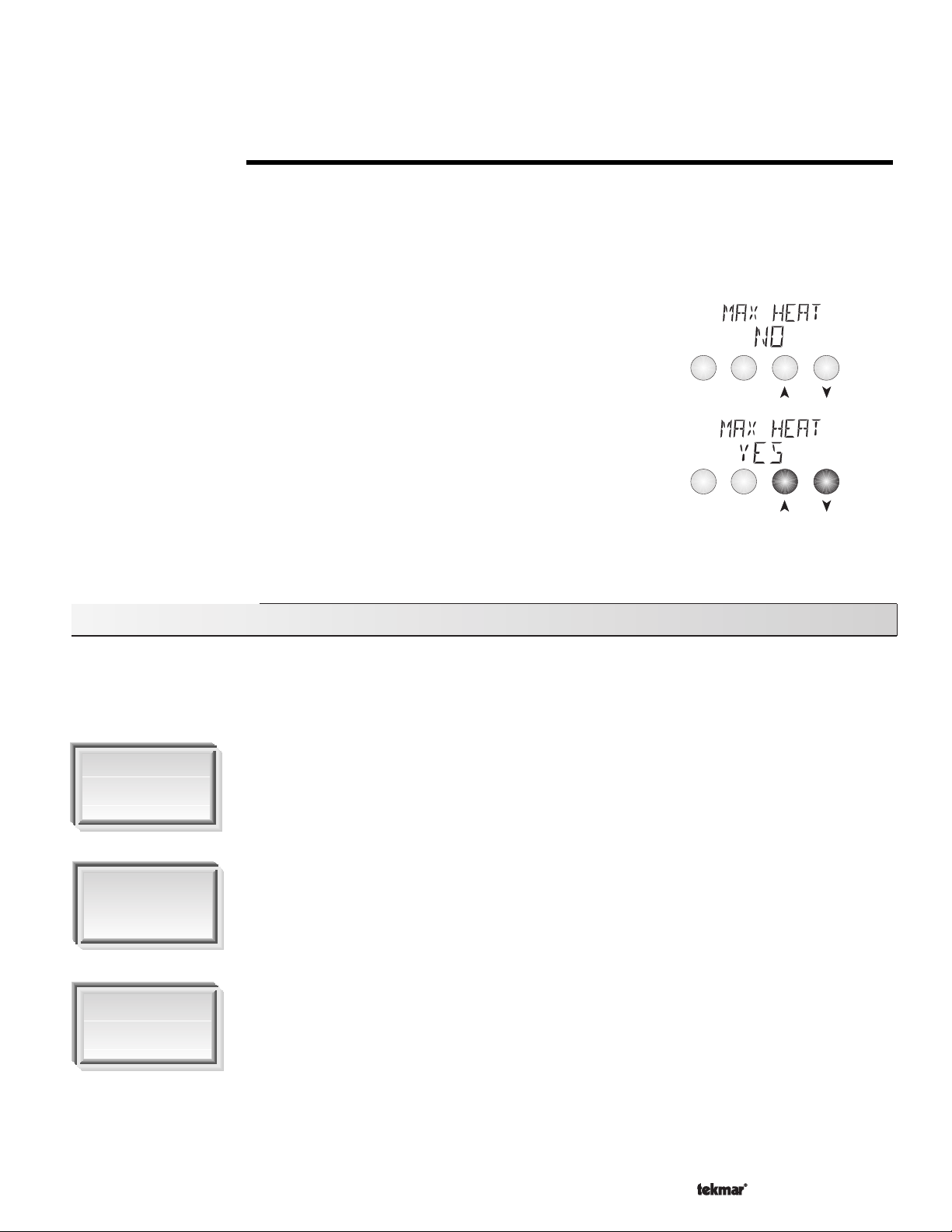
Step 4
- The
NOTE:
Boiler
contact is turned on for 10 seconds. After 10 seconds, the
Only if there is a boiler demand can the control be paused in step 4.
Boiler
and
Mix Pmp
contacts are shut off.
Step 5
MAX HEAT (MAX HEAT)
The Mixing Control 362 has a function called Max Heat. In this mode, the 362 turns on and operates the system up to the maximum
set temperatures, and the mixing device at the set percentage, as long as there is a demand for heat. The control continues to operate
in this mode for up to 24 hours or until either the Item, Menu or Test button is pressed. This mode may be used for running all circulators
during system start-up in order to purge air from the piping. To enable the Max Heat feature, use the following procedure.
1) Press and hold the Test button for more than 3 seconds. At this point, the control
2) Using the Up or Down buttons, select the word YES. After 3 seconds, the control flashes
3) Set the desired output of the mixing device by using the Up and / or Down buttons on
4) To cancel the
5) Once the
- After the test sequence is completed, the word COMPLETE is displayed for 1 second and the control resumes its
normal operation.
displays the words MAX HEAT and the word NO.
the word MANUAL and the number 100. This number represents the desired output from
the mixing device.
the control.
Max Heat
Max Heat
normal operation.
mode, press either the Item, Menu, or Test button.
mode has either ended or is cancelled, the control resumes
Menu
Menu
Item
Item
or
Troubleshooting
When troubleshooting any heating system, it is always a good idea to establish a set routine to follow. By following a consistent routine,
many hours of potential headaches can be avoided. Below is an example of a sequence that can be used when diagnosing or
troubleshooting problems in a hydronic heating system.
Establish the
Problem
Establish the problem. Get as much information from the customer as possible about the problem.
Is there too much heat, not enough heat, or no heat? Is the problem only in one particular zone or
area of the building or does the problem affect the entire system? Is this a consistent problem or only
intermittent? How long has the problem existed for? This information is critical in correctly
diagnosing the problem.
Understand the
Sequence of
Operation
Use the Test
Routine
Understand the sequence of operation of the system. If a particular zone is not receiving enough
heat, which pumps or valves in the system must operate in order to deliver heat to the affected zone?
If the zone is receiving too much heat, which pumps, valves or check valves must operate in order
to stop the delivery of heat?
Press the Test button on the control and follow the control through the test sequence as described
in the Testing section. Pause the control as necessary to ensure that the correct device is operating
as it should.
29 of 36
Copyright © D 362 -12/08
Page 30
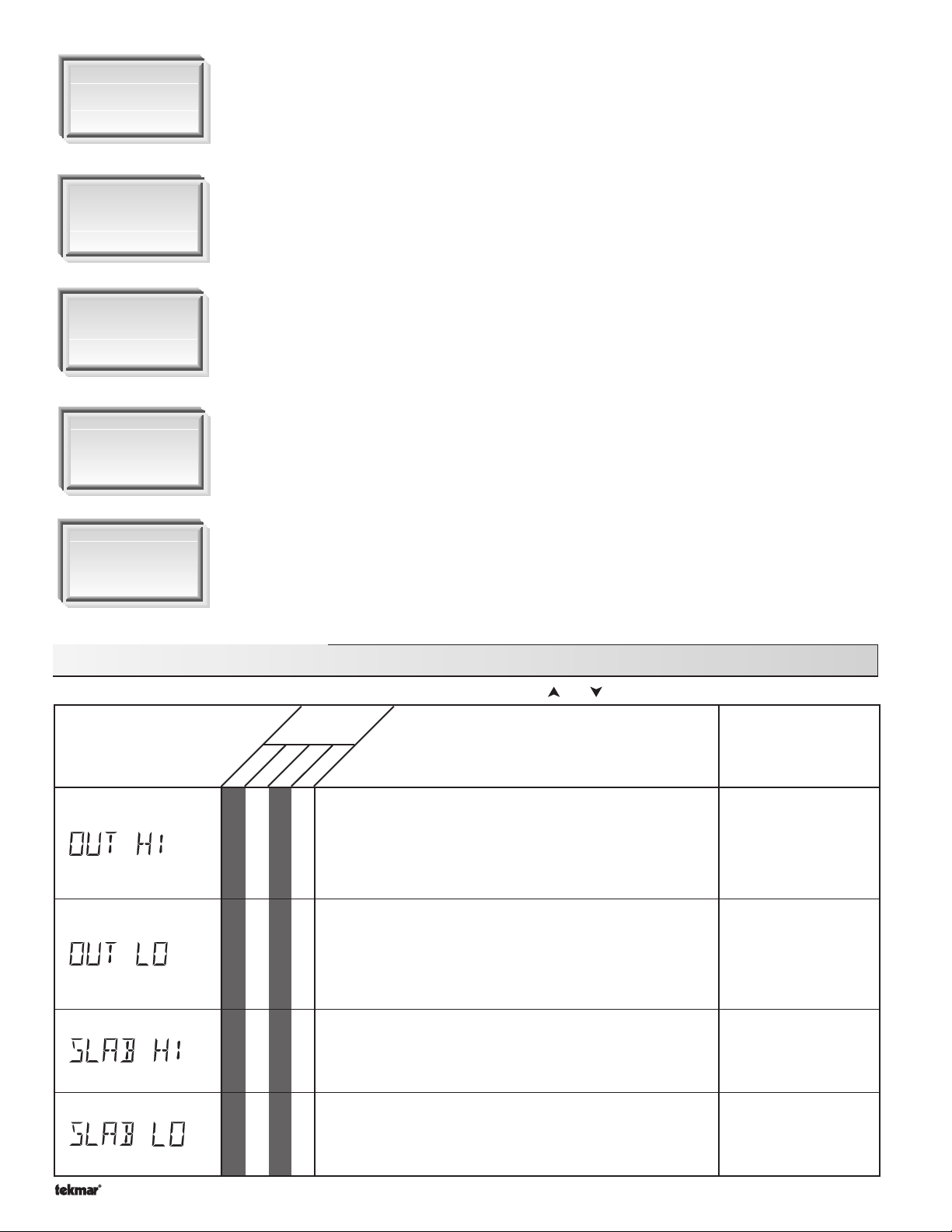
Sketch the
Piping in the
System
Document the
Control
Isolate the
Problem
Test the Contacts
Voltages &
Sensors
Sketch the piping of the system. This is a relatively simple step that tends to be overlooked,
however it can often save hours of time in troubleshooting a system. Note flow directions in the
system paying close attention to the location of pumps, check valves, pressure bypass valves
and mixing valves. Ensure correct flow direction on all pumps. This is also a very useful step if
additional assistance is required.
Document the control for future reference. Before making any adjustments to the control, note
down all of the items that the control is currently displaying. This includes items such as error
messages, current temperatures and settings, and which devices should be operating as
indicated by the LCD. This information is an essential step if additional assistance is required
to diagnose the problem.
Isolate the problem between the control and the system. Now that the sequence of operation
is known and the system is sketched, is the control operating the proper pumps and valves at
the correct times? Is the control receiving the correct signals from the system as to when it
should be operating? Are the proper items selected in the menus of the control for the device
that is to be operated?
Test the contacts, voltages and sensors. Using a multimeter, ensure that the control is receiving
adequate voltage to the power terminals and the demand terminals as noted in the technical
data. Use the multimeter to determine if the internal contacts on the control are opening and
closing correctly. Follow the instructions in the Testing the Wiring section to simulate closed
contacts on the terminal blocks as required. Test the sensors and their wiring as described in
the sensor Data Brochures.
Monitor the
System
Monitor the system over a period of time. Select the applicable items in the Monitor menu of
the control and reset them to zero. Allow the system and the control to operate over a known
period of time and then record the Monitor items. Use this information to help diagnose any
remaining problems.
362 Monitor Menu (1 of 3)
Note
: To clear the recorded Information in the specific item field, press and hold and .
Access
Level
DescriptionItem Field
LTD
• • • •
• • • •
INST
USER
ADV
The highest recorded outdoor air temperature since this item
was last cleared. This can be used to diagnose if the Outdoor
Sensor 070 has been located correctly. If this reading is too
high, the 070 may be located in a location that receives direct
sun light or is influenced by an exhaust vent.
The lowest recorded outdoor air temperature since this item
was last cleared. This can be used to diagnose if the Outdoor
Sensor 070 has been located correctly. If this reading is too
high, there may not be adequate insulation behind the 070, or
it may be located too close to an exhaust vent.
Range
-67 to 149˚F
(-55 to 65˚C)
-67 to 149˚F
(-55 to 65˚C)
Copyright © D 362 -12/08
• • •
• • •
The highest recorded temperature at the slab sensor since this
item was last cleared.
10K = SLAB
The lowest recorded temperature at the slab sensor since the
item was last cleared.
10K = SLAB
30 of 36
-58 to 167˚F
(-50 to 75˚C)
-58 to 167˚F
(-50 to 75˚C)
Page 31
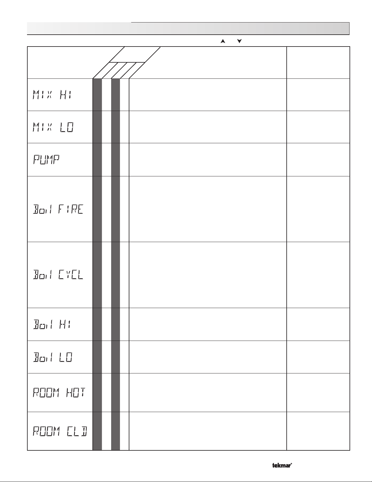
362 Monitor Menu (2 of 3)
Note
: To clear the recorded Information in the specific item field, press and hold and .
Access
Level
DescriptionItem Field
Range
LTD
USER
• •
• •
• •
• •
ADV
INST
The highest recorded temperature at the mixing sensor since
this item was last cleared.
The lowest recorded temperature at the mixing sensor since
this item was last cleared.
The total number of mixing pump
since this item was last cleared.
The total number of hours the boiler has been firing since this
item was last cleared. The boiler running time may be longer
since this firing time does not include the FIRE DLY time set in
the Adjust menu. This item can be used to determine if the
boiler has been oversized or undersized for the attached heating
load. If the boiler does not run for a high percentage of time
when the outdoor temperature is near the design temperature,
the boiler has most likely been oversized. If the boiler runs
constantly but does not maintain the building temperature at
design conditions, the boiler has been undersized.
Boil SENS = SUP
(Mix Pmp)
running hours
-31 to 266˚F
(-35 to 129˚C)
-31 to 266˚F
(-35 to 129˚C)
0 to 9999 hr
0 to 9999 hr
•
• •
• •
•
•
The total number of firing cycles that the boiler has had since
this item was last cleared. This item can be used in conjunction
with the Boil FIRE item to determine the average cycle length
of the boiler. The cycle length of the boiler is related to the
differential that the boiler is operating with. If the cycle length
is too short, a larger differential may allow a longer cycle length.
Boil SENS = SUP
The highest temperature recorded at the boiler sensor since
this item was last cleared.
Boil SENS ≠ NONE
The lowest temperature recorded at the boiler sensor since
this item was last cleared.
Boil SENS ≠ NONE
This item is an adjustable warning that can only be viewed if
the 10K item has been set to INDR. If the air temperature
measured by the indoor air sensor exceeds this setting, the
control will display a warning message.
10K = INDR MODE = —1—
This item is an adjustable warning that can only be viewed if
the 10K item has been set to INDR. If the air temperature
measured by the indoor air sensor drops below this setting,
the control will display a warning message.
10K = INDR MODE = —1—
0 to 9999
-31 to 266˚F
(-35 to 130˚C)
-31 to 266˚F
(-35 to 130˚C)
50 to 150˚F
(10 to 66˚C)
default = 110°F (43°C)
0 to 80˚F
(-18 to 27˚C)
default = 45°F (7°C)
31 of 36
Copyright © D 362 -12/08
Page 32
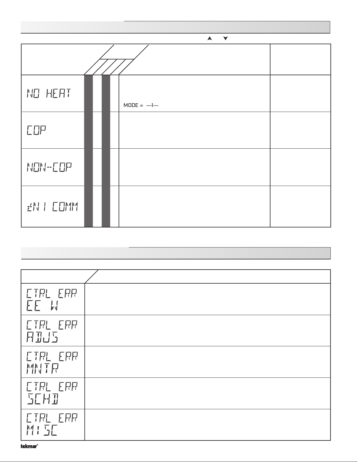
362 Monitor Menu (3 of 3)
MODE = 1 & 2
Note
: To clear the recorded Information in the specific item field, press and hold and .
Access
Level
DescriptionItem Field
Range
LTD
USER
ADV
INST
This item is an adjustable warning. If either the boiler or mixing
supply temperature does not begin to increase within the set
amount of time when required, the control will display a warning
•
message.
MODE = —1—
The number of times that the microprocessor in the control has
reset since this item was last cleared. The control will reset
itself if it has experienced some form of interference that has
disrupted its operation. This can be used to give an indication
•
of the quality of the electrical environment that the control has
been installed in.
The number of times that the control has been powered up
since this item was last cleared. This number will increase if
there is a lowering of the input voltage beyond the control’s
•
usable range. This item can be used as an indication of the
quality of the power source.
The number of times that a communication error has been
detected between the control and either an RTU, RDM or
Remote Start / Stop Module since this item was last cleared.
If the wires between the control and the tekmar Net
•
device are run in a noisy electrical environment, this can cause
interference in the communication between the control and the
tN1/tN2 device.
TM
(tN1/tN2)
3 to 40 min, OFF
default = OFF
0 - 255
0 - 255
0 - 255
362 Error Messages (1 of 4)
Error Displayed Description of Error
The control was unable to store a piece of information into its EEPROM. This error can be caused by
a noisy power source. The control will display the error message and will continue to operate as normal.
Pressing either the Menu or Item button will clear this error.
The control was unable to read a piece of information stored in the Adjust menu. Because of this, the
control was required to load the factory settings into all of the items in the Adjust menu. The control
will stop operation until all of the items available in the Adjust menu of the control have been checked
by the user or installer.
The control was unable to read a piece of information stored in the Monitor menu. Because of this,
the control was required to load the factory settings into all of the items in the Monitor menu. The
control will continue to display the error message until all of the items available in the Monitor menu
of the control have been checked by the user or installer.
clear the error.
The control was unable to read a piece of information stored in the Schedule menu. Because of this,
the control was required to load the factory settings into all of the items in the Schedule menu. The
control will continue to display the error message until all of the items available in the Schedule menu
of the control have been checked by the user or installer.
clear the error.
The control was unable to read a piece of information stored in the Miscellaneous menu. Because of
this, the control was required to load the factory settings into all of the items in the Miscellaneous
menu. The control will continue to display the error message until all of the items available in the
Miscellaneous menu of the control have been checked by the user or installer.
be ADV in order to clear the error.
Note
: Access level must be ADV in order to clear the error.
Note
Note
: Access level must be ADV in order to
: Access level must be ADV in order to
Note
: Access level must
Copyright © D 362 -12/08
32 of 36
Page 33
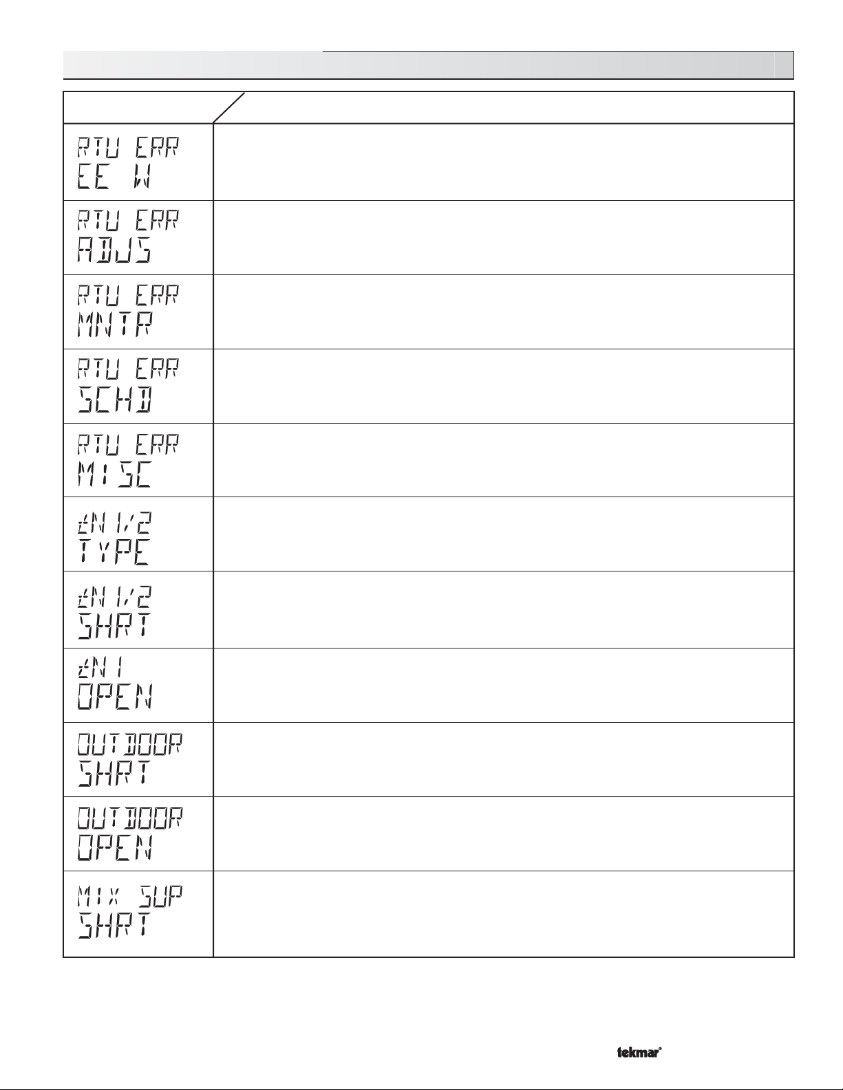
362 Error Messages (2 of 4)
The RTU was unable to store a piece of information to the EEPROM. This error can be caused by a
noisy power source to the control. The control will display the error message and will continue to
operate as normal. To clear this error, press either the Menu or Item buttons.
The RTU was unable to read a piece of information stored in the Adjust menu. Because of this, the
control was required to load the factory settings into all of the items in the Adjust menu. The control
will operate based on only the
in the Adjust menu of the RTU have been checked by the user or installer.
be ADV in order to clear the error.
The RTU was unable to read a piece of information stored in the Monitor menu. Because of this, the
control was required to load the factory settings into all of the items in the Monitor menu. The control
will continue to display the error message until all of the items available in the Monitor menu of the
RTU have been checked by the user or installer.
the error.
The RTU was unable to read a piece of information stored in the Schedule menu. Because of this,
the control was required to load the factory settings into all of the items in the Schedule menu. The
control will continue to display the error message until all of the items available in the Schedule menu
of the RTU have been checked by the user or installer.
clear the error.
The RTU was unable to read a piece of information stored in the Miscellaneous menu. Because of
this, the control was required to load the factory settings into all of the items in the Miscellaneous
menu. The control will continue to display the error message until all of the items available in the
Miscellaneous menu of the RTU have been checked by the user or installer.
be ADV in order to clear the error.
An incorrect device has been connected to the tekmar Net
been connected to the control and either the
Reset Ratio
Menu or Item button to clear the error message from the control.
or the control is in MODE —2—. Once the problem has been corrected, press either the
Characterized Heating Curve
Note:
Access level must be ADV in order to clear
Note:
Heating Curve/Reset Ratio
rorrE fo noitpircseDdeyalpsiD rorrE
settings until all of the items available
Access level must be ADV in order to
TM
tN1/tN2 input terminal. An RTU has
Note:
Access level must
Note:
Access level must
DIP switch has been set to
A short circuit has been read between the tN1/tN2 terminal and a Com terminal on the control. Either
the wires leading to the tN1/tN2 device are shorted or the polarity of the wires is reversed. Determine
the cause and remove the short. To clear this error, press either the Menu or Item buttons.
The control is no longer able to read the information that is coming from the RTU. Reconnect the RTU
and press either the Menu or Item button to clear the error. If the RTU has been deliberately disconnected
from the control, remove power from the control for 10 seconds and then re-power the control in order
to clear the error message.
The control is no longer able to read the Outdoor sensor due to a short circuit. In this case the control
assumes an outdoor temperature of 32˚F (0˚C) and continues operation. Locate and repair the problem
as described in the Data Brochure D070. To clear the error message from the control after the sensor
has been repaired, press either the Menu or Item button.
The control is no longer able to read the Outdoor sensor due to an open circuit. In this case the control
assumes an outdoor temperature of 32˚F (0˚C) and continues operation. Locate and repair the problem
as described in the Data Brochure D070. To clear the error message from the control after the sensor
has been repaired, press either the Menu or Item button.
The control is no longer able to read the Mixing Supply sensor due to a short circuit. In this case, if
the Boil SENS item is set to SUP, the control will operate the mixing device at a fixed 15% of output
as long as there is a Mixing Demand. If the Boil SENS item is set to RET or NONE, the control operates
the mixing device at a fixed 30% of output as long as there is a mixing demand. Locate and repair the
problem as described in the Data Brochure D070. To clear the error message from the control after
the sensor has been repaired, press either the Menu or Item button.
33 of 36
Copyright © D 362 -12/08
Page 34
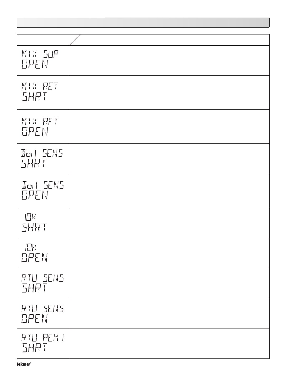
362 Error Messages (3 of 4)
Error Displayed Description of Error
The control is no longer able to read the Mixing Supply sensor due to an open circuit. In this case, if
the Boil SENS item is set to SUP, the control will operate the mixing device at a fixed 15% of output
as long as there is a Mixing Demand. If the Boil SENS item is set to RET or NONE, the control operates
the mixing device at a fixed 30% of output as song as there is a Mixing Demand. Locate and repair
the problem as described in the Data Brochure D 070. To clear the error message from the control
after the sensor has been repaired, press either the Menu or Item button.
The control is no longer able to read the Mix Return sensor due to an short circuit. If the MIXING item
is set to FLOT, the control will operate without ∆T protection of the slab. If the MIXING item is set to
VAR, the control operates the snow melting system as required. In order to provide ∆T protection,
the control periodically shuts off the injection pump and uses the Mix Supply sensor to determine the
Mix Return temperature. Locate and repair the problem as described in the Data Brochure D 070. To
clear the error message from the control after the sensor has been repaired, press either the Menu
or Item button.
The control is no longer able to read the Mix Return sensor due to an open circuit. If the MIXING item
is set to FLOT, the control will operate without ∆T protection of the slab. If the MIXING item is set to
VAR, the control operates the snow melting system as required. In order to provide ∆T protection,
the control periodically shuts off the injection pump and uses the Mix Supply sensor to determine the
Mix Return temperature. Locate and repair the problem as described in the Data Brochure D 070. If
the Mix Return sensor was deliberately not installed, set the MAX ∆T item to OFF. To clear the error
message from the control after the sensor has been repaired, press either the Menu or Item button.
The control is no longer able to read the Boiler sensor due to an short circuit. If the Boiler Minimum
setting is higher than 100°F (38°C) the control closes the boiler contact when the mixing device starts
to operate. The boiler temperature is limited by the operating aquastat. If the Boiler Minimum setting
is lower than 100°F (38°C) the control does not operate the boiler contact. Locate and repair the
problem as described in the Data Brochure D070. To clear the control after the sensor has been
repaired, press either the Menu or Item button.
The control is no longer able to read the boiler sensor due to an open circuit. If the Boiler Minimum
setting is higher than 100°F (38°C) the control closes the boiler contact when the mixing device starts
to operate. The boiler temperature is limited by the operating aquastat. If the Boiler Minimum setting
is lower than 100°F (38°C) the control does not operate the boiler contact. Locate and repair the
problem as described in the Data Brochure D 070. If the Boiler Sensor was deliberately not installed,
set the Boil SENS item to NONE. To clear the control after the sensor has been repaired, press either
the Menu or Item button.
The control is no longer able to read the 10K input because of a short circuit. The control will continue
to operate as if there was nothing connected to the 10K input. Locate and repair the problem as
described in the Data Brochure D 070. To clear the error message from the control after the sensor
has been repaired, press either the Menu or Item button.
The control is no longer able to read the 10K input because of an open circuit. The control will continue
to operate as if there was nothing connected to the 10K input. Locate and repair the problem as
described in the Data Brochure D 070. If a 10K sensor was deliberately not installed, set the 10K item
to NONE. To clear the error message from the control after the sensor has been repaired, press either
the Menu or Item button. 10K ≠ NONE
The air sensor in the RTU is being read as a short circuit. The RTU will continue operation using all
remaining sensors. If all of the sensors are unavailable, the control will continue to operate as if the
RTU was not connected to the control. This error message can be cleared once the sensor has been
repaired. To clear the error message from the control, press either the Menu or Item button.
The air sensor in the RTU is being read as an open circuit. The RTU will continue operation using all
remaining sensors. If all of the sensors are unavailable, the control will continue to operate as if the
RTU was not connected to the control. This error message can be cleared once the sensor has been
repaired. To clear the error message from the control, press either the Menu or Item button.
Copyright © D 362 -12/08
The Remote Sensor 1 attached to the RTU is being read as a short circuit. The RTU will continue
operation using all remaining sensors. If all of the sensors are unavailable, the control will continue to
operate as if the RTU was not connected to the control. This error message can be cleared once the
sensor has been repaired. Locate and repair the problem as described in the Data Brochure D 070.
To clear the error message from the control, press either the Menu or Item button. REM 1 ≠ NONE.
34 of 36
Page 35
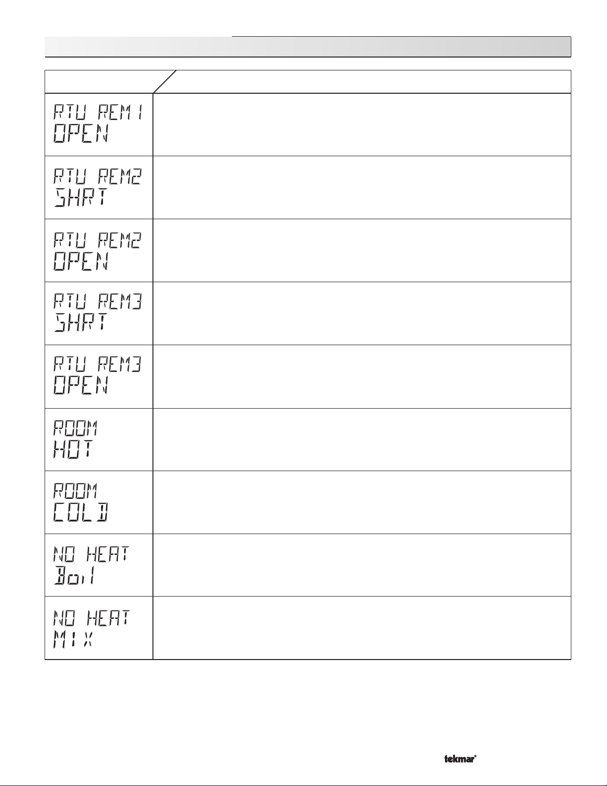
362 Error Messages (4 of 4)
Error Displayed Description of Error
The Remote Sensor 1 attached to the RTU is being read as an open circuit. The RTU will continue
operation using all remaining sensors. If all of the sensors are unavailable, the control will continue
to operate as if the RTU was not connected to the control. This error message can be cleared once
the sensor has been repaired. Locate and repair the problem as described in the Data Brochure D 070.
To clear the error message from the control, press either the Menu or Item button. REMOTE 1 ≠ NONE
The Remote Sensor 2 attached to the RTU is being read as a short circuit. The RTU will continue
operation using all remaining sensors. If all of the sensors are unavailable, the control will continue
to operate as if the RTU was not connected to the control. This error message can be cleared once
the sensor has been repaired. Locate and repair the problem as described in the Data Brochure D 070.
To clear the error message from the control, press either the Menu or Item button. REMOTE 2 ≠ NONE
The Remote Sensor 2 attached to the RTU is being read as an open circuit. The RTU will continue
operation using all remaining sensors. If all of the sensors are unavailable, the control will continue
to operate as if the RTU was not connected to the control. This error message can be cleared once
the sensor has been repaired. Locate and repair the problem as described in the Data Brochure D 070.
To clear the error message from the control, press either the Menu or Item button. REMOTE 2 ≠ NONE
The Remote Sensor 3 attached to the RTU is being read as a short circuit. The RTU will continue
operation using all remaining sensors. If all of the sensors are unavailable, the control will continue
to operate as if the RTU was not connected to the control. This error message can be cleared once
the sensor has been repaired. Locate and repair the problem as described in the Data Brochure D 070.
To clear the error message from the control, press either the Menu or Item button. REMOTE 3 ≠ NONE
The Remote Sensor 3 attached to the RTU is being read as an open circuit. The RTU will continue
operation using all remaining sensors. If all of the sensors are unavailable, the control will continue
to operate as if the RTU was not connected to the control. This error message can be cleared once
the sensor has been repaired. Locate and repair the problem as described in the Data Brochure D 070.
To clear the error message from the control, press either the Menu or Item button. REMOTE 3 ≠ NONE
This warning message will be displayed if the air temperature sensed by an indoor air sensor exceeds
the setting of the ROOM HOT item in the Monitor menu. The control will continue to operate as normal
with this warning. To clear this warning, press either the Menu or Item button.
This warning message will be displayed if the air temperature sensed by an indoor air sensor is below
the setting of the ROOM CLD item in the Monitor menu. The control will continue to operate as normal
with this warning. To clear this warning, press either the Menu or Item button.
This warning message will be displayed if the boiler supply does not increase to the target temperature
within a set time. The time limit is set using the NO HEAT item in the Monitor menu. To clear this
warning, press either the Menu or Item button.
This warning message will be displayed if the mixing device operates continuously at full output for
a set time limit. The time limit is set using the NO HEAT item in the Monitor menu. To clear this warning,
press either the Menu or Item button.
35 of 36
Copyright © D 362 -12/08
Page 36
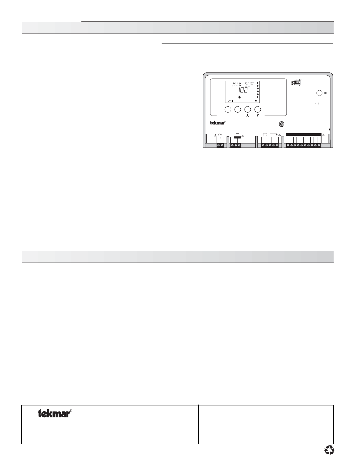
Technical Data
Mixing Control 362
Floating Action / Variable Speed
Literature — D 362, A 362’s, D 001, D 070, E 003, E 021, U 362.
Control — Microprocessor PID control; This is not a safety (limit) control.
Packaged weight — 3.7 lb. (1690 g), Enclosure A, blue PVC plastic
Dimensions — 6-5/8” H x 7-9/16” W x 2-13/16” D (170 x 193 x 72 mm)
Approvals — CSA C US, CSA/UL 61010-1, meets Class B: ICES & FCC Part 15
Ambient conditions — Indoor use only, 36 to 104°F (2 to 40°C)
RH ≤80% to 88°F (31°C), down to 50% above 88°F (31°C)
Altitude <6560 ft (2000 m)
Installation Category II, Pollution Degree 2
Power supply — 115 V (ac) ±10%, 60 Hz, 900 VA
Relays — 230 V (ac) 7.5 A 1/3 hp, pilot duty 240 VA
Var. Pump — 230 V (ac) 2.4 A 1/6 hp, fuse T2.5 A 250 V
Demands — 20 to 260 V (ac) 2 VA
Sensors included — NTC thermistor, 10 kΩ @ 77°F (25°C ±0.2°C) ß=3892
Outdoor Sensor 070 and 2 of Universal Sensor 071.
Optional devices — tekmar type #: 032, 040, 062, 063, 070, 071, 072, 073,
076, 077, 084, 092.
View
Open
1
Item
Menu
Mixing Control 362
Floating Action / Variable Speed
5
4
3
21
Mix
Power
Demand
Mix
Pmp
N L
Mix Demand
WWSD
F
°
Minimum
Maximum
Occ
1
Melting
Idling
7
6810
Pwr
Boiler
Mix
9
Opn Cls/
R
C US
11 1 2
Com
Var
Setback
Reset Ratio
Characterized
None
Heating Curve
Heating
Do not apply power
13
14
15
Com
tN1/
10K16UnO
tN2
Test
off
red
red
For maximum heat,
press and hold
button for 3 seconds.
Meets Class B:
Canadian ICES
FCC Part 15
17
18
Com
Mix19Boil20Out
Sw
Operating Modes
1
2 Snow melting
See product literature
INSTALLATION CATEGORY II
Made in Canada by
tekmar Control Systems Ltd.
tektra 929-04
Power 115 V ±10% 60 Hz 900 VA
Relays 230 V (ac) 7.5 A 1/3 hp, pilot duty 240 VA
Var. Pump 230 V (ac) 2.4 A 1/6 hp, fuse T2.5 A 250V
Demands 20 to 260 V (ac) 2 VA
Signal wiring must be rated at least 300 V.
Wiring must be rated 194°F (90°C) minimum
Mix
Ret
not testing
testing
testing paused
Test
H1176D
The installer must ensure that this control and its wiring are isolated and/or shielded from strong sources of electromagnetic noise.
Conversely, this Class B digital apparatus complies with Part 15 of the FCC Rules and meets all requirements of the Canadian
Interference-Causing Equipment Regulations. However, if this control does cause harmful interference to radio or television reception,
which is determined by turning the control off and on, the user is encouraged to try to correct the interference by reorienting or relocating
the receiving antenna, relocating the receiver with respect to this control, and/or connecting the control to a different circuit from that
to which the receiver is connected.
Cet appareil numérique de la classe B respecte toutes les exigences du Règlement sur le matériel brouilleur du Canada.
Date Code
Caution The nonmetallic enclosure does not provide grounding between conduit connections. Use grounding type bushings and jumper
wires.
Attention Un boîtier nonmétallique n’assure pas la continuité électrique des conduits. Utiliser des manchons ou des fils de accord
spécialement conçus pour la mise á la terre.
Limited Warranty and Product Return Procedure
Limited Warranty The liability of tekmar Control Systems Ltd. and tekmar
Control Systems, Inc. (“tekmar”) under this warranty is limited. The purchaser,
by taking receipt of the tekmar product (“product”), acknowledges receipt of
the terms of the warranty and acknowledges that it has read and
understands same.
tekmar warrants each tekmar product against defects in workmanship and materials, if the product is installed and used in compliance with tekmar's instructions. The
warranty period is for a period of twenty-four (24) months from the production date
if the product is not installed during that period, or twelve (12) months from the
documented date of installation if installed within twenty-four (24) months from the
production date.
The liability of tekmar under this warranty shall be limited to, at tekmar's sole discretion: the cost of parts and labor provided by tekmar to repair defects in materials
and/or workmanship of the defective product; or to the exchange of the defective
product for a replacement product; or to the granting of credit limited to the original
cost of the defective product, and such repair, exchange or credit shall be the sole
remedy available from tekmar, and, without limiting the foregoing in any way,
tekmar is not responsible, in contract, tort or strict product liability, for any
other losses, costs, expenses, inconveniences, or damages, whether direct, indirect, special, secondary, incidental or consequential, arising from ownership or use
of the product, or from defects in workmanship or materials, including any liability
for fundamental breach of contract.
This warranty applies only to those products returned to tekmar during the
warranty period. This warranty does not cover the cost of the parts or labor
to remove or transport the defective product, or to reinstall the repaired or
replacement product. Returned products that are not defective are not covered by this warranty.
This warranty does not apply if the product has been damaged by negligence
by persons other than tekmar, accident, fire, Act of God, abuse or misuse; or
has been damaged by modifications, alterations or attachments made subsequent to purchase which have not been authorized by tekmar; or if the
product was not installed in compliance with tekmar’s instructions and the
local codes and ordinances; or if due to defective installation of the product;
or if the product was not used in compliance with tekmar’s instructions.
This warranty is in lieu of all other warranties, express or implied, which the
Governing Law (being the law of British Columbia) allows parties to contractually exclude, including, without limitation, warranties of merchantability,
fitness for a particular purpose, durability or description of the product, its
non-infringement of any relevant patents or trademarks, and its compliance
with or non-violation of any applicable environmental, health or safety legislation; the term of any other warranty not hereby contractually excluded is
limited such that it shall not extend beyond twenty-four (24) months from the
production date, to the extent that such limitation is allowed by the Governing Law.
Product Return Procedure Products that are believed to have defects in work-
manship or materials must be returned, together with a written description of the
defect, to the tekmar representative for that territory. If the address of the representative is not known, please request it from tekmar at the telephone number
listed below
.
tekmar Control Systems Ltd., Canada
Control Systems
tekmar Control Systems, Inc., U.S.A.
Head Office: 5100 Silver Star Road
Vernon, B.C. Canada V1B 3K4
Tel. (250) 545-7749 Fax. (250) 545-0650
Web Site: www.tekmarcontrols.com
Product design, software and literature are Copyright © 2008 by:
tekmar Control Systems Ltd. and tekmar Control Systems, Inc.
36 of 36
All specifications are subject to change without notice.
Printed in Canada. D 362 -12/08.
 Loading...