

Page 1

TASCAM
MMP-16 Version 4.0
TEAC Professional Division
MMP-16
Modular Multitrack Player
OWNER’S MANUAL
Page 2

Page 3

MMP-16 TASCAM MMP-16 Owner’s Manual • Table of Contents
5
Page 4

6
TASCAM MMP-16 Owner’s Manual
Chapter 1 General Information........................................................................13
MMP-16 Introduction .....................................................................................................................13
Hardware Overview ........................................................................................................................14
Internal Boards for Units with Serial Numbers up to 01344...........................................................................14
Internal Boards for Units with Serial Numbers of 01345 and above ............................................................... 14
Front Panel .................................................................................................................................................. 15
Rear Panel ................................................................................................................................................... 15
Accessory Products......................................................................................................................................16
ViewNet Audio.............................................................................................................................17
Functional Overview........................................................................................................................18
System Specifications.......................................................................................................................21
Chapter 2 Installation........................................................................................23
MMP-16 Materials Kit Box.............................................................................................................23
General Guidelines ..........................................................................................................................24
Mounting Rack Ears ....................................................................................................................................24
Installing Multiple MMP Units.......................................................................................................25
Multiple MMR-8 Rack Installation............................................................................................................... 25
AC Mains and Grounding (Earthing) Considerations....................................................................................26
Audio Cables ....................................................................................................................................26
MMP-16 Back Panel Connections...................................................................................................27
MMP-16 Back Panel Connections for Serial # 01345 and above ...................................................28
Audio Connections ......................................................................................................................................29
Analog Output Connections.....................................................................................................................29
Digital Output Connections ...................................................................................................................... 29
Monitoring Connections...........................................................................................................................29
Timecode and Video Reference Signals........................................................................................................ 30
Video In/Out............................................................................................................................................30
SMPTE/EBU Time Code In/Out..............................................................................................................30
Biphase Connections................................................................................................................................31
Digital Audio Sample Reference Connections ..............................................................................................31
Word Clock.............................................................................................................................................31
AES/EBU Sample Rate............................................................................................................................ 31
MIDI Connections .......................................................................................................................................32
External Controllers & Bus Connections ......................................................................................................32
Lynx Bus / KCU Connection ...................................................................................................................32
MMR Sync Bus Connections...................................................................................................................32
Serial Transport Connection..................................................................................................................... 33
Serial Editor Connection..........................................................................................................................33
Parallel Transport ....................................................................................................................................33
Parallel Tracks.........................................................................................................................................33
Connecting External SCSI Media...................................................................................................34
SCSI Cables .....................................................................................................................................34
Cable Quality ............................................................................................................................................... 34
Cable Length and Device Support ................................................................................................................ 34
Cabling Wide and Narrow Devices in a System............................................................................................35
TASCAM MMP-16 Owner’s Manual • Table of Contents MMP-16
Page 5

7
SCSI Termination ............................................................................................................................35
Kingston Frame Configuration.......................................................................................................35
Wide SCSI Cards and Kingston Frames.........................................................................................36
Removing the Narrow Host Adapter (Symbios SYM 8600SP)......................................................................36
Installing the Wide Host Adapter (Symbios SYM8751SP)............................................................................36
Wide Kingston Drive Frames.......................................................................................................................37
Approved SCSI Drives ....................................................................................................................37
DVD RAM Support.........................................................................................................................38
LIMDOW Optical Drives................................................................................................................38
Remote Controllers for the TASCAM MMP-16.............................................................................39
Keyboard Operation (with MM-RC option)...................................................................................39
Using the PC Keyboard................................................................................................................................ 40
Powering Up the System..................................................................................................................41
Verifying MMP-16 Installation.......................................................................................................41
Software Updates ......................................................................................................................................... 42
Factory Default Settings..................................................................................................................43
Chapter 3 MMP-16 Keys and Status Displays.................................................44
MMP-16 Keys & Definitions...........................................................................................................44
MMP-16 Front Panel .......................................................................................................................46
Front Panel Indicators, Switches, and Displays..............................................................................48
LED Indicators ............................................................................................................................................48
Configuration Settings ............................................................................................................................. 48
Active Mode/Key Indicators ....................................................................................................................48
Track Status and Metering .......................................................................................................................48
Meter LEDs ............................................................................................................................................. 49
Machine Status LEDs ..............................................................................................................................49
Liquid Crystal Display (LCD)......................................................................................................................50
Normal State Display...............................................................................................................................50
Setup State Display..................................................................................................................................51
View Track State Display.........................................................................................................................51
Slip Track State Display...........................................................................................................................52
Load Track State Display.........................................................................................................................52
Backup State Display...............................................................................................................................53
Verify State Display.................................................................................................................................54
Error State Display...................................................................................................................................54
Front Panel Key Groups..................................................................................................................55
Transport Group...........................................................................................................................................55
Setup and Wheel Group ...............................................................................................................................56
Wheel..........................................................................................................................................................57
Track Group ................................................................................................................................................58
Keypad Group .............................................................................................................................................62
Chapter 4 MMP-16 Operation...........................................................................68
Loading and Mounting Drives ........................................................................................................68
Loading a Project.............................................................................................................................69
Loading Individual Tracks..............................................................................................................69
Viewing Tracks............................................................................................................................................70
MMP-16 TASCAM MMP-16 Owner’s Manual • Table of Contents
Page 6

8
Unloading Tracks.........................................................................................................................................70
Deleting Tracks from the Disk......................................................................................................................70
Using the Backup Functions............................................................................................................70
Backup ........................................................................................................................................................71
Rename .......................................................................................................................................................71
TapeMode Convert ...................................................................................................................................... 72
Export..........................................................................................................................................................72
WaveFrame Export..................................................................................................................................72
OMF Export............................................................................................................................................73
To Import the OMF Export File into Pro Tools.............................................................................................73
Crossfades in OMF......................................................................................................................................73
Tape Mode Export to OMF......................................................................................................................74
Pro Tools Export......................................................................................................................................74
Export As ....................................................................................................................................................74
Dynamic Backup Status Display...................................................................................................................75
Using Registers ................................................................................................................................75
Recalling Registers ...................................................................................................................................... 75
Capturing the Current Time Code ................................................................................................................. 75
Trimming Time Code Values.......................................................................................................................76
Using the Entry Register .............................................................................................................................. 76
Editing..............................................................................................................................................77
Local & Studio Monitoring .............................................................................................................82
Headphone Volume (LEVEL)......................................................................................................................82
Headphone Jack (PHONES).........................................................................................................................82
The Lynx Bus...................................................................................................................................82
Transport Control.........................................................................................................................................83
Track Record Arm/Select (MMR-8 Only).....................................................................................................83
Head/Tail.....................................................................................................................................................83
Slip Track/Region........................................................................................................................................ 83
Prev/Next.....................................................................................................................................................83
Undo/Redo...................................................................................................................................................83
Clear/Paste...................................................................................................................................................84
The MMR Bus .................................................................................................................................85
Chapter 5 MMP-16 Setup Menus .....................................................................86
The Setup State & the Setup Menus ...............................................................................................86
Setup Operation ...............................................................................................................................87
Setup Menu Chart...........................................................................................................................88
000 Basic Setup................................................................................................................................92
000 Control Mode........................................................................................................................................92
Local/Bus................................................................................................................................................92
Time Code Chase.....................................................................................................................................92
Biphase Chase ......................................................................................................................................... 92
Serial Transport.......................................................................................................................................93
Editor......................................................................................................................................................93
Varispeed ................................................................................................................................................93
Serial Editor Port Details..............................................................................................................................93
Record Ready Tallies...............................................................................................................................93
Sony P2 Chase and Offset Commands...................................................................................................... 93
Serial Editor Port Active When Not ONLINE ..........................................................................................93
Automatic ONLINE.................................................................................................................................93
Local Machine Response to Serial Record Commands..............................................................................93
TASCAM MMP-16 Owner’s Manual • Table of Contents MMP-16
Page 7

9
Program Speed Play.................................................................................................................................94
Editor Mode Operation Without Video Reference.....................................................................................94
Hybrid Protocol on Serial Editor Port.......................................................................................................94
001 Frame Reference ...................................................................................................................................94
Automatic................................................................................................................................................ 94
Video.......................................................................................................................................................94
002 Sample Reference..................................................................................................................................94
Automatic................................................................................................................................................ 94
AES/EBU Input.......................................................................................................................................94
Ext Wordclock......................................................................................................................................... 95
003 Timecode Type......................................................................................................................................95
004 Sample Rate.......................................................................................................................................... 95
006 Varispeed Rate...................................................................................................................................... 95
100 Bus Control ...............................................................................................................................96
100 Sync Group........................................................................................................................................... 96
110 MMR Bus Request................................................................................................................................96
111 Ident Request ........................................................................................................................................96
112 Ident Assigned ......................................................................................................................................96
120 Lynx Bus ..............................................................................................................................................96
121 Lynx Bus Address.................................................................................................................................96
122 Lynx Bus V500 Mode ...........................................................................................................................96
200 Transport ..................................................................................................................................97
210 Loop Mode............................................................................................................................................97
211 Loop Record .........................................................................................................................................97
212 Pre-roll..................................................................................................................................................97
213 Post-roll................................................................................................................................................97
220 Next / Previous Mode............................................................................................................................ 97
221 Edit Sync Mode..................................................................................................................................... 97
250 Slip Commit.......................................................................................................................................... 98
300 Biphase......................................................................................................................................98
300 Biphase Frame Rate...............................................................................................................................98
301 Biphase Pulse Rate................................................................................................................................ 98
302 Biphase Input........................................................................................................................................98
400 Remote.......................................................................................................................................98
400 Editor Device ........................................................................................................................................ 98
TASCAM MMR-8...................................................................................................................................99
Sony PCM-7030......................................................................................................................................99
Sony BVU-950........................................................................................................................................99
404 Editor Chase..........................................................................................................................................99
420 MIDI Device ID....................................................................................................................................99
500 Audio.........................................................................................................................................99
510 Crossfade..............................................................................................................................................99
520 Meter Reference Level ..........................................................................................................................99
522 Clip LED on Play..................................................................................................................................99
530 Reference Tone.....................................................................................................................................99
550 Remote Meter Source..........................................................................................................................100
600 Digital I/O ...............................................................................................................................100
610 Digital Output Delay ...........................................................................................................................100
700 Disk.......................................................................................................................................... 100
710 Disk Initialize...................................................................................................................................... 100
711 Disk Low Format ................................................................................................................................ 100
720 Disk Cleanup ......................................................................................................................................100
790 Drives Mounted...................................................................................................................................101
800 Tracks/Project......................................................................................................................... 101
MMP-16 TASCAM MMP-16 Owner’s Manual • Table of Contents
Page 8

10
800 Project Name.......................................................................................................................................101
810 Track Prefix ........................................................................................................................................ 101
900 System .....................................................................................................................................101
900 Store Settings......................................................................................................................................101
901 Recall Settings ....................................................................................................................................101
910 Set MM:DD:YY [Date]....................................................................................................................... 101
911 Set HH:MM:SS [Time] .......................................................................................................................102
912 Change Password................................................................................................................................ 102
920 LED Brightness................................................................................................................................... 102
940 Machine Name.................................................................................................................................... 102
950 IP Address...........................................................................................................................................102
Setting the IP Address............................................................................................................................ 102
Format of IP Addresses.......................................................................................................................... 102
951 IP Net Mask........................................................................................................................................102
952 IP Gateway.......................................................................................................................................... 102
Important Rules for IP Addresses ............................................................................................................... 103
980 Serial Number..................................................................................................................................... 103
990 Software Version.................................................................................................................................103
995 Load Software..................................................................................................................................... 103
Chapter 6 File Format Support........................................................................105
Show Project Format ..................................................................................................................... 105
Show Track Format, Drive ID ......................................................................................................105
Formatting Macintosh Disks.........................................................................................................105
Delete and Disk Cleanup for Macintosh Volumes........................................................................ 106
Macintosh File System Errors.......................................................................................................106
Macintosh Files Created by the MMR ........................................................................................................106
Support for Pro Tools® Session Files ...........................................................................................107
Pro Tools Features Supported..................................................................................................................... 108
Pro Tools Features Not Supported..............................................................................................................108
Dynamic Voice Allocation ..................................................................................................................... 108
TDM Plug-Ins .......................................................................................................................................108
Voice Output Assignments..................................................................................................................... 109
Restrictions When Using the Pro Tools Session Format.............................................................................. 109
Pull Up / Pull Down ............................................................................................................................... 109
Frame and Sample Rates in Tape Mode..................................................................................................109
Limitations on Number of Tracks ........................................................................................................... 109
Session Start Time Restrictions.............................................................................................................. 109
Using TapeMode with ProTools Sessions ............................................................................................... 110
Pro Tools Volume and Mute Automation.....................................................................................111
Volume Automation...................................................................................................................................111
Mute Automation ....................................................................................................................................... 111
Disabling Pro Tools Volume Automation...................................................................................................112
Audio File Time Stamp Support ...................................................................................................112
AIFF File Support .........................................................................................................................113
OMF Files ......................................................................................................................................113
Zaxcom DEVA Broadcast Wave File Support..............................................................................113
DEVA Files Naming Conventions.............................................................................................................. 114
Akai DD-8 Support........................................................................................................................ 114
Playback....................................................................................................................................................114
TASCAM MMP-16 Owner’s Manual • Table of Contents MMP-16
Page 9

11
Export........................................................................................................................................................114
Editing File Formats not Written by The MM Series...................................................................114
Sonic Solutions File Support .........................................................................................................115
Using Sonic Lightspeed .............................................................................................................................115
Sonic SSP, USP, and HD System Support .................................................................................................. 115
Sonic Fade Files......................................................................................................................................... 115
Format Chart ................................................................................................................................. 116
Chapter 7 MMP-16 System Applications.......................................................118
Film Post Production.....................................................................................................................118
Biphase Setup Menus ................................................................................................................................. 119
MMP-16 Film Connections........................................................................................................................ 120
Video Post Production...................................................................................................................120
The Lynx Bus ............................................................................................................................................ 120
Chapter 8 Maintenance & Service..................................................................121
MMP Output Level Calibrations.................................................................................................................121
MOC Calibration Procedure....................................................................................................................... 121
Adding External Drives to the System.......................................................................................... 122
Formatting Disks ...........................................................................................................................123
Using Removable Media................................................................................................................123
Chapter 9 Technical Support..........................................................................124
MMP-16 System Software............................................................................................................. 124
Appendix A: Control Panel Command Summary........................................................................125
Transport Group ....................................................................................................................................125
Setup and Wheel Group......................................................................................................................... 125
Keypad keys.......................................................................................................................................... 126
Track Select Keys..................................................................................................................................128
Appendix B: TASCAM MMP-16 Drive Compatibility Chart..........................129
Approved SCSI Drives ............................................................................................................................... 129
Appendix C: WaveFrame Compatibility......................................................................................131
Appendix D: MMP-16 Cable Information.................................................................................... 133
Parallel Tracks and Parallel Transport Connector Pinout.............................................................................133
MIDI IN/THRU/OUT Connector pinout..................................................................................................... 134
LYNX (Remote Controller) Connector pinout............................................................................................ 134
EDITOR Connector pinout......................................................................................................................... 134
TRANSPORT (Sony 9-pin) Connector pinout............................................................................................ 135
ANALOG OUTPUT Connectors pinouts.................................................................................................... 136
BIPH (Biphase) Connectors pinout............................................................................................................. 136
DO (AES/EBU Digital Audio Out 1-8) Connector pinout ........................................................................... 137
AO (AES/EBU Digital Audio Out 9-16) Connector pinout .........................................................................137
SYNC (MMR-Bus) Connector pinout ........................................................................................................138
TIMECODE IN Connector......................................................................................................................... 138
TIMECODE OUT Connector.....................................................................................................................138
WORD CLOCK IN Connector ................................................................................................................... 139
WORD CLOCK OUT Connector............................................................................................................... 139
VIDEO IN/OUT Connector........................................................................................................................139
SERIAL CONNECTORS ..........................................................................................................................139
SCSI Connector.........................................................................................................................................139
PRX Connector.......................................................................................................................................... 139
MMP-16 TASCAM MMP-16 Owner’s Manual • Table of Contents
Page 10

12
Keyboard Operation (with optional MM-RC) ............................................................................................. 140
The MM-RC Keyboard Connector .............................................................................................................140
Appendix E: MMP-16 Glossary....................................................................................................141
Appendix F: Disk Time Chart ....................................................................................................... 147
Appendix G: Macintosh File System Error Messages..................................................................148
Macintosh File System Error Codes............................................................................................................ 149
Appendix H: MMR/MMP MIDI Machine Control Protocol .......................................................154
MMC Information Fields ...........................................................................................................................154
MMR-8 MMC Signature............................................................................................................................ 155
MMP-16 MMC Signature .......................................................................................................................... 156
MIDI Inquiry Message...............................................................................................................................156
Index ..............................................................................................................................................157
MMP-16 Owner’s Manual Version 4.1 TRAINING
TASCAM MMP-16 Owner’s Manual • Table of Contents MMP-16
Page 11
13
Chapter 1 General Information
This chapter presents the main features and capabilities of the MMP-16 hardware and a functional
overview of its Panel/Display states. MMP-16 product specifications are also included.
MMP-16 Introduction
2
3
CLIP
MAX
+12
+6
-6
-12
-25
SLIP
10
COPY
2 3
PHONES
MMP-16
54 6 7 11
8 9
10
CLIP
11
CLIP
MAX
+12
+6
0
-6
-12
-25
SLIP
CLEAR
MAX
+12
+6
0-60
-12
-25
SLIP
12
PASTE
4
ON
LINE
13
CLIP
MAX
+12
+6
-6
-12
-25
SLIP
INSERT
5
CLIP
MAX
+12
+6
0
-6
-12
-25
SLIP
14
OPEN15UNDO
6
DELETE7UNLOAD
TRACK
UNMOUNT
12
13 14 16
CLIP
MAX
+12
+6
-12
-25
SLIP
VIEWLOAD
TRACK
POWER
IDENT
INT
AES
WORD
MMR
48.000
44.100
P. UP
P. DOWN
NON STD.
+/-
CONTROLREFERENCE
FRAME
MODE
LOCAL/BUS
VIDEO
TC CHASE
TC
BIPH CHASE
BIPH
BIPH TRAN
LYNX
SER TRAN
EXT RSLV
EDITOR
SYNC GRP
VARI
1
2 MMR
LYNX
MAST
3
SLAVE
4
TC/FEET
SUBF
-
+
TRIM
SHTL
REMOVABLE
HARD DRIVE
15
CLIP
MAX
TONE
+12
MIDI
+6
ERROR
0
0
BUSY
-6
-6
LOCK
-12
-25
OFFSET
INTERLOCK
SLIP
16
REDO
8
BACKUP
SLIP
TRACK
MOUNT
CLR
LYNX SYNC
CANCEL
IN
HEAD
NEXT EDIT
7
OUT
OFST4RDR
1 2
8 9
TAIL
5
PREV EDIT
6
FREE
3
TIME
CAPT
0
SAMPLE
TIME CODE
RATE
29.97
NDF
DF
25
24
SHIFT
SETUP
YES
STO
TRIM JOG
=
NO
RCL
LOOP
LOC
TASCAM
1
CLIP
MAX
+12
+6
0 0
-6
-12
-25
SLIP
9
CUT
1
EVENT
EDIT MON
MMP-16 Front View
The MMP-16 is a non-linear digital replacement for the analog or digital tape machines found in
recording studios and broadcast facilities, and for magnetic film dubbers found in film and video postproduction facilities. The MMP-16 can play back sixteen tracks of material from one or more SCSI hard
drives or other removable media. Each MMP-16 can play back from multiple SCSI disk drives of various
types. Playback can be in exact or track-slipped synchronization to industry-standard film, video, and
audio devices, whether they are mechanical tape-based or hard drive-based.
Audio files played back on the MMP-16 may consist of selectable linear 16-bit or linear 24-bit words at
sample rates of 48.0 kHz or 44.1 kHz, modifiable to a pull-up or pull-down rate, including conversion
between PAL, film, and video, making fourteen total discrete sample playback rates. The analog output
section uses balanced +4 dBu analog connections on a DB-25 connector that are pin-compatible with the
TASCAM DA-88 and may use the same cables. The two digital audio output connections are labeled DO16 (output channels 1-8) and AO-16 (output channels 9-16) and conform to the AES/EBU standard for
direct digital recording and playback. Digital audio output is provided on two 25-pin DB-25 connectors
which can use a standard TASCAM DA-88 cable (the analog cable – not TDIF) to provide four stereo
AES outputs per connector. See the Pin out drawing given in Appendix D for detailed information. The
unit can be synchronized to the digital sample clock reference coming in on digital input channels 7&8 of
the AO-16 board (pin 7 is REF IN +, pin 20 is REF IN -, and pin 8 is REF IN GND).
TASCAM MMP-16 Owner’s Manual • Chapter 1 • General Information MMP-16
Page 12

14
The MMP-16 will directly play back material created on many different digital audio workstation
systems. A format compatibility chart is given in the Functional Specifications section of this chapter.
The disk drive or drives containing edited Project (EDL and audio) files may be simply “unplugged” from
the workstation and then “hot-plugged” into the MMP-16, using the standard internal Kingston hard drive
carrier, or otherwise connected to the MMP-16’s external SCSI port. Optionally, files on a RAID may be
accessed via the external SCSI port as well. Once the drive(s) are mounted by the MMP-16, tracks from
one or more projects may be loaded as required for the mix session. Sound files of the same or different
audio file formats may be played back on the same unit simultaneously from one or more drives.
When the MMP-16 is turned on for the first time, the system default operating parameters are loaded, and
the machine boots into the Normal state (see the Functional Overview section in this chapter). There are
ten user settings files that may be stored to and recalled from the internal hard drive so that the MMP-16
setup parameters can be instantly reconfigured between mix sessions. The MMP-16’s operating
parameters can be manually changed at any time via Setup menu selections. Password protection may be
used to prevent some parameters from being changed inadvertently.
Hardware Overview
The MMP-16 comes standard with one removable Kingston drive carrier. The Kingston carrier can hold a
standard SCSI drive for playback of audio tracks. An internal IDE hard drive holds the operating system,
the MMP-16 software, and the parameter settings files. Additional external SCSI drives can be connected
and accessed by the MMP-16. This allows loading tracks simultaneously from more than one disk. A list
of approved media drives is given in Appendix B.
The MMP-16 is based on a standard Intel Pentium™ processor-based PC motherboard, with
integral PCI and ISA bus slots running under an industry-standard operating system. The MMP-16
processing and interface boards plug directly into this PC motherboard. There is a Lithium battery #
CR2032 for the CMOS circuit on the motherboard. Caution: Battery May Explode if Mistreated. Do
Not Recharge, Disassemble, or Dispose of in Fire. The MOC (digital-to-analog Output Converter)
boards are in their own shielded cage, connected to the AO-16 (Analog Output) card via ribbon cables.
Very high quality 20-bit converters on all analog outputs assure excellent audio fidelity. The MMP-16
uses 24-bit internal digital resolution for all digital audio processing. The MMP-16 plays back audio
stored in standard linear 16-bit or 24-bit sound files.
Internal Boards for Units with Serial Numbers up to 01344
The PRX (DSP) card performs the audio processing for the MMP-16. A standard Symbios SCSI-2
controller card also plugs into the PCI bus. The Sync card, the UI/B (User Interface/Biphase) card, the
AO-16 (Analog Output) card, and the DO-16 (AES/EBU Digital Output) card are all plugged into the ISA
bus. The Biphase Operations Board (BOB) occupies a slot on the back panel to provide connections for
the system’s four Biphase inputs and one Biphase throghpu. It is attached to the UI/B card via a ribbon
cable and is not plugged into a slot.
Internal Boards for Units with Serial Numbers of 01345 and above
Units with serial numbers of 01609 and above have a different set of internal processing boards.
Functionally, these units are identical to previous units. The change was made to facilitate a more
streamlined manufacturing process. Instead of separate boards for DSP processing, sync, remote control,
etc., these functions have been combined into a single board designated as the M2 board. Connectors on
the side of the M2 board have ribbon cables attached which break out to brackets and connectors serving
the same functions as the previous array of boards and connectors.
MMP-16 TASCAM MMP-16 Owner’s Manual • Chapter 1 • General Information
Page 13

15
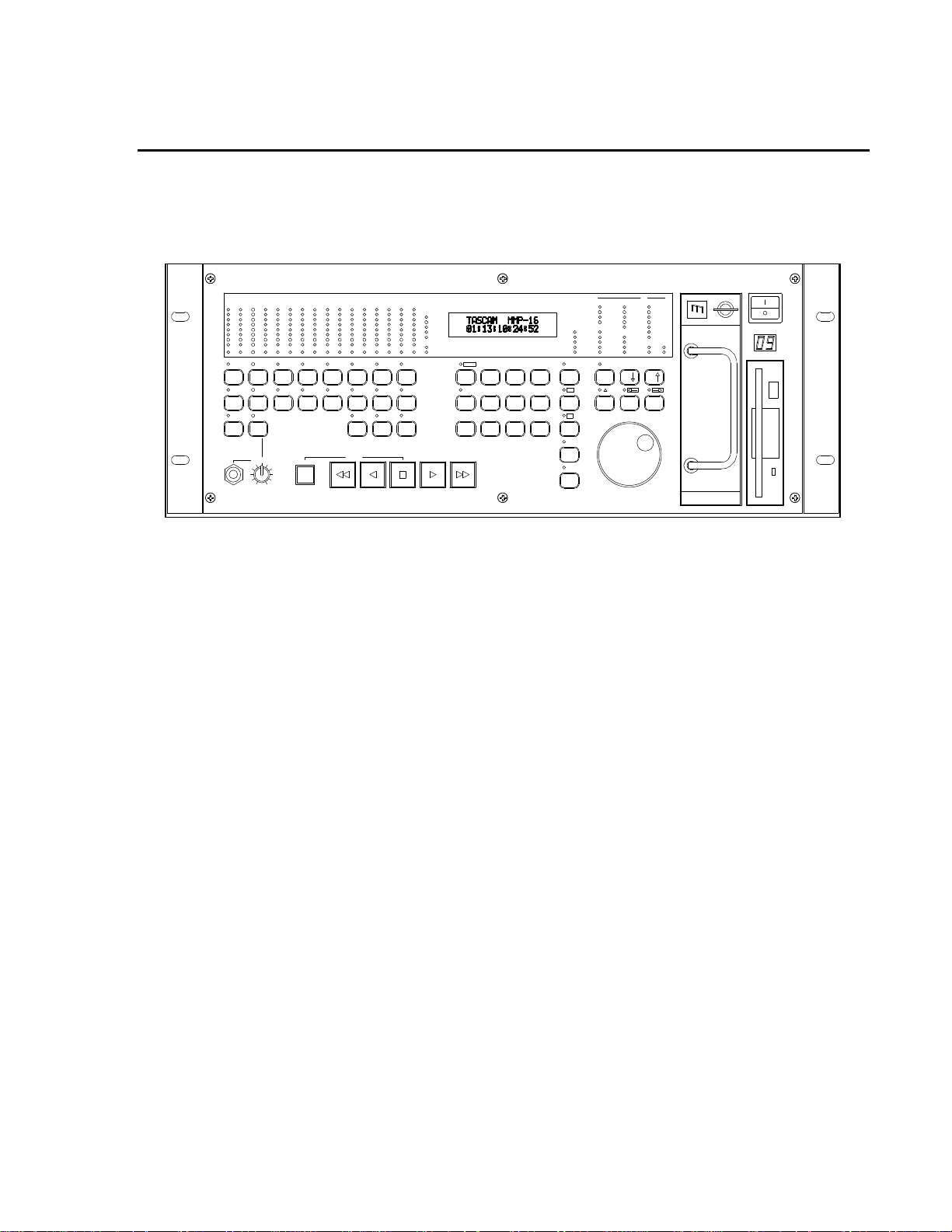
Front Panel
The MMP-16 front panel contains 44 soft-touch keys with most of the common dubber and audio
playback functions available through one or two keystrokes. There are also five large illuminated motion
control buttons (Play, Stop, FF, Rew, Reverse Play) for track playback and “play head” locating, and an
Online button for setting the MMP-16 offline (as a local machine) or online (as a synchronized slave or a
master machine). When the MMP-16 is set as a slave, it can chase SMPTE time code (LTC), biphase
(film tach), a TimeLine Lynx™ module, or another MMP-16 or MMR-8.
A 40-character (two line by 20-character) LCD (Liquid Crystal Display) serves as the MMP-16 status and
control text window. The top line typically shows the machine status and current time code or feet/frames
location, while the bottom line shows various time code registers (In, Out, memory, slip. etc.) and accepts
input from the front panel. The entire display may also alert the operator to any machine or user error
conditions. Text can be scrolled horizontally or vertically, using the Wheel or arrow keys, for entering
Panel/Display state and setup information, or for finding and loading projects and tracks.
There are dedicated front panel LED peak meters that always display monitor level information for the
track outputs during playback. Each meter contains seven green, yellow and red LEDs plus a CLIP/Hold
LED for easy at-a-glance level monitoring. An additional 70 status LEDs instantly identify current
synchronization modes, bus control modes, sample and frame reference settings, and transport status.
Rear Panel
The MMP-16 rear panel contains all the audio and synchronization connections. To minimize connector
footprint, female DB-25 connectors are used for the audio connections. The sixteen analog audio outputs
are divided between two female DB-25 connectors, each providing eight channels of audio. Each analog
connector mounts on a separate card within the chassis, and is labeled to show which channels (1-8 or 9-
16) are present. The connectors are pin-compatible with the TASCAM DA-88 analog audio connector.
The digital output card allows direct digital audio transfers out of the MMP-16. Because it uses standard
AES/EBU digital signal conventions, there are four stereo digital audio outputs with odd-even track pairs
per connector. Tracks 1+2 are on the first AES/EBU connection, tracks 3+4 on the second AES/EBU
connection, and so on. Note that these connectors carry AES/EBU digital signals using the standard DA88 analog audio cable and are NOT pin-compatible with the TASCAM DA-88 TDIF digital audio format
connector cable.
Built-in biphase control allows the MMP-16 to automatically lock to and chase biphase devices
without having to use an external biphase to SMPTE LTC adapter. Up to four biphase input
signals can be simultaneously connected to the MMP-16. The active biphase input is linked to the active
Sync Group assignment and is determined by menu selection (Setup Menu 100). A biphase throughput
connector passes through the selected incoming biphase signal. A biphase throughput connector passes
through the selected incoming biphase signal. Software Setup Menu 300 bank parameters (frame rate,
pulses per frame, input type) allow various biphase devices to be used with the MMR-8. The biphase
connector is not intended for public telecommunications network connection.
Video post-production work can be done with any industry-standard playback device. The MMP-16
supports SMPTE/EBU Linear Time Code, Word Clock, Video sync, MIDI Time Code, MIDI Machine
Control input, and Sony 9-pin serial in and out (P2- protocol).
TASCAM MMP-16 Owner’s Manual • Chapter 1 • General Information MMP-16
Page 14

16
Accessory Products
The TASCAM MM-RC is a dedicated remote control unit designed specially for use with the MMR-8
recorder and the MMP-16 player. It connects directly to the UI/B board on the MMR/MMP back panel
and allows control of any combination of up to 100 MMR-8 or MMP-16 units.
The TASCAM MMU-16 is a multi-segment digital meter unit which can display sixteen channels of
audio level information. Two connectors on the back of the MMU-16 allow it to be connected to one or
two MMR-8 units, or an MMP-16 sixteen channel player. The MMU-16 can also be connected to the
MM-RC for displaying detailed level information for the MMR-8 or MMP-16 unit being accessed by the
MM-RC. The MMU-16 comes with standard rack ears for mounting in a standard 19” equipment rack
and also with mounting brackets for attaching the unit to an MM-RC.
The TimeLine Lynx Keyboard Control Unit (KCU) can function directly as a remote controller for up to
six MMP-16s without the use of dedicated Lynx-2 modules, since the MMP-16 contains the functional
equivalent of an integrated Lynx-2 synchronizer. Optionally, Lynx-2 modules can also be connected to
the Lynx port of the MMP so that other transports connected to the Lynx bus may also be controlled from
a Lynx KCU connected to the MMP-16. TimeLine offers a special software version for the Lynx KCU
(KCU 900 software) which includes special MMP support for some editing and event slip commands.
Other remote controllers can also be used for controlling the transport functions of the MMP-16 through
the Parallel Transport connector or via Sony P2 protocol through the 9-pin serial Editor port.
MMP-16 TASCAM MMP-16 Owner’s Manual • Chapter 1 • General Information
Page 15
17
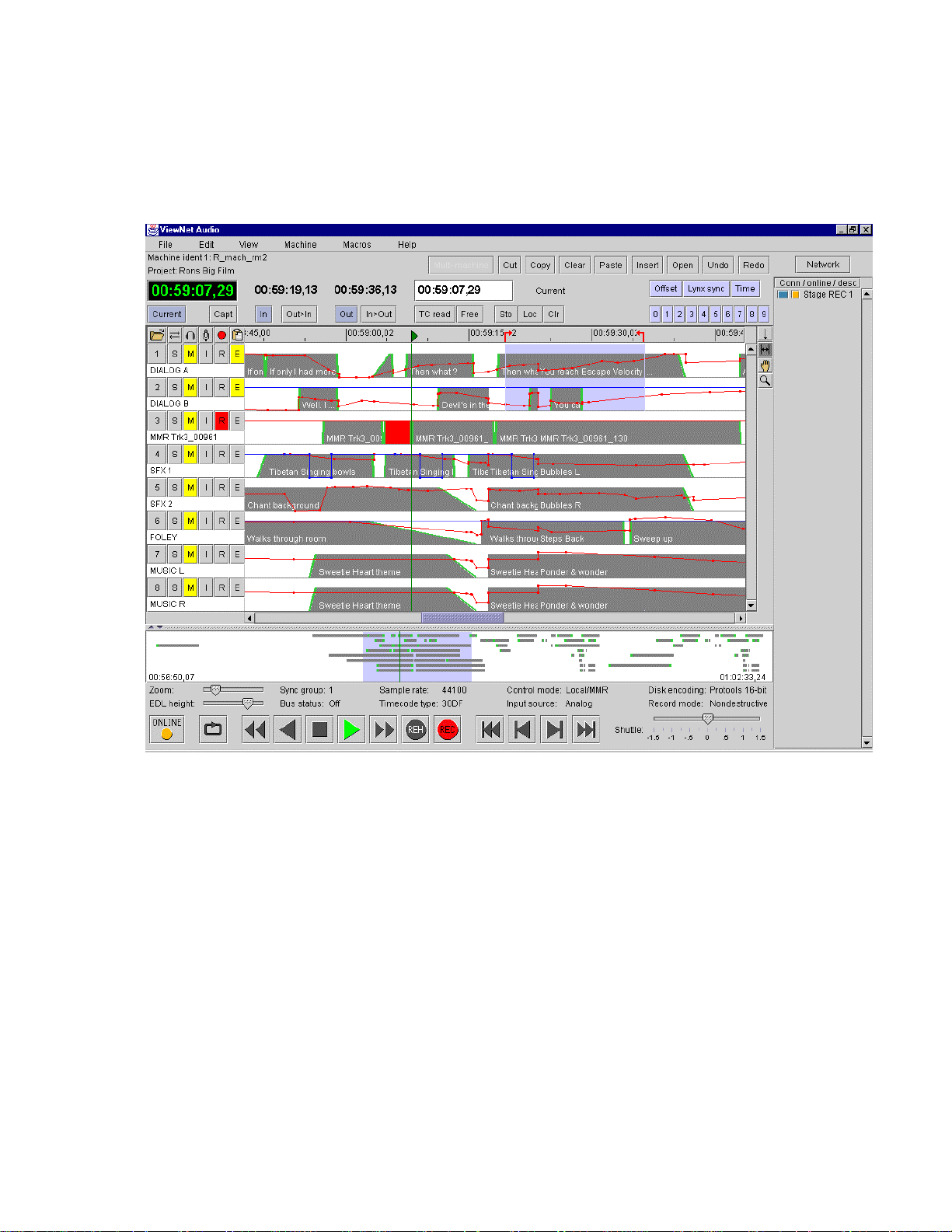
ViewNet Audio
The ViewNet Audio option is a graphical interface network for the MM Series modular multitrack
machines which provides a Fast Ethernet (100 Mbps) connection for the MM unit and the special
ViewNet Audio software application running on a computer attached to the network.
ViewNet Audio Project View Screen
ViewNet Audio is designed to allow system administration and control of setup parameters for all
machines from any computer on the network. Since ViewNet was written using the Java programming
environment, the software application can be run from computers running the Windows (95, 98, or NT),
Macintosh, or UNIX (Linux) operating systems. Administration and Server software is included with the
system to allow for setting levels of security in multi-room facilities. This helps to prevent operators from
accidentally controlling machines in other areas of the facility for which they do not have access
permission.
ViewNet provides a graphical editing environment for making changes to sound events at the mix. Multimachine edits and macros are also supported. Real time scrolling of sound events with clip names
provides a visual cue sheet for mixers. Complete access to all system setup parameters and the ability to
broadcast parameters to multiple sets of machines makes it easy for machine room operators to set up jobs
for different clients in different rooms. ViewNet is available from authorized TASCAM MM series
dealers and distributors.
TASCAM MMP-16 Owner’s Manual • Chapter 1 • General Information MMP-16
Page 16

18
Functional Overview
The MMP-16 operates in any of eight different Panel/Display states (simply referred to as “states” for
convenience). These states are distinguished by the nature of the information displayed in the LCD
window and by which keys are functionally available while in that state. These MMP-16 Panel/Display
states are described here.
Normal state is the default Panel/Display state on power-up. In this state, the LCD shows the current
system play time in the top of the display, and shows the active register (last requested register or function
time) in the bottom of the display. All keys are active while in this state, and will respond by performing
an action, accessing a register, or changing to the state written on the key. Shifted key functions are also
available by first pressing the SHIFT key, then pressing the key which corresponds to the desired shifted
function. Once the SHIFT key is selected, pressing the appropriate key to activate the desired shifted
function completes the SHIFT operation. The SHIFT state can be cancelled by pressing SHIFT again, or
by pressing CLR, to return the system to normal key selection.
Pressing the SETUP key activates the Setup state. This state gives access to the system setup menus,
where most of the operating parameters of the MMP-16 can be altered. Some parameters are changeable
only under certain operating conditions (while stopped, etc.), although all are viewable at any time in the
Setup state. Once in the Setup state, you may return to the Normal state by pressing the SETUP key
again, or by pressing CLR.
There are three types of Panel/Display states that deal with MMP-16 track operations. These are Load
Track, View Track, and Slip Track. Pressing the LOAD TRACK, TRACK, or SLIP keys puts the
MMP-16 into one of these Track states. The SEL keys for each MMP track are used in conjunction with
these keys to identify the specific track to be loaded, viewed, or slipped.
There are also two keys to the left of the Track state keys labeled EDIT and MON. These keys do not
change the state of the MMP display, but are used to determine what status is being indicated for each
MMP track by the track selection LEDs when the SEL keys are pressed while in the Normal state of
operation. One of these keys is always active as the current Track Mode. Since these keys function along
with the Track state keys to identify the function being specified by the SEL keys, the entire group of five
keys (EDIT, MON, LOAD TRACK, TRACK, and SLIP) are also referred to as the Track Mode keys.
The Track states supersede the Normal state since they change the display and make certain keys
unavailable until the Track state is exited or cleared. To exit a Track state and return the MMP-16 to the
Normal state, it is necessary to either complete the selected track operation (by pressing STO to load a
Project, for example), or press the selected Track state key again, or press the CLR key to cancel the
operation. After exiting a Track state, the system will return to the Normal state and the last selected
Track Mode (EDIT, MON).
Pressing the LOAD TRACK key activates the Load Track state. This state allows for loading
WaveFrame projects, OMF Compositions, or Pro Tools Session files from any mounted disk volume.
This state also allows loading of individual tracks from a Project, Composition, or Session (hence the
name of this key and state), and moving of tracks from one MMP channel to another. The shifted function
of LOAD TRACK allows for deleting WaveFrame Projects or Tracks. The MMP-16 software does not
currently allow OMF Compositions and Pro Tools Session Files to be deleted.
MMP-16 TASCAM MMP-16 Owner’s Manual • Chapter 1 • General Information
Page 17

19
The MMP Backup state is accessed via the Load Track state by pressing SHIFT+SLIP after choosing
(scrolling to) the desired Project while in the LOAD TRACK state. This state is similar to the Setup state
in that it has menu choices which are accessed by using the Up/Down arrow keys or the Wheel. The key
choices available in the Backup state are the same as those in the Setup state, hence it exists at the same
level of the hierarchy of panel/display states as the Setup state.
Pressing the TRACK key activates the View Track state. This state allows for viewing the names of
loaded tracks, and unloading of tracks (the shifted function of the TRACK key) from the loaded track list.
Pressing the SLIP key activates the Slip Track state. This state allows for slipping one or more of the
already loaded tracks in time.
Verify state supersedes the Normal and Track states. The two most common Verify state functions are
confirmation (a Yes/No answer is required from the user) and password entry (a password must be
entered to complete the action request). Both of these requests override most other actions or do not allow
access to the Normal, Setup, or Track states until they are cleared or a valid response is entered. Verify
state, when cleared, usually drops the MMP-16 back into the previously active state.
Error state is the final level in the hierarchy of Panel/Display states. In this state, the ERROR status light
flashes and the user is asked to clear a condition by pressing the CLR key, or if that is impossible (as in
the case of a fatal error), to note the error information and possibly take some extraordinary action (such
as re-starting the MMP-16). Until the Error state is cleared, or a valid response is entered, access to the
Normal, Setup, or Track states is not allowed. The Error state, when cleared, may drop to another state, or
to any appropriate condition—depending on the type and severity of the error.
These states are hierarchical in the sense that some require a response or they require a state to be cleared
before certain keys or other states can be accessed. The Normal state is at the base of the hierarchy
because it is the default on startup and can always be accessed from any other state or by pressing the
CLR key as many times as is necessary to clear any other state. The transport keys can be accessed
directly from any state, so the MMP can always playback, regardless of what other functions or states are
being accessed. The following diagram illustrates the hierarchical relationship between the various states,
based on the number of choices available from each state.
TASCAM MMP-16 Owner’s Manual • Chapter 1 • General Information MMP-16
Page 18
20
LLo
o
o
a
a
a
d
d
d
,
,
,
V
V
V
i
i
i
e
e
e
w
w
w
,
,
,
S
S
S
l
l
l
i
i
i
p
p
p
T
T
T
r
r
r
a
a
a
c
c
c
k
k
k
V
V
Vee
err
rii
iff
fyy
yEE
Err
rrr
roo
orr
r
S
e
t
u
p
,
B
a
c
k
u
S
e
t
u
p
,
S
e
N
N
N
MMP-16 Panel/Display State Hierarchy
STATE LCD WINDOW DISPLAY COMMENT
NORMAL
SETUP
LOAD TRACK
VIEW TRACK
SLIP TRACK
VERIFY
ERROR
BACKUP
Shows current play head time on top and
selected time register on bottom of display.
Shows setup menus and parameter choices for
each menu item.
Shows disk directory list of projects,
compositions, sessions, and their tracks. Shows
other levels for WaveFrame projects. Backup
state can be accessed only while viewing name
of project while in this state.
Shows the name of each loaded track. Use
wheel, arrows, or press appropriate SEL key to
choose which track to view.
Shows Current Play position on top, Slip
register value for each track below, allows for
slipping tracks in time. All SEL keys have a
SLIP register, so numbers can be stored,
recalled, or cleared directly.
Asks for a response (usually requires pressing
Yes or No) to clear state and return to previous
state.
Shows Error message, usually requires pressing
CLR to clear and return to previous state.
Menu with three choices: Begin Backup to:
(device#), Tape Mode Convert to: (device#),
and OMF Export to: (device#). Only currently
mounted devices will appear as choices.
B
t
u
p
,
B
o
r
m
a
o
r
m
a
o
r
m
a
p
a
c
k
u
p
a
c
k
u
p
l
l
l
Default at startup. Allows direct
access to SETUP and TRACK
states, all keys functional.
Press SETUP to enter state, press
TRIM to view parameters.
Press LOAD TRACK once to see
Project level, again to see
successive levels (tracks). Press
SHIFT+SLIP while in LOAD
TRACK to enter Backup state.
Press TRACK to enter state,
SHIFT+TRACK to unload track.
Press SLIP to enter state, use wheel
or arrows to change value, or enter
TC value on keypad & press STO
then SEL to enter number directly.
Disallows most key entry or
switching to other states until
response is made.
Disallows most key entry or
switching to other states until
condition is cleared.
Accessed only via LOAD TRACK
state. Use Up/Down arrows or
wheel to choose Backup style, press
STO to begin backup process.
MMP-16 Panel/Display State Chart
MMP-16 TASCAM MMP-16 Owner’s Manual • Chapter 1 • General Information
Page 19

21
System Specifications
Analog Output Level:+4 dBu balanced, +24 dBu clip, nominal levels trim pot adjustable
Headroom:20 dB above nominal level
Analog Output Impedance:10k, balanced / <75 ohms, balanced
Output Adjustment Range:+10 dBu - +25 dBu, clipping / +18 dBu - +25 dBu, clipping
THD+N:<.004 % @ 1 kHz, @ clip level -0.5 dB
Dynamic range:>104 dB (10 Hz - 22 kHz, with A-weighted filter)
S/N ratio:>108 dB (10 Hz - 22 kHz, with A-weighted filter)
Crosstalk:<-85 dB (between any channels, 20 Hz - 20 kHz)
Frequency Response:20 Hz - 20 kHz ±0.1 dB
Digital Conversion / Quantization:20-bit DAC conversion
Sample length, Playback:16-bit, linear or 24-bit, linear
Sample Length, Internal: 24 bit
Timing Reference sources:Internal, Internal Varispeed, Follow time code in, Follow biphase signal input
(any one of four inputs), Video (either NTSC or PAL), AES/EBU digital clock input (optional), Word
clock input, MMR bus, Lynx bus
Internal Sample Rates in Hz: 42294 (44x23/25), 42336 (44x24/25), 44056 (44100-), 44100, 44144
(44100+), 45938 (44x25/24), 45983 (44x25/23), 46034 (48x23/25), 46080 (48x24/25), 47952 (48000-),
48000, 48048, (48000+),50000 (48x25/24)50050 (48x25/23)
External Sample rates:32 kHz - 51 kHz (via external sync input)
Time Code Type & Rate:30 Non drop frame (NDF) @ 30 frames per second
30 Drop frame (DF) @ 30 frames per second
PAL @ 25 frames per second (PAL default setting)
Film @ 24 frames per second
NTSC @ 29.97 frames per second NDF (NTSC default setting)
29.97 Drop frame(DF) @ 29.97 frames per second
Display Modes:SMPTE/EBU time code, with or without subframes
Feet & Frames, with or without subframes
Time Code Memories:ten (numbered 0 - 9)
Time Code Registers:IN (punch in point)
OUT (punch out point)
HEAD (jump to beginning of project)
TAIL (jump to end of project)
NEXT EDIT (jump to next track edit)
PREVIOUS EDIT (jump to last track edit)
TIME (for establishing 0 film feet and frames referenced to time code)
LYNX SYNC (Lynx bus offset time calculation)
OFFSET (Offset time for Lynx bus and time code chase)
READER (time code from LTC or Serial inputs)
FREE (available record time on current disk)
TASCAM MMP-16 Owner’s Manual • Chapter 1 • General Information MMP-16
Page 20

22
Electrical Ratings:
115 VAC @ 2A, 50-60Hz 230 W Max
-OR-
230 VAC @ 1A, 50-60Hz 230 W Max
Nominal temperature should be 41 to 95 degrees Fahrenheit (5 to 35 degrees Centigrade).
Relative humidity should be 30 to 90% (non-condensing)
Analog input/output is 12.28 VRMS Max
Weight is approximately 37 Pounds ( 16.78 Kilograms) with a hard disk loaded.
MMP-16 TASCAM MMP-16 Owner’s Manual • Chapter 1 • General Information
Page 21

23
Chapter 2 Installation
This chapter covers the physical installation of the TASCAM MMP-16 as either a stand-alone
recording/playback system or as part of a larger, multiple unit digital dubber system. Descriptions are
given of the various connectors on the MMP back panel. Both general installation procedures and specific
application installations are covered.
MMP-16 Materials Kit Box
Before connecting the MMP-16 hardware to your audio system and to your video or film playback
devices, verify that you have all the equipment required to complete the task. The following equipment is
included in the MMP Materials Kit Box:
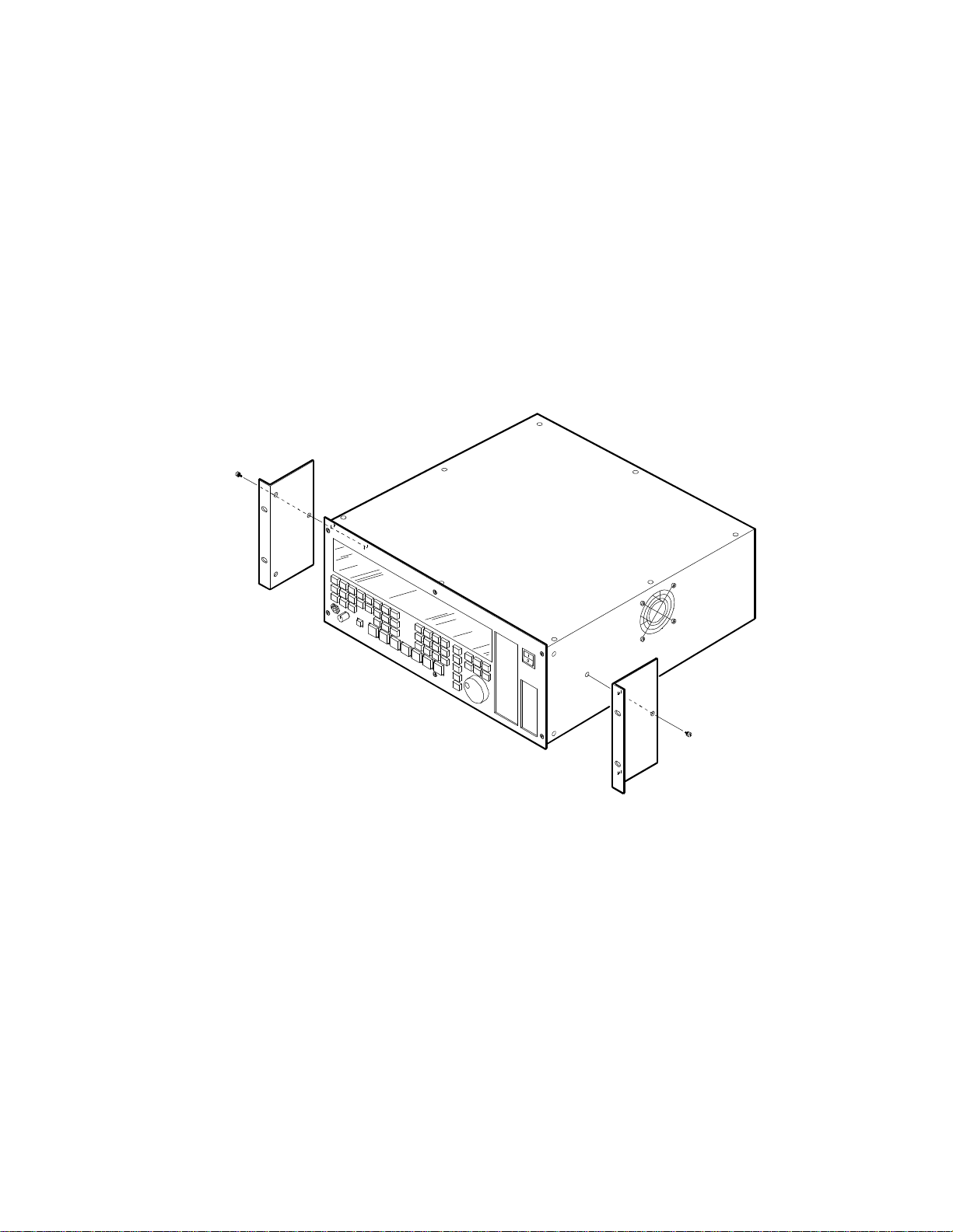
Rack Ears Kit For rack mount installation, the two rack ears may be attached to the front sides of
the MMP-16 chassis using the six 8-32 x 3/8” Phillips head screws included in the
MMP-16 materials kit. The MMP-16 can be used without the rack ears for desktop
applications.
MMR Bus A three-foot sync cable for synchronizing the operation of multiple MMP-
Sync Cable 16’s together via the rear panel MMR bus connectors.
RS422 Cable A 9-pin RS-422 (232) cable for attaching the COM port to a terminal for running
field diagnostics. Also may be used for 9-pin serial connections.
Kingston One Kingston removable drive carrier is included with the system. This
Removable carrier allows drives to be hot-swapped while the system is powered on. It
SCSI Drive is necessary to install a SCSI drive from the list of approved drives into the
Carrier Instructions Kingston carrier before you can playback audio using the carrier with the MMP-16.
The instruction manual for installing drives in the Kingston carrier is in the MMP16 materials kit.
AC Power Cord A six-foot (1.83 Meter) IEC AC Mains cord set is included with the MMR-8. The
mains connector for 115 VAC systems is USA standard. A six-foot (1.83 Meter)
AC Mains cord set for use in Europe, proper for the country of use will be supplied
by your TASCAM dealer. Attach the AC connector in accordance with local
requirements.
Toolkit As a convenience, a small tool kit consisting of a “tweaker” and a small
screwdriver is included in the zip-locked plastic bag in the materials kit. The
“tweaker” may be used for making any necessary adjustments to the analog trim
pots on the analog audio output board.
MMP-16 TASCAM MMP-16 Owner’s Manual • Chapter 2 • Installation
Page 22
General Guidelines
Mounting Rack Ears
The MMP-16 is a self-contained sixteen channel digital playback device designed to be mounted in a
standard 19” (48.26 cm) IEC equipment rack in either the mix studio or a dedicated machine room in a
professional audio recording facility. As such, each MMP-16 is housed in a steel chassis 19-inches (48.26
cm) wide by 17 ¼ inches (43.81 cm) deep by 7-inches (17.78 cm) tall. Each MMR-8 requires 5U (7inches or 17.78 cm) of rack space.
Integral rack ears are provided with the chassis. If the unit is not rack-mounted, the rack ears do not need
to be installed onto the MMP-16 chassis. For rack mounting, install one rack ear to the front of each side
of the MMP-16 (three Phillips screws per side are supplied for fastening the rack ears to the chassis).
Figure 2-1. Rack Ear Installation
24 TASCAM MMP-16 User’s Guide • Chapter 2 • Installation MMP-16
Page 23
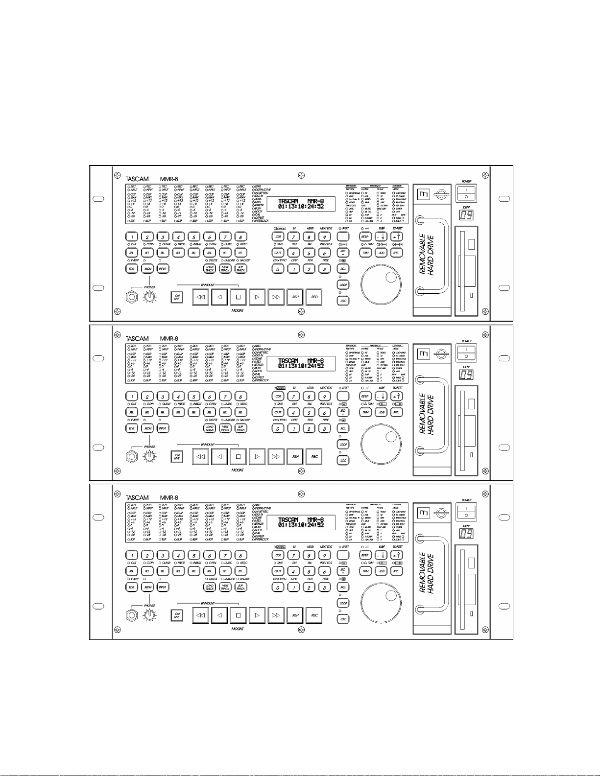
25
Installing Multiple MMP Units
Multiple units can be mounted one on top of the other when forced air rack ventilation is provided. A oneinch clearance is required on both sides of the MMP-16. In facilities with raised computer room-style
flooring, a ventilation opening in the floor is recommended. In no case should the internal rack
temperature ever exceed 110 degrees Fahrenheit (43 degrees Centigrade) during normal operation (as
measured at the rear of any of the MMP-16s in the system).
Multiple MMR-8 Rack Installation
MMP-16 TASCAM MMP-16 Owner’s Manual • Chapter 2 • Installation
Page 24

AC Mains and Grounding (Earthing) Considerations
Each MMP-16 requires one AC mains connection. A standard six-foot (1.83 Meter) power cord set is
included with each MMP-16 wired for the USA standard. A six-foot (1.83 Meter) AC Mains cord set for
use in Europe, proper for the country of use will be supplied by your TASCAM dealer. The AC mains
outlet must be capable of delivering 230 watts (2 amps) for each MMP-16 in the system. The main power
supply has a 115/230 VAC switch on the back of the unit. This switch should be set to match the facility
power level.
An unswitched female IEC convenience outlet is located on the rear panel of each MMP-16. In normal
use there is no connection to this outlet, although other electronics equipment using IEC plugs, and
drawing less than 120 watts total, can be connected to this outlet using the appropriate male-to-female
IEC power cord (like those used with computer monitors).
A facility-wide UPS system is recommended for protecting the MMP-16, and all your audio equipment,
from power line spikes, surges, brownouts, and line failure. If a facility-wide UPS is not available, each
MMP-16 should be connected to a home computer-type surge/spike protection system (of 250 watts
minimum) which is then plugged into an isolated ground AC outlet.
Caution: Grounding (Earthing)
Do not defeat the AC cord U-ground as this will present a potentially dangerous operator
hazard. Using an isolated ground outlet ensures the proper chassis grounding to the
mains “power company” ground. Using only isolated ground outlets throughout a facility
will prevent audio ground loops caused by AC outlets with different ground potentials. A
Ground Stud is provided on the back panel for chassis grounding of the MMP-16.
Audio Cables
Analog Output All analog output on the MMP-16 is done through a pair of 25-pin
D-sub connectors which are pin-compatible with the TASCAM DA-88 connector.
TASCAM DA-88 DB-25 to XLR cables, with either male (output) or female
(input) XLR connectors, are available from your authorized TASCAM dealer.
Digital Output DA-88 analog output cables should be used as digital out cables (NOT TDIF
cables). This arrangement provides four stereo AES/EBU digital outputs on each
DA-88 cable, for a total of 16 channels of digital audio output.
26 TASCAM MMP-16 User’s Guide • Chapter 2 • Installation MMP-16
Page 25
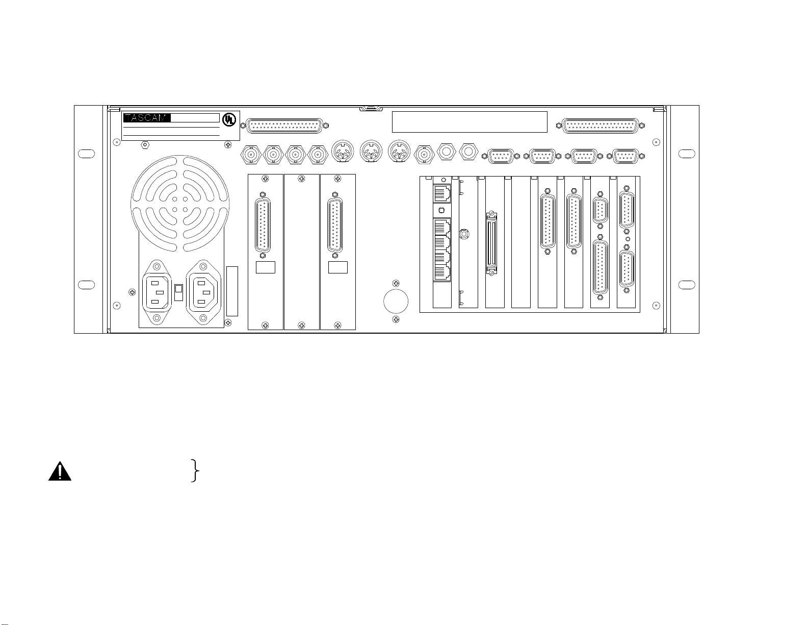
27
MMP-16
Not intended for public
•
•
MMP-16 Back Panel for Serial Numbers up to 01344
MODULAR MULTITRACK PLAYER
TEAC CORPORATION
115 / 230 ~, 2.0 / 1.0 A,
SERIAL NO.
MODEL NO.
MADE IN USA
50 - 60Hz
R
LISTED
XXDK
UL1950
E1XXXX
PARALLEL TRACKS
WORD CLOCK
VIDEO
THIS DEVICE COMPLIES WITH PART 15 OF THE FCC RULES. OPERATION IS SUBJECT TO THE
FOLLOWING RESTRICTIONS: (1) THIS DEVICE MAY NOT CAUSE HARMFUL INTERFERENCE, AND
(2) THIS DEVICE MUST ACCEPT ANY INTERFERENCE RECEIVED, INCLUDING INTERFERENCE THAT
MAY CAUSE UNDESIRED OPERATION.
MIDI
VITC
TIME CODE
LYNX
PARALLEL TRANSPORT
EDITOR TRANSPORT
IN
CHANNEL
115/230 VAC 1/0.5 A
9 - 16
AUXILIARY OUTLET
OUT
ANALOG OUT
IN
OUT
IN
ANALOG OUT
CHANNEL
1 - 8
OUT
THRU
IN IN
OUT
DIGITAL
DIGITAL
OUT
OUT
1 - 8
9 - 16
BOB SCSIPRX SPARE DIO 16AIO 16 UIB SYNC
Figure 2-3. MMP-16 Back Panel
MMP-16 Back Panel Connections
The MMP-16 back panel has connectors for analog and digital audio output, as well as various types of synchronization and control signals. The following
MMP back panel connections are described in this chapter, and the pin outs for many of these connectors are given in Appendix D: Cable Information.
• Analog audio out (x2)
• Digital audio I/O
• Biphase in (BOB)
• Biphase out (BOB)
telecommunication network connection
• Mono mix audio out (PRX)
• SCSI
• Remote control (UI/B)
• MMR bus (Sync)
Word clock in
• Word clock out
• Video in
• Video out
• Midi in
• Midi out
• Midi thru
Time code in
• Time code out
• Lynx (2 connections)
• Editor (Sony 9-pin)
• Transport (Sony 9-pin)
• Parallel Tracks
• Parallel Transport
MMP-16 TASCAM MMP-16 Owner’s Manual • Chapter 2 • Installation
Page 26
MMP-16
Not intended for public
network
•
•
MMP-16 Back Panel for Serial Numbers 01345 and above
2.0 / 1.0 A,
MODEL NO.
230 W
MODULAR MULTITRACK PLAYER
TEAC CORPORATION
115 / 230 ~,
SERIAL NO.
50 - 60Hz
R
LISTED
XXDK
UL1950
E1XXXXMADE IN USA
PARALLEL TRACKS
WORD CLOCK
VIDEO
MIDI
THIS DEVICE COMPLIES WITH PART 15 OF THE FCC RULES. OPERATION IS SUBJECT TO THE
FOLLOWING RESTRICTIONS: (1) THIS DEVICE MAY NOT CAUSE HARMFUL INTERFERENCE, AND
(2) THIS DEVICE MUST ACCEPT ANY INTERFERENCE RECEIVED, INCLUDING INTERFERENCE THAT
MAY CAUSE UNDESIRED OPERATION.
TIME CODE
LYNX
PARALLEL TRANSPORT
EDITOR TRANSPORT
IN
CHANNEL
115/230~VAC 1/0.5 A
9 - 16
AUXILIARY OUTLET
OUT
ANALOG OUT
IN
OUT
IN
ANALOG OUT
CHANNEL
1 - 8
OUT
REMOTE
THRU
IN
OUT
DIAG
BLANK
BOB NETSCSI M 2 BLANK 9-16
ADIF ADIF
1-8
MMP-16 Back Panel Connections for Serial # 01345 and above
MMP units with serial numbers starting at 01345 and higher have a different arrangement for back panel connectors than previous units. The arrangement
of connectors for serial numbers 10345 and above are shown in the drawing above and are listed here.
• Analog audio out 1-8
• Analog audio out 9-16
• AES Digital audio Out (labeled ADIF 1-8 and ADIF 9-16)
• Biphase In (BOB)
• Biphase Thru (BOB)
• Mono mix audio out (M2)
• SCSI
telecommunication
• Remote control
• MMR bus (M2)
Word clock in
• Word clock out
• Video sync in
• Video sync out
• Midi in
• Midi out
• Midi thru
• Time code in
• Time code out
Diagnostic port
• Lynx (2 connections)
• Editor (Sony 9-pin in)
• Transport (Sony 9-pin out)
• Parallel Tracks
• Parallel Transport
• Network (for OPTIONAL 100Mbit
Ethernet card)
28 TASCAM MMP-16 User’s Guide • Chapter 2 • Installation MMP-16
Page 27

29
Audio Connections
All audio outputs (both analog and digital) of the MMP-16 use DB-25 connectors. The pin configuration
used on the DB-25 analog audio connectors is identical to that used for TASCAM DTRS format digital
tape machines such as the DA-88. Two female DB-25 connectors are used for the analog connections, one
for channel 1-8 and the other for channels 9-16, as labeled on the MMP back panel. Each of the digital
outputs uses a female DB-25 connector to carry eight channels of AES/EBU digital output signals (two
sets of four stereo pairs). These are labeled as digital outputs 1-8 and 9-16.
Analog Output Connections
All analog outputs use balanced signals designed to mate with standard 600-ohm devices using +4 dBu
levels. Analog audio processing is done on two separate 20-bit Digital to Analog converter cards mounted
within the MMP-16. These converters are mounted in a special shielded cage within the MMP and are
attached via ribbon cable to a card (labeled AO) plugged into one of the system ISA bus slots on the PC
motherboard. These D/A boards have their own power supply separate from the main PC power supply.
Max load is 12.28 VRMS.
Digital Output Connections
Two female DB-25 connectors are used to provide four stereo digital outputs each, for a total of sixteen
channels of digital audio output. Two TASCAM DA-88 analog I/O cables should be used as digital
output cables. Even though the MMP-16 has no audio inputs, the digital input 1&2 pair on the first digital
input cable is the default reference input for the AES/EBU clock reference. This can be changed to use
digital input 3, 5, or 7 from one of the other three digital input pairs using Setup Menu 600 (Dig In Ref
Track).
NOTE: The digital clock signals coming from any external device connected to the AES/EBU inputs will
force the MMP-16’s internal clock to try to lock to it when digital input is selected (Setup Menu 500).
This can cause playback problems if the clock source is not accurate. If this occurs set that track to use the
sample rate converter in Setup Menu 500 (Input Source).
Monitoring Connections
For monitoring at the MMP-16 there is a mono headphone jack on the front panel (compatible with stereo
headphones of either low or high impedance). For studio Cue or remote monitoring there is a rear panel
line level mono mini phone jack. It is an unbalanced output designed to be connected to external
amplification.
The front panel headphone monitor jack is controlled by the LEVEL control located next to the jack on
the front panel. Press the MON key and select the desired tracks using the Track Select keys to choose
which of the MMP-16 tracks will be summed to appear at the headphone jack output. The rear panel jack
is a pre-LEVEL control, so it is a fixed line level output (-10 dBu), and it always presents a summed
output of the audio channels selected using the MON function on the front panel.
MMP-16 TASCAM MMP-16 Owner’s Manual • Chapter 2 • Installation
Page 28

Timecode and Video Reference Signals
To accurately synchronize the MMP-16 to film or video, or with other audio playback equipment, some
method of providing a stable timing reference must be used. Because the MMP-16 is very flexible, there
are numerous methods one could use to connect film and video equipment. The best method depends
upon the chosen method of sync, the other equipment that is being controlled, and whether the MMP-16
will be the master or a slave to the other equipment. This section covers the various reference signals
available on the MMP-16 system and their applications.
Video In/Out
Most video post houses have a common house sync signal to lock all the audio and video equipment in
the facility to a standard video reference signal. This insures that all devices receiving the house sync
signal will lock together to the edge of the video frame. The house sync signal can be black burst,
composite sync, or color bars in NTSC or PAL format. The house sync video reference signal should be
connected to the VIDEO IN connector on the back of the MMP-16. To loop the connection through the
MMP, connect the MMP VIDEO OUT to the next device that will use the house sync signal. If there is
not a loop through connection then the VIDEO OUT may need to be terminated, depending upon the
facility signal design. To set the MMP frame reference to use this video input, choose setup menu 001,
Frame Reference, and set the value of this parameter to be Video Reference.
SMPTE/EBU Time Code In/Out
The MMP has two stereo phone jack connections using ¼” Tip/Ring/Sleeve connectors (with the tip
being + and the ring being - on a balanced signal) for synchronizing the operation of the MMP to other
devices using SMPTE/EBU Longitudinal Time Code (LTC). To synchronize the MMP to an external
device which outputs SMPTE/EBU LTC, connect the time code audio output of the master device to the
MMP TIME CODE IN jack. The MMP-16 can also generate a stable SMPTE/EBU time code output
(equivalent to a time code track signal) that can be used to synchronize external equipment or to stripe
time code onto tape. The TIME CODE OUT jack will always output SMPTE/EBU LTC when the MMP
is playing.
30 TASCAM MMP-16 User’s Guide • Chapter 2 • Installation MMP-16
Page 29

31
Biphase Connections
Biphase is a control signal typically generated by a film projector and is traditionally used to interlock the
operation of the film with sprocketed magnetic tape machines. The Biphase Operations Board (BOB) on
the back panel of the MMP has four biphase input connections and one biphase throughput connection for
synchronizing the operation of the MMP-16 to film transports. Use Setup Menu 100, Sync Group, to
select which of the four Biphase inputs (Sync Groups) will control the system. The biphase connections
use 6-pin modular RJ-12 connectors (like those used on commercial phone systems) and twisted multipair cabling (Category 5 Ethernet). Up to 100 feet of cable can be typically run from a biphase device to
the MMP-16 or vice versa. The pinout diagram for these connectors is given in Appendix D: Cable
Information.
Unlike time code, Biphase gives only speed and direction and does not contain an absolute
address. To set the MMP to lock to biphase, use Setup Menu 000, Control Mode. The various
biphase parameters such as frame rate, pulse rate, acceleration, etc. are set in the 300 series Setup Menus.
Not intended for public telecommunications network connection.
Digital Audio Sample Reference Connections
In combination with a frame reference for video and film, there may also be a sample reference for the
audio. The sample reference can be taken from the digital input 1&2 on the Digital output cable, the
frame reference, the Word Clock input (if there is an active signal on that input), or the system’s internal
clock source. These connections are described here in more detail.
Word Clock
Word Clock is a digital reference signal used by many digital editors and digital tape machines. This
permits two digital audio devices to synchronize their sample clocks to facilitate digital audio transfers
between machines, and to insure that they are running at precisely the same sample frequency. The signal
is transmitted on an unbalanced coaxial cable that terminates into a BNC connector at the MMP-16 end.
The MMP-16 has both a digital WORD CLOCK IN and a digital WORD CLOCK OUT connection using
BNC connectors.
When an external tape machine is to control the sample rate of the MMP-16, connect the Word Clock
output from that machine to the WORD CLOCK IN on the MMP-16. When the MMP-16 is to control the
sample rate of an external machine connect the WORD CLOCK OUT from the MMP-16 to the Word
Clock In on the controlled machine. The maximum practical cable distance is up to 100 feet. Use setup
menu 002 to select the sample reference for the MMP-16 system. Normally this is a 48 kHz TTLcompatible (5 volt) signal.
AES/EBU Sample Rate
To lock the digital sample clock to an AES digital audio source, the audio sample reference for the MMP16 can be taken from the digital audio input 1&2 pair on the connector used for the AES digital output.
Use setup menu 002 to select the sample reference for the MMP-16 system.
MMP-16 TASCAM MMP-16 Owner’s Manual • Chapter 2 • Installation
Page 30

MIDI Connections
The MMP-16 has MIDI (Music Instrument Digital Interface) In, Out, and Thru connectors. These are
used for sending MIDI Time Code and for controlling the transport via MIDI Machine Control.
The MMP MIDI OUT connector carries a MTC signal generated by the MMP-16 whenever the unit is in
Play. To slave MIDI devices that can follow MTC (MIDI Time Code) to the MMP-16, connect the MMP
MIDI OUT connector to MIDI In port of the external device. The MIDI out signal (and the MIDI
Through signal, if it is set as a second MIDI output) will contain any MMP-16 responses to the MMC
input commands in addition to MTC generated by the MMP-16 from the time code reference source.
The MIDI IN port on the MMP can receive MIDI Machine Control messages for operating the MMP’s
basic transport control functions. The MIDI THRU jack on the MMP will pass through any MIDI signals
appearing at the MMP MIDI IN port.
External Controllers & Bus Connections
In most installations the MMP-16 will be rack mounted in a machine room and thus will either be remote
controlled through slaving to another time code-based machine (typically a VTR) or to a biphase machine
(typically a film transport). Any controller that has a Lynx port can also directly control, or be controlled
by, the MMP-16 (the TimeLine Lynx Keyboard Control Unit and the TimeLine Lynx-2 module are two
examples). There is also a fully featured remote, the TASCAM MM-RC, which is specifically designed to
control multiple MMR and MMP units.
Lynx Bus / KCU Connection
The TimeLine Lynx Keyboard Control Unit (KCU) can be used with the MMP-16. Multiple units may be
daisy-chained using either of the two LYNX connectors as input. The other LYNX connector could be
tied to another MMP-16, or to a Lynx module for controlling other tape machine transports. The Lynx
KCU can control a total of up to six machines.
MMR Sync Bus Connections
The real power of the MMR-8/MMP-16 system comes into play when multiple MMP-16s are tied
together using the MMR Bus to create larger “virtual” audio playback machines. The MMR bus supports
up to 100 MMP-16s, all tied together to create up to an 800-track playback system that could be
controlled by a single MMP-16, MM-RC Remote, Lynx KCU, or other machine remote controller.
The MMR Bus connects each MMP-16 using a 15-pin connector located on the SYNC card connector on
the MMP back panel. Two DB-15 connectors are provided on the back of each MMP-16 so that multiple
machines can be daisy-chained together. The system is auto terminating. To add MMP-16 units to the
system, connect a cable from the last unit in the chain to the new unit.
The MMP Bus is made active on each machine by choosing the MMP Master or Slave setting in Setup
Menu 110, MMP Bus Request. All of the MMP-16s that are tied together can then be software divided
(Setup Menu 100) into four Sync Groups, each featuring fully independent control within their group. All
of the MMR/MMP machines that are connected, Online, and set to the same sync group can then be
controlled together. The MMR Bus thus turns three MMP-16s into a single 48-track playback machine,
six MMP-16s into a 96-track machine, and so on up to 100 MMP-16s functioning as a single 1600-track
playback machine. Any MMP-16 tied onto the MMR bus can also be individually taken off-line and
controlled locally at any time. MMR and MMP Units can be added or dropped from Sync Groups using
the Online key on the front panel.
32 TASCAM MMP-16 User’s Guide • Chapter 2 • Installation MMP-16
Page 31

33
Serial Transport Connection
The TRANSPORT connection uses the industry-standard RS-422 Sony 9-pin P2 protocol (Ampex VPR-3
is also supported) for controlling external serial transports such as audio or videotape machines. It is
intended for transport control of a single external device. This port will send out the appropriate transport
commands when the transport functions of the MMP are engaged through the front panel or via the MMRC Remote controller. Use Setup Menu 000 (Control Mode) to set the MMP to control external devices
via the Serial Transport connection. A video reference source is recommended for this type of operation.
Serial Editor Connection
The EDITOR connection uses the industry-standard RS-422 Sony 9-pin P2 protocol. The Editor
connection allows for controlling the MMP-16’s transport functions from a standard Video editor
controller or other external device. Use Setup Menu 000 (Control Mode) to set the MMP for control via
the Editor connection. A video reference source is required for this type of operation.
Parallel Transport
The PARALLEL TRANSPORT connector allows use of remote control devices that operate by sending
messages via parallel signals for the motion control keys. There are +12 volts available to drive switch
lamps in conjunction with the tally outputs that are available for each key. The pinout diagram for the
Parallel transport connector is given in Appendix D: Cable Information.
Parallel Tracks
Since there are no audio inputs on the MMP-16, the PARALLEL TRACKS connector has no function in
the current software release. The Parallel tracks connector may be used in future releases of the MMP-16.
MMP-16 TASCAM MMP-16 Owner’s Manual • Chapter 2 • Installation
Page 32

Connecting External SCSI Media
Black Box Corporation -
Paralan Corporation -
The MMP-16 SCSI interface card is pre-set to SCSI ID 7. The internal Kingston drive receiver in the
MMP-16 is set to SCSI ID 0. Each device added in the SCSI chain must have a unique SCSI ID number
or else the MMP-16 will not boot properly.
External SCSI connections should be made using the shortest possible length of double-shielded SCSI-2
cables with 110 ohms impedance. Only the last drive in the chain is terminated. All other drives must
have their terminating resistors removed or have termination jumpers set to off (including those drives
placed in the MMP-16 internal drive slot). SCSI cables are readily available from most computer stores.
For the most reliable operation, the total length of all SCSI cabling must not exceed 15 to 20 feet.
All drives must be pre-formatted using a single partition. Drives with capacities of up to 9 GB have been
tested and found suitable for use with the MMP-16. The MMP-16 system plays all audio from separate
uncompressed 16-bit or 24-bit linear files. Approximately 5 MB (Megabytes) of disk space is required for
each minute of audio recorded per track. Thus a 4 GB drive can hold about 12 track hours of 16-bit audio,
while a 2 GB drive will hold about 6 track hours.
SCSI Cables
There is a considerable difference in quality and performance of cables used to connect SCSI devices. It is
imperative that users pay close attention to this issue.
Cable Quality
High quality SCSI cables are essential for proper MMR/MMP system performance. Low quality cables,
which are often thin, may cause data transmission errors, file corruption, and system malfunctions. This is
often due to improper and insufficient grounding, incorrect pin wiring, and unwired pins. The following
SCSI cable manufacturers are highly recommended as a source for MMR/MMP SCSI cables:
www.paralan.com
4655 Ruffner St., San Diego, CA 92111
Tel. (619) 560-7266 || Fax 619-560-8929
email: scsi@paralan.com
www.blackbox.com
1000 Park Drive Lawrence, PA 15055-1018
Tel: 724-746-5500 || Fax: 724-746-0746
email info@blackbox.com
Cable Length and Device Support
The MMR/MMP SCSI host card supports from one to eight SCSI devices. However when one to four
SCSI devices are connected, total cable length should not exceed three meters. When five to eight SCSI
devices are connected, total cable length should not exceed 1.5 meters. Note that total cable length
includes the internal cabling in carriers or drive bays. Thus if a 4-bay drive enclosure contains ribbon
cable internally that measures one meter in length, the external cable must not exceed 2 meters. Improper
cable length often causes an MMR system to freeze while mounting volumes. (Note: Paralan can provide
custom-length SCSI cables).
34 TASCAM MMP-16 User’s Guide • Chapter 2 • Installation MMP-16
Page 33

35
Cabling Wide and Narrow Devices in a System
NARROW SCSI uses 8-bit data transfers. It generally uses a 50-pin connector.
WIDE SCSI uses 16-bit data transfers. It generally uses a 68-pin connector. Wide SCSI may also refer to
32-bit SCSI data transfers but 32-bit wide SCSI is not as common.
Narrow drives should always be placed at the end of a SCSI chain. This is due to the fact that when a
Wide to Narrow connection is made, 8 bits are not passed through, so the Wide drive (and all subsequent
SCSI devices in the chain) receives only 8 bits of data instead of 16. If a Narrow drive is connected after a
Wide drive, the Wide drive still receives all 16 bits of data.
SCSI Termination
A terminator provides electrical circuitry at the end of a SCSI chain to prevent the reflection of electrical
signals when they reach the end of the chain. The SCSI bus requires termination only at the ends of the
SCSI chain, not in the middle. There are several types of SCSI Termination: Passive, Active, Active
Negation, Force Perfect Termination, and Low Voltage Differential.
The MMR/MMP should only use Active terminators. This is because active terminators involve a
voltage regulator to reduce fluctuation effects in termination power to insignificance. This results in more
stable SCSI signals, less signal reflection and fewer data errors. Active negation terminators are most
optimized for Fast- and Ultra-SCSI speeds. Active negation termination is currently not under testing and
thus is not supported by TASCAM.
Kingston Frame Configuration
When configuring a Kingston receiving frame the settings in Figure 1 must be used.
Note: All but one setting are factory defaults. Jumpers should be installed on W3, W1 and pins 1&2 of J6
(Figure 1). Jumper W2 determines termination. In the “A” position (default) termination resistors are
disabled (This is the recommended configuration for most external applications). In certain conditions it
may be desirable to terminate at the frame, for example, if an internal bay is being installed in the
MMR/MMP. If this is the case jumper W2 should be set in the “B” position
MMP-16 TASCAM MMP-16 Owner’s Manual • Chapter 2 • Installation
Page 34

Figure 1
Wide SCSI Cards and Kingston Frames
The MMR/MMP are normally shipped with a narrow Symbios SCSI card. The MMR/MMP units
also support the Symbios SYM8751SP Wide SCSI card. To install a wide SCSI card, use a
grounding strap and follow the installation instructions below:
Removing the Narrow Host Adapter (Symbios SYM 8600SP)
1) Disconnect the 26-pin ribbon cable from J2 on the MMR Biphase Operations Board, and fold out
of the way.
2) Disconnect the 50-pin ribbon cable from J2 on the Symbios SYM8600SP SCSI host adapter.
3) Remove the Phillips head screw that secures the host adapter to the chassis.
4) Carefully remove the host adapter.
Installing the Wide Host Adapter (Symbios SYM8751SP)
1) Prior to inserting the wide host adapter into the PCI slot, connect the 50-pin ribbon cable to J4 on
the SYM8751SP. This connector is located on the side of the card, which makes it very difficult
to install if the card is already in the PCI slot.
2) Insert the wide host adapter into the same PCI slot that previously contained the narrow adapter.
3) Secure the wide host adapter to the chassis with the Phillips head screw.
4) Reconnect the 26-pin ribbon cable to J2 on the MMR Biphase Operations Board.
36 TASCAM MMP-16 User’s Guide • Chapter 2 • Installation MMP-16
Page 35

37
Wide Kingston Drive Frames
The Kingston SCSI drive frame in the MMR is normally configured for narrow SCSI. TASCAM can also
provide MMR/MMP units configured with wide Kingston frames and carriers, and can perform a service
upgrade to remove the existing narrow Kinston frame and carrier and replace it with a wide Kingston
frame and carrier. Contact your TASCAM representative for pricing and availability on these wide units.
Note that a narrow drive carrier will not fit into a wide frame, and vice versa.
It is possible to mount a narrow SCSI drive in a wide Kingston carrier (or vice versa) by means of an
adapter inside the carrier. One source for these adapters and other SCSI cable peripherals can be found at:
CS Electronics
17500 Gillette Ave.
Irvine, California 92614
Tel (949) 475-9100 Fax (949) 475-9119
http://www.scsi-cables.com/Index.htm
CS Model # ADP-9051 is for HD68-pin male to 50-pin male (mounts a wide drive in a narrow carrier)
CS Model # ADP-9056 is for HD68-pin female to 50-pin female (mounts a narrow drive in a wide
carrier).
Approved SCSI Drives
The following disk drives have been approved for use with the MMR-8 as of July 19, 1999:
Drive
Manufacturer
Seagate ST118273LW 6246
Seagate ST19101W 0014
Seagate ST318203LW 0001
Seagate ST318275LW 0001
Seagate ST32272N 0876
Seagate ST34371N 0484
Seagate ST34573N 5958
Seagate ST34573W 5764
Seagate ST39102LW 0005
Seagate ST39173N 5764
Seagate ST39173W 5764
Seagate ST39173LW 6264
Drive
Model
Firmware
Version
Nikon* DD53-SIP Beluga AV Unknown
IBM DCHS09F 2222
Manufacturers frequently release new drive models and obsolete other drive models. The most current list
of approved drives can be found on the TASCAM web site at http://www.tascam.com .
* Users should be aware these drives do not perform as well as hard drives. Test results with the NIKON
Beluga drive with 1K/sector media show 8 tracks of record and playback in 16- or 24-bit TapeMode is
generally reliable. Non-destructive mode performance is less reliable, especially with heavy edit density.
MMP-16 TASCAM MMP-16 Owner’s Manual • Chapter 2 • Installation
Page 36

DVD RAM Support
The MMR/MMP will support SCSI backup and export to DVD RAM disks as of software version 3.1.
Testing so far indicates that these drives are several times slower than Magneto-Optical disks for
recording and transfers. Playback of a limited number of tracks is possible from a DVD RAM disk, but
maximum performance seen to date is 6 channels of 16-bit material in TapeMode.
LIMDOW Optical Drives
For backing up files, and for ease of moving smaller projects around, we recommend using a
“LIM/DOW” (Light Intensity Modulation / Direct Over Write) type optical disk. The LIM/DOW
technology achieves better performance than is available on older types of Magneto-Optical media, which
must execute an erase pass before they can write new data to the disk. The Nikon Beluga AV MO
(Magneto-Optical) disk drive has been tested and rated to perform well when used with the MMP-16. A
chart of currently tested and certified disk drive media is given in Appendix B, MMR Approved Drives
List. The results from performance tests of the NIKON Beluga AV MO drive with 1K per sector media
are also given there. It is possible to use other removable media such as the IOMEGA Jaz drive and the
SyQuest Syjet, but these do not provide the same level of performance for recording as a hard drive and
they are more fragile than optical drive media. Use these devices at your own risk, as they are not
supported as primary record or playback devices DAT, Exabyte and other streaming tape device cannot
currently be used with the MMP-16 system.
38 TASCAM MMP-16 User’s Guide • Chapter 2 • Installation MMP-16
Page 37

39
Remote Controllers for the TASCAM MMP-16
TASCAM MM-RC The TASCAM MM-RC is a dedicated remote control unit designed specially for
use with the MMP-16 and the MMP-16 sixteen channel player unit. It connects to a
special remote connector on the UI/B card on the back of the MMR and MMP
units. This remote allows complete control of all attached functions of the MMR
and MMP units, including all setup menus. It also allows for machine grouping as
well as system wide control of all attached units. A total of up to 100 units (any
combination of MMR and MMP) can be controlled from the MM-RC.
Lynx KCU The TimeLine Lynx Keyboard Control Unit (KCU) is a tabletop controller which is
typically used in conjunction with Lynx 2 synchronizer modules. It provides a time
code display, motion control functions (including a jog/shuttle Wheel), track
selections, and audio editing functions for most professional video and audio
transports. The KCU can remotely control the operation of a total of up to six
transports including MMP-16s. When used with the KCU 900 software, the Lynx
KCU unit allows control of the following MMP-16/MMR-8 functions:
• Transport Control
• Track Record Arm/Select (Record arm only for MMR-8)
• Slip Track/Region
• Undo/Redo
• Goto Prev/Next Edit
• Goto Head/Tail
• Clear/Paste
The Lynx KCU may be directly connected to either of the two integrated Lynx
ports on the MMP back panel. The second Lynx connector provides a loop thru
connection to an external Lynx module for control of other devices from the KCU.
The TimeLine Lynx KCU is available from:
TimeLine Vista, Inc.
1755 La Costa Meadows Drive, Suite B
San Marcos, CA 92069
Tel: (760) 761-4440 Fax: (760) 761-4449
Keyboard Operation (with MM-RC option)
The optional MM-RC (Remote Control unit) has a keyboard connector located on the rear panel which
accepts a standard PC-AT style keyboard. The purpose of the keyboard is to facilitate selecting menu
items while in the Setup Mode and to make it easier to name Projects and Tracks. There is no way to
connect a keyboard directly to the MMR or MMP – this must be done using the MM-RC.
Note: The internal software of the MM-RC will be automatically updated when an MMR-8 or MMP-16 is
booted while attached to the MM-RC. Be sure the power switch of the MM-RC is on while the
MMR/MMP unit is started so the unit can sense the presence of the MM-RC remote.
MMP-16 TASCAM MMP-16 Owner’s Manual • Chapter 2 • Installation
Page 38

Using the PC Keyboard
Use the keyboard to perform the following data entry tasks on the MMR or MMP:
• Enter Project and Track names directly by using the standard alphanumeric keys.
• Enter Tape Mode Start time, Pre-Roll and Post-Roll directly using the number keys.
• Access Menu Banks directly by using the Number keys.
• Use the Up and Down arrow keys on the keyboard to scroll through the Setup Menus.
• Use the Up and Down arrow keys to scroll through menu parameters. Once the desired menu is
reached, press F1 to toggle the Trim key function.
• Pressing Enter on the keyboard has the same effect as pressing STO on the MMR or MMP front panel
and will store the parameter selection displayed in the LCD.
Not all keys on the PC keyboard are active. Use the following keys:
F1 – Press F1 to enter Setup. Once Setup Mode has been entered, F1 will toggle the TRIM key on the
MMP front panel.
Escape (Cancel) key – This key is equivalent to the Cancel (CLR) key on the MMP front panel. Press
Esc to leave the Setup Mode and return to the Normal Display State.
Arrow keys - These serve the same function as the Arrow keys on the MMP front panel.
Enter key - Equivalent to STO on the MMP front panel. When a menu or parameter setting has been
changed pressing Enter stores the new parameter.
Shift key - Acts like a standard keyboard Shift key, but will only work in conjunction with Letter keys
and the Minus key.
Letter keys – May be used shifted or unshifted. Note that most punctuation keys are not supported.
Minus key - Shifted for Underscore, or unshifted for Minus/Hyphen.
Caps Lock - Works like a standard keyboard Caps Lock key.
Num Lock - When Num Lock is active (Num Lock is lit on the keyboard) use of the numeric Keypad is
enabled. The Number keys and the Enter key are active in this mode, and they function exactly like they
do on the keyboard. When Num Lock is not active (the Num Lock light is not lit), the numeric keypad
serves only as up (8), down (2), left (4), and right (6) arrows.
40 TASCAM MMP-16 User’s Guide • Chapter 2 • Installation MMP-16
Page 39

41
Powering Up the System
TASCAM MMP-16
The MMP-16 comes from the factory with the operating system and MMP-16 software pre-loaded onto
the internal hard drive. At POWER ON, the front panel LCD should display the following message:
© TimeLine 1996 - 99
If this message is not seen, the front panel is not operating correctly, and you should contact TASCAM
technical support for assistance. As the system software is loaded, the LCD will go blank, then after a few
seconds will display the message “Mounting Volumes”. Any SCSI drive that will be used by the system
must be attached to the SCSI bus and powered on at startup in order to be available for mounting. After
all volumes have been mounted, the display will be initialized with a fill character (all character positions
will be filled), and will pause as the power-up settings are restored. Various LEDs may turn on and off
during this process. The entire sequence of events may take up to 30 seconds. When it is complete, the
front panel display should show something like:
01:00:00,00.00
01:00:00,00.00
This indicates the system is now ready to go to work. Any other indication is an error condition. Should
an error occur, note the message, if any (if it is a long message, scroll using the left/right arrow keys), and
contact TASCAM technical support.
Verifying MMP-16 Installation
Once the MMP-16 is properly mounted in a rack or has been positioned on or in the studio furniture,
follow these steps to complete, or to verify, the proper installation of your MMP-16 system:
1. Connect the MMP-16’s 25-pin female D-sub analog output connector to the mixing console’s
tape returns or to those line-level inputs normally used for tape playback. Refer to Appendix D:
Cable Information for the connection pin outs for the analog output connectors.
2. Install the removable drive into the front panel of the MMP-16 (if it is not already installed).
Slide the drive into the front panel opening and press on the drive to fully seat it in the holder.
Turn the key to lock the unit into place and to connect the drive power. The LED indicating the
drive SCSI address will flash until the drive has finished spinning up and is ready for operation.
3. If external SCSI hard drives will be incorporated into the system, connect a SCSI-2 cable from
the MMP-16 rear panel SCSI-2 port to one of the SCSI ports on an external SCSI drive housing.
SCSI NOTES: Each device connected to the SCSI bus must have a unique SCSI ID number.
Configure the MMP-16’s removable hard drive (installed in the Kingston carrier) to use SCSI ID
0. The internal SCSI interface board uses SCSI ID 7. Thus, no other drive in the system can use
these SCSI ID numbers. Also, only the last drive in the SCSI chain can be terminated. All other
drives must NOT be terminated. If two drives are set for the same SCSI ID number, or if any
drive other than the last one in the chain is terminated, it will prevent the MMP-16 from properly
functioning. See Connecting External SCSI Media (in this chapter) for additional information.
MMP-16 TASCAM MMP-16 Owner’s Manual • Chapter 2 • Installation
Page 40

4. Connect the MMP-16 to the applicable timing reference source and to the appropriate remote
control interface
a. To connect the MMP-16 to a film transport, connect the biphase sync output from the
projector to one of the four biphase inputs. The four biphase inputs are numbered 1 - 4 from top
to bottom. Any, or all, of the inputs can be connected. Use Setup Menu 100, Sync Group, to
select which of the four Biphase inputs (Sync Groups) will control the system.
b. To connect the MMP-16 as a slave to a video machine, first connect a source of Video Frame
synchronization to the MMP-16’s VIDEO IN (either the Video Reference out from a video deck,
or a Video black burst signal). This is normally a loop-through connection so the MMP16’sVIDEO OUT jack should be terminated if it is not connected to another machine. Next
connect the Time Code signal from the video to the MMP-16, using the SMPTE/EBU TIME
CODE IN (LTC) connector. Use the RS422 Sony 9-Pin Editor port to control the MMP-16 via
Sony protocol. To connect the MMP-16 as a master for a video deck, connect the TRANSPORT
connector to the video deck’s Sony P2 protocol-compatible remote control connector.
c. To connect the MMP-16 to other audio devices, connect the TIME CODE IN/OUT
connectors. If the other devices do not read or transmit SMPTE/EBU time code, but they do read
MTC (MIDI time code), then connect the MIDI IN/OUT/THRU as required.
To connect multiple MMP-16 Players together, daisy chain them using the MMR Bus (the
15-pin SYNC connectors). A 3-foot MMR bus cable is provided with each MMP-16 for this
application. Since each connector parallels the other, connection order is not critical. The MMR
Bus is self-terminating.
e. If remote control capabilities are desired, then connect a TASCAM MM-RC remote control
unit to the 25 pin D-sub connector on the UI/B board on the back panel of the MMP-16. Some
functions of the MMP-16 can also be controlled via the TimeLine Lynx Keyboard Control Unit
(KCU) by connecting the KCU to either LYNX connection (they operate in parallel, so either
one may be used) on the MMP-16 back panel. If necessary the other LYNX connection can be
daisy-chained to other equipment (MMP-16, a Lynx-2 controller, etc.).
Software Updates
Software updates are available on the TASCAM Web site at http://www.tascam.com, and may be
downloaded onto one or more floppy disks. To install the software update, insert the floppy disk (or Disk
1, if multiple disks are received) into the front panel floppy drive while the unit is operating normally.
Access Menu 995 (Load Software) and press STO. The system will ask “Are you sure?” Confirm the
floppy is properly inserted and press STO again to confirm. If multiple disks are supplied, the operator
will be prompted via the display to remove Disk 1 and place Disk 2 into the drive. After the software
update is installed, the system will display a message that the update is complete, and will display a
checksum number (written on the floppy update disk for reference) to verify that the installation has been
successful. Remove the floppy disk and recycle the power to operate the unit with the new software
installed. All system floppy disks should be kept in a secure location in case they are needed in the future.
42 TASCAM MMP-16 User’s Guide • Chapter 2 • Installation MMP-16
Page 41

43
Factory Default Settings
The MMP-16 is shipped from the factory using a pre-defined set of operating parameters. The factory
default settings can be changed in the field at any time through a system of Setup menus that control the
MMP-16 operating parameters. The new value settings will be automatically saved and used at system
start-up as the normal operating parameters of the MMP-16. The system can be reset to use the factory
defaults at any time by accessing menu 901 (“Recall Settings”), and selecting the “Default” value. The
system will then be returned to the factory default settings and is ready to use.
MMP-16 TASCAM MMP-16 Owner’s Manual • Chapter 2 • Installation
Page 42

Chapter 3 MMP-16 Keys and Status Displays
MMP-16 Keys & Definitions
Throughout this manual several abbreviations and written shortcuts are used to define user operations and
machine functions. The following summarizes how these abbreviations and text shortcuts relate to the
operational description:
Keys Refers to the colored front panel keys on the MMP-16. The gray keys are used to
enter time code numbers (on the numeric keys) and to perform various other
common functions. The shift key is the only yellow key. Key use in the text is
indicated through capitalizing the key legends (e.g., LOAD TRACK indicates the
Load Track key is to be pressed).
Shift Key This key, the only yellow key on the front panel, functions like the shift key on a
computer keyboard. Located at the top-right corner of the numeric keypad area,
shift works in combination with selected gray keys, enabling their shifted
functions. The shifted function for each applicable gray key is written above the
key on the front panel metal. Press and release the shift key before pressing any
other key, to “latch” the shift key until the desired key is pressed. This will light the
shift LED above the SHIFT key. Pressing another key while the shift LED is on
will cause that key to execute its shifted function. Once the shifted function has
been activated, the shift LED will go off and the system will return to the normal
non-shifted state. If multiple shifted keystrokes are required, you may also press
and hold SHIFT (the shift LED above the key will stay on) while pressing one or
more gray keys in succession.
In the text “SHIFT+X” indicates the Shift key is used in combination with one of
the gray keys (X) that has a shifted function. Thus, SHIFT+TRIM means “press
and release (or press and hold) the SHIFT key and then press the TRIM key.” In
this case, the MMP-16 will enter Dynamic Trim mode since the shifted function for
the TRIM key is “Dynamic Trim” (which is indicated above the key). To cancel
shift, when the shift LED indicator is on, press SHIFT again, or press CLR.
Text Above Keys Indicates the “shifted function” for that key. Pressing SHIFT+ key, as detailed
above, accesses the shifted function.
Reversed Text
Above Keys Indicates the “alternate” function for the JOG and SHTL keys, and for the STO,
RCL and CLR keys. The alternate functions are used in Setup, Track, Verify, and
Error modes, and while trimming values. In Normal mode, the key functions are
normal (i.e., pressing JOG turns the Wheel into a Jog Wheel). In Setup or Track
modes, pressing JOG indicates a left-arrow function as a cursor or window
movement tool.
44 TASCAM MMP-16 User’s Guide • Chapter 3 • Keys and Status Displays MMP-16
Page 43

45
Mode This term is used to refer to the active Control mode selected by Setup menu 000
and to refer to the Track Select Mode which governs the behavior of the SEL keys.
It may also be used to refer to various operational modes such as Loop, Trim, or
Shift which change the meaning of other keys or controls as long as the mode is
active.
LCD Text To indicate the front panel LCD text, curly brackets are used to enclose the text.
(e.g., {X. 01:00:00,00}) A mono-spaced Courier font duplicates the
spacing and alphanumeric characters shown in the LCD. In the Normal state, the
top line of the LCD typically shows the current “play head” time code, while the
bottom line shows the entry (or other active) register time code. In Setup, Track,
Verify, or Error states, the two LCD lines will change to show various text
messages as indicated in the Functional Overview section of Chapter 2.
MMP-16 TASCAM MMP-16 Owner’s Manual • Chapter 3 • Keys and Status Displays
Page 44

MMP-16 Front Panel
Track Status and
Keypad
Setup and
Removable
Assigned
Identification
Floppy
Drive
Headphone
Transport
Liquid Crystal
Configuration
Key Groups and Displays
Status LEDs
Machine
Metering LEDs
Track Group
Output & Gain
TASCAM
2
1
3
CLIP
MAX
+12
+6
0 0
-6
-12
-25
SLIP
9
CUT
1
EVENT
EDIT MON
MMP-16
54 6 7 11
CLIP
CLIP
MAX
MAX
+12
+12
+6
+6
0
-6
-6
-12
-12
-25
-25
SLIP
SLIP
10
11
COPY
CLEAR
2 3
PHONES
LINE
Group
CLIP
MAX
+12
+6
0-60
-12
-25
SLIP
12
PASTE
4
ON
8 9
Display (LCD)
10
12
CLIP
MAX
+12
+6
0
-6
-12
-25
SLIP
14
OPEN15UNDO
6
DELETE7UNLOAD
TRACK
UNMOUNT
13 14 16
CLIP
MAX
+12
+6
0
-6
-12
-25
SLIP
VIEWLOAD
TRACK
MAX
13
INSERT
5
CLIP
+12
+6
-6
-12
-25
SLIP
15
MOUNT
CLIP
MAX
+12
+6
0
-6
-12
-25
SLIP
16
REDO
8
BACKUP
SLIP
TRACK
TONE
MIDI
ERROR
BUSY
LOCK
OFFSET
INTERLOCK
CANCEL
CLR
TIME
CAPT
LYNX SYNC
0
Group
IN
7
OUT
OFST4RDR
1 2
HEAD
NEXT EDIT
8 9
TAIL
PREV EDIT
5
TIME CODE
SHIFT
YES
STO
6
=
NO
FREE
RCL
3
LOOP
LOC
Wheel Group
29.97
NDF
DF
25
24
Wheel
SAMPLE
INT
AES
WORD
MMR
RATE
48.000
44.100
P. UP
P. DOWN
NON STD.
+/-
SETUP
TRIM
TRIM JOG
FRAME
VIDEO
TC
BIPH
LYNX
EXT RSLV
SYNC GRP
1
2 MMR
3
4
SUBF
-
CONTROLREFERENCE
MODE
LOCAL/BUS
TC CHASE
BIPH CHASE
BIPH TRAN
SER TRAN
EDITOR
VARI
MAST
SLAVE
TC/FEET
+
SHTL
POWER
LYNX
REMOVABLE
HARD DRIVE
IDENT
Drive Bay
Page 45

47
Page 46

48
Front Panel Indicators, Switches, and Displays
Collectively, all the front panel keys and the Wheel are called switches and the LEDs, six motion control
lamps, and the Liquid Crystal Display (LCD) are called indicators. The MMP-16 is manually controlled
through front-panel switches, while system status is shown via the indicators. The front panel switches are
divided into five groups: the track group, the keypad group, the setup & wheel group, the wheel itself, and
the transport (or motion control) group. The functions for each switch in each group and how their
selection affects the indicators are discussed in this section. The MM-RC remote control unit provides
most of the same functions as the MMP front panel. Note that the CLR (clear or cancel) key will almost
always terminate an operation, and is a good first key to try to cancel an operation.
LED Indicators
Most operating parameters and key functions are indicated through LEDs, as are the output signal levels.
Configuration Settings
To the right of the LCD are 34 LEDs used to indicate the Control mode, the frame and sample reference
sources, the time code format, the sample rate being used, the active sync group, and the state of the
MMP-16 buses (master or slave on the MMR or Lynx buses).
Active Mode/Key Indicators
Above most soft-touch keys there are LEDs to indicate the key status. In some cases they indicate that the
shifted function is active. In other cases they indicate a key status. For example, the LOC (locate) key’s
LED will be on while the MMP-16 is locating, turning off to indicate the transport has completed locating
(the time code in the top and bottom lines of the display should then be equal).
The LEDs above the SEL keys indicate which tracks are selected according to which track function key is
also active. The track function key (EDIT, MON, LOAD TRACK, TRACK or SLIP) that is active will
also have its LED turned on. For example, pressing MON will turn on the MON LED, as well as the SEL
LEDs for all the tracks that are currently being monitored in the headphones. Pressing any SEL key will
then toggle the track between monitor on (when the LED is lit) and monitor off (no SEL LED for that
track). If another track mode key is pressed the SEL LEDs will now indicate that mode’s selected tracks.
Track Status and Metering
Immediately above the track select buttons associated with tracks 9-16 in the MMP-16 are 9 LEDs per
track (for a total of 144 LEDs). These indicate audio signal levels (meter LEDs) & track slip status for
each track.
TASCAM MMP-16 Owner’s Manual • Chapter 3 • Keys and Status Displays MMP-16
Page 47

49
Meter LEDs
Each track has its own column of signal level LEDs that read the MMP-16 analog output signal off disk.
Each meter column contains eight LEDs. Functioning much like a tape machine’s peak meters, their
meters have a fixed rise time of <30 ms and a default decay time of <0.5 seconds.
The bottom level LED (-25) is a green presence indicator. Any time there is signal on the track there will
be an indication. The next three LEDs indicate signal levels of -12, -6 and 0 VU. The next two LEDs are
yellow and indicate +6 and +12 VU. The final two LEDs are red to indicate the audio peaks are at MAX
(3 dB below clipping) and CLIP, which means the signal has most likely exceeded the input capability of
the digital converter and may be distorted. The CLIP indicator acts as a peak-hold indicator during
playback. It is only reset when the MMP-16 is stopped and put into PLAY again.
A de-facto film/video industry standard for digital device monitoring is that 0 VU should be set to
indicate a signal level of -20 dBFS (decibels below full scale, i.e. 20 dB below the digital clipping level).
The MMP-16 default setup follows this recommendation with the MAX LED indicator set to turn on with
a signal 17 dB above the nominal 0 VU indication (just before all bits would be set true in the ADC). The
CLIP indication is typically adjusted for a 3 dB hotter signal (20 dB above 0 VU). These settings can be
adjusted in 1dB increments using Setup mode menu 520 (Meter Reference Level) for any dB reference
level from -15 dBFS to -24 dBFS.
See Chapter 8, Maintenance and Service for instructions on calibrating the outputs using the meters.
Machine Status LEDs
To the left of the LCD are 7 LEDs used to indicate the status of various MMP machine states (interlock,
busy, lock, etc.). These are described here:
• The TONE LED is lit when menu 530 (Reference Tone) is set to On. Pressing play when this LED is
lit will cause all channels to output a 1kHz reference tone at 0 VU.
• The MIDI LED is used to indicate a valid MIDI input signal (MMC) is being received.
• The ERROR LED indicates an error state has occurred and must be cleared before normal operation
can resume.
• The BUSY LED indicates the system is occupied with a task, and the transport keys are not available
until the system finishes the current task and the Busy LED goes out.
• The LOCK LED indicates the system is locked to the incoming machine synchronization source
(usually time code, biphase, or the MMR Bus).
• The OFFSET LED indicates there is an offset (value other than 0) in the offset register (local MMP
offset) or when there is an MMR bus offset and the unit is a slave on the MMR bus.
• The INTERLOCK LED lights when the system is in Biphase Chase Control Mode.
MMP-16 TASCAM MMP-16 Owner’s Manual • Chapter 3 • Keys and Status Displays
Page 48

50
Liquid Crystal Display (LCD)
The LCD or “display” consists of two lines of twenty characters that show various operator messages
(time code, user prompts, error messages and information, track data, and setup menu information)
depending upon the active panel/display state. Both lines of the LCD can also show various system
messages according to the operating state. Typically the top line will indicate the current time code
position in the Normal state, the Setup menu number and item in the Setup state, and the Track
information or action instruction in the Track states. In the Verify or Error states, additional text may be
displayed in the bottom line of the display, depending upon the message or error generated.
In cases where the message exceeds the width of the LCD window, the left/right arrow keys can be used
to horizontally scroll the message. The window follows the arrow key movement (right-arrow moves the
window to the right and left-arrow moves the window to the left), thus scrolling the text across the LCD
in the opposite direction. The appearance of the LCD in each of the MMP panel/display states is
described in detail here.
Normal State Display
In the Normal state, the top line shows the current transport status and the current position of the “play
head” in either SMPTE/EBU time code or in feet & frames. The bottom line of the display shows the time
code entry register or most recently accessed time code register. The display format selected is kept as
part of the user settings file. The following illustrates the Normal state display of just the top line for time
code and for feet & frames:
01234567890123456789 the 20 LCD character positions
cd HH:MM:SS:FF.xx (Top Line Display for time code)
cd TTTTT FF.xx (Top Line Display for feet & frames)
“cd” is a one or two character display code for the current state of the MMP-16 transport:
o Indicates the transport is stopped
> Indicates the system is in play mode but unlocked
>L Indicates the system is locked and in play
< Indicates the system is in reverse play
>> Indicates the system is in fast forward
<< Indicates the system is in rewind
In Shuttle or Jog the display will show <<, <, > or >> according to the movement of the Wheel. The Time Code
and Feet & Frames characters shown in the Normal state display are:
HH - the hour display (01 - 23)
MM - the minutes display (00 - 59)
SS - the seconds display (00 - 59)
FF -the frame number (00-29)
xx - the subframe number (00 - 99)*
TTTTT is the film footage count (00000 - 99999)
* Subframes is an optional display characteristic.
TASCAM MMP-16 Owner’s Manual • Chapter 3 • Keys and Status Displays MMP-16
Page 49

51
In the Normal state, the bottom line of the display shows time code (or feet & frames) that has been
entered manually, captured, or recalled from one of the memory or special-purpose registers. There is a
label in front of the time code (or feet & frames) to indicate what register is being displayed. The “Label”
identifies the memory or register that is currently being displayed through these abbreviations: SYNC,
OFST, RDR, TIME, FREE, HEAD, TAIL, IN, OUT, NEXT, PREV, and MEM n (where n = 0 - 9). If a
time code is manually entered, or if CLR was pressed, there will be no listing in the “Label” area of the
display, indicating the timecode Entry register is displayed.
01234567890123456789 LCD character positions (left to right)
Label HH:MM:SS:FF.xx (Bottom Line Display for time code)
Label TTTTT FF.xx (Bottom Line Display for feet & frames)
Setup State Display
In the Setup state, the display is used to show a list of menus for setting various system parameters.
Pressing the SETUP key enters this state. The top line shows the 3-digit menu number and the name of
the menu. The bottom line shows the list of parameters. To scroll through the list of menus, use the
Up/Down arrow keys or the wheel. You may also jump directly to “banks” of menus by pressing any of
the numeric keys on the keypad. To scroll through the list of parameters for a selected menu, press TRIM,
then use the Up/Down arrow keys or the Wheel. Note that the currently selected parameter will always be
preceded by a * character. Many parameters have system default values which can be accessed by
pressing TRIM, followed by press SHIFT + CLR.
01234567890123456789 20 position LCD character positions
NNN Tttttttttttttttt Top: (NNN indicates the menu number, t indicates
the menu name)
*Tttttttttttttttttttt Bottom: (* indicates the currently selected
parameter, t indicates the parameter name)
To exit the Setup state and return to the Normal state, press SETUP, or press CLR, or press the EDIT,
MON, or INPUT Track Mode keys. To jump directly to one of the Track states from the Setup state, press
VIEW TRACK, TRACK, or SLIP. Note that attempting to set the MMP to an invalid condition may
result in an Error state, and that attempting to choose some menu parameters will put the system in the
Verify state for confirmation of the choice before it is finalized.
View Track State Display
In the View Track state, the display is used to show the name of the selected track. To enter this state,
press the TRACK key. Press the appropriate SEL key to display the desired track. The wheel and the
Up/Down arrow keys can be used to move to the next or previous track selection.
01234567890123456789 LCD character positions (left to right)
Track Contents: Top: (Operator message)
T nnnnnnnnnnnnnnnnnn Bottom: (T indicates the assigned track, nnn is the track name
in the EDL) and will read *Blank* if the track isn’t assigned.
To exit the View Track state and return to the Normal state, press TRACK, or press CLR.
MMP-16 TASCAM MMP-16 Owner’s Manual • Chapter 3 • Keys and Status Displays
Page 50

52
Slip Track State Display
In the Slip Track state, the display will show the current time position in the top line of the display (the
same as in the Normal state), while the bottom line of the display is used to show the contents of the slip
register for the selected track. If more than one track is selected, all of their registers are active, but only
the last selected track indexes slip register will be shown.
01234567890123456789 LCD character positions (left to right)
Label HH:MM:SS:FF.xx Top: (Operator message) same as Normal state
SlipX HH:MM:SS:FF.xx Bottom: (X is the number of the currently selected track index,
Time code display is the slip register for the selected track index)
To increment or decrement the slip register amount for the selected track index, use the Up/Down arrow
keys or the Wheel. To clear a slip register, set the slip amount to zero (0), or hold the clear key while also
pressing the appropriate track SEL key. To directly enter a slip time into a slip register, use the keypad
while in the Normal state to enter the desired slip time amount, then press STO followed by pressing the
appropriate track SEL key.
Load Track State Display
In the Load Track state, the display is used to show the directory of all Edit Decision Lists or EDLs
(Projects, Sessions, and Compositions) on all mounted drives. Use the wheel or the Up/Down arrow keys
to scroll through the list of projects. Press STO to automatically load the first sixteen tracks of the Project
into the sixteen MMP track indexes.
01234567890123456789 LCD character positions (left to right)
Project: Top: (Operator message)
nnnnnnnnnnnnnnnnnn Bottom: (nnn is the project name, use wheel or Up/Down arrows to scroll
Pressing the Load Track key again shows the next level of the EDL hierarchy for the chosen project
(usually the Track name) and allows for scrolling through the list of tracks in the Project, and loading any
track into the selected track index.
01234567890123456789 LCD character positions (left to right)
Load into Track X: Top: (X is the currently SELected track index)
o nnnnnnnnnnnnnnnnnn Bottom (o indicates an unloaded track, and nnn is the track name)
If a track from the list of available tracks has already been loaded into an MMP track index, the display
will ask if you wish to move that track into the currently selected Track index. If accepted, this action will
remove the track from its previous Track index location, thus leaving it blank.
01234567890123456789 LCD character positions (left to right)
Move Track X àà Y Top: (X is the Track index into which the listed track is
already loaded, Y is the currently SELected track index)
X nnnnnnnnnnnnnnnnnn Bottom: (X is the Track index into which the listed track
is loaded, and nnn is the track name)
To move a loaded track from its current Track index position into the selected Track index or to load a
currently unloaded track into the selected Track index, scroll through the list of available tracks until the
desired track is located. The display will indicate your choice of both the selected track to be moved or
loaded, and the destination Track index. Press the STO key to complete the operation and load the track.
TASCAM MMP-16 Owner’s Manual • Chapter 3 • Keys and Status Displays MMP-16
Page 51

53
Backup State Display
The Backup state is accessed via the Load Track state by choosing (scrolling to) the desired Project and then
pressing SHIFT + SLIP. There are six menu choices that can be displayed: Backup, Rename, TapeMode Convert,
WaveFrame Export, OMF Export, and ProTools Export. Use the Up/Down arrow keys or the Wheel to toggle
between the Backup types. Only currently mounted disk volumes will be shown as choices for the target of the
backup operation. Press CLR to cancel the Backup state and return to the Normal state.
Backup:
01234567890123456789 LCD character positions (left to right)
Begin Backup to: Top: (Menu Item)
*Disk X Bottom: (Drive SCSI ID #)
Rename:
01234567890123456789 LCD character positions (left to right)
Rename project as: Top: (Menu Item)
*Project Name
Bottom:(shows project name)
TapeMode Convert:
01234567890123456789 LCD character positions (left to right)
TapeMode Convert to: Top: (Menu Item)
*Disk X Bottom: (Drive SCSI ID #)
WaveFrame Export:
OMF Export:
Pro Tools Export:
.
01234567890123456789 20 position LCD character positions
WaveFrame Export to: Top: (Menu Item)
* Disk 0 Bottom: (Drive SCSI ID #)
01234567890123456789 20 position LCD character positions
OMF Export to: Top: (Menu Item)
* Disk 0 Bottom: (Drive SCSI ID #)
01234567890123456789 20 position LCD character positions
ProTools Export to: Top: (Menu Item)
* Disk 0 Bottom: (Drive SCSI ID #)
MMP-16 TASCAM MMP-16 Owner’s Manual • Chapter 3 • Keys and Status Displays
Page 52

54
After choosing an Export option, the display will prompt for a new name for the exported file:
20 position LCD character positions
01234567890123456789
Pro Tools Export As: Top: (menu name)
*MMR Project Name Bottom:(Enter new file name)
For more detail on the Backup, Rename, TapeMode Convert, and Export functions, see Chapter 6, File
Format Support.
Verify State Display
In the Verify state, the display is used for operator interface messages which usually request a Yes/No answer or
require a number to be entered (such as a password) before normal operation can be resumed.
01234567890123456789 LCD character positions (left to right)
Function Message Top: (Operator message)
Are you sure (Y/N)? Bottom: Verification request – press STO for Yes,
press RCL for No, use keypad to enter number, or
press CLR to Cancel and return to previous state
Error State Display
The Error state will cause the ERROR LED to flash red and show a message in the display indicating an action can
not be implemented or gives some other instruction. This state may also present various information messages
indicating system status, disk mount status, an event has timed out, or that some type of operation (such as disk
formatting) is requiring the system to wait until the operation is finished.
01234567890123456789 20 position LCD character positions
Error: nnnn Top: (nnnn indicates the error message number)
Tttttttttttttttttttt Bottom: (t indicates a possible text message)
It is necessary to clear the Error state to return the front panel keys to normal operation. Most error
messages can be cleared from the display by pressing the CLR key.
TASCAM MMP-16 Owner’s Manual • Chapter 3 • Keys and Status Displays MMP-16
Page 53

55
Front Panel Key Groups
The MMP-16 front panel keys and controls are divided into five functional groups, the Transport Group,
the Setup & Wheel Group, the Wheel itself, the Track Group, and the Keypad Group.
Transport Group
These keys consist of the On Line, Rewind (<<), Reverse Play (<), Stop (o), Play (>), and Fast Forward
(>>), keys. These transport functions are analogous to those found on tape dubbers. The keys are located
on the bottom central portion of the front panel, and are larger and backlit to be seen clearly at a distance.
ONLINE This key selects whether the MMP-16 is controlled from an outside sync source or
external device (the key is lit), or isolated and working as a stand-alone device (the
key is unlit). When pressed in combination with the Stop key (ONLINE+STOP),
all currently mounted disk volumes are unmounted in preparation for removal from
the MMP-16.
The system will keep track of position on the Biphase input even while offline. To
set a new sync interlock point at the current position relative to the Biphase source,
simple press ONLINE. To put the unit back ONLINE at the previously established
sync point (the interlock location that existed prior to when the unit was taken
offline), press SHIFT + ONLINE.
<< (REWIND) The Rewind key causes the current time code position to roll in reverse at
approximately 18 times play speed. Rewind cancels any loop operation. There is no
shifted function for this key.
< (REVERSE
PLAY)
o (STOP)
(MOUNT)
> (PLAY) The Play key causes the MMP-16 to play audio in the forward direction at play
The Reverse Play key causes the MMP-16 to play audio backwards at play speed.
Except for the direction, other operating parameters such as speed and output level
will follow those of Play. If there is a loop function pending, Reverse Play enters
Loop play operation and causes the MMP to perform an alternating forwardbackward loop. There is no shifted function for this key.
The Stop key halts the operation of the transport under all conditions and removes
any loop pending mode. It is usually lit in the stopped condition, and not lit under
other conditions (with the exception of Jog and Shuttle modes). Used in
combination with the On Line key, the Stop key causes all currently mounted disk
volumes to be unmounted. There is no shifted function for this key. The alternate
function of the Stop key is to MOUNT all available disk drive(s) after a dismount
operation has been performed.
speed, advancing the time code counter. If there is a loop pending, Play enters the
playback loop operation and will play the loop according to the parameter settings
in menu 210 (Loop Mode). There is no shifted function for this key.
>> (FAST
FORWARD)
MMP-16 TASCAM MMP-16 Owner’s Manual • Chapter 3 • Keys and Status Displays
The Fast Forward key causes the current time code position to roll forward at
approximately 18 times play speed. Fast Forward cancels any loop pending
operation. There is no shifted function for this key.
Page 54

56
Setup and Wheel Group
difference between this and the normal trim is that dynamic trim sends the trimmed
This group of keys contains the SETUP and arrow keys, and the TRIM, JOG, and SHTL (shuttle) keys.
These keys are located on the right section of the front panel, directly over the wheel and below the right
end of the LED display panel. The Setup and Wheel Group keys are used to navigate through the various
choices in the Setup menus and to control the operation of the Wheel. These keys also have shifted
functions indicated in the text above the keys. To access, first press the SHIFT key, then the key itself.
SETUP This key places the MMP-16 into the Setup state, where MMP operating
parameters can be changed as required using the Setup menus. To exit Setup mode,
press SETUP again or press CLR.
SHIFT+SETUP
(+/-)
DOWN ARROW This key performs whatever the mode requires, and often duplicates the function of
SHIFT+DOWN
ARROW
(SUBF)
UP ARROW This key often duplicates the function of the Wheel in scrolling “upward” through
SHIFT+UP
ARROW
(TC/FEET)
TRIM Activates a mode in which Wheel rotation and Up/Down arrow keys change the
The shifted function of the SETUP key is the +/- (plus/minus) key. This is used
during time code entry to change the sign (+/-) of the time code value being
entered. Most often used to enter a negative offset amount.
the Wheel in scrolling “downward” through track or menu options, or
decrementing numeric values.
Toggles the display of subframes in the LCD for both time code and feet and
frames. Also controls whether subframes may be entered or trimmed using the
Up/Down arrow keys or Wheel..
track or menu options, or incrementing numeric values.
Toggles the LCD transport position and register display between time code or
35mm film feet/frames format.
time code value in the currently active register. This allows fine control over
incremental and decremental changes in a particular time code value. When TRIM
is pressed, the MMP-16 goes into a Trim mode, indicated by the lit LED over the
Trim key. At this point, the active register is being “trimmed”, with the left/right
arrow keys (JOG/SHTL) selecting the digit, and the Wheel or Up/Down arrow
keys incrementing or decrementing that digit. If no register is recalled beforehand,
the trim operation is performed only on the entry register’s time code. When trim
mode is exited by pressing the TRIM key, the trimmed value is then kept in the
register, and the value for that register is sent to the transport.
SHIFT+TRIM
(∆ TRIM)
TASCAM MMP-16 Owner’s Manual • Chapter 3 • Keys and Status Displays MMP-16
The shifted version of this key performs what is called a “dynamic” trim, indicated
by use of the Delta (∆) character for the shifted key designation. The only
value continuously to the transport whenever the value changes.
At any time during either type of trim operation, CLR may be pressed to cancel the
trim operation, returning the value of the register being trimmed to its previous
value. Pressing TRIM during the trim operation completes the trimming and
automatically stores the trimmed value in the appropriate memory or register.
Page 55

57
JOG Pressing JOG stops the transport and allows the Wheel to “scrub” over the current
location at a speed relative to the motion of the wheel. The minimum Jog speed is
Play/8 (3 octaves down), and maximum is 1.5 times nominal speed. Jog is typically
used to play audio at slow speed to locate to a particular spot in pre-recorded
material in order to identify an edit or punch point. Sound is produced in the Jog
mode only as long as the wheel moves.
Pressing the JOG key again or pressing the STOP key halts the Jog action and takes
the system out of the Jog mode. Although Jog has no shifted function, the alternate
function of this key is the left-arrow, which is active in several different modes,
and which typically scrolls the window to view parts of the display that may extend
beyond the window. This key also moves the cursor left for selection of a digit
within a time code that may need trimming, or for selecting a character value to
alter in a Setup menu.
SHTL (SHUTTLE) Pressing the Shuttle key stops the transport and allows the Wheel to initiate
sustained audio playback from the current location at continuously variable speeds.
Shuttle is typically used to assist in locating a particular spot in pre-recorded
material, and is useful for “fast-forwarding” through material while listening. The
minimum Shuttle speed is a very slow crawl (Play/1000) and maximum is 1.5
times nominal speed. The Shuttle speed is governed by the distance traveled by the
Wheel, with ½ turn equal to half speed, a full turn for nominal speed, and 1 ½ turns
for 1.5 times nominal speed. Pressing the Shuttle key again or pressing the Stop
key halts the Shuttle action.
Although there is no shifted function of the Shuttle key, the alternate function of
this key is the right-arrow, which is active in several different modes, and which
typically scrolls the window to view parts of the display that may extend beyond
the window. This key also moves the cursor to the right for selection of a digit
within a time code that may need trimming, or for selecting a character value to
alter in a Setup menu. The lit transport lamps indicate the current relative speed
range for Jog and Shuttle according to the following conventions:
o Indicates the transport is stopped
o + > Indicates the transport is playing forward slower than nominal speed
> Indicates the transport is playing forward at nominal speed
> + >> Indicates the transport is playing forward faster than nominal speed
o + < Indicates the system is in reverse play at slower than nominal speed
< Indicates the system is in reverse play at nominal speed
o + << Indicates the system is in reverse play at faster than nominal speed
Wheel
The wheel is its own group, and has several different functions during MMP-16 operation. In the Normal
state, it controls jog and shuttle of the system transport in conjunction with the JOG and SHTL keys. In
conjunction with the TRIM key it can be used to manually trim time code registers. In the Setup state, the
Wheel normally scrolls through the menu items, but when TRIM is active, it scrolls through the parameter
values. In the Track states, it scrolls through the Project or track names for loading and viewing. There is
no shifted function for the Wheel.
MMP-16 TASCAM MMP-16 Owner’s Manual • Chapter 3 • Keys and Status Displays
Page 56

58
Track Group
When shifted (SHIFT+SEL), the Track Select keys perform various edit operations
These keys are located at the left central portion of the front panel under the track meters. Although the
SEL keys are active all the time, they affect tracks according to which Track Select Mode (EDIT, MON,
LOAD TRACK, TRACK, SLIP) is active. The active mode is indicated by the amber LED above the
keys, while the active track(s) for that mode are indicated by the amber LEDs above the SEL keys.
SEL
(TRACK
SELECT)
The sixteen gray SEL keys are located just below their associated meter display
LEDs. These keys are normally used to select and deselect their associated tracks,
although they do have track independent shifted functions as well (as indicated by
the labels above each SEL key: Cut, Copy, Clear, etc.).
When EDIT or MON is active (as one will always be while in the Normal state),
the SEL keys choose which tracks are edited (when EDIT is active), or monitored
at the headphone jack (when MON is active). The chosen tracks for each function
are indicated through the amber LEDs above each SEL key. The chosen tracks are
“remembered” by the MMP-16. Thus as EDIT or MON is pressed, the amber SEL
indicators change to reflect the selected tracks for each function.
When loading individual tracks in the Load Track state (after pressing LOAD
TRACK twice), the Track Select keys allow the selection of the “target” track—the
MMP track index to which a stored track file will be loaded or moved. Only one
track at a time may be selected in this mode. When viewing tracks in the Track
state (TRACK key is active), only one track can be viewed at a time as indicated
by the amber LED above the SEL key (the Wheel and arrow keys are active in this
mode, scrolling and selecting one track at a time).
When slipping tracks in the Track Slip state (SLIP is active), multiple tracks may
be selected as “targets” for a slip operation. However, only the last selected track is
displayed on the bottom line of the LCD. A slip value may be entered manually
into the entry register, or recalled from one of the memories or registers. It is then
stored into the selected track by pressing STO followed by the appropriate SEL
key. Slipped tracks (NOT tracks selected for slipping) are identified by an LED on
the bottom row of the meter panel, regardless of the operating mode of the MMP-
16. Press CLR+SEL to clear the slip register for any track and return it to an unslipped status.
SHIFT+SEL
(various EDIT
commands)
TASCAM MMP-16 Owner’s Manual • Chapter 3 • Keys and Status Displays MMP-16
on those tracks previously selected while the EDIT key was active. Editing is
controlled by the In point and Out point times from the In and Out registers. Note
that the In and Out registers can be automatically set to the start and end times of
any event by placing the play head within the event and pressing SHIFT+EDIT.
Page 57

59
SHIFT+EDIT
To complete the Slip In/Out operation, press SHIFT +MON again. The bottom line
performed. To exit the Slip In/Out operation without executing the slip, press CLR.
(EVENT)
MON Pressing this key while in the Normal state allows the SEL keys to select which
Loads the start and end of the event currently under the play head on the selected
track(s) into the In point and Out point registers (also called “event capture”).
track(s) will be monitored through the front panel headphone monitor output. This
does not affect the rear panel Studio Monitor jack, which always presents a mono
mix of all tracks.
SHIFT+MON
(Slip In/Out)
Pressing SHIFT + MON puts the MMP into a Slip In/Out mode that allows for
slipping (or nudging) all material between the In and Out register locations on
selected tracks. When Slip In/Out is active, none of the status LEDs for the Track
Mode Select keys is lit on the MMP front panel. This is to distinguish this mode
from all other Track Select Modes, wherein at least one Track Select Mode status
LED is always lit. Upon pressing SHIFT + MON, the bottom line of the display
will show Slip and a time code entry field. Use the Wheel or the Up/Down arrow
keys to enter the amount by which the defined region (between In and Out) on the
selected tracks is to be slipped. This operation does not affect sync on material
which is not located between the In and Out register locations. Slip In/Out will
overwrite any existing material on the selected tracks that is at the new destination
location to which the material has been moved.
of the display will show Slip In/Out to indicate that the slip operation has been
LOAD TRACK Pressing this key puts the MMP-16 into the Load Track state, and is the first step to
loading pre-recorded material for playback or for deleting recorded material.
Information on the pre-recorded material available on the drive is presented in
hierarchical levels on the LCD display, according to the EDL format of the
material itself.
For WaveFrame or StudioFrame volumes, this means the material will be listed
in a Project / Episode / Reel / Dub / Track hierarchy, with Episode being an
optional element. For Pro Tools volumes, the material will be listed in Session /
Track hierarchy, and for OMF volumes, the material will be presented in a
Composition / Track hierarchy.
As with the Setup menu system, the Wheel and arrow keys are used to navigate
through the available selections at a given level. Unlike the Setup menu system,
however, descending through the hierarchy of track information is accomplished
by repeatedly pressing LOAD TRACK. Pressing LOAD TRACK while at the
bottom or “track” level exits the Load Track state and returns the MMP-16 to the
Normal state.
MMP-16 TASCAM MMP-16 Owner’s Manual • Chapter 3 • Keys and Status Displays
Page 58

60
When LOAD TRACK is first pressed, the LCD will show a list of all WaveFrame
Projects, Pro Tools Sessions, or OMF Compositions on all mounted volumes. The
wheel or arrow keys are used to scroll through the various choices (if multiple
choices are available) and to display the name of each of the available files. To
view the next lower level of the EDL hierarchy (Episode, Reel, Act, Dub or Track),
for the currently displayed Project, Session, or Composition, press LOAD TRACK
again. Repeat this procedure to reach the lowest level available for the particular
EDL file type. Pro Tools Session files and OMF Compositions will exhibit only
two levels – the main EDL (Session or Composition) and Track.
Once the desired Project or track is located and displayed, press the Store (STO)
key to load the Project (up to sixteen tracks) or individual track into the MMP
Track index locations. The target Track index is designated by activating the SEL
key associated with the Track index (the LED above the SEL will be lit when the
Track index is chosen as a target). If a track listed in the display has already been
loaded into a track index, the display message will read “Move” rather than
“Load”. This allows you to move an already loaded track into a different track
index. Which operation is performed depends upon whether the source track file is
already loaded; if it is, then a track move is performed. If the source track file is not
already loaded, a track load is performed and the track file is loaded or “stored”
into the target track. If track information is stored into a track location that is
already occupied by a previously loaded track, the previously loaded track is
automatically “unloaded.” In Load Track mode, the bottom line of the LCD shows
the names of “unloaded” tracks preceded by a small box (the STOP character) in
the first character of the display. Loaded tracks are preceded by their track number
(indicating the track into which the sound file has been loaded).
SHIFT + LOAD
TRACK
(DELETE)
TRACK Pressing this key places the MMP into the View Track state to allow inspection of
The last target track (which defaults to Track 1 at the start of a session) is
remembered for the duration of the session. A store operation (either load or move)
automatically advances the target track by one, circularly advancing back to track
one after track sixteen. The target track may be selected manually by pressing the
appropriate SEL key before STO is pressed. The Load Track key is also used to
identify Projects or Tracks for Backup. Choose (scroll to) the name of the desired
Project or Track, then press SHIFT + SLIP to enter the Backup state.
Pressing SHIFT + LOAD TRACK deletes the currently displayed project or track
file. The deletion simply removes the EDL information, not the associated sound
file(s), so little disk drive space is reclaimed by this operation. However, sound
files not associated with the EDL (track) information are made available for
deletion by the Disk Cleanup operation accessed via Setup menu 720. This is the
typical method by which space on a given drive volume is reclaimed (the other
method is by using Destructive Record on a TASCAM MMR-8 Recorder to record
over existing material).
the currently loaded tracks. The Wheel, the Select keys, or the Up/Down arrow
keys may be used to select and view a track index. If nothing is loaded in a
selected Track index, the word “*Blank*” is displayed for that track. Pressing this
key again while viewing tracks or pressing the CLR key exits the View Track state
and returns the MMP-16 to the Normal state.
TASCAM MMP-16 Owner’s Manual • Chapter 3 • Keys and Status Displays MMP-16
Page 59

61
SHIFT+TRACK
Pressing SHIFT+SLIP places the MMP into the Backup state so that a backup copy
Normal backup will copy the project or track file including all edit information and
the project or track, and provides a way to consolidate the data and “flatten” the file
the end of the file name of the newly created tape mode backup file so that it can be
distinguished from the original file name. This is especially important if the backup
composition referencing the Sound Designer II media. When not in the Load Track
(UNLOAD)
SLIP Pressing this key allows the re-positioning of selected tracks relative to the timeline
The shifted function of the TRACK key allows “unloading” of a loaded track, and
will return the track to the “blank” state, as well as returning the loaded track back
to the pool of unloaded tracks, which can then be viewed using LOAD TRACK.
Note that tracks may be loaded or unloaded even while the MMP is playing. This is
a very convenient feature of the MMP and allows for auditioning alternate tracks
during playback or loading tracks from different projects.
and other tracks. The LCD will show the number of the last selected track,
although all selected tracks (as indicated by the LEDs above the SEL keys) will be
“slipped” as a group. Once the tracks to be slipped have been selected, the wheel or
arrow keys are used to trim the slip value. The slip register for each track will be
adjusted by the relative amount entered during the slip operation. In other words, if
a track is already slipped by 10 frames and it is then made part of a group of tracks
which are slipped by two more frames, that track’s slip register will then show a
value of 12 frames. The MMP-16 will “remember” the slipped tracks (as indicated
by the SLIP LEDs below the meters) and the slip value for a given session, so any
slip value must be explicitly removed in order to clear the slip register for that
track. To clear the Slip register, either use the Wheel or Up/Down arrow keys to set
the Slip value to 0, or press CLR + SEL for the desired track. Note that the value in
the slip register is volatile, and will not be retained when the track index is
unloaded or replaced by a different track. To slip a track permanently within the
EDL, perform an Edit operation (Clear and Paste the contents of the entire track),
or use the Slip In/Out function described under SHIFT + MON.
SHIFT + SLIP
(BACKUP)
of the currently displayed project or track can be made to any mounted drive
volume. The Backup state presents three menu items that allow for choosing either
normal, Tape Mode, or OMF Export style backup. Use the Wheel or Up/Down
arrow keys to switch between these three menus after entering the Backup state.
associated audio clips to the target drive. The Tape Mode backup will rewrite
(copy) the project or track files as continuous media files with no audio edits, and
all fades fully rendered. Tape Mode backup will copy only media actually used in
for more efficient playback and disk usage. The word _TAPE will be appended to
is made to the same disk as the original file. The OMF Export option will write out
all media files and the EDL to any Macintosh formatted disk. The audio files will
be converted to Sound Designer II format, and the EDL will be written as an OMF
state, pressing SHIFT + SLIP will display the current status (progress) of the
Backup function.
MMP-16 TASCAM MMP-16 Owner’s Manual • Chapter 3 • Keys and Status Displays
Page 60

62
Keypad Group
associated with keys 0, 4, 5, 6, 7, 8, or 9) performs an immediate transport locate to
These keys are located in the central portion of the front panel, directly under the LCD. In addition to the
numeric keys 0-9 (which are mainly used to enter and otherwise manipulate time code), keys performing
various other operations are also located here:
• (CLR) the clear time code key
• (CAPT) time code capture key
• SHIFT key
• (STO) store key
• (RCL) recall key
• (LOOP) looping key
• (LOC) locate transport key
NUMERIC KEYS
(0-9) In the Normal state, these keys are used to enter a time code value into the hold
register (the bottom line of the LCD). The numeric keys are also used to access ten
time code memory registers and in combination with the SHIFT, RCL, STO,
LOOP and LOC keys to store or recall time code to and from the various special
time code registers. In the Setup state, these keys directly select menu banks, and
are used to enter passwords, date, time, and other numeric entry. The Error and
Track states may also use these keys to enter a password or other numeric value.
Time code values are entered into the entry register, beginning with the right-hand
digit which moves left as additional digits are entered. Use CLR to reset the entry
register to zero {00:00:00,00}. As an example of the entry register’s use; to
enter a time code of 00:34:00,15 (thirty-four minutes and 15 frames); press
CLR one or two times (to set the entry register to zero), then the 3 (three) key,
4 (four) key, 0 (zero) key, 0 (zero) key, 1 (one) key, and 5 (five) key. The time
code is displayed as the numbers are keyed into the hold register.
SHIFT+
NUMERIC KEY
LYNX SYNC
(SHIFT+0)
TASCAM MMP-16 Owner’s Manual • Chapter 3 • Keys and Status Displays MMP-16
To store the entry register time code into one of the ten memory registers, press
STO followed by one of the numeric keys. This stores the entry register time code
into the selected memory register (0 - 9). The stored time code can later be recalled
by pressing RCL then the appropriate numeric key. The entry register time can also
be stored to the special-purpose registers that are not display-only (Lynx Sync,
Offset, Time, Out, In), replacing the previous register contents. In this case the shift
key is added to the store command key sequence (STO then SHIFT+ the
appropriate numeric key).
The shifted function for each numeric key recalls the special-purpose register
contents listed above each numeric key, and for certain registers (the registers
the register time code value. If STO is pressed before SHIFT+ one of the numeric
keys is pressed, then the active register contents (bottom line of the display) are
stored in the target register location (providing, of course, that the target register is
a writeable and not a read-only register).
This register holds the MMP-16 sync point time which is used in conjunction
with the master sync point on the Lynx bus to calculate the MMP-16 offset.
Storing a value to this register automatically calculates this offset.
Page 61

63
OFFSET
system default disk volume (the volume or drive available for recording). Note that
tracks. Tracks selected while in the EDIT track select mode govern the operation of
this function. If no tracks are selected in the EDIT track select mode, the MMP will
scan across all loaded tracks to find the last edit location. To select a single track or
performs an automatic locate function, moving the transport to that point. This is in
as well as the beginning time for edit operations on any track selected for editing in
(SHIFT+1)
This display-only register represents the time difference between the MMP-16’s
time code and the time code being chased. When locked to the Lynx bus, this
equals the time difference between the MMP-16’s time code and the Lynx master
time code. In either case, the offset is equal to the MMP-16 time minus the time
code being chased.
READER
(SHIFT+2)
This display-only register shows the current time code being chased by the MMP-
16. If time code chase mode is active, whatever time code is being read is
displayed here. If the MMP-16 is a slave on the Lynx bus, it holds the current time
coming from the Lynx bus master machine.
FREE (SHIFT+3) This display-only register shows the amount of recording time available on the
this value is always displayed in “time code” format, even if the display format
currently is feet/frames, because it is essentially an elapsed time value, not a time
code. This display will show the time in “Track minutes” for a single track. Note:
If more than 24 hours of single track recording is available, the display will show
only the time over 24 hours. This is not a software bug, but is a result of the fact
that free time is expressed in terms of time code values and there are only 24
hours possible for a time code style display. This happens most often with 9
gigabyte drives where the disk capacity at 16 bit 44.1kHz is more than 28 hours.
OUT POINT
(SHIFT+4)
This register holds the “Out Point” time. It is used as the end point of a play loop
and as the end time for a track marked for editing.
TAIL (SHIFT+5) This read-only register shows the end time of the last edit on the currently loaded
PREVIOUS
EDIT (SHIFT+6)
IN POINT
(SHIFT+7)
a group of tracks for location of the last edit point location, press only the desired
track SEL keys while in the EDIT track select mode, then select SHIFT + 5. The
location of the last edit point on the selected tracks will be shown.
This register represents the location of the first splice point (or start of the sound
event) located just previous to the current location. Each time PREV EDIT is
selected the register value moves “back” one event in time in the edit list, showing
the start point of the earlier of event.
Pressing SHIFT+PREV EDIT not only finds and displays this point, but also
contrast to RCL+SHIFT+PREV EDIT, which will simply find and display the
appropriate time point in the entry register without performing a locate function
(also see the Recall key).
This register holds the In Point time code. It is used as the start point of a play loop
the Edit track select mode.
MMP-16 TASCAM MMP-16 Owner’s Manual • Chapter 3 • Keys and Status Displays
Page 62

64
HEAD
tracks. Tracks selected while in the EDIT track select mode govern the operation of
this function. If no tracks are selected in the EDIT track select mode, the MMP will
and the feet and frames display when toggling between these two display styles. To
(SHIFT+8)
This read-only register shows the start time of the first edit on the currently loaded
scan across all loaded tracks to find the first edit location. To select a single track
or a group of tracks for location of the first edit point location, press only the
desired track SEL keys while in the EDIT track select mode, then select SHIFT +
8. The location of the first edit point on the selected tracks will be shown.
NEXT EDIT
(SHIFT+9)
This register shows the location of the first splice point (or start of sound event)
located just after the current location. Each time NEXT EDIT is selected the
register value moves “forward” one event in the edit list, always coming to rest at
the next splice point or start of event. Pressing SHIFT+NEXT EDIT not only finds
and displays this point, but also performs an automatic locate function, moving the
transport to that point. RCL+SHIFT+NEXT EDIT simply finds and displays the
next edit time code in the hold register (also see the Recall key).
CLR This key performs both a clear and a cancel function, operating in almost all modes
and situations. CLR has no shifted function.
In the Setup and Verify states, the CLR key takes on its alternate function,
“cancel.” In Setup, pressing CLR generally returns a changed value back to the
previously stored value, or exits altogether. It is also used to re-enter a password, to
cancel a password entry, and as an alternative method of providing a “no” response
to an operator query. In the Error state, pressing CLR will clear the error message
and return the MMP-16 to the previous operating state. During track slip or register
trim, pressing the key returns the registers to their previous values (before the slip
or trim operation changed them). During time code entry in the Normal state, CLR
returns the entry register time code to a zero value. For most other operations, CLR
will return the MMP-16 to the Normal state.
CAPT The capture key places the time code value from the top line of the display into the
entry register in the bottom line of the display. After capturing the time code value
the CAPT LED will flash until a target register key is pressed to place the captured
time code value into that register. Note that pressing CAPT automatically readies
the system to store the value into the target register, as if the STO key had already
been pressed. This action can be done at any time during normal operation of the
MMP-16 (including playback). To complete the capture operation, either press a
target register key or press CLR to cancel.
SHIFT + CAPT
(TIME)
This register holds the Time code location that is set to be equal to 0 feet and
frames. This is used in film post production work to set a “local 0” for interlocking
film to a time code source. To set the offset between the time code display and the
feet and frames display, use the keypad to enter the time code that will be
equivalent to 0 feet and frames into the entry register. Next, press LOC to locate
the MMP transport to that time and press CLR to clear the entry register. Finally,
press STO + SHIFT + CAPT to enter the number listed in the top of the display
into the TIME register. There will now be an offset between the time code display
clear the time register, locate to 00:00:00:00 and store that to the Time register.
TASCAM MMP-16 Owner’s Manual • Chapter 3 • Keys and Status Displays MMP-16
Page 63

65
SHIFT The yellow SHIFT key functions like a locking keyboard shift key. When active, it
modifies those keys that have a shift function assigned to them (identified by the
function name written above the gray keys). Pressing and releasing the yellow Shift
key causes the shift LED to turn on, indicating SHIFT is active. Pressing a gray
key with a shift function will then perform the shifted function and turn off the
yellow Shift LED. To cancel Shift without pressing a function key, press SHIFT
again or press CLR (the shift LED will then turn off).
If multiple shifted keys are to be entered in a sequence, press and hold SHIFT (the
shift LED will light) while pressing the various gray keys in sequence. When you
lift your finger off SHIFT, the Shift function will be canceled (and the shift LED
will turn off).
Use of the shift key is indicated in the text by SHIFT+X, where X indicates one of
the gray keys. For example, pressing SHIFT+EDIT captures the in and out points
of the current edit event, while pressing SHIFT+LOOP only cancels Shift (since
LOOP has no shift function). All the various shifted functions are described in the
appropriate key definitions. They are also listed in the Key Command Summary in
Appendix A.
STO (STORE) The Store key is an important key, performing the functions of an enter or
confirmation key for various operations, as well as being a selection key for an
actual store operation. Pressing STO + SEL will enter the current hold register time
code as a Slip amount for the selected track. In the Setup and Track states, its
alternate function is to answer “yes” to a Verify or Error state operator query.
In the Normal state, the store key is used to save the hold register value into another
register. To store a time code value into a register, press the STO key followed by a
numeric key (to save the value to a memory register) or by the shift key and a
numeric key (to save the value to a special-purpose register). In the Setup state,
pressing STO selects the parameter value displayed in the LCD or undertakes an
action, according to the type of menu displayed. In the Verify state, the Store key
serves both to complete a password entry and to confirm a potentially destructive
action. When loading projects or tracks (in the Load Track state), the Store key
initiates the action of loading tracks into the MMP Track index locations. The LED
above the Store key will flash when the key is pressed to begin a store operation,
and will flash more quickly when pressing this key is a possible YES response to a
verify request or menu parameter selection. There is no shifted function for this key.
RCL (RECALL) This key is used to recall one of the time code registers, and to make it the “active”
register. Pressing RCL+ a numeric key recalls one of the 10 system memory
registers. Special-purpose register contents may also be accessed in this way through
using RCL+SHIFT+ a numeric key. After a recall operation, the recalled value is
displayed in the bottom line of the LCD. It is preceded with a four-character
mnemonic indicating the register that was recalled. The Recall key is also used to
provide a NO or negative response to a query when confirmation of a potentially
destructive action is required. The LED above the Recall key will flash when the key
is pressed to begin a recall operation, and will flash more quickly when pressing this
key is a possible NO response to a verify request or menu parameter selection. There
is no shifted function for this key.
MMP-16 TASCAM MMP-16 Owner’s Manual • Chapter 3 • Keys and Status Displays
Page 64

66
LOOP Pressing the Loop key prepares the MMP transport for performance of one of
several possible types of loop sequences relative to the In and Out time code
registers. To start looping after LOOP is pressed and the In and Out times are set,
press the appropriate transport key (<, >). To cancel Loop mode press LOOP again
before pressing a transport key.
The start point of the loop is always the In register (minus any pre-roll time set)
and the end point is the Out register (plus any post-roll time set). If the value of the
Out register is less than (i.e., before) the value of the In point register, then the loop
will not play and an error message “Loop points inverted” will be displayed, since
the In point value must always be considered the “start” point. The loop cannot
play across the “midnight crossing” at the 24 hour mark. This includes pre-roll or
post-roll amounts. There must be at least one frame between the 00:00:00:00 time
code location and the In minus pre-roll or Out plus post-roll times. There is no
shifted function for this key.
There are three selectable Loop Play modes (Setup menu 210): Play Once and
Stop, Play Once and Cue, and Play Repeatedly. For Play Once and Stop, when play
(>) is pressed after LOOP, the MMP-16 will loop from the In register time (minus
any pre-roll amount) to the Out register time (plus any post-roll amount), and then
stop. For Play Once and Cue, when play (>) is pressed after LOOP, the MMP-16
will loop from the In register time (minus any pre-roll amount) to the Out register
time (plus any post-roll amount), then cue to the In point minus pre-roll time. If
Play Repeatedly is selected, the MMP-16 will play from the In time (minus any
pre-roll amount) to the Out time (plus any post-roll amount), and repeat this same
play sequence until STOP or LOOP is pressed again. The MMP does not execute a
seamless repeat, so there will be a small gap in time between the end of the loop
and beginning of the next iteration of the loop.
There are three selectable Loop Record modes (Setup menu 211): Record Once
Only, Repeat Record, and Repeat w/Unload. Record Once Only will record only on
the first pass of the loop, and then switch to playback only for subsequent loops.
Repeat Record will initiate a recording between the In and Out points for every
loop. Repeat w/Unload will make a recording on each pass and then unload the
track just created by the record pass before the next loop begins. This allows for
rapidly making many recordings in succession and keeping them all as separate
sequentially numbered track files in the project.
Note: This menu and Menus 202: Record Key and Menu 203: Rehearse Key
exist in the MMP-16 to provide these settings for any MM-RC which may be
attached to the MMP-16 as part of a larger system containing an MMR-8. The
MM-RC derives its settings for the Record, Rehearse, and Loop Record functions
from the unit to which it is attached (via the UI/B board), thus these menus are
necessary even though they do not have a function on the MMP-16 itself.
To perform a forward-backward loop, press Loop and then Reverse Play (<). The
MMP-16 will play forward from the start time (minus any pre-roll amount) to the
end time (plus any post-roll amount) and then play in the reverse direction from the
end time (plus any post-roll amount) to the start time (minus any pre-roll amount).
The MMP will then continually repeat the process (according to the Loop Play
menu setting). Press STOP or LOOP to cancel Looping.
TASCAM MMP-16 Owner’s Manual • Chapter 3 • Keys and Status Displays MMP-16
Page 65

67
LOC (LOCATE) This key causes the transport to locate to the active register (bottom line of the
display) time code. The time code may be from a recalled register, a captured value
or a value entered through the numeric keypad. An implicit (or automatic) locate to
certain registers is done when a SHIFT+ numeric key is pressed. A locate operation
always stops the transport if it is not stopped. There is no shifted function for this
key.
MMP-16 TASCAM MMP-16 Owner’s Manual • Chapter 3 • Keys and Status Displays
Page 66

68
Chapter 4 MMP-16 Operation
Loading and Mounting Drives
The MMP-16 will scan the SCSI bus when the system is powered up and will mount all available drives.
Be sure that all drive bays holding removable drives contain fully-seated and engaged SCSI disk drives
throughout the power-up process. Removable storage devices (such as the Nikon Beluga AV LIMDOW
optical drive) must be attached to the system SCSI bus when the system powers up. Removable storage
devices do not require that removable media disks be present at power up, as long as the device itself is
present and turned on. Once the power up process is complete, drives in the removable Kingston carriers
may be “spun down” and removed from the MMP-16 following the unmount procedure, and later reinserted and re-mounted using the mount procedure.
After this point, it is not necessary to turn off power to the MMP-16 if the internal removable hard drive
needs to be changed. “Hot swapping” is possible because the Kingston Drive Carrier features an integral
lock/unlock key which removes power from the drive when in the unlock position. Before removing the
internal drive, always unmount the drives first (press STOP+ONLINE), before turning the drive key to
remove power. DATA MAY BE LOST IF DRIVES ARE NOT UNMOUNTED BEFORE REMOVING.
HARD DRIVE NOTE:
To prevent drive damage when moving hard drives, always allow plenty of time for the
drive heads to lock, and for the drive to spin down and stop, before removing the drive.
Once a new drive has been installed (simply press it into place, it only goes into the slot in one direction),
move the key from the unlock position to the lock position. The drive will automatically spin up to speed.
After allowing a few seconds for the drive to reach locked speed and release the heads, press the STOP
key. The MMP-16 will attempt to mount the drive. The “Mounting Volumes” message will be displayed
on the LCD as the mount attempt begins. The MMP-16 will try for up to 30 seconds to find the first drive
to mount. This is to allow time for the disk drive to spin up completely. After a successful re-mount (i.e.,
not a power-up mount), the LCD will display the message “n Volumes Mounted”, where n is the number
of volumes mounted. If you receive the message “No Volumes Mounted”, press the STOP key again. If
the “No Volumes Mounted” message persists, re-seat, format, or replace the drive(s) as necessary until
the mount succeeds. If the mount operation is attempted after all drives are already mounted, the message
“No New Drives Mounted” will be shown.
If an unformatted drive is installed, or if the drive is not compatible with the system (i.e., is unreadable by
the MMP-16), then the MMP-16 will not be able to mount the volume. To initialize a volume, access
menu item 710 (Disk Initialize), and press the STO (store) key. The LCD will display the message
{Initialize Disk? }. If it’s a new hard drive, or you wish to fully erase and re-initialize a used drive,
press STO (store) to continue. The message {Are you sure (y/n)?} then appears. If you wish to continue,
press the STO (store) key again. If the drive is known to have information on it, and you wish to keep the
information, answer no by pressing the RCL (Recall) key. Drives are initialized in WaveFrame format.
Once the drive has been initialized, it can be used on the MMP-16 or on a WaveFrame/StudioFrame
system for recording and playback. A low-level format may be accomplished in a similar fashion, using
menu item 711 (Disk Low Format). Note that it will take quite some time to low-level format a disk, with
the amount of time dependent upon the size of the hard drive (e.g., for a 2 GB drive figure at least 30
minutes). A low-level format is rarely needed, and should have been done by the drive manufacturer.
TASCAM MMP-16 Owner’s Manual • Chapter 4 • MMP-16 Operation MMP-16
Page 67

69
Loading a Project
Project
Use Arrows or Wheel to Scroll
Load into Track 7:
MMP Trk1 00250
Use Arrows or Wheel to Scroll
Loads into any
Press LOAD TRACK to show list of Projects, Sessions, or Compositions from all mounted drives. The
list is shown in alphanumeric order.
Example: To load 2B Project From Disk:
2B Project
A Project 1 (MMP/WaveFrame)
Project list in LCD display
Press STO [YES] to load the first sixteen tracks from the desired Project into MMP Track Index 1 – 16
Dialogue Export 1.omf 2 (Macintosh)
Mix Stems 1 1 (MMP/WaveFrame)
Pro Tools Session RWF 2 (Macintosh)
Pro Tools Session SW 2 (Macintosh)
WaveFrame MAT 1 (MMP/WaveFrame)
1 (MMP/WaveFrame)
Loading Individual Tracks
After pressing LOAD TRACK (as above), choose (scroll to) the Project, Session, or Composition
containing the tracks you wish to load. Press LOAD TRACK again to show the list of tracks in the
Project, Session, or Composition (if Project is WaveFrame, it may also show Episode, Act, Reel, or Dub).
Example: Track list for project: 2B Project
MMP Trk2 00251
Track list in LCD display
TRK 1
SEL
• Press the appropriate SEL key to choose the desired Track index into which the track will be loaded.
• Press STO [YES] to load the displayed track from the list into the currently selected Track index.
• Use the arrows or wheel to scroll to a different track from the list of available tracks in the project.
• To facilitate loading tracks in succession, the MMP will automatically increment the selected Track
index and advance the display to the next track in the list of available tracks after a track is loaded.
After pressing the LOAD TRACK key twice, the first Track name will be displayed in the bottom line of
the LCD preceded by a small box (the STOP character) in the first character of the display to indicate the
track has not been loaded yet (it is “unloaded”). To load tracks individually in succession starting with
Track 1, first press the Track 1 SEL key. The LED on Track 1 will be lit to indicate that when STO is
pressed the displayed track will load onto track 1. After track 1 is loaded, the next track name in the list
will automatically display, and the LED on track 2 will turn on to indicate pressing STO will store that
track onto track 2. Any target track may be selected manually by pressing the appropriate SEL key before
STO is pressed. Typically, a hard drive will contain sixteen or more tracks for one project, and thus tracks
can be loaded in rapid sequence by simply pressing STO sixteen times in a row. After a track is loaded,
the track index number into which the sound file has been loaded will precede the track name.
TRK 2
SEL
TRK 3
SEL
MMP Trk3 00252
MMP Trk4 00253
MMP Trk5 00254
~ ~ ~ ~
MMP Trk16 00257
TRK 4
SEL
TRK 5
SEL
Selected Track Index
TRK 6
SEL
TRK 7
SEL
TRK 8 ~
~ 16 SEL
MMP-16 TASCAM MMP-16 Owner’s Manual • Chapter 4 • MMP-16 Operation
Page 68

70
Once a track is loaded into a track index, it is removed from the “pool” of tracks available for direct
loading, but it may be moved from its current track index position to another track index position. If a
track from the project is already loaded into a track index, then choosing (scrolling to) that track name in
the list of tracks will cause the MMP to ask if you want to Move that track to the currently selected Track
index. If a track is moved from its current track index position to a new track index by this method, the
previous Track index will then be empty and will show *Blank* when viewed using the TRACK key
(View Track state). If you do not wish to move a currently loaded track into an empty Track Index, use
the arrows or Wheel to scroll through the list of available tracks to find currently unloaded tracks which
may then be loaded into the empty track index. If track information is stored into a track location that is
already occupied by a previously loaded track, the previously loaded track is automatically “unloaded.”
Press TRACK again (or press CLR) to exit the Track state and return the MMP-16 to the Normal state.
Viewing Tracks
To view which tracks are currently loaded, press TRACK, which puts the MMP-16 into the View Tracks
state. Use the Wheel, the arrow keys, or the Select keys to select which track index to view. If nothing is
loaded for a given track, the word “*Blank*” is displayed for that track in the LCD.
Unloading Tracks
To “unload” a loaded track and return the track to the “blank” state, while returning the loaded track back
to the pool of unloaded tracks, put the MMP-16 into “view tracks” mode by pressing the TRACK key.
Select the track you wish to unload, and press SHIFT+TRACK. The displayed track will be “unloaded”,
and the word “*Blank*” will appear in the display.
Deleting Tracks from the Disk
To delete a displayed track, enter the Load Tracks state by pressing the LOAD TRACK key, and
descending through the project/file hierarchy as detailed above. Select the track you wish to delete, and
press SHIFT+LOAD TRACK. Deletion simply removes the track edit information (the “EDL”), not the
associated sound files, so very little disk drive space is reclaimed by this operation. However, sound files
not associated with any track edit information may be deleted from the disk by using the Disk Cleanup
function (found in Setup Menu 720). This is the typical method by which space on a given disk drive
volume is reclaimed. When Tape Mode is used on an MMR-8 recorder, existing material will
automatically be recorded over (deleted) when a new recording is made where material already exists.
Using the Backup Functions
The MMR-8 and MMP-16 are capable of Backing up files, Converting Projects or Sessions created in
Non-Destructive Record Mode into TapeMode Projects or Sessions, Renaming some projects, and
Exporting some formats as other formats. To Backup, Convert, Rename, or Export a file using the MMR8 or MMP-16, first press the Load Track key and scroll (using the up/down arrow keys or wheel) to the
name of the Project. Next, press the Shift key followed by the Track Slip key. The shifted function of the
Slip key is labeled Backup. Pressing Shift+Slip brings up a series of menus that allow setting the
parameters for file Backup, Convert, Rename, or Export. Choose a process by scrolling to the appropriate
menu and then press the Trim key to select the SCSI ID number of the drive to which the file is to be
backed up, converted, or exported. Press the STO (YES) key to initiate the process. The system will ask if
you are sure. Press STO (YES) again to initiate the process, or CLR (CANCEL) to cancel and return to
the previous menu.
TASCAM MMP-16 Owner’s Manual • Chapter 4 • MMP-16 Operation MMP-16
Page 69

71
Backup
20 position LCD character positions
Both the MMR-8 and MMP-16 can make a backup copy of any WaveFrame Project, OMF Composition,
or Pro Tools Session, either to the same disk as the original file or to an external disk volume. This
provides a convenient way to make a safety or archive copy of a project, including the EDL (Project,
Composition, or Session) and the audio files. The Backup process will copy the EDL and audio data to
the drive specified. If any of the audio files already exist on the target disk, they will not be copied again.
The backup menu is accessed by pressing the Load Track key to find the file to be backed up, then
pressing Shift + Slip to access the Backup menu:
01234567890123456789 20 position LCD character positions
Begin Backup to: Top: (Menu Item)
* Disk 0 Bottom: (Drive SCSI ID #)
Press the Trim key to select the SCSI ID number of the drive to which the file is to be Backed Up. Press
the STO (YES) key to initiate the Backup process. The menu will ask if you are sure. Press STO (YES)
again to initiate the Backup process, or CLR (CANCEL) to cancel the process and return to the previous
menu.
The MMR/MMP Backup process will back up all Pro Tools data created on the MMR/MMP but will not
copy Pro Tools fade files or preserve Session data such as TDM bus data. If it is necessary to back up Pro
Tools files which have this type of data, it is best to use the Pro Tools system to perform the backup. This
will be changed in a future MMR software release so that such data is retained during the Backup.
Note that Backups must be made to a disk of the same type (WaveFrame to WaveFrame
or Macintosh to Macintosh).
Rename
The MMR-8 and MMP-16 software can rename any Project or Session file that currently exists on a disk
in the WaveFrame, Pro Tools or OMF/SDII formats. Rename of other formats such as Sonic Solutions,
Fairlight, Akai and DEVA formats is not supported because the MMR and MMP do not write these file
types. To rename a file, access the file by pressing LOAD TRACK and scrolling to the name of the
Project to be renamed. While the name of the Project to be renamed is showing in the LCD, press
SHIFT+SLIP (backup) and scroll to the Rename menu item:
01234567890123456789
Rename project as: Top: (menu name)
*Project Name Bottom:(shows project name)
Use the Up/Down arrow keys or wheel to choose alphanumeric characters and the Left/Right arrow keys
to move to the next or previous character. When the new name has been entered, press STO to complete
the process and write the new file name to the disk.
When Rename is used, the old file name will be overwritten and will no longer exist. To save a copy of a
Project under a new name while still retaining the original file with the original name, use the Export
menu to Export the file to the same disk, using the Export As function described elsewhere in this
document to create a copy of the file with a different name. The original file will still exist under the
original name.
MMP-16 TASCAM MMP-16 Owner’s Manual • Chapter 4 • MMP-16 Operation
Page 70

72
TapeMode Convert
The TapeMode Convert process will copy the audio data to the drive specified and will “flatten” the EDL
so that each track consists of a single audio file. If the same TapeMode audio files already exist on the
target disk, they will not be copied again. The word _TAPE will be appended to the end of the file name
of the newly created tape mode backup file so that it can be distinguished from the original file name.
This is especially important if the backup is made to the same disk as the original file. The Convert to
TapeMode menu is accessed by pressing the Load Track key to find the file to be backed up, then
pressing Shift + Slip to access the Backup menus and then pressing the up/down arrow keys or wheel
until the TapeMode Convert menu appears:
01234567890123456789 20 position LCD character positions
TapeMode Convert to: Top: (Menu Item)
* Disk 0 Bottom: (Drive SCSI ID #)
Press the Trim key to select the SCSI ID number of the drive to which the file is to be TapeMode
Converted. Press the STO (YES) key to initiate the Backup process. The menu will ask if you are sure.
Press STO (YES) again to initiate the TapeMode Convert process, or CLR (CANCEL) to cancel the
process and return to the previous menu.
Export
The Export feature of the MMR-8 and MMP-16 allows files in one format to be exported as files of a
different format. There are three Export menus available, which allow exporting the chosen file as a
WaveFrame Project, OMF Composition with Sound Designer II audio media, or as a Pro Tools Session.
The Export menu is accessed by pressing the Load Track key to find the file to be exported, pressing Shift
+ Slip to access the Backup menus, and then pressing the up/down arrow keys or wheel until the
appropriate Export menu appears.
Press the Trim key to select the SCSI ID number of the drive to which the file is to be Exported. Press the
STO (YES) key to initiate the Export process. The menu will ask if you are sure. Press STO (YES) again
to initiate the Export process, or CLR (CANCEL) to cancel the process and return to the previous menu.
WaveFrame Export
Use this menu to Export an OMF Composition with Sound Designer II media to a WaveFrame formatted
disk as a WaveFrame Project with WaveFrame audio media. Pro Tools Sessions may not be exported as a
WaveFrame Project.
01234567890123456789 20 position LCD character positions
WaveFrame Export to: Top: (Menu Item)
* Disk 0 Bottom: (Drive SCSI ID #)
TASCAM MMP-16 Owner’s Manual • Chapter 4 • MMP-16 Operation MMP-16
Page 71

73
OMF Export
Use this menu to Export a WaveFrame Project (with WaveFrame audio media), or a Pro Tools Session
file (with Sound Designer II audio media) to a Macintosh formatted disk as an OMF Composition
referencing Sound Designer II audio media files.
01234567890123456789 20 position LCD character positions
OMF Export to: Top: (Menu Item)
* Disk 0 Bottom: (Drive SCSI ID #)
To perform the OMF export operation, first select the project that you wish to convert by pressing LOAD
TRACK on the MMP front panel. Then use the Wheel to scroll through the names of available projects
and select the desired project.
To access OMF Export press SHIFT + SLIP (this accesses the BACKUP function) and use the Wheel to
scroll through the Backup menus until “OMF Export to:” is displayed. Press TRIM and select the disk to
which you would like to export (shown by SCSI ID number) and then press STO. You will be prompted
by the message “Are you sure (y/n)?” to confirm that you wish to perform an OMF export. Press YES to
execute the export or press NO to cancel the export. The target disk must be Macintosh-formatted in
order to perform the OMF export function. If it is not, the message “Vol does not support format” will be
displayed. The newly created OMF project will have the same name as the project from which it
originated, but it will be identifiable by the extension “.omf” which is automatically added to the file
name of the exported file. The WaveFrame project, from which the OMF project was created, will remain
unaffected.
To Import the OMF Export File into Pro Tools
The OMF export files created by the MMP can be imported into the Pro Tools Session format by using
the Digidesign OMF Tool software to convert the OMF Composition (EDL file) into the Pro Tools
Session EDL format. Sound file data is not re-written for this import step. To get the Digidesign OMF
Tool, contact your authorized Digidesign representative, or go to the following FTP site to download the
Digidesign OMF Tool:
ftp://ftp.digidesign.com/pub/support/digi/mac/PTs/
Once at this site, download the file OMFTool203.sea.hqx onto a Macintosh computer and un-stuff the
file. Once you have completed installation of the software, use it to translate the OMF Composition files
generated by the MMP into Pro Tools Session files. Then open the Session files directly in Pro Tools.
Crossfades in OMF
Occasionally a WaveFrame project will have an asymmetrical crossfade that must be adjusted in order to
perform an OMF Export, since asymmetrical crossfades in OMF files are not supported. This is very rare,
but when this situation does arise the message “OK to conform xfades?” will be displayed. Answering
YES will conform the crossfades (make them symmetrical) and the OMF export will be performed. If NO
is selected the message “EDL not exportable, try TapeMode convert first” will be displayed. Once the
project is converted to TapeMode it is possible to perform an OMF Export without conforming the
crossfades. This is because all crossfades are rendered into a single media file per track after using the
Tape Mode Convert backup function.
MMP-16 TASCAM MMP-16 Owner’s Manual • Chapter 4 • MMP-16 Operation
Page 72

74
Tape Mode Export to OMF
20 position LCD character positions
20 position LCD character positions
The WaveFrame format allows “holes” to exist in a sound file, a capability that preserves disk space when
working in the MMR/MMP Tape Mode. The Macintosh file system does not allow this, so Tape Mode
projects exported to the Mac take more space because the “holes” in the file are written as digital silence
and take up disk space. However, when projects that were created in Tape Mode in the WaveFrame
format are exported as OMF Compositions and Sound Designer media files, each event in the track will
be exported as a separate sound file rather than allocating continuous space for the entire track. This saves
drive space when going to the Macintosh file system.
Note that this affects only the export of Tape Mode projects to OMF. Using the Tape Mode Convert
capability (in the Backup menu) will cause the new files to be “flattened out” so that the track is written
as one continuous piece of audio media. Because of this change, the OMF export composition will be
seen by the MMR/MMP as a Non-destructive Record mode project, not a Tape Mode project.
Pro Tools Export
Use this menu to Export a WaveFrame Project, or an OMF Composition with Sound Designer II media to
a Macintosh-formatted disk as a Pro Tools Session file with Sound Designer II audio media.
01234567890123456789 20 position LCD character positions
ProTools Export to: Top: (Menu Item)
* Disk 0 Bottom: (Drive SCSI ID #)
Pro Tools files may be Backed up to a Macintosh disk, Converted to Pro Tools Tape Mode Sessions, or
may be exported to a Macintosh disk as an OMF Composition referencing Sound Designer II audio files.
Export directly from Pro Tools Session format to the WaveFrame file format is not supported, although
you may export a Pro Tools Session as an OMF file and then export the OMF file to the WaveFrame
format. As explained elsewhere in this document, you may also Export OMF or WaveFrame files as
ProTools Sessions. Exporting a Pro Tools Session as an OMF file to the same disk is a very fast operation
since it will only rewrite the Session EDL as an OMF Composition, but will not rewrite the audio files.
Export As
The Export menus allow for changing the name of a file when it is exported. After pressing STO to
initiate an Export, the Menu changes to allow entering a new name. It is also possible to use Export As to
make a copy of the Project (EDL) under a different name to the same disk as the original file. Audio files
will only be copied if they do not already exist in the proper format on the target SCSI device.
01234567890123456789
Pro Tools Export As: Top: (menu name)
*MMR Project Name
The MMR/MMP software only allows writing to WaveFrame or Macintosh HFS disk volumes. If an
attempt is made to Backup, Export, or Convert to a disk that is not in one of these formats, an error
message is shown:
Bottom:(Enter new file name)
01234567890123456789
File Top: (menu name)
Vol does not support format Bottom:(Error message – scroll
TASCAM MMP-16 Owner’s Manual • Chapter 4 • MMP-16 Operation MMP-16
to read entire message on LCD)
Page 73

75
Dynamic Backup Status Display
Clear the display and press SHIFT + SLIP (Backup) to interrogate the current status of the backup
process. The current status (percent complete) for the Backup, Tape Mode Convert, and OMF Export
functions in the Backup Menu is dynamically updated and will display progress all the way to completion
as it goes.
Using Registers
There are 21 time code registers (10 memory registers and 11 special-purpose registers) that hold time
code values for immediate or future use. Some of the special-purpose registers are automatically filled
when tracks are loaded (e.g., HEAD, TAIL), others are updated according to the current play or stop time
code reading (e.g., PREV, NEXT), while others (notably memory registers 0 - 9) are entered either
manually or through using CAPT, STO, or RCL functions. The register currently displayed on the lower
line of the LCD is called the active register. By default, the active register is the entry register, which is
the register used to capture manual time code input from the keypad.
Accessing registers is done using a two-keystroke command sequence which consists of the function
(store, recall, capture) and the numeric or shifted numeric key associated with the desired register (i.e., 0 -
9). Before pressing the second key, operations can be canceled by pressing the same function key again or
by pressing CLR, but are typically ended by completing the full key sequence.
Recalling Registers
To recall the time code previously stored into a memory register, press RCL (the RCL LED will flash)
and then press the desired key (0 - 9). The RCL LED will turn off and the time code from that register
will be displayed in the bottom line of the display, with a prefixed heading indicating which register is the
currently displayed (active) register. All special-purpose registers may be recalled similarly, first by
pressing RCL, then SHIFT+the desired numeric key. Special-purpose registers have their names written
on the front panel directly above the numeric key with which they are associated. Note that if RCL is not
pressed first, then pressing SHIFT+ one of these special-purpose register keys — LYNX SYNC, IN,
OUT, HEAD, TAIL, NEXT EDIT, or PREV EDIT — will cause the transport to automatically locate to
the register contents. This is a short cut for RCL + SHIFT+ register key + LOC.
Capturing the Current Time Code
During any transport state (stop, play), the current time code shown on the top line of the LCD display
can be captured into the entry register by pressing the CAPT key. The captured time code can be stored to
one of the ten memory registers for later recall, or to one of the five “writeable” special-purpose registers
(IN, OUT, OFST, LYNX SYNC, TIME). The capture key places the time code value from the top line of
the display into the active time code register in the bottom line of the display. After capturing the time
code value the CAPT LED will flash until a target register key is pressed to place the captured time code
value into that register. Note that pressing CAPT automatically readies the system to store the value into
the target register, as if the STO key had already been pressed. To complete the capture operation, either
press a target register key or press CLR to cancel.
MMP-16 TASCAM MMP-16 Owner’s Manual • Chapter 4 • MMP-16 Operation
Page 74

76
Trimming Time Code Values
Any time a writeable register is shown in the bottom line of the display (usually by being recalled), it can
be trimmed as required. There are two types of trimming: static and dynamic. Dynamic trim is desirable
only in certain special situations, and differs from static trim in that the register values are sent to the
transport immediately as they are changed. In static trim, register values are sent to the transport at the
point where trim mode is exited. Note that Trim mode cancels Jog or Shuttle modes, if active, since Trim,
Jog, and Shuttle are mutually exclusive.
To trim the time code in the active register, press TRIM (for static trim) or SHIFT+TRIM (for dynamic
trim). The TRIM LED will flash slowly (static trim) or flash quickly (dynamic trim) to indicate trim mode
is active. Rotate the Wheel clockwise or press the up-arrow key to increment the time code numbers, or
rotate the wheel counterclockwise or press the down-arrow key to decrement the time code numbers.
When the desired value is reached, press TRIM again to exit trim mode. This saves the value as trimmed,
while continuing to display the register last trimmed. If you don’t want to save the trimmed value, exit
trim mode by pressing CLR. This cancels Trim mode and restores the register to its pre-trimmed value.
Using the Entry Register
In the Normal state, the bottom line of the LCD typically displays the entry register. This register is used
for manual time code entry from the keypad. It can be used to update memory registers and the writeable
special-purpose registers. Once time code is displayed in the entry register, the MMP-16 can be
immediately located to that time by pressing the LOC key. The following methods may be used to enter
time code into the entry register while in the Normal state):
Direct time code
entry
Capture the
time code
Recall, Trim,
and Store
a Register
The time code value in the entry register can be trimmed, as required, by using the Wheel or Up/Down
arrow keys to increment or decrement the time code before any other action is taken on the time code.
Use the numeric keys to type in the time code. The keyed time code will replace
any existing time code in the display. Use this method if the time code position is
known. Pressing CLR will reset any existing time code in the register to zero,
making it easier to enter new time code numbers.
Press CAPT during play or while stopped. This copies the “play head”
time code shown in the top line, at the moment the CAPT key is pressed, to the
entry register on the bottom line.
Recall and trim one of the ten memory registers (using RCL+0 - 9), or one of the
special-purpose registers (using RCL+SHIFT+0 - 9), and press the STO key. The
register time code value is then copied to the entry register.
TASCAM MMP-16 Owner’s Manual • Chapter 4 • MMP-16 Operation MMP-16
Page 75

77
Editing
Audio after Out is
Out
The Edit commands activated by the shifted SEL keys perform the indicated edit operation only on
those tracks selected while the EDIT key is active. The shifted functions for the SEL keys are cut
(SHIFT+SEL 1), copy (SHIFT+SEL 2), clear (SHIFT+SEL 3), paste (SHIFT+SEL 4), insert
(SHIFT+SEL 5), open (SHIFT+SEL 6), undo (SHIFT+SEL 7) and redo (SHIFT+SEL 8). Following are
illustrated summaries of these edit operations:
Cut Cut removes the audio from the selected track(s) between the In point and the Out
point and places it into the clipboard, while pulling up (slipping earlier in time) all
subsequent events by an amount equal to the length of the cut track segment.
In
Before Cut
After Cut
Out
shifted earlier in time
To Clipboard
Copy Copy places a copy of the material that is between the In and Out points on the
selected track(s) into the clipboard without altering the audio events on the track(s).
Clear Clear removes the events on the selected track between the In and Out points,
replacing the audio with silence. It does not affect the position of any other audio
material on the track.
In
Before Clear
After Clear
To Clipboard
MMP-16 TASCAM MMP-16 Owner’s Manual • Chapter 4 • MMP-16 Operation
Page 76

78
Paste Paste places the contents of the clipboard into the selected track(s) at the position
Audio after Insert is
of the In register and overwrites any existing material on the selected track(s)
starting at the In point time and extending for the duration of the clipboard
contents. It does not alter the placement of any other material on the track(s).
Clipboard contents
In
Before Paste
Out
After Paste
Overwrites existing material on track
Insert Insert places the contents of the clipboard into the selected track(s) at the In point
time, while moving all subsequent events “down stream” (later in time) by the
length of the inserted event(s).
Before Insert
After Insert
Clipboard contents
In
Out
shifted later in time
TASCAM MMP-16 Owner’s Manual • Chapter 4 • MMP-16 Operation MMP-16
Page 77

79
Open Open places a segment of silence into the selected track(s) equal to the time
In
between the In point register and the Out point register. It functions like an Insert,
slipping all subsequent material on the selected tracks downstream in time. Another
way to say it is that all material on the selected tracks from the In point onward is
moved (or rippled) so that it now begins at the time code location in the Out
register. If the In point is within an audio segment on the track, the segment is split
at the In point, with material before the In point remaining in place and material
after the In point shifted to the position defined in the Out register.
Register
Before Open
After Open
Undo Undo un-does the last edit operation. There are 100 levels of undo available,
accessed by selecting SHIFT and then pressing SEL7 one or more times (while the
SHIFT key is active).
Redo Redo re-does the last undo edit operation. There are 100 levels of redo possible,
accessed by selecting SHIFT and then pressing SEL 8 one or more times while the
SHIFT key is active.
Undo and Redo put the time code registers and Selected tracks to the state they
were in before the edit (undo) or after the edit (Redo).
Out
Register
MMP-16 TASCAM MMP-16 Owner’s Manual • Chapter 4 • MMP-16 Operation
Page 78

80
EDIT Pressing this key (while in the Normal state) allows the SEL keys to select which
track(s) will be later edited (using the SHIFT+SEL edit functions described above).
The suggested sequence of keystrokes to follow for editing is:
Press the EDIT key to enter the Edit Track Mode, then the SEL key for the track(s)
to be edited.
Set the In and Out points to define the range of material to be affected on the
selected track(s).
Press SHIFT + SEL for the desired edit function (Cut, Clear, Copy).
Set the In point to the time code location where the material on the clipboard is to
be placed.
While the EDIT key is still enabled (amber LED is on), press the SEL key for the
track(s) where the material on the clipboard is to be placed.
Press SHIFT + SEL for the desired edit function (Paste, Insert)
This completes the Edit operation. Note that Open operates differently in that it
does not place material from the Clipboard into a track, but instead references the
length of time between the In and Out registers and moves the downstream
material by that amount.
If material from a single track is placed on the clipboard, but multiple destination
tracks are selected, only the first selected track (counting upwards from 1 to 8) will
be used as the target for the Paste or Insert.
If multiple tracks are placed on the clipboard, then multiple destination tracks can
be selected. Selecting the same number of target tracks as used for the clipboard
operation insures the material will be placed on only those tracks. If a different
number of target tracks are selected, the Paste or Insert will place the clipboard
material consecutively on the selected tracks, starting with the first selected track,
up to the limit of the number of tracks selected. For example:
If material is Copied from Track 1, then tracks 3, 4, 6, and 8 are Selected for the
target, the Paste operation will only put material on track 3.
If material is Copied from tracks 2, 4, and 6, then tracks 1 through 8 are all
selected, the Paste operation will place material on tracks 1, 2, and 3. If only three
tracks are selected for the Paste (for example, tracks 3, 5, and 7) then the material
will go on those tracks in order.
TASCAM MMP-16 Owner’s Manual • Chapter 4 • MMP-16 Operation MMP-16
Page 79
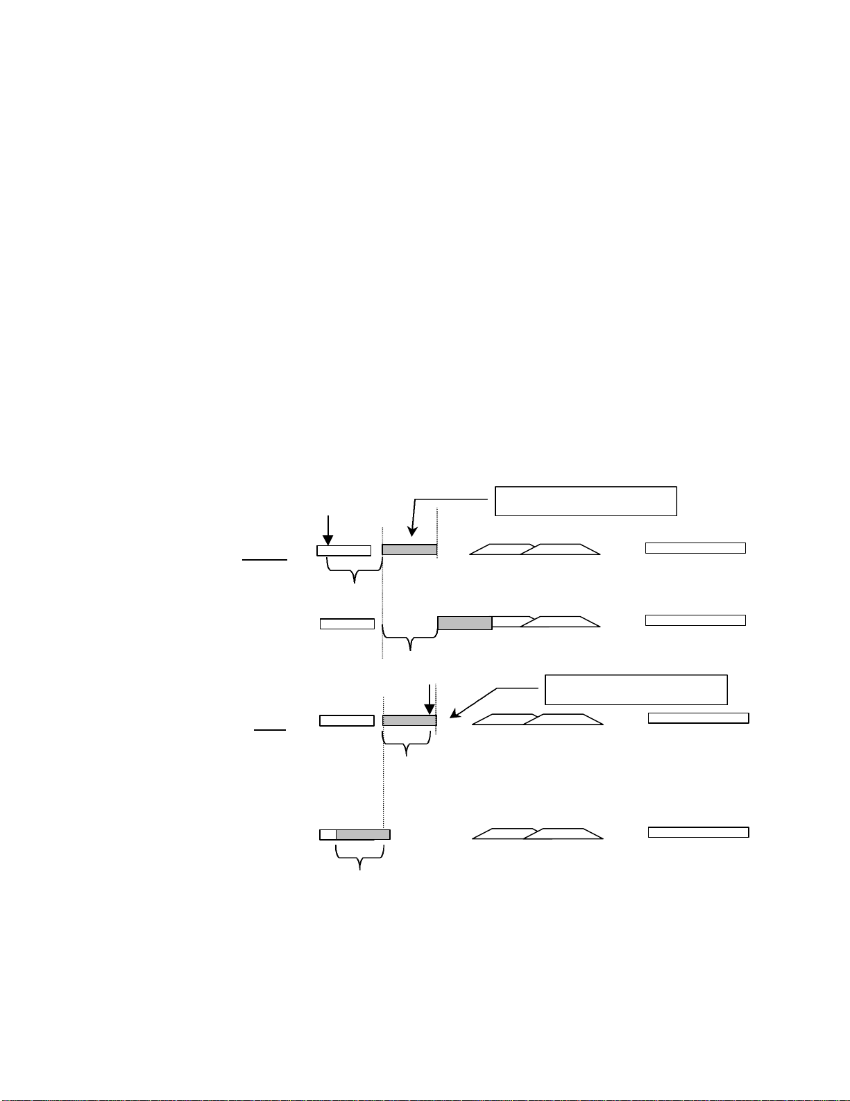
81
Edit Sync Mode The setting chosen in Setup Menu 221 - Edit Sync Mode – determines which point
Out
To Clipboard w/offset
offset
offset
Out
To Clipboard w/offset
offset
offset
in the audio material to be pasted or inserted from the clipboard will be used as the
sync reference point for the edit. This is a very important consideration, since the
end result of the edit operation may be very different depending on the current
setting of this menu parameter when the edit is performed.
The two parameters for this menu are Sync at In Point and Sync at Playhead.
When Sync at In Point is chosen as the Edit Sync Mode, the beginning of the
region placed in the clipboard (by executing a Copy, Clear, or Cut operation) will
be placed at the current In register time code setting when a Paste or Insert
operation is performed. This is the mode illustrated in the graphic representations
of the Edit functions shown on the previous pages of this manual.
When Sync at Playhead is chosen as the Edit Sync Mode, the location of the
playhead relative to the In register is remembered as an offset when the material is
placed on the clipboard (by executing a Copy, Clear, or Cut operation). That offset
point (rather than the beginning of the region defined in the clipboard) will be
placed at the current In register time code when a Paste or Insert operation is
performed. The region defined in the clipboard will be placed at the appropriate
location relative to the offset amount defined when the Cut, Copy, or Clear
operation was performed. The Playhead offset can be before or after the In point of
the material placed on the Clipboard. Here are two examples:
Playhead
In
Clear w/Playhead Before In
In
Paste with Sync at Playhead
Playhead
In
Clear w/Playhead After In
In
Paste with Sync at Playhead
This function is most often used to synchronize a point within an audio segment (for example the point of
the Doppler shift in a car drive by) to a specific time code point (the place where the car appears closest in
the shot).
MMP-16 TASCAM MMP-16 Owner’s Manual • Chapter 4 • MMP-16 Operation
Page 80

82
Local & Studio Monitoring
A front panel headphone jack allows the MMP-16 operator to locally monitor one or more tracks, right at
the front panel, without affecting the output signals. The rear panel mini-jack output on the PRX card is
designed for studio monitoring using a customer-supplied studio monitor amplifier and speaker. The
mini-jack level is not controlled by the front panel volume control, and the audio output of the mini-jack
always presents a mono sum mix of all tracks according to the track monitor selection chosen on the front
panel. Headphone and studio monitoring both follow the Input Monitor selection, so if a track is being
monitored and it is switched to Input Monitor, the audio change will be heard in the headphones and
studio.
Headphone Volume (LEVEL)
The headphone monitoring volume is set by the LEVEL control next to the headphone jack.
Headphone Jack (PHONES)
Even though the Headphone jack is a standard pro-size stereo headphone jack (phone-type), all track
monitoring is done in mono. Either low (8 ohms) or high impedance (600 ohms) headphones can be used.
HEADPHONE NOTE:
To prevent hearing damage, always turn the Headphone Level full off before putting on
the headphones and leave the Level at a low volume until at least one track has been
selected for monitoring.
The Lynx Bus
The Lynx bus allows control of the MMP via a TimeLine Lynx Keyboard Control Unit (KCU). Connect
the KCU to one of the Lynx bus connectors on the back of the MMP. It is not necessary to have a Lynx 2
module as part of the system, since the MMP behaves as a Lynx synchronizer itself when connected to a
KCU. Other Lynx modules may then be connected through the other Lynx bus connector and the entire
system (up to a limit of six devices) controlled from the KCU.
To setup the MMP to be controlled from a Lynx KCU, set menu 120 (Lynx Bus) to Slave/KCU and use
menu 121 (Lynx Address) to set a valid Lynx address (one not used by any other Lynx device controlled
form the KCU). Although normal transport and track arm functions may be controlled from a standard
KCU, there is a special version of the Lynx KCU software (version 900) which provides increased
support for special MMP functions.
The KCU 900 software provides the following features for controlling the MMP-16 and MMR-8:
• Transport Control
• Track Record Arm/Select (MMR-8 only)
• Slip Track/Region
• Undo/Redo
• Goto Prev/Next Edit
• Goto Head/Tail
• Clear/Paste
Note that No support is provided by the KCU 900 software for the Lynx System Supervisor Unit (SSU)
TASCAM MMP-16 Owner’s Manual • Chapter 4 • MMP-16 Operation MMP-16
Page 81

83
Transport Control
The Lynx KCU will recognize the MMP-16 unit and will control all of the normal transport functions of
the unit. Note that the KCU does not support reverse play of multiple MMP units. When using the Roll
Back key for reverse play, it is first necessary to solo a machine.
Track Record Arm/Select (MMR-8 Only)
To arm a track for record or to select a track for an edit or goto operation, press the Track key on the KCU
and then press the appropriate number key on the calculator keypad to select or arm the desired track. The
Slip operation, as well as goto Prev/Next edit, goto Head/Tail, and Clear/Paste will operate only on tracks
that have been selected in this manner. If one of these operations is attempted, but a track is not selected,
the KCU display will prompt you to select a track first.
Head/Tail
Hold CLR while pressing the Head or Tail key to set the current time to the beginning or end of the
material on the selected track(s). You may then play from that point, or store the value in the desired
timecode register (press STO then the appropriate key on the Calculator).
Slip Track/Region
The K900 KCU software has a Slip key in the place of the key previously labeled END PT in the Special
Functions section of the KCU. Pressing this key puts the KCU in a “Trim” mode to allow slipping the
selected material forward or backward in time. The selection is defined as all material located between the
In and Out timecode registers on tracks that have been armed/selected as described above (see Track
Record Arm/Select). Upon pressing Slip, the – and + keys will highlight and the Wheel will be in Trim
mode. Use the Wheel or keys to enter a trim value to indicate how far the selected region will be slipped.
To end the operation and complete the Slip, press either the Trim key or the Slip key. Note that slipping
material within a track will automatically overwrite any previous material on the selected track(s) at the
new location.
To slip an entire track, use the goto Head/Tail commands (Hold CLR while pressing the Head or Tail
key) to set the current time and then store the value in the appropriate register (press STO then the In or
Out key on the Calculator) before executing the Slip command. To slip a single edit in an EDL, use the
PREV and NEXT keys in a similar fashion to locate the beginning and end of the Edit on the desired track
and store the time value for the beginning and end of the edit region in the In and Out registers before
executing the Slip command.
Prev/Next
Hold CLR while pressing the PREV and NEXT keys to set the current time to the beginning or end of an
edited region on the desired track. You may then play from that point, or store the value in the desired
timecode register (press STO then the appropriate key on the Calculator).
Undo/Redo
Hold CLR while pressing the Undo or Redo key to undo or redo the previous edit operation. The MMP16 supports ten levels of Undo and Redo. The MMP display will indicate which level of Undo or Redo is
affected by the operation, up to the maximum or ten.
MMP-16 TASCAM MMP-16 Owner’s Manual • Chapter 4 • MMP-16 Operation
Page 82

84
Clear/Paste
Hold CLR while pressing the Clear or Paste keys to perform these edit operations on the selected
material. Clear will remove audio from the selected tracks between the In and Out times, replacing it with
silence and will place the material into the MMP clipboard memory. Paste will place the material from the
Clipboard memory at the time set in the In timecode register on the selected track.
TASCAM MMP-16 Owner’s Manual • Chapter 4 • MMP-16 Operation MMP-16
Page 83

85
The MMR Bus
The operation of multiple MMP-16s may be synchronized by using the supplied 15-pin sync cable to
connect the MMP units together via the MMR bus sync connection (the two 15-pin connectors on the
SYNC card). Since this bus is self-terminating, simply daisy chain all the MMP-16s together in any order.
The MMR bus supports four independent Sync Groups, so any machine on the MMR bus can be assigned
to any of the four groups at any time without changing the physical connections. Also, since the MMR
bus carries system-wide frame and sample references, no other connections are required between the
various MMP-16s to provide sample accurate synchronization lock between them.
Each MMR/MMP Sync Group on the MMR bus must have a Master MMR or MMP unit, with the rest of
the units in the Sync Group acting as Slaves to the Master unit. It is only necessary for the Master unit to
receive incoming synchronization signals from external sources (digital clock, video sync, SMPTE/EBU,
biphase, etc.) since the remaining units on the associated MMR bus Sync Group will slave only to the
Master unit. This allows up 100 units to work synchronously and sample accurately together as one large
machine without having to feed duplicate sync reference signals independently to each unit.
Once the units to be linked using the MMR bus have been physically connected via the MMR bus
connection, their transports can be operated together as one large system. There are several Setup menus
which are used to govern how each unit behaves within the system. These are described here.
Menu 110 (MMR Bus Request) allows each MMR/MMP to request to be Master, Slave, or off the MMR
bus altogether. Only one MMR/MMP per sync group can act as master. If multiple units are set to request
master status through this menu, the MMR Bus system will automatically choose the unit with the lowest
serial number among those making the request to be set as the master for the sync group. The appropriate
MAST or SLAVE LED will light on the front panel to show the unit’s status on the MMR bus.
Menu 111 (Ident Request) allows each unit to request an individual identity on the MMR bus. If no other
unit is requesting the same ID, the system will set the unit ID to the requested number and that number
will be displayed in the Ident window on the front panel of the MMP. If another unit has requested the
same ID, the system will resolve the conflict and automatically assign each unit a unique ID on the bus. If
an ID other than that requested is assigned due to a conflict, this field will not change, and the machine
will continue to request this ID whenever it is powered up or added to an MMR bus chain.
Menu 112 (Ident Assigned) is an information display only (data cannot be entered) that shows the
currently assigned identity for this unit on the MMR bus. This number may be different than the ID
requested if there is a conflict on the MMR bus and the system has assigned the unit a different ID.
To synchronize a slave unit to the master unit on the bus once the above settings are confirmed, place the
slave unit online (press the ONLINE key on the transport).
MMP-16 TASCAM MMP-16 Owner’s Manual • Chapter 4 • MMP-16 Operation
Page 84

86
Chapter 5 MMP-16 Setup Menus
The Setup State & the Setup Menus
Setup menus allows individual MMP-16 parameters to be changed, and if desired, saved to one of the ten
User settings files. Parameters can also be changed within the current session without saving them to a
specific User settings file. Changes made in this way are automatically stored in a system init file and will
still be remembered even if the MMP-16 is powered down and restarted.
To enter the Setup state, press SETUP. To exit the Setup state and return to the Normal state, press the
SETUP key again, or press CLR. While in the Setup state, a display of various Setup menus and their
parameters takes the place of the time code display shown in the LCD in the Normal state.
When the Setup state is activated for the first time after power-up, Setup menu 000 (the Control Mode
selection menu) is displayed in the LCD. The Setup menus are divided into ten banks, grouped according
to their common functions (see Table 4-1). Scroll through the various Setup menus by rotating the Wheel
or using the Up/Down arrow keys. Clockwise (CW) rotation or up-arrow incrementally scrolls upward
through the menus, while counterclockwise (CCW) rotation or down-arrow scrolls downward through the
menus. The scrolling wraps around at the end of the list (thus menu 990, the highest menu in the 900
bank, is displayed when the wheel is rotated CCW from menu 000, and vice versa). Jump directly to any
menu bank by pressing a numeric key while in Setup. For example, pressing 3 will jump the display to
menu 300 (Biphase Frame Rate), which is the first menu in the 300 bank.
BANK # BANK DESCRIPTION
000 Basic Setup (Control Mode, frame/sample reference, etc.)
100 Bus Control (sync group, MMR/Lynx bus, interlock)
200 Transport Control (Record modes, Loop modes, pre/post roll, etc.)
300 Biphase (pulse rate, motion limits, start/end limits)
400 Remote Control (parallel remote)
500 Audio parameters (input source, calibration, reference level & tone)
600 Digital I/O (format, delays, sample rate conversion & reference tracks)
700 Disk (formatting, cleanup, archive)
800 Tracks & Projects (project name, track prefix)
900 System (store/recall settings, date & time, LED brightness, serial #)
The Ten Setup Menu Banks
The JOG and SHTL (Shuttle) keys above the Wheel take on their alternate reversed text-labeled functions
(left and right arrows) when pressed during Setup. Note that these are not shifted functions, but alternate
functions that occur in the Setup or Track states. These keys typically affect window scrolling, but in
some cases move a cursor to different points in displayed information.
TASCAM MMP-16 Owner’s Manual • Chapter 5 • MMP-16 Setup Menus MMP-16
Page 85
87
When trimming is active (press TRIM), rotating the Wheel or pressing the Up/Down arrow keys scrolls
through the available selections for the current menu. These selections also usually “wrap around.” If the
menu requires a single numeric value, the wheel or arrow keys will increment or decrement the numeric
value, but it will not “wrap around” once the top or bottom of the range is reached. For character and time
code items, the left/right arrow keys usually control the position of the cursor (and therefore which
character or digit is changed), rather than horizontally scrolling the window.
Setup Operation
There are various types of Setup menu items, each with its own particular behavior. Many scroll through
a set of multiple-choice selections; others simply display information that cannot be altered, such as a
version or serial number. The top line of the LCD in Setup lists the menu number and name, while the
bottom line shows the current menu item value. Here’s a typical example:
01234567890123456789 LCD character positions (left to right)
000 Control Mode (Setup Menu Item number and name)
*Biphase Chase (The current parameter choice)
The asterisk (*) directly before the item value indicates that the displayed value is the currently selected
value.
To scroll through the parameters in a menu of this type, press the TRIM key (the LED above TRIM will
turn on) and then rotate the Wheel or press the up/down arrow keys. Each choice will be sequentially
displayed. Once the desired parameter is shown in the display, press STO (the Store key). This activates
that choice, placing an asterisk in the display, and exiting trim mode. At this point, rotating the Wheel or
pressing the arrow keys will again scroll through the menus. To stop scrolling through the parameter list
without saving any changes, press TRIM again. To exit Setup and return to the Normal state, press
SETUP or CLR. Exiting Setup does not save a value, but exits without changing the current menu item’s
value. Exceptions to this are the few menu items that update dynamically as they are changed, such as
LED brightness (menu 920).
The next pages provide a chart of all of the MMP-16 menus and the parameter choices for each menu
item. Following the chart, some of the menus and the parameter choices they present are discussed in
more detail.
MMP-16 TASCAM MMP-16 Owner’s Manual • Chapter 5 • MMP-16 Setup Menus
Page 86

88
Setup Menu Chart
This chart lists all of the Setup Menus and their parameters. Note that * indicates the default selection.
MENU # MENU NAME
000 Control Mode
001 Frame Reference
002 Sample Reference
003 Time Code Type
004 Sample Rate
006 Varispeed Rate 100% *
100 Sync Group
PARAMETERS
Local/MMR*
Time Code Chase
Biphase Chase
Serial Transport
Editor
Varispeed
Automatic*
Video
Automatic*
AES/EBU Input
Ext Wordclock
24/24
25/25
29.97/DF
29.97/NDF
30/DF
30/NDF*
42294 (44x23/25)
42336 (44x24/25)
44056 (44100-)
44100
44144 (44100+)
45938 (44x25/24)
45983 (44x25/23)
46034 (48x23/25)
46080 (48x24/25)
47952 (48000-)
48000*
48048 (48000+)
50000 (48x25/24)
50050 (48x25/23)
(range 88.5% to 104.3%)
1*
2
3
4
TASCAM MMP-16 Owner’s Manual • Chapter 5 • MMP-16 Setup Menus MMP-16
Page 87

89
MENU # MENU NAME
110 MMR Bus Request
111 Ident Request
112 Ident Assigned
120 Lynx Bus
121 Lynx Address
122 Lynx V500 Mode
PARAMETERS
Master
Off*
Slave
Auto Assign*
01
(Range 01-100)
01*
(Range 01–100 read-only display)
Off*
Slave/KCU
Master
1*
Range: 0 through 127
Off*
On
210 Loop Mode
211 Loop Record
212 Pre-Roll
213 Post-roll
220 Next/Prev Mode
221 Edit Sync Mode
250 Slip Commit
300 Biph Frame Rate 24 fps*
301 Biph Pulse Rate 2 ppf
302 Biphase Input
Play Repeatedly*
Play once and Cue
Play once and Stop
Repeat Record*
Record Once Only
Repeat w/Unload
00:00:05:00*
00:00:02:00*
Event*
Cue
Sync at In Point*
Sync at Playhead
All Tracks*
Track 1
[lists all tracks through Track 8 on MMR, 16 on
MMP]
Track N
25 fps
30 fps
4 ppf
10 ppf*
20 ppf
25 ppf
50 ppf
100 ppf
Biphase*
Tach + Dir
Tach + Inverse Dir
MMP-16 TASCAM MMP-16 Owner’s Manual • Chapter 5 • MMP-16 Setup Menus
Page 88

90
MENU # MENU NAME
400 Editor Device
404 Editor Chase
420 MIDI Device Id
510 Crossfade 10 ms*
520 Meter Ref Level -20 dBFS*
522 Clip LED on Play Off*
530 Reference Tone Off*
550 Remote Meter Source MMR Bus*
PARAMETERS
TASCAM MMR-8*
Sony PCM-7030
Sony BVU-950
Disabled *
Timecode
Biphase
74*
(Range 1 to 127)
Range: 0 through 100
Range: -15 through -24 dBFS
On
1kHz
Local
610 Digital Out Delay Internal*
Number of Samples (Range:1 through 255 Samples)
710 Disk Initialize Press STO
711 Disk Low Format Press STO
720 Disk Cleanup Press STO
790 Drives Mounted [shows list in format: 0,1,2,3,4,5,6]
800 Project Name MMR Project*
810 Track Prefix MMR Trk*
900 Store Settings User 1
[through]
User 10
901 Recall Settings Default
User 1
[through]
User 10
Previous
910 Set MM:DD:YY Date: __:__:__
911 Set HH:MM:SS Time: __:__:__
912 Change Password Press STO
920 LED Brightness 8*
Range: 0 through 15
TASCAM MMP-16 Owner’s Manual • Chapter 5 • MMP-16 Setup Menus MMP-16
Page 89

91
MENU # MENU NAME
940 Machine Name Unnamed machine*
950 IP Address 000.000.000.000
951 IP Netmask 255.255.255.255
952 IP Gateway 000.000.000.000
980 Serial Number Read – only display
990 Software Version Read – only display
995 Load Software Press STO key
PARAMETERS
MMP-16 TASCAM MMP-16 Owner’s Manual • Chapter 5 • MMP-16 Setup Menus
Page 90

92
000 Basic Setup
This menu bank has settings for the most fundamental settings governing how the MM series machine
responds to external clocks and control. The items in this bank are:
• Control Mode
• Frame Reference
• Sample Reference
• Timecode Type
• Sample Rate
• Varispeed Rate
000 Control Mode
The MMP-16 will always operate in one of six Control modes. The default Control mode, which is how
the MMP-16 starts up when the unit is first installed, is called the Local/Bus Control Mode.
To change the Control mode, select Setup menu 000 (press SETUP to display the Setup menus).
Whenever the MMP-16 is powered up, the first menu displayed will always be menu 000 (“Control
Mode”). Afterwards, the menu displayed when entering Setup mode is the last menu displayed. Once
Setup menu 000 (“Control Mode”) is displayed, press TRIM to change the Wheel and the Up/Down
arrow keys to scroll through the seven menu choices under Setup menu 000. Once the desired operating
mode is displayed, press STO (the Store key) to select that choice. This immediately switches the various
parameters to the new control mode, typically causing several LEDs to change status according to the
new parameters. To exit Setup mode, press SETUP or the CLR (Clear) key.
Following is a more detailed description of the six control modes that are supported by the MMP-16:
Local/Bus
In local mode (offline) the MMP-16 functions like other stand-alone digital playback devices. No external
sync signals are required. The front panel transport keys offer direct control over system audio playback.
When placed into bus (online) mode, the MMP-16 can function as either a master or a slave to other
MMR bus or Lynx bus devices, as set through Setup menu 110 (MMR Bus) and menu 120 (LYNX bus).
Time Code Chase
In Time Code Chase, the MMP-16 will slave to the time code coming from the time code input on the
rear panel when it is placed Online. In this mode the time code input must have valid time code in order
for the MMP-16 to chase, lock, and synchronize itself to the incoming time code. Pressing any of the
transport keys will take the MMP-16 off-line and allow local control at any time. Placing the MMP-16
back online will cause it to lock to and chase the selected time code once again.
Biphase Chase
In Biphase Chase, the MMP-16 chases, interlocks, and synchronizes to a biphase or tach/dir. signal on
one of the four Biphase Inputs (the active input is determined by the Sync Group number set in menu
100). The system locks and plays audio at speeds from 0 to 1.5 times play speed in both forward and
reverse directions. The MMP-16 can then serve as a master for other devices on the MMR or Lynx buses.
TASCAM MMP-16 Owner’s Manual • Chapter 5 • MMP-16 Setup Menus MMP-16
Page 91

93
Serial Transport
This mode allows the MMP-16 to control an external audio or video transport connected to the 9-pin
serial Transport connector. Video and audio decks using the P2 protocol can be controlled (including
models from Accom, Alesis, Ampex, Fostex, JVC, Otari, Panasonic, Sony, and TASCAM). When in
Serial Tran mode, the MM series unit will output transport commands to external serial devices through
the 9-pin serial Transport output using Sony P-2 protocol. The unit will then lock to the external serial
device via linear timecode coming from the device through the MM unit’s timecode input (not through
serial timecode).
Editor
Using the Editor connector (and Sony P2 protocol) a video editor or other non-Lynx synchronizer can
control the MMP-16 transport functions when the MMP-16 Control Mode is set to Editor. When in Editor
mode, the MM series unit will respond to transport and track arming commands coming in to the 9-pin
serial Editor port. This setting is typically used with traditional video edit controllers.
Varispeed
Varispeed mode allows for setting playback speed within a range of 87.5% to 112.5% of nominal play
speed. This range varies according to the sample rate selected. Varispeed varies the playback frequency as
well as the digital sample clock on the digital output.
Serial Editor Port Details
There are a number of important details to note about the Serial Editor port as noted below.
Record Ready Tallies
Record ready tallies issued over the 9-pin serial Editor port now include tracks armed at the MMR-8 front
panel or MM-RC, and not just those tracks armed by serial command. This allows an external Serial
device to know when a track has been armed for recording, regardless of the source of the track arm
command.
Sony P2 Chase and Offset Commands
Sony P-2 protocol Chase and Offset commands are accepted by the MMR/MMP. Setup Menu 404 allows
for setting the chase source to either Timecode, Biphase, or Disabled.
Serial Editor Port Active When Not ONLINE
The MMR/MMP unit will follow transport, track arm, and record commands given on the 9-pin serial
Editor port even when the unit is not ONLINE.
Automatic ONLINE
The MMR/MMP unit will automatically be placed in the ONLINE state when placed in Chase via the
serial 9-pin Editor port.
Local Machine Response to Serial Record Commands
Serial record arm and punch in/out commands are honored locally on each machine, regardless of whether
it is acting as an MMR Bus slave or master machine. These commands are not propagated across the
MMP-16 TASCAM MMP-16 Owner’s Manual • Chapter 5 • MMP-16 Setup Menus
Page 92

94
MMR Bus to other machines, and serve only to activate the machine to which the Serial control device is
directly connected.
Program Speed Play
The MMR/MMP responds in a very controlled way to Sony Program Speed Play commands. The status
response during Program Speed Play indicates Play mode, with the VAR bit set in byte 2 of the Sony
Status array.
Editor Mode Operation Without Video Reference
The Editor Control Mode (set via Setup Menu 000) will not force the Frame Reference (Setup Menu 001)
to Video, and will allow operation of the MMR/MMP without a valid video sync reference source
attached to the MMR/MMP. It is highly recommended to have such a source when operating in this
mode, and to set the Frame Reference Setup Menu to Video, but the system does not require it and will
allow operation even if no such source is detected. If the controlling device is synchronizing the
MMR/MMP via the serial Editor port, it is essential to provide a video reference to insure correct
operation and synchronization.
Hybrid Protocol on Serial Editor Port
The MMR/MMP internal communication protocol (TimeLine’s Hybrid Protocol) can be accessed via the
serial 9-pin Editor control port. This is most useful for companies which want to exercise remote control
(from some other device) of MMR/MMP features not supported via any of the other standard remote
interfaces. Requests for Hybrid Protocol information and documentation should be directed to the
Marketing Director at TimeLine Vista, Inc. at (760)761-4440, or via email request to:
TimeLine@digaudio.com.
001 Frame Reference
These settings determine the source of the MM unit’s video frame reference signal.
Automatic
Sets the unit to automatically use an internal video reference if no external reference is available. This is
the default value.
Video
When set to Video, the MM unit will reference the video signal coming into the Video In port on the back
of the machine.
002 Sample Reference
These settings determine the source of the MM series unit’s digital sample clock reference signal.
Automatic
Sets the unit to automatically use an internal word clock reference if no external reference is available.
This is the default value.
AES/EBU Input
When set to AES/EBU Input, the MM machine will reference the digital sample clock of the AES/EBU
signal coming in on the machine’s Digital In port.
TASCAM MMP-16 Owner’s Manual • Chapter 5 • MMP-16 Setup Menus MMP-16
Page 93

95
Ext Wordclock
When set to external word clock Input, the MM machine will reference the digital sample clock of the
external word clock signal coming in on the machine’s external word clock BNC connector.
003 Timecode Type
The following timecode types are provided as choices in this setting:
• 30ND (default)
• 30DF
• 25/25
• 24/24
• 29ND
• 29DF
004 Sample Rate
The following digital sample rates are provided as choices in this setting:
• 42294 (44x23/25)
• 42336 (44x24/25)
• 44056 (44100-)
• 44100
• 44144 (44100+)
• 45938 (44x25/24)
• 45983 (44x25/23)
• 46034 (48x23/25)
• 46080 (48x24/25)
• 47952 (4800-)
• 48000 (default)
• 48048 (4800+)
• 50000 (48x25/24)
• 50050 (48x25/23)
006 Varispeed Rate
This setting allows for setting a varispeed playback rate. This function allows playback of audio over a
range of speeds from 88.5% to 112.5% of nominal play speed. This range varies according to the sample
rate selected. Varispeed varies the playback frequency as well as the digital sample clock on the digital
output. The precise speed can be set from ViewNet in increments of .01% over the entire range.
This function works by changing the sampling rate of the unit and this is reflected in the sample rate of
the digital audio output stream from the MMR/MMP, which will vary according to the speed set in this
menu. This is different from the jog/shuttle mode because that mode produces a constant sample rate
output while scrubbing audio off speed. Note that the Varispeed Mode is mutually exclusive with
Timecode Chase or Biphase Chase and thus the unit cannot be synchronized to an external source while
in this mode.
The default value is 100%.
MMP-16 TASCAM MMP-16 Owner’s Manual • Chapter 5 • MMP-16 Setup Menus
Page 94

96
100 Bus Control
100 Sync Group
Sets the MMR Bus sync group assignment for the MM series unit. Default is 1.
110 MMR Bus Request
Sets the status request for the MM series unit on the MMR Bus.
§ Off The MM unit will not be active on the MMR Bus (default).
§ Slave The MM unit will request to be a Slave on the MMR Bus.
§ Master The MM Unit will request to be the Master on the MMR Bus.
111 Ident Request
Sets the unit ID (Ident) request for the MM series unit on a particular MMR Bus sync group. This value
can be any number between 00 and 99, or can be set to Auto. When Auto request is on, the system will
assign ID numbers based on when units become active on the bus and their unique serial numbers. The
recommended practice is to assign units to unique individual ID numbers and to avoid using the Auto
setting. If a conflict arises, the system will automatically resolve it and will not allow duplicate ID
numbers. Default is auto assign.
112 Ident Assigned
This setting shows the Ident assigned for the MM series unit on the MMR Bus. Since there can be no
duplicate ID numbers on the MMR Bus Sync Group, it is possible that some units will be assigned a
status other than that requested.
120 Lynx Bus
Sets the MM series unit’s status on the TimeLine Lynx bus.
§ Off The MM unit will not be active on the Lynx Bus (default).
§ Slave The MM unit will request to be a Slave on the Lynx Bus.
§ Master The MM Unit will request to be the Master on the Lynx Bus.
121 Lynx Bus Address
Sets the Lynx bus address for the selected MM series machine. The default is 1.
122 Lynx Bus V500 Mode
Sets the MM series machine to work with TimeLine Lynx V500 software. The default value is off.
TASCAM MMP-16 Owner’s Manual • Chapter 5 • MMP-16 Setup Menus MMP-16
Page 95

97
200 Transport
210 Loop Mode
Sets the behavior of the MM series machine when the Loop function is active. The choices for the setting
are:
§ Play Repeatedly Loops until the transport is stopped (default).
§ Play Once and Cue Plays once from pre-roll before In to post-roll after
Out then cues to pre-roll before In point and stops.
§ Play Once and Stop Plays once from pre-roll before In to post-roll after
Out then stops at end of post-roll.
211 Loop Record
Sets the behavior of the MM series machine during Loop Record operation. Choices are:
§ Repeat Record Loop Record until the transport is stopped (default).
§ Record Once Only Records once from In to Out then cues to pre-roll
before In point and stops.
§ Repeat w/Unload Record from In to Out then unloads track and records
new track. Loop record continues, creating a new track
with every loop until stopped.
212 Pre-roll
Sets the amount of time before the In point (called the pre-roll amount) used for loop play and record
functions. The default value is 00:00:05:00.
213 Post-roll
Sets the amount of time after the Out point (called the post-roll amount) used for loop play and record
functions. The default value is 00:00:02:00.
220 Next / Previous Mode
Sets which type of edit is used to determine the location of the next and previous edit points when
working with WaveFrame projects only. These edit points are used in the Go to Next or Go to Previous
edit commands in the transport control section of the ViewNet interface. The default value is Event.
§ Event Moves the playhead to the next or previous WaveFrame Event.
See the WaveFrame documentation for information on events.
§ Cue Moves the playhead to the next or previous WaveFrame Cue. See
the WaveFrame documentation for information on cues.
221 Edit Sync Mode
This setting affects where a clip will be pasted during an edit operation.
§ In point Sets the paste to place the beginning of the region stored in the
clipboard at the In point. (default value)
§ Playhead Sets the paste to place the contents of the clipboard to the selected
edit tracks in the same position relative to the Playhead as those
contents occupied when the material was placed on the clipboard.
MMP-16 TASCAM MMP-16 Owner’s Manual • Chapter 5 • MMP-16 Setup Menus
Page 96

98
250 Slip Commit
The Track Slip function on the MMR/MMP works by changing the value of a track offset register. This
slip offset is volatile and will be cleared when a new Project or track is loaded. When a track slip is
committed using this setting, the amount of the slip for the selected track(s) is incorporated into an edit
operation which changes the track EDL to reflect the new timecode location for all audio events on the
track. This change is automatically saved to disk for WaveFrame and Pro Tools projects (not for other
formats since they cannot be saved to disk) and the EDL is immediately updated.
The Slip Commit menu allows for committing all tracks which have a slip offset, or of choosing only a
specific track. The default value is to commit all track slips.
300 Biphase
These settings are used to control the behavior of the system while in Biphase Chase control mode.
300 Biphase Frame Rate
Sets the frame rate used when the system is in Biphase Chase mode. Frame Rate choices are:
§ 24 Frames per second (default value)
§ 25 Frames per second
§ 30 Frames per second
301 Biphase Pulse Rate
Sets the frame rate used when the system is in Biphase Chase mode. Frame Rate choices are:
§ 2 Pulses per frame (ppf)
§ 4 ppf
§ 10 ppf (default value)
§ 20 ppf
§ 25 ppf
§ 50 ppf
§ 100 ppf
302 Biphase Input
Sets the type of Biphase input signal required for operation in Biphase mode. Choices are:
§ Biphase Input (default value)
§ Tach and Direction
§ Tach and Inverse Direction
400 Remote
These settings are used to control the behavior of the system while being remotely controlled by other
devices or controllers.
400 Editor Device
Sets the Sony 9-pin control personality while in the Edit control mode.
TASCAM MMP-16 Owner’s Manual • Chapter 5 • MMP-16 Setup Menus MMP-16
Page 97

99
TASCAM MMR-8
This is the default setting. The TASCAM MMR-8 is the only setting which allows arming of all eight
digital tracks on the MMR. This is the default setting.
Sony PCM-7030
Emulates operation of a two-channel DAT machine. Only tracks one and two can be armed for recording
via the 9-pin port. All tracks can be armed locally or via the TASCAM MM-RC Remote Control Unit.
Sony BVU-950
Emulates operation of this ¾” video deck. Only tracks one and two can be armed for recording via the 9pin port. All tracks can be armed locally or via the TASCAM MM-RC Remote Control Unit.
404 Editor Chase
This allows for setting the only P-2 protocol chase source to either Timecode, Biphase, or Disabled. This
governs how the MM series unit responds to Sony 9-pin Chase and Offset commands. The default setting
is disabled.
420 MIDI Device ID
The sets the MM series unit’s MIDI device ID for use with MIDI machine control devices. The
MMR/MMP responds to MIDI Machine Control (MMC) messages received on the unit’s MIDI In port.
To set the MMC address, go to Setup Menu 420, press Trim and set the appropriate MIDI Device ID
number for as required by the device transmitting the MMC messages to which the MMR/MMP will
respond. The range of available MIDI device ID’s is 1 to 127, with the system default being 74.
500 Audio
These settings are used to control the behavior of the system audio functions.
510 Crossfade
This sets the crossfade amount used at punch in/out and edit points. The range is 0 to 100 ms in 1 ms
intervals. The default value is 10 ms.
520 Meter Reference Level
This sets the meter reference level in decibels for the front panel meters of the MM series unit. The
default value is –20dB.
522 Clip LED on Play
This setting determines whether or not the Clip LED on the MM-RC Remote Control Unit will illuminate
when clipping is detected on a playback track. The default value is off.
530 Reference Tone
This activates the internal 1kHz reference tone in the MM series unit. To hear the tone, the unit must be in
play. The default value is off.
MMP-16 TASCAM MMP-16 Owner’s Manual • Chapter 5 • MMP-16 Setup Menus
Page 98

100
550 Remote Meter Source
This sets the source of the signals sent to an MMU-16 meter bridge. The default setting is MMR Bus.
§ MMR Bus Signals are sent over the MMR bus and should go through an MM-RC remote before
being passed on to the MMU-16.
§ Local Signals are sent directly from the UIB port (remote control port) to an MMU-16 unit.
600 Digital I/O
610 Digital Output Delay
This sets an amount by which digital output signals will be delayed. The range for this setting is 1 to 255
samples in 1 sample increments. The default value is internal (no delay).
700 Disk
710 Disk Initialize
Initializes the disk as a WaveFrame drive.
711 Disk Low Format
Performs a low level format on the drive. The drive must be initialized for recording after low format.
720 Disk Cleanup
The Disk Cleanup function looks at all available project files (EDLs) on the SCSI volume defined in the
Target ID field and compares these to the audio files found on the disk. All unreferenced media files are
then deleted (cleaned up) to regain disk space. This is a direct command, not a setting. This function is
often used in conjunction with the Delete command found in the File Utilities window. After a project or
track is deleted, Cleanup can be used to delete the media that was referenced by the deleted EDL. A
warning prompt is shown if anything exists in the clipboard or undo list when a Disk Cleanup is
performed. This warning insures users will be aware that the clipboard will be emptied by the Disk
Cleanup process.
01234567890123456789 20 position LCD character positions
721 Disk Cleanup Top: (Menu Item)
OK to Clear Undo List? Bottom: (Warning Prompt)
To clear the clipboard and perform the Disk Cleanup, press STO. To cancel the Disk Cleanup operation,
press RCL (No). The LCD will then show the following message.
01234567890123456789 20 position LCD character positions
721 Disk Cleanup Top: (Menu Item)
No Files Deleted Bottom: (Message)
TASCAM MMP-16 Owner’s Manual • Chapter 5 • MMP-16 Setup Menus MMP-16
Page 99

101
790 Drives Mounted
This is an information display which shows the SCSI volume IDs of all mounted drives.
800 Tracks/Project
800 Project Name
This field is used to set the name for a new project. Once a new project name is applied, the existing
project will be unmounted and a new blank project with the project name indicated here will be created as
soon as some audio is recorded into one track of the project. The default name is MMR Project.
Another way to start a new project is to choose New project from the file menu. Using the New project
function also enters the project name into this field.
810 Track Prefix
This field is used to set the track prefix used for any newly created tracks. The default name is MMR Trk.
900 System
900 Store Settings
This menu allows for storing and recalling the current settings as a user settings file in the MMR-8 or
MMP-16. When using ViewNet to control the MM series machine, ViewNet settings files provide a better
way to create, save, and recall users settings. To save a customized setting, select Setup Menu 900 (press
SETUP, then the 9 key). Press the TRIM key, and rotate the Wheel or use the arrow keys to select the
User settings file number (1 - 10) desired. Press STO. This saves all of the current Setup parameters to
disk in the target User settings file. These settings are retained by the MMP-16, independently of even the
usual automatic-save, automatic-restore sequence, and may be recalled when desired.
901 Recall Settings
This menu allows for recalling any of the 10 user settings saved in the MM series machine. To recall a
previously stored User setting, select Setup Menu 901 (press SETUP, the 9 key, and rotate the Wheel CW
or use the arrow keys to locate menu 901, “Recall Settings”). Select the desired User settings file from the
list (press TRIM to change the Wheel and arrow key function to scroll through the Menu selections). It is
not possible to name the User settings files, nor is it possible to back them up to floppy disk or to restore
them to hard disk. It is possible to create and save named settings files using the ViewNet Audio
graphical interface. Note that Setup Menu 901 also allows the operator to select the last User setting that
was used (“Previous” option) as well as reset the MMP-16 to the factory defaults (“Default” option).
Most Control modes require that certain synchronization signals appear on one or more MMP-16 sync
inputs. If these signals are not present, the MMP-16 will fail to respond correctly. The following
configuration information is divided into the three main application areas of the MMP-16 (video, film,
and audio-only). Typical signal connections and Setup Menu selections are covered.
910 Set MM:DD:YY [Date]
This sets the date used by the system. Whenever a recording is made, the current date and time are used to
“time stamp” the recorded files.
MMP-16 TASCAM MMP-16 Owner’s Manual • Chapter 5 • MMP-16 Setup Menus
Page 100

102
911 Set HH:MM:SS [Time]
This sets the time used by the system. Whenever a recording is made, the current date and time are used
to “time stamp” the recorded files.
912 Change Password
Use this Menu to change the system password which protects user settings.
920 LED Brightness
The menu allows for setting the brightness of the LEDs on the front panel. The range is 0 – 18.
940 Machine Name
This field sets the name of the MM series machine. This information is stored as part of the system init
file on the hard disk of the MM machine. This name can also be set using the Machine Information
window available in the Machine menu. The machine name is shown in the Network and Project View
screens of ViewNet Audio.
950 IP Address
The IP (Internet Protocol) address for each machine must be entered manually at the front panel of the
MM series machine before that machine can be seen by the network and appear as a machine to the
ViewNet Audio software application. To set the IP address, press Setup on the front panel of the MMR,
and use the wheel or arrows to move to Setup menu 950.
Setting the IP Address
Enter the value for each of the four segments by using the wheel, up/down arrows, or by entering the
number on the keypad. To move to the previous or next segment (byte) of the address, press the left or
right arrow keys to move the cursor to that segment of the address. Use a leading 0 for two digit numbers.
Format of IP Addresses
The format of an IP address is 32 bits, divided into four bytes separated by periods. Each byte has eight
bits, so the maximum decimal numerical value of each of the four segments of the address is 255 (which,
starting at 0 gives a total of 256 or 28 values). IP addresses thus theoretically run from 000.000.000.000 to
255.255.255.255.
IP addressing is based on the concept of hosts and networks. A host is any device on the network that is
capable of receiving and transmitting IP data packets such as a personal computer, MM series machine
(which is also a computer), or a router. The hosts are connected by one or more networks. The IP address
of any host consists of its network address plus its own host address on the network.
951 IP Net Mask
Use this field to enter the IP Net mask. Set this value to 255.255.255.000 unless your network
administrator advises that you should use a different setting.
952 IP Gateway
Use this field to enter the IP Gateway if the ViewNet network is part of a larger network which uses a
Gateway. If there is no Gateway in use, there is no need to enter any data in this menu.
TASCAM MMP-16 Owner’s Manual • Chapter 5 • MMP-16 Setup Menus MMP-16
 Loading...