

Page 1
MC-DX32i
MICRO Hi-Fi SYSTEM
PC board shown are viewed from parts side.
The parts with no reference number or no parts number
in the exploded views are not supplied.
As regards the resistors and capacitors, refer to the
circuit diagrams contained in this manual.
!
Parts marked with this sign are safety critical
components. they must be replaced with identical
components - refer to the appropriate parts list and
ensure exact replacement.
Parts of [ ] mark can be used only with the version designated.
1 SAFETY INFORMATION
2 SPECIFICATIONS
3 ADJUSTMENT AND CHECKS
4 EXPLODED VIEW AND PARTS LIST
5 PC BOARDS AND PARTS LISTS
6 WIRING DIAGRAM
7 INCLUDED ACCESSORIES
2
3
4
6
10
20
22
Page 2
MC-DX32i
1 SAFETY INFORMATION
SAFETY INFORMATION
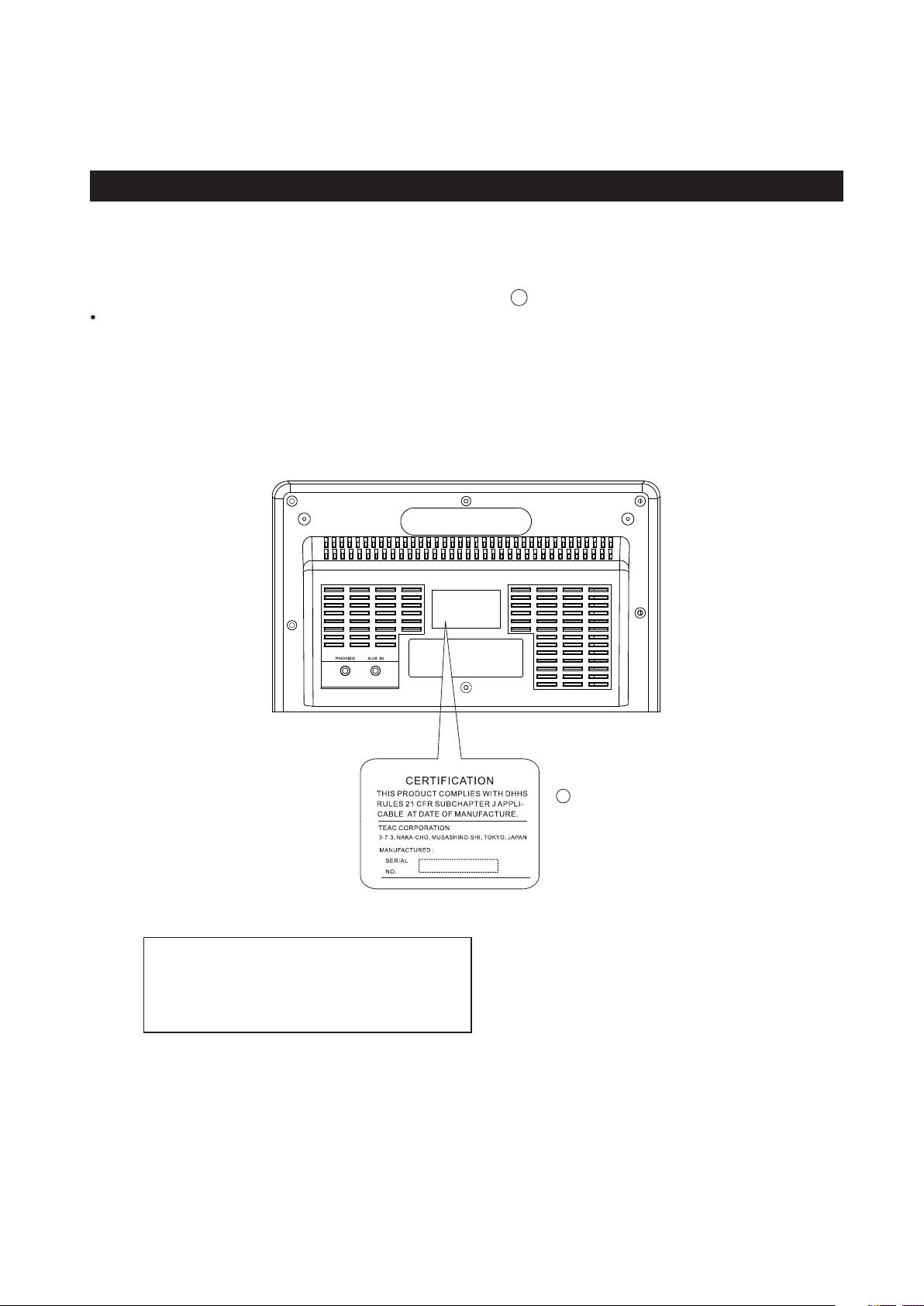
This product has been designed and manufactured according to FDA regulations " title 21, CFR, chapter 1,subchapter J,based on
The Radiation Control for Health and Safety Act of 1968" and is classified as class 1 laser product. There is not hazardous
invisible laser radiation during operation because invisible laser radiation emitted inside of this product is completely confined
in the protective housings. The label required in this regulation is shown .
CAUTION
USE OF CONTROLS OR ADJUSTMENT OR PERFORMANCE OF PROCEDURES OTHER THAN THOSE SPECIFIED HEREIN MAY
HAZARDOUS RADIATION EXPOSURE.RESULT IN
DO NOT REMOVE THE PROTECTIVE HOUSING USING SCREWDRIVER.
IF THIS PRODUCT DEVELOPS TROUBLE, MAKE A CONTACT WITH OUR SERICEMAN, AND DO NOT USE THE PRODUCT A TROUBLED
STATE.
1
1
FOR U. S.A.
Opt ical pi ckup:
Type : D A23Z1
Man ufact urer : SA NYO Ele ctric -Co., L td
Las er outp ut : Less t han 0.5 m W on the ob jecti ve lens
Wavelength : 765 - 815 nm
2
Page 3

2 SPECIFICATIONS
MC-DX32i
Amplifier Section
Output Power (L+R)
Output Power Subwoofer:
Input Sensitivity
Frequency Response :
Tuner Section (FM)
Frequency Range
Sensitivity (S/N30dB)
87.5 MHz to 108.0 MHz
Tuner Section (AM)
Frequency Range
Sensitivity (S/N20dB)
CD Player Section
Frequency Responce
Signa-to-Noise Ratio
Wow and Flutter
20 to 20,000 Hz (+/-1dB)
SPEAKER SYSTEM Section
L & R speaker :
Type :
Impedance :
Subwoofer:
Impedance :
5W + 5W
15 W
300mV
50 to 20,000 Hz
20dBuV
520 to 1710 kHz
54dBuV/m
55 dB
Unmeasurable
Full range flat type
4 ohms
8 ohms
Standard Accessories:
Remote control unit x 1
Battery for remote control unit x 1
Dock adaptor x 8
(adaptor “60GB(color)+ Photo 40GB/60GB” premounted)
Cover for the dock x 1
Subwoofer cable x 1
Speaker cable x 2
FM antenna x 1
AM antenna x 1
Stereo mini plug cable x 1
Wall mount brackets x 4
Screw (short) x 8
Screw (long) x 4
Tape plastic wall anchor x 4
Guide sheet for wall mounting x 2
Owner s manual x 1
Warranty card x 1
Quick guide for connection x 1
GENERAL
Power Requirements:
Power Consumption:
Dimension (W x H x D ):
Main Unit 255 x 169.5 x 115 mm
L & R Speaker 210x 169.5 x 81mm
Subwoofer 160 x 245 x 335mm
Weight: (net)
L & R Speaker 0.7 kg(each)
Design and specifications are subject to change without notice.
Illustrations may differ slightly from production models.
Weight and dimensions are approximate.
AC120V, 60 Hz
80 W
Main Unit 1.4 kg
Subwoofer 5.3 kg
3
Page 4
MC-DX32i
3 ADJUSTMENTS AND CHECKS
3-1 TUNER SECTION
Use a screwdriver with a plastic or ceramic grip for all adjustment.
3-1-1 FM adjustment
1. Set the function switch to the FM position.
2. Connect the signal generator output through a 75 ohm dummy
antenna to "ANT" on TUNER PCB.
3. Connect the oscilloscope to the speaker terminal.
4. Set the signal generator as listed in the alignment chart.
3-1-2 AM adjustment
1. Set the function switch to the AM position.
2. Connect the test loop antenna across the output of the signal generator.
3. Connect the oscilloscope to the speaker terminal.
4. Set the signal generator as listed in the alignment chart.
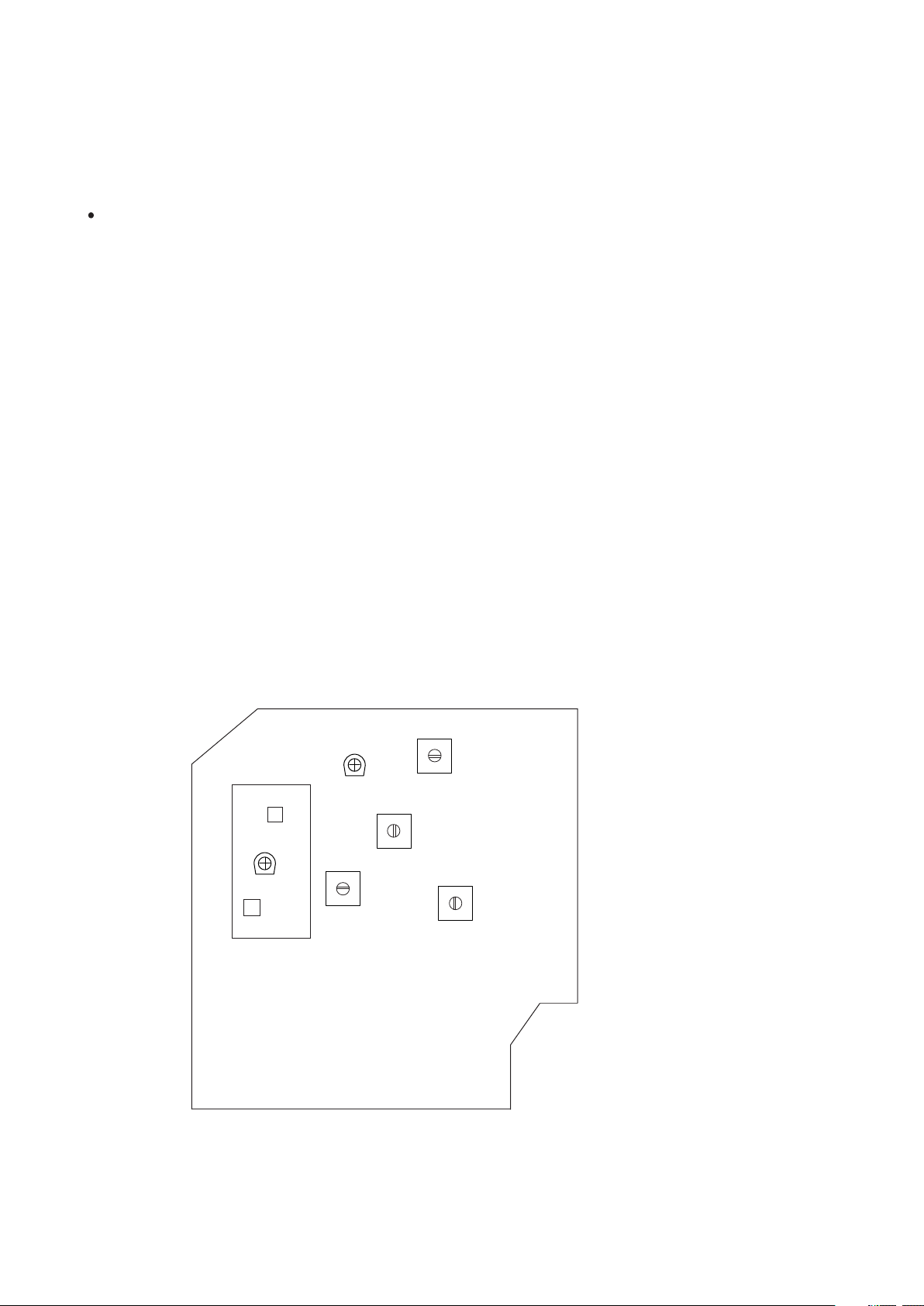
3-2 Adjustment and Test Points
SVC 202
TUNER
L202
SVC 201
T20 5
L201
T20 6
T20 4
T20 3
RADIO PCB
4
Page 5

3-2-1 FM/AM alignment chart
MC-DX32i
ITEM
FM
1.IFT adjustment
2. FM band
3. Tracking
AM
1. IF adjustment
SG SETTING
10.7 MHz
1kHz, +/-22.5kHz dev.
87.5MHz
1kHz, +/-22.5kHz dev.
90MHz
1kHz, +/-22.5kHz dev.
106MHz
1kHz, +/-22.5kHz dev.
Repeat step 3
450kHz
1kHz, 30% mod
TUN ER SETTING
108MHz
87.5MHz
90MHz
106MHz
1710kHz
ADJUS TMENT POINT
T205
L202
L201
SVC 201
T203
ADJUS TMENT
With 10.7 MHz at
zero crossover
Adjust for max. output
and best waveform.
Center for max. output.
2. AM band
3. Tracking
1kHz, 30% mod
1kHz, 30% mod
3-3 CD SECTION
Auto alignment.
520kHz
600kHz
1kHz, 30% mod
1400kHz
Repeat step 3
520kHz
600kHz
1400kHz
T206
T204
Adjust for max. output
and best waveform.
SVC 202
5
Page 6
MC-DX32i
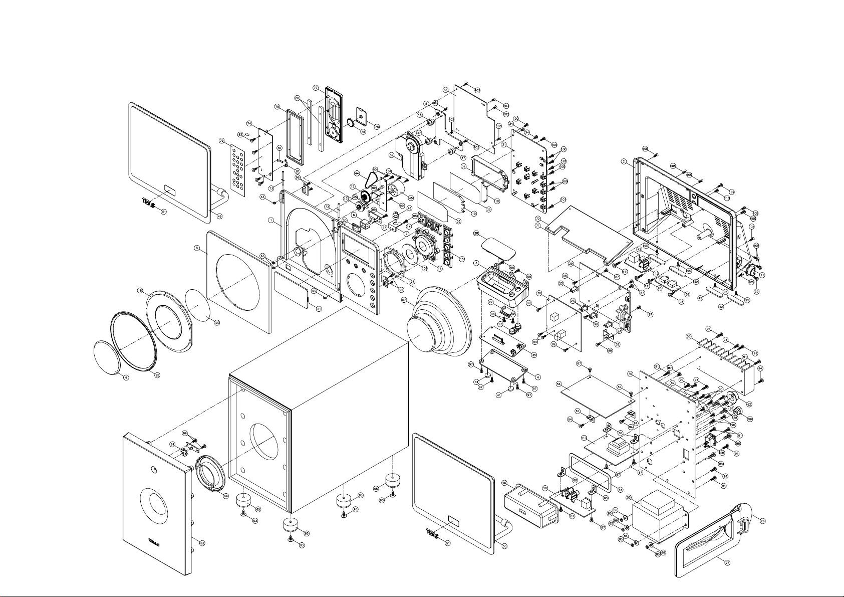
4. EXPLODED VIEWS AND PARTS
EXPLODED VIE
W
-1
6
Page 7

EXPLODED VIEW-1
REF. NO
1-1
1-2
1-3
1-4
1-5
PARTS NO.
56-04DX2200B030
56-05DX2200B010
56-07DX2200B010
56-07DX2201B000
56-07DX22039000
DESCRIPTION
FRONT CABINET
REAR CABINET
IPOD FRONT CABINET
IPOD BOTTOM CABINET
CD DESK BRACKET
MC-DX32i
REMARKS
1-6
1-7
1-8
1-9
1-10
1-11
1-12
1-13
1-14
1-15
1-16
1-17
1-18
1-19
1-20
1-21
1-22
1-23
1-24
1-25
1-26
1-27
1-28
1-29
1-30
56-07DX22I4B000
56-07DX22I5B000
56-14DX2200B000
61-68CD10I00020
56-22DX22I1B000
56-22DX22I2B000
56-24DX01500000
56-24DX01510000
56-54DX22I0A000
56-54DX22I1A010
56-54DX22I2A000
56-54DX22I3A010
56-57DX22I00000
56-57DX22010000
56-57DX22022000
56-57DX22030020
56-64DX22I0B000
56-67DX22009000
56-78DX22009000
56-78DX2202G000
56-07X20000B000
56-27X20000B000
56-22SRLXI0B000
05-01DX32I00000
05-02DX32I00001
REMOTE BRACKET
SHOCK ABSORBER BRACKET
CD DOOR
CD ALUM COVER
LED LEW COVER
PROTECT COVER
CD DOOR GEAR
STRAP GEAR
FUNCTION KNOB GROUP -1
FUNCTION KNOB GROUP -2
PLAY KNOB GROUP
IP VOL KNOB
CD DOOR LENS
BACKLIGHT LENS
REMOTE LENS
DISPLAY LENS
LATCH
PCB BRACKET
SHINE RING
CD DOOR RING
AM ANT STAND - BLACK
AM ANT HOLDER - BLACK
IPOD COVER - BLACK
MAIN PCB ASSY
RADIO PCB ASSY
1-31
1-32
1-33
1-34
1-35
1-36
1-37
1-38
1-39
1-40
05-04DX32I00001
56-07DX22029000
57-26DX22000020
66-140326180321
05-08DX32I00000
05-09DX32I00000
05-27DX32I00000
05-30DX32I00001
20-70DA23Z10000
56-760000000020
DISPLAY PCB ASSY
BACKLIGHT BRACKET
FILTER SHEET
SELF-TAPPING SCREW TA/PH2.6X8MM
IPOD SOCKET PCB ASSY
HP PCB ASSY
SENSOR PCB ASSY
CD PCB ASSY
CD MECHANISM
DOOR MOTOR PULLY
7
Page 8

MC-DX32i
EXPLODED VIEW-1
REF. NO
1-41
1-42
1-43
1-44
1-45
PARTS NO.
58-263102300120
58-26DX22000020
58-26DX220I0020
58-43DX01500020
58-44CD10I00020 DC MOTOR 5V
DESCRIPTION
RUBBER FOOT - BLACK
RUBBER FOOT W/TAPE
RUBBER RING DIA5.4X3X0.8MM
DRIVE BELT DIA31X1MM
REMARKS
1-46
1-47
1-48
1-49
1-50
1-51
1-52
1-53
1-54
1-55
1-56
1-57
1-58
1-59
1-60
1-61
1-62
1-63
1-64
1-65
1-66
1-67
1-68
1-69
1-70
58-61EX0M108120
58-61MC23500020
58-61MC23500120
19050DX220I0220
19050DX220I0320
56-58EXM5M0A000
61-11CDX0900020
!
18-203DX0150120
05-07DX32I00000
61-48DX01500020
05-08DX01500000
190021153300120
41-172111000310
43-500000002020
56-22DX0150B000
56-57CDX0936000
56-78CD10I0B000
56-85CD10I0B010
56-87CDX090B000
58-263253150020
58-73DX01500121
61-11V600000020
61-11V820010020
61-11DX01500321
61-33DX32I00021
SHOCK ABSORBER - GREY
SHOCK ABSORBER - GREY
SHOCK ABSORBER - BLACK
SPEAKER BOX UNIT-L
SPEAKER BOX UNIT-R
LOGO BADGE
DS METAL PLATE
H/TRANSFORMER EI66 120V/60HZ
SUBWOOFER POWER PCB ASSY
HEAT SINK - A
RCA/D-S JACK PCB ASSY
SPEAKER 8 OHM 30W
SWITCH #MR2-111-CM-BB3NW-V0
AC CORD BUSHING
PCB COVER
LIGHT LENS
SAFEGUARD RING/SUB
SUBWOOFER PANEL
PLASTIC TUBE
RUBBER FOOT DIA25MM
SUBWOOFER BOX
PCB BRACKET
PCB FIX BRACKET(B)
MOTOR BRACKET
SUBWOOFER REAR PANEL
1-71
1-72
1-73
1-74
1-75
1-76
1-77
1-78
1-79
1-80
61-11DX22000122
61-11DX22000222
61-80DX01500020
05-13CD10I00000
51-021301000080
56-43DX0150B010
56-43DX0151B010
56-44DX0150B010
57-33CD10I00020
61-11DX01500220
WEIGHT STEEL - 159X67.5X4MM
WEIGHT STEEL - 159X67.5X2MM
FERRUM SHAFT
REMOTE PCB ASSY
LITHIUM BATTERY CR2032
REMOTE FRONT CABINET
REMOTE REAR CABINET
REMOTE BATTERY DOOR
REMOTE PLATE
REMOTE AGGRAVATE FERRUM
8
Page 9

EXPLODED VIEW-1
REF. NO
1-81
1-82
1-83
1-84
1-85
PARTS NO.
61-25DX01500021
61-25DX01500120
66-140520170121
58-58DX01500320
67-021400000020
DESCRIPTION
BATTERY PLATE (+)
BATTERY PLATE (-)
SELF-TAPPING SCREW TA/KH2X7MM (BLK)
CUSHION 106X40X1MM
NUT M4MM
MC-DX32i
REMARKS
1-86
1-87
1-88
1-89
1-90
1-91
1-92
1-93
1-94
1-95
1-96
1-97
1-98
1-99
1-100
1-101
1-102
1-103
1-104
1-105
1-106
1-107
1-108
1-109
1-110
68-112403101000
66-120230160121
66-120240212121
66-140230210321
66-140230212121
66-140230214121
66-120330160321
66-141430212121
66-150230180123
66-120526210321
66-140220150121
66-140226212311
66-140230180321
66-140330180321
66-140330210321
66-140330212321
66-140330212121
66-140526180311
66-140226180321
66-140530212321
66-150530210321
57-08DX01500020
61-30DX22I00020
66-140230210121
66-140330180121
METAL WASHER 4X10X1MM
MACHINE SCREW MS/BH3X6MM (BLK)
MACHINE SCREW MS/BH4X12MM (BLK)
SELF-TAPPING TA/BH3X10MM
SELF-TAPPING TA/BH3X12MM (BLK)
SELF-TAPPING TA/BH3X14MM (BLK)
MACHINE SCREW MS/PH3X6MM
SCREW TA/BWH3X12MM (BLK)
HARDEN SCREW BTTB3X8MM (BLK)
MACHINE SCREW MS/KH2.6X10MM
SELF-TAPPING TA/BH2X5MM (BLK)
SELF-TAPPING TA/BH2.6X12MM (BLK)
SELF-TAPPING TA/BH3X8MM
SELF-TAPPING TA/PH3X8MM
SELF-TAPPING TA/PH3X10MM
SELF-TAPPING TA/PH3X12MM
SELF-TAPPING TA/PH3X14MM (BLK)
SELF-TAPPING TA/KH2.6X8MM
SELF-TAPPING TA/BH2.6X8MM
SELF-TAPPING TA/KH3X12MM (BLK)
SELF-TAPPING TB/KH3X10MM (BLK)
CD DOOR PVC PLATE DIA61.8MM
KNOB COVER
SELF-TAPPING SCREW TA/BH 3X10MM
SELF-TAPPING SCREW TA/KH 3X8MM (BLK)
(BLK)
1-111
1-112 05-11DX32I00000
1-113
66-141430216121
05-03DX32I00000
SCREW TA/BWH 3X16MM (BLK)
TV BOARD ASSY
STANDBY PCB ASSY
9
Page 10

MC-DX32i
MAIN PCB ASSY
REF. NO
CN2
CN203
CN501-503
PARTS NO.
05-01DX32I00000
48-01DX220I1220
43-022200120120
43-022250120221
43-022200130120
5 PC BOARDS AND PARTS LIST
DESCRIPTION
MAIN PCB ASSY
MAIN PCB
WAFER 2MM 2PIN
WAFER 2.5MM 2PIN
WAFER 2MM 3 PIN
REMARKS
CN504
CN506
CN508
CN511
CN-DC
D400,705
D601
D602,605,701-703
D603
IC501
IC703
JK201
L404,406
Q401
Q405,406,501,
Q502,705
Q701,707
Q703
Q704
Q706,715
Q712,713
Q716
ZD401
ZD501
ZD701
43-022200140120
43-012200130120
43-022200170120
43-022100212120
43-462103003321
12-1N4148000125
12-1N5819000121
12-1N40010000P1
12-SS1400000025
16-LC7534200021
16-SC1308000021
43-421000003120
38-013100050120
11-8050C0000025
11-PMBT39040021
11-9015C0000021
16-KA7808000221
11-KSB772YS0021
11-9014C0000025
11-8550C0000025
11-8050D0000025
12-011470320125
12-011680320125
12-012110320125
WAFER 2MM 4 PIN
WAFER 2MM 3 PIN
WAFER 2MM 7PIN
SMD F.F.C. WAFER 1MM 12 PIN
D-S TERMINAL #DSW-31
DIODE 1N4148
RECTIFIER DIODE 1N5819
DIODE 1N4001
CH-DIODE SS14
IC - LC75342
IC - SC1308-01
COAXIAL JACK IF-01A
AXIAL INDUCTOR 10UH #EC-24
TR - 8050C
SMD TR - PMBT3904
TR - 9015C
IC - KA7808E
TR - KSB772SY
TR - 9014C
TR - 8550C
TR - 8050D
ZENER DIODE 4.7V
ZENER DIODE 6.8V
ZENER DIODE 11V
TV PCB ASSY
REF. NO
CN900
S1
S2
10
PARTS NO.
05-11DX32I00000
48-11DX32I00220
43-012200140120
43-462103000120
43-451100014020
DESCRIPTION
TV PCB ASSY
TV PCB
WAFER 2MM 4P
D-STERMINAL #DS-15
RCA JACK 1P
REMARKS
Page 11

MAIN PCB
MC-DX32i
TV PCB
11
Page 12

MC-DX32i
RADIO PCB ASSY
REF. NO
CF201
CF203
CF205
PARTS NO.
05-02DX32I00001
48-02DX32I00220
31-028107000120
31-026450010110
31-038107020120
DESCRIPTION
RADIO PCB ASSY
TUNER PCB
CER.FILTER LT10.7MA5-A
CER.FILTER SFU450B
FILTER JT10.7MG46-A
REMARKS
CF206
CN201
CN202,206
CN512
D201,202
D204
IC201
IC202
L201,203
L202
Q201,206,207
Q202,203,209
Q204
Q208
SVC201
SV202
R241
T203
T204
T205
T206
VD201,202
VD203,204
31-046456000220
43-012250120120
43-012200120120
43-022150210120
12-1N41480000P1
12-1N4148000125
16-TA8176SN0021
16-LA1832000021
40-351500135020
40-351500125020
11-9018G0000021
11-KTC9014S0025
11-9014C0000025
16-LM78L0600021
27-501602202020
27-501602101020
38-013100050220
40-02A049004020
40-023120000020
40-027400003120
40-02660R002020
12-SVC101000021
12-SVC321SPA021
RESONATOR ZTB456F15
WAFER 2.5MM 2P
WAFER 2MM 2P
WAFER 1.5MM 10P
SMD DIODE 1N4148
DIODE 1N4148
IC - TA8176SN
IC - LA1832
FM COIL 5X3.5TX0.8MM
FM COIL 5X2.5TX0.8MM
TR - 9018G
SMD TR - KTC9014S
TR - 9014C
IC - LM78L06
TRIMMER 20PF
TRIMMER 10PF
AXIAL INDUCTOR 10UH #EC36
IFT 7MM A049 - YELLOW
IFT 7MM 312A - BLACK
IFT 7MM 740 - ORANGE
IFT 7MM 660R - RED
VARACTOR DIODE SVC101
VARACTOR DIODE SVC321
12
Page 13

RADIO PCB
MC-DX32i
13
Page 14

MC-DX32i
SUBWOOFER POWER PCB ASSY
REF. NO
CN1
CN2
CN3
PARTS NO.
05-07DX32I00000
48-07DX01500123
43-012250130120
43-012200190120
43-012200130120
DESCRIPTION
SUBWOOFER POWER PCB ASSY
SUBWOOFER POWER PCB
WAFER 2.5MM 3 PIN
WAFER 2MM 9 PIN
WAFER 2MM 3PIN
REMARKS
CN4
CN5
CN6
C406
C701
C718,719
D301,706
D401-404
D701-704
D705,707
FU2,3
FU4
Q301
Q707,708,710
U1
U2
U3
ZD1,2
43-012250150120
43-012250140120
43-012250120120
!
26-017470950111
!
26-017470850121
!
26-017100750121
12-1N4001000021
!
12-1N5401000021
!
12-RL2020000021
12-1N4148000021
!
46-055350200010
!
46-055400200010
11-9014C0000021
11-2SD1936T0021
16-TA8216H00021
16-BA4558N00021
16-BA5417000021
12-011910320121
RCA/D-S JACK PCB ASSY
REF. NO
CN801
SPK
PARTS NO.
05-08DX1500000
48-08DX01500221
43-462103003321
43-451200006120
WAFER 2.5MM 5 PIN
WAFER 2.5MM 4 PIN
WAFER 2.5MM 2 PIN
E.CAP - 4700UF/35V
E.CAP - 4700UF/25V
E.CAP - 1000UF/16V
RECTIFIER DIODE 1N4001
RECTIFIER DIODE 1N5401
RECTIFIER DIODE RL-202
DIODE 1N4148
GLASS FUSE 3.5A/125V
GLASS FUSE T4A/125V
TR - 9014C
TR - 2SD1936T
IC - TA8216H
IC - BA4558N
IC - BA5417
ZENER DIODE 9.1V
DESCRIPTION
RCA/D-S JACK PCB ASSY
RCA/D-S PCB
D-S TERMINAL #DSW-31
RCA JACK 2PIN - TC58-345-32
REMARKS
IPOD SOCKET PCB ASSY
REF. NO
D1-4
IC1
Q1,2
SW13,14
ZD1
14
PARTS NO.
05-08DX32I00000
05-08DX220I0323
12-1N41480000P1
16-LM324D000021
11-KTC9014S0025
41-150010050020
12-011510320125
DESCRIPTION
IPOD SOCKET PCB ASSY
IPOD PCB
SMD DIODE 1N4148
IC - SM LM324D
SMD TR - KTC9014S
TACT SWITCH 5MM
ZENER DIODE 5.1V
REMARKS
Page 15

SUBWOOFER POWER PCB
MC-DX32i
RCA/D-S JACK PCB
IPOD SOCKET PCB
15
Page 16

MC-DX32i
CD PCB ASSY
REF. NO
CN3
CN4,9,20,21
CN11
PARTS NO.
05-30DX32I00001
48-30DX32I00220
43-022100216220
43-022200120120
43-022200150120
DESCRIPTION
CD PCB ASSY
CD PCB
F.F.C WAFER 1MM 16PIN
WAFER 2MM 2 PIN
WAFER 2MM 5PIN
REMARKS
CN22
D7
H2
IC1
IC2
IC201
IC202
IC203
Q15
Q16
XT1
43-022200130120
12-1N5819000021
43-012150160320
16-TA7291S00021
16-KA7808000221
16-LA6541000121
16-LC78603E0021
16-LA9242M00021
11-2SB764E00021
11-8550D0000025
31-018169302220
STANDBY PCB ASSY
REF. NO
CN301
D309-313
FU1
Q302
Q303
RL301
T301
PARTS NO.
05-03DX32I00000
48-03DX01500123
43-012200130120
12-1N4001000021
!
46-074100300020
11-9014C0000021
16-LM78L0500121
46-50MC23000000
!
18-203DX32I0190
WAFER 2MM 3PIN
RECTIFIER DIODE 1N5819
WAFER 1.5MM 6PIN
IC - TA7291S
IC - KA7808E
IC - LA6541NHM
IC - LC78603E
IC - LA9242M
TR - 2SB764-E
TR - 8550D
CRYSTAL 16.9344MHZ
DESCRIPTION
STANDBY PCB ASSY
STANDBY PCB
WAFER 2MM 3PIN
RECTIFIER DIODE - 1N4001
SUBMINIATURE FUSE 100MA/250V
TR - 9014C
IC - LM78L05
RELAY ME-7-009
TRANSFORMER EI28 - HF-U28B39
REMARKS
SENSOR PCB ASSY
REF. NO
16
PARTS NO.
05-27DX32I00000
48-27DX220I0220
17-05FM60380012
DESCRIPTION
SENSOR PCB ASSY
SENSOR PCB
OPTIC SENSOR FM-6038TM2-5AN
REMARKS
Page 17

CD PCB
MC-DX32i
STANDBY PCB
SENSOR PCB
1
17
Page 18

MC-DX32i
DISPLAY PCB ASSY
REF. NO
CN1
CN2,5
CN6
PARTS NO.
05-04DX32I00001
48-04DX32I00120
43-022200120120
43-022200130120
43-022100212221
DESCRIPTION
DISPLAY PCB ASSY
DISPLAY PCB
WAFER 2MM 2P
WAFER 2MM 3P
WAFER 1MM 12P
REMARKS
D9
IC101
LCD
LED1,2
LED3-6
Q2,3
Q5
SW1-12
XT1
XT2
ZD2
12-1N4148000021
16-GY2980000021
13-05DX22I00020
13-011200121020
13-011206022020
11-KTC9014S0025
11-8550D0000025
41-150010050020
31-017450002010
31-015320003310
12-011270320125
HP PCB ASSY
REF. NO
L401-403,405
PARTS NO.
05-09DX32I00000
48-09DX220I0220
43-451360002020
43-431360003020
38-013100050120
OPEN SW PCB ASSY
REF. NO
PARTS NO.
48-23DX220I0220
41-071200010020
DIODE 1N4148
CPU - GY298
LCD DISPLAY #SDH-DA1292-TP- 1
LED D2X4MM - WHITE
LED D2X4MM - BLUE
SMD TR - KTC9014S-C
TR - 8550D
TACT SW 5MM
CRYSTAL 4.50MHZ
CRYSTAL 32.768KHZ
ZENER DIODE 2.7V
DESCRIPTION
HP PCB ASSY
HP PCB
PHONE JACK 3.6MM-TC38-060-01
PHONE JACK 3.6MM-TC38-063-05-01
AXIAL INDUCTOR 10UH
DESCRIPTION
OPEN SW PCB ASSY
SERIES MICRO SWITCH SD-007A
REMARKS
REMARKS
CLOSE SW PCB ASSY
REF. NO
PARTS NO.
48-23DX220I1220
41-071200010020
LED PCB ASSY
REF. NO
18
PARTS NO.
48-16DX01500221
13-011309022020
DESCRIPTION
CLOSE SW PCB ASSY
SERIES MICRO SWITCH SD-007A
DESCRIPTION
LED PCB ASSY
LED LAMP 3MM - ORANGE/BLUE
REMARKS
REMARKS
Page 19

DISPLAY PCB
MC-DX32i
HEADPHONE PCB
OPEN SW PCB
CLOSE SW PCB
LED PCB
19
Page 20

MC-DX32i
6 WIRING DIAGRAM
TO DISPLAY PCB
TO RADIO PCB
MAIN PCB
CN511
TO HP PCB CN507
CN206
CN204
TO RADIO PCB CN202
CN207
CN508
CN501
TO CD PCB CN2
TV PCB
CN503
CN502
TO IPOD PCB
TO HP PCB CN501A
TO IPOD PCB CN1
CN900
CN2
CN504
TO RADIO PCB
CN208
CN1
TO CD PCB CN1
20
Page 21

TO CD PICK UP
TO MOTOR
CD PCB
CN9
CN3
TO DISPLAY PCB CN8
CN4
MC-DX32i
TO OPEN SW PCB
TO DISPLAY PCB CN11
TO DISPLAY PCB CN9
CN21
CN22
CN11
H2
TO CD MOTOR
TO RCA/D-S JACK CN803
SUBWOOFER POWER PCB
CN6
CN5
CN4
CN2
CN1
TO RCA/D-S JACK PCB
CN802
T
O LED PCB
TO SPEAKER
TO TRANSFORMER
21
Page 22

MC-DX32i
7 INCLUDED ACCESSORIES
INCLUDED ACCESSORIES
REF. NO
PARTS NO.
77-20DX320I00020
45-194150000020
45-164300051120
45-164300151120
45-244300059120
DESCRIPTION
INSTRUCTION BOOK
FM ANT 1.5M - BLACK
SPEAKER CABLE - WHITE
SPEAKER CABLE - RED
9 PIN S TERMINAL CABLE - BLACK
REMARKS
45-263500000220
02-32DX01500000
51-021301000080
02-17DX32I00000
CONNECT CORD 3.5 ST/PLUGx2
AM LOOP ANT ASSY
LITHIUM BATTERY CR2032
REMOTE CONTROL
22
Page 23

MC-DX32i
TEAC CORPORATION
TEAC AMERICA, INC.
TEAC CANADA LTD.
TEAC MEXICO, S.A.De C.V.
TEAC UK LIMITED
TEAC EUROPE GmbH
TEAC ITALIANA S.p.A.
TEAC AUSTRALIA PTY., LTD.
A.B.N. 80 005 408 462
3-7-3 Nakacho, Musashino-shi, Tokyo 180-8550, Japan Phone:( 0422)52-5081
7733 Telegraph Ro ad, Montebello, California 90640 Phone: (323)726-0303
5939 Wallace Street, Mississauga, Ontario L4Z 1Z8, Canada Phone: (905)-890-8008
Campesinos N 184,Colonia.Granjas Esmeraida, Delega cion Iztapalapa,CP 09810,Mexico DF Phone: (525) -581-5500
Unit 19 & 20, The Cou rtyards, Hatters Lane, Wa tford, Hertfordshire, WD18 8TE5, U.K. Phone:(0845) 130-2511
Bahnstrasse 12, 65205 Wiesbaden-Erbenheim, Germany Phone: 0611-71580
Via C, Cantu 9/A, 2 0092 Cinisello Balsamo, Milano, Italy Phone: 02-66010550
280 William Street, Melbourne VIC 3000, Au stralia Phone:(03)9672-2400
C
MAY 2007
PREPARED IN HONG KONG
Page 24

MAIN PCB
1N5819
3904
3904
3904
K7808
MC-DX32i
Micro Hi-Fi System
Page 25

RADIO PCB
5x3.5T
SVC321
SVC321
1
5x3.5T
SVC101
5x2.5T
LM78L06
MC-DX32i
Micro Hi-Fi System
Page 26

SUB-WOOFER POWER PCB
U3
U2
U2
U1
D401-404
1N5401
1N4148
D701-704
RL-202
MC-DX32i
Micro Hi-Fi System
Page 27

CD PCB
CN3
CN11
MC-DX32i
Micro Hi-Fi System
Page 28

DISPLAY PCB
MC-DX32i
Micro Hi-Fi System
Page 29

IPOD SOCKET PCB
MC-DX32i
Micro Hi-Fi System
Page 30

STAND BY PCB
MC-DX32i
Micro Hi-Fi System
 Loading...