

Page 1
V-2U
OPERATING GUIDE
FOR
TYPES DA1-A,
DA2-A & DA3-A
DRAWN ARC PISTOLS
TAYLOR STUDWELDING
SYSTEMS LIMITED
A TAYLORMADE DRAWN ARC STUD WELDING PISTOL
Page 2

V-2U
INDEX
PAGE No. CONTENT
3 USEFUL INFORMATION.
5 IMPORTANT SAFETY INFORMATION.
7 INTRODUCTION TO STUDWELDING.
8 SETTING UP AND WELDING.
12 EXPLODED DIAGRAMS AND PARTS LISTINGS.
17 ACCESSORIES - STANDARD FOOT ASSEMBLIES.
19 ACCESSORIES - GAS FOOT ASSEMBLY.
20 ACCESSORIES - CHUCKS - EUROPEAN SCREW-ON TYPE.
21 ACCESSORIES - CHUCKS - EUROPEAN SCREW-ON GAS TYPE
UK TAPER FIT - ADJUSTABLE
22 ACCESSORIES - FERRULE GRIPS
BENDING BAR
23 EC DECLARATION OF CONFORMITY.
2
Page 3

V-2U
USEFUL INFORMATION
3
MANUFACTURERS DETAILS
TAYLOR STUDWELDING SYSTEMS LIMITED
COMMERCIAL ROAD
DEWSBURY
WEST YORKSHIRE
WF13 2BD
ENGLAND
TELEPHONE : +44 (0)1924 452123
FACSIMILE : +44 (0)1924 430059
email : sales@taylor-studwelding.com
WEB : www.taylor-studwelding.com
SALES DIRECT TEL : +44 (0)1924 487703
TECHNICAL HELPLINE : +44 (0)1924 487701
You may wish to record the details of your controller below as this informaon will help
with any technical assistance you may require:
PURPOSE AND CONTENT OF THIS GUIDE
This guide has been wrien for :
• The personnel of the end-user responsible for the installaon and maintenance of the
pistol.
• The operator of the welding pistol.
This guide contains informaon relang to :
• Installaon and connecon.
• Operaon.
• Technical specicaons and parameters.
• Spare parts.
PISTOL SERIAL No.
DATE PURCHASED.
Page 4
V-2U
USEFUL INFORMATION
4
FURTHER INFORMATION
Should you require addional technical informaon, please contact us directly (details
on previous page) or our local agent / distributor (details of agents etc. can be obtained
from us).
This guide contains important informaon which is a pre-requisite for safe Operaon
of the pistol. The operang personnel must be able to consult this guide when necessary. In
the interests of safety, make this guide available to your personnel in good me.
If the pistol is sold / passed on, please hand over this manual to the new owner and if
possible please inform us of the name and address of the new owner, in case we need to
contact him regarding the safety of the machine.
PLEASE READ THIS GUIDE CAREFULLY BEFORE INSTALLING OR OPERATING THE
PISTOL.
PLEASE OBSERVE CAREFULLY ALL SAFETY PROCEDURES/INSTRUCTIONS.
DUE TO THE POWER REQUIREMENTS AND ELECTROMAGNETIC EMISSIONS
PRODUCED DURING NORMAL USE, THIS PISTOL MUST ONLY BE OPERATED IN
AN INDUSTRIAL ENVIRONMENT.
NEVER REMOVE ANY PORTION OF THE UNIT HOUSING WITHOUT FIRST
ISOLATING THE PISTOL FROM THE CONTROLLER.
Taylor Studwelding Systems Limited reserves the right to amend the contents of this guide without nocaon.
Page 5

V-2U
IMPORTANT SAFETY INFORMATION !
5
PROTECT YOURSELF AND OTHERS !
Read and understand these safety notes.
1. ELECTRICAL
No poron of the outer cover of the welding pistol should be removed by anyone other
than suitably qualied personnel and never whilst mains power is connected.
ALWAYS DISCONNECT THE MAINS LEAD BEFORE ATTEMPTING ANY
MAINTENANCE.
BEWARE - RISK OF ELECTRIC SHOCK !
Do not use any uids to clean electrical components as these may penetrate into the
electrical system.
Installaon must be according to the seng up procedure detailed on page 8 of this guide
and must be in line with naonal, regional and local safety codes.
2. FIRE
During welding small parcles of very hot metal are expelled. Ensure that no combusble
materials can be ignited by these.
3. PERSONNEL SAFETY
Arc rays can burn your eyes and skin and noise can damage your hearing. Operators and
personnel working in close proximity must wear suitable eye, ear and body protecon.
Fumes and gases can seriously harm your health. Use the equipment only in a suitably
venlated area. If venlaon is inadequate, then appropriate fume extracon equipment
must be used.
Hot metal spaer can cause re and burns. Appropriate clothing must be worn. Clothing
made from, or soiled with, combusble materials must NOT be worn.
Have a re exnguisher nearby and know how to use it.
Magnec elds from high currents can aect heart pacemakers or other electronically
controlled medical devices. It is imperave that all personnel likely to come into the vicinity
of any welding plant are warned of the possible risks before entering the area.
4. MAINTENANCE
All cables must be inspected regularly to ensure that no danger exists from worn or
damaged insulaon or from unsound electrical connecons. Special note should be made
of the cables close to the pistol, where maximum wear occurs. As well as producing
inconsistent welds, worn cables can overheat or spark, giving rise to the risk of re.
Page 6

V-2U
IMPORTANT SAFETY INFORMATION !
6
5. TRAINING
Use of the equipment must be limited to authorised personnel only who must be suitably
trained and must have read and understood this manual. This manual must be made
available to all operators at all mes. Further copies of this manual may be purchased from
the manufacturer. Measures must be taken to prevent the use of this equipment by
unauthorised personnel.
6. INSTALLATION
Ensure that the site chosen for the equipment is able to support the weight of the
equipment and that it will not fall or cause a danger in the course of its normal operaon.
Do not hang connecng cables over sharp edges and do not install connecng cables near
heat sources or via trac routes where people may trip over them or they may be
damaged by the passage of vehicles (forklis etc).
7. INTERFERENCE
During welding operaons, intense magnec and electrical elds are unavoidably produced
which may interfere with other sensive Electronic equipment.
All Taylor Studwelding equipment is designed, manufactured and tested to conform the
current appropriate European standards and direcves regarding electromagnec
emissions and immunity and as such is safe to use in any normal environment.
8. DISPOSAL
The equipment either wholly or any of its component parts may be disposed of as part of
general industrial waste or passed to a scrap merchant. None of the components used in
the manufacture are toxic, carcinogenic or harmful to health in their “as supplied”
condion.
Page 7

V-2U
INTRODUCTION TO STUDWELDING
7
The Taylor Studwelding DA2-A studwelding pistol when matched with an appropriate
controller and earth cables is intended for precision stud welding up to 20 mm diameter full
base studs. The pistol is lightweight, ergonomic and has been designed to operate with a
minimum amount of maintenance.
The energy required to carry out the welding operaon is derived from an appropriate
studwelding controller.
Taylor Studwelding Systems Ltd controllers are modern, robustly designed and oer
maximum reliability combined with an easy to understand operator interface.
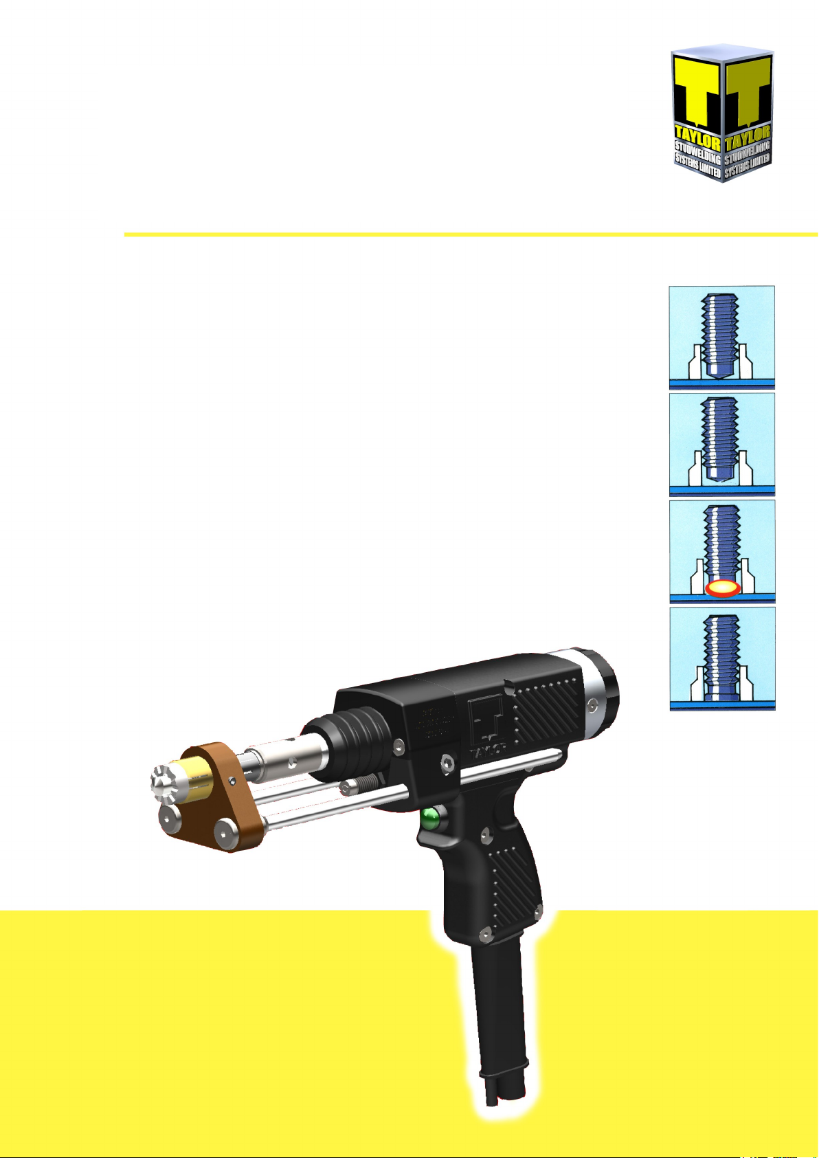
THE PROCESS
The process of drawn arc studwelding is long established and well proven. The basic steps
are as follows :
• A measured amount of weld stud protrusion is set at the welding pistol.
• Once in posion, the pistol lis the stud away from the work-piece, simultaneously
striking an arc between the two.
• Both the p of the weld stud and the surface of the work-piece melt as the arc is
sustained for a pre-determined interval.
• At the compleon of the pre-determined interval, the pistol returns the weld stud to
the molten pool on the work-piece, thus forming a weld.
The most common and tradional drawn arc welds have a weld duraon greater than
100ms and employ the use of a single use ceramic arc shield, commonly referred to as a
ferrule. This ferrule helps to protect the arc during the weld and assists in formaon of the
nal llet. Post welding the ferrule is removed and disposed of.
It is possible to stud weld without a ferrule. When using this method it is recommended
pracce to employ a suitable shielding gas to reduce the amount of porosity in the
completed weld and improve weld quality.
Page 8

V-2U
SETTING UP AND WELDING
8
As standard, the DA2-A pistol comes ed with standard
legs and a standard foot adaptor. The pistol has a standard
UK and American taper adaptor ed to the M10 thread on
the weld sha. This enables the use of standard UK tapered
DA chucks, enabling studs up to 20mm in diameter to be
welded (see g.1).
Other arrangements are available as shown in gs. 2 & 3.
In g.2 the adapter is not ed to the weld sha to
enabling standard European screw-on chucks to be used,
enabling studs up to 20mm in diameter to be welded.
In g.3 a 35mm gas foot arrangement using long legs and
an extended form of screw-on chuck allows for welding,
with or without gas.
Please refer to the accessories secon of this guide for
informaon regarding chucks and other accessories for the
pistol.
The DA2-A pistol is commonly referred to as a “ring li” pistol. This means the pistol has an
internal clutch, allowing for moderate inconsistencies in the length of the studs being
welded, without aecng weld quality.
1
2
3
Page 9

V-2U
SETTING UP AND WELDING
9
Once you have selected the type and size of
stud you wish to weld and obtained the
correct chuck (see the accessories secon of
this guide for a list of available sizes), you will
need to set up the chuck and t it to the pistol.
On the page “An introducon to studwelding”,
under the heading “The Process” it explains that a measured amount of stud protrusion is
set at the welding pistol.
To ensure that the correct amount of
protrusion will be available once the chuck is
ed to the pistol, it is important to set the
chuck correctly in the rst place. Some chucks
have a pre-determined depth (see right) which
will only allow a certain amount of the stud to
be inserted.
Other chucks have a backstop arrangement
that allows the depth of engagement to be
adjusted.
Regardless of which type of chuck is employed,
when welding with ceramic ferrules, it is
important that sucient stud length is
exposed to allow more than the “burn-o”
allowance of the stud to pass completely
through the ferrule. Insucient allowance may
result in the leading edge of the chuck hing
the back of the ferrule during welding. This
would result in failed welds.
In non-ferrule welding it is only necessary to
set the chuck so that sucient stud length is
exposed to prevent damage to the leading edge of the chuck during welding.
Having set up the chuck, you are now ready to t it into the pistol.
Page 10

V-2U
SETTING UP AND WELDING
10
Fit the chuck into the tapered sha
adaptor (g.1) and secure in place by
gently tapping the chuck to lock the taper.
The chuck may be subsequently removed
using a twist dri (see page 22 for tools)
inserted through the cross-drilled holes in
the taper adaptor.
Fit the ferrule grip into the foot adaptor
(g.2) and secure in place using the 2 set
screws in the foot adaptor. Do not overghten the set screws as this may result in
damage to either the ferrule grip or the
foot adaptor or both.
Place a stud and ferrule into the chuck
and grip (g.3). Ensure the stud is pressed
fully home and that the ferrule is properly
seated in the grip.
Centre the ferrule over the stud (g.4).
Use the 2 countersunk socket screws set
in the foot washers to loosen and adjust
the posion of the foot adaptor on the
pistol legs. It is very important that the
ferrule does not bind on the stud as this
will cause poor, inconsistent and failed
welds.
1
2
3
4
Page 11

V-2U
SETTING UP AND WELDING
11
Set the correct protrusion (g.5) by
loosening the two socket cap screws ed
at an angle in the sides of the front end
cap.
Slide the foot/leg assembly in/out (g.6)
to achieve the desired stud protrusion,
which should be around 2 - 4mm
depending on the diameter of stud being
welded. Protrusion is the distance from
the front face of the ferrule to the front
edge of the stud, not including the coned
p.
IMPORTANT! Please note that it is
necessary to check/reset the protrusion
when changing the stud length/diameter.
Adjustment of the pistol li is achieved by
turning the rear end cap of the pistol
(g.7). The cap has a “click” detent where
one “click” is approx’ equal to a 0.25mm
change in li. Turning the cap clockwise
(CW) will reduce li, whilst turning the
cap an-clockwise (ACW) will increase li.
Upon rst use when the li posion is
unknown, it is good pracce to zero the
pistol by turning the adjuster fully CW,
then in stages turning the adjuster ACW,
pulling the trigger between adjusts to observe the li, adjust unl the pistol begins to li. Once the
pistol begins to li, one click CW is the zero posion and the desired li can be set from this point.
PLEASE NOTE! It is possible to use
European type screw-on chucks with this
pistol. This is achieved by removing and
discarding the tapered chuck adaptor.
The adaptor can be removed by using a
pair of bars through the cross-drilled
holes in the adaptor and the front sha
adaptor (check under the rubber
protecon bellows for the sha hole).
Likewise the chuck is then ed (g.8) by
bracing the sha using this hole and an
appropriate wrench. It is IMPORTANT that the sha is properly braced when ng or removing
screw-on chucks. Failure to do so may result in damage to the pistol.
IMPORTANT! Informaon contained in this operang guide is intended to assist in seng up the
pistol. The suggested sengs are intended as a starng point only. Fine tuning the sengs to
achieve the most sasfactory results is essenal and is the responsibility of the user of the pistol.
5
6
7
8
2 - 4mm
Page 12

V-2U
EXPLODED DIAGRAMS & PARTS LISTINGS
12
ITEM QTY. PART No. DESCRIPTION
1 5½ 71-300-009 CONTROL CABLE
2 5 71-300-004 WELDING CABLE
3 1 71-101-030 CONTROL PLUG
4 1 81-101-051 WELDING PLUG
5 9 71-101-032 CABLE TIE (NOT SHOWN)
1 3
2 4
SEE PAGES 13 TO 16 FOR COMPLETE STAGED
BREAKDOWN OF PISTOL.
Page 13

V-2U
ITEM QTY PART No. DESCRIPTION
1 SEE PAGE 18 FOOT ASSEMBLY
2 SEE PAGE 18 CHUCK & GRIP
3 1 81-101-005 CHUCK GRIP
4 2 Z105-05-040 SCREW
5 1 81-101-298 BEARING BUSH
6 1 81-101-190 FRONT END CAP
7 1 81-101-297 A R PLATE
EXPLODED DIAGRAMS & PARTS LISTINGS
13
2
1
7 8 9
5 6
3 4
14 15
12 13
10 11
8 2 Z120-05-025 SCREW
9 2 81-101-191 LEG GRIP
10 2 Z100-05-025 SCREW
11 2 Z615-05-000 WASHER
12 1 81-111-044 BELLOWS
13 1 81-101-293 DAMPER
14 2 Z600-06-000 WASHER
15 2 Z105-06-010 SCREW
Page 14

V-2U
ITEM QTY PART No. DESCRIPTION
1 1 81-101-299 SHAFT SPRING
2 1 81-101-014 RING RET. PLATE
3 1 81-101-015 LIFTING RING
4 1 81-101-018 RING SPRING
5 1 81-101-286 LIFTING HOOK
6 4 Z100-04-008 SCREW
7 1 81-101-345 HOOK SPRING
8 1 Z120-06-016 SCREW
EXPLODED DIAGRAMS & PARTS LISTINGS
14
3 4 5
1 2
SEE BELOW FOR SHAFT
BREAKDOWN
6 7 8
COMPLETE SHAFT ASSEMBLY IS AVAILABLE UNDER PART No. : 81-101-134
13 14 15
11 12
9 10
17
16
ITEM QTY PART No. DESCRIPTION
9 1 81-101-192 SHAFT ADAPTOR
10 1 Z105-05-040 SCREW
11 1 81-101-194 INSULATOR
12 1 81-101-195 SHAFT BLOCK
13 1 81-101-197 INSULATOR
14 1 81-101-073 LIFTING SLEEVE
15 1 81-101-269 GUIDE ROD
16 1 81-101-193 INSULATOR
17 1 81-101-196 INSULATOR
Page 15

V-2U
ITEM QTY PART No. DESCRIPTION
1 2 Z100-04-016 SCREW
2 1 81-101-275 BODY (PART OF)
3 1 81-101-284 BODY RING
4 3 Z120-04-008 SCREW
5 1 81-101-285 REAR END CAP
6 2 Z120-05-012 SCREW
7 1 81-101-267 RETAINING RING
8 1 81-101-039 WASHER
9 2 Z650-05-016 PIN
EXPLODED DIAGRAMS & PARTS LISTINGS
15
1 2 3 4 5 6
12
10 11
8 9
7
18
16 17
14 15
13
ITEM QTY PART No. DESCRIPTION
10 3 Z400-03-008 SET SCREW
11 1 81-101-281 BACKSTOP
12 1 81-101-283 DETENT CAP
13 1 81-101-170 COIL
14 2 81-111-039 DETENT
15 2 Z400-04-012 SET SCREW
16 1 81-101-280 COIL HOUSING
17 1 81-101-282 BACKSTOP DRIVER
18 2 Z120-05-010 SCREW
Page 16

V-2U
1
2
3 4
5 6
7
8 9 10
11
12
13
14
EXPLODED DIAGRAMS & PARTS LISTINGS
ITEM QTY PART No. DESCRIPTION
1 1 81-101-275 BODY (PART OF)
2 1 81-101-288 FLEXI-BRAID
3 1 81-101-279 PUSHBUTTON
4 2 Z600-06-000 WASHER
5 2 Z615-06-000 WASHER
6 2 Z115-06-010 SCREW
7 3 Z120-05-020 SCREW
8 1 81-101-278 TERMINAL PLATE
9 1 Z800-04-026 PIN
10 1 Z600-04-000 WASHER
11 1 Z225-08-914 SCREW
12 1 81-101-275 BODY (PART OF)
13 1 Z700-06-S38 TERMINAL
14 1 81-101-287 CABLE SLEEVE
16
Page 17

V-2U
ACCESSORIES
17
SEE PAGES 20 - 22 FOR OUR STANDARD DRAWN ARC, EUROPEAN AND GAS CHUCKS,
FERRULE GRIPS AND ACCESSORIES RANGE
1 2
3 4
5 6 7 8 9
10 11 12
SEE NEXT PAGE FOR COMPLETE
FOOT ASSEMBLY PART NUMBERS
ITEM QTY. PART No. DESCRIPTION
1 2 Z400-05-008 GRUB SCREW
2 1 81-101-002 STANDARD FOOT ADAPTOR (M3 - M12)
3 2 81-101-004 STANDARD LEG (230mm)
4 2 89-101-081 EXTENDED LEG (330mm)
5 2 Z125-05-035 SCREW
6 2 81-101-003 FOOT WASHER
7 2 81-101-001 FOOT WASHER
8 1 81-101-063 STANDARD FOOT ADAPTOR (M16 - M20)
9 1 81-101-131 TRIPOD FOOT ADAPTOR (M16 - M20)
10 2 Z415-08-050 GRUB SCREW
11 2 Z510-08-000 LOCKNUT
12 1 81-101-126 TRIPOD FOOT ADAPTOR (M3 - M12)
Page 18

V-2U
ACCESSORIES
18
STANDARD FOOT ADAPTOR
ASSEMBLY (M3 - M12,
STANDARD LEGS)
COMPLETE ASSEMBLY :
81-101-158
STANDARD FOOT ADAPTOR
ASSEMBLY (M16 - M20,
STANDARD LEGS)
COMPLETE ASSEMBLY :
81-101-159
TRIPOD FOOT ADAPTOR
ASSEMBLY (M3 - M12,
STANDARD LEGS)
COMPLETE ASSEMBLY :
81-101-140
STANDARD FOOT ADAPTOR
ASSEMBLY (M16 - M20,
STANDARD LEGS)
COMPLETE ASSEMBLY :
81-101-141
Page 19

V-2U
ACCESSORIES
19
COMPLETE ASSEMBLY (NO LEGS)
PART NUMBER : 89-101-414
1 2 3 4 5 6 7 8 9
ITEM QTY. PART No. DESCRIPTION
1 1 89-101-249 Ø35mm NOSE CONE
2 3 Z400-05-006 GRUB SCREW
3 1 89-101-246 GAS CONE
4 1 89-101-245 FOOT ADAPTOR
5 1 PFS-P06-U1M-INT GAS FITTING
6 1 89-101-244 BELLOWS
7 2 Z400-05-010 GRUB SCREW
8 5.5 71-200-043 GAS PIPE
9 1 71-200-067 GAS PLUG
Page 20

V-2U
ACCESSORIES - CHUCKS
EUROPEAN SCREW-ON TYPE
20
Ø D PART NUMBER
3 5 89-101-003
4 5 89-101-004
5 6 89-101-005
6 7 89-101-006
8 9 89-101-008
10 11 89-101-010
12 13 89-101-012
Ø D PART NUMBER
4 25 89-101-021
6 15 89-101-022
6 25 89-101-023
8 6 89-101-024
8 25 89-101-025
10 4 89-101-026
10 6 89-101-027
12 6 89-101-028
TABLE 1 TABLE 1
LISTS OUR STANDARD STOCK RANGE OF CHUCKS.
TABLE 2 TABLE 2
LISTS OUR NON STOCK RANGE OF CHUCKS.
NOTE! NON STOCK CHUCKS WILL REQUIRE ADDITIONAL
DELIVERY LEAD TIMES AND MAY BE SUBJECT TO
MINIMUM ORDER QUANTITY.
PLEASE NOTE.
IF THE CHUCK THAT YOU REQUIRE IS NOT SHOWN HERE,
PLEASE CHECK WITH US.
Page 21

V-2U
ACCESSORIES - CHUCKS
UK TAPER FIT - ADJUSTABLE
ACCESSORIES - CHUCKS
EUROPEAN SCREW-ON GAS TYPE
21
Ø D PART NUMBER
5 4 89-101-035
6 4 89-101-036
6 7 89-101-037
8 4 89-101-038
8 9 89-101-039
10 11 89-101-040
12 13 89-101-042
Ø PART NUMBER
M3 89-101-203
M4 89-101-204
M5 89-101-205
M6 89-101-206
M8 89-101-208
M10 89-101-210
M12 89-101-212
M16 89-101-216
M20 89-101-220
PLEASE NOTE. OTHER CHUCK SIZES ARE AVAILABLE.
PLEASE CHECK WITH US IF THE SIZE YOU WANT IS NOT
LISTED HERE.
ACCESSORIES - CHUCKS
UK TAPER FIT - RECTANGULAR
SIZE PART NUMBER
6 x 30mm 89-101-203
6 x 19mm 89-101-204
3 x 16mm 89-101-205
PLEASE NOTE. OTHER CHUCK SIZES ARE AVAILABLE.
PLEASE CHECK WITH US IF THE SIZE YOU WANT IS NOT
LISTED HERE.
Page 22

V-2U
ACCESSORIES - BENDING BAR & TOOLS
ACCESSORIES - FERRULE GRIPS
22
Ø PART NUMBER
M3 89-101-051
M4 89-101-051
M5 89-101-052
M6 89-101-052
M8 89-101-053
M10 89-101-054
M12 89-101-055
M16 89-101-056
M20 89-101-057
ITEM PART NUMBER
BENDING BAR 79-101-121
M3 NOZZLE 79-101-123
M4 NOZZLE 79-101-124
M5 NOZZLE 79-101-125
M6 NOZZLE 79-101-126
M8 NOZZLE 79-101-127
M10 NOZZLE 79-101-128
COMPLETE SET 79-101-120
TOOL PART No.
KEY SET (2, 2.5, 3, 4, 5, 6, 8) 98-100-003
UK CHUCK EJECTOR TOOL
(TWIST DRIFT)
98-100-001
17mm A/F CHUCK SPANNER 98-100-006
Page 23

V-2U
TAYLOR STUDWELDING SYSTEMS LIMITED
COMMERCIAL ROAD
DEWSBURY
WEST YORKSHIRE TEL : +44 (0)1924 452123
ENGLAND FAX : +44 (0)1924 430059
WF13 2BD EMAIL : sales@taylor-studwelding.com
This is to cerfy that the machinery listed below is designed and manufactured in conformance
with all applicable health and safety regulaons.
This statement is invalid if any modicaons are carried out on the machinery without the prior
wrien approval of Taylor Studwelding Systems Ltd.
————————————————————————————————
DESCRIPTION OF MACHINE : Drawn Arc Studwelding Pistol
TYPE : DA1-A DA2-A DA3-A
PART NUMBER : 99-101-051 99-101-052 99-101-053
————————————————————————————————
Applicable EC direcves and corresponding standards:
- Low voltage direcve 2006/95/EC:
EN60204-1 Safety of machinery - Electrical equipment of machines.
- EMC direcve 2004/108/EC (electromagnec compability):
EN50081 Electromagnec compability - Generic emission standard
EN50082 Electromagnec compability - Generic immunity standard
EN50199 Electromagnec compability (EMC) Product standard for
Arc welding equipment
- Machine guidelines 2006/42/EC:
EN60974-1 Arc welding equipment : Electromagnec compability (EMC)
EC DECLARATION
SIGNED
DAVID TAYLOR
MANAGING DIRECTOR
 Loading...