

Page 1

Slush Freezer
Model C903
Operating Instructions
057072--M
6/10/04
Page 2

Complete this page for quick reference when service is required:
Taylor Distributor:
Address:
Phone:
Service:
Parts:
Date of Installation:
Information found on the data label:
Model Number:
Serial Number:
Electrical Specs: Voltage Cycle
Phase
Maximum Fuse Size: A
Minimum Wire Ampacity: A
EApril, 2004 Taylor
All rights reserved.
057072--M
Tayl o r
The word T aylor and the Crown design
are registered trademarks in the United States
of America and certain other countries.
a division of Carrier Commercial Refrigeration, Inc.
750 N. Blackhawk Blvd.
Rockton, IL 61072
Page 3

Table of Contents
Section 1 To the Installer 1............................................
Air Cooled Units 1.......................................................
Water Connections 1....................................................
Electrical Connections 1.................................................
Section 2 To the Operator 2...........................................
Compressor Warranty Disclaimer 2.......................................
Section 3 Safety 3....................................................
Section 4 Operator Parts Identification 4...............................
Beater Bowl Assembly 5.................................................
Mix Cabinet Assembly - Standard 6.......................................
Mix Cabinet Assembly - KanPak 7........................................
Mix Cabinet Assembly - Optional 8........................................
Peristaltic Pump Tube Replacement 9.....................................
Accessories 10..........................................................
Section 5 Important: To the Operator 11.................................
Power Switch 11.........................................................
Viscosity Adjustment 11...................................................
Display 12..............................................................
Keypad 12..............................................................
Flavor Lights 12.........................................................
Audio Alarm 12..........................................................
Passcodes 12...........................................................
Power Up Initialization Screens 12.........................................
Operator Menus 13......................................................
Bowl Modes 29..........................................................
Cleaning Lockout 31.....................................................
Section 6 Operating Procedures 34.....................................
Assembly 34............................................................
Sanitizing 36............................................................
Installing the Mix Tanks ( Non Bag-In-Box Product Only) 39....................
Installing the Syrup Bag-in-Box (B.I.B. Product Only) 40......................
Ratio Products (Products Requiring Water Added) 42.........................
Priming 43..............................................................
Table of Contents Model C903
Page 4

Table of Contents - Page 2
Cleaning Procedure 43...................................................
Rinsing 43..............................................................
Disassembly 46..........................................................
Brush Cleaning 47.......................................................
Daily Opening and Closing Procedures 49..................................
Section 7 Important: Operator Checklist 50..............................
During Cleaning and Sanitizing 50.........................................
Troubleshooting Bacterial Count: 50........................................
Regular M a intenance Checks: 50..........................................
Shipping / Winter Storage 50..............................................
Section 8 Troubleshooting Guide 51....................................
Section 9 Parts Replacement Schedule 52...............................
Section 10 Parts List 53.................................................
Wiring Diagrams 64......................................................
Note: Contin u ing research results in steady improvements; therefore, information
in this manual is subject to change without notice.
Model C903 Table of Contents
Page 5
Section 1 To the Installer
This machine is designed for indoor use only.
DO NOT installthemachineinanarea
where a water jet could be used. Failure to follow
this instruction may result in serious electrical shock.
Air Cooled Units
Air cooled units require a minimum air clearance of
3” (76 mm) in the back and 12” (305 mm) on the top.
This is required to allow for adequate air flow across
the condensers. Failure to allow adequate clearance
can reduce the refrigeration capacity of the freezer
and possibly cause permanent damage to the
compressor.
Water Connections
An adequate cold water supply must be provided
with a hand shut-off valve. On the back of the unit, a
1/4” male flare water connection has been provided
for easy hook-up. A flexible line is recommended, if
local codes permit. A minimum of 25 psi water
pressure is required to avoid a low water pressure
alarm. A booster pump must be provided if this
pressure is not available. It is always a good practice
to have a filter system to improve the quality of the
water and to avoid clogging the operating
components.
Note: Water lines beyond 200 ft. (61 m) require 1/2”
(13 mm) water lines.
INSTALL POTABLE WATER CONNECTION
WITH ADEQUATE BACK-FLOW
PROTECTION TO COMPLY WITH
APPLICABLE NATIONAL, STATE AND
LOCAL CODES.
Electrical Connections
CAUTION: THIS EQUIPMENT MUST BE
PROPERLY GROUNDED. FAILURE TO DO SO
CAN RESULT IN SEVERE PERSONAL INJURY
FROM ELECTRICAL SHOCK.
This unit must be plugged into a properly grounded
receptacle. A dedicated circuit is recommended,
sized for 15A usage. The standard voltage specification is 115V-60-1, however other electrical specifications may be available. Follow the specifications
listed on your data label.
In the United States, this equipment is intended to
be installed in accordance with the National
Electrical Code (NEC), ANSI/NFPA 70-1987. The
purpose of the NEC code is the practical
safeguarding of persons and property from hazards
arising from the use of electricity. This code contains
provisions considered necessary for safety.
Compliance therewith and proper maintenance will
result in an installation essentially free from hazard!
In all other areas of the world, equipment should be
installed in accordance with the existing local codes.
Please contact your local authorities.
Stationary appliances which are not equipped with a
power cord and a plug or other device to disconnect
the appliance from the power source must have an
all-pole disconnecting device with a contact gap of at
least 3 mm installed in the external installation.
FOLLOW YOUR LOCAL ELECTRICAL CODES!
050902
Model C903 To the Installer
1
Page 6

Section 2 To the Operator
The freezer you have purchased has been carefully
engineered and manufactured to give you
dependable operation. The Taylor Model C903,
when properly operated and cared for, will produce a
consistent quality product. Like all mechanical
products, they will require cleaning and
maintenance. A minimum amount of care and
attention is necessary if the operating procedures
outlined in this manual are followed closely.
This Operator’s Manual should be read before
operating or performing any maintenance on your
equipment.
Your Taylor freezer will NOT eventually compensate
for and correct any errors during the set-up or filling
operations. Thus, the initial assembly and priming
procedures are of extreme importance. It is strongly
recommended that personnel responsible for the
equipment’s operation, both assembly and
disassembly, sit down together and go through
these procedures in order to be properly trained and
to make sure that no misunderstandings exist.
In the event you should require technical assistance,
please contact your local authorized Taylor
Distributor.
Note: Constant research results in steady
improvements; therefore, information in this
manual is subject to change without notice.
If the crossed out wheeled bin symbol is
affixed to this product, it signifies that this product is
compliant with the EU Directive as well as other
similar legislation in effect after August 13, 2005.
Therefore, it must be collected separately after its
use is completed, and cannot be disposed as
unsorted municipal waste.
The user is responsible for returning the product to
the appropriate collection facility, as specified by
your local code.
For additional information regarding applicable local
laws, please contact the municipal facility and/or
local distributor.
Compressor Warranty Disclaimer
The refrigeration compressor(s) on this machine are
warranted for the term indicated on the warranty
card accompanying this machine. However, due to
the Montreal Protocol and the U.S. Clean Air Act
Amendments of 1990, many new refrigerants are
being tested and developed, thus seeking their way
into the service industry. Some of these new
refrigerants are being advertised as drop-in
replacements for numerous applications. It should
be noted that, in the event of ordinary service to this
machine’s refrigeration system, only the refrigerant
specified on the affixed data label should be
used. The unauthorized use of alternate refrigerants
will void your compressor warranty. It will be the
owner’s responsibility to make this fact known to any
technician he employs.
It should also be noted that Taylor does not warrant
the refrigerant used in its equipment. For example, if
the refrigerant is lost during the course of ordinary
service to this machine, Taylor has no obligation to
either supply or provide its replacement either at
billable or unbillable terms. Taylor does have the
obligation to recommend a suitable replacement if
the original refrigerant is banned, obsoleted, or no
longer available during the five year warranty of the
compressor.
Taylor will continue to monitor the industry and test
new alternates as they are being developed. Should
a new alternate prove, through our testing, that it
would be accepted as a drop-in replacement, then
the above disclaimer would become null and void.
To find out the current status of an alternate
refrigerant as it relates to your compressor warranty,
call the local Taylor Distributor or the Taylor Factory.
Be prepared to provide the Model/Serial Number of
the unit in question.
070124
2
Model C903To the Operator
Page 7
Section 3 Safety
We at Taylor are concerned about the safety of the
operator when he or she comes in contact with the
freezer and its parts. Taylor has gone to extreme
efforts to design and manufacture built-in safety
features to protect both you and the service
technician. As an example, warning labels have
been attached to the freezer to further point out
safety precautions to the operator.
IMPORTANT - Failure to adhere to the
following safety precautions may result in
severe personal injury. Failure to comply with
these warnings may damage the machine and
its components. Component damage will result
in part replacement expense and service repair
expense.
To Operate Safely:
DO NOT operate the freezer without reading
this operator’s manual. Failure to follow this
instruction may result in equipment damage, poor
freezer performance, health hazards, or personal
injury.
S DO NOT operate the freezer unless it is
properly grounded.
S DO NOT operate the freezer with larger
fuses than specified on the freezer data
label.
S DO NOT attempt any repairs unless the
main power supply to the freezer has been
disconnected.
Failure to follow these instructions may result in
electrocution or damage to the machine. Consult
your electrician.
DO NOT use a water jet to clean or rinse the
freezer. Failure to follow this instruction may result in
serious electrical shock.
This freezer must be placed on a level
surface. Failure to comply may result in personal
injury or equipment damage.
S DO NOT allow untrained personnel to
operate this machine.
S DO NOT operate the freezer unless all
service panels and access doors are
restrained with screws.
Failure to follow these instructions may result in
contaminated product or personal injury from
hazardous moving parts.
S DO NOT put objects or fingers in the bowl
spout.
S USE EXTREME CAUTION when installing
the magnetic drive beater assembly.
Failure to follow these instructions may result in
contaminated product or personal injury from blade
contact.
IMPORTANT: Do not obstruct the air intake and
discharge openings. A minimum air clearance of 3”
(76 mm) in the back and 12” (305 mm) on the top is
required. Failure to follow this instruction may cause
poor freezer performance and damage to the
machine.
This freezer is designed to operate indoors, under
normal ambient temperatures of 70°-75°F
(21°-24°C). The freezer has successfully performed
in high ambient temperatures of 104°F (40°C) at
reduced capacities.
NOISE LEVEL: Airborne noise emission does not
exceed 78 dB(A) when measured at a distance of
1.0 meter from the surface of the machine and at a
height of 1.6 meters from the floor.
The following statement applies to RFID units
only:
FCC ID: RPPTAYLORRFIDSYS
This device complies with Part 15 of the FCC Rules.
Operation is subject to the following two conditions:
(1) This device may not cause harmful interference,
and (2) this device must accept any interference
received including interference that may cause
undesired operation.
070124
Model C903 Safety
3
Page 8
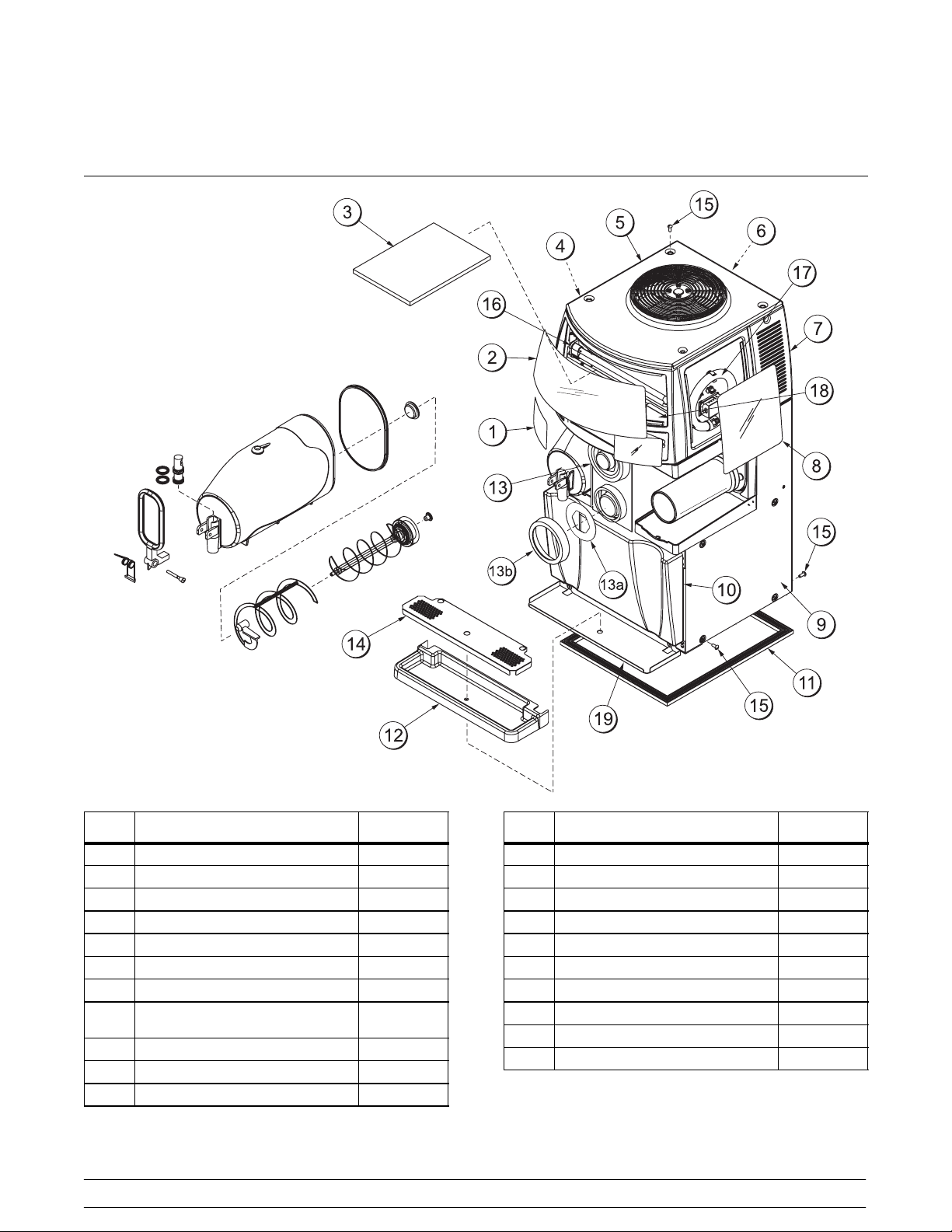
Section 4 Operator Parts Identification
ITEM DESCRIPTION PART NO.
*1 LENS-FLAVOR CARD (L & R) 057161
*2 LENS-DISPLAY-FRONT 057330
3 FILTER-AIR-17.00LX12.00HX.70 052779-8
4 PANEL-SIDE-LOWERLEFT 057052
5 HOOD 057050
6 PANEL-REAR 057054
7 PANEL-SIDE-UPPER 057049
*8 LENS-DISPLAY-LIGHTED-SIDE
(L & R)
9 PANEL-SIDE-LOWERRIGHT 057053
10 DOOR A.-CABINET X57081
11 GASKET-BASE PAN 057154
040802
057160
ITEM DESCRIPTION PART NO.
12 TRAY-DRIP 057051
13 DISPENSER-CUP-ADJUSTABLE 057144
13a KIT-GASKET-4 DISP CUP 057144-4
13b RING-TRIM-DISPENSERCUP 057144-3
14 SHIELD-SPLASH 057044
15 SCREW-10-24X 1/2 TRUSS HD 049189
16 BULB-FLUORESCENT U SHAPE 057157-12
17 BULB-FLUORSCENT CIRCL 054683-2
18 FILTER-AIR 057135
19 SHELF-DRIP TRAY 057307
*CONTACT YOUR PRODUCT SUPPLIER OR LOCAL
TAYLOR DISTRIBUTOR FOR MERCHANDISING
GRAPHICS.
4
Model C903Operator Parts Identification
Page 9
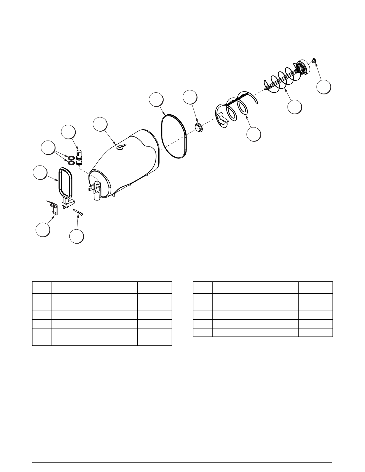
Beater Bowl Assembly
11
3
2
4
5
1
6
7
8
10
9
Figure 1
ITEM DESCRIPTION PART NO.
1 PIN-PIVOT 046461-1
2 SPRING-DRAW 046460
3 HANDLE-DRAW *BLACK 046459-1
4 O-RING *DRAW VALVE 046458
5 VALVE-DRAW 046457
6 BOWL-MIX 10 QT 057036
Model C903 Operator Parts Identification
ITEM DESCRIPTION PART NO.
7 GASKET-BOWL 057042
8 BEARING-FRONT 046462
9 BLADE-SCRAPER-OUTER 056754
10 BEATER-MAGNETIC 052204
11 BEARING-REARWALL-OUTER 052202
5
Page 10
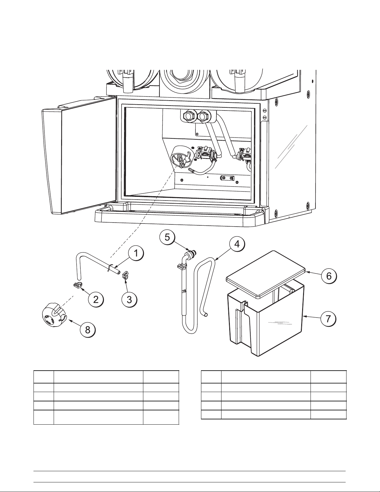
Mix Cabinet Assembly - Standard
ITEM DESCRIPTION PART NO.
1 TUBE-PERISTALTIC PUMP 057125
2 CLAMP-HOSE-SNAP IT 11/32 053630
3 CLAMP-HOSE-SNAP IT 17/32 052021
4 TUBE A. -PRODUCT-TANK
(MIX TANK)
X58433
Figure 2
6
ITEM DESCRIPTION PART NO.
5 O-RING - 3/8 021265
6 COVER-MIX TANK 057924
7 TANK-MIX 057923
8 COVER-PUMP 058832
Model C903Operator Parts Identification
Page 11
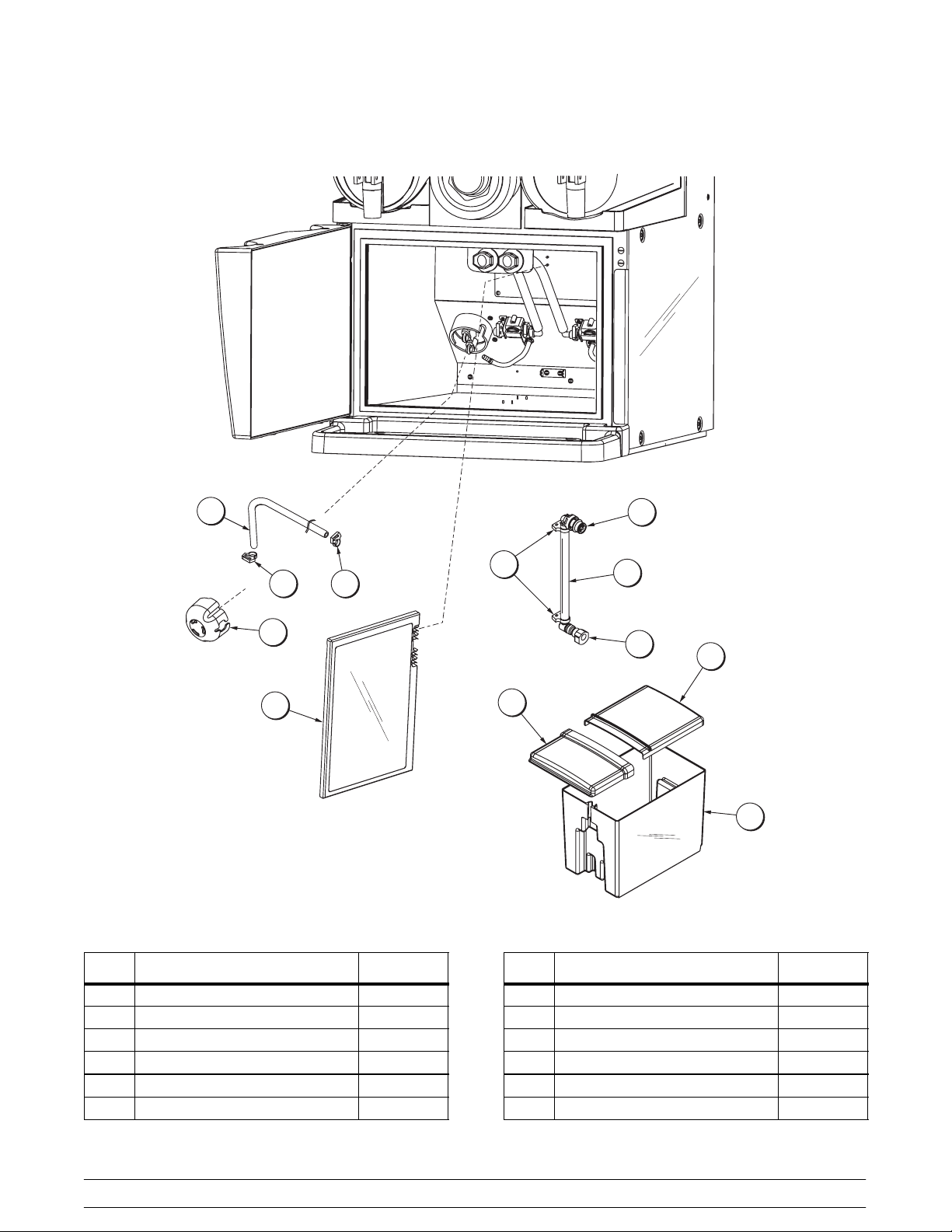
Mix Cabinet Assembly - KanPak
1
4c
2
3
9
8
6
4
4b
4a
5
7
Figure 3
ITEM DESCRIPTION PART NO.
1 TUBE-PERISTALTIC PUMP 057125
2 CLAMP-HOSE-SNAP IT 11/32 053630
3 CLAMP-HOSE-SNAP IT 17/32 052021
4 TUBE A. -PRODUCT (B.I.B.) X58141
4a FITTING-BIB-QD ELBOW 3/8 063103
4b FITTING-BIB-QD MALE 3/8 058143
Model C903 Operator Parts Identification
ITEM DESCRIPTION PART NO.
4c CLAMP-HOSE-SNAP IT 052021
5 COVER-REAR-MIX TANK 062021-R
6 COVER-FRONT-MIX TANK 062021-F
7 TANK-MIX 057923
8 ANTENNA ASSEMBLY 058291
9 COVER-PUMP 058832
060712
7
Page 12
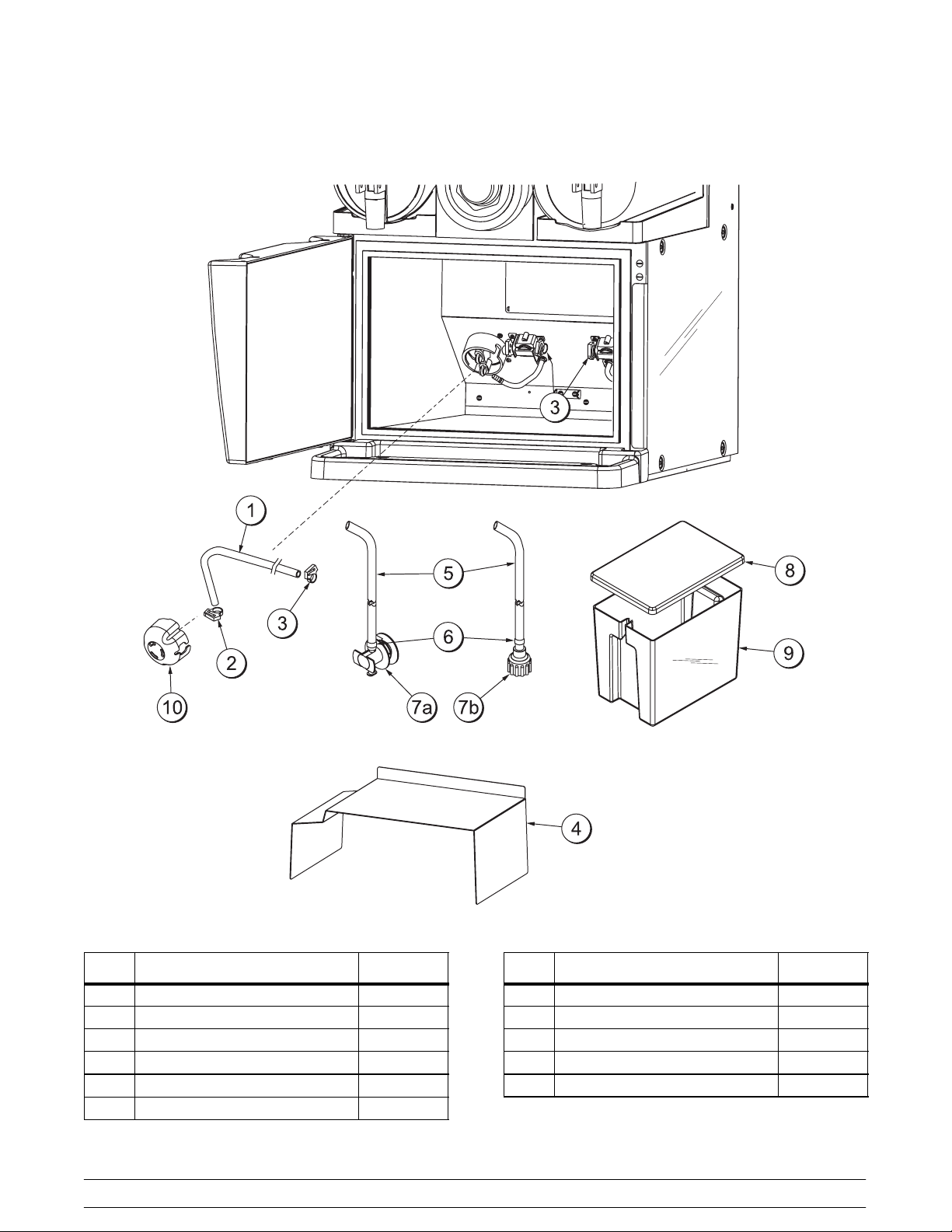
Mix Cabinet Assembly - Optional
ITEM DESCRIPTION PART NO.
1 TUBE-PERISTALTIC PUMP 057125
2 CLAMP-HOSE-SNAP IT 11/32 053630
3 CLAMP-HOSE-SNAP IT 17/32 052021
4 SHELF-CABINET 059188
5 TUBE-VINYL 3/8 ID X 9/16 OD 020943-28
6 CLAMP-HOSE 9/16 STEPLESS 053959
Figure 4
8
ITEM DESCRIPTION PART NO.
7a FITTING-BAG*BIB PEPSI 042945
7b FITTING-BAG *BIB COKE 048176
8 COVER-MIX TANK 057924
9 TANK-MIX 057923
10 COVER-PUMP 058832
Model C903Operator Parts Identification
Page 13
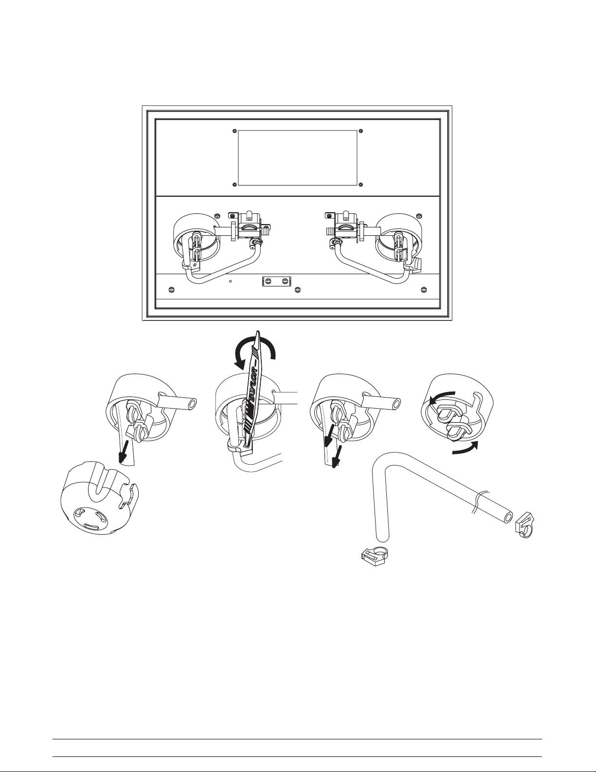
Peristaltic Pump Tube Replacement
Figure 5
Tube Replacement Procedure
1. Remove the black pump cover.
2. Twist open the hose clamps to disengage them
from the hose. (Note: The o-ring tool can be
used as an aid to remove the clamps.)
3. Pull the rounded tabs out all the way to
disengage them from the disk and then rotate
the tabs.
Model C903 Operator Parts Identification
4. Remove the tube.
5. Replace the tube and rotate the tabs back into
the locking position. Make sure the pins are
securely locked in the disk.
9
Page 14
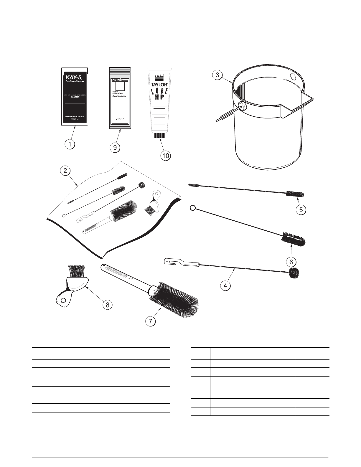
Accessories
ITEM DESCRIPTION PART NO.
1 SANITIZER KAY-5 125 PKTS 041082
2 BRUSH A.-PACKAGE
(CONSISTS OF BRUSH ITEMS
4-8)
3 PAIL-MIX 10 QT. 013163
4 BRUSH-BEATER & SHAFT 500313
5 BRUSH-DOUBLE ENDED 013072
040813
X58793
Figure 6
10
ITEM DESCRIPTION PART NO.
6 BRUSH-DRAW VALVE 1”ODX2” 013073
7 BRUSH-MIX PUMP BODY-3”X7” 023316
8 BRUSH-END-DOOR-SPOUT 039719
9 DETERGENT-YELLOW
DISHSOAP
10 LUBRICANT -TAYLOR HI PERF 048232
*11 TUNE-UP KIT X49463-69
*NOT SHOWN
059070
Model C903Operator Parts Identification
Page 15
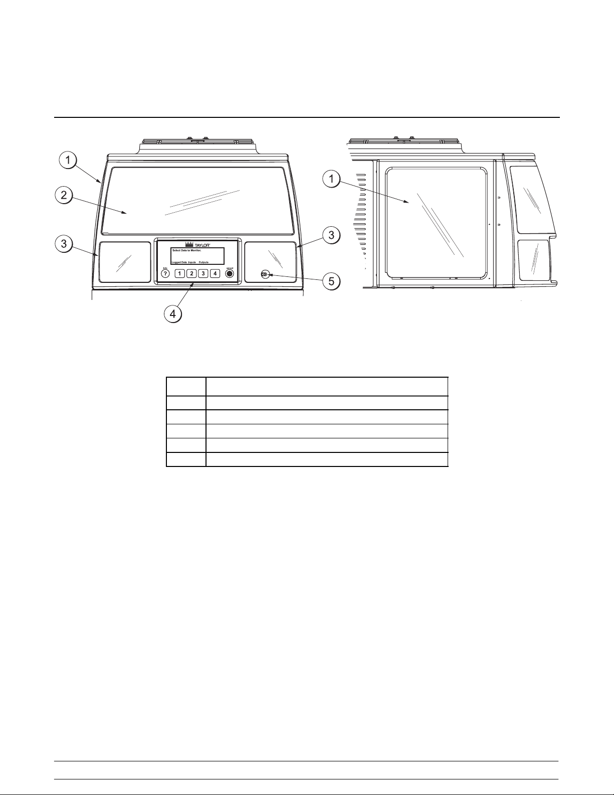
Section 5 Important: To the Operator
Figure 7
ITEM
1 LENS-SIDE
2 LENS-FRONT
3 CARD-FLAVOR
4 CONTROL PANEL
5 POWER SWITCH
Note: Contact your product supplier or local Taylor Distributor for merchandising graphics.
Power Switch
Remove the right side flavor card lens to place the
power switch in the ON position. (See item 5 above.)
When the power switch is placed in the ON position,
the large upper display and the side displays will
illuminate. The flavor card displays will illuminate
when the product is ready to serve. The flavor card
lights will flash if an alarm occurs (syrup out, low
water pressure, etc.).
DESCRIPTION
Viscosity Adjustment
Each bowl has a viscosity adjustment screw. The
left bowl adjustment screw is located on the left side
toward the back of the panel. The right bowl
adjustment screw is located on the right side toward
the back of the panel.
Turn the adjustment screw clockwise to obtain a
thicker product, and counterclockwise to obtain a
thinner product. Make the adjustments in 1/2 turn
increments to achieve proper viscosity.
Model C903 Important: To the Operator
11
Page 16
Display
Passcodes
The C903 display is an eight line by forty character
per line LCD (Liquid Crystal Display) with yellow
backlighting.
Keypad
The C903 keypad has six keys on a touch sensitive
glass panel. These keys are labeled, left to right:
info, 1, 2, 3, 4, and cancel.Theinfo key is used to
display menu related help text. Keys 1, 2, 3, and 4
are soft keys and their function is defined by the key
legends displayed above the keys on line 8 of the
LCD. The cancel key is used to exit or back out of
menus. The sensitivity or response of the keys can
be set in the Set Keypad Sensitivity menu. This
sensitivity can be set to quicken or slow the
response to touching the keys and to allow wipe
down of the display panel without false key
triggering.
If a key is pressed continuously, the key will
auto-repeat. If a key is held down for more than five
seconds, the auto-repeat rate will double.
The system will accept two levels of passcodes:
Operator (default 2133) and Manager (default 3312).
The different levels of passcodes provide different
levels of access to menus and menu items. The
Operator and Manager passcodes can be changed
in the Set Passcode menu.
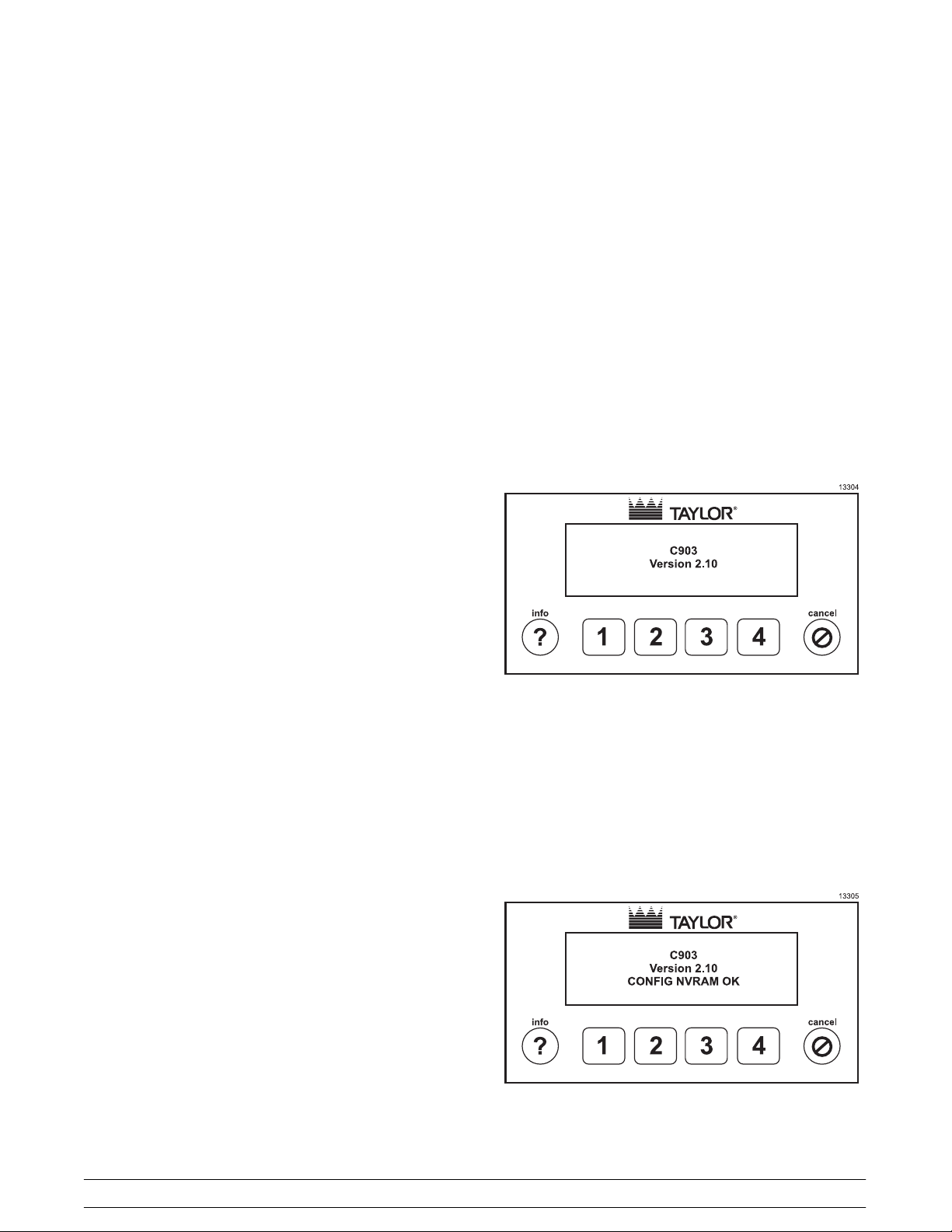
Power Up Initialization Screens
On power up, the model number and firmware
version are displayed on the screen for two seconds
and the audio alarm is turned on for 50ms (chirp).
Flavor Lights
A flavor light is provided for each bowl and is located
above the respective bowl. The flavor light is turned
on when the product in the bowl is ready to serve.
The flavor light is off if the bowl is not in a serving
mode or if the product is not ready to serve. If there
is a fault condition that affects a particular side, the
flavor light for that side is flashed for four seconds
on and four seconds off.
Audio Alarm
An audio alarm provides an audible tone to alert the
operator of alarm conditions and to indicate a
keypress. The audio alarm, when active as an
alarm, is on for ½ second and off for ½ second.
When active as an alarm, the audio alarm can be
silenced for 15 minutes by pressing the cancel key
when the Marketing screen is being displayed.
Figure 8
The memory for configuration data is then tested for
corruption. Configuration memory holds data that is
changed infrequently such as settings entered by
the operator. If the configuration memory is found to
be corrupted, the screen will display the message
“CONFIG NVRAM CORRUPT”. If configuration
memory is not corrupted the message “CONFIG
NVRAM OK” is displayed.
Figure 9
12
Model C903Important: To the Operator
Page 17
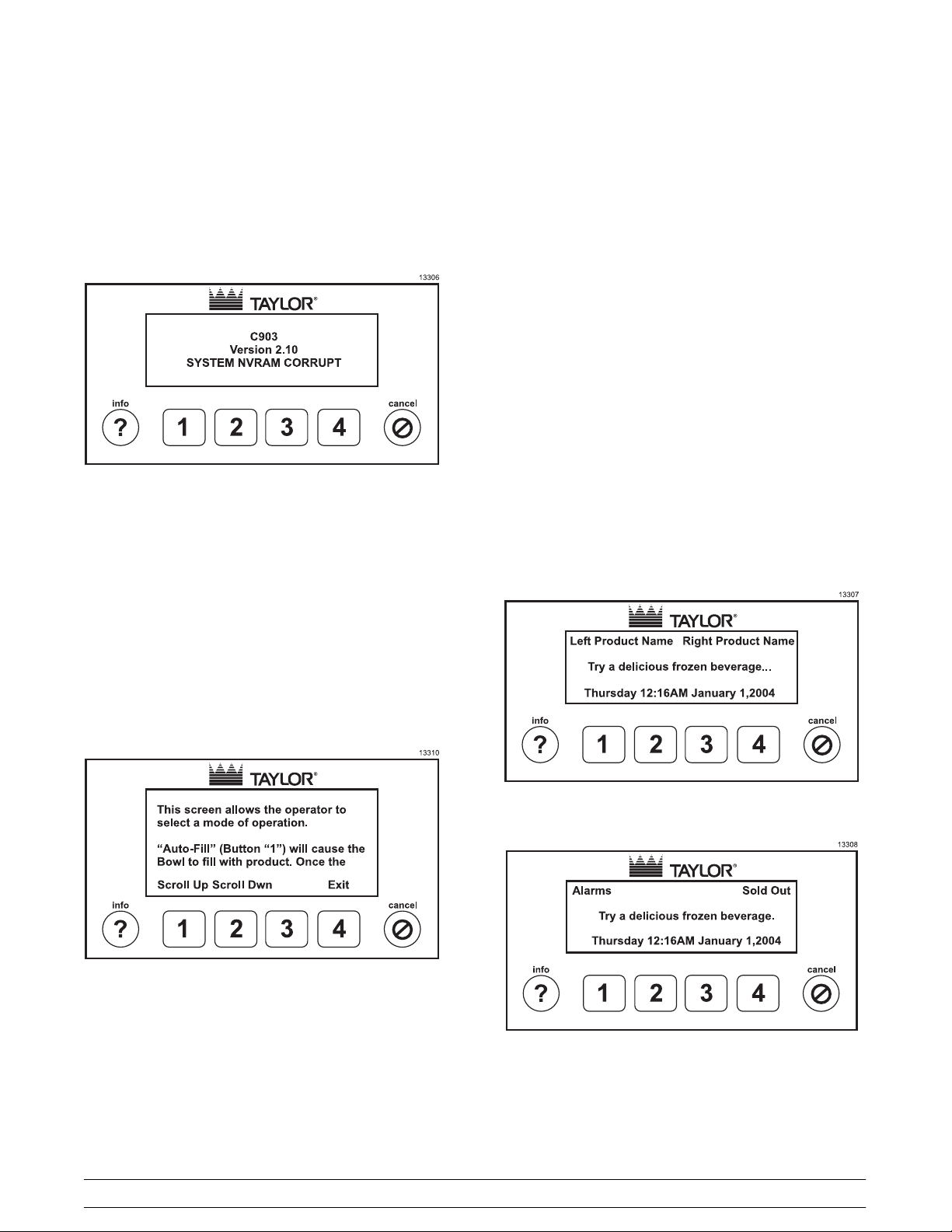
The memory for system data is then tested for
corruption. System memory holds data that is
changed frequently. If the system memory is found
to be corrupted, the screen will display the message
“SYSTEM NVRAM CORRUPT”. If system memory
is not corrupted the message “SYSTEM NVRAM
OK” is displayed.
Marketing Screen
The marketing screen is displayed after the power
up screens. The left product name is displayed on
line 1 in the first 20 columns and the right product
name is displayed in last 20 columns. On line 4, a
marketing message is displayed. On line 8, the day
of the week, the time of day, and the date are
displayed.
If the unit is a non-RFID unit, the product names will
be blank unless product names have been entered
by an operator.
If the unit is an RFID unit, the product names are
read from the RFID tag on the product boxes. If no
box is present, the product name is replaced by the
message “NO BOX”.
Figure 10
Operator Menus
Help
Help text is available in all operator and manager
accessible menus except the marketing and
passcode screens. The help text is brought up by
pressing the info key.
If there is an alarm condition, the product names are
replaced by the message, “Alarms”. If a syrup out or
sold out condition occurs, the display will show the
message “Syrup Out” or “Sold Out”, respectively,
alternating with the message “Alarms”.
Figure 12
Figure 11
Pressing key 1 (Scroll Up) will scroll the text down
to display the preceding text (up). Pressing key 2
(Scroll Dwn) will scroll text up to display the
following text (down). Pressing key 4 (Exit)orthe
cancel key will exit the help menu and return to the
menu from which the help was called.
Model C903 Important: To the Operator
If the audio alarm is on, pressing the cancel key will
silence the audio alarm for 15 minutes.
13
Figure 13
Page 18
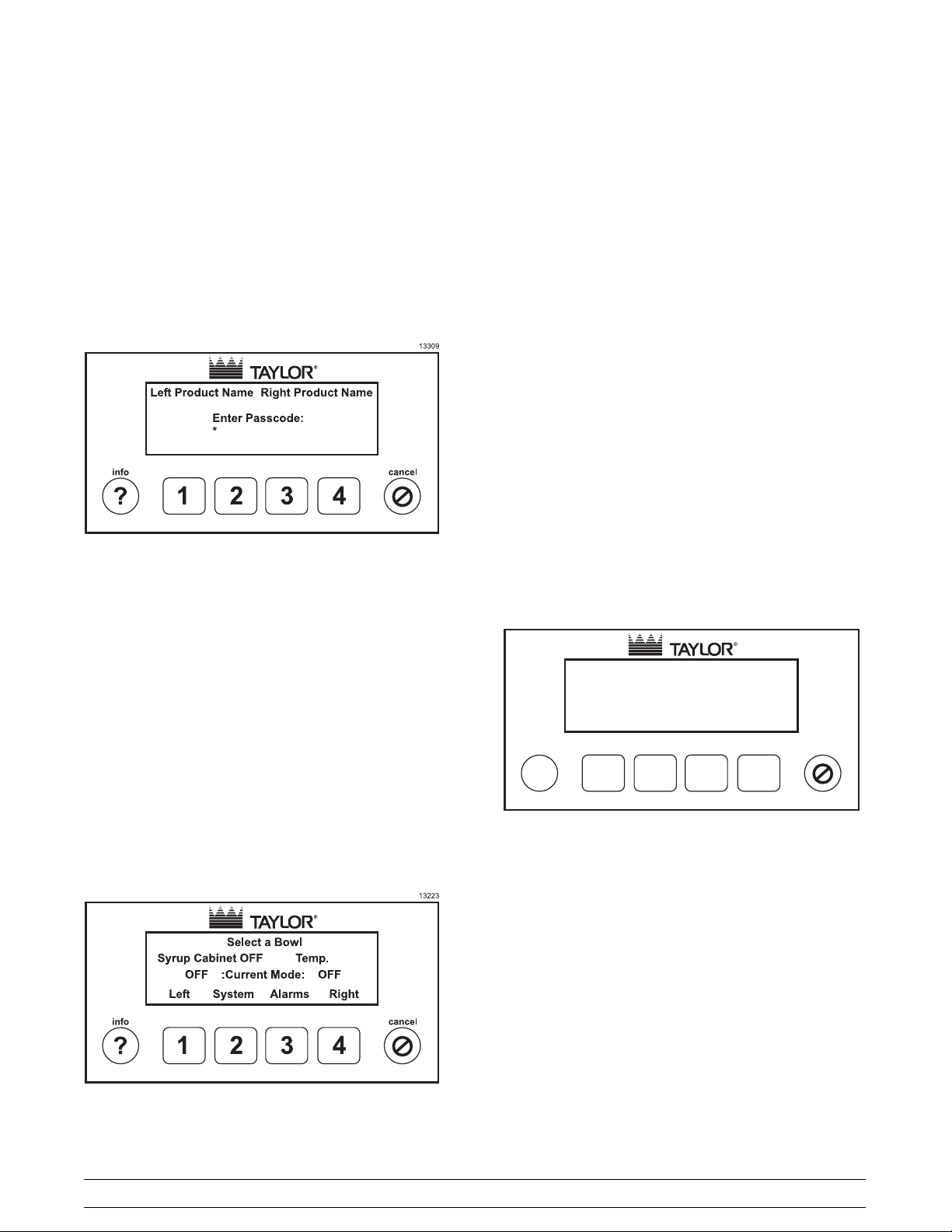
The menus are accessed by entering a four digit
passcode. Valid passcode keys are keys 1, 2, 3, and
4. If a key, other than the cancel key, is pressed
when the Marketing Screen is being displayed, the
passcode screen is displayed.
Passcode Menu
Figure 14
In the Bowl Select Menu, the product names are
displayed on line 1. The syrup cabinet temperature
is displayed on line 4. On line 6, the current mode of
the left and right bowls is displayed. On line 8, the
keypad legends are displayed for keys 1-4. Pressing
key 1 will change to the left Select Mode Menu,
pressing key 2 will change to the System Menu, and
pressing the 4 key will change to the right Select
Mode Menu. If there is an alarm active, the legend
above key 3 will be Alarm otherwise it will be blank.
When the alarm legend is present, pressing key 3
will change to the Alarm Menu. Pressing the cancel
key will return to the Marketing Screen.
If the bowl is already in Rinse or Sanitize mode,
pressing key 1 (Left) or pressing key 2 (Right) will
jump directly to the Rinsing or Sanitizing Menu
instead of going to the Bowl Mode Menu.
Bowl Mode Menu
An asterisk is displayed for each keypress, including
the first keypress from the Marketing Screen. Valid
passcode keys are the 1, 2, 3, and 4 keys. If no key
is entered for 30 seconds and the passcode entered
is not valid, the screen will return to the marketing
screen. Pressing the cancel key will return to the
Marketing Screen.
If a valid passcode is entered, the Bowl Select Menu
will be displayed.
Bowl Select Menu
Figure 15
13121
Select a Mode for the Left Bowl.
Current Mode: OFF
1
No-Fill
Chill
More
234
cancel
Auto-Fill
info
?
Figure 16
On line 1, the left and right product names are
displayed. On RFID units, this product name is read
from the product box. On non-RFID units, the
product name must be entered using the Product
Name menu. On line 4, the current bowl mode is
displayed. On line 8, are the key legends for
selecting the mode. Pressing key 1 (Auto-Fill) will
place the bowl into Auto-Fill mode. Pressing key 2
(No Fill) will place the bowl into No Fill mode.
Pressing key 3 (Chill) will place the bowl into Chill
mode. Pressing key 4 (More) will change to the
Rinse/Sanitize menu. Pressing the cancel key will
return to the Bowl Select Menu.
14
Model C903Important: To the Operator
Page 19
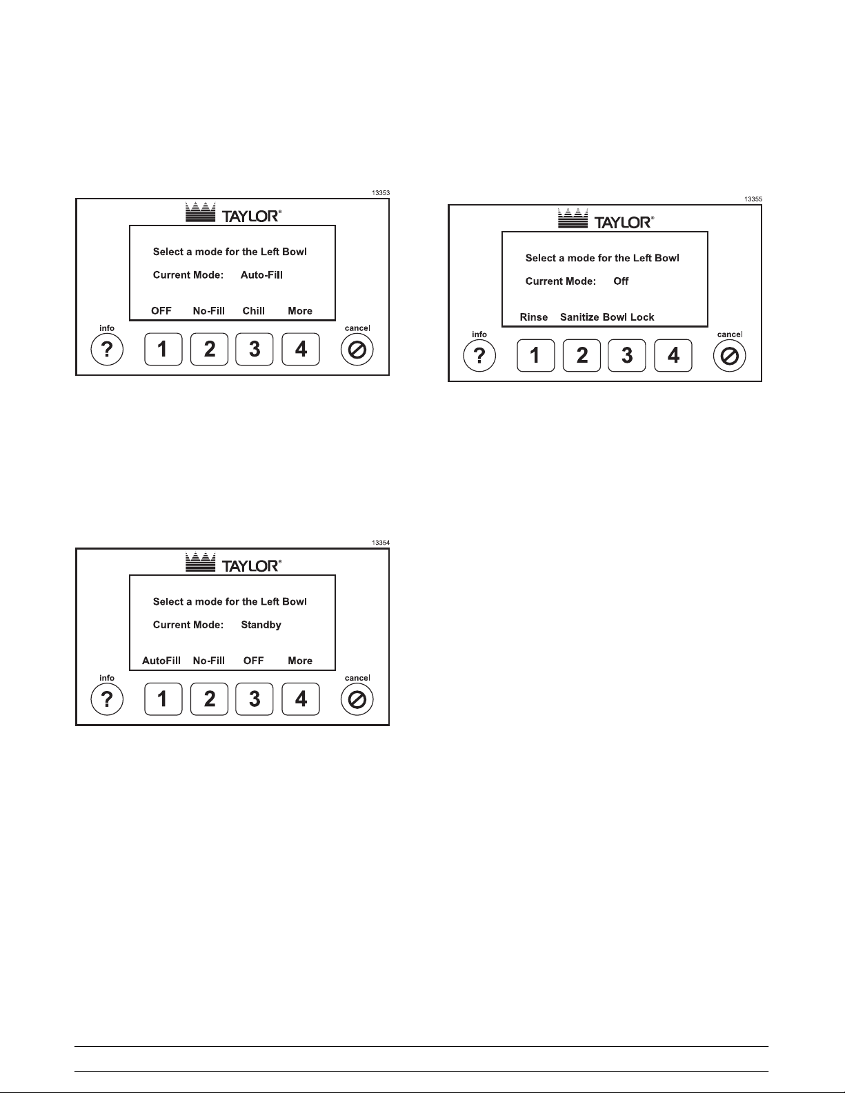
When the bowl is in Auto-Fill, No-Fill, or Chill mode,
the respective key legend will show OFF. Pressing a
key, when the key legend says OFF, will place the
bowl into Off mode.
Rinse/Sanitize Menu
Press the MORE (4) key when in the Bowl Mode
Screen to go to the Rinse/Sanitize Menu.
Figure 17
If a bowl is in Standby mode, the Chill key legend
will show OFF. In this case, to place the bowl into
Chill mode, the bowl would first have to be placed
into Off mode and then can be placed into Chill
mode. Only the system can place a bowl into
Standby mode. The system will place a bowl into
Standby mode during Defrost or because of a fault.
Figure 18
This menu is the same for the right bowl,
respectively.
Figure 19
From the Rinse/Sanitize Menu, the operator can
place the bowl into Rinse Mode, Sanitize Mode, or
energize the bowl lock to remove the bowl. A bowl
can only be placed into Rinse or Sanitized mode if
the bowl mode is Off, Rinsed, or Sanitizedand all of
the level sensors are exposed.
Pressing key 1 will place the bowl into Rinse Mode
and change to the Rinsing Menu.
Pressing key 2 will place the bowl into Sanitize
mode and change to the Sanitizing Menu.
Pressing key 3 will raise the bowl lock pin. Pressing
key 3 while the bowl lock pin is raised will release
the bowl lock pin. When key 3 is pressed and the
bowl lock pin is raised, the bowl lock pin will
automatically de-energize after 15 seconds if key 3
is not pressed to de-energize the bowl lock pin. The
bowl lock key will only respond if the liquid level in
the bowl is below the Mix Low sensor.
Pressing the cancel key will return to the Bowl
Mode Menu. This menu is the same for the right
bowl, respectively.
Model C903 Important: To the Operator
15
Page 20
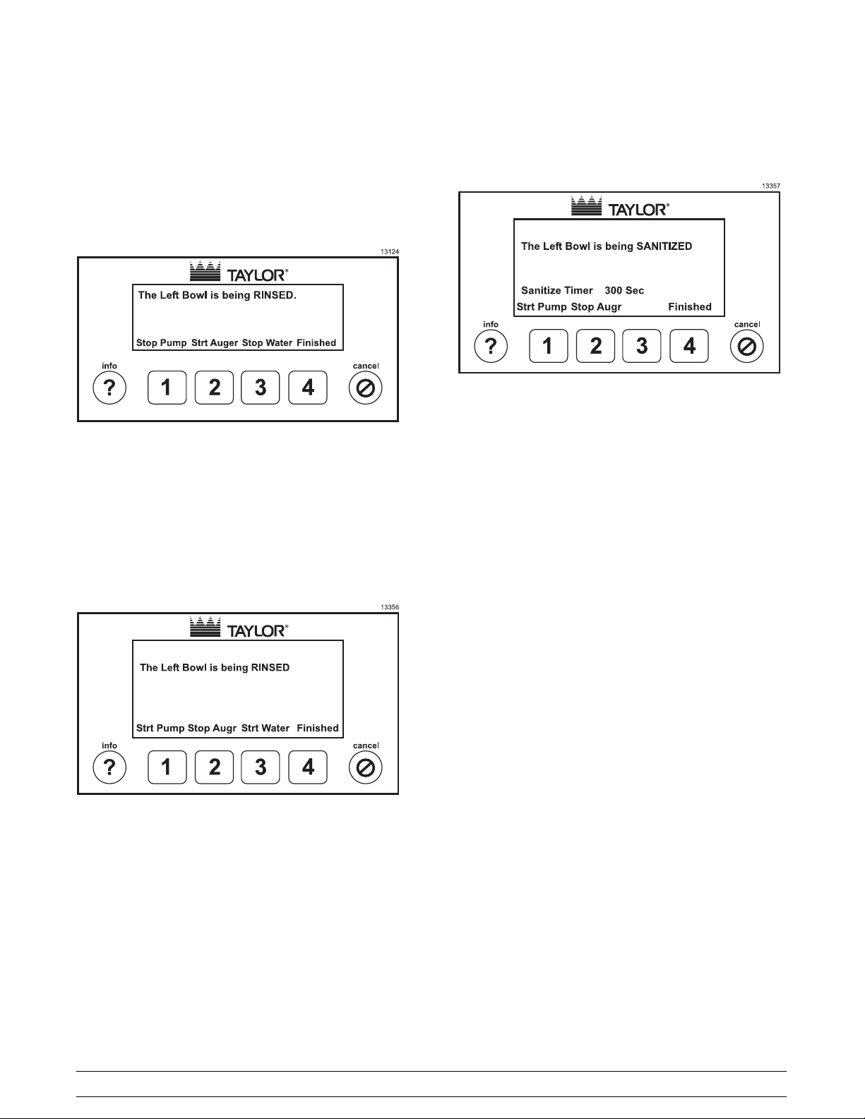
Rinsing Menu
Upon entering this menu, the bowl will have been
placed into the Rinse mode, with the syrup pump on,
the auger off, and the water on, unless there is a
fault that prevents the syrup pump or water from
being turned on.
Sanitizing Menu
Figure 22
Figure 20
The auger will turn on when the level in the bowl
reaches the mix full probe. Pressing key 1 will start
and stop the syrup pump. Pressing key 2 will start
and stop the auger. Pressing key 3 will start and
stop the water. Pressing key 4 will end the Rinse
mode and return to the Bowl Mode Menu. Pressing
the cancel key will return to the Bowl Select Menu
while leaving the bowl in the Rinse mode.
Figure 21
This menu is the same for the right bowl,
respectively.
Upon entering this menu from the Rinse/Sanitize
Menu, the bowl will have been placed into the
Sanitize mode with the syrup pump on and the
auger off, unless there is a fault that prevents the
syrup pump from being turned on.
The auger will turn on when the level in the bowl
reaches the mix full probe. Pressing key 1 will start
and stop the syrup pump. Pressing key 2 will start
and stop the auger. Pressing key 4 will end the
Sanitize mode and return to the Bowl Mode Menu.
Pressing the cancel key will return to the Bowl
Select Menu while leaving the bowl in the Sanitize
mode.
A Sanitize Timer will count down from 300 seconds
to zero. The timer will count down only if the auger is
running and the bowl is filled to the Mix Over probe.
If a lockout cleaning has been performed, the bowl
mode will show “Bowl Cleaned”, otherwise the bowl
mode will show “Sanitized”. The system will
automatically finish the Sanitizing mode when the
300 seconds (5 minutes) has counted down to 0.
This menu is the same for the right bowl,
respectively.
16
Model C903Important: To the Operator
Page 21
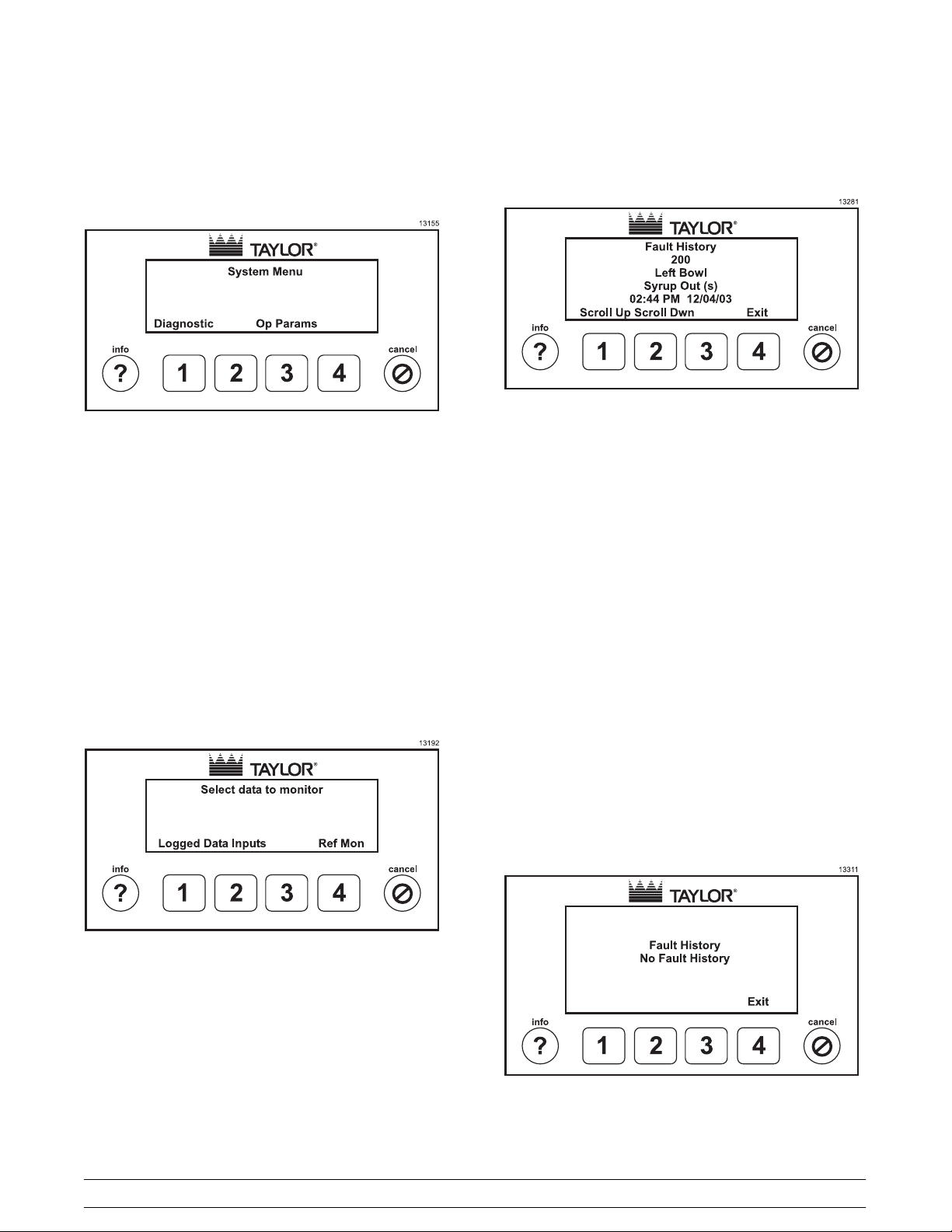
System Menu
Logged Data Menu
Figure 25
Figure 23
Pressing key 1 (Diagnostic) will change to the
Diagnostic Menu. Pressing key 3 (Op Params) will
change to the Operator Parameters Menu. Pressing
the cancel key will return to the Bowl Select Menu.
Diagnostic Menu
In the Logged Data Menu, the operator can view the
history of faults that the system has logged. Line 2 is
the menu title. Line 3 displays the record number
with the highest number being the most recent fault.
Line 4 displays the side on which the fault occurred.
The sides can be Left, Right, or System. System
indicates that the fault occurred on a device that is
common to both sides such as Low Water Pressure
fault. Line 5 displays the timestamp for the fault.
Pressing key 1 (Scroll Up) will increment the record
number, i.e. display the more recent fault. If the
current fault is the last, then key 1 will display the
first fault. Pressing key 2 (Scroll Dwn) will
decrement the record number, i.e. display the
previous fault. If the current fault is the oldest fault,
then key 2 will display the last fault. Pressing key 4
(Exit)orthecancel key will exit the menu and
return to the Diagnostics Menu.
If there are no faults, the following screen will be
displayed.
Figure 24
Pressing key 1 (Logged Data) will change to the
Diagnostic Menu. Pressing key 2 (Inputs) will
change to the Inputs Menu. Pressing key 4 (Refr
Mon) will change to the Refrigeration Monitor menu.
Pressing the cancel key will return to the Bowl
Select Menu.
Model C903 Important: To the Operator
17
Figure 26
Page 22

Inputs Menu (Diagnostic Menu)
Figure 27
Pressing key 1 (Scroll Up) will scroll up through the
list of inputs. Pressing key 2 (Scroll Dwn) will scroll
down through the list of inputs. Pressing key 4 (Exit)
or the cancel key will exit the menu and return to
the Diagnostics Menu.
Refrigeration Monitor Menu
This menu displays the current values for inputs.
The description of the input is in the first column
(left) of the display. The second column of
information is the input value. The third column
displays internal values which may be useful for
diagnosis of problems when contacting tech support.
The inputs and their values are:
Left Bowl Temperature °F
Right Bowl Temperature °F
Cabinet Temp °F
Left Mix Low Yes/No
Left Mix Full Yes/No
Left Mix Over Yes/No
Right Mix Low Yes/No
Right Mix Full Yes/No
Right Mix Over Yes/No
Left Syrup Out Sense Yes/No
Right Syrup Out Sense Yes/No
Left SyrupOut Switch OK/OUT
Right Syrup Out Switch OK/OUT
HPCO Yes/No
Water Pressure Switch OK/Low
Left Viscosity Switch OK/Low
Right Viscosity Switch OK/Low
Filter Switch Yes/No
Left Bowl In Place Switch Yes/No
Right Bowl In Place Switch Yes/No
Figure 28
This menu allows the operator to view various
parameters related to refrigeration of the product.
Line 1 displays the mode of the left and right bowls.
Line 2 displays the viscosity status. Line 3 displays
the setpoint, i.e. the temperature above which
refrigeration is turned off. Line 4 displays the current
bowl temperatures. Line 5 displays the current state
of the liquid line solenoids. Line 6 displays the syrup
cabinet temperature and the compressor state.
Pressing key 4 (Exit)orthecancel key will exit this
menu and return to the Diagnostics Menu.
Operator Parameters Menu
The following screen is displayed if the Operator
passcode is entered.
Figure 29
18
Model C903Important: To the Operator
Page 23

The following screen is displayed if the Manager
passcode is entered.
Figure 30
Version Menu
In this menu, the firmware and language versions
are displayed. Pressing key 4 (Exit)orthecancel
key will return to the System Menu.
This menu displays a list of operating parameters.
Pressing key 1 (Scroll Up) will move the cursor, >,
up through the list. Pressing key 2 (Scroll Dwn) will
move the cursor, >, down through the list. Pressing
key 4 (Enter) will select the list item pointed to by
the cursor. Pressing the cancel key will exit back to
the System Menu.
Only the first two items are available under the
Operator passcode. All of the following parameters
are available under the Manager passcode.
Version
View/Clear Component Run Data
Set Water to Syrup Ratio
Set Auto Defrost and Auto Start Times
Set Clock
Set Initial Freezedown Temperature
Download Data to Card(s)
Change Keypad Sensitivity
Set Lockout Interval
Set Lockout Notice Time
Set Lockout NoFill Time
Figure 31
View/Clear Component Run Data
Figure 32
This menu displays a list of run time parameters.
Pressing key 1 (Scroll Up) will move the cursor, >,
up through the list. Pressing key 2 (Scroll Dwn) will
move the cursor, >, down through the list. Pressing
key 4 (Enter) will select the list item pointed to by
the cursor. Pressing the cancel key will exit back to
the System Menu.
Model C903 Important: To the Operator
19
Page 24

The complete list of operator parameters is listed
below:
Syrup Pump Tube Run Volume Menu
Figure 33
This menu allows the operator to view and clear the
counter for the syrup pump tube run volume.
Pressing key 1 (LEFT) will select the left counter.
Pressing key 2 (RIGHT) will select the right counter.
Pressing the cancel key will return to the View/Clear
Component Run Data Menu.
Figure 35
Set Water to Syrup Ratio Menu
In this menu, the operator can set the water to syrup
ratio to achieve a desired brix (percent sugar).
Figure 34
The side selected is displayed on line 2. The value
of the counter is displayed on line 6. The volume
displayed is in units of 0.01 oz. In this display, the
volume would be 20.23 oz. Pressing key 1 (Clear)
will set the counter to zero. Pressing key 4 (Exit)or
the cancel key will return to the View/Clear
Component Run Data Menu without any change to
the value displayed for the counter.
Figure 36
Pressing key 1 (LEFT) will select the left side.
Pressing key 2 (RIGHT) will select the right side.
Pressing the cancel key will return to the Operator
Parameters Menu.
Figure 37
20
Model C903Important: To the Operator
Page 25

Pressing key 2 (+++) will increase the water ratio in
0.1 increments. Pressing key 3 (---) will decrease
the water ratio in 0.1 increments. Pressing key 4
(Enter) will save the setting and return to the Set
Water to Syrup Ratio bowl select menu. Pressing
the cancel key will return to the Set Water to Syrup
Ratio bowl select menu without saving any changes.
Set Auto Defrost and Auto Start Times Menu
In this menu, the operator can set the time at which
the system will automatically enter the defrost mode
and set the time at which the system will
automatically exit defrost mode and return to a
freezing mode.
Note: During the defrost mode, refrigeration is shut
off and the product is allowed to liquify. The product
is then maintained at approximately 38°F (3.3°C).
Typically allow 4 - 6 hours for this to take place.
Auto Defrost Time Menu
In this menu, the operator can set the time at which
the system will automatically enter defrost mode.
Figure 39
Pressing key 1 (-->) will move the cursor between
hours and minutes. Pressing key 2 (+++) will
increment and pressing key 3 (---) will decrement the
value, hours or minutes, above the cursor. Pressing
key 4(Enter)will save the value and return to the
Set Auto Defrost and Auto Start Times Menu.
Pressing the cancel key will return to the Set Auto
Defrost and Auto Start Times Menu without saving
any changes.
Figure 38
Pressing key 1 (Defrost) will enter the menu for
setting the Defrost time. Pressing key 2 (Freeze) will
enter the menu for setting the Auto Freeze time.
Pressing key 3 (Disabled/Enabled) will toggle
between Enabled and Disabled and save the value,
enabled or disabled. Pressing the cancel key will
return to the Operator Parameters Menu.
Auto Freeze Time Menu
In this menu, the operator can set the time at which
the system will automatically exit defrost mode and
enter the freezing mode that was present before
entering Defrost mode.
Figure 40
Model C903 Important: To the Operator
21
Page 26

Pressing key 1 (-->) will move the cursor between
hours and minutes. Pressing key 2 (+++) will
increment and pressing key 3 (---) will decrement the
value, hours or minutes, above the cursor. Pressing
key 4(Enter)will save the value and return to the
Set Auto Defrost and Auto Start Times Menu.
Pressing the cancel key will return to the Set Auto
Defrost and Auto Start Times Menu without saving
any changes.
Set Clock Menu
In this menu, the operator can set the current time
and date. If the Lockout Interval has been set to a
non-zero value, the time and date can only be
changed when both bowls are in a Bowl Cleaned
state.
Set Initial Freezedown Temperature
In this menu, the operator can set the initial
temperature at which freezing control will begin.
Note: This value is not used at this time.
Figure 42
Pressing key 1 (LEFT) will select the left side.
Pressing key 2 (RIGHT) will select the right side.
Pressing the cancel key will return to the Operator
Parameters Menu.
Figure 41
Pressing key 1 (-->) will move the cursor to the right.
If the cursor is on the century, the cursor will wrap to
hours. Pressing key 2 (+++) will increment and
pressing key 3 (---) will decrement the value above
the cursor. Pressing key 4(Enter)will save the
value and return to the Operator Parameters Menu.
Pressing the cancel key will return to the Operator
Parameters Menu without saving any changes.
If an invalid date is entered, such as February 30,
“INVALID DATE” will be displayed on line 6.
Pressing key 4(Exit)or the cancel key will return to
the Set Clock edit screen.
Figure 43
Pressing key 2 (+++) will increase the temperature
in 0.1°F increments. Pressing key 3 (---) will
decrease the temperature in 0.1°F increments.
Pressing key 4 (Enter) will save the setting and
return to the Operator Parameters Menu. Pressing
the cancel key will return to the Operator
Parameters Menu without saving any changes.
22
Model C903Important: To the Operator
Page 27

Download Data to Card(s) (RFID Units Only)
In this menu, the operator can download logged data
to a customer card. This procedure can only be
performed if the unit is equipped for RFID.
If a valid card cannot be found, the following screen
is displayed.
Figure 47
Figure 44
To download the logged data, a customer card
should be held up against the white panel above the
left bowl.
Figure 45
Pressing key 1 (Continue) will begin the download
process. The following screen will be displayed while
the system attempts to write to the customer card.
Pressing key 4(Exit)or the cancel key will return to
the previous screen.
If a valid card is found, the following screen is
displayed when the download is complete.
Figure 48
Pressing key 4(Exit)or the cancel key will return to
the Operator Parameters Menu.
Figure 46
040526
Model C903 Important: To the Operator
23
Page 28

Change Keypad Sensitivity
In this menu, the operator can change the sensitivity
or response of the keypad. Higher values increase
the sensitivity and lower values decrease the
sensitivity. Lower keypad sensitivity will help prevent
unintentional detection of key presses.
Pressing key 1 (LEFT) will select the left side.
Pressing key 2 (RIGHT) will select the right side.
Pressing the cancel key will return to the Operator
Parameters Menu.
Figure 51
Figure 49
Pressing key 2 (+++) will increase the sensitivity in
increments of 10. Pressing key 3 (---) will decrease
the sensitivity in increments of 10. Pressing key 4
(Enter) will save the setting and return to the
Operator Parameters Menu. Pressing the cancel
key will return to the Operator Parameters Menu
without saving any changes.
Set Cleaning Lockout Interval
In this menu, the operator can set the Lockout
Interval, in days. The Lockout Interval is the number
of days at which the system will no allow the unit to
be placed in a freezing mode until the unit is
cleaned.
Pressing key 2 (+++) will increase the Lockout
Interval. Pressing key 3 (---) will decrease the
Lockout Interval. Pressing key 4 (Enter) will save
the setting and return to the Operator Parameters
Menu. Pressing the cancel key will return to the
Operator Parameters Menu without saving any
changes.
Set Cleaning Lockout Notice Time
In this menu, the operator can set the Lockout
Notice Time. The Lockout Notice Time is the
number of hours prior to a cleaning lockout that the
system will generate an alarm to forewarn the
operator.
Figure 50
24
Figure 52
Model C903Important: To the Operator
Page 29

Pressing key 1 (LEFT) will select the left side.
Pressing key 2 (RIGHT) will select the right side.
Pressing the cancel key will return to the Operator
Parameters Menu.
Pressing key 1 (LEFT) will select the left side.
Pressing key 2 (RIGHT) will select the right side.
Pressing the cancel key will return to the Operator
Parameters Menu.
Figure 53
Pressing key 2 (+++) will increase the Lockout
Notice Time. Pressing key 3 (---) will decrease the
Lockout Notice Time. Pressing key 4 (Enter) will
save the setting and return to the Operator
Parameters Menu. Pressing the cancel key will
return to the Operator Parameters Menu without
saving any changes.
Set Cleaning Lockout NoFill Time
In this menu, the operator can set the Lockout NoFill
Time. The Lockout NoFill Time is the number of
hours prior to a cleaning lockout that the system will
automatically switch to AutoNoFill mode. This is to
minimize product loss when cleaning.
Figure 55
Pressing key 2 (+++) will increase the Lockout NoFill
Time. Pressing key 3 (---) will decrease the Lockout
NoFill Time. Pressing key 4 (Enter) will save the
setting and return to the Operator Parameters Menu.
Pressing the cancel key will return to the Operator
Parameters Menu without saving any changes.
Set Cleaning Lockout Mix Low Time
In this menu, the operator can set the Lockout Mix
Low Time. The Lockout Mix Low Time is the number
of hours prior to a cleaning lockout that the system
will not generate an alarm if the bowl goes below
mix low. This is to minimize product loss when
cleaning.
Figure 54
Model C903 Important: To the Operator
25
Figure 56
Page 30

Pressing key 1 (LEFT) will select the left side.
Pressing key 2 (RIGHT) will select the right side.
Pressing the cancel key will return to the Operator
Parameters Menu.
Figure 57
Pressing key 2 (+++) will increase the Lockout Mix
Low Time. Pressing key 3 (---) will decrease the
Lockout Mix Low Time. Pressing key 4 (Enter) will
save the setting and return to the Operator
Parameters Menu. Pressing the cancel key will
return to the Operator Parameters Menu without
saving any changes.
Figure 59
Pressing key 1 (-->) will move the cursor to the right.
If the cursor is on the fourth digit, the cursor will
wrap to the first digit. Pressing key 2 (+++) will
increment and pressing key 3 (---) will decrement the
digit above the cursor. Pressing key 4(Enter)will
save the value and return to the Operator
Parameters Menu. Pressing the cancel key will
return to the Operator Parameters Menu without
saving any changes. This menu screen is used for
both the operator and manager passcodes.
Change Passcode
In this menu, the operator can change the operator
and manager passcodes.
Figure 58
Pressing key 1 (Operator) will select the menu for
changing the operator passcode. Pressing key 2
(Manager) will select the menu for changing the
manager passcode. Pressing key 4(Exit)or the
cancel key will return to the Operator Parameters
Menu.
Product Name Menu
In this menu, the operator can set the product
names for the left and right sides. If the system is an
RFID unit, the product names are automatically read
from the product tags.
Figure 60
26
Model C903Important: To the Operator
Page 31

Pressing key 1 (LEFT) will select the left side.
Pressing key 2 (RIGHT) will select the right side.
Pressing the cancel key will return to the Operator
Parameters Menu.
Figure 61
Alarm Menu
The Alarm menu is entered by pressing key 3
(Alarm) in the Bowl Select menu. Key 3 (Alarm) will
only appear in the Bowl Select menu if there is an
active alarm.
Pressing key 1 (-->) will move the cursor to the right.
If the cursor is on the last character, the cursor will
wrap to the first character. Pressing key 2 (+++) will
increment and pressing key 3 (---) will decrement the
character above the cursor. Pressing key 4(Enter)
will save the value and return to the Operator
Parameters Menu. Pressing the cancel key will
return to the Operator Parameters Menu without
saving any changes.
Figure 62
Figure 63
Pressing key 1 (Select) will select the displayed fault
and allowing clearing of only that fault. Pressing key
2 (Clear All) will clear all active faults. Pressing key
3(ScrollUp)will scroll up through the active faults.
Pressing key 4 (Scroll Dwn) will scroll down through
the active faults. Pressing the cancel key will return
to the Bowl Select menu.
Figure 64
Pressing key 2 (+++) will increase the water ratio in
0.1 increments. Pressing key 3 (---) will decrease
the water ratio in 0.1 increments. Pressing key 4
(Enter) will save the setting and return to the Set
Water to Syrup Ratio bowl select menu. Pressing
the cancel key will return to the Set Water to Syrup
Ratio menu.
Model C903 Important: To the Operator
Pressing key 1 (Select) will select the displayed fault
and allowing clearing of only that fault. Pressing key
2 (Clear All) will clear all active faults. Pressing key
3(ScrollUp)will scroll up through the active faults.
Pressing key 4 (Scroll Dwn) will scroll down through
the active faults. Pressing the cancel key will return
to the Bowl Select menu.
27
Page 32

The possible alarms are described below:
HPCO
The HPCO fault indicates that a High Pressure Cut
Out occurred on the compressor.
Syrup Out (S)
A syrup out was detected from the vacuum switch.
This will occur when a bag-in-box of syrup runs out
of syrup or if nothing is connected to the quick
disconnect.
Syrup Out (C)
A syrup out was detected from the conductivity
sensor in the syrup pump tubing. The system
detects whether there is fluid in the syrup pump
tubing by measuring the conductivity of the fluid in
the tubing. If there is air in the tubing, as would be
the case if a mix tank or pail of fluid ran out of fluid,
then the conductivity measured would be low.
Low Water Pressure
Thermistor Fault
A thermistor fault is generated if the control
determines that a thermistor is shorted, open, or
outside of the valid measurement range. If there is a
thermistor fault, temperature displays for that
thermistor will display SHRT, OPEN,orOVER
instead of a temperature. If the bowl mode is
AutoFill, AutoNoFill, Chill mode, or Standby mode,
the bowl mode is changed to Off mode.
Pump On Too Long
The Pump On Too Long fault is generated if the
syrup pump runs for more than a period of time
dependent upon the water to syrup ratio.
Cleaning Lockout
The Cleaning Lockout fault is generated to inform
the operator that the system requires cleaning.
Bowl Overfill
The Bowl Overfill fault is generated if the system
detects that the level of product in a bowl has
reached the Mix Over sensor in AutoFill, AutoNoFill,
Chill, and Standby modes. This may be due to too
high of a viscosity setting or too high of a water to
syrup ratio.
Mix Low
The system monitors a sensor to determine if the
water pressure is too low. When the system detects
that the water pressure is low, there is a delay of 60
seconds before the Low Water Pressure alarm is
generated. If after 60 seconds, the water pressure is
still low, a Low Water Pressure alarm is generated.
If the bowl is in Rinsing mode, the mode is changed
to Off mode. If the bowl mode is AutoFill, the bowl
mode will be changed by the control to AutoNoFill
mode and if the water pressure returns and the
alarm is still active, the alarm will be automatically
cleared and the bowl mode will automatically be
changed back to AutoFill mode.
Lockout Notice
The Lockout Notice alarm is generated when the
time before a cleaning lockout is less than or equal
to the Lockout Notice Time. The Lockout Notice
alarm is generated to remind the operator that a
cleaning lockout is will be occurring soon. The
Lockout Notice alarm is regenerated every 60
minutes until the cleaning lockout occurs.
A Mix Low fault is generated if the product in the
bowl drops below the Mix Low sensor in AutoFill,
AutoNoFill, Chill, or Standby mode. (At this time,
Beta version x243, this alarm is not active since
product level is now allowed to go below Mix Low in
the serving modes.)
Locked Auger
A Locked Auger fault is generated if the system
detects that an auger is not turning. When a locked
auger is detected, the bowl is placed into Off mode.
If the temperature of the product is greater than
30.0°F at the time of the Locked Auger fault, the
system will then, after a delay of two minutes,
automatically place the bowl back into the mode the
bowl was in at the time of the Locked Auger fault.
Expired Product
An Expired Product fault is generated if the system
detects that the current date is greater than the
expiration date read from the box . This fault will
only occur on systems with RFID. This fault is only
informative and syrup will continue to be pumped
from the box.
28
Model C903Important: To the Operator
Page 33

Product Lifespan Expired
AutoFill and AutoNoFill Mode
A Product Lifespan Expired fault is generated if the
system detects that 30 days has passed since a box
of syrup was first detected by the system. If the bowl
is in AutoFill mode, the system will change the bowl
mode to AutoNoFill mode. If the bowl is in Chill
mode, the system will change the bowl mode to
Standby mode. This fault will only occur on systems
with RFID.
Maximum Volume Pumped
A Maximum Volume Pumped fault will be generated
if the volume of syrup pumped from a syrup box
exceeds the maximum allowable volume for the
syrup box. This fault will only occur on systems with
RFID.
Product Antenna Fault
A Product Antenna fault is generated if the system
detects the same syrup box on both sides of the
cabinet. If the bowl mode is AutoFill mode, the
system will change the bowl mode to AutoNoFill. If
the bowl mode is Chill mode, the system will change
the mode the Standby mode. This fault will only
occur on systems with RFID.
AutoFill mode produces and maintains frozen
product with automatic maintenance of the level of
product in the bowl. When the product level drops
below the Mix Full sensor, more product is pumped
into the bowl until the product is above the Mix Full
sensor. If the syrup being pumped is a syrup
concentrate and needs to be diluted with water, the
system runs the syrup pump at a speed such that
the syrup is mixed with an appropriate ratio of water
to provide the proper blend. The ratio of water to
syrup is set by either entering the ratio of water in
the Set Water to Syrup Ratio menu or, if the system
has RFID, the ratio is read from the product box.
AutoNoFill mode operates the same as AutoFill
mode except that product is not pumped into the
bowl as the product level drops.
When the AutoFill or AutoNofill button is pressed,
the system first tests to determine whether a bowl is
in place. If no bowl is present, No Bowl will be
displayed for the mode for that side. If a bowl is in
place, then AutoFill or AutoNoFill mode is begun.
If the bowl is empty when AutoFill is selected, the
syrup pump will turn on to pump syrup up into the
bowl. If the water:syrup ratio is not 0.0:1.0, water will
begin flowing after a delay (dependent upon the
water:syrup ratio) to allow syrup to fill to the syrup
line. When the mix level reaches the Mix Low
sensor, the refrigeration and auger are turned on.
The mix will continue to fill the bowl until the mix
reaches the Mix Full Sensor. When the control has
determined that the product is servable, the flavor
light will turn on.
If a locked auger is detected while the mix in the
Bowl Modes
There are ten bowl modes:
Off mode
AutoFill mode
AutoNoFill mode
Chill mode
Standby mode
Rinsing mode
Rinsed mode
Sanitizing mode
Sanitized mode
No Bowl mode
Model C903 Important: To the Operator
bowl is above 30°F (-1.1°C), a Locked Auger alarm
is generated and the side is placed into OFF mode.
After two minutes, the system will automatically
enter AutoFill mode if the mode has not been
manually changed.
If a locked auger is detected and the mix in the bowl
is at or below 30°F (-1.1°C), a Locked Auger alarm
is generated and the side is placed into OFF mode.
The side will remain in OFF mode until an operator
places the side into another mode.
If a syrup out condition, due to the syrup out switch,
syrup out conductivity, or syrup pump on too long, is
detected while the side is in AutoFill mode, the bowl
on that side will be placed into AutoNoFill mode.
29
Page 34

Chill Mode and Standby Mode
Rinsing and Rinsed Mode
Chill mode is used to produce and maintain
refrigerated, but not frozen product, with automatic
maintenance of the level of product in the bowl.
When the product level drops below the Mix Full
sensor, more product is pumped into the bowl until
the product is above the Mix Full sensor. If the syrup
being pumped is a syrup concentrate and needs to
be diluted with water, the system runs the syrup
pump at a speed such that the syrup is mixed with
an appropriate ratio of water to provide the proper
blend. The ratio of water to syrup is set by either
entering the ratio of water in the Set Water to Syrup
Ratio menu or, if the system has RFID, the ratio is
read from the product box. Standby mode operates
the same as Chill mode except that product is not
pumped into the bowl as the product level drops.
Standby mode is not operator selectable and can
only be entered through a fault condition or Defrost
mode.
When the Chill button is pressed, the system first
tests to determine whether a bowl is in place. If no
bowl is present, No Bowl will be displayed for the
mode for that side. If a bowl is in place, then Chill
mode is begun.
If the bowl is empty when Chill is selected, the syrup
pump will turn on to pump syrup up into the bowl. If
the water:syrup ratio is not 0.0:1.0, water will begin
flowing after a delay (dependent upon the
water:syrup ratio) to allow syrup to fill the syrup line.
When the mix level reaches the Mix Low sensor, the
refrigeration and auger are turned on. The mix will
continue to fill the bowl until the mix reaches the Mix
Full Sensor. When the temperature of the product is
less than 41.0°F, the flavor light is turned on.
Chill and Standby modes maintain the temperature
of the product between 36.0°F and 40.0°F.
If a syrup out condition, due to the syrup out switch,
syrup out conductivity, or syrup pump on too long, is
detected while the side is in Chill mode, the bowl on
that side will be placed into Standby mode.
Rinsing mode is used to rinse product from the bowl
and pump tubing. Rinsed mode is entered when the
Finished button is pressed to exit Rinsing mode.
Rinsing mode can only be entered if the bowl is on,
the bowl is in Off, Rinsed, or Sanitized mode, and
the level of liquid in the bowl is below the Mix Low
sensor.
When the Rinse button is pressed, the system first
tests to determine whether a bowl is in place. If no
bowl is present, No Bowl will be displayed for the
mode for that side. If a bowl is in place, then Rinsing
mode is begun.
When the side is placed into Rinsing mode, the
auger is off, the water is turned on (if water is
enabled), and the syrup pump is turned on. When
the water reaches the Mix Full sensor, the auger is
turned on. When the water reaches the mix over
sensor the syrup pump and the water are turned off.
Pressing key 1 will start and stop the syrup pump.
Pressing key 2 will start and stop the auger.
Pressing key 2 will not start the auger if the water
level in the bowl is below the Mix Full sensor.
Pressing key 3 will start and stop the water.
Pressing key 4 will end the Rinsing mode and return
to the Bowl Mode Menu.
Pressing the cancel key will return to the Bowl
Select Menu while leaving the bowl in the Rinsing
mode.
If the system detects that the tank with the rinse
water is empty, the syrup pump and water will be
turned off and a Syrup Out (C) fault will be
generated. If this occurs, refill the tank with rinse
water and press key 1 to start the syrup pump and
press key 3 to start the water. The system will
automatically clear the Syrup Out (C) fault.
30
Model C903Important: To the Operator
Page 35

Sanitizing and Sanitized Mode
Sanitizing mode is used to disinfect the bowl and
pump tubing. Sanitized mode is entered when the
Finished button is pressed to exit Sanitizing mode
or when the system automatically ends Sanitizing
mode. Sanitizing mode can only be entered if the
bowl is on, the bowl is in Off, Rinsed, or Sanitized
mode, and the level of liquid in the bowl is below the
Mix Low sensor.
A countdown timer is displayed to aid in sanitizing
for a minimum amount of time, i.e. 300 seconds
(5 minutes). The counter will count down when the
bowl is filled above the Mix Over sensor and the
auger is running. If the bowl level is below the Mix
Over sensor or the auger is not on, the timer will not
count down. The system will automatically exit the
Sanitizing mode and enter Sanitized mode when the
timer reaches zero. The Sanitizing mode can be
ended before the timer reaches zero, in which case
the system will change to Off mode rather than
Sanitized mode.
When the Sanitize button is pressed, the system
first tests to determine whether a bowl is in place. If
no bowl is present, No Bowl will be displayed for the
mode for that side. If a bowl is in place, then
Sanitizing mode is begun.
When the side is placed into Sanitizing mode, the
auger is off, the water is turned off, and the syrup
pump is turned on. When the sanitizing solution
reaches the Mix Full sensor, the auger is turned on.
When the sanitizing solution reaches the mix over
sensor the syrup pump will run for an additional ten
seconds.
Pressing key 1 will start and stop the syrup pump.
Pressing key 2 will start and stop the auger.
Pressing key 2 will not start the auger if the
sanitizing solution level in the bowl is below the Mix
Full sensor.
Pressing key 4 will end the Sanitizing mode and
return to the Bowl Mode Menu.
Pressing the cancel key will return to the Bowl
Select Menu while leaving the bowl in the Sanitizing
mode.
If the system detects that the tank with the sanitizing
solution is empty, the syrup pump will be turned off
and a Syrup Out (C) fault will be generated. If this
occurs refill the tank with sanitizing solution and
press key 1 to start the syrup pump. The system will
automatically clear the Syrup Out (C) fault.
No Bowl Mode
No Bowl mode is entered if an operator attempts to
enter AutoFill, AutoNoFill, or Chill mode and the
system detects that no bowl is present. The system
will end No Bowl mode when the bowl is present and
the system is placed into any mode. In No Bowl
mode, the syrup pump, water, auger, refrigeration,
and flavor light are all off.
Off Mode
In Off mode, the syrup pump, water, auger,
refrigeration, and flavor light are all off.
Cleaning Lockout
The system can be set to prevent the bowl mode
from being in a mode that is intended to allow
product to be served. These modes are AutoFill,
AutoNoFill, and Chill modes. Four parameters can
be set to enable cleaning lockout, alert the operator
of lockout conditions, and minimize product loss at
cleaning. These parameters are Lockout Interval,
Lockout Notice Time, Lockout NoFill Time, and
Lockout Mix Low Time. These parameters are set
for each individual bowl.
If the bowl mode, at the expiration of the Lockout
Interval, is AutoFill, AutoNoFill, or Chill mode, the
system will place the bowl into Standby mode. If the
bowl is in Off mode, the bowl cannot be placed into
AutoFill, AutoNoFill, or Chill mode.
Model C903 Important: To the Operator
31
Page 36

Cleaning Lockout Settings
Lockout Interval
Lockout Screen Information
The time interval from when a bowl, that is in a Bowl
Cleaned state, is first put into AutoFill, AutoNoFill, or
Chill mode to when the system will lock the bowl out
from syrup pumping modes is the Lockout Interval
time and is set in the System/Op Params/Set
Lockout Interval menu. The Lockout Interval time is
in days and can be between 0 and 30 days. If the
Lockout Interval time is set to 0 days, then lockout is
disabled. The Lockout Interval can only be changed
when both bowls are in a Bowl Cleaned state. When
the Lockout Interval is reached, if the bowl mode is
AutoFill, AutoNoFill, or Chill mode, then the system
will change the bowl mode to Standby mode.
Lockout Notice Time
The Lockout Notice Time can be set to generate an
alarm (fault) to alert the operator that a cleaning
lockout is will be occurring soon. The Lockout Notice
alarm is regenerated every 60 minutes until the
cleaning lockout occurs. The Lockout Notice Time is
set in the System/Op Params/Set Lockout Notice
Time menu and can be set from 0 to 48 hours. The
Lockout Notice Time can only be changed when
both bowls are in a Bowl Cleaned state.
Lockout NoFill Time
If cleaning lockout is enabled, that is the Lockout
Interval is set to one or more days, then lockout
information is shown in the Bowl Mode screen.
The beginning a cleaning lockout cycle begins with a
clean bowl as indicated in the Bowl Mode screen
below.
Figure 65
The Lockout NoFill Time is the number of hours
prior to a cleaning lockout that the system will
automatically switch to AutoNoFill mode. This is to
minimize product loss when cleaning. The Lockout
NoFill Time is set in the System/Op Params/Set
Lockout NoFill Time menu and can be set from 0 to
12 hours. The Lockout NoFill Time can only be
changed when both bowls are in a Bowl Cleaned
state.
Lockout Mix Low Time
The Lockout Mix Low Time is the number of hours
prior to a cleaning lockout that the system will not
generate an alarm if the bowl goes below mix low.
This is to minimize product loss when cleaning. The
Lockout Mix Low Time is set in the System/Op
Params/Set Lockout Mix Low Time menu and can
be set from 0 to 12 hours. The Lockout Mix Low
Time can only be changed when both bowls are in a
Bowl Cleaned state.
When the bowl is first put into AutoFill, AutoNoFill, or
Chill mode, the month and the day of the month are
displayed in the Bowl Mode screen.
Figure 66
32
Model C903Important: To the Operator
Page 37

When the Lockout Notice Time is reached, the
number of hours until lockout is displayed in the
Bowl Mode screen.
Figure 67
When the Lockout NoFill Time is reached, if the
bowl is in the AutoFill mode, the system will change
the mode to AutoNoFill mode. If the bowl is in Chill
mode, the system will change the mode to Standby
mode.
Lockout Cleaning Procedure
To clear the cleaning lockout, the bowl must be
cleaned according to the following sequence of
modes and times.
Step 1
The bowl must be placed into the Rinsing mode and
the level of liquid must be at a Mix Over level. There
is no minimum time required for this step.
Step 2
Once the bowl is in the Rinsed state, the bowl must
be removed for a minimum of five minutes (300
seconds). The timer for bowl off will begin 15
seconds after the Bowl Lock has been pressed to
remove the bowl and if the bowl is off. If the bowl is
detected to be present when the timer reaches zero
the bowl will have to be removed for another five
minutes to satisfy the bowl off time requirement for
lockout cleaning.
Step 3
After the bowl has been off for the minimum of five
minutes, then Sanitizing mode can be entered after
the bowl has been placed back on. Sanitizing mode
must be run with the fluid level above the Mix Over
sensor and the auger running for a minimum of five
minutes. The Sanitizing mode can be finished before
five minutes, but this will not satisfy the cleaning
lockout. When five minutes has elapsed, the system
will automatically terminate the Sanitizing mode.
Figure 68
When the Lockout Interval Time has been reached,
the hours to cleaning message is changed to
‘Cleaning Required’.
Figure 69
Model C903 Important: To the Operator
33
Page 38

Section 6 Operating Procedures
We begin our instructions at the point where the
parts are disassembled and laid out.
The following procedures will explain how to
assemble the parts into the freezer, sanitize them,
and prime the freezer with fresh product.
This unit is not pre-sanitized at the factory. Before
serving product, the machine must be disassembled,
cleaned and sanitized.
If you are disassembling the machine for the first
time or need information to get to this starting point
in our instructions, turn to “Disassembly” on
page 46, and start there.
Assembly
Step 2
Holding the front tip of the beater ONLY, insert it
into the evaporator. The magnet will automatically
pull the beater to the back of the evaporator.
CAUTION: DO NOT HOLD THE BEATER
AROUND THE SIDES! Failure to follow this
instruction may result in pinched fingers.
Note: To prevent damage to the beater, do not
release the beater until it is pulled to the back of the
evaporator.
Note: When lubricating parts, use an approved food
grade lubricant (example: Taylor Lube or Taylor
Lube HP).
Step 1
Install the rear bearing on the drive housing.
11260
Figure 70
Figure 71
Step 3
Install the outer spiral scraper blade. Slide the blade
over the evaporator until the front notch engages
with the exposed end of the magnetic beater shaft.
Figure 72
Note: If this alignment is incorrect, the bowl will not
seal properly.
34
Model C903Operating Procedures
Page 39

Step 4
Lubricate and insert the front bearing into the front of
the bowl.
Figure 73
Step 5
Install the bowl gasket on the back of the bowl.
Lightly lubricate the grooves on the gasket.
12180
Figure 75
Note: Failure to lubricate the o-rings may cause the
o-rings to tear.
Step 9
Slide the spring over the draw handle.
Figure 76
Step 10
Figure 74
Install the draw handle in the valve and slide the pin
through the holes.
Step 6
Lift the bowl lock plunger up and slide the bowl back
until the gasket goes into the groove in the back
wall.
Step 7
Make sure the bowl locking pin snaps into the notch
on the top of the bowl. Check to make sure the bowl
is secure, with the front feet inserted in the grooves.
Step 8
Install the o-rings on the draw valve and the quick
disconnect fitting. Lubricate the o-rings. Slide the
valve into the top of the bowl spout with the opening
facing the operator. Ensure that the opening in the
draw valve is fully exposed.
Model C903 Operating Procedures
35
Figure 77
Page 40

Step 11
Open the cabinet door. Install the drip tray bracket
by aligning the slots in the rear of the bracket over
the holding collars below the mix cabinet. Close the
cabinet door. Install the drip tray and the splash
shield.
10409
Figure 79
Step 3
Follow procedure A or B depending on whether or
not your unit is equipped with quick disconnect
fittings:
A. Units Equipped With Quick Disconnects
Figure 78
Sanitizing
Note: These are general guidelines. Sanitizing
procedures must conform to local health
authority guidelines.
Step 1
Prepare a clean mix tank or pail with 10 quarts (9.5
liters) of an approved 100 PPM sanitizing solution
(example: Kay-5r). USE WARM WATER AND
FOLLOW THE MANUFACTURER’S
SPECIFICATIONS.
Make sure your hands are CLEAN and
SANITIZED before proceeding.
Step 2
Insert the product tube into the mix tank. Place the
mix tank into the cabinet. Fill the mix tank with
sanitizing solution.
Brush clean the quick disconnect (QD) socket.
Connect the QD fitting/product tube to the
connector located at the top center of the
cabinet.
B. Units NOT Equipped With Quick
Disconnects
Using an empty bag of syrup, cut the syrup line
connector from the end of the bag.
Note: Choose the appropriate illustration below
showing the connector style used in your store.
Figure 80
36
Model C903Operating Procedures
Page 41

Figure 81
Connect the syrup line to the syrup line
connector that was cut from the syrup bag.
Note: Choose the appropriate illustration below
showing the connector style you use.
With the bag connector attached to the syrup
line, place the syrup line into the tank of
sanitizing solution.
Figure 84
Step 4
If the power switch is OFF, remove the right side
flavor card and place the power switch in the ON
position.
Figure 82
Figure 83
10399
Figure 85
When the power switch is placed in the ON position,
the large upper display and the side display will
illuminate. The flavor card displays will illuminate
when the product is ready to serve. The flavor card
light will flash if an alarm occurs (syrup out, low
water pressure, etc.).
Model C903 Operating Procedures
37
Page 42

Step 5
Enter the operator pass code (2133).
Figure 86
Step 6
Select the appropriate side of the unit. To select the
left bowl, press key 1. To select the right bowl, press
key 4.
Step 8
Press the SANITIZE key (2).
Figure 89
Step 9
Sanitizing solution will start flowing into the bowl. It
automatically fills until the bowl is completely full and
the Over-Fill sensor is satisfied. If the sanitizer in the
mix tank/pail runs out before the bowl is full, add
sanitizer from a second pail. The pump will turn off
and the magnetic beater will continue turning.
Figure 87
Step 7
Press the MORE key (4).
Select a Mode for the Left Bowl.
Current Mode: OFF
Auto-Fill
info
?
1
No-Fill
234
Figure 88
040610
Chill
More
cancel
Step 10
Allow the magnetic beater to run for 300 seconds
(5 minutes) to complete the sanitizing operation.
After 300 seconds, press the FINISHED key to stop
the magnetic beater.
Step 11
Disconnect the quick disconnect (QD) fitting.
13121
Step 12
Drain off all of the solution from the bowl and the mix
tank. Discard the solution in the sink.
Step 13
Repeat Steps 1 - 12 for the other side of the unit.
Step 14
Press the CANCEL key to return to the Main Menu
when the sanitizing procedure is complete.
38
Model C903Operating Procedures
Page 43

Installing the Mix Tanks
(Non Bag-In-Box Product Only)
Note: If your unit uses B.I.B., proceed to “Installing
the SyrupBag-In-Box”.
Step 1
Pour fresh syrup into a clean, sanitized mix tank.
Step 2
Insert the product tube into the mix tank and slide
the mix tank into the cabinet.
Figure 90
Step 3
Connect the quick disconnect fitting to the connector
located at the top center of the cabinet.
Figure 91
Step 4
Repeat steps 1 - 2 for the other side of the unit.
Model C903 Operating Procedures
39
Page 44

Installing the Syrup Bag-in-Box
(B.I.B. Product Only)
Step 1
Lay the box of syrup flat on the counter with the
circular serrated punch-out facing up.
Figure 94
Figure 92
IMPORTANT! DO NOT use a sharp instrument to
perform the next step! Failure to follow this
instruction can result in the bag being torn.
Step 2
Punch out the serrated area on the syrup box and
pull all the way back. Lift out the bag connector. Do
not remove the serrated area, other than the circular
piece.
Note: Choose the appropriate illustration below
showing the connector style used in your store.
10405
Figure 95
Step 3
Rinse and sanitize the BIB tube. Insert the matching
connector on the B.I.B. tube. Twist the tube
connector in a back and forth motion while pressing
the connectors together. Once the bag seal is
broken, the connector slides in easier.
Figure 93
Do not continue to twist, since the fitting could
tear the bag. Make sure the connectors are
securely fastened.
40
Model C903Operating Procedures
Page 45

Note: Choose the appropriate illustration below
showing the connector style used in your store.
Figure 96
Step 4
Push the bag and the connectors back in the box.
Fit the serrated cardboard back into its original
position so that only the clear tube protrudes from
the box.
Figure 99
Step 5
Slide the B.I.B. box intothe cabinet.
Note: Choose the appropriate illustration below
showing the B.I.B. box style used in your store.
Figure 97
Lubricate the following style of tube connector as
shown.
Figure 100
10401
Figure 98
Model C903 Operating Procedures
41
Figure 101
040610
Page 46

Step 6
Connect the B.I.B. tube to the quick disconnect
fitting in the cabinet.
Step 7
Repeat Steps 1 - 6 for the other side of the unit.
Step 8
Close the cabinet door.
Ratio Products (Products Requiring Water
Added)
Step 5
Select SET WATER TO SYRUP RATIO and press
ENTER (key 4).
Note: If you do not have a product that requires
brixing, proceed to “Priming” on page 42.
Definition
Concentrated liquids require a certain amount of
water added for proper taste and color. The ratio
can vary from 0:1 to 5:1 ratio, or five parts of water
to one part syrup.
Water/Syrup Ratio (Brix) Adjustment
Procedures
Step 1
Go to the Manager Menu.
Step 2
Select SYSTEM (key 2).
Step 3
Select OP. PARAMETERS (key 3).
Step 4
Scroll down using key 2.
Figure 102
Step 6
Select the left or right side.
Figure 103
Step 7
Increase or decrease the number to achieve the
proper water ratio. Press the ENTER key (4) to hold
the new setting.
Step 8
Press the CANCEL key until you return to the
SELECT A BOWL screen.
42
Model C903Operating Procedures
Page 47

Priming
Cleaning Procedure
Step 1
Select the corresponding side from the SELECT A
BOWL screen (left or right bowl).
Figure 104
Step 2
Place an empty pail under the draw spout and open
the drawvalve. Press the AUTO FILL key to start
the syrup flowing. This will push out any remaining
sanitizer. When full strength syrup is flowing, close
the draw valve.
13121
Note: When the machine is near the set cleaning
day requirement, one side at a time can be cleaned
when the bag is empty.
Step 1
Place the control in the NO FILL mode (key 2) to
continue serving product until ready to clean.
Step 2
Drain all product from the bowls before rinsing.
To disassemble the Model C903, the following items
will be needed:
S Two cleaning pails
S Necessary brushes provided with freezer
S Cleaner
S Single service towels
Rinsing
Select a Mode for the Left Bowl.
Current Mode: OFF
Auto-Fill
info
?
1
No-Fill
Chill
More
234
cancel
Figure 105
Step 3
The product will fill to the MIX LOW sensor and the
magnetic beater will begin to rotate. The product will
continue to flow until the MIX FILL sensor is
reached. The pump will turn off and the product in
the bowl will freeze down.
Step 4
Repeat Steps 1 - 3 for the other side of the unit.
Step 5
Press the CANCEL key twice to return to the Main
Marketing Screen.
Step 6
The light under the Product Flavor Display will
illuminate when product is ready to serve.
Step 1
If the machine is not already in the BOWL SELECT
screen, enter the operator pass code (2133).
Step 2
Select the appropriate side: left (key 1) or right
(key 4).
13173
Select a Bowl
Syrup Cabinet OFF Temp.
Rinsed :Current Mode: OFF
Left System Right
info
?
1
234
cancel
Figure 106
Step 3
Select the OFF mode (key 1). The screen will
display “OFF”.
040610
Model C903 Operating Procedures
43
Page 48

Step 4
Follow procedure A1, A2. or B., as appropriate:
Note: Proceed to Step 5 to continue Rinsing
procedures.
A1. = Machines equipped with B.I.B.’s and quick
disconnect fittings.
A2. = Machines equipped with tanks and quick
disconnect fittings
B. = Machines not equipped with quick
disconnect fittings.
A1. B.I.B. Machines Equipped With Quick
Disconnects
Disconnect the B.I.B. tube from the quick
disconnect fitting in the cabinet. Remove the
B.I.B. container from the unit. Set the container
on a level surface with the B.I.B. fitting facing
up. Press in on the B.I.B. tube Q.D. fitting
plunger to drain the syrup back into the box.
A2. Tank Machines Equipped With Quick
Disconnects
Disconnect the quick disconnect fitting from the
connector located inside the top center of the
cabinet. Remove the mix tank from the unit and
dispose of the syrup.
10419
Figure 109
Figure 107
Carefully pull the bag fitting as far out of the
box as possible. IMPORTANT: Don’t pull on
the tube! Taking care not to damage the bag,
locate the two tabs on the bag fitting and push
up to disconnect the fitting from the bag.
10418
Figure 108
Note: Proceed to Step 5 to continue Rinsing
procedures.
B. Machines NOT Equipped With Quick
Disconnects
Using an empty bag of syrup, cut the syrup line
connector from the end of the bag.
Figure 110
040610
44
Model C903Operating Procedures
Page 49

Connect the syrup line to the syrup line
connector that was cut from the syrup bag.
Figure 111
With the bag connector attached to the syrup
line, place the syrup line into the mix tank/pail
of water.
Step 7
Insert the B.I.B. (Bag in Box) tubes into the mix
tank/pail. Connect the quick disconnect fittings.
Step 8
Select the appropriate side of the unit.
Step 9
Select the MORE key (4).
Step 10
Select the RINSE key (1).
Step 11
Allow the bowl to completely fill with water.
Replenish the water in the tank/pail in the cabinet as
needed. The pump will shut off when the bowl is
filled.
Step 12
Allow the unit to agitate for five minutes.
Step 13
Press the FINISHED key to return to the BOWL
SELECT screen.
Figure 112
Step 5
Perform Steps 1 through 4 to the other side of the
machine.
Step 6
Place a mix tank/pail filled with clean, hot water into
the cabinet.
Step 14
Using an empty pail, drain the rinse water
completely from the bowl and discard the water.
Step 15
Fill the empty mix tank/pail with hot water. Add one
packet of concentrated yellow dish soap to the full
tank/pail to minimize sudsing. Repeat Steps 7
through 14. Discard the soapy water.
Step 16
Fill a clean mix tank/pail with clean, cold water.
Repeat Steps 7 through 15. Discard the water.
Step 17
Repeat Steps 6 through 16 for the other side of the
machine.
040610
Model C903 Operating Procedures
45
Page 50

Disassembly
Step 8
Using a dry, single service towel, twist to remove the
rear bearing.
Note: These are general guidelines. Cleaning
procedures must conform to local health
authority guidelines.
Step 1
If the machine is not already in the SELECT A
BOWL screen, enter the operator pass code (2133).
Step 2
Select the left bowl or the right bowl.
Step 3
Press the MORE key.
Step 4
Select the BOWL LOCK key to release the lock.
Step 5
Lift up and pull forward to remove the bowl.
Note: If the bowl has not been removed within 15
seconds, the bowl locking pin will attempt to close.
Press the BOWL LOCK key again to remove the
bowl.
11260
Figure 114
Step 9
Press the CANCEL key to return to the BOWL
SELECT screen.
Step 6
Remove the front bearing from the bowl by prying all
around the circumference a little at a time.
Figure 113
Step 7
Remove the bowl gasket, the magnetic beater, and
the scraper blades. Place them inside the bowl.
Figure 115
Step 10
Repeat Steps 1 through 9 for the other side of the
machine.
Step 11
Remove the product/B.I.B. tubes.
Step 12
Take these parts to the sink for brush cleaning.
Step 13
Remove the pivot pins from the draw handles.
Step 14
Remove the springs and draw handles from the
draw valves.
46
Model C903Operating Procedures
Page 51

Step 15
Pushing from the bottom up, remove the draw
valves from the top of the bowl spouts.
Figure 116
Step 16
Using a dry, single service towel, remove the front
bearing from inside the bowl.
Brush Cleaning
Step 3
Using a brush suitable for the purpose, thoroughly
clean all disassembled parts in the soap solution.
Figure 117
Step 1
Prepare a sink with an approved 100 PPM concentrated dish soap (example: Kay-5r). USE HOT WATER AND FOLLOW THE MANUFACTURER’S
SPECIFICATIONS. (Follow label directions, as too
STRONG of a solution can cause parts damage,
while too MILD of a solution will not provide adequate cleaning.)
IMPORTANT: Normal buffing action of the spiral
scraper blade will create a black residue on the
blade’s magnetic drive. Take particular care to brush
clean this residue from the component.
Step 2
Remove all o-rings.
Note: To remove o-rings, use a single service towel
to grasp the o-ring. Apply pressure in an upward
direction until the o-ring pops out of its groove. With
the other hand, push the top of the o-ring forward
and it will roll out of the groove and can be easily
removed. If there is more than one o-ring to be
removed, always remove the rear o-ring first. This
will allow the o-ring to slide over the forward rings
without falling into the open grooves.
Step 4
Rinse all cleaned parts with cool, clean water.
Step 5
Prepare a sink with an approved 100 PPM sanitizing
solution (example: Kay-5r). USE WARM WATER
AND FOLLOW THE MANUFACTURER’S SPECIFICATIONS. Sanitize all the parts in this solution.
IMPORTANT! DO NOT RINSE AFTER
SANITIZING.
Step 6
Place all the sanitized parts on a clean, dry surface
to air dry.
Step 7
Return to the freezer with a small amount of
sanitizing solution. Place an empty pail on the drip
tray with the spout facing into the cabinet to catch
used cleaning solution.
Model C903 Operating Procedures
47
Page 52

Step 8
Brush clean all accessible food contact parts. Using
the straight end of the curled, double-ended brush,
clean the groove in the back of the unit where the
bowl gasket fits.
Step 9
Using the large end of the straight double-ended
brush, clean the upper (overfill) hole.
Figure 118
Step 11
In the same manner, clean the evaporator cylinders
using a soft bristle brush.
Step 12
Brush clean the drip hole in the front of the bowl
support.
Figure 120
Step 13
With a single service towel, wipe any excess liquid
from beneath the evaporators.
Step 10
Using the small end of the straight double-ended
brush, clean the lower (mix inlet) hole.
Figure 119
Step 14
With the cabinet door open, brush clean the two drip
holes in the mix cabinet doors. Brush from the top
through all the way through the bottom.
Figure 121
48
Model C903Operating Procedures
Page 53

Step 15
Brush clean the Q.D. fittings.
Figure 122
Step 16
Wipe down the exterior surface of the unit and the
inside of the syrup cabinet.
Step 17
With the cabinet door closed, remove the drip tray
and splash shield.
Step 18
With the cabinet door open, remove the drip tray
support and clean underneath.
Daily Opening and Closing
Procedures
Step 1
Prepare a small amount of an approved 100 PPM
sanitizing solution (example: Kay-5r). USE WARM
WATER AND FOLLOW THE MANUFACTURER’S
SPECIFICATIONS.
Sanitize the front drip tray and splash shield in this
solution.
Step 2
Return to the freezer with a small amount of
sanitizing solution. Dip the end brush into the
sanitizing solution and brush clean the bowl spout
and bottom of the draw valve.
10412
Figure 123
Note: To assure sanitary conditions are maintained,
brush clean each item for a total of 60 seconds,
repeatedly dipping the brush in sanitizing solution.
Step 3
Rinse a single service towel in sanitizing solution
and wipe down the cabinet door and the area around
the bottom of the freezer door.
Step 4
Replace the front drip tray and splash shield.
Model C903 Operating Procedures
49
Page 54

Section 7 Important: Operator Checklist
During Cleaning and Sanitizing
ALWAYS FOLLOW LOCAL HEALTH CODES.
Cleaning and sanitizing schedules are governed by
your State or local regulatory agencies and must be
followed accordingly. The following check points
should be stressed during the cleaning and
sanitizing operations.
CLEANING AND SANITIZING MUST BE
PERFORMED A MINIMUM OF EVERY 30 DAYS.
Note: The cleaning and sanitizing schedule is
programmable from 1 - 30 days.)
Troubleshooting Bacterial Count:
j 1. Thoroughly clean and sanitize the machine
regularly, including complete disassembly and
brush cleaning.
j 2. Use all brushes supplied for thorough
cleaning. The brushes are specially designed
to reach all syrup passageways.
j 3. Properly prepare the cleaning and sanitizing
solutions. Read and follow label directions
carefully. Too strong of a solution may
damage the parts and too weak of a solution
will not do an adequate job of cleaning or
sanitizing.
j 4. Discard remaining syrup from the freezer
during “Cleaning Procedure”.
Regular Maintenance Checks:
j 1. Dispose of o-rings and seals if they are worn,
torn, or fit too loosely, and replace with new
ones.
j 2. Follow all lubricating procedures as outlined in
“Assembly”.
j 3. Check the condenser filter for accumulation of
dirt and lint. Dirty condensers will reduce the
efficiency and capacity of the machine. Clean
the condenser and the filter monthly with a
soft brush.
Never use screwdrivers or other
metal probes to clean between the fins.
Failure to comply can result in severe personal
injury from electrical shock.
Shipping / Winter Storage
Make sure all water is removed from the unit, even
during summer months.
For this process have the bowls and the
auger/scraper blades removed. Empty the water
from the system by connecting C0
source to the water inlet connection.
IMPORTANT! Rotate the pump rotors so that the
roller is not pinching the pump tube.
Connect the product tube quick disconnects and
then open the water solenoid valve, one side at a
time. Once all of the water has stopped flowing from
the fill tube into the bowl area, block the opening
(you can use your finger). The water will be forced
out of the cabinet tubing.
IMPORTANT! If you hear a loud bang, you forgot
to rotate the pump rotors to stop the roller from
pinching the pump tube. The tube will now have
to be replaced.
Return the pump roller to its original position.
or a clean air
2
051214
50
Model C903Important: Operator Checklist
Page 55

Section 8 Troubleshooting Guide
PROBLEM PROBABLE CAUSE REMEDY PAGE
REF.
1. The“SyrupOut”alarm
sounds.
2. Product is too soft or stiff. a. Viscosity needs
3. The freezer will not
operate with the power
switch in the ON position.
4. Leakage from rear of unit. a. Improper fit of the bowl
5. Excessive mix leakage
from bowl spout.
6. The “Pump On Too Long”
alarm sounds.
7. Product is not freezing. a. Unit is not in the AUTO
8. The “Low Water Pressure”
alarm sounds.
9. Product is leaking in the
mix cabinet.
a. Mix low condition. a. Add syrup to the mix tank.
b. The product/B.I.B. tube is
not properly connected.
adjustment.
a. The unit is unplugged. a. Check the plug at wall
b. Blown fuse, or the circuit
breaker is off.
gasket.
a. Inadequate lubrication of
draw valve o-rings.
b. Wrong type of lubricant on
draw valve o-rings.
c. Worn or missing draw
valve o-rings.
a. The syrup is out. a. Add syrup to the mix tank.
mode.
b. The syrup is out. b. Add syrup to the mix tank.
a. There is no water supplied
to the unit.
a. Check to see if the pump
tube has ruptured.
40
(For B.I.B. units, replace
the syrupB.I.B.)
b. Make sure the tube is
connected to the quick
disconnect fitting all the
way.
a. Adjust accordingly. ---
receptacle.
b. Replace the fuse or turn
the breaker on.
a. Reinstall the bowl gasket
properly.
a. Lubricate properly. 35
b. Use food grade lubricant
(example: Taylor Lube).
c. Replace or install o-rings
on draw valve.
(For B.I.B. units, replace
the syrupB.I.B.)
Then clear the alarm.
a. Go to the Bowl Mode
Select screen and place it
in AUTO-FILL.
(For B.I.B. units, replace
the syrupB.I.B.)
Then clear the alarm.
a. Check the water source. ---
a. Replace the tube. 9
42
---
---
35
34
35/ 52
28
14
40
Model C903 Troubleshooting Guide
51
Page 56

Section 9 Parts Replacement Schedule
PART DESCRIPTION EVERY 3 MONTHS EVERY 6 MONTHS
Outer Spiral Scraper Blade Inspect & Replace
as Necessary
Rear Bowl Gasket Inspect & Replace
as Necessary
Draw Valve O-Ring X
Air Filter X
Heppa Filter X
Minimum
52
Model C903Parts Replacement Schedule
Page 57

Section 10 Parts List
UPDATE
REMARKS PARTS
CLASS
QTY. WARR.
NUMBER
DESCRIPTION PART
000
2
000
2
000
2
103
2
000
2
103
1
103 EMI CAPACITOR
1
103
1
103
2
000
2
000
1
000
1
000
1
000
1
000
1
000
1
103
1
103
1
1
103 J1 INTERFACE TO J9 CONTROL
103 CONTROL TO LCD
103 CONTROL TO FRONT PANEL
1
1
103 INTERFACE TO TOUCHPAD
103 LCD TO J8 CONTROL
103 J 1 CONTROL TO J9 INTERFACE
1
1
1
103 ACCESS VALVES AND COMPRESOR
103
103
103
3
3
1
1
512
1
103 INCLUDES: RELAY, CAPACITORS, & COVER
1
Model C903
BEARING-FRONT *370* 046462
BEARING-GEAR MTR CVR-REAR *370 046494
BEARING-REAR WALL-OUTER 052202
BEATER-MAGNETIC 052204
+BLADE-SCRAPER-OUTER SPIRAL 056754
BLOCK-TERMINAL 2P .25 SPADE 051644
BLOCK-TERMINAL 3P 20A, 300V 051331
BLOCK-TERMINAL 7P GREEN 024156
+GASKET-BOWL *C903* 057042
BOWL-MIX 10 QT *C903* 057036
BRUSH-DBL END-PUMP& F EED TUBE 013072
BRUSH A. -PACKAGE X58793
BRUSH-DRAW VALVE 1”OD X 2”X17” 013073
BRUSH-MIXPUMPBODY-3”X7”WH 023316
53
BRUSH-END-DOOR-SPOUT-SS-HT 039719
BRUSH-BEATER&SHAFT 2.5OD/.30ID 500313
+BRACKET-PROBE-THERMISTOR*756* 033745
CABINET A.-REFRIGERATED X57085
CABLE A. -2 COND X58638
CABLE A. -LCD BACKLITE 058369-19
CABLE-DB9 PROGRAMMING 059487
CABLE-RIBBON-14C-22”L-SIP/SIP 040040-019
CABLE-RIBBON-20C-DIL/DIL 040040-059
CABLE-RIBBON-50C-10”L-DIL/DIL 040040-058
+CORE-SCHRADER VALVE -TEFLON 037047
CAP-VALVE-SCHRADER 037048
+BRACKET-RF CAPACITOR 059460
CAPACITOR A.-RF X59459
COMPRESSOR-EMBRACO NE9213GK 057097-12
050225
Parts List
KIT-ACCESSORIES-COMPRESSOR 057097-122
Page 58

UPDATE
REMARKSWARR.
CLASS
QTY.PART
103
1
103
1
103
1
103
1
103
1
103
1
103
2
103
2
103
1
000
1
000
25
000
1
103
2
103
1
000
1
103
1
103
1
103
1
103
1
000
1
103
1
103
1
103
1
000 MIX CAB
1
000 BARREL
512
2
2
103
2
103
2
103
2
000
2
NUMBER
DESCRIPTION PARTS
+CAPACITOR-START 77-88UF/330 057739-121
+RELAY-START-COMPRESSOR 057739-123
+CAPACITOR-RUN 20UF/440V 057739-122
+COVER-TERMINAL-COMPRESSOR 057097 -1
CONDENSER-AC 12LX14HX1.87T 3RW 046556
CORD-POWER-125V-15A-PLUG 10’LG 036408
COVER-MIX TANK *C903* 057924
COVER-PUMP-MIX*C903* 058832
COVER-RFID HOLE 058290
DECAL-INST-CLN-C903 059181
DETERGENT-YELLOW DISHSOAP-KAY 059070
Parts List Model C903
DIAGRAM-WIRING *C903* 057313-12
BOTTOM-DISPENSER-CUP 057144 -1
DISPENSER-CUP-ADJUSTABLE 057144
54
SPRING-DISPENSER-CUP 057144-2
RING-TRIM-DISPENSER-CUP 057144-3
KIT-GASKET-4-DISPENSER-CUP 057144-4
HOLDER-CUP-DISPENSER 057144-5
+GASKET-DOOR-MIX CABINET *C903* 057084
+HINGE A.-DOOR-UPPER X59269
+PIN-HINGE THREADED 059305
DOOR A.-CABINET *C903* X57081
+PLATE-HINGE-LOWER 059306
DRYER-CAP. TUBE .026 ID X 8FT 057936
DRYER-CAP. TUBE .036 ID X 36IN 057262
EVAPORATOR A. *C903* 059699
+BEARING-FLANGE 052209
+BEARING-REAR WALL-INNER 052206
+BULKHEAD-EVAPORATOR 057040
+CLIP-RETAINER-LINE-SYRUP-LG 056541
Page 59

UPDATE
REMARKSWARR.
CLASS
QTY.PART
103
2
000
2
103
2
103
2
000
4
000
28
000
1
103
1
000
1
000
1
103
2
000
2
J1 & J2 MOTOR DRIVE BOARD TO J3
103
1
CONTROL B OARD
103
1
103
103 BOWL IN PLACE / BOWL LOCK ASSEMBLY
1
2
103
2
103
2
000
2
000
2
103 BOWL LOCK
103 BOWL IN PLACE
2
2
103 COVER
000
2
1
000
2
000
2
000
4
000
2
000
2
000
1
NUMBER
DESCRIPTION PARTS
+MAGNET-INNER DRIVE 052208
Model C903
+O-RING- FLANGE-RED 052210
+PROBE-MIX FILL *C903* 058833
+SHAFT-EXTENSION-GEARMOTOR*C903 057124
+WASHER-INNER DRIVE MAGNET 052207
FASTENER-CLIP 10-24 U-TYPE 057225
FILTER-AIR-18.00LX12.00HX.70W 052779-8
FILTER-CORCOM 6EH1 040140-001
FUSE-15 AMP-IN LINE-NONDELAY 045293
GASKET-BASE PAN *903* 057154
HANDLE-DRAW *370*BLACK 046459-1
+SPRING-DRAW *370* 046460
HARNESS-WIRE-MOTOR DRIVER 058456
HOLDER-FUSE-IN LINE-TYPE HLR 045606
55
HOOD *C903* 057050
HOUSING A.-TOP-BOWL *C903* X57276-12
HOUSING A.-BOWL UPPER *C903* X58120
PISTON-SOLENOID*C903* 057277
SPRING-COMP.484X.025X1.13 SS 057278
PIN-ROLL-.062D X .312L SS 057286
SOLENOID-PULL *C903* 057937-12
SWITCH-LEVER-SPST-MIX CAB DOOR 500031
HOUSING-GEARMOTOR 057045
KIT A.-TUNE UP *C903* X49463-69
O-RING-3/4 OD X .070W 021265
TUBE-PUMP-PERISTALTIC-SILICON 057125
O-RING *370*DRAW VALVE 058963
BEARING-FRONT *370* 046462
BEARING-REAR WALL-OUTER 052202
Parts List
LABEL-CAUTION-GRD-CIR BRK 039992
Page 60

UPDATE
REMARKSWARR.
CLASS
QTY.PART
000
1
000
1
103
1
103
2
103
2
103 WATER INLET, REAR OF UNIT
103
000
103
103
103
000 R30317
000 R30317
000
000
103
103
103 PUMP MOTOR
103
000
103
103
103
103
000
000
103
103
103
103
1
1
4
1
1
1
1
1
1
1
1
1
2
2
1
1
2
1
2
1
2
2
1
1
1
NUMBER
DESCRIPTION PARTS
ADAPTOR-1/4BARBX1/4STR JOHN GS 058961
FERRULE-.475 ID NP BRASS 021082
FITTING-1/4MFL X 1/4 BARB 054972
FITTING-1/4MFL X 1/8MPT 001485
TEE-BARB-1/4 X 1/4 X 1/8FPT-SS 054919
TUBE-NYLOBRADE 1/4ID X 7/16OD 020568-19
TUBE-NYLOBRADE 1/4ID X 7/16OD 020568-2
LABEL-CAUTION-GRD-CORD 032165
LABEL-WATER CONNECTION 059284
LENS-DISPLAY-FRONT 057330
LENS-DISPLAY-LIGHTED-SIDES 057160
LENS-FLAVOR CARD 057161
LINE A.-WATER INLET *C903* X58987
Parts List Model C903
LUBRICANT-TAYLOR HI PERF-4 OZ 048232
56
+CAPACITOR-RUN 6UF 057357
MAN-OPER C903 057072-M
MOTOR A.-FAN *C903*44WATT X57082 -12
MOTOR-GEAR 161 RPM/LONG SHAFT 057966
MOTOR-GEAR-GENERATION 3 052213-12
PAIL-MIX 10 QT. 013163
PANEL A. -DISPLAY-FRONT *C903* X57279-12
BALLAST-F9BX FLUORESCENT LAMP 055300-12
BALLAST-FLUORESCENT LAMP 057158-12
BRACKET-SOCKET-FLOURESCENT BLB 057163
BULB-FLUORESCENT U SHAPE 36W 057157-12
BULB-FLUORESCENT-COMPACT-9W 055298
CLIP-FLUORESCENT LAMP 045444
COVER-RETAINER-SKT-LITE *C903* 057374
DISPLAY-LCD-GRAPH 240X64 LED 057094
DIVIDER-FRONT DISPLAY PANEL 057934
Page 61

UPDATE
REMARKSWARR.
CLASS
QTY.PART
000
1
103
1
000
1
000
1
000
1
000
1
103
1
103
1
103
1
103
1
103
5
103
2
103
1
103 7/15/04 & Up
103
000
103
103
103
103 7/14/04 & Prior
103
000
000
103
103
103
103
103
103
1
4
4
2
2
6
2
4
4
2
2
2
6
4
1
1
NUMBER
DESCRIPTION PARTS
FILTER-AIR-3.5X3.438X0.563 057135
Model C903
+O-RING-1 OD X .070W 018028
FITTING-BARB *C300* DRIP PAN 054692
GASKET-FILTER-BOWL VENT 057348
GASKET-SWITCH-TOUCH SENSOR 057043
LABEL-WARN-MERCURY/LAMPS 059717
LENS-LOWER-FRONT DISPLAY PANEL 057331
LINER-DISPLAY-FRONT*C903* 057336
PANEL-CONTROL-TOUCH SCREENC301 057037
PANEL-DISPLAY- FRONT *C903 057046
SOCKET-.084 OD/14-20 AWG-STRIP 021625
SOCKET-FLOURESCENT LAMP-G23 055299
SOCKET-FLUORESCENT LAMP 045443
BALLAST-ELECTRONIC 22W CIRCL 059764 -12
BULB-FLUORESCENT-CIRCLIN*C3 054683-2
CLIP-FLUORESCENT LAMP-CIRCLI 052841-3 103
LINER-DISPLAY-SIDE *C903* 059763
PANEL-DISPLAY-UPPER SIDE *C903 057048
SOCKET-.084 OD/14-20 AWG-STRIP 021625
BALLAST-F9BX FLUORESCENT LAMP 055300-12
BULB-FLUORESCENT-COMPACT-9W 055298
LABEL-WARN-MERCURY/LAMPS 059717
LINER-DISPLAY-SIDE *C903* 057335
PANEL-DISPLAY-UPPER SIDE *C903 057048
SOCKET-.084 OD/14-20 AWG-STRIP 021625
SOCKET-FLOURESCENT LAMP-G23 055299
PANEL A. -DISPLAY-SIDES *C903 X59765-12
57
PANEL A. -DISPLAY-SIDES *C903* X57280-12
PANEL-REAR *C903* 057054
PANEL-SIDE-LOWERLEFT *C903* 057052
Parts List
Page 62

UPDATE
REMARKSWARR.
CLASS
QTY.PART
103
1
103
2
103
1
212
1
212
1
212
1
103 MIX CAB
1
103 BARREL
103
2
2
000 PUMP HOUSING
000
103
103
000
103
103
103
000 DRAW HANDLE
103
103 WHITE PLASTIC BLOCK
103
103
103 DISCHARGE LINE
103 WATER LINE
103
103 PUMP MOTOR
103
103
000
103 INTERFACE BOARD
4
2
2
1
1
1
1
1
2
2
2
2
2
1
1
1
2
4
2
1
1
NUMBER
DESCRIPTION PARTS
+SCREW-10X3/4 HI-LO PHL PNHD-SS 058283
+SPACER 059667
PANEL-SIDE-LOWERRIGHT *C903* 057053
PANEL-SIDE-UPPER *C903* 057049
PANEL-TRIM*FRONT*C903* 057146
PCB A. -CONTROL *C903* 058992-SER
PCB A. -KAN-PAK INTERFACE W/NTB X57749-SER
PCB A.-MOTORDRIVE X58337-SER
PROBE A.-THERMISTOR *SHORT* X36267
PROBE-THERMISTOR 500263
PUMP-HOUSING-PERISTALTIC*C903* 057122
Parts List Model C903
PUMP-ROTOR-PERISTALTIC *C903* 057123
RING A.-AIR FLOW -COND.*C903* X57338
SANITIZER KAY-5 125 PACKETS 041082
SHELF-TRAY-DRIP *C903* 057307
58
SHIELD-SPLASH *C903* 057044
SHROUD A. -CONDENSER *C903* X57117
SPRING-DRAW *370* 046460
SPRING-VISCOSITY ADJUST. *370* 046488
+BLOCK-SWITCH-GUIDE-ADJ *C903* 057297
+SCREW-ADJ.-VISCOSITY *C903* 057299
SWITCH-LEVER-SPDT-15A-125-250V 027214
SWITCH-PRESSURE 405 PSI-SOLDER 052663
SWITCH-PRESSURE-H20-AUCONTACT 059226
SWITCH-TOGGLE-DPST 075772
+RETAINER-SWITCH*C903*SOLD OUT 057541
SWITCH-VACUUM BIB FLOJET C903 057136
TANK-MIX *C903* 057923
TOOL-O-RING REMOVAL-FREEZER 048260-WHT
TRANS.-CONT.-40VA 120/200/240V 045754
Page 63

UPDATE
REMARKSWARR.
CLASS
QTY.PART
103 LIGHTED DISPLAY PANEL
103
2
2
103
1
103 STAINLESS
000
1
2
103 STAINLESS
000
1
2
103 FASTENED TO TOP OF MIX CAB
1
103
1
000
2
000
2
000
4
103
2
000 R30332
000 R30315
2
2
103 FROM PRODUCT SOURCE TO
2
000
2
103
2
000 HOLDS PRODUCT TUBE IN PLACE
000
2
2
000 R30315
000
2
2
103
1
000
1
103
1
103
1
103
1
000
1
103
1
103
1
NUMBER
DESCRIPTION PARTS
TRANS.-CONT.-75VA-120V/24VSEC 047964-12
Model C903
TRAY-CONDENSATION-BOWL 057039
TRAY-DRIP 057051
+O-RING-3/8 OD X .070W 016137
TUBE A. -FILL-BRSHCLN-CHKVLV-L X59096
+O-RING-3/8 OD X .070W 016137
TUBE A. -FILL-BRSHCLN-CHKVLV-R X59098
BRACKET-QD-PRODUCT *C903* 058140
TUBE A. -PRODUCT *C903* X58142
ELBOW-3/8X3/8BARB-PLASTIC 048678
FERRULE-.625 ID NP BRASS 053036
FERRULE-.650 ID NP BRASS 029834
FITTING-QD-FEM-3/8 BARB-BULKHD 058144
CLAMP-HOSE-SNAP IT-17/32-19/32 052021
FITTING-QD-MALE-3/8 BARB 058143
TUBE-MIX-TANK*C903* 058428
TUBE-NYLOBRADE 3/8IDX5/8OD 500038-11
TUBE-VINYL 3/8 ID X 9/16 OD 0209431.25
TUBE A. -PRODUCT-TANK *C903* X58433
59
+SCREW-THUMB 10 -32X.50 SS 600160
TUBE-VINYL 3/8 ID X 9/16 OD 020943-16
TUBE-PUMP-PERISTALTIC-SILICON 057125
TUBE A. -SYRUP-OUTLET-PUMP-L 057822
O-RING-3/8 OD X .070W 016137
FITTING-BARB-5/16 X 5/16 ID 057823-1
FITTING-3/8 MOR X 5/16 ID-SS 058677
TUBE A. -SYRUP-OUTLET-PUMP-R 057823
O-RING-3/8 OD X .070W 016137
FITTING-BARB-5/16 X 5/16 ID 057823-1
TUBE A. -VENT-AIR X57790
Parts List
Page 64

UPDATE
REMARKSWARR.
CLASS
QTY.PART
103
1
000 R30335
000 R30335
1
1
000 R30335
000 WATER VALVE OUT R403021
1
1
000 WATER VALVE OUT R403021
103
1
2
103
2
103 WATERINLINES
000 CHKVLV FITTINGS
103
000
103
103
103
103
103
2
2
2
4
1
2
1
2
1
103
2
103
2
103
2
000
2
103
2
103
2
103
2
000
2
NUMBER
DESCRIPTION PARTS
TEE-1/2IDX 1/2IDBARB PE 600001
TUBE-VINYL 1/2ID X 11/16 OD 020944-14
TUBE-VINYL 1/2ID X 11/16 OD 020944-31
TUBE-VINYL 1/2ID X 11/16 OD 020944-7
TUBE-.170 ID X .250 OD 052561-15
TUBE-.170 ID X .250 OD 052561-22
VALVE-ACCESS 1/4FL X 1/4SOLDER 044404
Parts List Model C903
VALVE-ACCESS-1/4 MFLX1/4 S-90 047016
VALVE-CHECK-INSERT-.396 CAVITY 059103
+O-RING-.563 OD X .070W-#013 043758
VALVE-DRAW *370* 046457
+O-RING *370*DRAW VALVE 058963
VALVE-EPR 1/4S 022665
VALVE-EXP-AUTO-1/4S X1/4 FPT 046365
VALVE-LIQUID INJECTOR 057075
60
VALVE-SOLENOID 7/64ORF X 1/4S 043449-12
VALVE-WATER 1 INLET, 2 OUTLET 058982-12
COKE FITTINGS
CLAMP-HOSE 9/16-STEPLESS EAR 053959
FITTING-BAG-BIB-COKE 048176
SHELF-CABINET-BIB*C903* 059188
TUBE-VINYL 3/8 ID X 9/16 OD 020943-28
PEPSI FITTINGS
CLAMP-HOSE 9/16-STEPLESS EAR 053959
FITTING-BAG-BIB-LIQUIBOX 042945
SHELF-CABINET-BIB*C903* 059188
TUBE-VINYL 3/8 ID X 9/16 OD 020943-28
Page 65

UPDATE
REMARKSWARR.
CLASS
QTY.PART
103
1
103
1
103
1
212
1
103
1
103
1
103
1
103
1
000
1
103
1
103
1
000
1
103
2
103
1
103
1
103
1
103
1
103
1
103
1
103
1
103
1
103
1
103
1
103
1
103
1
000
4
000
4
NUMBER
DESCRIPTION PARTS
KAN-PAK W/O RFID
Model C903
ANTENNA-RFID-CABINET 058291-SER
ANTENNA-RFID-CUSTOMER CARD 059252-SER
CABLE-RIBBON-14C-22”L-SIP/SIP 040040-019
CONTROL-ANT MULTIPLEXER 059378 -SER
DISPLAY-LCD-GRAPH 240X64 LED 057094-SER
DOOR A.-CABINET *C903*LOCK X57081-L
LOCK-KEY STYLE J CAM W/M97010- 059065
PLATE-DIVIDER-FRAME*RFID* 059302
SCREW-10-32X1/4 TRUSS HD-SS 027408
SUPPORT A.-CENTER/CUP-LOCK X57150-L
TUBE-VINYL 3/8 ID X 9/16 OD 020943-8
TUBE A. -BIB-KAN PAK *C903* X58141
CLAMP-HOSE-SNAP IT-17/32-19/ 052021
FITTING-BAG-BIB-KAN PAK 057134
61
FITTING-QD-MALE-3/8 BARB 058143
KAN-PAK RFID
ANTENNA-RFID-CABINET 058291-SER
ANTENNA-RFID-CUSTOMER CARD 059252
CABLE A. -ANTENNA-CUSTOMER CARD 059301
CABLE-RIBBON-14C-22”L-SIP/SIP 040040-019
CABLE A. -RFID TRANSCEIVER 058368-76
CLAMP-LOOP 3/4 ID WHITE PLAST 036622
DOOR A.-CABINET *C903*LOCK X57081-L
LOCK-KEY STYLE J CAM W/M97010- 059065
PANEL A. -RFID TRANSCEIVER X59251
PLATE-DIVIDER-FRAME*RFID* 059302
SCREW-THUMB 10 -32X.50 SS 600160
STUD-SS1/4ODX1/2L10-32THD 059374
Parts List
Page 66

UPDATE
REMARKSWARR.
CLASS
QTY.PART
103
1
103
1
000
3
103
2
000
1
103
2
103
1
103
1
000
1
103
4
103
2
512
1
103 INCLUDES: RELAY, CAPACITORS, & COVER
103
1
1
103
1
103
1
103
1
103
1
103
1
000
1
103
1
000
1
103
1
103
1
103
2
212
1
103
1
103
2
NUMBER
DESCRIPTION PARTS
+CAPACITOR-START 53-64UF/330 057739-401
+COVER-TERMINAL-COMPRESSOR 057097-1
+RELAY-RUN 20UF/440V 057739-272
+RELAY-START 057739-403
TUBE-VINYL 3/8 ID X 9/16 OD 020943-8
CLAMP-HOSE-SNAP IT-17/32-19/ 052021
FITTING-BAG-BIB-KAN PAK 057134
FITTING-QD-MALE-3/8 BARB 058143
SUPPORT A.-CENTER/CUP-LOCK X57150-L
SWITCH-PRESSURE-H20-AUCONTACT 059226
TERMINAL-FEM.SP.INS.16-14.250T 023959-L
TUBE A. -BIB-KAN PAK *C903* X58141
TUBE A. -PRODUCT/RFID *C903* X59276
220v-60Hz-1Ph
BALLAST-F9BX FLUORESCENT 055300-27
Parts List Model C903
KIT-ACCESSORIES-COMPRESSOR 057097-402
BALLAST-FLUORESCENT LAMP 059503-27
COMPRESSOR-EMBRACO NE9213 057097-40
CONTACTOR 230VAC 1PH 50/60HZ 055248-27
CORD-POWER-230V-107”*BLACK 038561-27
DIAGRAM-WIRING *C903* 057313-40
EXCHANGER A. -HEAT *C903* X57940
FUSE-7 AMP -IN LINE-NOWDELAY 047332
MOTOR A.-FAN *C903*44WATT X57082 -40
+CAPACITOR-RUN 1.5UF 057357-40
MOTOR-GEAR 240V 60HZ 052213-27
PCB A. -KAN PAK INTERFACE W/NTB X57749-27
SOLENOID-PULL *C903* 057937-27
TRANS.-CONT.-75VA-208-240 047964-27
62
Page 67

UPDATE
REMARKSWARR.
CLASS
QTY.PART
103
1
103
1
103
4
103
2
512
1
103 INCLUDES: RELAY, CAPACITORS, & COVER
103
1
1
103
1
103
1
103
1
103
1
103
1
000
1
103
1
000
1
103
1
103
1
103
2
212
1
103
1
103
2
103
1
103
1
NUMBER
DESCRIPTION PARTS
VALVE-SOLENOID 7/64ORF X 1/4S 043449-27
Model C903
+CAPACITOR-START 53-64UF/330 057739-401
+COVER-TERMINAL-COMPRESSOR 057097-1
+RELAY-RUN 20UF/440V 057739-272
+RELAY-START 057739-403
KIT-ACCESSORIES-COMPRESSOR 057097-402
VALVE-WATER 1 INLET, 2 OUTLET 058982-27
220/240v-50Hz-1Ph
BALLAST-F9BX FLUORESCENT 055300-40
BALLAST-FLUORESCENT LAMP 059503-27
COMPRESSOR-EMBRACO NE9213 057097-40
CONTACTOR 230VAC 1PH 50/60HZ 055248-27
CORD-POWER-230V-107”*BLACK 038561-27
DIAGRAM-WIRING *C903* 057313-40
EXCHANGER A. -HEAT *C903* X57940
63
FUSE-7 AMP -IN LINE-NOWDELAY 047332
MOTOR A.-FAN *C903*44WATT X57082 -40
+CAPACITOR-RUN 1.5UF 057357-40
MOTOR-GEAR 240V 60HZ 058977-27
PCB A. -KAN PAK INTERFACE W/NTB X57749-27
SOLENOID-PULL *C903* 057937-27
TRANS.-CONT.-75VA-208-240 047964-27
VALVE-SOLENOID 7/64ORF X 1/4S 043449-27
VALVE-WATER 1 INLET, 2 OUTLET 058982-27
Parts List
Page 68

C903
057313-12
Rev. 4/04
Page 69

C903
057313-40
Rev. 4/04
 Loading...