

Page 1
Warranty
Warranty information is contained in this Equipment Manual. Refer to the warranty information listed in the Limited Warranty on
Equipment and Limited Warranty on Parts sections and to the warranty classifications listed in the Parts Identification/Function
section when service is performed on your machine.
It is recommended that the operator take the necessary time to carefully read through the complete warranty
information.Thoroughly understand your warranty protection before you begin operation.
For any questions pertaining to the Taylor Warranty, please contact Taylor Company, Rockton, Illinois 61072.
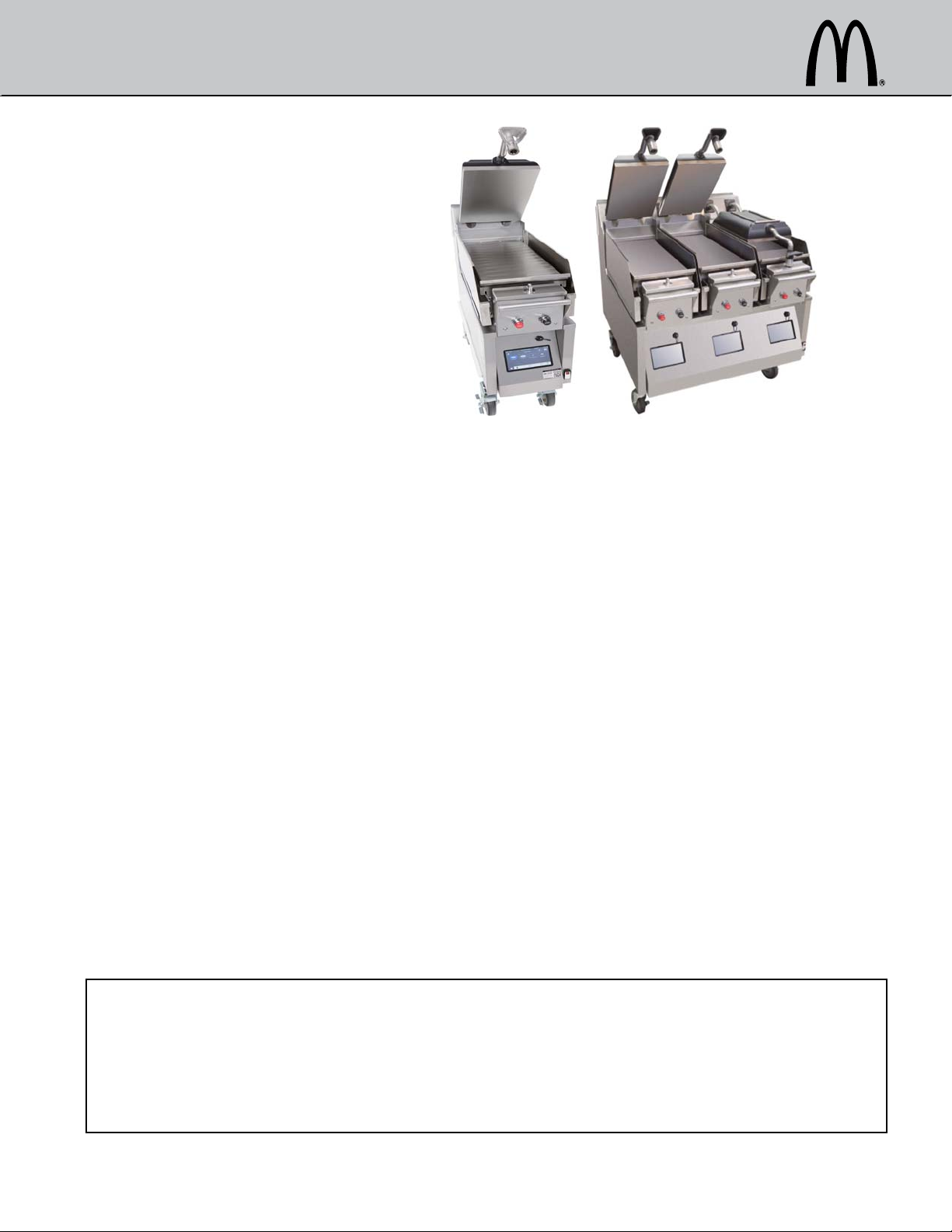
Clamshell Grill
Taylor Models C850, C852, C854, C856, C858, & C860
This equipment chapter is to be inserted
in the appropriate section of the
Equipment Manual.
Manufactured exclusively for
®
McDonald's
Taylor Company
750 N. Blackhawk Blvd.
Rockton, IL 61072
McDonald's® Hotline:
(877-435-7623)
service@taylor-company.com
TABLE OF CONTENTS
Warranty ......................................................................................................................................................... 3
Introduction ..................................................................................................................................................... 3
Safety ................................. ....................................................... ...................................................................... 3
Parts Identification/Function and Exploded View ......... ... .... ... ......................................................................... 6
Important to The Operator ............................................................................................................................ 27
Equipment Setup and Close Procedures ...................................................................................................... 31
Menu Screens ................. ... ... .... ... ... ....................................... ... ... .... ... ... ... .... ................................................ 35
Sausage, Circular Bacon and Patty Placement Guide ................................................................................. 47
Standby Procedures ..................................................................................................................................... 49
Cleaning After Each Run of Product (Using Lower Release Sheets) ........................................................... 49
Cleaning After Each Run of Product (Not Using Lower Release Sheets) ..................................................... 50
Daily Cleaning Procedures (Using Lower Release Sheets) ..... ... ................................................................. 52
Cleaning Procedure-24 Hour Stores (with Lower Release Sheets) .............................................................. 60
Daily Cleaning Procedures (without Lower Release Sheets) ........................................................................ 60
Cleaning Procedure-24 Hour Stores (without Lower Release Sheets) ......................................................... 67
Quarterly Recovery Mode Procedures .......................................................................................................... 67
Troubleshooting Guide .................................................................................................................................. 73
Equipment Troubleshooting .......................................................................................................................... 74
Product Troubleshooting ............................................................................................................................... 75
Limited Warranty on Equipment .................................................................................................................... 76
Limited Warranty on Parts ............................................................................................................................ 78
Ordering/Service Information ........................................................................................................................ 81
By
®
This manual is for the exclusive use of licensees and employees of McDonald's Corporation.
©2006 McDonald's Corporation November, 2006 (Original Publication) Printed in
All Rights Reserved (Updated July, 2019 ) The United States of America
EM SD11
Page 2

Page 3
WARRANTY
Warranty information is contained in this Equipment
Manual. Refer to the warranty information listed in the
Limited Warranty on Equipment and Limited Warranty on
Parts sections and to th e warranty classifications listed in
the Parts Identification/Function section when service is
performed on your machine.
It is recommended that the operator take the necessary
time to carefully read through the complete warranty
information. Thoroughly understand your warranty
protection before you begin operation.
For any questions pertaining to the Taylor Warranty,
please contact Taylor Company, Rockton, Illinois 61072.
INTRODUCTION
Note: These machines are intended to be used for
commercial applications, for example in kitchens of
restaurants, canteens, hospitals, and in commercial
enterprises such as bakeries, butcheries, etc., but not for
continuous mass production of food.
SAFETY
DANGER! Improper installation, adjustment,
alteration, service, or maintenance can cause property
damage, injury, or death. Read the installation, operating,
and maintenance instructions thoroughly before installing
or servicing this machine.
Always follow these safety precautions when operating
the grill:
NOTICE! DO NOT operate this machine
without reading this operator's manual. Failure to comply
may result in machine damage or personal injury. This
manual should be kept in a safe place for future
reference.
The models contained in this Operator’s Manual are the
C850, C852, C854, C856, C858, and C860. The Mod el
C850 is an electric grill with one upper platen. The Model
C852 is an electric grill with two independent upper
platens. The Model C854 is an electric grill with one
upper platen and a shortened lower cooking surface. The
Model C856 is an electric grill with two independent
upper platens and two independent shortened lower
cooking plates. The Model C858/C860 is an electric grill
with three independent upper platens and three
independent lower cooking plates.
These grills provide automatic leveling of the plates.
They are capable of cooking a variety of products and
feature two cooking options, Auto and Manual.
Auto Option: The grills automatically detect the product
placed on the grill plate (menu items that are cooked
double-sided, only) and set the appropriate cooking
parameters.
Manual Option: After the operator selects the desired
product to be cooked, the grills set the appropriate
cooking parameters.
These grills provide all the features of a flat grill, as well
as the advantages of two-sided cooking.
IMPORTANT! This machine is to be used only
by trained personnel. It is not intended for use by children
or people with reduced physical, sensory, or mental
capabilities or lack of experience and knowledge, unless
given supervision or instruction concerning the use of the
machine by a person responsible for their safety.
Children should be supervised to ensure that they do not
play with the machine.
WARNING! DO NOT install the machine in an
area where a water jet could be used. DO NOT use a
water jet to clean or rinse the machine. Failure to follow
this instruction may result in serious electrical shock. In
addition, water may collect inside the machine and
destroy electrical components and cause injury from hot
steam.
WARNING! DO NOT operate this machine
unless it is properly grounded. Failure to comply may
result in equipment damage or personal injury.
3
Page 4
WARNING! All repairs must be performed by
an authorized Taylor service technician. The main power
supplies to the machine must be disconnected prior to
performing any repairs. Failure to comply may result in
equipment damage or personal injury.
These grills are designed for indoor use only.
Note: Only instructions originating from the factory or its
authorized translation representative(s) are considered to
be the original set of instructions.
IMPORTANT! This machine is provided with
an equipotential grounding lug that is to be properly
attached to the rear of the frame by the authorized
installer. The installation location is marked by the
equipotential bonding symbol (5021 of IEC 60417-1) on
the removable panel and the frame.
or not used for long periods, or during initial
installation, shall have protective devices such
as a GFI to protect against the leakage of
current installed by the authorized personn el to
the local codes.
• Supply cords used with this machine shall be
oil-resistant, sheathed flexible cable not lighter
than ordinary polychloroprene or other
equivalent synthetic elastomer-sheathed cord
(code designation 60245 IEC 57) installed with
the proper cord anchorage to relieve conductors
from strain, including twisting, at the terminals
and protect the insulation of the conductors from
abrasion.
If the supply cord is damaged, it must be
replaced by the manufacturer, service agent, or
similarly qualified person, in order to avoid a
hazard.
Failure to follow these instructions may result in severe
injury or death from electrocution.
WARNING! Avoid injury.
• DO NOT operate this machine unless it is
properly grounded.
• DO NOT operate this machine with larger fuses
than specified on the data label.
• DO NOT operate this machine unless all service
panels and access doors are attached with
screws.
• All repairs must be performed by an authorized
Taylor service technician.
• The main power supplies to the machine must
be disconnected prior to performing any repairs.
• Only authorized Taylor service technicians or
licensed electricians may install a plug or
replacement cord on this machine.
• Stationary machines which are not equipped
with a power cord and a plug or other device to
disconnect the machine from the power source
must have an all-pole disconnecting device with
a contact gap of at least 1/8 in. (3 mm) installed
in the external installation.
• Machines that are permanently connected to
fixed wiring and for which leakage currents may
exceed 10 mA, particularly when disconnected
WARNING! This machine must be isolated
from all combustible construction and materials including
but not limited to walls, partitions, furniture, floors,
curtains, paper, boxes, and decorations. Failure to
comply may result in fire and cause destruction and
severe injury.
WARNING! For your safety DO NOT store or
use gasoline or other flammable vapors or liquids in the
vicinity of this or any other machine. Failure to comply
could result in a fire hazard.
IMPORTANT!
• DO NOT obstruct the ventilation openings at the
rear of this machine.
• DO NOT obstruct the flow of air in and around
the machine.
• DO NOT operate this machine unless all service
panels and access doors are attached with
screws.
Failure to comply may result in personal injury from gas
or electrical components.
4
Page 5
CAUTION! Use extreme caution while setting
up, operating, and cleaning the machine to avoid comin g
in contact with hot grill surfaces or with hot grease.
Failure to comply may result in burn injuries.
CAUTION! The machine must be placed on a
level surface.
• To ensure thorough cleaning, the machine must
be pulled away from the wall. When pulling the
machine away from the wall for cleaning and
before returning the grill to its original position,
first always check to ensure that all four casters
are aligned and parallel with the machine from
front to back and that the lock nuts are tight. If
the casters are properly aligned, unlock the front
casters and use care to smoothly and slowly roll
the machine into or out of place. (Do not lift.) If
there is a discontinuity in the floor, use extra
care to ensure that the machine remains as
level as possible from side to side. Failure to do
so may cause the machine to tip, leading to
machine damage or personal injury. When
returning the machine to its original position,
use extreme caution to smoothly and slowly roll
the machine back into place and lock the front
casters.
Failure to follow these instructions may cause the grill to
tip and can result in severe equipment damage or
personal injury.
NOTICE! The procedure(s) in this manual
include the use of chemical products. These chemical
products will be highlighted with boldface letters followed
by the abbreviation HCS in the text portion of the
procedure. See the Hazard Communication Standard
(HCS) manual for the appropriate Material Safety Data
Sheet(s) (MSDS).
This machine is made using USA sizes of hardware. All
metric conversions are approximate.
Noise Level: Airborne noise emission does not exceed
70 dB(A) when measured at a distance of 39 in. (1.0 m)
from the surface of the machine and at a height of 62 in.
(1.6 m) from the floor.
IMPORTANT! If the crossed-out waste
container symbol is affixed to this machine, it signifies
that this machine is compliant with the EU Directive as
well as other similar legislation in effect after August 13,
2005. Therefore, it must be collected separately after its
use is completed and cannot be disposed as unsorted
municipal waste. The user is responsible for delivering
the product to the appropriate collection facility, as
specified by your local code.
For additional information regarding applicable local
laws, please contact the municipal facility and/or local
distributor.
NOTICE! All warning labels that have been
attached to the machine point out safety precautions to
the operator.
5
Page 6
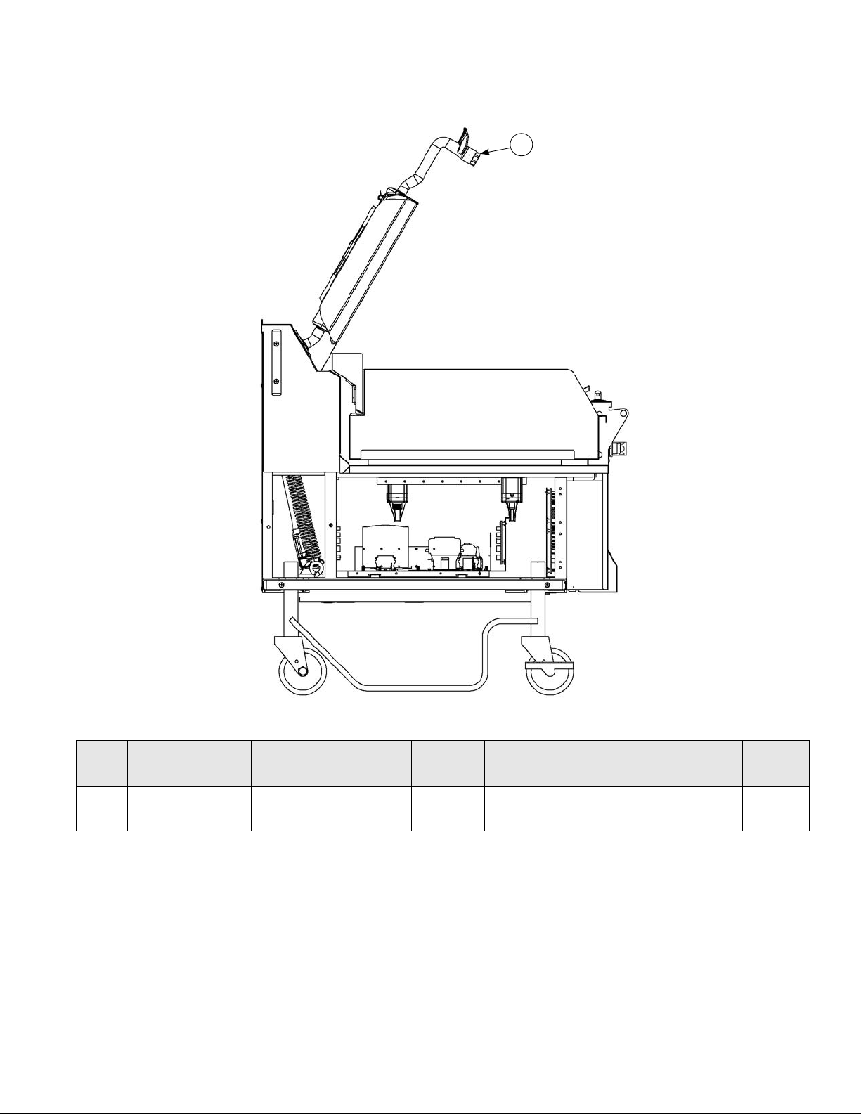
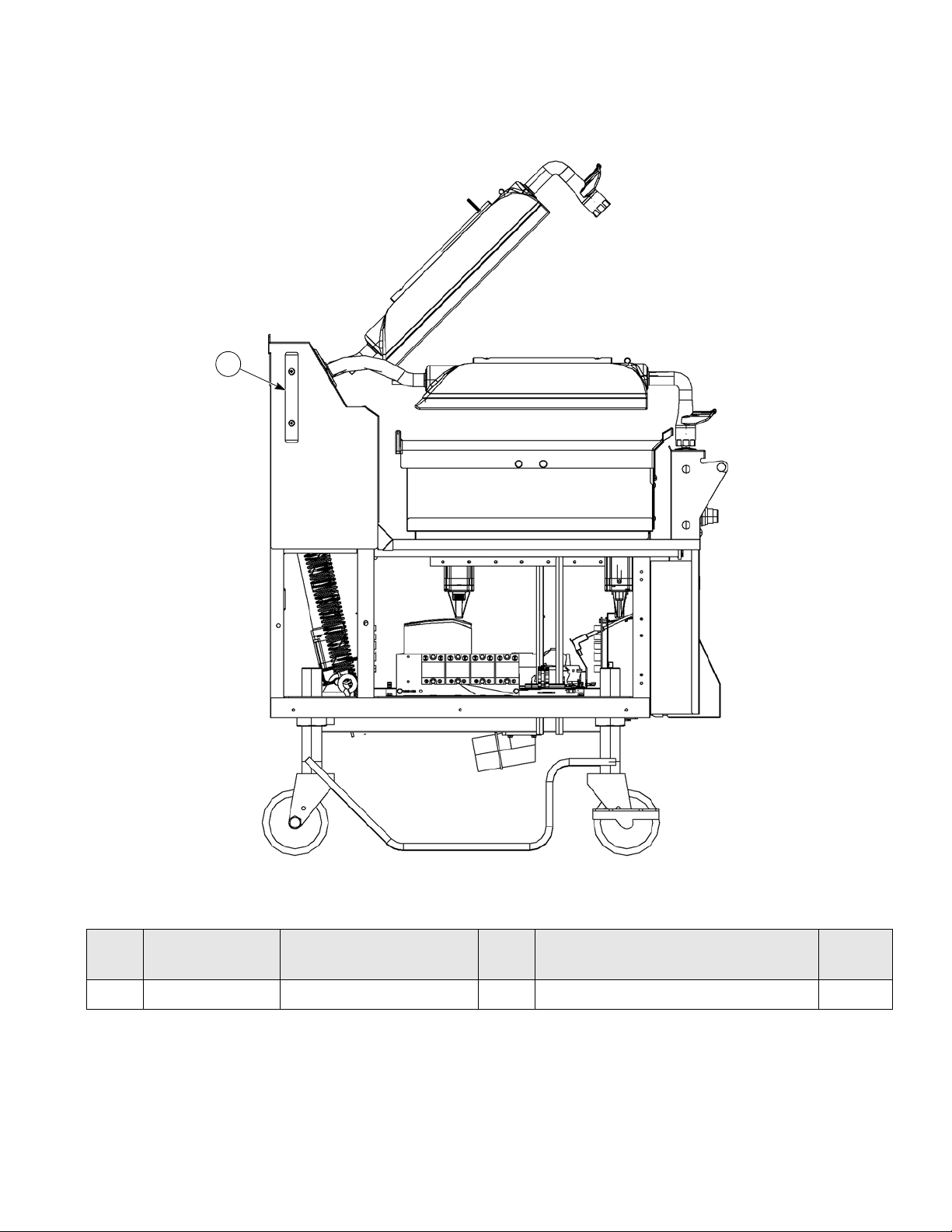
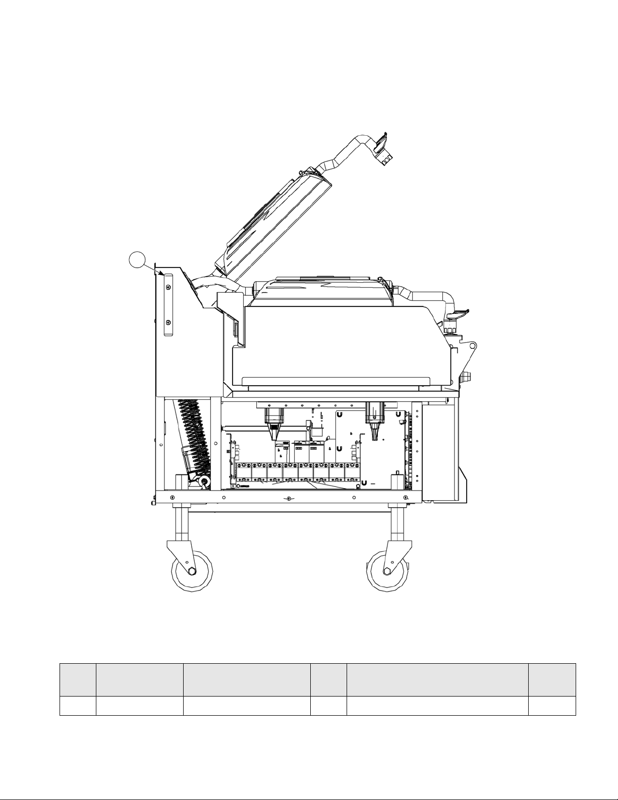
C850 Exploded View
1
2
24
3
4
5
6
7
10
8
8
15
9
14
3
13
17
16
18
19
20
21
22
23
25
4
26
11
12
12
27
PARTS IDENTIFICATION/FUNCTION AND EXPLODED VIEW
Figure-1
6
Page 7

C850 Exploded View
Item Part No. Description Qty. Function
1 X84969 Can A.-Grease-L 1 Container for grease. 103
2 X84224 Shroud-Upper Side 1 Metal bracket that the grease can slides
into, securing it next to the lower grill plate.
3 X84325 Shroud A. - Lower - Left 2 Left/right access panel. 103
4 070695 Screw-10-32X1/2 Phil 4 Fastens bumpers to panels. 000
5 084549 Bumper 2 Protects grill from damage. 000
6 X73600-SER Kit A.-Grease Shield 2 Fastens grease shields to rear shroud. 000
7 082959 Panel-Rear 1 Provides access to internal components for
service and cleaning.
8 024298 Screw-10-32X3/8 Phil 34 Secures the panel to the frame. 000
9 X84225 Shroud A.-Upper -Right 1 Metal bracket that the grease can slides
into, securing it next to the lower grill plate.
10 X84608 Can A.-Grease-R 1 Container for grease. 103
11 027408 Screw-10-32X1/4 SLTD Truss Secures the panels to the frame.
12 082958 Panel-Side-Right 1 Provides access to internal components for
service and cleaning.
13 078377-1 Caster-5 7-5/8 Stem 2 Allows grill mobility. 103
14 086984-1 Outrigger A.-Right 1 Stabilizes grill. 000
15 087002 Pin-Cotter 1/8 x 1 in. 8 Secures the outrigger to the caster. 000
Warr.
Class
103
103
103
103
16 073240-3 Caster-5 7-5/8 Stem-Swivel w/
Lock
17 086985-1 Outrigger-Left 1 Stabilizes grill. 000
18 076989-WP Switch-Rocker- DPST 10A 1 Activates power to the grill and the exhaus t
19 X84230 Door A.-Control 1 Houses the controls. 103
20 X85623-SER Touchscreen A. 1 Controls all functions of the grill. - - 21 068583 Cover A.-USB Waterproof 1 Protects USB port from water damage. 103
22 076012 Button-Operator-Black 1 Activates the Cook cycle, keeps the upper
23 076011 Button-Operator-
Red
24 X85465 Shield A.-Rear GRS 1 Prevents grease migration. 000
25 082957 Panel-Side-Left 1 Provides access to internal components for
26 085447 Spacer Bumper 1 Protects grill from damage. 000
27 084613 Bumper 1 Protects grill from damage. 000
2 Prevents grill movement when the brake is
used.
fans.
platen in the closed position, and displays
STANDBY on the control. When pressed
twice with 1-second intervals between
presses, the upper platen will automatically
lower into the Standby position.
1 Cancels Standby mode, raises the upper
platen, and deactivates the Cook cycle.
service and cleaning.
103
103
000
000
103
7
Page 8
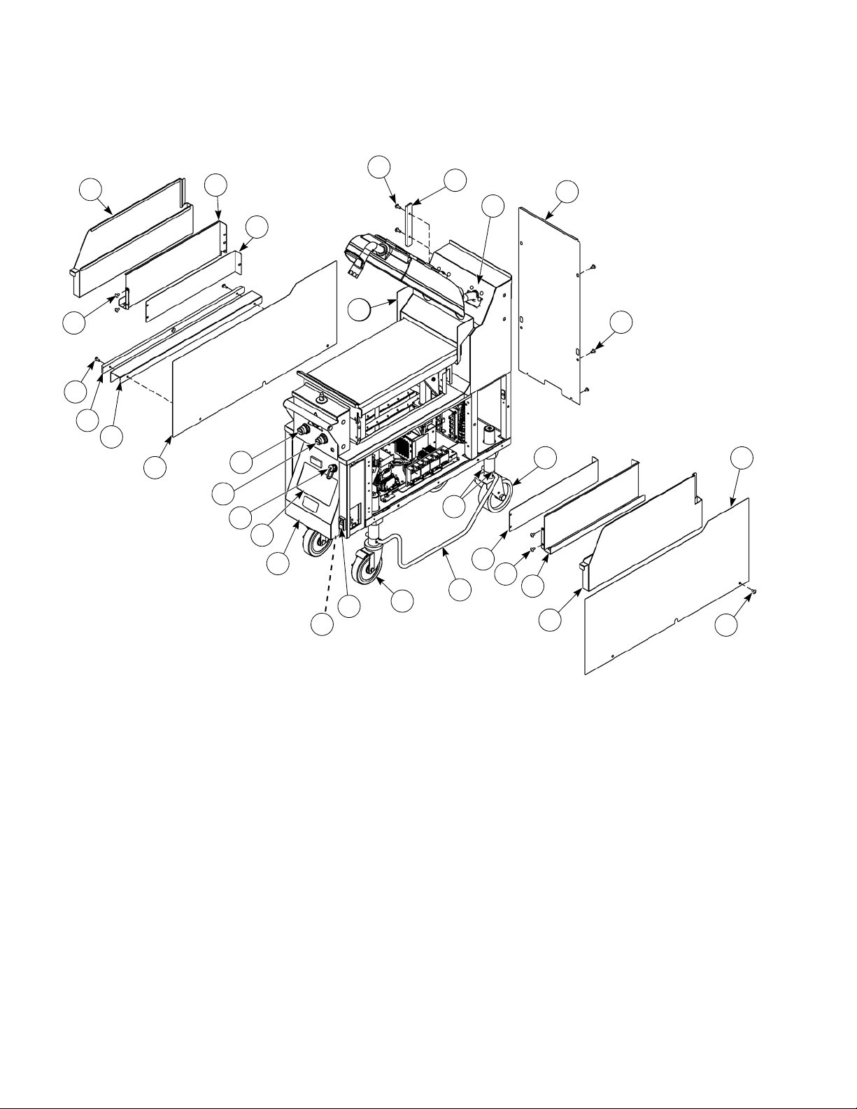
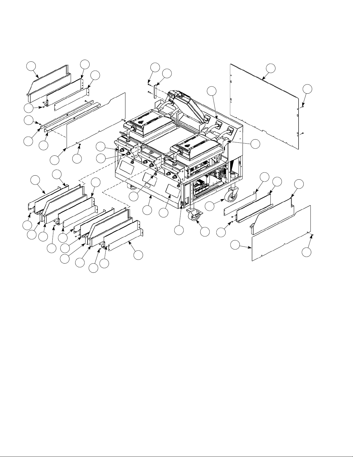
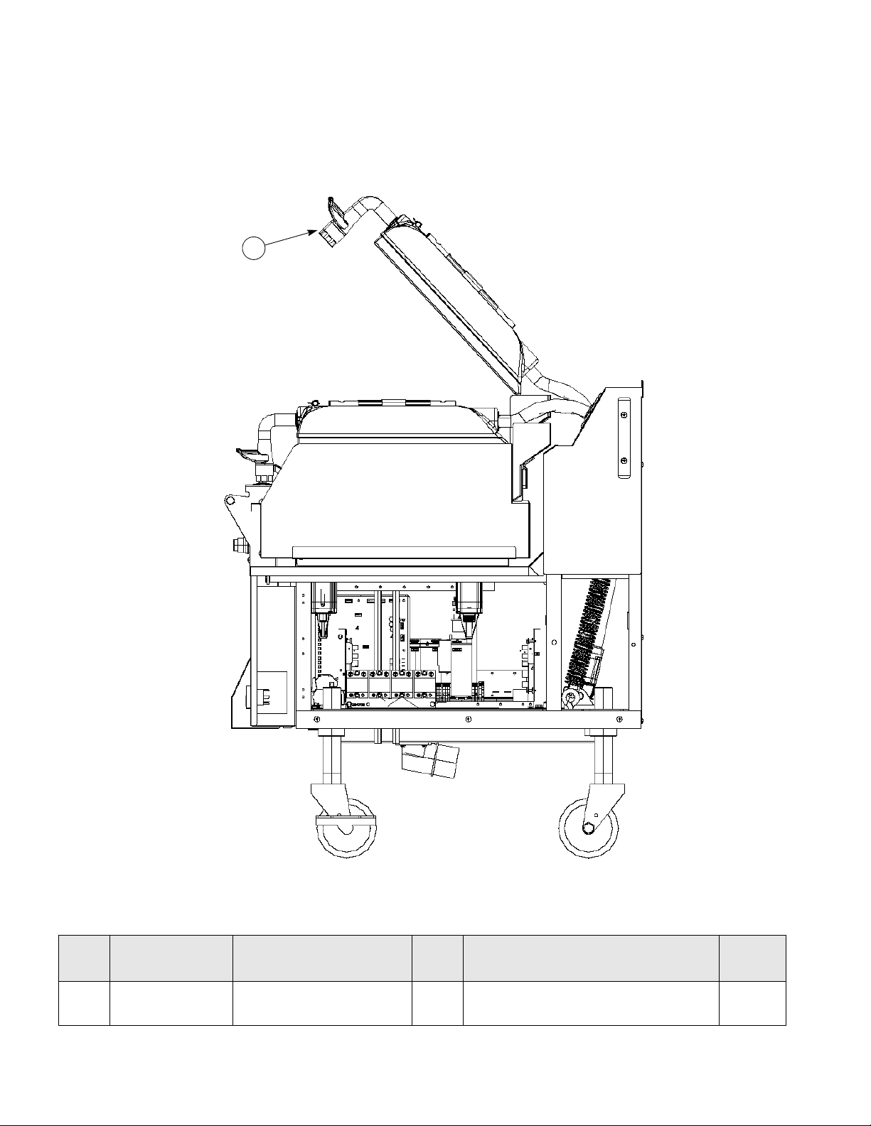
C852 Exploded View
27
2
4
5
7
6
9
10
9
11
13
12
14
15
16
17
18
19
20
21
22
23
25
26
1
3
8
1
4
4
3
2
4
13
14
1
1
24
Figure-2
8
Page 9
C852 Exploded View
Item Part No. Description Qty. Function
1 027408 Screw-10-32X1/4 SLTD Truss 16 Secures the panels to the frame. 000
2 X84969 Can A.-Grease-L 2 Container for grease. 103
3 X84224 Shroud A.-Upper*LFT 2 Metal bracket that the grease can slides into,
securing it next to the lower grill plate.
4 X84325 Shroud A. - Lower - Left 4 Left/right access panel. 103
5 070695 Screw-10-32X1/2 PHIL 4 Fastens bumper onto panel. 000
6 084549 Bumper 1 Protects grill from damage. 000
7 X73600-SER Kit A.-Grease Shield 4 Fastens grease shields to rear shroud. 000
8 084215 Panel-Rear 1 Provides access to internal components for
service and cleaning.
9 024298 Screw-10-32X3/8 SLTD Truss 54 Secures the panel to the frame. 000
10 082958 Panel-Side-Right 1 Provides access to internal components for
service and cleaning.
11 078377 Caster-5 7-5/8 Stem 2 Allows grill mobility. 103
12 X84608 Can A.-Grease-R 2 Container for grease. 103
13 X84225 Shroud A.-Upper-Right 2 Metal bracket that the grease can slides into,
securing it next to the lower grill plate.
14 073240 Caster-5 7-5/8 Swivel w/Lock 2 Prevents grill movement when the lock is used. 103
Warr.
Class
103
103
103
103
15 076989-WP Switch-Rocker- DPST 10A 1 Activates power to the grill and the exhaust
fans.
16 X84265-23 Control A.-Right 1 Controls all functions of the grill. - - 17 X85623-SER Touchscreen A. 1 Controls all functions of the grill. - - 18 X84255 Door A.-Welded 2 Houses the controls and the fan interlock
switch.
19 068583 Cover A.-USB Waterproof 2 Protects USB port from water damage. 103
20 076012 Button-Operator- Black 2 Activates the Cook cycle, keeps the upper
platen in the closed position, and displays the
message STANDBY on the control. When
pressed twice with 1-second intervals between
presses, the upper platen will automatically
lower into the Standby position.
21 076011 Button-Operator- Red 2 Cancels the Standby mode, raises the upper
platen, and deactivates the Cook cycle.
22 079150 Nut-10-32 Whiz Flange Lock 2 Secures the spacer to the bumper. 000
23 082957 Panel-Side-Left 1 Provides access to internal components for
service and cleaning.
24 085447 Space Bumper 1 Protects grill from damage. 000
25 084613 Bumper 1 Protects grill from damage. 000
103
103
000
000
103
26 033944 Screw-10-32x3/4 SLTD Truss 2 Secures the spacer to the bumper. 000
27 X85465 Shield A.-Rear-GRS 2 Prevents grease migration. 000
9
Page 10
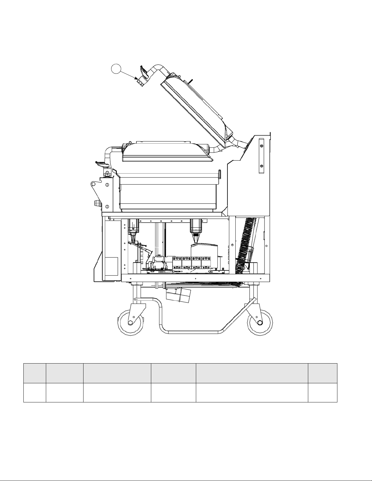
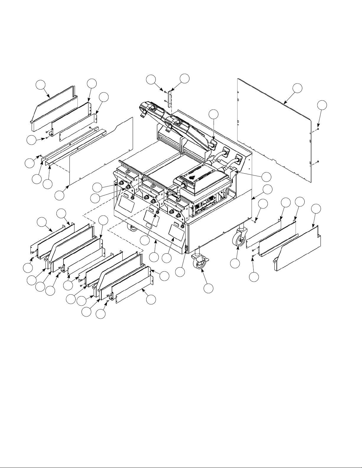
C850/C852 Right Side View
1
Figure-3 (C850 shown)
Item Part No. Description Qty. Function
1 X84169-SER Kit A.-Actuator Plate 3 (C850)
6 (C852)
Positions the cooking surface. 103
10
Warr.
Class
Page 11
C850/C852 Left Side View
1
Figure-4 (C850 shown)
Item Part No. Description Qty. Function
1 X85715 Handle A.-Align Ring 1 (C850)
2 (C852)
The handle clicks in to the platen latch
when in the down position.
Warr.
Class
000
11
Page 12
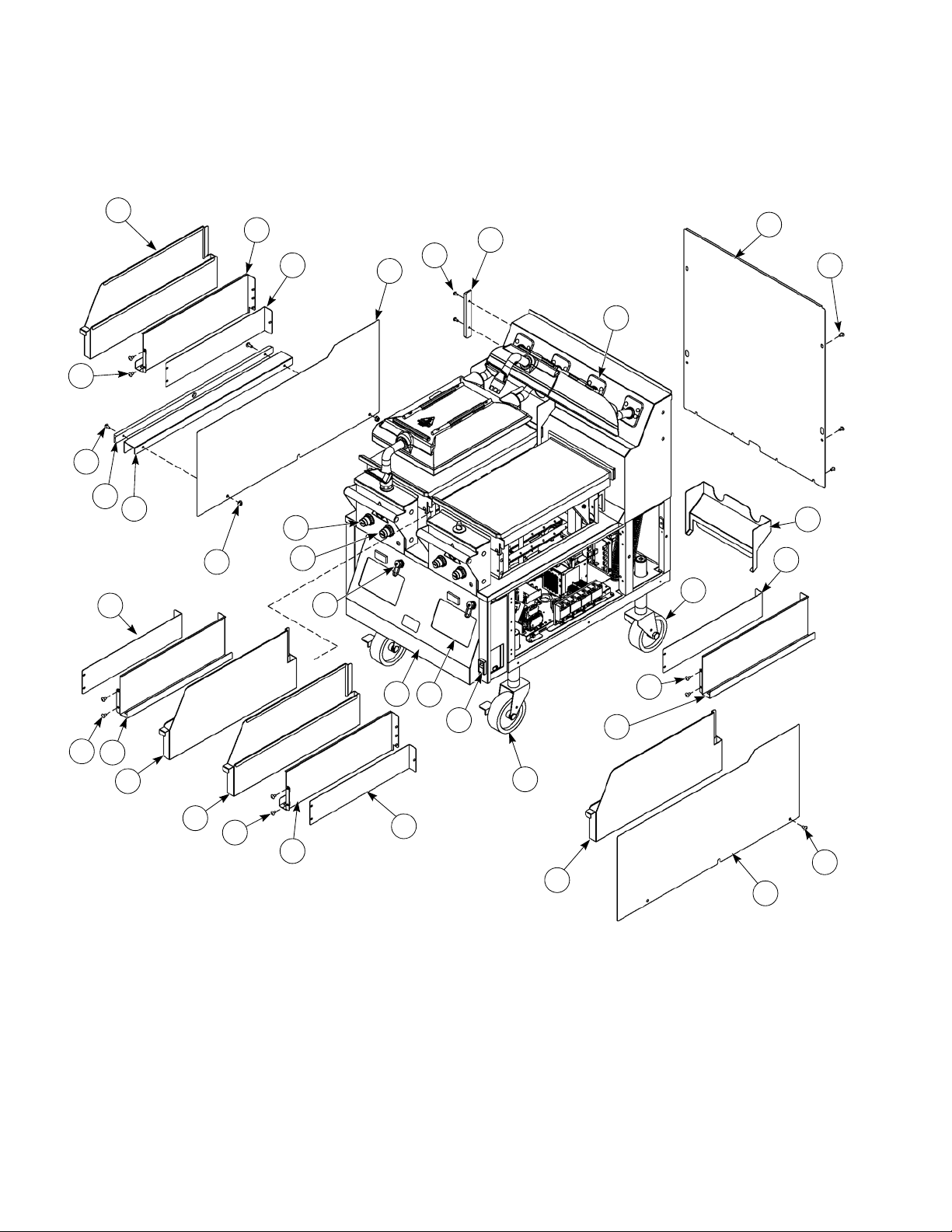
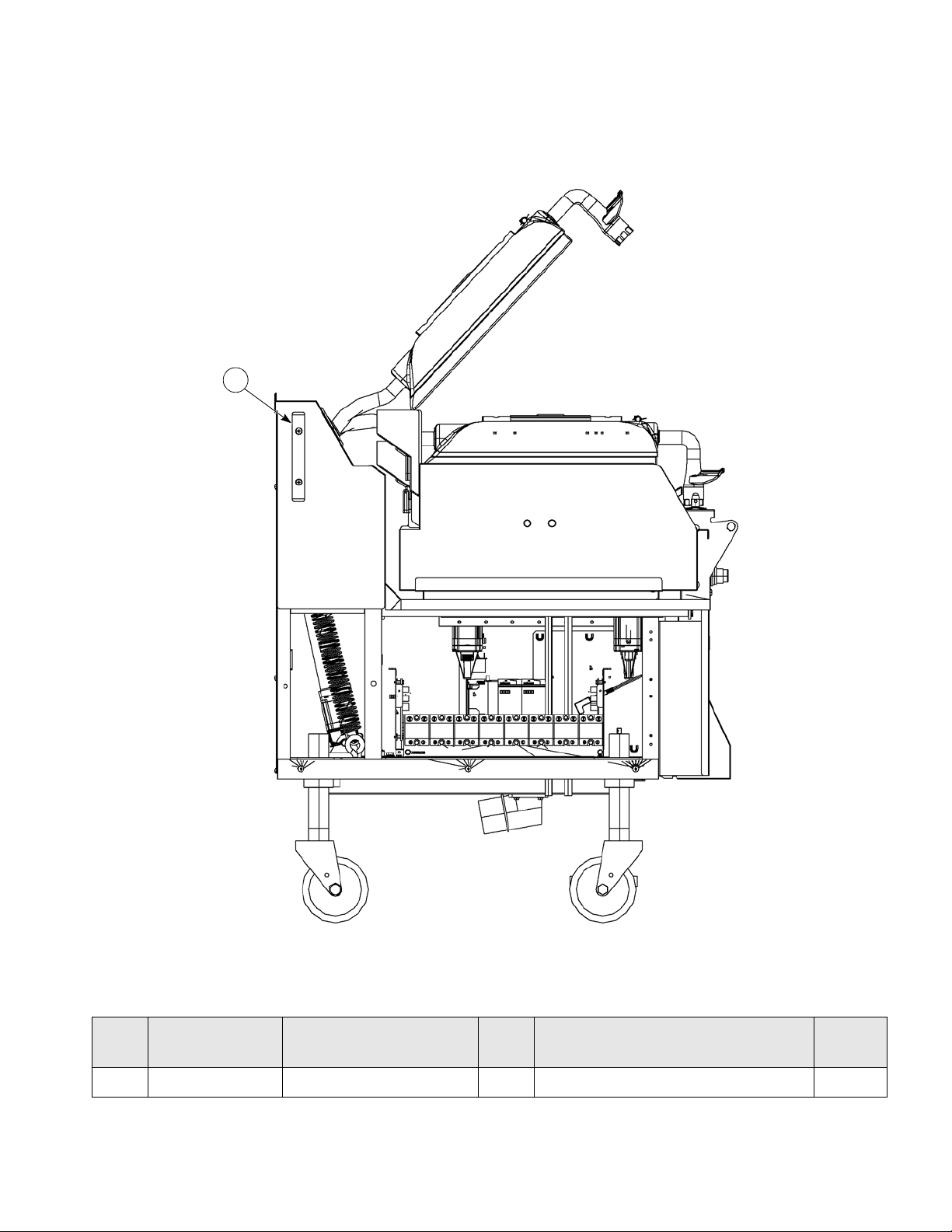
C854 Exploded View
1
24
2
3
4
6
5
11
9
9
12
10
15
14
17
18
19
20
21
22
23
25
26
5
27
1
4
13
16
7
8
Figure-5
12
Page 13

C854 Exploded View
Item Part No. Description Qty Function
1 027408 Screw-10-32X1/4 SLTD Truss 8 Secures the panels to the frame. 000
2 X84971 Can A.-Grease-L 1 Container for grease. 103
3 X84248 Shroud A.-Upper*LFT 1 Metal bracket that the grease can slides
into, securing it next to the lower grill plate.
4 X84323 Shroud A. - Lower - Side 2 Left/right access panel. 103
5 070695 Screw-10-32X1/2 PHIL 4 Fastens bumper onto panel. 000
6 084549 Bumper 1 Protects grill from damage. 000
7 X73600-SER Kit A.-Grease Shield 4 Fastens grease shields to rear shroud. 000
8 082959 Panel-Rear 1 Provides access to internal components for
service and cleaning.
9 024298 Screw-10-32X3/8 SLTD Truss 54 Secures the panel to the frame. 000
10 084250 Panel-Side-Right 1 Provides access to internal components for
service and cleaning.
11 X84526 Can A.-Grease-R 1 Container for grease. 103
12 X84246 Shroud A.-Upper*RT 1 Metal bracket that the grease can slides
into, securing it next to the lower grill plate.
13 078377-1 Caster-5 7-5/8 Stem 2 Allows grill mobility. 103
14 087002 Pin-Cotter 1/8 x 1 in. 8 Secures the outrigger to the caster. 000
15 086984 Outrigger A.-Right 1 Stabilizes grill. 000
16 073240-3 Caster-5 7-5/8 Stem-Swivel w/
Lock
17 076989-WP Switch-Rocker- DPST 10A 1 Activates power to the grill and the exhaust
18 086985 Outrigger-Left 1 Stabilizes grill. 000
19 X84523 Door A.-Lower 1 Controls all functions of the grill. - - 20 X85623-SER Touchscreen A. 1 Controls all functions of the grill. - - 21 068583 Cover A.-USB Waterproof 2 Protects USB port from water damage. 103
22 076012 Button-Operator- Black 2 Activates the Cook cycle, keeps upper
23 076011 Button-Operator- Red 2 Cancels the Standby mode, raises the upper
24 X85465 Shield A.-Rear-GRS 2 Prevents grease migration. 000
25 084251 Panel-Side-Left 1 Provides access to internal components for
26 085441 Spacer Bumper 1 Protects grill from damage. 000
27 084550 Bumper 1 Protects grill from damage. 000
2 Prevents grill movement. 103
fans.
platen in the closed position, and displays
the message STANDBY on the control.
When pressed twice with 1-second intervals
between presses, the upper platen will
automatically lower into STANDBY position.
platen, and deactivates the Cook cycle.
service and cleaning.
Warr.
Class
103
103
103
103
103
000
000
103
13
Page 14
C856 Exploded View
2
5
4
9
7
10
11
12
14
10
16
17
19
18
4
1
20
21
22
23
24
3
1
6
8
15
4
1
13
2
3
15
16
1
4
26
25
Figure-6
14
Page 15

C856 Exploded View
Item Part No. Description Qty Function Warr. Class
1 027408 Screw-10-32X1/4 SLTD Truss 16 Secures the panels to the frame. 103
2 X84971 Can A.-Grease-L 2 Container for grease. 103
3 X84248 Shroud A.-Upper*L 2 Metal bracket that the grease can slides
into, securing it next to the lower grill plate.
4 X84323 Shroud A. - Lower - Side 4 Left/right access panel. 103
5 084251 Panel-Side-Left 1 Provides access to internal components for
service and cleaning.
6 070695 Screw-10-32X1/2 Phil 4 Fastens bumper onto panel. 000
7 084549 Bumper 1 Protects grill from damage. 000
8 X73600-SER Kit A.-Grease Shield 4 Fastens grease shields to rear shroud. 000
9 084215 Panel-Rear 1 Provides access to internal components for
service and cleaning.
10 024298 Screw-10-32X3/8 SLTD Truss 54 Secures the panel to the frame. 000
11 X85465 Shield A.Rear GRS 2 Prevents grease migration.
12 078377 Caster-5 7-5/8 Stem 2 Allows grill mobility. 103
13 084250 Panel-Side-Right 1 Provides access to internal components for
service and cleaning.
14 X84526 Can A.-Grease-R 2 Container for grease. 103
15 X84246 Shroud A.-Upper*R 2 Metal bra c ket that the grease can slides
into, securing it next to the lower grill plate.
16 073240 Caster-5 7-5/8 Swivel w/Lock 2 Prevents grill movement. 103
17 076989-WP Switch-Rocker- DPST 10A 1 Activates power to the grill and the exhaust
fans.
18 X85623-SER Touchscreen A. 2 Controls all functions of the grill. - - 19 X84504 Door A.-Welded 1 Houses the controls and the fan interlock
switch.
20 068583 Cover A.-USB Waterproof 2 Protects USB port from water damage. 103
21 076012 Button-Operator- Black 2 Activates the cook cycle, keeps the upper
platen in the closed position, and displays
the message STANDBY on the control.
When pressed twice with 1-second intervals
between presses, the upper platen will
automatically lower into the Standby
position.
22 076011 Button-Operator- Red 2 Cancels the Standby mode, raises the upper
platen, and deactivates the Cook cycle.
23 079150 Nut-10-32 Whiz Flange Nut 2 Secures the spacer to the bumper. 000
24 085441 Spacer Bumper 1 Protects grill from damage. 000
25 084550 Bumper 1 Protects grill from damage. 000
26 033944 Screw-10-32x3/4 SLTD Truss 2 Secures the spacer to the bumper. 000
103
103
103
103
103
103
103
000
000
15
Page 16
C854/C856 Right Side View
1
Figure-7 (C854 with outrigger shown)
Item Part No. Description Qty. Function
1 X85716 Handle A.-Align Ring 1 (C854)
2 (C856)
16
The handle clicks in to the platen latch
when in the down position.
Warr.
Class
103
Page 17
C854/C856 Left Side View
1
Figure-8 (C854 with outrigger shown)
Item Part No. Description Qty. Function
1 084549 Bumper 1 Protects the grill from damage. 000
Warr.
Class
17
Page 18
C858 Exploded View
1
2
3
4
8
9
10
12
4
7
14
11
13
15
16
17
1
18
19
23
24
26
25
6
5
7
20
21
4
4
2
12
11
2
1
3
4
11
1
1
12
3
22
Figure-9
18
Page 19

C858 Exploded View
Item Part No. Description Qty. Function
1 027408 Screw-10-32X1/4 SLTD Truss 24 Secures the panels to the frame. 103
2 X84969 Can A.-Grease-L 3 Container for grease. 103
3 X84224 Shroud A.-Upper*L 3 Metal bracket that the grease can slides into,
securing it next to the lower grill plate.
4 X84325 Shroud A. - Lower - L 6 Left/right access panel. 103
5 070695 Screw-10-32X1/2 Phil 4 Fastens bumper onto panel. 000
6 084549 Bumper 1 Protects grill from damage. 000
7 X73600-SER Kit A.-Grease Shield 6 Fastens grease shields to rear shroud. 000
8 085963 Panel-Rear 1 Provides access to internal components for
service and cleaning.
9 024298 Screw-10-32X3/8 SLTD Truss 54 Secures the panel to the frame. 000
10 X85465 Shield A.-Rear GRS 3 Prevents grease migration.
11 X84608 Can A.-Grease-R 3 Container for grease. 103
12 X84225 Shroud A.-Upper*R 3 Metal brac ket that the grease can slides into,
securing it next to the lower grill plate.
13 082958 Panel-Side-Right 1 Provides access to internal components for
service and cleaning.
14 078377 Caster-5 7-5/8 Stem 2 Allows grill mobility. 103
15 073240 Caster-5 7-5/8 Swivel w/Lock 2 Prevents grill movement. 103
Warr.
Class
103
103
103
103
16 076989-WP Switch-Rocker- DPST 10A 1 Activates power to the grill and the exhaust fans. 103
17 X85623-SER Touchscreen A. 3 Controls all functions of the grill. - - 18 X85931 Door A.-Welded 1 Houses controls and the fan interlock switch. 103
19 068583 Cover A.-USB Waterproof 3 Protects USB port from water damage. 103
20 076012 Button-Operator- Black 3 Activates the Cook cycle, keeps the upper platen
in the closed position, and displays the message
STANDBY on the control. When pressed twice
with 1-second intervals between presses, the
upper platen will automatically lower into the
Standby position.
21 076011 Button-Operator- Red 3 Cancels the Standby mode, raises the upper
platen, and deactivates the Cook cycle.
22 079150 Nut-10-32 Whiz Flange Nut 2 Secures the spacer to the bumper. 000
23 082957 Panel-Side-Left 1 Provides access to internal components for
service and cleaning.
24 085447 Spacer Bumper 1 Protects grill from damage. 000
25 084613 Bumper 1 Protects grill from damage. 000
26 033944 Screw-10-32x3/4 SLTD Truss 2 Secures the spacer to the bumper. 000
000
000
103
19
Page 20
C860 Exploded View
1
2
3
4
7
8
5
6
13
12
9
14
10
1
15
16
17
18
1
2
13
20
21
2
23
24
22
10
4
19
25
4
3
12
4
1
4
13
12
3
1
11
Figure-10
20
Page 21

C860 Exploded View
Item Part No. Description Qty. Function
1 027408 Screw-10-32X1/4 SLTD Truss 24 Secures the panels to the frame. 103
2 X84971 Can A.-Grease-L 3 Container for grease. 103
3 X84248 Shroud A.-Upper*L 3 Metal bracket that the grease can slides into,
securing it next to the lower grill plate.
4 X84323 Shroud A. - Lower - Side 6 Left/right access panel. 103
5 070695 Screw-10-32X1/2 Phil 4 Fastens bumper onto panel. 000
6 084549 Bumper 1 Protects grill from damage. 000
7 X73600-SER Kit A.-Grease Shield 6 Fastens grease shields to rear shroud. 000
8 X85465 Shield A.-Rear GRS 3 Prevents grease migration.
9 085963 Panel-Rear 1 Provides access to internal components for
service and cleaning.
10 024298 Screw-10-32X3/8 SLTD Truss 54 Secures the panel to the frame. 000
11 084250 Panel-Side-Right 1 Provides access to internal components for
service and cleaning.
12 X84526 Can A.-Grease-R 3 Container for grease. 103
13 X84246 Shroud A.-Upper*R 3 Metal brac ket that the grease can slides into,
securing it next to the lower grill plate.
14 078377 Caster-5 7-5/8 Stem 2 Allows grill mobility. 103
15 073240 Caster-5 7-5/8 Swivel W/Lock 2 Prevents grill movement. 103
Warr.
Class
103
103
103
103
16 076989-WP Switch-Rocker- DPST 10A 1 Activates power to the grill and the exhaust fans. 103
17 X85623-SER Touchscreen A. 3 Controls all functions of the grill. - - 18 X85761 Door A.-Welded 1 Houses controls and the fan interlock switch. 103
19 068583 Cover A.-USB Waterproof 3 Protects USB port from water damage. 103
20 076012 Button-Operator- Black 3 Activates the Cook cycle, keeps the upper platen
in the closed position, and displays the message
STANDBY on the control. When pressed twice
with 1-second intervals between presses, the
upper platen will automatically lower into the
STANDBY position.
21 076011 Button-Operator- Red 3 Cancels the Standby mode, raises the upper
platen, and deactivates the Cook cycle.
22 084251 Panel-Side-Left 1 Provides access to internal components for
service and cleaning.
23 085447 Spacer Bumper 1 Protects grill from damage. 000
24 084613 Bumper 1 Protects grill from damage. 000
25 033944 Screw-10-32x3/4 SLTD Truss 2 Secures the spacer to the bumper. 000
000
000
103
21
Page 22
C858 Right Side View
1
Figure-11
Item Part No. Description Qty. Function
1 X85715 Handle A.-Align Ring
22
The handle clicks in to the platen latch
3
when in the down position.
Warr.
Class
103
Page 23
C858 Left Side View
1
Figure-12
Item Part No. Description Qty. Function
1 084549 Bumper 1 Protects the grill from damage. 000
Warr.
Class
23
Page 24
C860 Right Side View
1
Figure-13
Item Part No. Description Qty. Function
1 X85715 Handle A.-Align Ring
24
The handle clicks in to the platen latch
3
when in the down position.
Warr.
Class
103
Page 25
C860 Left Side View
1
Figure-14
Item Part No. Description Qty. Function
1 084549 Bumper 1 Protects the grill from damage. 000
Warr.
Class
25
Page 26
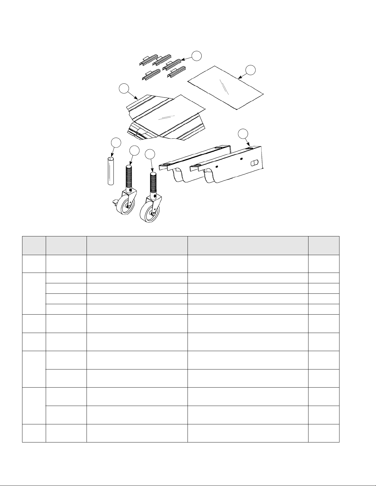
Accessories
1
4
2
6
5
7
3
Figure-15
Item Part No. Description Function
1 072673 Clip-Release Material-w/Tab Secures the release material to the front and
sides of the platen.
X85752 Kit A.-Caster Guard (C850) Protects the power cord. 000
X85753 Kit A.-Caster Guard (C852/C858) Protects the power cord. 000
*2
X85754 Kit A.-Caster Guard (C854) Protects the power cord. 000
X85756 Kit A.-Caster Guard (C856/C860) Protects the power cord. 000
3 084366 Sheet-Release
**4 084387 Sheet-Lower Release
073240-3 Caster-5" 7-5/8 Swivel w/Lock
5
073240 Caster-5" 7-5/8 Swivel w/Lock
078377-1 Caster-5" 7-5/8 Stem Rigid
6
078377 Caster-5" 7-5/8 Stem Rigid
7 084814 Cover-Caster Thread
Box of 3
Box of 3
(C850/C854 Only)
(C852/C856/C858/C860)
(C850/C854)
(C852/C856/C858/C860)
(C850/C854)
Non-stick barrier used to protect the upper
platen.
Non-stick barrier used to protect the lower cook
surface.
Prevents grill movement. 000
Prevents grill movement. 000
Allows grill mobility. 000
Allows grill mobility. 000
Protects the caster thread. 000
Warr.
Class
000
000
000
*Optional–Purchased separately **For markets using lower release sheets only.
26
Page 27

IMPORTANT TO THE OPERATOR
1
2
3
4
5
6
7
8
9
19
18
17
16 15 14
13
12 11
10
20
21
22
22
23
24
Figure-16
27
Page 28

Important to the Operator Exploded View
Item Description Function
1 F an Interlock Switch Activates power to the grill and the exhaust fa ns.
2 Clean Key Takes the grill into the ready mode for cleaning.
3 Settings Key Displays a passcode screen to allow the manager to enter the
passcode and enter the Manager’s Menu. From the
Manager’s Menu, the manager can make adjustments to the
Date/Time, Temperature Scale, Volume, Brightness,
Language, and Firmware Manager functions.
4 Cook Time Key Allows the user to set the Cook Time.
5 Recipe Filter Key Allows the user to choose the grill mode (auto or manual) and
toggle between AM, PM, and ALLDAY modes.
6 Date/Time Key Allows the user to enter the date and time of day.
7 General Key Displays the Temperature Scale, Firmware, and About
screens.
8 Display Key Displays the Brightness and Font Limit screens.
9 Auto Calibrate Key Allows the user to Auto Calibrate and Gap Check.
10 Help Key Future development.
11 Menu Key Displays the main screen.
12 Back Arrow Key Returns the user to the previous screen.
13 Recipe Management Key Allows the user to choose a product.
14 Power Key Takes the user to another screen to turn the grill controller off.
15 Language Key Selects the desired language.
16 Volume Key Selects the desired volume.
17 Notification/Warning Key Displays the recent faults and events.
18 Information Key Displays current status of machine (examples: temperatures
of upper platens and lower cook surfaces, date when last
cleaning was performed.
19 Home Key Enters the main menu.
20 Cook Time Shortcut Key Allows the user to jump to the Cook Time key from the Home
screen.
21 Temperature Calibration Key Allows the user to calibrate temperatures of specified areas
on the grill.
22 Recipe Key Allows the user to choose a product.
23 AM/PM Shortcut Key Allows the user to jump to the AM/PM key from the Home
screen.
24 Manual Shortcut Key Allows the user to jump to the Manual key from the Home
screen.
28
Page 29

Other Symbol Definitions
To better communicate in the international arena, the words on many of our operator keys have been replaced by
symbols to indicate their functions. Your Taylor equipment is designed with these international symbols.
The following chart identifies the symbol definitions.
ON Key–Activates and deactivates
the grill control.
Home Key–Returns you to the actions required
screen.
Information Key–Displays the current status of
the machine (examples: temperatures of upper
platens and lower cook surfaces, date when the
last cleaning was performed, and date when the
last product integrity was performed.)
Notification Key (gray)–No active alert or
warning.
Warning Key (orange)–Displays the recent
faults and events.
Alarm Key (red)–Displays the recent faults and
events. Highest level of concern.
Notification Key (yellow)–Displays the recent
faults and events. Concerns that are not urgent.
(Full) Clean Key–Takes the grill into the ready
mode for cleaning.
Auto Calibrate Key–Allows the user to auto
Calibrate and Gap Check.
Settings Key–Displays a passcode screen to
allow the manager to enter the passcode and
enter the Manager Menu. From the Manager
Menu, the manager can make adjustments to
the Date/Time, Temperature, Scale, Volume,
Brightness, Language, and Firmware Manager
functions.
Training Key–Displays steps on how to perform
various actions.
About Key–Displays information regarding
model, bill of material, Store I.D., and IP
address.
Date/Time Key–Allows the user to enter the
date and time of day.
Date Key–Displays the current date.
Alert Key (red)–Displays the recent faults and
events. Highest level of concern.
Back Arrow Key–Returns the user to the
previous screen.
Help Key–Content details of current screen.
Future development
Menu Key–Displays list of available
actions in the grill.
Checkmark Key–Acknowledges the
changes completed.
Time Key–Actual time is displayed and allows
the user to update the time.
Scale Key–Allows the user to select Celsius or
Fahrenheit.
Celsius Key–Display will be blue if in Celsius
format.
Fahrenheit Key–Display will be blue if in
Fahrenheit format.
Not Calibrated Key
29
Page 30

Other Symbol Definitions
X Key–Do not save current changes. Exits
current screen.
Auto Calibrate Key–Pressing this key will
calibrate the gaps. Also in Info screen displaying
status.
Grill Mode Key–Allows the user to toggle
between Manual and Auto. Also represents the
Manual Mode.
Firmware Manager Key–Allows the user to
update software.
Brightness Key–Displays the current
brightness setting and allows the user to change
the brightness level.
Gap Check Key–Moves the lower platen to a
defined gap.
Recipes Key–Functions associated with
recipes.
Recipe Filter Key–Allows the user to choose
the grill mode (Manual/Auto) and toggle
between AM, PM, and ALLDAY.
Recipe Management Key–Allows the user to
toggle, change the order of recipes, and make
other changes to recipes.
Copy From Key–Allows the user to download
recipes and other information to the grill from a
USB drive.
Copy To Key–Allows the user to upload recipes
and other information to a USB drive from the
grill.
Auto Key–Sets the grill to automatically detect
product placed on the grill and sets the proper
cooking parameters.
Font Limits Key–Allows the user to change the
font size.
Seconds Only Key–Allows the user to change
the Countdown Timer from seconds only to
minutes and seconds.
Display Key–Displays the Brightness and Font
Limit screens.
Volume Key–Sets the desired volume.
Language Key–Displays the available
languages.
Cook Time Key–Allows the user to set the
cooking time for the product.
Configuration Key–Allows the user to change
the default settings.
AM/PM Key–Allows the user to toggle between
AM and PM mode.
General Key–Allows updates to software,
viewing/updating the config. Also used in Info.
Screen for temp. in grill.
Status Indicator Key–Shows the operator the
overall health of the grill.
Recovery Key–Allows the user to enter the
Recovery Mode in the Clean menu.
All Day Key–Allows the user to store recipes
that can be used all day.
Wipe Down Key–Allows the lower plate to be
lowered for cleaning without lowering the
temperature of the plate.
Time Format Key–Allows the user to
choose either the 12- or 24-hour format.
Next Key–Advances the user to the next
screen.
30
Page 31

EQUIPMENT SETUP AND CLOSE PROCEDURES
The two-platen Model C852 has been selected to
illustrate the step-by-step procedures in this manual. For
grills equipped with less than two platens, perform the
following steps as appropriate for your grill platen
configuration.
Installing Upper Platen Release Sheets
1. Carefully wrap the release sheet side flaps over the
side cover rails. Secure the sheet with the locking
clips. The back edge of the sheet will not be secured,
but instead will hang free. See
Figure-17.
4. Repeat step 1 through step 3 for the other upper
platen on Models C852, C856, and C858.
Changing Release Sheets
The release sheet must be changed when:
• Product sticks to the release sheet.
• Carbon builds up, causing problems in taste or
appearance.
• There is a tear in the release sheet in the cooking
area.
• The release material substance is worn from the
release sheet.
Note: Reverse the cooking side of the release sheets on
a daily basis (example: black side on odd days; gray or
brown side on even days).
Proper Care for Release Sheets
• Do not fold or crease.
• Do not touch with any sharp object or abrasive.
• Do not hose with hot water or soak in water.
• Do not place under other objects.
Figure-17
2. Center the release sheet on the front of the upper
platen. Pull it tightly over the release material cover
rail located in the front of the platen and secur e it with
a locking clip.
Important! Do not crease the release sheet. This will
greatly reduce the life of the sheet.
See Figure-18.
Figure-18
Startup Grill
Important! The lower grill plate and the upper platen
must be clean before starting these procedures.
Note: Grills that use lower release sheets require startup
of grill before installation of lower release sheets.
1. Place th e fan interlock switch in th e ON position. The
controller will initialize and then display the following
screen (see
Figure-19):
Figure-19
3. Make sure the release sheets are tight across the
upper platen surface.
31
Page 32

2. If the Alert key is any color other than gray, an
error has occurred. Refer to the screen for
instructions.
3. Pressing the ON key will display the heat-up
timer. See Figure-20.
Figure-20
4. This timer will remain in place until the grill reaches
setpoint.
6. Once the grill reaches the desired setpoint, the auto
calibration screen will appear for 40 seconds and
then close. The screen will then display the following
(see Figure-22): .
Figure-22
7. Press the Menu key to display the Menu
screen. See Figure-23.
Note: The current product is displayed on the On
Not Ready too Cool screen. If the selected product
needs to change, press the Change Product
key . This will display the available recipe items
that can be selected. See Figure-21.
Figure-21
5. If a product is not selected within 10 seconds, the
screen will go back to the heat-up/cool-down timer.
Figure-23
8. The Menu screen appears below. See Figure-24.
9. Press the Clean key .
32
Figure-24
Page 33

10. Selecting the Clean key allows the operator to
select the clean option. See Figure-25.
Figure-25
13. Select the Cook Time key . See Figure-28.
Figure-28
14. If the cook time is correct, press the Checkmark key
11. Select the Settings key to enter the Manager’s
Menu. See Figure-26.
Figure-26
12. Enter the Manager’s Menu passcode: 1955. See
Figure-27. (See page 36 for more details.)
to confirm. See Figure-29.
Figure-29
15. Select the Recipe Filter key . See Figure-30.
Figure-27
Figure-30
33
Page 34

16. Choose Grill Mode (see page 40 for more
30145_A
information) or AM/PM Toggle. See Figure-31.
Figure-31
17. Choose AM, PM, or ALL DAY. See Figure-32.
1. Put on heat-resistant gloves. See Figure-33.
Figure-33
2. Clean the grill with a sanitizer-soaked grill cloth to
remove any debris on the grill.
See Figure-34.
Figure-32
Installing Lower Release Sheets
Note: The following steps pertain only to grill markets
using lower release sheets. If lower release sheets are
not used, please disregard this procedure.
IMPORTANT! Upper release sheets cannot
be used on the lower grill surface. Poor quality and
potential food safety issues will occur.
Figure-34
3. Using a sun dae spoon, distri bute two level spoonfuls
of soy adhesion flakes over one warm 12 in.
(305 mm) cook zone, and allow the flakes to melt.
See Figure-35.
Figure-35
34
Page 35

4. Using a clean squeegee, spread the flakes on the
30146_A
30147_A
30148_A
cooking zone.
See Figure-36.
Figure-36
5. With the 12 in. (305 mm) side of the lower release
sheet facing the back of the grill, hold the release
sheet about 1 in. from the end of each side. Align the
back edge of the release sheet with the back splash
and the side edge of the grill.
See Figure-37.
6. Using the grill squeegee, gently squeegee out the air
bubbles, making sure not to crease or fold the
release sheet.
See Figure-38.
Figure-38
7. Repeat step 5 and step 6 for the other cook zone if
applicable.
Note: When properly applied, the release sheet will
lie flat, with only a few small air bubbles.
Figure-37
MENU SCREENS
Note: For all screens that display the Checkmark key
and the X key ; pressing the Checkmark key
saves the selection and exits the screen. Pressing the X
key exits the screen without saving the selection.
At the bottom of the Main Menu screen the following keys
are displayed:
•Home Key : Enters the Cooking Settings Menu.
• Information Key : Displays the Current Status
screen and the following information.
• Displays the current grill temperatures for the
upper and lower platens, in addition to the
ambient temperature of the control board.
• Alert Key : Displays the recent faults and
events.
• Power On/Off Key : Activates/deactivates the
grill control.
• Back Arrow Key : Returns the user to the
previous screen.
35
Page 36

• Menu Key : Displays the Produ ct ion Me nu
screen.
• Help Key : Contains details of the current
screen and future development.
Note: See “Cooking Product” on page 41 for detailed
information on the use of these keys.
Manager’s Menu—Passcode Access
Additional access to menu screens is available through
the Manager’s Menu.
To access the Manager’s Menu, press the Settings key
Press the Next key to see the second screen.
See Figure 41.
. The Enter Passcode screen will display.
See Figure-39.
Figure-39
Enter the Manager’s Menu pass code 1955 and p ress the
Checkmark key . The Select Function screen will
display. See Figure 40.
Figure-41
Auto Calibrate Key
Use as needed. Troubleshooting Guide on page 73.
Press the Auto Calibrate key to initiate auto
calibration. See Figure-42, Figure-43, and Figure-44.
Figure-42
Figure-40
Figure-43
36
Page 37

Figure-44
Figure-46
Date/Time Key
The Date/Time screen is used to enter the date and time
of day. When the Date/Time key is pressed, three
keys are displayed. The Date key, the Time key, and the
Date/Time Format key. See Figure-45.
Figure-45
To enter the date, press the Date key . Enter the
year, month, and day, using the up and down arrow keys.
To enter the time, press the Time key . Enter the
hour, minute, and AM/PM, using the up and down arrow
keys. Press the Checkmark key to confirm the
selection. See Figure-47.
Figure-47
Next, press the Time Format key . Turn the daylight
savings time and 24 hour clock on or off, as needed and
press the Checkmark key to confirm the selections.
Press the Checkmark key to confirm the selection
or press the Exit key to return to the Select Function
screen without saving the selection. See Figure-46.
Press the Back Arrow key to return to the Select
Function screen.
37
Page 38

Scale Key
Volume Key
The Select Scale screen is used to select the
temperature scale to be used, either Celsius or
Fahrenheit. When the Scale key is pressed, two
keys are displayed; and . Press the desir ed
temperature scale key. Press the Back Arrow key to
return to the Select Function screen. See Figure-48.
Figure-48
The Volume key is used to display the current
volume setting. To change the setting, use the up and
down arrow keys. Press the Checkmark key to
confirm the selection or press the X key to return to
the Select Function screen without saving the selection.
See Figure-50.
Figure-50
About Key
The About key is used to display information about
the grill, including the model, bill of material (BOM), store
ID and IP, system date, and system time. Use the arrow
keys to scroll forward or backward through the grill
component information screens. Press the Checkmark
key or X key to return to the Select Function
screen. See Figure-49.
Brightness Key
The Brightness key is used to display the Current
Brightness Settings. To change the setting, first select the
Display Key . Use the up and down arrow keys to
adjust the brightness. Press the Checkmark key to
confirm the selection or press the Exit key to return
to the Select Function screen without saving the
selection. See Figure-51.
Figure-49
Figure-51
38
Page 39

Language Key
Seconds Only Key
The Language key is used to list the available
languages. Select the current language setting an d press
the Back Arrow key to return to the Select Function
screen. See Figure-52.
Figure-52
Font Limits Key
The Font Limits key allows you to change the size
of the screen font. See Figure-53.
The Seconds Only key allows you to change the
countdown timer from seconds only to minutes only.
See Figure-54.
Figure-54
Copy To/Copy From Keys
After inserting a USB drive, select the Copy To key.
Pressing this key will generate a CSV file, which can be
opened in Microsoft Excel. See Figure-55.
Figure-53
Figure-55
39
Page 40

The following screen will display as the files are
downloading to the USB drive (see Figure-56):
Figure-56
Grill Mode Key
Press the Grill Mode key . Select manual or auto.
See Figure-58.
Firmware Manager Key
The Firmware Manager key is used to display the
CONFIGURATION screen. Press the CLOSE key to
return to the Select Function screen. See Figure-57.
Figure-57
Figure-58
Press the Back Arrow key to return to the Select
Function screen.
If auto is selected, the only functional key in the cooking
settings screen is Grill Mode key.
If the Auto key is selected, press the Grill Mode key.
Press the Checkmark key to confirm the selection.
If manual is selected, press the appropriate recipe ite m to
be cooked. Initiate the Cook cycle by pressing either the
Start key on the control screen or by pressing the
STANDBY button.
40
Page 41

Cooking Product
Press the Home key.
Select the desired product. See Figure-59. Wh at appears
is dependent upon the grill mode.
Figure-59
Select the STANDBY button. See Figure-60.
5. Choose the Recipe Management key .
See Figure-61.
Figure-61
6. Select the Editing key. See Figure-62.
Figure-60
The platen will lower, and the product will begin to cook.
The countdown timer will then appear.
WARNING! The upper platen surface is very
HOT. Use extreme caution when wiping the release
material sheet. Failure to comply can result in severe
personal injury.
Recipe Management
1. Select the Menu key.
2. Select the Settings key.
3. Enter the Manager’s Menu passcode 1955.
4. Select the Checkmark key.
Figure-62
7. If the recipe name is correct, press the Next button.
8. If the name is not correct, press the menu item to
select the recipe you want to edit. See
Figure-64.
Figure-63
Figure-63 and
41
Page 42

9. Touch the board to activate the keyboard if the recipe
is not correct.
Figure-64
10. Type the name of your new recipe. (The Back Arrow
key is used as a backspace key.) Select DONE when
complete. Then select the Back Arrow key.
See Figure-65.
• Remove Alarm–Current loaded product cook
removal alarm. Configuration options are auto and
manual.
• Auto Selection–When in this mode, the grill will
detect a range of products which are set up in the
recipes configuration. These recipes can not overlap
in min and max thickness ranges. If they do, then a
separate screen is shown displaying this conflict. You
can select the product that you want to cook in that
instance.
• Flat Bread Prep–Current loaded product prepare
bun in time.
•Clam or Flat–Allows the user to select the mode of
the grill for cooking.
•Stages–This is the number of cook stages.
Figure-65
Figure-66
• AM/PM, ALLDAY, Not AM/Not PM (disabled)–
Current loaded product time mode of operation.
See Figure 66.
Figure-67
• Flat Functions–A non-clam item. See Figure-67.
• Bread Prep Alarm–Current loaded product prepare
bread in time alarm (auto/manual).
• Function 1, 2, 3 and Measured Time–(Flat Items
Only)
• Turn In–Indicates the currently loaded product's
amount of remove in time that is dedicated to
cooking before a turn is executed.
• Turn Alarm–Currently loaded product turn in time
alarm. Configurations are auto or manual.
•Sear In–Indicates the currently loaded product
amount of remove in time that is dedicated to
cooking before a sear is executed.
• Function 1, 2, and 3 Alarm–(Flat Items Only)
• Turn Alarm–Current loaded product turn in time
alarm. Configurations are auto or manual.
• Sear Alarm–Current loaded product sear in time
alarm. Configurations are auto or manual.
42
Page 43

Figure-68
• Turn/Sear Alarm–Current loaded product turn/sear
in time alarm. Configurations are auto or manual.
See Figure-68.
• Regap Feature–Current loaded product final stage
gap before removal.
• Enable Tilt–Tilt the lower plate to pour grease into
trays at end of Cook cycle.
•Clam Flip–Allow for a double cook of platen open
and close feature.
• Timeout Seconds–Adjust 5-second timeout period
at end of Cook cycle.
Figure-70
•Must Remove In–The time in which the product
should be removed for the grill. There is an
associated alarm with this. See Figure-70.
• Remove In–Total cook time in seconds.
• Remove Gap–(Clam items only) Current loaded
product final stage gap before removal.
• Stage 1 Time–(Stage 1 seconds, clam items only)
Indicates the currently loaded product's amount of
remove in time that is dedicated to stage 1 timing.
• Stage 1 Gap–Indicates gap distance for stage 1.
• Stage 2 Time–(Stage 2 seconds, clam items only)
Indicates the currently loaded product's amount of
remove in time that is dedicated to stage 2 timing.
• Stage 2 Gap–Indicates gap distance for stage 2.
• Stage 3 Time–(Stage 3 seconds, clam items only)
Indicates the currently loaded products amount of
remove in time that is dedicated to stage 3 timing.
• Stage 3 Gap–Indicates gap distance for stage 3.
Figure-69
11. The egg ring is used for chicken and eggs. The egg
ring gap is the thickness of the ring. See
Figure-68.
Figure-71
•Icon ID–The number of the icon in the list in the
controller. It is used to link the icon to the recipe. See
Figure-71.
43
Page 44

Figure-72
• Must Remove In–The time in which the product
should be removed for the grill. There is an
associated alarm with this. See Figure 72.
• Remove In–Total cook time in seconds.
• Remove Gap–Current loaded product final stage
gap before removal.
•Stage 1 Time–Indicates the currently loaded
product's amount of remove in time that is dedicated
to stage 1 timing.
•Stage 1 Gap–Indicates gap distance for stage 1.
•Stage 2 Time–Indicates the currently loaded
product's amount of remove in time that is dedicated
to stage 2 timing.
•Stage 2 Gap–Indicates gap distance for stage 2.
•Stage 3 Time–Indicates the currently loaded
products amount of remove in time that is dedicated
to stage 3 timing.
•Stage 3 Gap–Indicates gap distance for stage 3.
• Bread Prep Time–Currently loaded product prepare
bun in time.
• Auto Min. Detect–Indicates the currently loaded
product minimum auto selection gap setting.
• Auto Max. Detect–Indicates the currently loaded
product maximum auto selection gap.
• Function 1, 2, 3, and Measured Time–(Flat items)
• Turn In–Indicates the currently loaded product's
amount of remove in time that is dedicated to
cooking before a turn is executed.
• Turn Alarm–Currently loaded product turn in time
alarm. Configurations are auto or manual.
•Sear In–Indicates the currently loaded product
amount of remove in time that is dedicated to
cooking before a sear is executed.
12. Select the Checkmark key to save and exit the
screen. See Figure 74.
Figure-74
13. Select the Create Recipe key to create a new recipe.
See
Figure-75.
Figure-73
• Top Platen Temp–Current loaded product platen
cooking temperature setpoint. See Figure-73.
• Bottom Platen Temp–Current loaded product platen
cooking temperature setpoint.
Figure-75
44
Page 45
14. Select the recipe. See Figure-76.
Figure-76
15. If the recipe name is correct, press the Checkmark
Probe Calibration
Thermocouple probes are located on the front and r ear of
the lower grill plates and upper platens. The
measurements should be taken from front to back and
left to right on all model grills.
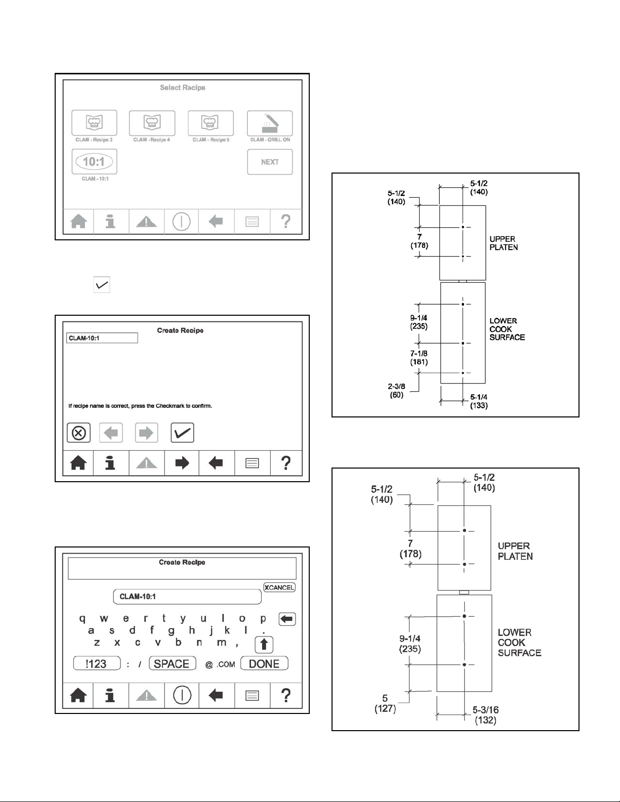
Figure-79 identifies the probe locations for the Model
C850, C852, and C858 grill.
key
the menu item under Create Recipe. See Figure-77.
16. Type the name of your new recipe. (The Back Arrow
key is used as a backspace key.) Select DONE when
complete. See
to confirm. If the name is not correct, press
Figure-77
Figure-78.
Figure-79
Figure 80 identifies the probe locations for the Model
C854, C856, and C860 grill.
Figure-78
Figure-80
45
Page 46

Surface Temperature Calibration
Patty Placement
Important! Make sure the grill has been turned on and
allowed to reach set point. (approx. 45 min.)
1. Make sure all surfaces are clean of carbon.
2. Probe calibration should be performed with the upper
release sheets installed.
3. Use the restaurant’s surface probe.
4. Select the Temperature key (top left second
key) on the main screen.
5. Press and hold for 3 seconds.
6. Place the surface probe on the desired zone to be
calibrated. Refer to Probe Calibration on
7. Using the up/down arrow keys, adjust the
temperatures to match the surface probe
temperatures.
8. Press the Checkmark Key to save the
adjustments.
page 45.
Adjust Cook Times
1. Select the menu item to have the cook time adjusted.
Select the menu item key it will be highlighted in blue.
2. Select the Cook Time key located on the top left
of the main screen.
3. Press and hold for 3 seconds.
4. Using the up/down arrow key adjust the cook time
needed.
5. Press the Checkmark Key to save the
adjustments.
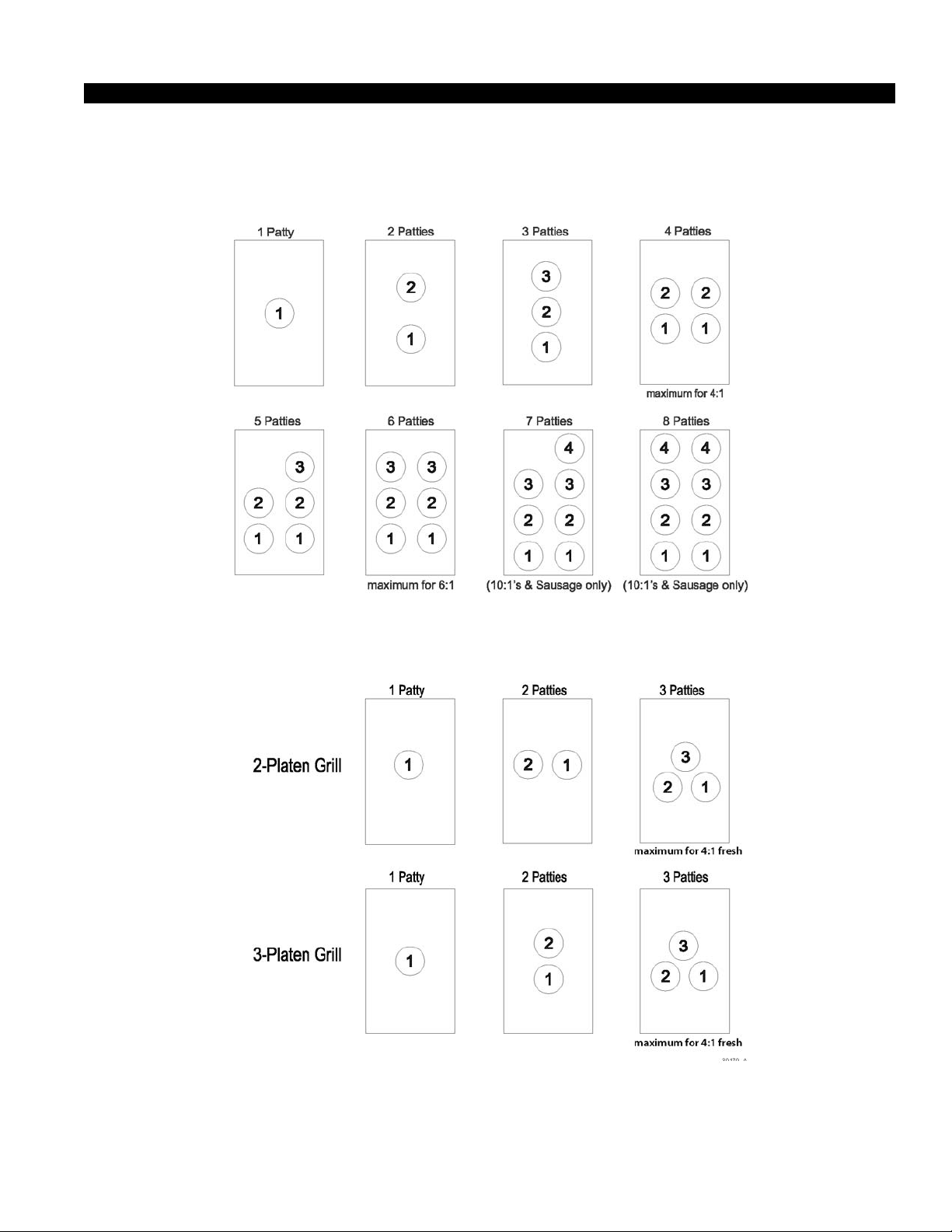
Placement procedures of meat products must be
followed on the grill. Meat must be placed on the lower
grill platen, two patties at a time, from front to back, per
the patty placement guide on page 47. When the cook
cycle is complete, the upper platen will rise.
The patties must be removed immediately after the upper
platen has been raised to the OPEN position and the
meat has been seasoned. Remove the patties, one at a
time, from front to back and right to left, per the patty
placement guide on page 47.
The maximum amount of meat patties to be cooked on
each heat zone is as follows:
• 8 regular (10:1) patties
• 6 (6:1) patties
• 4 quarter-pound (4:1) patties
• 8 sausage patties
• 6 circular bacon
The U.S. Recipe list includes:
• CLAM 10:1
• CLAM 6:1
• CLAM 4:1
• CLAM-GRILL CHKN
• CLAM-FRESH 4:1
• CLAM-SAUSAGE FZN
• CLAM-MCRIB
• CLAM-STEAK
• FLAT-GRILL CHKN
• FLAT-FOLDED EGG
• FLAT-ROUND EGG
• FLAT-10:1
• FLAT-4:1
• FLAT-MCRIB
• FLAT-SAUSAGE FZ
• FLAT-HOT CAKES
• CLAM-MUSHROOMS
• CLAM-ROAST BACON
• CLAM-FOLDED EGGS
• CLAM-ROUND EGGS
• CLAM-LOR ONION
• LIFECYCLE
The following chart is to be used as the patty placement
guide.
46
Page 47
SAUSAGE, CIRCULAR BACON AND PATTY PLACEMENT GUIDE
30170_A
Models C850, C852, C854, C856, C858, C860 Next Generation Grill 10:1, 6:1, 4:1
Laying Pattern
Note: Lay the patties on the grill two at a time from front to back.
Fresh Product Patty Placement Guide
Figure-81
Figure-82
47
Page 48

Pulling Pattern
Note: Remove the patties one at a time in the order shown from front to back and right to left.
Figure-83
Note: Patty placement procedures for international markets may differ. Follow the recommendations of your local
McDonald's authorities.
48
Page 49

STANDBY PROCEDURES
30148_A
30149_A
Whenever the grill is idle and product is not being
cooked, the upper platen must be placed in the Standby
position.
1. To place the upper platen in the Standby position,
press the STANDBY button twice from the Open
position. See
2. To raise the upper platen to the Open position to
resume cooking, press the RAISE button.
See Figure-85.
Figure-84.
Figure-84
CLEANING AFTER EACH RUN OF PRODUCT
(USING LOWER RELEASE SHEETS)
Note: This manual contains separate procedures for
grills that use lower release sheets and for grills that do
not use lower release sheets. Use the appropriate
procedures for your grill.
If your grill does not use lower release sheets, go to
page 50.
Note: Do not use excessive pressure when wiping the
release sheet with the squeegee. Using excessive
pressure can scratch or tear the release sheet.
1. Squeegee the lower release sheet from front to back.
See
Figure-86.
Figure-85
Note: If the grill remains idle for 5 continuous minutes
without being placed in Standby, a tone will sound and
the display will flash PUT GRILL IN STANDBY.
Note: FRANCE ONLY: With the upper platen in the
OPEN position, press the STANDBY button to enter the
Standby. To start cooking, lower the upper platen.
CAUTION! Never use force to raise the upper
platen. Damage to components may result. Only use the
RAISE button to open the upper platen.
Figure-86
2. Squeegee the upper release sheet from top to
bottom.
See Figure-87.
Figure-87
49
Page 50

3. Push the residue into the grease trough.
30150_A
30151_A
Figure-88
4. Carefully sque egee the air bubbles from the center to
the side, making sure the release sheet does not
become folded or creased.
6. Wipe the top platens and grill surface four times an
hour with a sanitizer-soaked grill cloth.
Figure-91
7. As needed during operation, use a sanitizer-soaked
grill cloth to clean the rear grease shield and the
bullnose areas.
See Figure-92.
Figure-89
5. Wipe the squeegee with a sanitizer-soaked grill cloth.
Figure-90
Figure-92
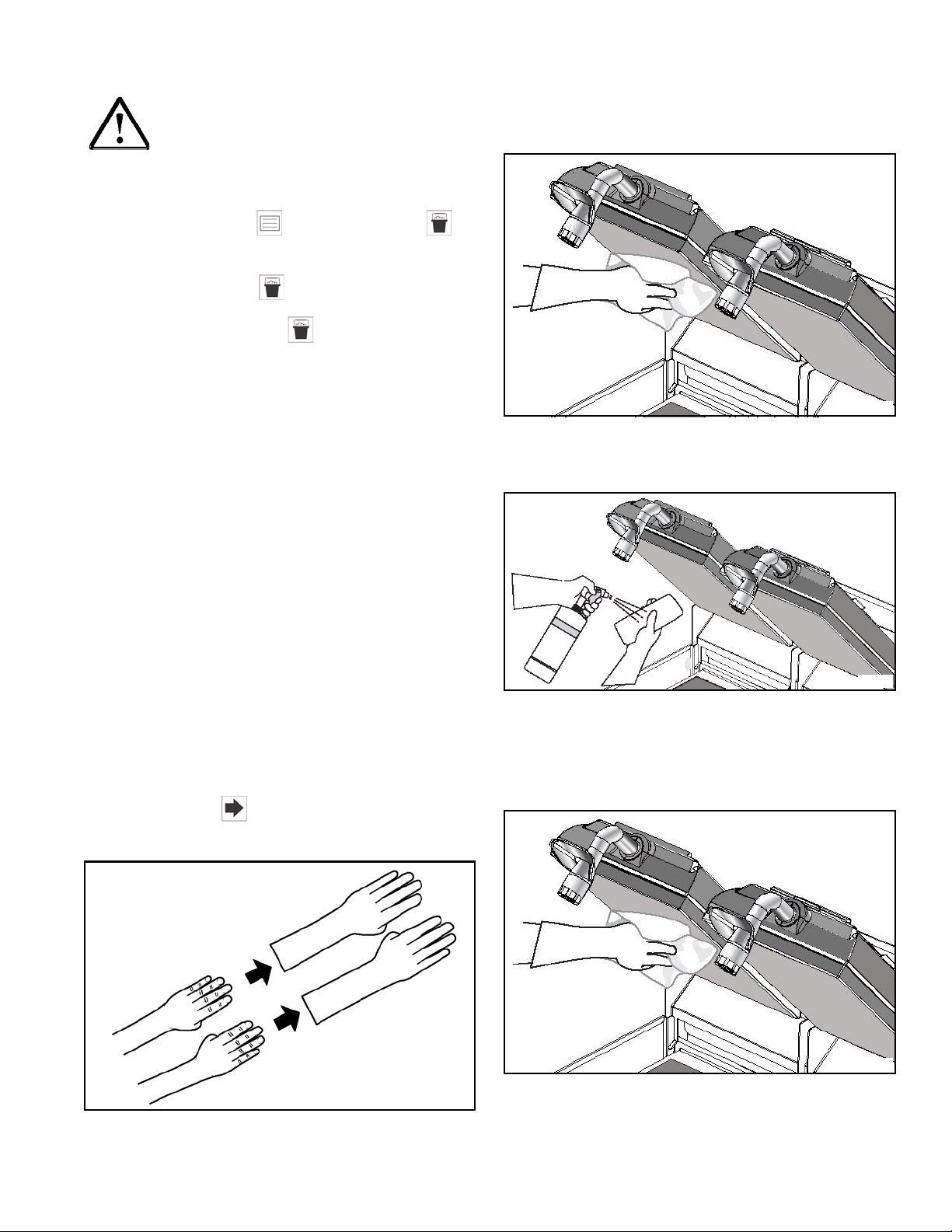
CAUTION! The upper platen surface and
release sheet are very hot. To prevent burn injuries, wear
heat-resistant gloves when replacing the release sheets.
CLEANING AFTER EACH RUN OF PRODUCT
(NOT USING LOWER RELEASE SHEETS)
Note: This manual contains separate procedures for
grills that use lower release sheets and for grills that do
not use lower release sheets. Use the appropriate
procedures for your grill.
If your grill uses lower release sheets, go to page 49.
50
Page 51

1. Using the grill scraper, scrape the grease on the
30149_A
lower grill plate from front to back. Do not scrape
across the rear of the lower grill plate with the grill
scraper. See
Figure-93.
3. Using the wiper squeegee, push the grease at the
rear of the lower grill plate into the grease can.
Do not use the grill scraper for this step.
See Figure-95.
Figure-93
2. Use the wiper squeegee to clean the release sheet
on the upper platen. Use a diagonal motion to clean
the sheet. Hold the handle at a slightly upward angle,
with the wiper end facing downward.
See Figure-94.
Figure-94
Note: Do not use excessive pressure when wiping the
release sheet with the squeegee. Using excessive
pressure can scratch or tear the release sheet.
Figure-95
4. Use the grill cloth to clean the rear grease shield and
the bullnose areas as needed during operation.
Note: To increase the life of the release sheet, wipe it
with a damp, folded grill cloth a minimum of four times
every hour.
Display the Current Status
Note: The actual temperatures may be displayed at any
time, including during a Cook cycle.
Press the Information key . The following
information will be displayed:
• The current grill temperatures for the upper and
lower plates.
• The ambient temperature of the control board.
• The Clean key displays the time since the
grill was last cleaned and the length of time it
took to clean the grill.
• The Auto Calibrate key indicates if the grill
is calibrated and the current menu item.
51
Page 52

Wipe Down Mode
1. Press the Wipe Down key to enter the Wipe Down
mode. See
Figure-96.
4. Remove the upper and lower release sheets from the
grill.
See Figure-99.
Figure-99
Figure-96
2. The following screen will allow you to move the
platen up and down.
3. Press The Full Clean key . See Figure-98.
See Figure-97.
Figure-97
DAILY CLEANING PROCEDURES (USING
LOWER RELEASE SHEETS)
Note: This manual contains separate procedures for
grills that use lower release sheets and for grills that do
not use lower release sheets. Use the appropriate
procedures for your grill.
If your grill does not use lower release sheets, go to
page
60.
CAUTION! Never use cold water or ice to cool
the upper platen or the lower grill plate. Failure to comply
may result in machine damage.
• Never use grill screens on the upper platen or the
lower grill plate.
• Never allow the grill scraper or abrasive cleaning
materials to come in contact with the release sheet.
1. Raise the up per platen to the Open position by
pressing the red RAISE button. See
Figure-100.
Figure-98
Figure-100
52
Page 53
CAUTION! Never use force to raise the upper
30150_A
30152_A
30150_A
platen. Damage to components may result. Only use the
RAISE button to open the upper platen.
2. Press the Menu key until the Clean key is
displayed.
3. Press the Clean key .
4. Press the Full Clean key .
5. Gather the necessary cleaning supplies while the grill
is cooling down:
•Kay® grill cleaning pad holder
®
•Kay
•Kay
grill cleaning pad
®
Hi-temp tool w/flat paddle attachment
• Flat paddle multi-use tool pad
• Flat paddle universal pad
®
•Kay
QSR heat-activated grill and toaster
cleaner (HAGTC)
• Heat-resistant gloves (14 inches in length)
•Kay
®
Hi-temp tool with double-sided bristle
brush
• Squeegee
• Sundae spoon
• Release sheet storage tray
• Soy adhesion flakes
When the cook surfaces reach the proper temperature
for cleaning, Cleaning in progress will be displayed.
6. Press the Next key to proceed.
8. Use the sanitizer-soaked grill cloth to clean the
exposed surfaces of the upper and lower release
sheets.
See Figure-102.
Figure-102
9. Spray a clean, sanitizer-soaked grill cloth with one
spray of grill cleaner.
See Figure-103.
Figure-103
10. Us e the sanitizer-soaked grill cloth to wipe clean the
exposed surfaces of the upper release sheets,
including the sides. Repeat the cleaning for the lower
release sheets.
See Figure-104.
7. Put on heat-resistant gloves. See Figure-101.
Figure-101
Figure-104
53
Page 54

11. Rinse the upper and lower release sheets with a
30150_A
separate sanitizer-soaked grill cloth. Wipe until the
grill cleaner residue has been fully removed. See
Figure-105.
Figure-105
12. Remove the release sheet locking clips and the
upper and lower release sheets. Wash and rinse the
clips in the three-compartment sink. If necessary,
soak them in a hot solution of SolidSense APSC to
remove carbon accumulation.
See Figure-106.
Figure-107
14. Spray a clean, sanitizer-soaked grill cloth once with
grill cleaner. Wipe the soiled side of the release sheet
until clean.
See Figure-108.
Figure-106
13. Place all release sheets flat on the release sheet
storage tray, clean side down. Do not fold, crease, or
place them on sharp objects. Do not clean the
release sheets in the three-compartme nt sink.
See
Figure-107.
Figure-108
15. Rinse with a se parate clean, sanitizer-soaked grill
cloth to rinse off the remaining grill cleaner. Repeat
for all of the release sheets.
See Figure-109.
Figure-109
16. Spray the upper platens with grill cleaner, starting
with the sides and back. If you have three upper
platens, lower the middle platen first to easily access
the adjoining sides of the right and left platens.
17. After spraying the sides, spray the surface of each
upper platen three times to cover the bottom, middle,
and top.
See Figure-110.
54
Page 55

Figure-110
30153_A
30154_A
30155_A
30156_A
Figure-113
18. Firmly attach the cleaning pad to the Kay® grill
cleaning pad holder.
Figure-111
19. Using the Kay® grill cleaning pad holder, distribute
the grill cleaner around the upper platens to ensure
full coverage.
See Figure-112.
21. Beginning on the left lower plate, pour the dosed
1/2 oz. of grill cleaner from left to right in the shape of
an arched M. Repeat for each lower plate until all of
them are fully covered.
See Figure-114.
Figure-114
22. Spread the grill cleaner thoroughly on the lower
surface to ensure full coverage.
See Figure-115.
Figure-112
20. Remove the cap from the dosing bottle and squeeze
the bottle to fill the dosing cup to 1/2 oz. as marked.
See Figure-113.
Figure-115
55
Page 56

23. Scrub the upper and lower platen with the grill
30154_A
30157_A
30158_A
cleaning pad and holder.
See Figure-116.
26. Pull out the grill. See Figure-119.
Figure-119
Figure-116
24. If needed, scrub the upper platen with the Kay®
double-sided grill brush.
See Figure-117.
Figure-117
25. Using a sanitizer-soaked grill cloth, wipe the lower
plate.
See Figure-118.
27. To clean the lower plate sides, raise the lower platen.
See Figure-120.
Figure-120
28. Once the platen has raised, put the multi-use tool
pad on the multi-use tool. Spray the multi-use tool
pad with grill cleaner.
See Figure-121.
Figure-118
Figure-121
29. Scrub the lower platen sides. Repeat until the sides
are fully covered.
56
See Figure-122.
Page 57

Figure-122
30159_A
30. Remove and empty the grease cans and take them
to the three-compartment sink. Leave them at the
sink until the grill cleaning is finished.
See Figure-123.
32. Wipe the outer edges of the lower plate.
See Figure-125.
Figure-125
33. Continue cleaning through the Clean mode until the
lower plate rises.
34. Once the lower plate is raised, spray the multi-use
tool pad with grill cleaner and repeat until the sides
are fully covered.
See Figure-126.
Figure-123
31. Remove the rear grease guard and take it to the
three-compartment sink to wash, rinse, and sanitize.
See Figure-124.
Figure-124
Figure-126
35. Remove the multi-use tool pad from the flat paddle
tool and snap on the sanitizer-soaked universal pad.
Clean in between and behind the platens and
surrounding areas, such as the hood and bullnose.
See Figure-127.
57
Page 58
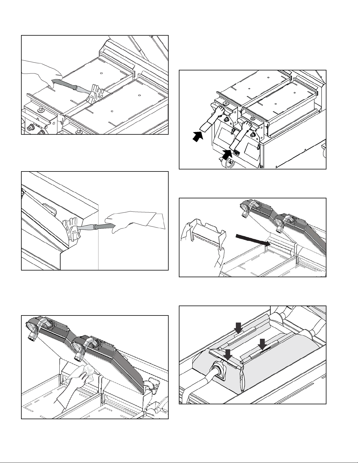
Figure-127
30161_A
30160_A
36. With the grill pulled out, wipe down the front and back
areas of the grill with the universal pad.
See Figure-128.
38. Remember to use a clean side of the cloth with each
wiping. Discard the grill cloth in the soiled towel pail.
39. Once the clean mode is completed. Push the grill
back into place.
Figure-130
40. Reinstall the rear grease guard after it has been
washed and rinsed.
See Figure-131.
Figure-128
37. Rinse the upper platens and lower plates with a
clean, sanitizer-soaked grill cloth. Also rinse the
surrounding areas such as the hood, bull nose, and
backsplash.
See Figure-129.
Figure-129
Figure-131
41. Reinstall the upper release sheets prior to use.
See Figure-132.
Figure-132
58
Page 59

Note: Reverse the cooking side of the release sheets on
30147_A
30149_A
a daily basis (example: black side on odd days; gray or
brown side on even days).
42. Using a sundae spoon, distribute two level spoonfuls
of soy adhesion flakes over a warm 3 ft. (1 m) lower
grill surface, allowing the flakes to melt. Spread on
the cooking zone with a clean squeegee.
See Figure-133.
Figure-133
Figure-135
45. Place the fan interlock switch in the OFF position if
the restaurant is closing; otherwise, return it to the
appropriate setting for cooking.
See Figure-136.
43. Install the lower release sheets. See Figure-134.
Figure-134
44. Squeegee the air bubbles and wrinkles out of each
release sheet.
See Figure-135.
Figure-136
46. Wash, rinse, and sanitize the rear grease guard and
grease cans at the three-compartment sink. Reinstall
the grease cans.
See Figure-137.
Figure-137
59
Page 60

47. Bring the cleaning tools to the three-compartment
sink. Rinse or launder the mop sock; then place it in a
clean, sanitizer pail. Once the grill pad and multi-use
tool pad have cooled, take them to wash and rinse at
the three-compartment sink. Allow to air-dry.
48. Flip the grill pad over and reinstall on the tool for the
next grill cleaning.
If your grill uses lower release sheets, go to page 52.
CAUTION! Never use cold water or ice to cool
the upper platen or the lower grill plate. Failure to comply
may result in machine damage.
49. Wash, rinse, and sanitize all of the utensils and tools
used to clean the grill at the three-compartment sink.
See Figure-138.
Figure-138
Note: Reverse the cooking side of the release sheets on
a daily basis (example: black side on odd days; gray or
brown side on even days).
50. Leave the upper platens in the Open position
overnight.
CLEANING PROCEDURE-24 HOUR STORES
(WITH LOWER RELEASE SHEETS)
• Never use grill screens on the upper platen or the
lower grill plate.
• Never allow the grill scraper or abrasive cleaning
materials to come in contact with the release sheet.
1. Raise the up per platen to the Open position by
pressing the red RAISE button. See
Figure-139.
Figure-139
CAUTION! Never use force to raise the upper
platen. Damage to components may result. Only use the
RAISE button to open the upper platen.
1. Clean the grill using the daily cleaning procedures on
pages
52–60.
2. After the grill pad has cooled, remove, wash, and
rinse it thoroughly at the three-compartment sink.
Turn the grill pad over and reinstall it on the grill pad
holder.
3. Wash, rinse, and sanitize all utensils and tools used
to clean the grill at the three-compartment sink.
4. The grill is now ready to use.
DAILY CLEANING PROCEDURES (WITHOUT
LOWER RELEASE SHEETS)
Note: This manual contains separate procedures for
grills that use lower release sheets and for grills that do
not use lower release sheets. Use the procedures
appropriate for your grill.
2. Press the Men u key until the Clean key is
displayed.
3. Press th e Clean key .
4. Press the Full Clean key .
5. Gather the necessary cleaning supplies while the grill
is cooling down:
• Kay® grill cleaning pad holder
®
• Kay
• Kay
grill cleaning pad
®
Hi-temp tool w/flat paddle attachment
• Flat paddle multi-use tool
• Flat paddle universal pad
®
• Kay
QSR heat-activated grill and toaster cleaner
(HAGTC)
• Heat-resistant gloves (14 in. length)
60
Page 61

• Kay® Hi-temp tool with double-sided bristle brush
30150_A
30152_A
30150_A
30150_A
• Squeegee
• Sundae spoon
• Release sheet storage tray
• Soy adhesion flakes
When the cook surfaces reach the proper temperature
for cleaning, Cleaning in progress will be displayed.
6. Press the Next key to proceed.
7. Put on heat-resistant gloves. See Figure 140.
9. Spray a clean, sanitizer-soaked grill cloth with one
spray of grill cleaner.
See Figure-142.
Figure-142
10. Us e the sanitizer-soaked grill cloth to wipe clean the
exposed surfaces of the upper release sheets,
including the sides. Repeat the cleaning for the lower
release sheets.
See Figure-143.
Figure-140
CAUTION! The upper platen surface and
release sheet are very hot. To prevent burn injuries, wear
heat-resistant gloves when replacing the release sheets.
8. Wipe the exposed surface of the release sheets with
a clean, sanitizer-soaked grill cloth.
See Figure-141.
Figure-143
11. Rinse the upper release sheets with a separate
sanitizer-soaked grill cloth. Wipe until the grill cleaner
residue has been fully removed.
See Figure-144.
Figure-141
Figure-144
61
Page 62

12. Remove the release sheet locking clips and the
30163_A
30164_A30164_A30164_A
upper release sheets. Wash and rinse the clips in the
three-compartment sink. If necessary, soak them in a
hot solution of SolidSense APSC to remove carbon
accumulation.
See Figure-145.
Figure-145
13. Place all of the release sheets clean side down flat
on the release sheet storage tray.
See Figure-146.
15. Rinse with a se parate clean, sanitizer-soaked grill
cloth to rinse off the remaining grill cleaner. Repeat
for all of the release sheets.
See Figure-148.
Figure-148
16. Remove the rear grease guard and take it to the
three-compartment sink to wash, rinse, and sanitize.
See Figure-149.
Figure-146
14. Spray a clean, sanitizer-soaked grill cloth once with
grill cleaner. Wipe the soiled side of the release sheet
until clean.
See Figure-147.
Figure-147
Figure-149
17. Spray the upper platens with grill cleaner, starting
with the sides and back. If you have three upper
platens, lower the middle platen first to easily access
the adjoining sides of the right and left platens.
18. After spraying the sides, spray the surface of each
upper platen three times to cover the bottom, middle,
and top.
62
See Figure-150.
Page 63

Figure-150
30153_A
30154_A
30155_A
19. Firmly attach the cleaning pad to the Kay® grill
cleaning pad holder.
NOTICE! DO NOT use metal scrapers,
abrasive pads, screens, or wire brushes. Damage to
components may result.
22. Remove the cap from the dosing bottle an d sq ue ez e
the bottle to fill the dosing cup as marked 1/2 oz.
See Figure-152.
Figure-152
23. Beginning on the left lower plate, pour the dosed
1/2 oz. of grill cleaner from left to right in the shape of
an arch pattern M. Repeat for each lower plate until
all of them are fully covered.
See Figure-153.
20. Apply the grill cleaner to the platen surfaces, starting
from the right platen to the left platen.
21. Using the Kay® grill cleaning pad holder, distribute
the grill cleaner around the upper platens to ensure
full coverage.
See Figure-151.
Figure-151
Figure-153
24. Apply the grill cleaner to the back side of the platens,
from the right platen to the left platen.
25. Spread the grill cleaner thoroughly on the lower
surface to ensure full coverage.
See Figure-154.
63
Page 64

Figure-154
30156_A
30154_A
30157_A
30159_A
26. Scrub the upper and lower plate with the grill
cleaning tool and pad.
See Figure-155.
Figure-155
27. If needed, scrub the upper platen with the Kay®
double-sided grill brush.
See Figure-156.
Figure-157
Note: Allowing the grill cleaner to sit on the grill surfaces
will require less effort and time to scrub heavy soil
buildup and achieve a clean grill.
29. To clean the lower plate sides , pull out the grill and
raise the lower plates.
See Figure-158.
Figure-158
30. Once the platen has raised, put the multi-use tool
pad on the flat paddle tool. Spray the multi-use tool
pad with grill cleaner.
See Figure-159.
Figure-156
28. Remove and empty the grease cans and take them
to the three-compartment sink. Leave them at the
sink until the grill cleaning is finished. Continue
through the clean mode until the lower plate rises.
See Figure-157.
Figure-159
31. Scrub the lower plate sides. Repeat until the sides
are fully covered.
64
See Figure-160.
Page 65

Figure-160
30159_A
30161_A
32. Remove the multi-use tool pad from the flat paddle
tool and snap on the sanitizer-soaked universal pad.
Clean in between and behind the platens and
surrounding areas, such as the hood and bullnose.
See Figure-161.
34. Rinse the upper platens and lower plates with a
clean, sanitizer-soaked grill cloth. Also rinse the
surrounding areas, such as the hood, bull nose, and
rear grease guard.
See Figure-163.
Figure-163
35. Remember to use a clean side of the cloth with each
wiping. Discard the grill cloth in the soiled towel pail.
36. Push the grill back into place. See Figure-164.
Figure-161
33. With the grill pulled out, wipe down the front and back
areas of the grill with the universal pad.
See Figure-162.
Figure-162
Figure-164
37. Reinstall the upper release sheets prior to use.
See Figure-165.
Figure-165
65
Page 66

Note: Reverse the cooking side of the release sheets on
30160_A
a daily basis (example: black side on odd days; gray or
brown side on even days).
38. Wash and rinse the grease pans in the threecompartment sink.
See Figure-166.
41. Bring the cleaning tools to the three-compartment
sink. Rinse or launder the universal pad; then place it
in a clean sanitizer pail. Once the grill pad and
multi-use tool pad have cooled, take them to wash
and rinse at the three-compartment sink. Allow them
to air-dry.
Figure-166
39. Reinstall the grease pans. See Figure-167.
Figure-167
40. Reinstall the rear grease guard. See Figure-168.
Figure-169
42. Flip the grill pad over and reinstall it on the tool for the
next grill cleaning.
43. Wipe the remaining grill surfaces with a clean,
sanitizer-soaked grill cloth.
Figure-170
44. Apply a light coat of fryer cooking oil to the entire
lower grill surface.
Figure-168
45. Leave the upper platens in the Open position
overnight.
46. After the grill pad has cooled, remove it from the pad
holder and wash and rinse it thoroughly at the
three-compartment sink. Turn the grill pad over and
reinstall it on the grill pad holder.
66
Page 67

CLEANING PROCEDURE-24 HOUR STORES
(WITHOUT LOWER RELEASE SHEETS)
1. Clean the grill using the daily cleaning procedures on
pages
2. After the grill pad has cooled, remove, wash, and
rinse it thoroughly at the three-compartment sink.
Turn the grill pad over and reinstall it on the grill pad
holder.
3. Wash, rinse, and sanitize all utensils and tools used
to clean the grill at the three-compartment sink.
60–66.
Figure-172
3. The Recovery mode is on. See Figure-173.
Figure-171
4. The grill is now ready to use.
QUARTERLY RECOVERY MODE PROCEDURES
(Follow the McD Grill Recovery Cleaning Procedure
from EcoLab)
Note: Use new and clean tools for recovery application.
Note: PPE (gloves, apron, and a face shield) should be
worn when following the cleaning procedure due to the
high temperature of the grill.
Important! : Remove the upper and lower release sheets
prior to Recovery procedure.
CAUTION! Do not remove the grill filters.
Cleaning without the filters can cause severe burns or
fire.
1. Ensure Recover y mode programming has been
completed on the grill before initiating cleaning.
2. Press the Recovery key to enter the Recovery
mode. See Figure-172.
Figure-173
4. Press the STANDBY button to start the recovery
process. See
5. Select the Recovery setting from the grill
interface and allow the grill to cool before cleaning.
Do not turn the fan interlock off. Allow the grill to
reach 285F before cleaning. A temperature of 285F
is critical to maximize the effectiveness of the
cleaning product.
Figure-174.
Figure-174
67
Page 68

6. Put on heat-resistant gloves. See Figure-175.
Figure-175
9. Clean the release sheets (see O&T Manual or Grill
Cleaning Kay Card for details. See
Figure-178.
7. Remove and empty the grease cans, then rinse and
reinstall. See
Figure-176.
Figure-176
8. Remove all of the clips, bars, and release sheets
before the recovery cleaning. See
Figure-177.
Figure-178
10. Take the clips and bars to the three-compartment
sink; then wash, rinse, and sanitize them.
11. G ather the materials for cleaning while the grill is
cooling down.
12. When the grill has reached 285 F, it is ready for
cleaning.
13. Put Personal Protective Equipment on (examples:
gloves, face shield, and apron). See
Figure-179.
Figure-177
Figure-179
14. Wipe the upper platens and lower plates with a clean,
sanitizer-soaked grill cloth before cleaning. Discard
the cloth in the soiled towel pail after use.
See Figure-180.
68
Page 69

Figure-180
30150_A
30154_A
30169_A
30156_A
15. Scrape off as much carbon buildup as possible from
all surfaces of the upper platens (especially the back
and corners) with the scraper.
16. With all of the platens up, apply sufficient Kay® QSR
heat activated grill & toaster cleaner to the grill tool
pad and coat the edges of the upper platens with the
product. See
Figure-181.
Figure-181
Note: If needed, pull the grill out from the wall and stand
to the side of the grill to reach the back side of the upper
platens. Pour additional Kay
toaster cleaner onto a grill cloth and apply it to hard
®
QSR heat activated grill &
to-reach areas. See Figure-182.
Figure-182
17. Use a separate bottle of Kay® QSR heat-activated
grill & toaster cleaner and remove the cap. Evenly
pour the entire bottle of cleaner onto the lower plate
surface of the grill along with the remainder of the
first bottle.
See Figure-183.
Figure-183
Note: Make sure to coat the entire surface of the lower
®
plate. Use the Kay
grill cleaning pad holder with the pad
if needed to spread product for full coverage of the grill
surface. See
Figure-184.
Figure-184
69
Page 70

18. Lower both of the upper platens onto the lower plate
30157_A
30156_A
®
surface coated with Kay
QSR heat-activated grill &
toaster cleaner.
19. Allow the upper and lower plates to soak for a full
cycle-approximately 17 minutes.
20. After the cycle is completed and the upper platens
have risen, scrub the flat surface, edges, a nd sides of
the upper platens with the Kay
brush. Scrub until the soil liquefies. See
®
double sided grill
Figure-185.
Figure-185
Note: In order to scrub all of the edges of the upper
platens, one upper platen will need to be lowered to
reach the inside edge of both platens with the brush.
24. Squeegee the grill cleaner into the grease cans.
See Figure-187.
Figure-187
25. Thoroughly rinse both the upper and lower plates
with clean, sanitizer-soaked grill cloths. Repeat until
no residual Kay
®
QSR heat-activated grill & toaster
cleaner remains. Clean the surrounding areas such
as the hood, bullnose, and backsplash with clean,
sanitizer-soaked grill cloths. Discard the cloths into
the soiled towel pail after use. See
Figure-188.
21. Make sure to have both upper platens raised before
cleaning the lower plate.
22. Scrape off carbon buildup off of all surfaces of the
upper platens (especially the back and corners) with
the scraper.
23. Scrub the lower cook surface and all areas using the
®
grill cleaning pad holder with the pad.
Kay
See Figure-186.
Figure-186
Figure-188
Note: In order to scrub all of the edges of the upper
platens, one upper platen will need to be lowered to be
able to reach the inside edge of both platens with the
brush.
26. If carbon buildup remains, repeat step 13 through
step 25.
70
Page 71
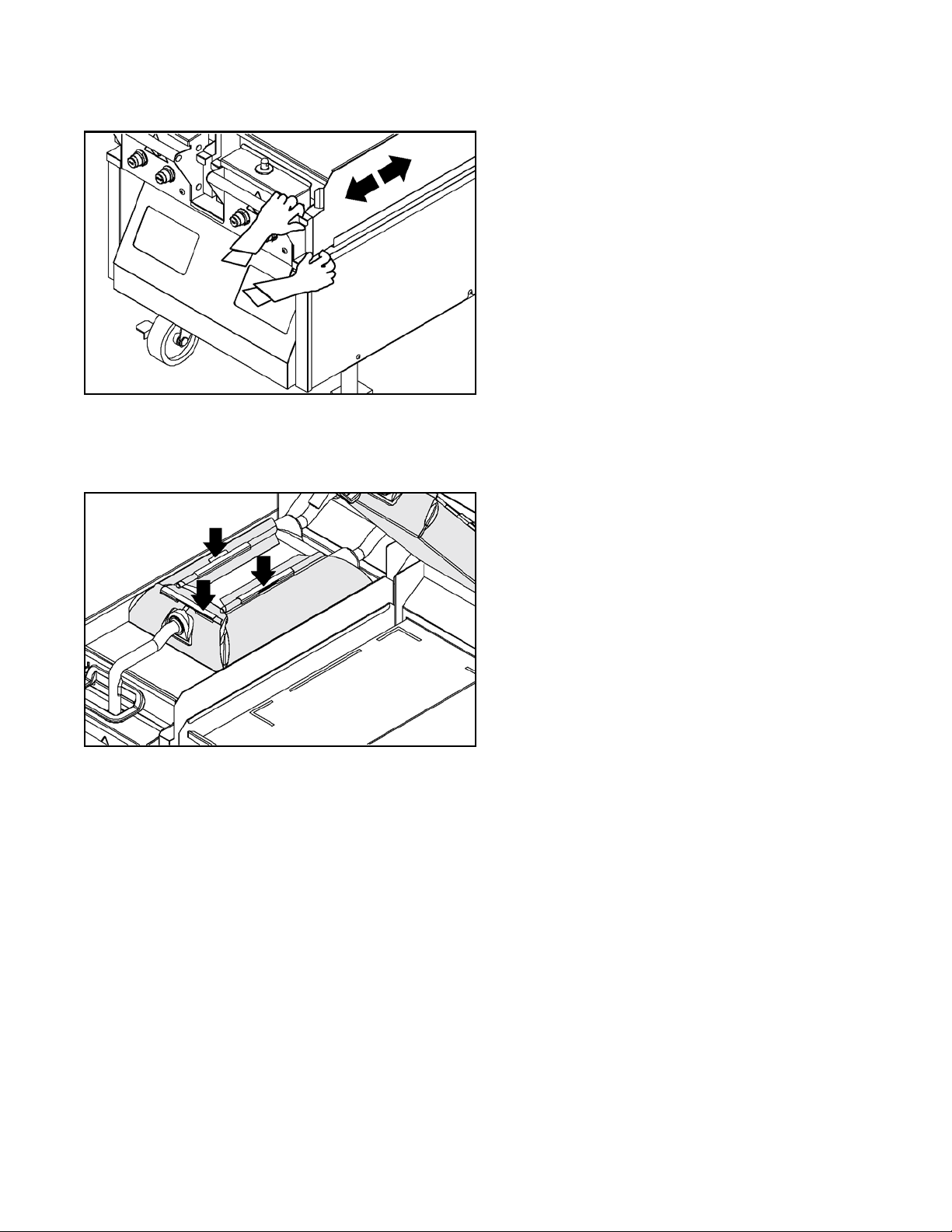
27. Remove and empty the grease trough. Rinse and
replace it. See
Figure-189.
Figure-189
28. Reinstall the upper and lower release sheets (see
O&T Manual or Grill Cleaning Kay Card for details).
See
Figure-190.
Figure-190
29. Once the grill pad has cooled, remove; wash and
rinse it thoroughly at the three-compartment sink. Flip
the grill pad over and reinstall it on the tool for the
next grill cleaning.
30. Wash, rinse, and sanitize all of the utensils and tools
used to clean the grill at the three-compartment sink.
71
Page 72

Notes:
72
Page 73

TROUBLESHOOTING GUIDE
DANGER! Improper installation, adjustment,
alteration, service, or maintenance can cause property
damage, injury, or death. Read the installation, operating,
and maintenance instructions thoroughly before installing
or servicing this machine.
IMPORTANT! Inspection, testing, and repair of
electrical equipment should be performed only by
qualified service personnel.
WARNING! The machine should be
disconnected from all electricity when servicing, except
when electrical tests are required. Failure to comply may
result in severe personal injury or equipment damage.
DANGER! Use extreme care during electrical
circuit tests. Live circuitry may be exposed. Failure to
follow this instruction may result in severe injury or death.
CAUTION! The machine must be pulled away
from the wall for thorough cleaning. When returning the
machine to its original position, use extreme caution to
smoothly and slowly roll the machine back into place.
Failure to do so may cause the machine to tip, and will
cause severe equipment damage or personal injury.
73
Page 74

Entire Grill (All Models)
Problem Probable Cause Remedy
EQUIPMENT TROUBLESHOOTING
The exhaust hood alone does not turn
on when the fan interlock switch is in the
ON position.
The grill alone will not turn on when the
fan interlock switch is in the ON position.
The platen will not stay down when the
STANDBY button is pressed.
The grill displays TOO COOL. The grill is not within the specified
The fan interlock switch is faulty. Call for service.
Loose or broken wires to switch. Call for service.
The grill breaker has tripped. Reset the breaker.
The grill's control voltage cord has
become unplugged.
The Ansul reset tripped. Press the Ansul reset button.
Internal component failure. If the problem still remains, call for
The cavity where the handle latches to
the latch solenoid (located at the front of
the grill) is dirty.
Internal component failure. If the problem still remains, call for
temperature range of the specified
recipe.
Reseat the power cord.
service.
Clean the handle foot and/or the latch
solenoid post.
service.
Wait for the grill to reach temperature
range for specified recipe.
Three-phase breaker tripped. Reset the breaker.
Three-phase cord has become
unplugged from the wall.
The grill displays TOO HOT. The grill is not within the specified
temperature range of the specified
recipe.
Thermocouple X is open. Internal component failure. Call for service.
Thermocouple X is shorted. Three-ph ase cord has become
unplugged from the wall.
Internal component failure. If the problem still remains, call for
The grill is making loud whistling noise
when cooking product with egg ring.
The egg ring is dirty and causing steam
to escape.
Reseat the three-phase plug.
Wait for the grill to reach temperature
range for specified recipe.
Reseat the three-phase plug.
service.
Clean the egg ring.
74
Page 75

PRODUCT TROUBLESHOOTING
Problem Probable Cause Remedy
The product is undercooked or
overcooked.
The product is not cooking evenly. The upper platen or lower cook surface
Eggs are pooling to one side of the egg
ring.
The release material is dirty or worn. Clean and/or replace the release sheets.
The upper platen or lower cook surface
is not clean or has carbon buildup.
Incorrect cook time. Increase or decrease the cook time
The grill's gaps are not within
specification.
are not clean or have carbon buildup.
The release sheet material is dirty or
worn.
The grill's gaps are not within
specification.
The grill has become unlevel. Level the grill.
The grill's gaps are not within
specification.
Cleaning procedures must be followed
to properly clean the grill and remove
carbon buildup.
accordingly. See the Cook Time key on
page 33.
Refer to the gapping procedure in the
service manual.
Cleaning procedures must be followed
to properly clean the grill and remove
carbon buildup.
Clean and/or replace the release sheets.
Refer to the gapping procedure in the
service manual.
Refer to the gapping procedure in the
service manual.
The grill displays Lower Plate Stall, and
platen comes up.
The product is not recognized. Carbon buildup on the upper and/or
The product being cooked is misshaped
or out of specification.
The wrong recipe was selected to cook. Review and select the correct recipe
lower cook surfaces is interfering with
the Auto Gap settings.
The grill plate has become uneven. Ref er to the gapping procedure in the
The wrong product is being used. Ensure correct product and settings.
The grill is not set in the Auto Product
Recognition mode.
Press the STANDBY button again. The
product will flatten as it thaws.
item. Restart the Cook cycle.
Remove the carbon and clean the upper
and lower cook surfaces.
service manual.
Ensure the grill control is set to Auto
Product Recognition mode.
75
Page 76

LIMITED WARRANTY ON EQUIPMENT
TAYLOR COMPANY LIMITED WARRANTY ON C850 SERIES GRILL EQUIPMENT FOR MC DONALDS
Taylor Company is pleased to provide this limited warranty on new Taylor-branded C850 Series grill equipment
available from Taylor (the Product) to the original McDonalds purchaser only.
LIMITED WARRANTY
Taylor warrants the Product against failure due to defect in mater ials or workman ship under nor mal use and service as
follows. All warranty periods begin on the date of original Product installation. If a part fails due to defect during the
applicable warranty period, Taylor, through an authorized Taylor distributor or service agency, will provide a new or
remanufactured part, at Taylors option, to replace the failed defective part at no charge for the part.
Product Part Limited Warranty Period
Taylor C850 Series Grills Parts not excluded below Two (2) years
In addition, during the two (2) year period commencing on the date of original installation of the Product, Taylor will also
provide, through an authorized Taylo r dist rib ut or or service agency, all service needed to replace the failed defective
part at no charge for the service. This no-charge service shall not be available for service performed by authorized
McDonalds service technicians. Local sales and use taxes may still apply and will be charged accordingly.
Except as otherwise stated herein, these are Taylors exclusive obligations under this limited warranty for a Product
failure. This limited warranty is subject to all provisions, conditions, limitations, and exclusions listed below and on the
reverse (if any) of this document.
LIMITED WARRANTY CONDITIONS
1. If the date of original installation of the Product cannot be verified, then the limited warranty period begins ninety
(90) days from the date of Product manufacture (as indicated by the Product serial numb er). Proof of purchase may
be required at time of service.
2. This limited warranty is valid only if the Product is installed and all required service work on the Product is
performed by an authorized Taylor distributor or service agency, and only if genuine, new Taylor parts are used.
3. Installation, use, care, and maintenance must be normal and in accordance with all instructions contained in the
Equipment Manual.
4. Defective parts must be returned to the authorized Taylor distributor or service agency for credit.
LIMITED WARRANTY EXCEPTIONS
This limited warranty does not
cover:
1. Except as otherwise specifically set forth in this limited warranty, labor or other costs incurred for diagnosing,
repairing, removing, installing, shipping, servicing, or handling of defective parts, replacement parts, or new
Products.
2. Normal maintenance and cleaning as outlined in the Equipment Manual, including cleaning of carbon and grease
buildup.
3. Required service, whether cleaning or general repairs, to return the Products cooking surface assemblies,
including the upper platen and lower plate, to an operational condition to achieve proper cooking or allow proper
assembly of release sheets and clips as a result of grease buildup on the cooking surfaces, including but not limited
to the platen and plate, sides of the shroud or top of the shroud.
4. Replacement of the Products cooking surfaces, including the upper platen and lower plate, due to pitting or
corrosion (or in the case of the upper platen, due to loss of plating) as a result of damage due to the impact of
spatulas or other small wares used during the cooking process or as a result of the use of cleaners, cleaning
materials, or cleaning processes not approved for use by Taylor.
76
Page 77

5. Replacement of wear items designated as Class 000 parts in the Equipment Manual, as well as any release sheets
and clips.
6. External hoses, electrical power supplie s, an d ma ch in e gr ou ndin g.
7. Parts not supplied or designated by Taylor, or damages resulting from their use.
8. Return trips or waiting time required because a service techn icia n is prevented from beginning warranty service
work promptly upon arrival.
9. Failure, damage, or repairs due to faulty installation, misapplica tion, abuse, no or imprope r servicing, unauth orized
alteration, or improper operation or use as indicated in the Equipment Manual, including but not limited to the failure
to use proper assembly and cleaning techniques, tools, or approved cleaning supplies.
10. Failure, damage, or repairs due to theft, vandalism, wind, rain, flood, high water, water, lightning, earthquake, or
any other natural disaster, fire, corrosive environments, insect or rodent infestation, or other casualty, accident or
condition beyond the reasonable control of Taylor; operation above or below the electrical or gas specification of
the Product; or components repaired or altered in any way so as, in the judg ment of the Ma nufacturer , to adverse ly
affect performance, or normal wear or deterioration.
11. Any Product purchased over the Internet.
12. Failure to start due to voltage conditions, blown fuses, open circuit breakers, or damages due to the inadequacy or
interruption of electrical service.
13. Electricity, gas, or other fuel costs, or increases in electricity, gas, or other fuel costs from any reason whatsoever.
14. ANY SPECIAL, INDIRECT, OR CONSEQUENTIAL PROPERTY OR COMMERCIAL DAMAGE OF ANY NATURE
WHATSOEVER. Some jurisdictions do not allow the exclusion of incidental or consequential damages, so this
limitation may not apply to you.
This limited warranty gives you specific legal rights, and you may also have other rights which vary from jurisdiction to
jurisdiction.
LIMITATION OF WARRANTY
THIS LIMITED WARRANTY IS EXCLUSIVE AND IS IN LIEU OF ALL OTHER WARRANTIES, CONDITIONS,
AND/OR REMEDIES UNDER THE LAW, INCLUDING ANY IMPLIED WARRANTIES OR CONDITIONS OF
MERCHANTABILITY OR FITNESS FOR A PARTICULAR PURPOSE. THE ORIGINAL OWNER'S SOLE REMEDY
WITH RESPECT TO ANY PRODUCTS SHALL BE REPAIR OR REPLACEMENT OF DEFECTIVE COMPONENTS
UNDER THE TERMS OF THIS LIMITED WARRANTY. ALL RIGHTS TO CONSEQUENTIAL OR INCIDENTAL
DAMAGES (INCLUDING CLAIMS FOR LOST SALES, LOST PROFITS, PRODUCT LOSS, PROPERTY DAMAGES,
OR SERVICE EXPENSES) ARE EXPRESSLY EXCLUDED. THE EXPRESS WARRANTIES MADE IN THIS LIMITED
WARRANTY MAY NOT BE ALTERED, ENLARGED, OR CHANGED BY ANY DISTRIBUTOR, DEALER, OR OTHER
PERSON, WHATSOEVER.
LEGAL REMEDIES
The owner must notify Taylor in writing, by certified or registered letter to the following address, of an y defect or
complaint with the Product, stating the defect or complaint and a specific request for repair, replacement, or other
correction of the Product under warranty, mailed at least thirty (30) days before pursuing any legal rights or remedies.
Taylor Company
750 N. Blackhawk Blvd.
Rockton, IL 61072, USA
77
Page 78

LIMITED WARRANTY ON PARTS
TAYLOR COMPANY LIMITED WARRANTY ON TAYLOR GENUINE PARTS
Taylor Company is pleased to provide this limited warranty on new Taylor genuine replace ment compo nents and parts
available from Taylor to the market generally (the Parts) to the original purchaser only.
LIMITED WARRANTY
Taylor warrants the Parts against failure due to defect in materials or workmanship under normal use and service as
follows. All warranty periods begin on the date of original installation of the Part in the Taylor unit. If a Part fails due to
defect during the applicable warranty period, Taylor, through an authorized Taylor distributor or service agency, will
provide a new or remanufactured Part, at Taylors option, to replace the failed defective Part at no charge for the Part.
Except as otherwise stated herein, these are Taylors exclusive obligations under this limited warranty for a Part failure.
This limited warranty is subject to all provisions, conditions, limitations, and exclusions listed below and on the reverse
(if any) of this document.
Parts Warranty Class Code or Part Limited Warranty Period
Class 103 Parts Three (3) months
Class 212 Parts Twelve (12) months
Class 512 Parts Twelve (12) months
Class 000 Parts No warranty
LIMITED WARRANTY CONDITIONS
1. If the date of original installation of the Part cannot be otherwise verified, proof of purchase may be required at time
of service.
2. This limited warranty is valid only if the Part is installed and all required service work in connection with the Part is
performed by an authorized Taylor distributor or service agency.
3. The limited warranty applies only to Parts remaining in use by their original owner at their original installation
location in the unit of original installation.
4. Installation, use, care, and maintenance must be normal and in accordance with all instructions contained in the
Taylor Operators Manual.
5. Defective Parts must be returned to the authorized Taylor distributor or service agency for credit.
6. This warranty is not intended to shorten the length of any warranty coverage provided p ursuant to a separate Taylor
Limited Warranty on freezer or grill equipment.
7. The use of any refrigerant other than that specified for the unit in which the Part is installed will void this limited
warranty.
78
Page 79

LIMITED WARRANTY EXCEPTIONS
This limited warranty does not
cover:
1. Labor or other costs incurred for diagnosing, repairing, removing, installing, shipping, servicing, or handling of
defective Parts, replacement Parts, or new Parts.
2. Normal maintenance, cleaning, and lubrication as outlined in the Taylor Operators Manual, including cleaning of
condensers or carbon and grease buildup.
3. Required service, whether cleaning or general repairs, to return the cooking surface assemblies, including the
upper platen and lower plate, to an operational condition to achieve proper cooking or allow proper assembly of
release sheets and clips as a result of grease buildup on the cooking surfaces, including but not limited to the
platen and plate, sides of the shroud or top of the shroud.
4. Replacement of cooking surfaces, including the upper platen and lower plate, due to pitting or corrosion (or in the
case of the upper platen, due to loss of plating) as a result of damage due to the impact of spatulas or other small
wares used during the cooking proces s or as a resu lt of the use of cleaners, cleaning materials, or cleaning
processes not approved for use by Taylor.
5. Replacement of wear items designated as Class 000 Parts in the Taylor Operator s Manu al, as well a s any relea se
sheets and clips for the Products upper platen assembly.
6. External hoses, electrical power supplie s, an d ma ch in e gr ou ndin g.
7. Parts not supplied or designated by Taylor, or damages resulting from their use.
8. Return trips or waiting time required because a service techn icia n is prevented from beginning warranty service
work promptly upon arrival.
9. Failure, damage, or repairs due to faulty installation, misapplica tion, abuse, no or imprope r servicing, unauth orized
alteration, or improper operation or use as indicated in the Taylor Oper ators Manual, including but not limited to the
failure to use proper assembly and cleaning techniques, tools, or approved cleaning supplies.
10. Failure, damage, or repairs due to theft, vandalism, wind, rain, flood, high water, water, lightning, earthquake, or
any other natural disaster, fire, corrosive environments, insect or rodent infestation, or other casualty, accident or
condition beyond the reasonable control of Taylor; operation above or below the gas, electrical, or water supply
specification of the unit in which a part is installed; or Parts or the units in which they are installed repaired or
altered in any way so as, in the judgment of Taylor, to adversely affect performance, or normal wear or
deterioration.
11. Any Part purchased over the Internet.
12. Failure to start due to voltage conditions, blown fuses, open circuit breakers, or damages due to the inadequacy or
interruption of electrical service.
13. Electricity, gas, or other fuel costs, or increases in electricity or fuel costs from any reason whatsoever.
14. Damages resulting from the use of any refrigerant other than that specified for the unit in which the Part is installed
will void this limited warranty.
15. Any cost to replace, refill, or dispose of refrigerant, including the cost of refrigerant.
16. ANY SPECIAL, INDIRECT, OR CONSEQUENTIAL PROPERTY OR COMMERCIAL DAMAGE OF ANY NATURE
WHATSOEVER. Some jurisdictions do not allow the exclusion of incidental or consequential damages, so this
limitation may not apply to you.
This limited warranty gives you specific legal rights, and you may also have other rights which vary from jurisdiction to
jurisdiction.
79
Page 80

LIMITATION OF WARRANTY
THIS LIMITED WARRANTY IS EXCLUSIVE AND IS IN LIEU OF ALL OTHER WARRANTIES, CONDITIONS,
AND/OR REMEDIES UNDER THE LAW, INCLUDING ANY IMPLIED WARRANTIES OR CONDITIONS OF
MERCHANTABILITY OR FITNESS FOR A PARTICULAR PURPOSE. THE ORIGINAL OWNER'S SOLE REMEDY
WITH RESPECT TO ANY PRODUCTS SHALL BE REPAIR OR REPLACEMENT OF DEFECTIVE PARTS UNDER
THE TERMS OF THIS LIMITED WARRANTY. ALL RIGHTS TO CONSEQUENTIAL OR INCIDENTAL DAMAGES
(INCLUDING CLAIMS FOR LOST SALES, LOST PROFITS, PRODUCT LOSS, PROPERTY DAMAGES, OR
SERVICE EXPENSES) ARE EXPRESSLY EXCLUDED. THE EXPRESS WARRANTIES MADE IN THIS LIMITED
WARRANTY MAY NOT BE ALTERED, ENLARGED, OR CHANGED BY ANY DISTRIBUTOR, DEALER, OR OTHER
PERSON, WHATSOEVER.
LEGAL REMEDIES
The owner must notify Taylor in writing, by certified or registered letter to the following address, of any defect or
complaint with the Part, stating the defect or complaint and a specific request for repair, replacement, or other
correction of the Part under warranty, mailed at least thirty (30) days before pursuing any legal rights or remedies.
Taylor Company
750 N. Blackhawk Blvd.
Rockton, IL 61072, USA
80
Page 81

ORDERING/SERVICE INFORMATION
Parts Warranty
Taylor distributor:______________________________
Address:_____________________________________
Telephone: ___________________________________
Date of installation:_____________________________
Data Label
The data label provides necessary information that the
operator should record and refer to when calling for parts
or service. The data label is located on the front panel.
Complete for quick reference when this information is
requested.
1. Model Number: _____________________________
2. Serial Number: _____________________________
3. Electrical Specs: ____________________________
Voltage ________ Cycle ________ Phase ________
4. Maximum Fuse Size: ________ Amps
See “Limited Warranty on Parts” on page 78.
Note: Constant research results in steady
improvements; therefore, information in this manual is
subject to change without notice.
Release Sheets
Please refer to the following part numbers wh en ordering
release sheets:
Upper platen release material
Taconic: DC WRIN#13264-000
Lower release material
Taconic: DC WRIN#02199-012
81
Page 82

084949-M
 Loading...