

Page 1

TANDBERG
2
EDUCATOR
Installation &
Configuration Manual
This document is not to be reproduced in whole
or in part without the permission in writing from:
Software Version B4
Control Software V4.1
D50103-06
TANDBERG
Page 2

TANDBERG Educator
Trademarks and copyright
COPYRIGHT © 2000, TANDBERG
1860 Michael Faraday Drive, Suite 250
Reston, Virginia 20190
Tel: 703-709-4281, Fax: 703-709-4231
All rights reserved. This document contains information that is proprietary to TANDBERG. No part of this publication
may be reproduced, stored in a retrieval system, or transmitted, in any form, or by any means, electronic, mechanical,
photocopying, or otherwise, without the prior written permission of TANDBERG.
Nationally and internationally recognized trademarks and trade names are property of their respective holders and are
hereby acknowledged.
Disclaimer
The information in this document is furnished for informational purposes only, is subject to change without prior notice,
and should not be construed as a commitment by TANDBERG.
The information in this document is believed to be accurate and reliable, however TANDBERG assumes no
responsibility or liability for any errors or inaccuracies that may appear in this document, nor for any infringements of
patents or other rights of third parties resulting from its use. No license is granted under any patents or patent rights of
TANDBERG.
2
The Applications Development Department of TANDBERG, wrote this document. We are committed to maintaining a
high level of quality in all our documentation. Towards this effort, we welcome your comments and suggestions
regarding the content and structure of this document. Please fax or mail your comments and suggestions to the
attention of:
Applications Development Department
1860 Michael Faraday Drive, Suite 250
Reston, Virginia 20190
Tel: 703-709-4281, Fax: 703-709-4231
Technical Support
For technical support, contact one of the following service centers:
USA Canada Europe & Asia Pacific
TANDBERG TANDBERG TANDBERG
1860 Michael Faraday Drive 6505 Trans-Canada Hwy. Philip Pedersens vei 22
Suite 250 Suite 610 1366 Lysaker, Norway
Reston, Virginia 20190 Montreal, Quebec Tel: +47 67 125 125
Tel: 703 709 4281 H4T 1S3 Fax: +47 67 125 234
Toll free: 800 889 7440 Tel: 514 748 5224 Video: +47 67 117 777
Fax: 703 709 4231 Toll free: 800 729 6990
Video: 703 437 6991 Fax: 514 748 5760 Mailing Address:
Email: helpdesk@tandbergusa.com Video: 514 744 5514 TANDBERG ASA
P.O. Box 92
1325 Lysaker, Norway
2 Installation and Configuration Manual - D50103-06
Page 3

TANDBERG Educator
Table of Contents
Trademarks and copyright .............................................................................................................. 2
Disclaimer ....................................................................................................................................... 2
Technical Support ........................................................................................................................... 2
1 Introduction ............................................................................................................... 7
Manual Content .............................................................................................................................. 7
Conventions .................................................................................................................................... 7
System Description ...................................................................................................... 8
Control ........................................................................................................................................... 8
Touch Panel Control ....................................................................................................................... 8
Audio ............................................................................................................................................. 8
Audio Controls .................................................................................................................................8
Loudspeakers ................................................................................................................................. 8
Audio/Video Sources.................................................................................................................... 8
Instructor, Student, and Document Cameras .................................................................................. 8
Auxiliary Sources .............................................................................................................................8
VCR/DVD Player .............................................................................................................................8
PC Presenter .................................................................................................................................. 9
Student Monitors..............................................................................................................................9
Instructor Monitor(s)........................................................................................................................ 9
Touch Panel Video Window ............................................................................................................ 9
Power ............................................................................................................................................. 9
Optional Equipment.......................................................................................................................9
Document Camera...........................................................................................................................9
VCR (Video Cassette Recorder)..................................................................................................... 9
DVD (Digital Versatile Disc) Player ..................................................................................................9
Monitor Upgrades ........................................................................................................................... 9
Additional Microphone .................................................................................................................... 9
Director Microphone ..................................................................................................................... 10
Touch and Talk Microphones ........................................................................................................ 10
Telephone Add-on......................................................................................................................... 10
Pressure Mats (automatic camera positioning) ............................................................................ 10
TANDBERG Trackers (automatic camera positioning) ................................................................. 10
Auxiliary 35 mm Slide to Video Converter .................................................................................... 10
Auxiliary Room Camera with Wide Angle Lens ............................................................................ 10
Auxiliary High Quality VGA/SVGA Scan Converter ...................................................................... 10
Network Terminating Units NT1 and NT384 ................................................................................. 10
2
Installation ................................................................................................................. 11
Precautions ..................................................................................................................................11
Unpacking ....................................................................................................................................11
Installation and Configuration Manual - D50103-06 3
Page 4

TANDBERG Educator
Room Configuration and Setup................................................................................................. 12
NAM and TAM Location ................................................................................................................ 13
NAM and TAM Module Installation ................................................................................................ 14
Cabling.......................................................................................................................................... 15
Cabling Configurations ................................................................................................................. 16
Touch Panel .................................................................................................................................. 16
Instructor ....................................................................................................................................... 17
Student ......................................................................................................................................... 18
AudioScience Microphone ............................................................................................................ 19
Network......................................................................................................................................... 19
ISDN BRI ...................................................................................................................................... 19
ISDN E1/T1................................................................................................................................... 19
External Network .......................................................................................................................... 19
Ethernet ........................................................................................................................................ 19
Network Terminating Units NT1 and NT384 ................................................................................. 20
Installing Optional Equipment ....................................................................................................... 20
Document Camera........................................................................................................................ 21
VCR ........................................................................................................................................... 21
DVD Player ................................................................................................................................... 22
Scan Converter ............................................................................................................................. 23
35mm Slide to Video Converter .................................................................................................... 23
PC Presenter ............................................................................................................................... 23
VGA ........................................................................................................................................... 23
VNC ........................................................................................................................................... 23
Pressure Mats............................................................................................................................... 24
TANDBERG Trackers ................................................................................................................... 25
Room Camera .............................................................................................................................. 25
Telephone Add-on ......................................................................................................................... 25
Touch and Talk Microphones ........................................................................................................ 25
The Director Microphone .............................................................................................................. 25
2
System Configuration ............................................................................................... 26
Protected Setup Page................................................................................................................... 26
Time and Date .............................................................................................................................. 26
System Set Up Button .................................................................................................................. 27
Key Pad ........................................................................................................................................ 27
Terminal Setup Page .................................................................................................................... 28
ISDN-BRI Settings ........................................................................................................................ 29
Switch Type ............................................................................................................................. 29
ISDN-BRI Settings................................................................................................................... 29
Advanced Setup ...................................................................................................................... 30
Call Quality .............................................................................................................................. 30
4 Installation and Configuration Manual - D50103-06
Page 5

TANDBERG Educator
ISDN-PRI Settings ........................................................................................................................ 31
Switch Type ............................................................................................................................. 31
ISDN-PRI Settings................................................................................................................... 31
Advanced Setup ...................................................................................................................... 32
Call Quality .............................................................................................................................. 32
External Network Settings ............................................................................................................ 33
Call Control.............................................................................................................................. 33
Network Clocking .................................................................................................................... 33
Leased E1/T1 Description ............................................................................................................ 34
Network Type .......................................................................................................................... 34
Leased E1/T1 Settings ............................................................................................................ 34
Call Quality .............................................................................................................................. 35
Ethernet H.323 & IP Setup ........................................................................................................... 36
DHCP ...................................................................................................................................... 36
Current Active IP Status .......................................................................................................... 36
NAT ......................................................................................................................................... 36
Gatekeeper & Routing Settings .................................................................................................... 37
Streaming ................................................................................................................................ 38
Restart ..................................................................................................................................... 38
Equipment Setup Page ................................................................................................................. 39
Student/Instructor Camera............................................................................................................ 40
Sony WAVE Camera Setup (Student, Instructor) ......................................................................... 41
Document Camera........................................................................................................................ 42
VCR or DVD Player ...................................................................................................................... 43
Auxiliary Device #1 ....................................................................................................................... 44
Room Camera Setup .................................................................................................................... 44
Auxiliary Device #2 ....................................................................................................................... 45
Pressure Mats Configuration ........................................................................................................ 45
Audio Setup Page ......................................................................................................................... 46
Telephone Add-on......................................................................................................................... 46
Audio Input Settings...................................................................................................................... 46
Audio Output Settings ................................................................................................................... 47
Input/Output Controls.................................................................................................................... 47
Room Properties ........................................................................................................................... 48
Restore Audio Defaults ................................................................................................................. 48
System Setup Page ...................................................................................................................... 49
External Control ............................................................................................................................ 50
Data Port Setup Page ................................................................................................................... 51
Data Mode .................................................................................................................................... 51
T120 Mode.................................................................................................................................... 52
Codec Test Page .......................................................................................................................... 52
2
Installation and Configuration Manual - D50103-06 5
Page 6

TANDBERG Educator
Abbreviations ............................................................................................................ 53
Appendix 1: AudioScience Microphone.................................................................. 54
AudioScience Microphone Parts Listing ....................................................................................... 54
Tools Required for Assembly and Installation ............................................................................... 54
Installation Considerations............................................................................................................ 55
Selecting a Mounting Location...................................................................................................... 56
Assembly and Installation Instructions.......................................................................................... 57
Appendix 2: The Tracker .......................................................................................... 59
Appendix 3: Installation and Setup, Educator/Tutor Extended Height Cart
(EHC-03) and Monitor Interface Box (MIB).......................................................... 60
Introduction ................................................................................................................................... 60
Monitor and Cart Installation ......................................................................................................... 60
Optional Acrylic Shelf Installation.................................................................................................. 61
Monitor Interface Box (MIB) Installation........................................................................................ 61
TAM Installation ............................................................................................................................ 61
Power Bar Installation ................................................................................................................... 62
Connecting the MIB ...................................................................................................................... 62
SVGA Connections ....................................................................................................................... 63
Monitor Setup ............................................................................................................................... 64
Touch Panel Setup........................................................................................................................ 65
2
List of Figures
Figure 1 Educator2 Panel .................................................................................................................. 7
Figure 2 Recommended Room Layout ........................................................................................... 12
Figure 3 TAM Located in Instructor Desk/Podium ........................................................................... 16
Figure 4 TAM Located in Student Cart ............................................................................................ 16
Figure 5 Touch Panel Opening Page .............................................................................................. 26
Figure 6 Terminal Setup Page (ISDN-BRI Settings) ....................................................................... 28
Figure 7 Set Up Call Control Options .............................................................................................. 28
Figure 8 Terminal Setup ISDN-BRI Settings Page .......................................................................... 29
Figure 9 Terminal Setup ISDN-PRI Settings Page .......................................................................... 31
Figure 10 External Setup Page ......................................................................................................... 33
Figure 11 Leased E1/T1 Page .......................................................................................................... 34
Figure 12 Call Quality Configuration Screen ..................................................................................... 35
Figure 13 Ethernet Diagnostic Setup Page ....................................................................................... 36
Figure 14 Equipment Setup Page ..................................................................................................... 39
Figure 15 Audio Setup Page (with Input selected) ............................................................................ 46
Figure 16 System Setup Page .......................................................................................................... 49
Figure 17 Data Port Setup Page ....................................................................................................... 51
6 Installation and Configuration Manual - D50103-06
Page 7

TANDBERG Educator
1 Introduction
Welcome to the TANDBERG Educator2.
Educator2 is a fully featured distance learning system. The heart of this system is a color touch panel incorporating
single screen operation and a video window that displays current local and remote site transmission. Educator2 allows
control of multiple devices, such as room cameras, VCR’s, DVD players, document cameras.
2
Figure 1 Educator2 Panel
Manual Content
This manual is designed to assist you in the installation and configuration of the TANDBERG Educator2. It assumes
that users have a fundamental knowledge of the system.
This manual is arranged in the order in which an Educator2 user will need the information.
Conventions
Push button controls are fitted into the cover plate surrounding the touch-sensitive area of the control screen (touch
panel). Push button controls are DEPICTED LIKE THIS.
Touch panel buttons are depicted like this.
Hardware outlets, ports and elements are DEPICTED LIKE THIS.
Note: Text in this format pertains to the topic being discussed in regular text and is set aside to emphasize a
particular point.
WARNING: Text found in this format is vitally important for the correct configuration of Educator2. Please pay special
attention to these.
Installation and Configuration Manual - D50103-06 7
Page 8

TANDBERG Educator
System Description
Control
Touch Panel Control
A 10.4" color touch panel is used to control the entire TANDBERG Educator2 system. The touch panel with optional
integrated instructor microphone is typically placed on a desk.
Audio
Audio Controls
You can change the loud speaker sound level with the touch panel audio controls. You can also mute the
microphones to have a private conversation during a distance education session. The built-in echo canceller
dynamically trains itself to compensate for the acoustics of the room.
2
Loudspeakers
The system features speakers integrated into the instructor and student monitor carts.
Audio/Video Sources
Instructor, Student, and Document Cameras
The touch panel is used to control the position and zoom of all the cameras.
Auxiliary Sources
Two additional audio/video sources can be connected. These sources can be configured for a specific device such as
a PC scan converter, DVD player, 35mm slide to video converter, and a room camera.
VCR/DVD Player*
For systems that have one VCR installed, you can either play a videocassette during a distance education session or
record the session. If you have the optional Panasonic AG5700/5710 or PV-S9670, or Sony SLV models of VCR, or
the Sony DVP-models DVD player you can use the touch panel to control of the VCR/DVD player operation.
For systems that have two VCRs installed, you can simultaneously play one VCR and record with the other.
* European model will differ.
8 Installation and Configuration Manual - D50103-06
Page 9

TANDBERG Educator
PC Presenter
A computer VGA connection is available as an input to the Educator2. This allows VGA of a PC to connected to the
system without using an external scan conversion unit. This input is capable of accepting 640x480, 800x600 or
1024x768 resolution.
Student Monitors
The student monitors are typically located side by side at the front of the classroom. Looking at the front of the
monitors, the motion monitor is located on the left. It displays the video image received from the remote site. The local
display/graphics monitor is located on the right. It displays the current transmission, duo video or the still image.
Instructor Monitor(s)
The instructor monitor(s) is typically located at the back of the classroom so that the instructor can see the remote
rooms from the front of the classroom. The monitor(s) are set to display the same as the student monitors.
Touch Panel Video Window
The video window can display the, remote site, current transmission, or the last sent / received still image. By
pressing on this window, the instructor can view the image full screen.
2
Power*
The SYSTEM ON and SYSTEM OFF buttons control the switched AC outlet on the TAM and the power control units.
All peripherals that are connected using this power outlet or power control device will be switched on or off when
these buttons are pressed.
Optional Equipment
Document Camera
The standard document camera is the TANDBERG Documentor camera with full touch panel control. Other cameras
that can be used are the ELMO EVSeries with RS232 Control, Sony VID-PSeries withRS232 Control and the
Wolfvision VZ series. The customer can also supply his own camera as long as it provides a composite video output.
VCR (Video Cassette Recorder)
The standard VCR (North America) is the Sony consumer SLV models with full touch panel control, but other VCRs
can also be configured.
DVD (Digital Versatile Disc) Player*
The DVD player can be controlled from both the touch panel and its own infrared remote control device.
Monitor Upgrades
All monitors can be upgraded from the standard 27" to either 32" or 36" monitors.
Additional Microphone
An additional AudioScience microphone is available, with cable, to allow coverage of large rooms.
* North America only.
Installation and Configuration Manual - D50103-06 9
Page 10

TANDBERG Educator
Director Microphone
The Director microphone is a directional version of the AudioScience microphone. This ceiling mounted microphone
replaces the one on the touch panel allowing the lecturer more freedom of movement around the teaching area while
retaining good audio pick up.
Touch and Talk Microphones*
Touch and talk microphones can be added to allow a student control of their local microphone activation and their
image transmission. To active the microphone the student must press and hold the talk button. A maximum of 40 TNT
microphones can be connected to the system via a master electronics module.
Telephone Add-on*
This allows a telephone caller to be brought into the conference call, and hear and be heard by all other parties.
Pressure Mats (automatic camera positioning)
Up to five pressure mats are available for placement in the areas most commonly used by the instructor. To activate,
simply stand on the mat, the defined instructor camera can be configured to automatically move to the predetermined
location and/or switch to another video source, for the activated mat.
2
TANDBERG Trackers (automatic camera positioning)
Up to 12 Trackers can be used by the system, allowing the user to request the Student Camera to focus on them. This
option is only available for the Student Source with the WAVE camera configured.
Auxiliary 35 mm Slide to Video Converter*
A 35-mm slide to video converter is available to allow slide presentations as part of the system. The Elmo TRV-35H
slide to video converter can be controlled from the touch panel.
Auxiliary Room Camera with Wide Angle Lens
An additional room camera with a wide-angle lens is available to view large rooms.
Auxiliary High Quality VGA/SVGA Scan Converter*
A high quality PC VGA to composite video scan converter is available.
Network Terminating Units NT1 and NT384*
Network terminating units are available to provide an interface for the ISDN BRI lines between the Codec and the
site’s network provider lines.
* North America only.
10 Installation and Configuration Manual - D50103-06
Page 11

TANDBERG Educator
Installation
Precautions
• Never install telephone wiring during a lightning storm.
• Never install telephone jacks in wet locations unless the jack is specifically designed for wet locations.
• Never touch uninstalled telephone wires or terminals unless the telephone line has been disconnected at the
network interface.
• Use caution when installing or modifying telephone lines.
• Avoid using a telephone (other than a cordless type) during an electrical storm. There may be a remote risk of
electrical shock from lightning.
• The socket outlet shall be installed near to the equipment and shall be easily accessible.
• Never do any installation of cables without first unplugging the power cords of the applicable equipment.
• Do not exceed the 6A rating of the switched power outlet on the TAM.
• 1TR6 network type is not approved for connection directly to the telecommunications network. This network type
is only to be used behind a PABX.
2
• X.21 network type is not approved for connection directly to the telecommunications network. This network type is
only to be used together with already approved equipment, and is not meant for direct connections to the
telecommunication networks.
• V.35/RS-449/RS-366 network type is not approved for connection directly to the telecommunications network.
This network type is only to be used together with already approved equipment, and is not intended for direct
connection to the telecommunication networks.
Unpacking
The TANDBERG Educator2 is shipped in several crates. Each crate identifies its contents. We recommend that you
store all packaging materials in case the need should arise to transport the system to another location. To repack the
system, reverse the steps described to unpack it.
1. Remove the straps that secure the box to the skid.
WARNING: We recommend that at least two people unpack the cart.
2. Lift the box straight up and off the cart.
3. Remove the foam packing.
4. The cart rests on a foam base, which acts as a shock absorber during transportation. Using two people, lift the
cart off the foam face.
5. Unpack both the TAM and the NAM units from the crates.
Installation and Configuration Manual - D50103-06 11
Page 12

TANDBERG Educator
Room Configuration and Setup
The Tandberg Application Module (TAM) has been designed to provide versatility for installation at any site. The
following sections describe the Educator2 installation using TANDBERG carts in a typical room setup. If TANDBERG
carts are not used, install the TAM and other equipment in a similar manner, as per site requirements. Continue with
the cabling instructions that are applicable, no matter where the TAM is located.
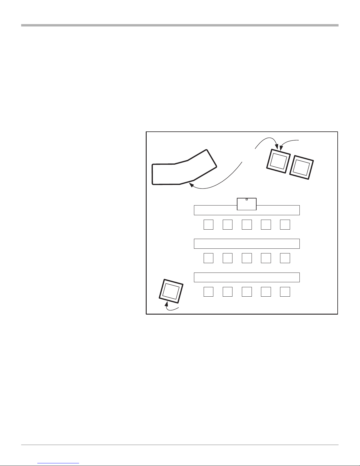
After the equipment has been unpacked, move each cart to its position within the room. For a typical room, the
following illustration shows approximately the recommended position of each cart and the AudioScience microphone
that is to be mounted on the ceiling.
Motion
Instructor desk/
Podium
Monitor
Touchpanel
Local
Monitor
2
Figure 2 Recommended Room Layout
To begin the installation:
Peripheral
equipment
cart
Director
microphone
(on ceiling)
Instructor
Monitor/Cart
AudioScience
microphone
(on ceiling)
Student
monitors/carts
1. Carefully place each monitor on its respective cart. Position the monitor in the center of the cart but no further
forward than indicated by the CAUTION label on the cart. Secure the rear of the monitor to the cart using the
strap provided.
WARNING: Even after the monitor has been secured to the cart by the rear strap, never move the cart by holding
the monitor.
2. Mount the TANDBERG WAVE camera on top of the left student monitor and the
Sony camera on top of the instructor monitor using Velcro strips. Three Velcro strips are provided in the camera
documentation package as well as an instruction sheet that shows where each strip is to be placed on the bottom
of the camera.
3. Install the AudioScience microphone as described by the installation procedures contained in Appendix 1.
12 Installation and Configuration Manual - D50103-06
Page 13
TANDBERG Educator
NAM and TAM Location
The NAM and TAM electronics are pre-mounted into sleeve modules. The sleeve modules are designed to be
installed by simply sliding into the shelf of the appropriate cart. Depending on the room configuration the following is
recommended:
• TAM module can be installed in the Instructor podium or in the Student monitor cart. The location of the TAM
module is normally dependent on the communication cabling and wall plugs. (Instructor Podium recommended as
1st option)
• The NAM module is installed in the Student monitors/cart.
• If the system is equipped with an
instructor monitor/cart, install the
additional NAM sleeve into the
instructor monitor/cart.
Instructor
podium
Possible TAM
module locations
NAM module
2
Instructors
monitors/carts
NAM module
AudioScience
microphone
(on ceiling)
Student
monitors/carts
Installation and Configuration Manual - D50103-06 13
Page 14

TANDBERG Educator
NAM and TAM Module Installation
To install the NAM and TAM modules perform the following steps:
Install the NAM module in the Student monitors/cart remove the back panel of the cart by using the key (provided
with the cart) and pushing on the lock.
1. Remove the back panel
2. Unscrew the thumbscrew on the top shelf.
3. Slide the NAM module into the top shelf.
4. Lock down the NAM module by replacing the thumbscrew.
Note: If the system is configured with an Instructor monitor/cart, install the NAM module using
the above steps.
5. Install the TAM module in the either the Instructor podium or Student monitors/cart remove the back panel of
the cart by using the key (provided with the cart) and pushing on the lock.
6. Remove the back panel
7. Unscrew the thumbscrew on the top shelf.
2
8. Slide the TAM module into the bottom shelf.
9. Lock down the TAM module be replacing the thumbscrew.
Educator/Tutor Extended
Height Cart (EHC-03)
Note: If you have the
Educator/Tutor Extended
Height Cart (EHC-03),
refer to Appendix 3 at the
end of this manual.
14 Installation and Configuration Manual - D50103-06
Page 15

TANDBERG Educator
Cabling
System cables are connected at the rear of the TAM, either directly to the Codec or to the interface panel. Connect
cables to the TAM as required. Coil any excess lengths of cable and place at the bottom of the carts.
2
1. Connect the TAM’s power cord from the TAM’s AC input socket to a suitable wall outlet.
2. If required, a power bar may be connected to the switched AC outlet of the TAM to provide switched power for
peripheral equipment.
Installation and Configuration Manual - D50103-06 15
Page 16

TANDBERG Educator
Student Monitors/Carts
Instructor Desk/
Podium
Optional
Peripheral
Equipment
Cart
Instructor Monitor/Cart
Instructor
Touch Panel
Cabling Configurations
Figure 3 shows the system cabling when the TAM is located in the Instructor podium.
Figure 4 shows the system cabling when the TAM is located in the Student cart. In this case, the AC power to the
student peripherals is not controlled by a power control unit, but instead the AC power is connected to a power bar
that is connected to the switched outlet of the TAM.
Student
Instructor Desk/
Podium
2
Optional
Peripheral
Equipment
Cart
Instructor
Instructor Monitor/Cart
Touch Panel
Figure 3 TAM Located in Instructor Desk/
Student Monitors/Carts
Figure 4 TAM Located in Student Cart
Podium
Touch Panel
Place the touch panel where it will be used such as on the instructor desk. Connect the touch panel cable to the
TOUCH PANEL connector on the TAM interface panel.
16 Installation and Configuration Manual - D50103-06
Page 17

TANDBERG Educator
Instructor
1. Connect the INSTRUCTOR cable to the INSTRUCTOR connector on the TAM interface panel. If the TAM is not
located close enough to the equipment, use a TANDBERG T510 extension cable.
2
2. Route the instructor cables to the instructor equipment and connect as follows:
i) Connect the cable labeled CAM VID OUT to the VIDEO
output connector of the camera.
ii) Connect the cable labeled CAM VISCA IN to the VISCA
IN control connector of the camera.
iii) Connect the cable labeled MOTION MON VID IN to the
VIDEO input of the monitor.
iv) Connect the cable labeled GRAPHIC MON VID IN to the
VIDEO input of the monitor, if equipped.
v) Connect the cable labeled TAM AUD IN to the AUDIO
input of the Natural Audio module or other suitable
amplified speaker.
vi) Connect the cable labeled PWR CTRL to the control input
of the power control unit. (North America only)
3. Plug the power cord of the instructor cart into a suitable
wall outlet. Connect a power bar to the power output of the
control unit. Use the power bar to power the instructor
equipment.
4. Connect the camera’s power cord from the DC IN 13.5V
power socket of the camera to the instructor power bar.
5. Plug the monitor’s power cord into the instructor power bar.
Educator/Tutor Extended
Height Cart (EHC-03)
Note: If you have the
Educator/Tutor Extended
Height Cart (EHC-03),
refer to Appendix 3 at the
end of this manual.
Installation and Configuration Manual - D50103-06 17
Page 18

TANDBERG Educator
Student
1. Connect the STUDENT cable to the STUDENT connector on the TAM interface panel. If the TAM is not located
close enough to the equipment, use a TANDBERG T510 extension cable.
2
2. Route the student cables to the student equipment and connect as follows:
i) Connect the cable labeled WAVE CAM to the WAVE camera.
ii) Connect the cable labeled MOTION MON VID IN to the VIDEO input of
the “motion” monitor, the monitor which will be displaying images from
the remote site.
iii) Connect the cable labeled GRAPHIC MON VID IN to the VIDEO input
of the “graphic” monitor, the monitor which will be displaying images
from local sources.
iv) Connect the cable labeled TAM AUD IN to the AUDIO input of the
Natural Audio module or other suitable amplified speaker.
v) Connect the cable labeled PWR CTRL to the control input of the power
control unit. (North America only)
Note: When the TAM is located in the student cart, the power control
unit is not used. In this case, peripherals are powered from a
power bar that is connected to the switched outlet of the TAM.
3. Plug the power cord of the power control unit into a suitable wall outlet.
Connect a power bar to the power output of the control unit. Use this
power bar to power the student equipment.
4. Connect the camera’s power cord to the student power bar. Use the
power adapter cable supplied with the system for the wave camera.
5. Plug the power cords of both monitors into the student power bar.
Educator/Tutor Extended
Height Cart (EHC-03)
Note: If you have the
Educator/Tutor Extended
Height Cart (EHC-03),
refer to Appendix 3 at the
end of this manual.
18 Installation and Configuration Manual - D50103-06
Page 19

TANDBERG Educator
AudioScience Microphone
2
1. See
2. Connect the AudioScience microphone cable to MIC 2 on the rear of the Codec.
3. An additional AudioScience microphone may be connected to MIC 3 on the rear of the Codec.
4. Set the Audio Input level in the “ Audio Setup Page”. A 19.5dB is a good nominal value.
Appendix 1: AudioScience Microphone.
Network
Connect the network cables that are applicable to the site. Refer to the VISION 6000 User Manual for more
information concerning other network equipment that may be required such as network terminating units and CSUs.
ISDN BRI
Connect each cable (labeled 1 to 6) within the ISDN BRI cable loom to the ISDN BRI sockets on the Codec. Then
connect the other end of the loom to the appropriate wall sockets. If however, the wall sockets provide an ISDN Uinterface, the ISDN lines from the Codec must first be connected to the S/T interface of network terminating units NT1
and NT384. Then connect the U interface of the network terminating units to the wall sockets.
ISDN E1/T1
Connect the E1/T1 cable to the E1/T1 socket labeled “1” on the Codec. Connect the other end of the cable to a
Channel Service Unit (CSU). Then connect the CSU to the site’s E1/T1 line.
External Network
Connect an RS366/V35/RS449 or X21 cable from NET on the Codec to CSU #1. Connect the CSUs to the
appropriate wall sockets.
Ethernet
Connect the LAN cable from the Ethernet connector on the rear of the Codec to the site’s Ethernet network
connection.
Note: For instruction concerning interface configuration, see: Ethernet Diagnostic Setup.
Installation and Configuration Manual - D50103-06 19
Page 20

TANDBERG Educator
Network Terminating Units NT1 and NT384 (North America only)
Install network terminating units when the site’s network provider ISDN BRI lines provides a U interface.
The U interface of the unit is connected to the outside network, and the S/T interface of the unit is connected to the
internal system network (Codec ISDN BRI connectors). The status of the ISDN lines can be determined by examining
the color-coded lamps that are on the font panel of each unit.
NT1
Lamp Indicates that:
U ACTIVE The outside line is available for use. (The U interface has been acquired.) This lamp may take up to 30 seconds to light.
S/T ACTIVE The internal ISDN equipment is ready. (The S/T interface has been acquired.)
NOT READY There is a problem with the U or S/T interface and it is not ready for data transmission. If this lamp remains lit, check
cabling and network connections.
NT384 (ISDN Lines 1, 2, and 3)
Lamp Indicates that:
Green The U and S/T interfaces are ready.
2
Orange The U interface is ready, but the S/T interface is not ready.
Red The U interface is not ready (therefore, the S/T interface is also not ready).
Network terminating unit model NT1 has two switches for configuration. These switches are factory set to the
configuration required by the Educator2 as follows:
S/T TERM (OHMS) is set to “100”
S/T WIRING is set to “LONG”
Installing Optional Equipment
The following installation procedures apply to specific models or types of optional equipment. If you are installing
equipment other than those described, consult the documentation supplied with that equipment.
Optional equipment must be enabled on the Equipment Setup page.
WARNING: Peripheral equipment may be powered from the switched power outlet on the TAM, provided that the 6A
rating of the TAM is not exceeded.
20 Installation and Configuration Manual - D50103-06
Page 21

TANDBERG Educator
Document Camera
The document camera option is a ELMO EV-Series with RS232 or a similar device. Installation instructions for the
TANDBERG Documentor are supplied with the camera.
Note: The Sony EVI-D30/31 document camera option is a custom configuration.
1. Place the document camera as appropriate.
2. Connect the DOC CAM cables to the TAM interface panel as follows:
i) Connect the cable labeled TAM I/P VIDEO DOC IN to the DOC IN VIDEO connector of the interface panel.
ii) Connect the cable labeled TAM I/P DOC CAM to the DOC CAM DB-9 control connector of the interface panel.
3. Route the DOC CAM cables to the document camera.
4. Connect the cable labeled DOC CAM VIDEO OUT to the VIDEO OUT connector of the document camera.
5. Connect the cable labeled DOC CAM RS232C to the RS232C connector of the document camera.
6. Plug the document camera’s power cord into an appropriate AC power outlet. This could be to a power bar that is
connected to the switched power outlet of the TAM.
7. If the ELMO EV-Series AF is being used set the document camera DIP switches 1 and 2 in the UP position.
2
VCR
For instruction on VCR configuration, refer to the: Installing Optional Equipment page.
If one VCR is used, connect as follows. If a DVD is being connected to the VCR input, ignore the output references:
1. Place the VCR on an equipment cart.
2. Connect the VCR cables to the TAM interface panel as follows:
i) Connect the cable labeled TAM I/P VCR VIDEO IN to the VCR IN VIDEO connector of the interface panel.
ii) Connect the cable labeled TAM I/P VCR VIDEO OUT to the VCR OUT VIDEO connector of the interface panel.
iii) Connect the cable labeled TAM I/P VCR AUDIO IN to the VCR IN AUDIO connector of the interface panel.
iv) Connect the cable labeled TAM I/P VCR AUDIO OUT to the VCR OUT AUDIO connector of the interface panel.
v) Connect the cable labeled TAM I/P VCR 1 to the VCR 1 DB-9 control connector of the interface panel.
3. Route the VCR cables to the VCR.
4. Connect the cable labeled VCR VIDEO IN to the VIDEO IN connector of the VCR.
5. Connect the cable labeled VCR VIDEO OUT to the VIDEO OUT connector of the VCR.
6. Connect the cable labeled VCR AUDIO IN to the AUDIO IN L/CH1 connector of the VCR.
7. Connect the cable labeled VCR AUDIO OUT to the AUDIO OUT L/CH1 connector of the VCR.
8. Connect the control cable labeled VCR RS2332C or S-LINK INor IR emitter to either the:
CONTROL-S connector of the VCR or over the IR receiver.
or
RS232C connector of the Panasonic VCR.
9. Plug the VCR’s power cord into an appropriate AC power outlet. This could be to a power bar that is connected to
the switched power outlet of the TAM.
Note: If a domestic VCR is used, connect all the cables as instructed above except for the control cable.
Installation and Configuration Manual - D50103-06 21
Page 22

TANDBERG Educator
If separate playback and record VCRs are used, connect as follows:
1. Place the VCRs on an equipment cart.
2. Connect the VCR cables to the TAM interface panel as follows:
i) Connect the cable labeled TAM I/P VCR VIDEO IN to the VCR IN VIDEO connector of the interface panel.
ii) Connect the cable labeled TAM I/P VCR VIDEO OUT to the VCR OUT VIDEO connector of the interface panel.
iii) Disconnect the cable labeled T302-0030 from the CODEC AUD IN 5. Connect this to the supplied audio
extension cable. The extension cable must be connected to AUDIO INPUT 2, left channel of the mixer.
iv) Connect the cable labeled TAM I/P VCR AUDIO IN from the MIXER OUTPUT to the VCR IN AUDIO connector of
the interface panel.
v) Connect the cable labeled TAM I/P VCR 1 to the VCR 1 connector of the interface panel.
vi) Connect the control cable labeled TAM I/P VCR AUDIO OUT to AUX 2 OUTPUT connector of the codec.
3. Route the VCR cables to the VCRs.
4. Connect the cable labeled VCR VIDEO IN to the VIDEO IN connector of “record” VCR.
5. Connect the cable labeled VCR VIDEO OUT to the VIDEO OUT connector of “playback” VCR.
2
6. Connect the cable labeled VCR AUDIO IN to the AUDIO IN L/CH1 connector of “record” VCR.
7. Connect the supplied cable from the to AUDIO OUT L/CH1 connector of “playback” VCR to the AUDIO INPUT 12,
left channel of the mixer.
8. To playback VCR locate the infrared sensor on the VCR.
9. remove the sticky tape backing on the emitter.
10. Place the emitter in front of the infrared sensor.
Note: If domestic VCRs are used, connect all the cables as instructed above except for the control cables.
DVD Player
To connect the DVD player as an auxiliary input:
1. Place the DVD player in an equipment cart.
2. Connect the AUXILIARY DVD cables to the AUXILIARY 1 connectors on the TAM interface panel:
i) Connect the cable labeled TAM I/P VIDEO AUX IN 1 to the VIDEO AUX IN 1 connector of the interface panel.
ii) Connect the cable labeled TAM I/P AUDIO AUX IN 1 to the AUDIO AUX IN 1 connector of the interface panel.
iii) Connect the cable labeled TAM I/P AUX 1 to the AUX 1 connector of the interface panel.
3. Route the AUXILIARY DVD cables to the DVD player.
4. Connect the cable labeled AUX VIDEO OUT to the VIDEO OUT connector of the DVD player.
5. Connect the cable labeled AUX AUDIO OUT to the AUDIO OUT connector of the DVD player.
6. To playback VCR locate the infrared sensor on the VCR.
7. remove the sticky tape backing on the emitter. (North America only)
8. Place the emitter in front of the infrared sensor. (North America only)
Note: If a domestic DVD player is used, connect all the cables as instructed above except for the control cable.
22 Installation and Configuration Manual - D50103-06
Page 23

TANDBERG Educator
Scan Converter (North America only)
An optional scan converter can be installed within a peripherals cart as follows:
1. Place the scan converter on a shelf within the cart.
2. Connect the cable labeled TAM I/P VIDEO AUX IN to the VIDEO AUX IN 1 or 2 connector of the TAM interface panel.
Note: If the Focus TView Gold scan converter is installed it is possible to control this device from the touch
panel. Connect the cable labeled TAM I/P AUX 1 IR to the AUX 1 DB-9 control connector of the I/O
panel. In addition, a sticky infrared emitter must be attached to the Focus TView Gold infrared window.
3. Connect the cable labeled AUX VID OUT to the video output connector of the scan converter.
4. Plug the scan converter’s power cord into an appropriate AC power outlet. This could be to a power bar that is
connected to the switched power outlet of the TAM.
35mm Slide to Video Converter (North America only)
The 35mm slide to video converter option is an Elmo TRV-35H or a similar device.
1. Place the slide to video converter as appropriate.
2. Connect the AUXILIARY TRV cables to the AUXILIARY 1 connectors on the TAM interface panel:
2
i) Connect the cable labeled TAM I/P VIDEO AUX IN 1 to the VIDEO AUX IN 1 connector of the interface panel.
ii) Connect the cable labeled TAM I/P AUX 1 to the AUX 1 connector of the interface panel.
3. Route the AUXILIARY TRV cables to the slide to video converter.
4. Connect the cable labeled AUX VID OUT to the VIDEO OUT connector of the slide to video converter.
5. Connect the cable labeled AUX 1 to the RS232C connector of the slide to video converter.
6. Plug the slide to video converter’s power cord into an appropriate AC power outlet. This could be to a power bar
that is connected to the switched power outlet of the TAM.
7. Set the slide to video converter DIP switches 1 and 2 in the UP position.
PC Presenter
VGA
1. Requires male-to-male VGA cable.
2. Connect one end of the cable to the VGA output of the PC.
3. Connect the other end of the cable to the Codec PC VGA in of the Educator2.
4. Make sure the PC is set to use its external VGA connection when using the laptop computer.
5. The PC Audio Output can be connected to the AUX IN 2 audio input if it is not being used by another device.
VNC
1. VNC requires LAN connection to the Codec.
2. VNC software must be installed on the PC.
Installation and Configuration Manual - D50103-06 23
Page 24

TANDBERG Educator
Pressure Mats
1. Install the pressure mats
connector box with double-
sided tape strips in a suitable
location near the TAM. Place
the pressure mats at desired
locations within the room. The
illustration shows some
possible locations for the mats.
2. Route the cables for each mat
along the walls of the room to
the connector box, connect
each cable to the connector
box. Note that the sockets are
labeled 1 to 5 and correspond
to the configured instructor
camera presets 1 to 5.
2
See section
3. Use tie wraps to neatly store any unused cable lengths.
For more information on setting camera presets, see the Educator2 User Manual.
Pressure Mats Configuration
to configure the pressure mats.
24 Installation and Configuration Manual - D50103-06
Page 25

TANDBERG Educator
TANDBERG Trackers
See
Appendix 2
Room Camera
The standard room camera is a Sony EVI-D30/31 with a wide-angle lens.
1. Install the wide-angle lens adapter to the camera.
2. Mount the room camera in the desired location such as on top of the right-hand side student monitor. Three Velcro
strips are provided in the camera documentation package as well as an instruction sheet that shows where each
strip is to be placed on the bottom of the camera.
3. Connect the cable labeled TAM I/P VIDEO AUX IN 1 to the VIDEO AUX IN 1 connector of the TAM interface panel.
4. Route the AUXILIARY cable to the room camera and connect it to the composite output connector of the camera.
Note: Connect the camera power cable from the DC IN 13.5V power socket on the camera to a suitable local
5. At the back of the camera, set the power switch to ON and the Backup switch to ON. Note that the Backup switch
must be ON for the camera presets to be saved when the system is powered down.
of this manual. Room Camera
power bar/supply. This could be to one of the power bars that provides switched power.
2
Telephone Add-on (North America only)
The installation to the telephone add-on unit is discussed in document – D50090 – By TANDBERG Inc. This
document is supplied with the telephone add-on assembly.
Touch and Talk Microphones (North America only)
The installation of the Touch and talk microphones is discussed in document – D5012803 – By TANDBERG Inc. This
document is supplied with the TNT equipment.
The Director Microphone
This ceiling mounted microphone replaces the touch panel microphone.
1. See
2. Remove the existing touch panel microphone cable from the MIC 1 on the rear of the Codec.
3. Connect the Director microphone cable to MIC 1.
Set the Audio Input level in the Audio Setup Page. A 19.5dB is a good nominal value.
Appendix 1: AudioScience Microphone
for assembly and installation.
Installation and Configuration Manual - D50103-06 25
Page 26

TANDBERG Educator
System Configuration
To configure the system, turn it ON by pressing SYSTEM ON in the upper left corner of the bezel. When power is
applied to the system, the touch panel appears as follows:
2
Figure 5 Touch Panel Opening Page
The “Please Wait” message appears while the system is loading. When the system has loaded, “Touch to Start”
appears. Press Touch to Start to open the Main Operating page.
Protected Setup Page
The protected setup page is only used to adjust the time and date. The page is accessed by pressing the very bottom
left corner of the opening page.
WARNING: Changes to the protected setup will affect the operation of Educator2.
Please note that on the Protected Setup page, BEEP must be set to 0.
Time and Date
To set the time and date:
1. Access the Protected Setup page.
2. Press SET TIME AND DATE.
3. Use the up and down buttons to change the time and date as necessary.
26 Installation and Configuration Manual - D50103-06
Page 27

TANDBERG Educator
System Set Up Button
Press SYSTEM SETUP and either the Main System Setup page or a key pad will appear on the screen. The key
pad will only appear if the Password option has been selected in the System Setup page. To access the
configuration pages when the password protection is active, you must enter the password on the key pad and press
Enter. To return to the Main Operating page without entering a password, press Cancel.
If the proper password is entered, a compilation progress message window will appear followed by the System Setup
Main page.
A button for each of the
six pages is displayed at
the top of screen so that
any page can be directly accessed. The button of the active page is displayed in green. By default, the first page to be
displayed is Equipment Setup. The following sections explain how to use each page.
An EXIT button is also located at the top of the screen. When you have finished making
changes to the system configuration press EXIT. The system configuration will be updated and
the Main Operating page will be displayed.
2
Key Pad
The key pad will be displayed when numeric inputs such as the password, ISDN line numbers, etc., are required.
Button Functions
0-9, *, # Press the number keys as required.
Delete Erases the last character entered.
Cancel Discards any key pad entry and closes the key pad
window.
Enter Accepts the key pad entry and closes the key pad window.
Installation and Configuration Manual - D50103-06 27
Page 28

TANDBERG Educator
Terminal Setup Page
Press TERMINAL SETUP to display the
Terminal Setup page (see following
figure). Different options will be
displayed for configuring the ISDN-BRI/
PRI, Leased Line and External networks
as shown in Figure 6.
For each installation of the Educator2, it
is necessary to select the correct
Network Type before making a call. In
addition, you must program your
network settings in order to be able to
answer or make calls.
Figure 6 Terminal Setup Page (ISDN-BRI Settings)
2
Buttons Functions
ISDN-BRI Operates the system by means of ISDN-BRI.
ISDN-PRI Operates the system by means of ISDN-PRI.
External Press to use special networks and connect using RS449, V.35, or X.21.
Press to connect to ISDN by means of an external IMUX.
Leased E1/T1 Operates the system by means of Leased E1/T1.
Ethernet H323 & IP Setup Configures the Codec IP address and H323 Settings. When active H323 IP calls may be made.
Call Control Configures the Auto Answer and Do Not Disturb functions and accepts MCU calls, see figure 12.
Currently active functions will be displayed in the button body (DND, AutoAns, MCU Accept)
Download Codec Directory Downloads the information stored within the Codec local or global call directories to the touch panel. This function
can be used to restore speed dial information after a system upgrade.
Figure 7 Set Up Call Control Options
28 Installation and Configuration Manual - D50103-06
Page 29

TANDBERG Educator
ISDN-BRI Settings
Press ISDN-BRI in the CURRENT NETWORK panel of the Terminal Setup page to display this network’s control
options.
2
Figure 8 Terminal Setup ISDN-BRI Settings Page
Switch Type
Buttons Functions
Enable Switch Type Enables (activates) the switch type that is displayed in the switch type window.
Arrows Scrolls through the available switch types. The Enable Switch Type button is green when the active switch type is
(up/down) displayed in the window.
ISDN-BRI Settings
Use the arrows to select a line for which you will enter numbers. The line display window in the ISDN-BRI SETTINGS
box shows the currently selected line. Press ENABLE LINE to enable the line. The Enable Line button is green when
the active line is displayed in the window.
Buttons Functions
Arrows Scrolls through the available ISDN-BRI lines for which data is to be defined. The currently selected line appears in the line
(left/right) display window in the ISDN-BRI SETTINGS box.
Enable Line Activates the currently selected ISDN-BRI line in the Codec.
Auto SPID Detect When the switch type is set for National ISDN, the Auto SPID Detect function window will be displayed. When selected the
system will automatically configure the BRI number and SPID settings.
First Number Configures or displays the first ISDN-BRI number. A key pad appears, use as described in Key Pad.
Second Number Configures or displays the second ISDN-BRI number. A key pad appears. This button will not work unless the first number
is entered.
First SPID Configures the first SPID number. A key pad appears, use as described in Key Pad.
Second SPID Configures the second SPID number. A key pad appears. This button will not work unless the first number is entered.
Installation and Configuration Manual - D50103-06 29
Page 30

TANDBERG Educator
Advanced Setup
Buttons Functions
Press the button to display the Advanced Call Setup screen. Select as many options as required from the advanced
setup panel.
Parallel Dial performs a parallel dial. If set to ON (illuminated), dialed channels will be connected in parallel when setting
up a Bonding call.
Downspeed enables the Downspeed feature. When enabled (illuminated), the system will automatically adjust to the
maximum available bandwidth.
Send Own Numbers will send the Educator’s own number to the remote site.
Access Code the user will be prompted to enter an access code before gaining access to the call controls.
Subaddress enters a Subaddress if ETSI or 1TR6 is selected as the switch type. Subaddress enables up to 8 ISDN
terminals to be connected to the same ISDN line; each terminal is given a unique subaddress. A key pad appears, use as
described in Key Pad. For use in Europe only.
Validate Numbers MSN uses Multi Subscriber Network (MSN). MSN enables the user to attach different ISDN
terminals, with different numbers, to the same physical ISDN line. For use in Europe only.
2
Fallback to a telephone call connects to a telephone (audio only) call if the call can not connect on video.
Accept a telephone call allows the system to connect automatically to incoming telephone calls.
H320 DES Encryption Point To Point Only if the far end system supports encryption, when enabled the system will
attempt to send encrypted data. This operation is a part of the codec call negotiation and requires no further user
intervention.
Note: If the far end system does not support encryption, the call will proceed without encryption.
Call Quality
Button Function
Pressing this button displays the Call Quality Configuration Screen (see: Figure 12).
This allows the Codec to be set to make a specific type of call. The Codec will negotiate with the remote site using the
given call parameters.
Default Call Quality is the number of channels the system will attempt to call at unless changed using the ‘Quality’
function on the dialing page.
Video Resolution: QCIF: Low resolution video (176 x 144 pixels). CIF: High-resolution video (352 x 288 pixels). iCIF: CIF
resolution at 60 fields/sec. 4CIF: Highest resolution (704 x 576 pixels). AUTO: Allows the system to set the optimal
resolution.
Video Mode: H.261: Normal video compression and decompression. H.263: Bandwidth efficient video compression and
decompression. AUTO: Allows the system to set the optimal quality.
Audio Mode: G.728: Compressed normal quality audio leaving more bandwidth for video. G.711: Normal quality audio
(telephone quality, 3.1 kHz). G.722 and G.722.1: High quality audio (7 kHz). AUTO: Allows the system to set the optimal quality.
Optimize- Quality is a speed button, which sets all three elements to AUTO. AUTO lets the Codec determine the best call
parameters to use.
LOCK prevents the call quality controls from being used on the Call Status Control page. Press LOCKED to re-enable
these buttons.
30 Installation and Configuration Manual - D50103-06
Page 31

TANDBERG Educator
ISDN-PRI Settings
Press ISDN-PRI/T1 in the CURRENT NETWORK panel of the Terminal Setup page to display this network’s
control options.
2
Figure 9 Terminal Setup ISDN-PRI Settings Page
Switch Type
Buttons Functions
Enable Switch Type Enables (activates) the switch type that is displayed in the switch type window.
Arrows Scrolls through the available switch types. The Enable Switch Type button is green when the active switch type is
(up/down) displayed in the window.
ISDN-PRI Settings
Buttons Functions
Number Programs the main number for the ISDN-E1/T1 line. Enter the number on the keypad; use as described in Keypad.
Max Channels Use the arrow keys to specify the maximum number of channels available from the T1 CSU. The current maximum
number of channels will be displayed in the white text box.
Cable Length Use the arrow keys to specify the distance from the Educator2 to the CSU. The current length will be displayed in the
white text box.
Cascade Cable Length Use the arrow keys to specify the length of the cascading cable. The current length will be displayed in the white text box.
NSF Your network provider may require a service selection in your ISDN configuration. To select the NFS code for a Video and
Non Standard Facility Telephone calls, press the Change button.
Valid NSF service codes are from 1 to 31. Enter 0 to disable NSF service codes.
Example: AT&T offers several digital switched services. These include SDN with service code 1 and ACCUNET with
service code 6.
Installation and Configuration Manual - D50103-06 31
Page 32

TANDBERG Educator
Advanced Setup
Buttons Functions
Pressing this button displays the Advanced Configuration Screen. Select as many options as required from the
advanced Setup Panel.
Note: The Advanced Setup window has ‘green’ and ‘red’ indicators to show which settings are on or off.
Subaddress enters a Subaddress if ETSI or 1TR6 is selected as the switch type. Subaddress enables up to 8 ISDN
terminals to be connected to the same ISDN line; each terminal is given a unique Subaddress. A key pad appears, use as
described in Key Pad. Only used in Europe.
Parallel Dial performs a parallel dial. If set to ON (illuminated), dialed channels will be connected in parallel when setting up a
Bonding call.
Downspeed enables the Downspeed feature. When Enabled (illuminated), the system will automatically adjust to the
maximum available bandwidth.
Validate Numbers MSN uses Multi Subscriber Network (MSN). MSN enables you to attach different ISDN terminals, with
different numbers, to the same physical ISDN line. Only used in Europe.
Fallback to a telephone call connects to a telephone (audio only) call if call cannot connect on video.
Send Own Numbers Sends the Educator’s own numbers to the remote site.
2
Accept a telephone call allows the system to connect automatically to incoming telephone calls.
Access Code the user will be prompted to enter an access code before gaining access to the call controls.
H320 DES Encryption Point To Point Only if the far end system supports encryption, when enabled the system will
attempt to send encrypted data. This operation is a part of the codec call negotiation and requires no further user
intervention.
Note: If the far end system does not support encryption, the call will proceed without encryption.
Call Quality
Button Function
Pressing this button displays the Call Quality Configuration Screen (see Figure 12).
This allows the Codec to be set to make a specific type of call. The Codec will negotiate with the remote site using the
given call parameters.
Default Call Quality is the number of channels the system will attempt to call at unless changed using the ‘Quality’
function on the dialing page.
Video Resolution: QCIF: Low resolution video (176 x 144 pixels). CIF: High-resolution video (352 x 288 pixels). iCIF: CIF
resolution at 60 fields/sec. 4CIF: Highest resolution (704 x 576 pixels). AUTO: Allows the system to set the optimal resolution.
Video Mode: H.261: Normal video compression and decompression. H.263: Bandwidth efficient video compression and
decompression. AUTO: Allows the system to set the optimal quality.
Audio Mode: G.728: Compressed normal quality audio leaving more bandwidth for video. G.711: Normal quality audio
(telephone quality, 3.1 kHz). G.722 and G.722.1: High quality audio (7 kHz). AUTO: Allows the system to set the optimal quality.
Optimize- Quality is a speed button, which sets all three elements to AUTO. AUTO lets the Codec determine the best call
parameters to use.
LOCK prevents the call quality controls from being used on the Call Status Control page. Press LOCKED to re-enable
these buttons.
32 Installation and Configuration Manual - D50103-06
Page 33

TANDBERG Educator
External Network Settings
Press External in the CURRENT NETWORK panel of the Terminal Setup page to display the External Network
controls.
2
Figure 10 External Setup Page
Call Control
Buttons Functions
RS366 Dialing Enables RS366 dialing from the system, and is normally used together with network clocking. RS449/V35 compatible
when the external equipment uses RS366 ports.
Leased Line This is a non-dialing protocol and should be used when two Codecs are connected in a point to point connection.
Data Triggered This mode uses TXData, RXData and clock signals only. Use this mode when no handshake signals are available.
Manual This mode should be used when no handshake signals are available, and the external equipment requires a constantly
connected line.
Network Clocking
Buttons Functions
RS449/ V35 Compatible Use when the external equipment provides two clock signals: one for transmit and one for receive.
X.21 Compatible Use when the external equipment provides a common clock signal for both transmit and receive.
Installation and Configuration Manual - D50103-06 33
Page 34

TANDBERG Educator
Leased E1/T1 Description
Press Leased E1/T1 in the
CURRENT NETWORK panel of the
Terminal Setup page to display the
Leased E1/T1 network control
options.
2
Figure 11 Leased E1/T1 Page
Network Type
Buttons Functions
E1/T1 Switch Type Enables the system type E1 (30 channels) or T1 (24 channels). E1 will be default for PAL versions and T1 will be default
for NTSC versions.
MAX Channels Indicates the maximum number of channels the Codec is allowed to use on the E1/T1 interface. When E1 is selected, the
maximum number of channels is 30. When T1 is selected, maximum number of channels is 24. Use the Change button
to specify the number of channels to be used by the system.
Start Channel Indicates the first E1/T1 channel the Codec is allowed to use. This setting might be used if the E1/T1 line is shared with
other equipment. Use the Change button to specify the number of channels to be used by the system.
Leased T1/E1 Settings
Buttons Functions
LEASED T1 SETTING
Line Coding Indicates how the signals on the line should be coded. If parts of the line between the systems use restricted coding, this
should be selected.
Note: All settings must be identical on both sides of the T1 connection.
Cable Length Use the arrow keys to specify the distance from the Educator2 to the CSU. The current length will be displayed in the
white text box.
LEASED E1 SETTING
E1 CRC-4 CRC-4 is used for most E1-PRI configurations. You can turn it off if not supported by your E1 network equipment.
34 Installation and Configuration Manual - D50103-06
Page 35

TANDBERG Educator
Call Quality
Button Function
Pressing this button displays the Call Quality Configuration Screen (see Figure 12).
This allows the Codec to be set to make a specific type of call. The Codec will negotiate with the remote site using the
given call parameters.
Default Call Quality is the number of channels the system will attempt to call at unless changed using the ‘Quality’
function on the dialing page.
Video Resolution: QCIF: Low resolution video (176 x 144 pixels). CIF: High-resolution video (352 x 288 pixels). iCIF: CIF
resolution at 60 fields/sec. 4CIF: Highest resolution (704 x 576 pixels). AUTO: Allows the system to set the optimal resolution.
Video Mode: H.261: Normal video compression and decompression. H.263: Bandwidth efficient video compression and
decompression. AUTO: Allows the system to set the optimal quality.
Audio Mode: G.728: Compressed normal quality audio leaving more bandwidth for video. G.711: Normal quality audio
(telephone quality, 3.1 kHz). G.722 and G.722.1: High quality audio (7 kHz). AUTO: Allows the system to set the optimal quality.
Optimize- Quality is a speed button, which sets all three elements to AUTO. AUTO lets the Codec determine the best call
parameters to use.
LOCK prevents the call quality controls from being used on the Call Status Control page. Press LOCKED to re-enable
these buttons.
2
Figure 12 Call Quality Configuration Screen
Installation and Configuration Manual - D50103-06 35
Page 36

TANDBERG Educator
Ethernet H.323 & IP Setup
Press Ethernet H.323 & IP Setup in the CURRENT NETWORK panel of the Terminal Setup page to display the
controls for configuring the IP addresses. The controls are:
2
Figure 13
Ethernet
Diagnostic
Setup Page
DHCP
Buttons Functions
DHCP Enables the Codec to automatically receive all the necessary address information from the DHCP server.
Static De-activates the (Dynamic) DHCP and allows manual configuration of the IP address and Subnet mask IP and
Gateway addresses.
Current Active IP Status
When Static Assignment is active the following buttons are available for IP configuration.
Buttons Functions
IP Address Press to enter the IP address using pop-up key pad.
Subnetmask Press to enter the Subnetmask IP address using pop-up key pad.
Gateway When using the dynamic assignment, press to manually enter the gateway IP address that will override the gateway IP
address provided by the DHCP server.
When using the static assignment, press to manually enter the gateway IP address.
NAT
Buttons Functions
NAT Router Press to enable network address translation if the Codec is connected to a NAT router.
NAT Address Press to enter the global/external IP address of the NAT router.
36 Installation and Configuration Manual - D50103-06
Page 37

TANDBERG Educator
Gatekeeper & Routing Settings
2
Buttons Function
No The Codec will not use a gatekeeper and an IP-address must be used in order to make an H.323 call.
Auto The Codec will automatically try to register on any available gatekeeper. If a gatekeeper responds to the request sent
from the Codec within 30 seconds, this specific gatekeeper will be used. If no gatekeeper responds, the Codec will not
use a gatekeeper for making H.323 calls and hence an IP-address must be manually specified.
Manual The Codec will use a specific gatekeeper specified using the ‘Gatekeeper IP-address’
H323 Alias This is the H323 address of the Codec. The H323 address is equivalent to a telephone number, sometimes combined
with access codes. Valid characters are 0-9, * and #. Pressing the H323 Alias button allows access to numeric keypad,
where an alias number can be entered. When using a gatekeeper, the Codec will send a message to the gatekeeper
containing both H323 address and the system name of the Codec. The Codec will not register with the gatekeeper if the
H323 alias is not set.
Gatekeeper IP This is the gatekeeper IP-address if you specify ‘manual’
RSVP This can be enabled and disabled from the System Setup > Terminal Setup > Ethernet > Gatekeeper/Routing. RSVP
(Resource Reservation
Protocal)
IP Precedence Press the Change button to select a routing path for the router when multiple paths are available.
guarantees IP bandwidth over supported Cisco networks; i.e. if you placed a 768K call, you will get 768K for the duration
of the conference.
• Off: Disables routing
• Delay: Tells router to minimize the delay
• Cost: Tells the router to minimize the cost
• Reliability: Tells the router to maximize the reliability
• Throughput: Tells the router to maximize the throughput
IP TOS Press the Change button to select a routing path for the router when multiple paths are available.
Installation and Configuration Manual - D50103-06 37
Page 38

TANDBERG Educator
Streaming
2
Buttons Function
Enable on Call Control This button allows you to enable streaming on the call Control/Status and Manual Dial pages.
Start Streaming is started using Quick button “Start”. To stop streaming, press the Start button again.
Address The window next to the Address button displays the current IP address on the system, a streaming server or a multicast
address. To change the IP address setting, press the Address button and enter the IP address on the keypad.
Address Port The window next to the Address Port button displays the current Address Port. To change the address port setting, press
the Address Port button. If several Codecs are streaming to the same IP address, different ports have to be used in
order for the client to select which stream to receive. If the first Codec streams on port 2240 and the second Codec on
port 2250, you have to specify which port to listen to. Video is transmitted on the specified port, audio is transmitted on
the port number 4 above the specified video port.
Router Hops This is used for streaming data to limit how many routers the data should pass before it is rejected. The window next to
the Router Hops button displays the current setting. To change the number of hops setting, press the Router Hops
button. If set to two, data will not traverse more than two router hops.
Remote Start • On: Streaming can be started from external user interfaces like the Web and Telnet.
• Off: Streaming can only be started via the Touch Panel. This will prevent activation of streaming using
the Web or Telnet. Use the arrow key to select the desired video rate
Transmit Sources • Auto: Streams whichever is speaking, the local or remote site.
• Local: Streams the local site live source.
• Remote: Streams the image from the remote site.
Restart
After any changes to the configuration, the Restart button must be activated for these changes to take effect.
Button Functions
Restart This button will reboot the Codec allowing the implemented changes to take effect. While this is happening the button will
flash, during this time do not use the system.
38 Installation and Configuration Manual - D50103-06
Page 39

TANDBERG Educator
Equipment Setup Page
The Equipment Setup page is the default page that appears when SYSTEM SET UP on the bezel is pressed. (The
Equipment Setup page is active when the EQUIPMENT SETUP button is green.) A selected button goes from gray to
green indicating that the source/option is active. When a source is selected, the box on the right of the screen
displays any options that are available for that source.
2
Figure 14
Equipment
Setup Page
Buttons Functions
Student Camera Enables or disables as required. Enabled source appears in the Live Source panel on the Main Operating page and in the
Full Screen Preview mode.
Instructor Camera Enables or disables as required. Enabled source appears in the Live Source panel on the Main Operating page and in the
Full Screen Preview mode.
Document Camera Enables or disables as required. Enabled source appears in the Live Source panel on the Main Operating page and in the
Full Screen Preview mode.
VCR or DVD Enables or disables as required. Enabled source appears in the Live Source panel on the Main Operating page and in the
Full Screen Preview mode.
Auxiliary #1 Enables or disables the source installed as AUX 1.
Auxiliary #2 Enables or disables the source installed as AUX 2.
PC Presenter Enables transmission of the Codec VGA input.
(Codec VGA In or VNC)
Note: Accepts VGA signal (640 x 480) or S-VGA (800 x 600) signal or X-VGA signal (1024 x 768).
The PC Audio can be connected to Audio Aux In 2.
Pressure Mat You may set a video switch and/or camera movement for each of the five pressure mats.
Exit Returns to the Main Operating page. This can take several seconds as the system is compiling the changes to the related
equipment.
Installation and Configuration Manual - D50103-06 39
Page 40

TANDBERG Educator
Student/Instructor Camera
Select the Student Camera or Instructor Camera button and a pop-up window appears in the right part of the screen
(see figures below). Select and set the cameras here.
2
Buttons Functions
Rename Source Press Rename Source if you want to change the name of the camera, as it will appear on the Main Operating page. If
the Rename Source button is active here, the Student/Instructor camera source will read MAIN Camera
External Control Use when camera type not available in the Educator2, is installed.
Parkervision Fully controlled from the Touch Panel. Activate Auto Tracking button
TANDBERG WAVE/ Fully controlled from the Touch Panel. Set the camera’s brightness (Iris), White Balance by pressing Sony/Wave Setup.
Sony EVI-D30/31 Camera type is automatically detected.
Sony EVI-D100
Another No Control Another camera can be used with the system but it will not have the Touch Panel control. The Touch Panel will only
switch the video input source
To set up the Instructor or Student Camera:
1. On the Equipment Setup page, select Instructor Camera or Student Camera
2. On the Camera Type screen, select the camera type.
3. (Optional) Change the name of the camera button using Rename Source. If you do not change the name here,
the camera source will be labeled as Instructor Camera or Student Camera on the Main Operating page. To
change the name, press Rename Source. Type in the new name using the pop-up keypad. Press Exit when
done.
4. Set the camera’s brightness by pressing its accompanying control button (see the following sections).
5. Press Exit.
40 Installation and Configuration Manual - D50103-06
Page 41

TANDBERG Educator
Sony/Wave Camera Setup (Student, Instructor)
Use the camera controls to manually set the Iris / Gain setting of the Sony EVI-D30/31 camera. This feature allows
you to de-activate the default Auto-Iris setting on the camera and manually set it for difficult situations; for example,
where the foreground and background are illuminated differently.
2
Buttons Functions
• Auto:
Iris Arrow Down • Arrow Up: Press to select the brightness setting
• Arrow Down:
• Reliability:
White Balance • Mode 1: Press to select the white balance setting
• Mode 2:
More Enables or disables the iris and focus control of the camera from the Main Operating page
Exit Closes the pop-up window and returns to the Equipment Setup page.
Installation and Configuration Manual - D50103-06 41
Page 42

TANDBERG Educator
Document Camera
Pressing the Document Camera button opens a pop-up window in the right part of the screen. Select a document
camera. The choices are as follows:
2
Buttons Functions
Wolfvision VZ-series Provides zoom, focus and iris controls.
Elmo EV-400AF Provides zoom, focus, lighting and image controls.
Elmo EV-4400AF Provides zoom, focus, lighting and image controls.
Sony P-110 Provides zoom, focus, lighting and image controls.
DC2000 Documentor Provides Zoom and focus controls.
Another No Control Does not have touch panel controls. The video output is made available to the system and any adjustments must be done
using the controls on the camera.
None No document camera installed
The name of the camera selected appears in the document camera button on the Main Operating page. Press Setup
to make any adjustments. Press Exit to return to the Equipment Setup page.
42 Installation and Configuration Manual - D50103-06
Page 43

TANDBERG Educator
VCR or DVD Player
Pressing the VCR or DVD button opens a pop-up window in the right part of the screen. Select the applicable VCR or
DVD player.
2
Device Controls
(DVD) • Sony DVD Touch panel provides play and transport controls.
• Panasonic IR DVD Touch panel provides play and transport controls.
(VCR) • Sony VCR Touch panel provides play, record and transport controls.
• Panasonic IR VCR Touch panel provides play, record and transport controls.
• Panasonic AG-5700/10 Touch panel provides play, record and transport controls.
• Another No Control Does not have touch panel controls. The video output is made available to the system and
any adjustments must be done using the controls on the device.
None No VCR installed.
Press Separate Play/Rec VCRs to indicate that there are two separate VCRs
performing the playback and record functions. These VCRs, if controlled from the touch
panel, can only be the Sony or Panasonic model.
Press VCR/DVD control mode to configure the Sony VCR or DVD control interface.
On the pop-up window select whether the Sony device you are using has a S-Link or IR control
input.
Press Exit to return to the Equipment Setup page.
Installation and Configuration Manual - D50103-06 43
Page 44

TANDBERG Educator
Auxiliary Device #1
Press the Auxiliary Device #1 button to set the device attached to the AUX#1
port. Select the applicable auxiliary device from the pop-up window in the right
part of the screen. The choices are as they appear in the following screen.
Use the Device Control button that pops-up to the right of the source to access
device’s controls on the Main Operating page.
Press VCR/DVD control mode to configure the Sony VCR or DVD control
interface.
On the pop-up window select whether the Sony device you are using has a SLink or IR control input.
Name Model that can be controlled
(DVD) • Sony DVD Sony DVP 300S
• Panasonic IR DVD Panasonic DVD-RV series
35mm Slide/Video Elmo TRV-35H
2
PC Scan Converter Focus Tview Gold
Room Camera Sony EVI-D30/31
Use the Device Control button that pops-up to the right of the source to access device’s controls on the Main
Operating page.
Press VCR/DVD control mode to configure the Sony VCR or DVD control interface.
On the pop-up window, select whether the Sony device
you are using has a S-Link or an IR control input.
Room Camera Setup
Use the room camera positioning and zooming controls to
set the room camera. Make the appropriate changes, then
press Save to store the settings. This sets the power up
location of the camera. Even if the camera settings are
then changed, the camera will return to this position the
next time it is powered ON.
Buttons Functions
Arrows Move the camera up, down, left and right.
IN Zooms in (enlarges the view of the subject).
OUT Zooms out (reduces the view of the subject).
Save Stores the power up location of the document camera.
Image Adjust Removes the pan left, right and zoom controls, and changes the text of the Save button to Auto Iris. The remaining up & down
keys adjust the Iris / Gain setting of the camera and de-activate the Auto-Iris function. Select Auto Iris to cancel the previous iris
setting and return the camera to the default Auto-Iris mode. Select Image a second time will display the setup shown above.
Exit Closes this pop-up window and returns to the Equipment Setup page.
44 Installation and Configuration Manual - D50103-06
Page 45

TANDBERG Educator
Auxiliary Device #2
Press the Auxiliary Device #2 button to set the device attached to
the AUX#2 port. Select the applicable auxiliary device from the popup window in the right part of the screen. The choices are as they
appear in the following screen.
The PC audio from the PC Presenter can also be connected to the
Audio Aux In 2. This Audio function ONLY works when the A/V Input
or PC Scan Converter button is not selected.
The icon to the left of the selected device is what will appear on the
Auxiliary #2 button on the Main Operating page
Pressure Mats Configuration
The Pressure Mats feature allows the system to switch to a preset
and/or video source automatically. Press the Pressure Mats button
on the Equipment Setup page to access this camera configuration.
This page allows the pressure mats to be assigned to the main
camera presets and/or the selection of the video sources such as
document camera or PC Input.
2
Buttons Functions
STEP ON Camera Move Press the Call Preset 1-5 to activate the assigned main camera presets.
Video Switch Press to toggle through the desired video source that will be transmitted when selected.
STEP OFF Camera Move Set the action/source that will occur/display when stepping off the pressure mats.
Video Switch Indicates the video source that will be transmitted when the user steps off the pressure mat.
Temporary Disable Control When activated, the user will be able to disable the operation of the mats temporarily from the Main Page.
Example 1, See diagram:
When the Instructor steps on the
pressure mat #1, the Instructor
Camera will go to Preset 1 and
the also transmit the image of the
Instructor since the Video
Switch is selected. When the
Instructor steps off the pressure
mat, the instructor camera will go
back to the prior setting and zoom
out to a wider view.
Example 2, See diagram:
When the Instructor steps on the
pressure mat #3, the Instructor
Camera will go to Preset 3 and
the also transmit the image of the
Document since the Video
Switch is selected. When the
Instructor steps off the pressure
mat, the instructor camera will go
back to the Preset 6.
Installation and Configuration Manual - D50103-06 45
Page 46

TANDBERG Educator
Audio Setup Page
Press AUDIO SETUP on the Main System
Setup page to display the Audio Setup page.
Use this page to view and change the settings
and levels for each audio input and output.
Telephone Add-on
(North America only)
The Telephone Add-on feature allows the
telephone caller to be brought into the
videoconference call. Press the button on
the Audio Setup page to make this option
available. Once activated, this option will be
accessible on the Live Sources panel of the
Main Operating page and on the Call
Status Control page.
Figure 15 Audio Setup Page (with Input selected)
2
Button Functions
Telephone Add-on Enables and disables the Telephone Add-on option.
To make a telephone only call, dial the remote party using the Telephone Handset. Press the Telephone Add-on button
to connect the call into the conference. The button will illuminate and the “Tel-Add” indicator will flash when the
telephone party is connected. Press Telephone Add-on again to disconnect the call.
Audio Input Settings
Level E N M A
C R I G
XC
Audio Source Audio Level Echo Canceller Noise Reduction Mix Mode Automatic Gain Control
Select to configure that
audio input.
Mic. 1 - Podium
Mic. 2 - AudioScience 1
Mic. 3 - AudioScience 2
Audio 4 - PTT Mixer
Audio 5 - Tel-add or Aux.
Audio 6 - VCR or DVD
Displays the
corresponding
audio input
level in dB.
These lights
indicate if the
echo canceller
is active for
the audio
input.
These lights
indicate if the
noise filter is
active for the
audio input.
These lights
indicate if the
input levels for
the microphones
and Audio 4 are
automatically
controlled. If the
lights are off, the
input levels are
fixed (all active).
These lights
indicate if the AGC
is active for the
audio input.
Mic 1, 2, 3, and
Audio 4 share the
same AGC circuit.
Audio 5, 6, and
Received Audio
have individual
AGC circuits.
Note: Selecting a particular Audio Input causes that input’s setup window to appear in the center of the screen.
46 Installation and Configuration Manual - D50103-06
Page 47

TANDBERG Educator
Audio Output Settings
Audio Output Level
Select to configure that audio output. Displays the corresponding audio level in dB.
Audio 1 - Room Loud Speakers
Audio 2 – Telephone Add-on
Audio 3 - VCR
Note: Selecting a particular Audio Output causes that output’s setup window to appear in the center of the screen.
Input/Output Controls
Buttons Functions
Text Window Indicates what is being configured.
Level Up / Down Adjusts the level of the audio input in 1.5 dB steps. The current value is displayed in the ‘Level’ window.
Channel On / Off Activates or de-activates that audio input.
2
Customized Mute Control Press to activate or de-activate the audio input as a custom mute. If any microphone audio inputs is enabled, the
Customized Mute Control will be displayed on the Main Operating page replacing the Date button.
Echo Control Activates or de-activates that audio input’s echo canceller.
Noise Reduction Activates or de-activates that audio input’s echo canceller with low frequency noise filter.
AGC On / Off Activates or de-activates that audio input’s automatic-gain-control.
Mic 1, 2, 3, and Audio 4 share the same AGC circuit. Audio 5, 6 and Received Audio have individual AGC circuits.
Mix Mode Auto Toggles the mix mode ON and OFF. When set to ON, the input levels of Mic 1, 2, 3, and Audio 4 are automatically
controlled. To reduce background noise, microphones that are not picking up the current speaker will have their input
levels lowered. When the mix mode is OFF, all four inputs are constantly active.
Installation and Configuration Manual - D50103-06 47
Page 48

TANDBERG Educator
Room Properties
The Room Properties feature allows you to set the optimization of the echo canceller to the acoustic size of the room.
Hard walls, many windows etc. might require higher settings than expected. Carpets, curtains etc. might require a
lower setting. Adjust the setting if one of the following symptoms occurs at the far end or remote site:
Size of the Room
• There is still echo of your own audio. Press the Change button of the ROOM PROPERTIES window. In the
popup window, use the up arrow key to increase the value.
• The system adapts slowly to the acoustic changes in the room. Press the Change button of the ROOM
PROPERTIES window. In the popup window use the down arrow key to decrease the value.
Motion within the Room
• If you experience echo caused by motion.
Press the Change button of the ROOM PROPERTIES window. In the popup window, use the up arrow key to
increase the value.
Restore Audio Defaults
2
This button resets all the audio inputs and outputs to the Codec default conditions, which are:
• All audio inputs - On
• All echo cancellers (EC) - On
• Noise Reduction (NR) - On
• Mix Mode (Mix) - On
• All system Automatic Gain Control (AGC) circuits - On
• The microphone level settings to +3dB
• The audio inputs 4 to 6 settings to +9dB
• All audio outputs are active and set to +13.5 dB
• Room properties default; size 12 and motion 0
48 Installation and Configuration Manual - D50103-06
Page 49

TANDBERG Educator
System Setup Page
Press System Setup on
the System Setup Main
page to access features
that enable the
password protection
option, configure the
touch panel video
window and set a name
for the video site.
Figure 16
System
Setup
Page
Buttons Functions
Password Protection Press to enable or disable password
protection options. Enabling the ‘System
Setup’ password will require the user to
enter a password to gain access to the
System Setup. The password to enter the
system set up is 4281, and it cannot be
changed. Enabling the ‘Title Page Log On’
password will require the user to enter a
password during the system start up to
access the main touch panel controls. This
password can be changed by pressing the
Change Password button. The default
password is 1234. The system
administrator password is 8897440.
Touch Panel Video Setup Configures the touch panel video window; with respect to, image controls and video input standards.
System Name Press to name your Educator2 system using a pop-up key pad (max. 11 characters).
2
Instructor Mode When the system is configured for Instructor Mode, the live source is transmitted with an inserted image of the instructor
camera. This allows the remote site to see the presentation and the instructor simultaneously.
Press the Instructor Mode button to enable the Instructor Mode feature. Press the Instructor Mode button again to disable
the Instructor Mode feature.
Note: To setup the instructor camera, see
Option Key The option key is used to configure the Codec software options such as MultiSite or Presenter functionality. However, the
system requires a valid option key password* to activate MultiSite and/or Presenter functionality. Press the Option Key
button and enter the valid password on the popup keyboard and press Enter. Press Cancel to abandon the operation.
Note: A restart of the system is required after entering a new option key. If the option key
password is invalid, the original key setting will be used.
Send Still Enables the Send Still Image option.
MCU Status Line Enable to on screen MCU call information.
External Control Enables and configures the External Control buttons.
Monitor Configuration Configures the type of monitor used in the system.
Exit Returns to the Main Operating page. This can take several seconds as the system is communicating any changes to the
related equipment.
* See your TANDBERG Representative for more details.
Student/Instructor Camera
section.
Installation and Configuration Manual - D50103-06 49
Page 50

TANDBERG Educator
External Control
External Control uses the AUX 2 data port on the TAM interface to transmit control strings to another control
system where they are interpreted and their functions are performed.
Press External Control on the System Setup page. Enable and configure up to five External buttons on the pop-up
window. Selecting the left-hand button will enable the External button on the Main Operating page (accessed using
the More buttons under the Live Sources panel.) Press this button again to de-activate it but not affect the text stored
within.
2
Monitor Configuration
Buttons Functions
Default Educator Select this mode when the system is connected to composite video monitors only. This is the default setting for the
Educator system.
SVGA Monitors Select this mode when the system is connected to TANDBERG supplied composite and SVGA switchable monitors.
Note. The supplied monitors are equipped with TANDBERD MIB (monitor interface box) and custom cabling.
SVGA Custom Select this mode when the Educator is installed with TANDBERG MID (multi image display) hardware. When enabled an
additional ‘setup’ button appears allowing configuration of the MID system. A separate document describes MID system operation.
50 Installation and Configuration Manual - D50103-06
Page 51

TANDBERG Educator
Data Port Setup Page
Press DATA PORT SETUP to display the Data Port Setup page. Use this page to configure the Codec Net #1, RS232
data port. When a button is illuminated, that setting is active.
2
Figure 17 Data Port Setup Page
Data Mode
This mode provides a transparent data channel. This channel can be used for many different purposes such as file
transfer, and application sharing. When using this mode, it is necessary to have a TANDBERG system at the
remote site.
Buttons Functions
DATA / T120 Press on one of these buttons to select data mode or T120.
1200...38400 Press on one of these buttons to select the baud rate.
None/odd/even Press on one of these buttons to select the parity setting.
8/7 Press on one of these buttons to select the number of data bits.
1/2 Press on one of these buttons to select the number of stop bits.
Exit Returns to the Main Operating page. This can take several seconds as the system is communicating any changes to the
related equipment.
Installation and Configuration Manual - D50103-06 51
Page 52

TANDBERG Educator
T120 Mode
This mode provides a data channel that supports the T.120 standard for data communications. Using T.120 software
such as Microsoft NetMeeting on a local PC, the user can communicate with other T.120 systems via the Educator2.
Codec Test Page
Press CODEC TEST on the System Setup Main page to display the Codec Test page.
2
Figure 18 Codec Test Page
Buttons Function
Test Codec Starts testing the Codec. As the test proceeds, report lines are written for each item in the test list. Contact technical
support if you cannot solve the problem.
Reset Codec Resets the Codec. This performs a reboot with information displayed on the local monitor displays. The button flashes
while resetting is being performed.
Exit Returns to the Main Operating page. This can take several seconds as the system is communicating any changes to the
related equipment.
52 Installation and Configuration Manual - D50103-06
Page 53

TANDBERG Educator
Abbreviations
AGC Automatic Gain Control
Aux Auxiliary
BRI Basic Rate Interface
Codec Compression decompression
CSU Channel Service Unit
DVD Digital Versatile (Video) Disc
EC Echo Canceller
ETSI European Telecommunications Standards Institute
HF Hum Filter
IMUX Inverse Multiplexer
ISDN Integrated Systems Digital Network
2
Mic Microphone
MSN Multi Subscriber Network
PC Personal Computer
PRI Primary Rate Interface
TNT Touch and Talk
SPID Service Provider Identification
TAM TANDBERG Applications Module
VGA Video Graphics Array
Installation and Configuration Manual - D50103-06 53
Page 54

TANDBERG Educator
Appendix 1:
AudioScience Microphone
AudioScience Microphone Parts Listing
Before proceeding, please ensure that the following list of parts was received with your new AudioScience
Microphone package. If any part is missing or damaged, contact your TANDBERG Representative to arrange for
a replacement.
Qty Part Description Present?
1 Acrylic Top Deflector Fitted With Microphone Assembly
1 Rear Deflector
4 Cable Suspension Assemblies
2 Safety Cable Assemblies
4 9/16” Ceiling Track Clips
2
4 15/16” Ceiling Track Clips
2 1/4 Universal Snap Hooks
1 47' Plenum Rated Microphone Cable Assembly
6 Nylon Washers
6 Shoulder Screws
10 White Cable Ties
1 20 Foot Length of “Bailing” Wire
1 Bottle of Brillianize Plastics Cleaner
1 Sofkloth Towel
1 Assembly and Installation Instructions
Tools Required for Assembly and Installation
• Step ladder (To suit ceiling height)
• #1 Phillips Screwdriver
• Wire cutter
• Knife or other tool to notch the ceiling tiles
• Any tools required to snake cable through the wall (if desired)
54 Installation and Configuration Manual - D50103-06
Page 55

TANDBERG Educator
Installation Considerations
1. The standard hardware included with the microphone is intended to be clipped to ceiling tracks with the standard
inverted “T” shaped cross-section, and with the horizontal part of that “T” to be either 9/16” (14 mm) or 15/16” (24
mm) in width. Ceilings which are not of this design need to have a secure anchoring installed in the ceiling to
hang the microphone.
2. The standard cable included with the microphone is 47 feet (14 meters) long and plenum rated to comply with fire
code regulations. This allows the microphone to be mounted up to about 30 “ceiling feet” (9 meters) away from
the system. If the microphone is mounted further away, additional cable needs to be ordered. This cable is
available in several standard lengths and can be ordered from your local TANDBERG Representative.
3. The microphone assembly has a pickup range of about 14 feet (5 meters). This means that all seating positions
should be within this range of the microphone capsule. If there are substantial numbers of desired seating
positions outside this area, then additional microphones may need to be installed.
4. The microphone cable should be routed from the microphone on the ceiling to the system on the floor in an
aesthetic manner, such as within a conduit or wall “punch-out”.
5. The AudioScience microphone is currently limited for use on the TANDBERG Educator and other approved
systems. Other applications will be documented, as they become available.
2
Installation and Configuration Manual - D50103-06 55
Page 56

TANDBERG Educator
Selecting a Mounting Location
The mounting location of the AudioScience microphone can be determined through the application of three principles:
1. All desirable seating positions should be within 14 feet (5 meters) of the microphone capsule, with an
unobstructed line of sight to the microphone capsule.
2. All undesirable noise sources should be blocked from reaching the microphone capsule by one or both
boundaries of the microphone.
3. The mounting holes of the microphone boundary must be directly under a ceiling track to allow for mounting
hardware. Additionally, to allow for easier changing of lighting tubes or bulbs, the microphone should not be
mounted where the microphone blocks these items. If, due to acoustic concerns, a light fixture has to be
“blocked” then string the microphone cable in such a way as to allow for removal of the microphone when light
bulbs or tubes need to be changed.
2
Typical Room Mounting Arrangement
56 Installation and Configuration Manual - D50103-06
Page 57

TANDBERG Educator
Assembly and Installation Instructions
1. Read the “Installation Considerations” on page 56 and proceed after all considerations have been understood and
satisfied.
2. Read the guidelines for “Selecting a Mounting Location” on page 57 and select a mounting location.
3. Determine if the ceiling tracks are 9/16” (14 mm) wide or 15/16” (24 mm) wide. Eight ceiling track clips have been
included. Four are for 9/16” ceiling tracks, and four are for 15/16” (24 mm) ceiling tracks. Discard the four that
are not required.
4. Attach the ceiling clips to the ceiling grid. Attaching the ceiling clip requires a twisting motion while applying
upward pressure on the clip. Adjoining ceiling tiles may need to be pushed up to fully attach the ceiling clip.
Place the clips in positions to match the location of the AudioScience microphone’s mounting holes at each corner
of the top deflector.
5. Remove the protective paper from all surfaces of the top and rear deflectors.
6. Attach the rear deflector to the top deflector using the two cable suspension assemblies at the outer mounting
holes, and two of both the shoulder screws and Nylon washers. Tighten the shoulder screws to be “finger-tight.”
In the same manner, attach the two remaining cable suspension assemblies to the opposite corner mounting
holes of the top deflector.
2
7. With the assistance of another person, attach the AudioScience microphone assembly to the ceiling. This is done
by supporting the acrylic structure while the cable suspension assemblies are threaded onto the ceiling clips.
8. Attach the two safety cables to the AudioScience microphone, and connect them to solid anchoring points in the
ceiling.
wire may be used to achieve this.) Allow enough slack to let the ceiling tiles slide into place, but not enough to
allow the microphone unit to hit anyone in the case of ceiling track failure.
Do Not
attach the safety cables to electrical or other wiring. (The _” universal snap hooks and the bailing
Installation and Configuration Manual - D50103-06 57
Page 58

TANDBERG Educator
2
9. Push back the ceiling tiles located directly above the microphone unit. Route the microphone cable up from the
hole in the top deflector, along one of the safety cables, to the ceiling. Use the supplied cable ties to attach the
microphone cable to the safety cable.
10. Plug the 47’ microphone cable assembly into the XLR connector connected to the microphone capsule. Route
the cable across the ceiling and down a wall located near the Videoconferencing system. If the cable is to be
installed in a wall, a “fish tape” or conduit may be necessary to get the cable from the ceiling to the floor.
11. Replace the ceiling tiles. Small notches may need to be cut in the ceiling tiles to allow for the microphone cable
and safety cables.
12. Using the Brillianize plastic cleaner, and the Sofkloth towel, wipe clean the plastic surfaces of the AudioScience
microphone. The microphone is now ready for use.
58 Installation and Configuration Manual - D50103-06
Page 59

TANDBERG Educator
Appendix 2:
The Tracker
The Tracker is a hand held Infrared transmitter that allows user to request the student camera to focus on their
location.
Each Tracker has a specific Student camera preset allocated to it and hence the Tracker must be used from the
location the camera preset will focus on.
The Tracker has two buttons, one for requesting to view the individual (single person) the other viewing a group or the
wide-angle room view (three people).
The Tracker must be pointed towards the student camera for correct operation.
2
To set the Tracker address a rotary dial switch within the unit must be configured.
• Remove the battery cover on the underside of the Tracker.
• The switch has an arrow design to show it’s current setting. Using a small flat bladed screwdriver rotate clockwise
the switch until the required setting is selected.
The relationship between Student camera presets and Tracker switch settings are as follows.
NB. Tracker settings 0.1.F will not function correctly.
Switch Setting = Preset = Preset Switch Setting = Preset = Preset
0 N/A N/A 8 8 1
1 N/A N/A 9 9 1
2 2 1 A 10 1
3 3 1 B 11 1
4 4 1 C 12 1
5 5 1 D 13 1
6 6 1 E 14 1
7 7 1 F N/A N/A
Installation and Configuration Manual - D50103-06 59
Page 60

TANDBERG Educator
Appendix 3:
Installation and Setup, Educator/Tutor Extended
Height Cart (EHC-03) and Monitor Interface Box (MIB)
Introduction
This document will explain how to install and connect the Monitor Interface Box (MIB) to the Educator or Tutor system
using version 3 Extended Height Carts (EHC-03).
The EHC-03 is equipped with one acrylic shelf positioned at the highest point within the cart. This allows the bottom
portion of the cart to be used for a cabinet enclosure or an additional shelf.
The following states the main differences with this system setup as compared to the current Educator or Tutor system:
• New style monitor carts EHC-03
• RS232 controlled monitors
• Monitor Interface Box providing interface between TAM and monitor for control, audio equalization and cable
breakout point
• True SVGA monitor for local and duo video PC presentations on local/Dual monitor
• Uses audio from monitor speakers via MIB audio equalization circuit
2
Monitor and Cart Installation
1. Unpack Extended Height Carts, equipment cabinet enclosure/s and monitors.
2. Install and fasten monitors on carts using the instructions supplied with TANDBERG monitors.
3. Locate, unpack and install the monitor RS232 printed circuit boards following the instructions supplied with the
cards. One card per monitor is required.
4. Install cabinet enclosure/s within bottom of the cart/s inserting the enclosure from the rear of the cart (refer to
images below).
Note: Inserting the cabinet enclosure from the front of the cart may cause scratches to the bottom shelf which may be
visible. Only one cabinet enclosure is supplied per system unless optional cabinet enclosures were ordered.
5. Align the vent slots of the cabinet enclosure with the vent slots of the cart and fasten the cabinet with the supplied
hardware (refer to images below).
Note: The cabinet enclosure can be rotated 180°, which allows door to swing open from opposite side. The rear
door can also be rotated allowing keyed lock to be located at top.
6. If system has only one cabinet enclosure, it is recommended that this cart be located at the left side of the second
monitor cart. It is also recommended that the camera be placed onto the monitor cart with the cabinet enclosure.
60 Installation and Configuration Manual - D50103-06
Page 61

TANDBERG Educator
Optional Acrylic Shelf Installation
1. Locate and unpack the Acrylic Shelf.
2. From the rear of the cart, slide the shelf into the available grooves as forward as possible (refer to images below).
Verify with existing shelf for accurate positioning.
3. Insert the shelf retaining pins to lock shelf. One pin per side is required (refer to images below).
Monitor Interface Box (MIB) Installation
2
1. Locate and unpack the MIB. One MIB is required for the two student monitor carts and an additional MIB for the
instructor monitor cart.
2. Install the MIB using the supplied bracket and screws to the rear of the cart (refer to images below).
TAM Installation
1. Locate and unpack the Tandberg Applications Module (TAM).
2. Install the TAM unit within the bottom of the cabinet enclosure.
3. Fasten TAM with the supplied screws.
Installation and Configuration Manual - D50103-06 61
Page 62

TANDBERG Educator
Power Bar Installation
1. Locate and unpack the power bar/s. One power bar is supplied with the Tutor Student system and two power bars
are supplied with the Tutor Teaching or Educator system.
2. Install the power bar to the bottom rear of the cart. Insert the supplied long tie wraps within the holes on the cart
and around the power bars. (refer to image below)
Note: One power bar is required for the two Student monitor carts and one power bar for the rear Instructor
monitor cart. For the Student monitor carts it is recommended to install the power bar on the cart
containing the electronic within the cabinet enclosure.
2
Connecting the MIB
1. Connect the cables S044, S045, and S046 as per diagram below. If system is equipped with an instructor monitor
cart cable S046 is not required.
2. Verify the audio bypass (BYP) switch is set in the opposite direction from the arrow.
62 Installation and Configuration Manual - D50103-06
Page 63

TANDBERG Educator
3. Connect cable/s T510C as shown in diagram below. If system is not equipped with an Instructor monitor cart omit
the T510C-1320 cable connection.
2
SVGA Connections
1. Connect the VGA cables as per diagram below.
Installation and Configuration Manual - D50103-06 63
Page 64

TANDBERG Educator
Monitor Setup
Before continuing with this section make sure the system is completely connected and AC power can be applied.
Once AC power is applied press SYSTEM ON (green button) located on the Touch Panel. At this point the monitors
should have powered on.
1. Using the monitor infrared remote press the menu key until the following display appears and adjust settings
as per images.
2
AUDIO MENU
BASS !——|——"
TREBLE !——|——"
BALANCE !——|——"
AUDIO MODE MONO
FRONT SURR OFF
SOUNDRITE OFF
AUDIO PREF CUSTOM
AUDIO MENU
BASS !——|——"
TREBLE !——|——"
BALANCE !——|——"
AUDIO MODE MONO
SOUNDRITE OFF
FRNT SURR OFF
SPEAKERS ON
AUDIO PREF CUSTOM
2. Accessing the installer’s menu using the remote, press and hold menu (about 8 seconds) until the display
changes, then press 9,8,7,6, then enter.
3. The Installers menu opens with item 03,POWER MANAGE for the video monitors and 04, VERT POS for the
SVGA monitors. Press the up arrow key to sequence through the various items.
4. Set the video monitor/s as shown below using the left/right arrow keys to change the settings. Only items 11 and
12 require changes.
1891-05 2.22
11 STRT CHANNEL 0
1891-05 2.22
12 STRT VOLUME 5 0
10/19/01 TE = 10110000
5. Set the SVGA monitor/s as shown below using the left/right arrow keys to change the settings. Only items 12 and
30 require changes.
1391-06 0101
30 STRT AUX SRCE 1
08/01/01 TE = 10110000
6. Once complete press ENTER to exit the installer’s menu and changes will be saved to nonvolatile memory.
Refer to monitor user/installation guide for further information.
64 Installation and Configuration Manual - D50103-06
10/19/01 TE = 10110000
1391-06 0101
12 STRT VOLUME 5 0
08/01/01 TE = 10110000
Page 65

TANDBERG Educator
Touch Panel Setup
1. Press and hold the Touch Panel external System Setup button for about 3 seconds.
2. Next, press the System Setup button and the following page will appear
2
3. Press the Monitor Configuration button and the following popup page will appear to the far right of the screen.
4. Activate the SVGA Monitors button as shown above and press Exit. When complete with the setup section then
press the EXIT button to the top right hand corner and the system is ready.
Refer to the Educator/Tutor user/Installation manual for other system functionality.
Installation and Configuration Manual - D50103-06 65
 Loading...