

Sulky-Tronic
F GB D/SEM/A-01
Sulky Burel S.A.
BP 4 - rue Fabien Burel - 35221 Châteaubourg - FRANCE
Téléphone : 99 62 39 39 - Fax 99 62 39 38

Consignes de sécurité
Safety instructions
Sicherheitsvorschriften
• Respecter les intructions de cette notice et du Manuel d’utilisation du semoir correspondant.
• Ne jamais quitter le poste de conduite lorsque le tracteur est en marche.
• Réaliser les pré-réglages du semoir et du boîtier Sulky Tronic, tracteur à l’arrêt.
• Assurez vous qu’il n’y ait personne autour de la machine avant d’effectuer l’étalonnage du boîtier en dynamique.
• Avant d’entreprendre des travaux sur l’installation électrique, interrompre le circuit de liaison batterie, il en est de même pour les travaux
de soudure sur le tracteur et la machine.
• Le SULKY TRONIC est uniquement conçu afin d’être utilisé avec les semoirs à grains SULKY. Toute autre utilisation sera considérée
comme non conforme à l’usage. La responsabilité du constructeur ne sauraît être engagée, si des modifications ont été effectuées
sur le boîtier sans accord express.
F
• Follow the instructions provided in this booklet and in the user manual for the corresponding seed drill.
• Never leave the driver’s seat whilst the engine is on.
• Pre-set the seed drill and the Sulky Tronic Unit with the tractor at a standstill and the PTO shaft disengaged.
• Make sure there is no-one around the machine before calibrating the unit.
• Disconnect the battery power circuit before carrying out any work on electrical equipment or doing any welding work on the tractor and
machine.
• The Sulky Tronic is purely designed for use with Sulky seed drills. Any other use will be considered improper. The manufacturer will not
be liable for any incidents as a result of alterations made to the unit without prior approval.
• Vorschriften dieser Anweisung und des Bedienungshandbuchs der entsprechenden Drillmaschine einhalten.
• Fürherstand niemals bei laufendem Schlepper verlassen.
• Voreinstellungen des Streuers und des Sulky Tronic-Gerät bei abgeschaltetem Schlepper und entkupplter Zapfwelle durchführen.
• Sich vor Durchführung der Streuprobe vergewissem, daß
sich niemand im Maschinenbereich aufhält.
B
G
D
• Vor Eingriff auf der elektrischen Installation den Batterie-Verbindungskreis unterbrechen. Das gleiche gilt für Schweißarbeiten auf
Schlepper und Maschine.
• Der SULKY TRONIC ist nur für Verwendung auf SULKY-Drillmaschinen bestimmt. Jede andere Verwendung wird als gebrauchswidrig
angesehen. Der Konstrukteur ist nicht haftbar bei Änderungen des Gehäuses, die nicht ausdrücklich genehmigt worden sind.

Français
SSOOMMMMAAIIRREE
Pages
6-7
8-9
10-11
Pages
12-19
20-25
26-35
36-39
40-41
42-43
MISE EN FONCTIONNEMENT
• A Schématisation du système
• B Montage
• C Fonctions
UTILISATION
• A Vitesse d’avancement
• B Compteur d’hectare
• C Jalonnage (Tramlines)
• D Vitesse turbine
• E Rotation distribution
• F Alarme fin de trémie
1
2
Pages
44-45
45
46
INFORMATIONS
• A Schématisation du circuit
• B Entretien
• C Remèdes aux problèmes
Lire attentivement la notice avant l’utilisation. Comprendre son boîtier
Tronic, c’est mieux l’utiliser. En français suivre le symbole.
F
3
3

English
CONTENTS
Pages
6-7
8-9
10-11
Pages
12-19
20-25
26-35
36-39
40-41
42-43
SETTING UP
• A System diagram
• B Assembly
• C Functions
OPERATION
• A Forward speed
• B Hectare counter
• C Marking out (Tronic)
• D Turbine speed
• E Distributor rotation
• F Seed box empty alarm
Pages
44-45
45
46
4
INFORMATION
• A Circuit diagram
• B Maintenance
• C Correcting faults
Read the manual carefully before use. Understanding your Sulky Tronic Unit
will help you get better use out of it. For English, look for the symbol
GB

Deutsch
VVEERRZZEEIICCHHNNIISS
Seiten
6-7
8-9
10-11
Seiten
12-19
20-25
26-35
36-39
40-41
42-43
INBETRIEBSETZUNG
• A Systemschaltplan
• B Montage
• C Funktionen
BENUTZUNG
• A Fahrgeschwindigkeit
• B Hektarzähler
• C Fahrgassenmarkierung (Tramlines)
• D Turbinendrehzahl
• E Verteilerdrehung
• F Alarm leerer Kasten
1
2
Seiten
44-45
45
46
INFORMATIONEN
• A Schematische Darstellung der Schaltung
• B Wartung
• C Störungsabhilfen
Anweisung vor Benutzung sorgfältig durchlesen. Das Sulky Tronic-Gerät
verstehen, heißt das besser benutzen. Die deutsche Fassung ist mit
D
gekennzeichnet.
3
5
ise en fonctionnement
M
Setting Up
Inbetriebsetzung
A
1
2
9
8
3
4
7
5
6
6

ise en fonctionnement
M
Setting Up
Inbetriebsetzung
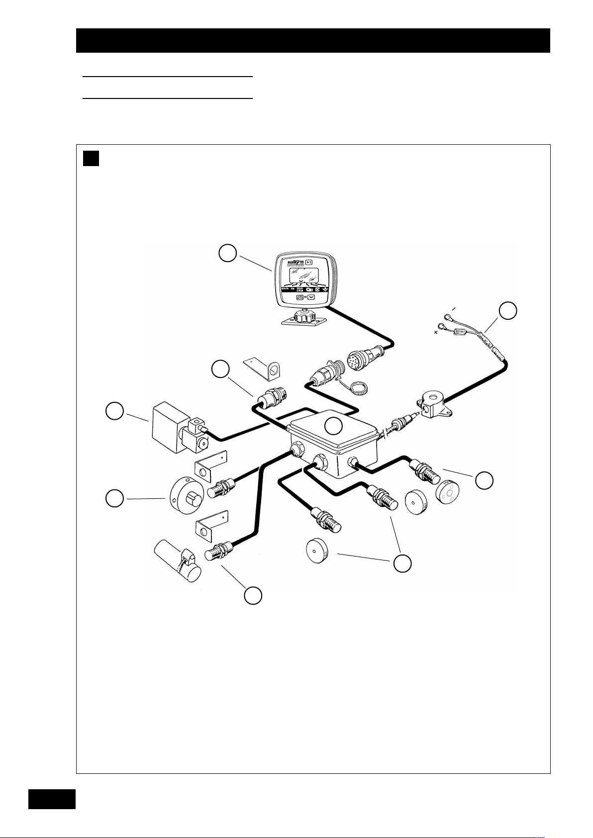
Schématisation du système
A
a)
Branchement :
b)
Connection :
F
- Il est impératif de brancher le boîtier directement sur la
batterie de 12 volts avec le câble de raccordement prévu
à cet effet.
- Lorsque la prise est branchée, le boîtier doit s’allumer
- Le boîtier possède un accumulateur permettant de garder
en mémoire les données programmées.
System diagram
A
a)
Electrical connections :
- The unit must be connected directly to the 12 volt Battery
using the cable provided for this purpose.
- As soon as it is plugged in, the unit should switch on.
- The unit has an internal battery so that the data
programmed into it can be kept in memory.
Boîtier Sulky Tronic
Faisceau d’alimentation avec fusible 3 A
Boîte de connection sur semoir
Capteur turbine (SPI . SPL . Solo).
Capteur de jalonnage (1 ou 2)
Capteur de vitesse / Surface
Capteur de l’arbre de distribution
Electrovanne
Capteur de fin de trémie
b)
Connection :
Sulky Tronic unit
Power leads with 3 A fuse
Seed drill connection unit
Turbine sensor (SPI . SPL . Solo).
Tramlining sensor(s) (1 or 2)
Speed/surface area sensor
Distribution shaft sensor
Solenoid valve
Hopper empty sensor
1
B
G
Systemschaltplan
A
a)
Anschluss
- Das Gerät muß unbedingt direkt auf der 12 Volt Batterie
mit dem dafür vorsehenen Kabel angeschlossen werden.
- Wenn der Stecker angeschlossen ist, muß sich das Gerät
einschalten.
- Das Gerät besitzt einen Speicher zur Aufzeichnung der
programmierten daten.
b)
Verbindung :
Sulky Tronic-Gerät
Versorgungskabelbündel mit Sicherung 3A
Abzweigdose auf Drillmaschine
Turbinen-Sensor (SPI . SPL . Solo).
Markierungs-Sensor (1 oder 2)
Sensor Geschwindigkeit/Fläche
Nockenradwellen-Sensor
Magnetventil
Sensor leerer Saatkasten
D
7
ise en fonctionnement
M
Setting Up
Inbetriebsetzung
B
a)
b)
3
2
4
1
8

ise en fonctionnement
M
Setting Up
Inbetriebsetzung
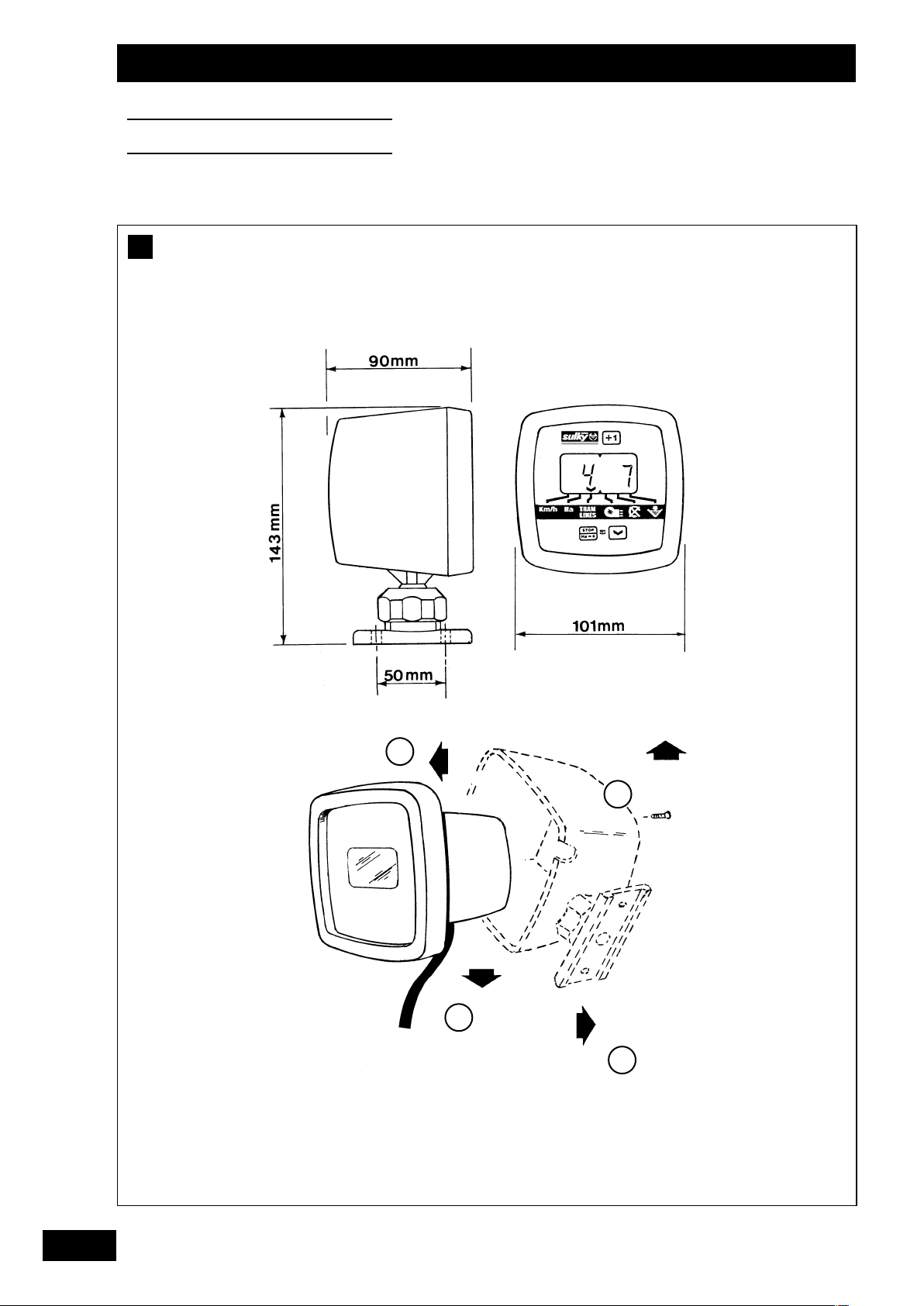
Montage
B
)
a
Encombrement :
- Le boîtier électronique doit être monté de manière à ce
qu’il soit bien visible pour le conducteur.
b)
Fixation :
- En démontant le carter du boîtier, il est possible de le fixer
dans 4 positions par rapport au cadran.
- Fixer le pied du boîtier en perçant à l’emplacement désiré
(2 trous d’entre-axe 50 mm, Ø 5 mm)
F
Assembly
B
a)
Unit dimensions :
- The electronic control unit must be mounted so that it is
clearly visible to the driver.
b)
Mounting :
- By dismantling the control unit casing, the control unit can
be mounted in one of 4 positions relative to the display.
- Attach the foot of the unit by drilling mounting holes in the
location desired : 2 holes, distance between centres 50 mm,
diameter 5 mm.
Montage
B
a)
Gerätabmessungen:
- Das Elektronikgerät muß im Sichtbereich des Fahrers
montiert werden.
B
G
D
b)
Befestigung :
- Durch Abbau des Gerätegehäuses kann dieses in Bezug
auf die Skale in 4 Stellungen befestigt werden.
- Den Ansatz des Gerätes nach Bohren von 2 Löchern mit
einem Durchmesser von 5 mm und einem Achsabstand
von 50 mm an der gewünschten Stelle befestigen.
9
ise en fonctionnement
M
Setting Up
Inbetriebsetzung
C
1
2
3
5
3.1 3.2 3.3 3.4 3.5 3.6
4
10

ise en fonctionnement
M
Setting Up
Inbetriebsetzung
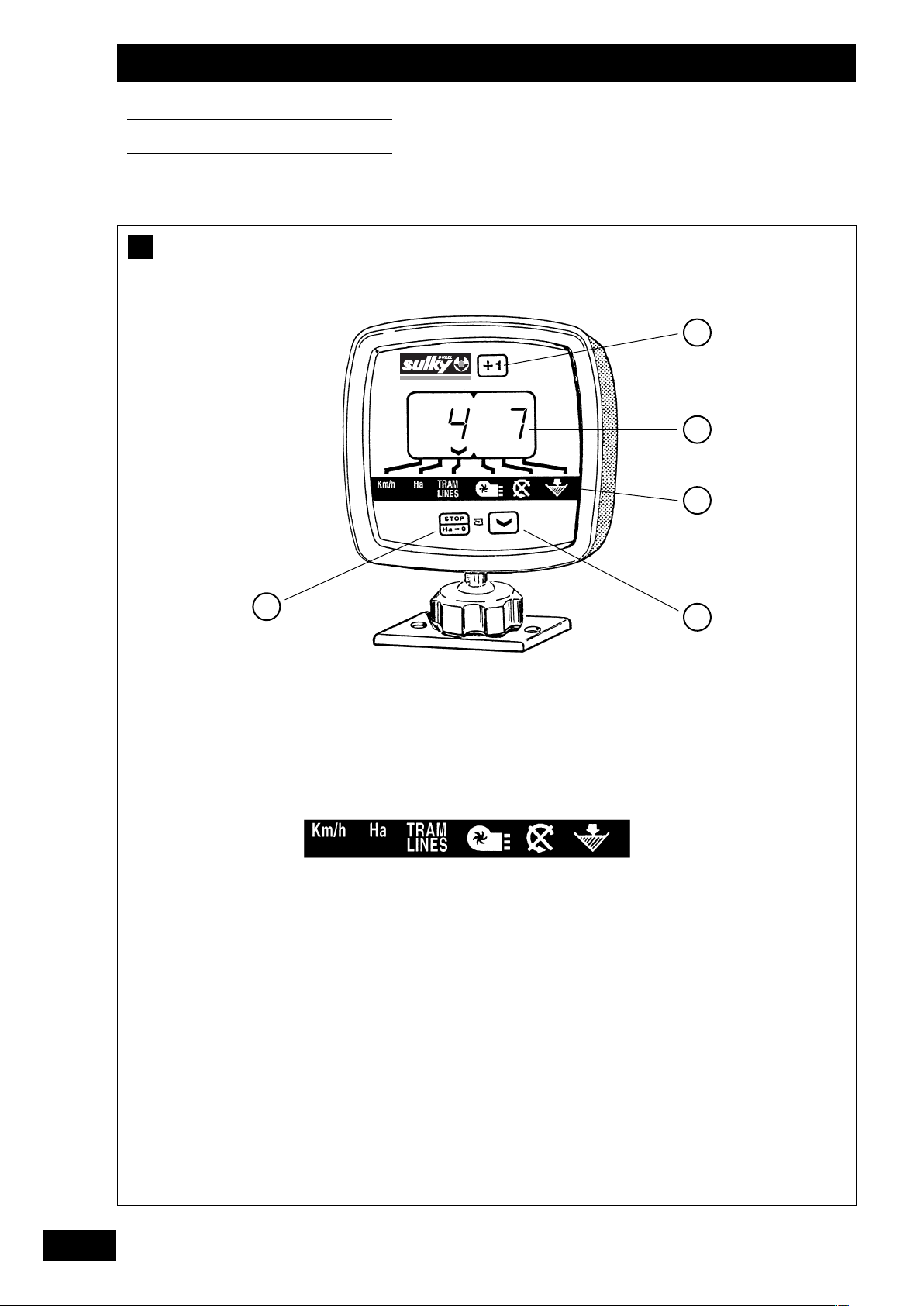
Fonctions
C
a)
Fonctions :
- La fonction principale du boîtier est la fonction
“TRAMLINES”. Au cours du travail le curseur revient sur
celle-ci, après on peut à l’aide de la touche revenir sur
les autres fonctions. Dans le cas d’une anomalie, le curseur
se place automatiquement sur la fonction défectueuse,
accompagné d’un bip sonore.
b)
Informations :
- Avance manuelle TRAMLINES (comptage)
- Sélection surface
- Programmation
- Cadran avec éclairage
^
- Curseur d’indication de fonction sélectionnée
F
- Fonctions
^
3.1 Vitesse d’avancement en lecture directe en Km/h.
3.2 Compteur ha, lecture directe à 2 niveaux.
3.3 Jalonnage, comptage et sélection du passage.
3.4 Vitesse de rotation en lecture directe de la turbine
en Tr/mn (pour SPI)
3.5 Indication de la rotation de l’arbre de distribution.
3.6 Indication de fin de trémie.
- Sélection de la fonction (déplacement curseur)
- Programmation
- Arrêt comptage TRAMLINES
- Remise à zéro des 2 niveaux de compteur d’ha Total1
Total2
Functions
C
a)
Functions:
- The main function of the unit is the TRAMLINES function.
While working, the cursor returns to this function; use
the key to move the cursor on to other functions. In the
event of any anomaly, the cursor automatically positions itself
on the faulty function, accompanied by an audible signal.
b)
Information:
^
- TRAMLINES manual advance (counting)
- Selection of the surface area
- Programming
- Illuminated display
^
- Cursor indicates the function selected
Anschluss
C
a)
Funktionen :
- Die Hauptfunktion des Gerätes ist die des Tramlines.
Im Laufe der Arbeit Kehrt der Cursor zu dieser Funktion
zurück, anschließend kann man mittels der Taste zu den
anderen Funktionen zurückkehren. Im Störungsfall stellt
sich der Cursor mit gleichzeitigem Geraüschsignal
automatisch auf die gestörte Funktion.
b)
Informationen :
^
- Manuelles Tramlines-Fortschalten (Zählung)
- Flächenwahl
- Programmierung
- Skale mit Beleuchtung
^
- Cursor zum Anzeigen der gewählten Funktion
B
G
- Functions
3.1 Direct read-out of speed of advance in Km/h
3.2 Hectare counter, direct two-level read-out
3.3 Marking, counting and selection of run
3.4 Direct read-out of speed of rotation of turbine in
rpm (for SPI)
3.5 Distributor shaft rotation indicator
3.6 Seed box empty indicator
- Select function (move cursor)
- Programming
- Stop TRAMLINES counting
- Reset the 2 levels of the hectare counter Total1
Total2
D
- Funktionen
3.1 Direktablesung der Fahrgeschwindigkeit in Km/h
3.2 Ha-Zähler, Direktablesung mit 2 Anzeigen.
3.3 Fahrgassenmarkierung, Zählung und Wahl der Hinund Rückfahrt.
3.4 Direktablesung der Turbinendrehzahl in U/Min (Für
SPI)
3.5 Anzeige der Verteilerwellendrehung
3.6 Anzeige leerer Kasten
- Funktionswahl (Cursorversellung)
- Programmierung
- Abschaltung Tramlines-Zählung
- Nullstellung der beiden ha-Zähleranzeigen
Gesamtsumme 1 Gesamtsumme 2
11
tilisation
U
Operation
Benutzung
A
PROG
STOP
Ha
0
^
^
0
12
tilisation
U
Operation
Benutzung
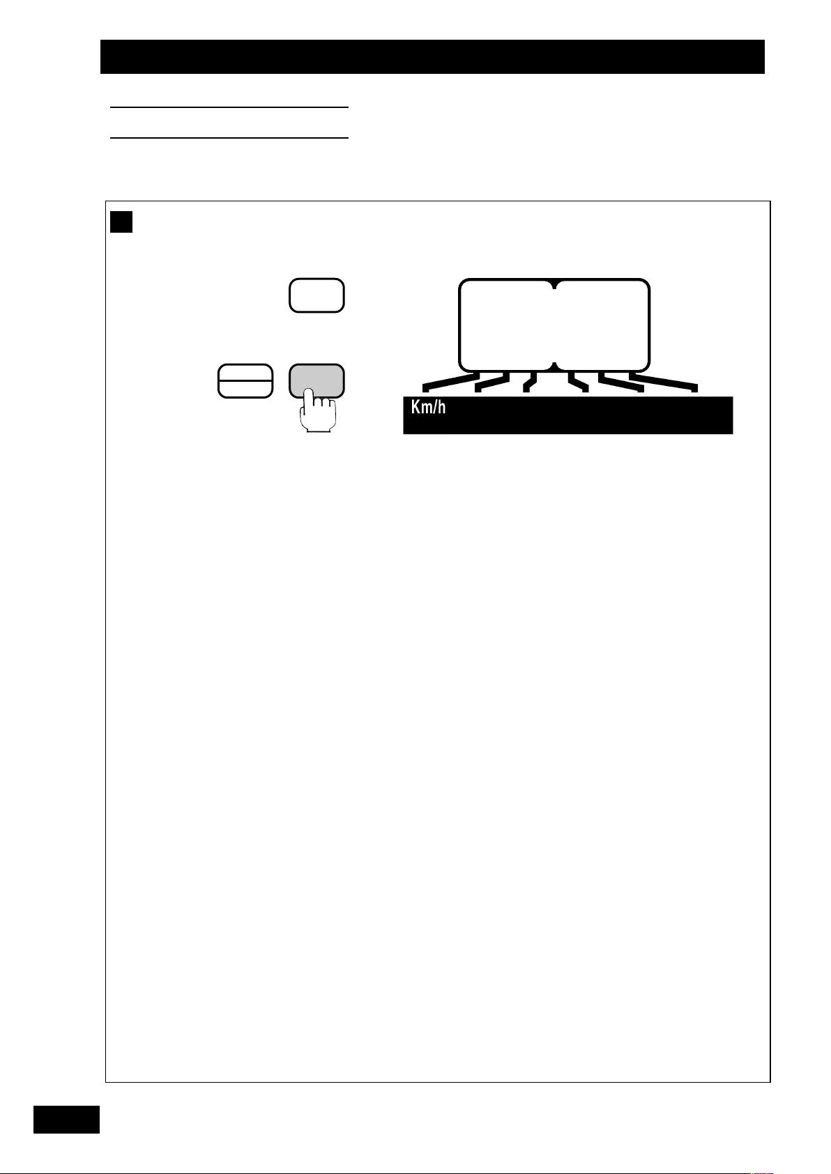
Vitesse d’avancement
A
F
a)
Utilisation :
Appuyer pour amener le curseur sur Km/h.
Au travail la vitesse d’avancement s’affiche.
Le boîtier ne fonctionne que pour une vitesse d’avancement
supérieure à 2 Km/h.
Le boîtier est programmé avec un coefficient de 3.333
permettant une lecture directe de la vitesse.
Si vous observez que la vitesse indiquée n’est pas correcte,
vous pouvez :
- Vérifier que le coefficient est toujours en mémoire
(voir page 15 - b)
- Etalonner à nouveau le boîtier sur une distance de
100 m (voir page 17 - c)
A
Speed of advance
a)
Operation :
Press to move the cursor on to Km/h.
When working, the speed of advance is displayed.
The unit only works for a speed of advance greater than
2 Km/h.
The unit is programmed with a coefficient of 3.333 so that
the speed can be read off directly.
Remarque:
On peut observer une différence de quelques pourcentages
de la valeur Km/h du boîtier par rapport à celle donnée par
le tracteur. L’étalonnage du boîtier sur 100 m est la solution
la plus précise pour obtenir une vitesse d’avancement la
plus proche de la réalité.
Note
:
A difference of a few per cent may be observed between
the k.p.h. indication on the unit and on the tractor.
Calibrating the unit over 100 m is the most accurate
method of obtaining a reading as close as possible to the
actual forward speed.
B
G
2
If you notice that the speed indicated is not correct :
- Check that the coefficient is still stored in memory
(see page 15 - b)
- Recalibrate the unit over a distance of 100 m
(see page 17 - c)
A
Fahreschwindigkeit
a)
Benutzung :
Drücken, um Cursor auf Km/h zu stellen.
Bei der Arbeit wird die Fahrgeschwindigkeit angezeigt.
Das Gerät funktioniert nur bei einer Fahrgeschwindigkeit
von mehr als 2 Km/Stunde.
Das Gerät ist mit einem Koeffizientten von 3.333
programmiert, der eine Direktablesung der
Geschwindigkeit erlaubt.
Sollte die angezeigte Geschwindigkeit nicht korrekt sein,
können Sie :
- Kontrollieren, ob der Koeffizient weiterhin
gespeichert ist (vgl. p 15 - b)
- Das Gerät erneut auf eine Strecke von 100 m eichen
(vgl. p 17 - c)
Anmerkung
Der vom Gehäuse angezeigte Wert km/h kann manchmal
von dem des Schleppers um einige Prozente abweichen.
Mit der Eichung des Gehäuses auf 100 m kann in diesem
Fall eine der Realität entsprechende Fahrgeschwindigkeit
erzielt werden.
:
D
13
tilisation
U
Operation
Benutzung
1
2
STOP
Ha
STOP
Ha
0
0
+1
+1
^
^
^
0.000
^
8
14
3
STOP
Ha
0
+1
^
3.333
^

tilisation
U
Operation
Benutzung
b)
Contôle du coefficient :
F
1)
Sélectionner la fonction Km/h
2)
Appuyer et maintenir : Le coefficient apparaît
- S’il est correct relâcher
- S’il est faux maintenir appuyé pendant
b)
Checking the coefficient :
1)
Select the Km/h function
2)
Press and hold down : The coefficient is displayed
- if correct release
- if incorrect Keep pressed down throughout
toute la programmation
programming
3) Avec l’autre main :
Appuyer pour modifier le chiffre qui clignote.
Relâcher lorsque le chiffre voulu apparaît.
Effectuer la même opération pour les autres chiffres et
l’emplacement du point.
Le coefficient théorique est de “3.333”
3) With your other hand :
Press to modify the figure which is flashing
Release when the required figure appears
Repeat this operation for the other figures and for the
location of the decimal point.
The coefficient should be “3.333”
B
G
b)
Koeffizientenkontrolle :
1)
Die funktion Km/h wählen
2)
Drücken und festhalten : Der koeffizient erscheint
- wenn korrekt loslassen
- wenn falsch während der ganzen program
mierung heruntergedrückt lassen
D
3) Mit der anderen Hand :
Drücken um die blinkende Zahl zu ändern.
Loslassen wenn die gewünschte Zahl erscheint.
Gleicher Vorgang für die anderen Zahlen und die
Punktstellung.
Der Koeffizient muß “3.333” sein.
15

tilisation
U
Operation
Benutzung
1
2
STOP
Ha
STOP
Ha
0
0
+1
+1
^
^
^
3.333
^
0
16
3
STOP
Ha 0
+1
^
AUTO
^

tilisation
U
Operation
Benutzung
c)
Etalonnage sur 100 m :
1)
Placer le semoir au premier jalon
Sélectionner la fonction Km/h
100m
2)
Appuyer et maintenir : Le coefficient apparaît
puis lâcher après l’opération 3
)
3
Avec l’autre main :
Appuyer pour mettre en place la programmation automatique
F
c)
Calibration over 100 metres :
1)
Position the seed drill at the first marking point
Select the Km/h function
100m
2)
Press and hold down : The coefficient is displayed
then Release after operation 3
c)
Eischung auf 100 m :
1)
Drillmaschine auf erste Fahrgassenmarkierung stellen
Die funktion Km/h wählen
3)
With your other hand :
Press to start automatic programming
3)
Mit der anderen Hand :
Drücken, um die automatische Programmierung auszulösen.
B
G
D
100m
2)
Drücken und festhalten : Der koeffizient erscheint
dann nach Vorgang Nr. 3 loslassen
17

tilisation
U
Operation
Benutzung
4
5
STOP
Ha
STOP
Ha
0
0
+1
+1
^
^
0064
^
3.332
^
18

tilisation
U
Operation
Benutzung
4)
Parcourir la distance de 100 m
Le nombre d’impulsion défile.
00m
1
5) A la fin des 100 m :
Appuyer, le nouveau coefficient apparaît.
Le boîtier garde ce coefficient en mémoire et annule le
précédent.
F
Remarque
4)
: la différence entre le coefficient théorique et le
coefficient obtenu à l’essai est en général très faible.
Travel the distance of 100 metres
The number of pulses is displayed.
100m
5) At the end of the 100 metres :
Press STOP, the coefficient is then displayed.
The unit stores this coefficient in memory and cancels
the previous value.
Note: the difference between the theoretical coefficient
and the coefficient obtained through testing is
generally very low.
4)
100 m fahren
Die Impulszahl läuft ab.
B
G
D
100m
5) Am Ende der 100 m :
Drücken, der Koeffizient erscheint.
Das Gerät speichert diesen Koeffizienten und annulliert
den vorausgehenden.
Anmerkung
: die Differenz zwischen dem theoretischen und
dem bei der Abdrehprobe erhaltenen Koeffizienten
ist im allgemeinen sehr klein.
19

tilisation
U
Operation
Benutzung
B
1
2
STOP
Ha
STOP
Ha
0
0
+1
+1
^
^
20.40
^
tot.1
^
20
3
STOP
Ha 0
+1
^
tot.2
^

tilisation
U
Operation
Benutzung
Compteur d’hectare
B
a)
Utilisation :
1)
Sélectionner la fonction ha :
Maximum 9999, lecture en ha et 1/10ème d’ha
Remarque : Dans le cas d’un semis sur une 1/2 largeur le
compteur calcule la surface réellement semée.
2) Appuyer et relâcher Le premier total apparaît
3) Appuyer et relâcher Le deuxième total apparaît
F
B
Hectare counter
a)
Operation :
1)
Select the function (ha) :
Maximum 9999, read-out in hectares and tenths of a hectare
Note : When sowing over a 1/2 width, the counter calculates
the width sown.
2) Press and release The first total is displayed
3) Press and release The second total is displayed
B
Hektarzähler
a)
Benutzung :
1)
Die ha-Funktion wählen :
B
G
D
Maximum 9999, Ablesung in ha und in 1/10 ha
Anmerkung : Bei Aussaat über die halbe Breite zählt das
Zählwerk nur die besäte Fläche.
2) Drücken : Die erste Gesamtsumme erscheint
3) Drücken : Die zweite Gesamtsumme ercheint
21

tilisation
U
Operation
Benutzung
1
2
STOP
Ha
STOP
Ha
0
0
+1
+1
^
^
10.00
^
4.000
^
22
3
STOP
Ha 0
+1
^
4.000
^

tilisation
U
Operation
Benutzung
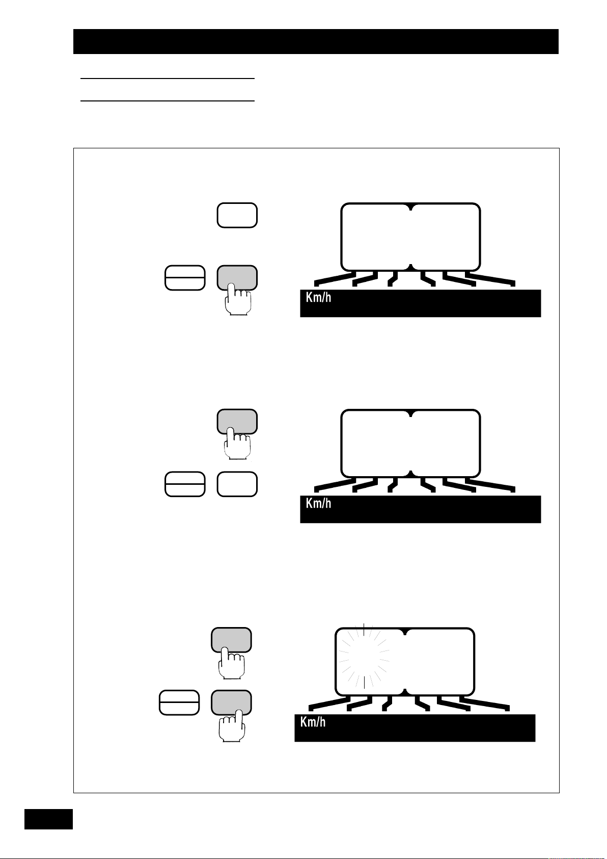
b)
Programmation :
Contrôle de la largeur de travail programmée.
F
3) Avec l’autre main :
Appuyer pour modifier le chiffre qui clignote.
1)
Sélectionner la fonction ha
2) Appuyer et maintenir : La largeur de travail apparaît
- Si elle est correcte relâcher
- Si elle est fausse maintenir appuyé pendant
b)
Programming :
Checking the programmed working width.
1)
Select the hectare function
2)
Press and hold down : The width appears
- if it is correct Release
- if it is incorrect Keep held down throughout
toute la programmation
programming
Relâcher lorsque le chiffre voulu apparaît.
Effectuer la même opération pour les autres chiffres et
l’emplacement du point.
Semoir 3m “3.000”
Semoir 3,5 m “3.500”
Semoir 4 m “4.000”
Semoir 4,5 m “4.500”
Semoir 4,8 m “4.800”
Semoir 5 m “5.000”
Semoir 6 m “6.000”
3) With your other hand :
Press to modify the figure which is flashing
Release when the required figure appears
Repeat this operation for the other figures and for the
location of the decimal point.
3m Seed drill “3.000”
3,5 m Seed drill “3.500”
4 m Seed drill “4.000”
4,5 m Seed drill “4.500”
4,8 m Seed drill “4.800”
5 m Seed drill “5.000”
6 m Seed drill “6.000”
B
G
b)
Programmierung:
Kontrolle der programmierten Arbeitsbreite.
1)
Die ha-Funktion wählen
2)
Drücken und heruntergedrückt halten : Die breite
erscheint
- wenn korrekt loslassen
- wenn falsch während der ganzen program
mierung heruntergedrückt lassen
D
3) Mit der anderen Hand :
Drücken um die blinkende Zahl zu ändern.
Loslassen wenn die gewünschte Zahl erscheint.
Gleicher Vorgang bei den anderen Zahlen und der
Punktstellung.
Drillmaschine 3m “3.000”
Drillmaschine 3,5 m “3.500”
Drillmaschine 4 m “4.000”
Drillmaschine 4,5 m “4.500”
Drillmaschine 4,8 m “4.800”
Drillmaschine 5 m “5.000”
Drillmaschine 6 m “6.000”
23

tilisation
U
Operation
Benutzung
1
2
STOP
Ha
STOP
Ha
0
0
+1
+1
^
^
20.00
tot.2
^
^
24
3
STOP
Ha 0
+1
^
0.000
^

tilisation
U
Operation
Benutzung
C)
Remise à zéro du compteur d’Ha :
1)
Sélectionner la fonction ha
2) Appuyer et sélectionner le total à remettre à zéro
Total 1 ou Total 2 (voir page 21)
Relâcher
3) Appuyer et maintenir pendant plus de 5 secondes
L’effacement de la surface est précédé de 5 bips sonores.
Total 1 et Total 2 vous permettent d’avoir 2 niveaux de
compteur ha (1 journalier et 1 saisonnier par exemple)
F
C)
Resetting the hectare counter :
1)
Select the function (ha)
2) Press to select the total to be reset
Total 1 or Total 2 (see page 21)
Release
3) Press and hold down for over 5 seconds
The unit beeps 5 times before clearing the surface area value
Total 1 and Total 2 enable you to have 2 hectare counter
levels (1 daily total and 1 per season for example)
C)
Nullstellung des ha-Zählers:
1)
Die ha-funktion wählen
2) Drücken, um die auf null zurückzustellende
Summe zu wählen
B
G
D
Gesamtsumme 1 oder Gesamtsumme 2 (Vgl. 21)
Loslassen
3) Drücken und länger als 5 Sekunden
heruntergedrückt halten
Der Löschung der Flächenzahl gehen 5 Geräuschsignale
voraus
Gesamtsumme 1 und Gesamtsumme 2 : erlauben
Ihnen 2 ha - Zählerablesungen (z. B. 1 pro Tag und 1
pro Jahreszeit).
25

tilisation
U
Operation
Benutzung
C
+1
1
STOP
Ha
STOP
Ha
0
0
+1
^
^
2 6
Stop
^
^
26
2
STOP
Ha 0
+1
^
2 6
^

tilisation
U
Operation
Benutzung
Jalonnage (Tramlines)
C
a)
Sélectionner la fonction TRAM LINES
Chiffre de gauche : comptage
Chiffre de droite : chiffre programmé
Le comptage se fait par inversion des traceurs.
Le boîtier informe par un bip sonore le début de débrayage
des distributions.
1)
Arrêt du comptage
Pour inversion des traceurs en milieu de parcelle
Pour non utilisation du jalonnage
Appuyer
Remarque : Ne pas être sur le chiffre de programmation
(le Tramlines fonctionnerait).
2) Reprise du comptage
Appuyer
F
C
Marking Out (Tramlines)
a)
Select the TRAM LINES function
Left hand figure : counting
Right hand figure : programmed figure
Counting takes place by reversal of row markers.
The unit indicates the start of disengagement of the distributors
by means of an audible signal..
C
Fahrgassenmarkierung (Tramlines)
a)
Die TRAMLINES-Funktion wählen
Linke Zahl : Zählung
Rechte Zahl : Programmierte Zahl
Die Zählung erfolgt durch Spurreißerumkehrung.
Das Gehäuse meldet den Beginn der Verteilerauskupplung
durch Geräuschsignal.
1)
Stopping the counting
For reversal of row markers in the middle of the plot of land
For no tramlining.
Press
Note
: Make sure you're not on the program figure
(Tramlines would operate).
2) Restart counting
Press
1)
Abschaltung der Zählung
Zur Spurreißerumkehrung in Parzellenmitte
Für Nichtbenutzung der Fahrgassenmarkierung
Drücken
Anmerkung : Nicht die Programmierzahl wählen (sonst
funktioniert die Fahrgassenmarkierung
(Tramlines).
B
G
D
2) Wiedereinschaltung der Zählung
Drücken
27

tilisation
U
Operation
Benutzung
1
2
STOP
Ha
STOP
Ha
0
0
+1
+1
^
^
2 6
54.06
^
^
28
3
STOP
Ha 0
+1
^
54.08
^

Utilisation
Operation
Benutzung
b)
Programmation :
1)
Sélectionner la fonction TRAM LINE S
2)
Appuyeretmaintenirpendanttoute la programmation
Le chiffre de droite clignote
L’inscription de gauche correspond au mode de tramlines :
AR
Asymétrique (droit) Non utilisé
AL
Asymétrique (gauche)
SY
Symétrique : (Voir p 32 et 33)
3)
Avec l’autre main :
Appuyer pour modifier le chiffre qui clignote.
AR
Si le mode est
pour avoir ensuite le modeAL, puis jusqu’à 12 pour
et vis versa.
, faire défiler les chiffres jusqu’à 12
F
SY
GB
b)
Programming :
1)
Select the TRAMLIN ES function
2)
Press and hold down throughout programming
The right-hand figure flashes
The left-hand indication relates to the tramlines mode:
AR
Asymmetrical (right) Not used
AL
Asymmetrical (left)
SY
Symmetrical : (See p 32 and 33)
3)
With your other hand :
Press to change the figure which is flashing.
AS
If in
display theALmode, then to 12 forSYand vice-
versa.
b)
Programmierung :
1)
Die TR AMLIN ES-Funktion wählen
2)
Drücken und während der ganzen Programmierung
heruntergedrückt lassen
Die rechte Zahl blinkt
Die linke Anzeige entspricht dem Tramlines-Modus:
mode, scroll through the figures as far as 12 to
D
AR
Asymmetrisch (rechts) Nicht benutzt
AL
Asymmetrisch (links)
SY
Symmetrisch : (vgl. S. 32 und 33)
3)
Mit der anderen Hand :
Die blinkende Zahl durch Drücken ändern.
AS
-Funktion die Zahlen bis 12 ablaufen lassen, um
Im
die
AL
-Funktion und bis 12 dieSY-Funktion um
umgekehrt zu erhalten.
29

tilisation
U
Operation
Benutzung
1
2
STOP
Ha
STOP
Ha
0
0
+1
+1
^
^
2 6
5 6
^
^
30

tilisation
U
Operation
Benutzung
F
C)
Avance manuelle du comptage :
• Pour le commencement de la parcelle :
1) Appuyer pour sélectionner la fonction TRAMLINES
• Pour jalonner directement :
2) Appuyer sur +1 pour mettre le chiffre précédent le
chiffre de programmation.
• Agir sur l’hydraulique pour lever le traceur. Le comptage
passe directement au chiffre de programmation et
clignote.
• Baisser l’autre traceur pour agir sur le système hydraulique de
débrayage du semoir.
C)
Manual counting advance
• To begin the plot :
1) Press to select the TRAMLINES function.
• To mark directly :
2) Press +1 to display the number preceding the
programming number.
Remarque :
• L’avance manuelle n’est possible que si il y a un des traceurs
baissé.
• Ne pas oublier d’agir sur l’hydraulique (retirer la pression)
après que les chiffres clignotent pour actionner le système de
débrayage du semoir.
Note
:
• The manual advance function is only possible if one of the
markers is lowered.
• Do not forget to release the hydraulic pressure once the
digits have started flashing in order to activate the seed drill
disengaging system.
B
G
• Raise the marker using the hydraulic control. The
counter changes directly to the programming number
and flashes.
• Lower the other marker to operate the seed drill's hydraulic
disengaging system.
C)
Manuelles Vorstellen der Fahrtenzählung:
• Zum Anfang der Parzelle:
1) Wahl der Tramlines-Funktion durch Drücken
• Zur Direktmarkierung:
2) Auf +1 drücken, um die der Programmierungszahl
vorausgehende Zahl einzustellen.
• Zum Heben des Spuranreißers auf das Hydrauliksystem
einwirken. Die Fahrtenzählung geht direkt auf die
Programmierungszahl über und blinkt.
• Den anderen Spuranreißer senken, um auf das hydraulische
Abschaltsystem der Drillmaschine einzuwirken.
D
Anmerkung :
• Ein manuelles Vorstellen ist nur möglich, wenn einer der
Spuranreißer gesenkt ist.
• Nicht vergessen, nach dem Blinken der Zahlen auf das
Hydrauliksystem einzuwirken (Druck zurücknehmen), um
das Abschaltsystem der Drillmaschine zu betätigen.
31

tilisation
U
Operation
Benutzung
d1)
d2)
3
34512 34512
4 m
3
0 m
1
2
3 5
^
5 5
^
2
3 6
^
1
1
d3)
3456123456123
4 m
2 m
12 m
2
456 123456 123
4 m
12 m
6 6
^
2
4 6
^
.
3
6 6
^
.
1
32

tilisation
U
Operation
Benutzung
) Exemples de jalonnage
d
1)
d
Marquage au centre du semoir (symétrique)
ex : Rampe 20 m semoir 4 m
= 5 Nombre de passage impair
20
4
- Programmer le boîtier sur 5
- Mettre le chiffre de comptage sur 3
- Commencer la parcelle par un passage complet du semoir
A chaque demi-tour, le chiffre de comptage doit avancer
jusqu’au 5. Agir sur l’inversion des traceurs hydrauliques
avant d’engager le 5ème passage. Le chiffre doit ensuite
revenir à 1 pour le passage suivant.
d2) Marquage au centre du semoir (symétrique)
ex: Rampe 24 m semoir 4 m
= 6 Nombre de passage pair
24
4
- Programmer le boîtier sur 6
- Mettre le chiffre de comptage sur 3
-
Commencer la parcelle par un 1/2 semoir (voir manuel du semoir).
A chaque demi-tour, le chiffre de comptage doit avancer jusqu’au 6.
Agir sur l’inversion des traceurs hydrauliques avant d’engager le 6ème
passage. Le chiffre doit ensuite revenir à 1 pour le passage suivant.
d3) Marquage sur un Aller/Retour du semoir (asymétrique)
ex: Rampe 24 m semoir 4 m
= 6 Nombre de passage pair
24
4
Attention au coté du semoir qui jalonne pour débuter la parcelle
- Programmer le boîtier sur 6
- Mettre le chiffre de comptage sur 4. Commencer la parcelle
bordure coté droit.
- A chaque demi-tour, le chiffre de comptage doit avancer
jusqu’au 6. Agir sur l’inversion des traceurs hydrauliques
avant d’engager le 6ème passage. Le chiffre doit ensuite
revenir à 1 et de nouveau jalonner à ce passage.
F
B
G
d) Examples of tramlining
Marking at the centre of the seed drill (symmetrical)
d1)
e.g. 20 m boom, 4 m seed drill
20
= 5 - Odd number of passes
4
- Programme the unit to 5.
- Set the count number to 3.
- Begin the plot with a full seed drill pass. At each field end,
the count number should increase by 1, up to 5. Invert the
hydraulic markers before starting the 5th pass. The number
should return to 1 for the next pass.
d2) Marking at the centre of the seed drill (symmetrical)
e.g. 24 m boom, 4 m seed drill
24 = 6 - Even number of passes
4
d) Markierungsbeispiele
Markierung in Drillmaschinenmitte (symmetrisch)
d1)
B.: Gestänge 20 m Drillmaschine 4 m
20
= 5 ungerade Fahrtenzahl
4
- Gehäuse auf 5 programmiern.
- Zahl der Fahrtenzählung auf 3 stellen.
- Parzelle mit einer kompletten Fahrt der Drillmaschine
beginnen. Bei jedem Wenden muß die Zahl der
Fahrtenzählung bis 5 vorrücken. Vor Beginn der 5. Fahrt auf
die Umkehrung der hydraulischen Spuranreißer einwirken.
Die Zahl muß für die folgende Fahrt auf 1 zurückgehen.
d2) Markierung in Drillmaschinenmitte (symmetrisch)
B.: Gestänge 24 m Drillmaschine 4 m
24
= 6 Gerade Fahrtenzahl
4
- Programme the unit to 6.
- Set the count number to 3.
- Begin the plot with a half seed drill (see drill manual). At each field
end, the count number should increase by 1, up to 6. Invert the
hydraulic markers before starting the 6th pass. The number should
return to 1 for the next pass.
d3) Marking over an Outward and Return pass (asymmetrical)
e.g. 24 m boom, 4 m seed drill
24
= 6 Even number of passes
4
Pay attention to which side of the seed drill is marking when
starting the plot.
- Programme the unit to 6.
- Set the count number to 4. Start the plot on the right-hand
edge.
- At each field end, the count number should increase by 1,
up to 6. Invert the hydraulic markers before starting the 6th
pass. The number should then return to 1 and mark again
on this pass.
- Gehäuse auf 6 programmieren
- Zahl der Fahrtenzählung auf 3 stellen
-
Parzelle mit 1/2 Drillmaschine beginnen (vgl. Drillmaschinen-
Handbuch). Bei jedem Wenden muß die Zahl der Fahrtenzählung bis
6 vorrücken. Vor Beginn der 6. Fahrt auf die Umkehrung der
hydraulischen Spuranreißer einwirken. Die Zahl muß für die folgende
Fahrt auf 1 zurückgehen.
d3) Markierung auf einer Hin- und Rückfahrt (asymmetrisch)
B.: Rampe 24 m Drillmaschine 4 m
= 6 Gerade Fahrtenzahl
24
4
Zum Anfang der Parzelle auf die markierende Drillmaschinenseite
achten.
- Gehäuse auf 6 programmieren
- Zahl der Fahrtenzählung auf 4 stellen. Parzelle am Rand der
rechten Seite beginnen.
- Bei jedem Wenden muß die Zahl der Fahrtenzählung bis 6
vorrücken. Vor Beginn der 6. Fahrt auf die Umkehrung der
hydraulischen Spuranreißer einwirken. Die Zahl muß
anschließend auf 1 zurückgehen und auf dieser Fahrt
erneut markieren.
D
33

tilisation
U
Operation
Benutzung
5 3
m
39 3 2
3,5 21 . 66 34
4 12 32
m
SY AL
12
15 53
18
21 74
24
28
16
20 53
24
28 74
32
36 95
. 44 23
. 66 34
. 88 45
. 88 45
. 44 23
. 66 34
. 88 45
SY AL
SY AL
34
4,5 18
36
4,8 24 53
5 15 32
20
6 12 . 22 12
18 32
24
36
. 44 23
. 88 45
. 44 23
. 44 23
. 66 34

tilisation
U
Operation
Benutzung
e)
Valeurs de programmation :
Y
S
Jalonnage au centre du semoir
AL
Jalonnage sur un aller/retour du semoir
Remarque :
• Dans le cas d’un jalonnage Asymétrique, vérifier qu’il n’y ait
vraiment qu’un coté de la distribution qui se débraye.
• Ne pas oublier de faire correspondre la position des jalonneurs
arrières avec les distributions débrayables.
F
e)
Programming values :
SY
Tramlining at the centre of the seed drill
AL
Tramlining over an Outward & Return pass
Note :
• In the case of Asymmetrical tramlining, check that the
metering devices are only disengaged on one side.
• Do not forget to match the position of the rear markers with the
disengaged metering devices.
e)
Programmierwerte:
SY
Markieren in Drillmaschinenmitte
AL
Markieren auf einer Hin- und Rückfahrt der
Drillmaschine
B
G
D
Anmerkung :
• Bei asymmetrischem Markieren kontrollieren, ob wirklich
nur eine Seite der Verteilung abgeschaltet ist.
• Nicht vergessen, die Stellung der Vorlaufmarkierer den
abgeschalteten Nockenrädern anzupassen.
35

tilisation
U
Operation
Benutzung
D
+1
STOP
Ha
0
^
2800
^
36

tilisation
U
Operation
Benutzung
Vitesse de turbine (semoir SPI)
D
a)
Utilisation :
Sélectionner la vitesse de rotation de la turbine
(lecture Tr/mn)
Cette vitesse doit être comprise entre 2300 et 3800 Tr/mn.
En cas de baisse de régime de la turbine, le curseur se
place automatiquement sur la fonction et est suivi d’un
bip sonore. Le boîtier informe aussi en cas d’un surrégime.
F
D
Turbine Speed
Operation :
a)
Select the turbine rotation speed (read-out in rpm)
This speed must be within the range 2300 to 3800 rpm.
If the turbine speed drops, the cursor automatically
moves to this function, and this is followed by an audible
signal, the unit also indicates when the speed is too
high.
D
Turbinendrehzahl (SPI Drillmaschine)
a)
Benutzung :
Wahl der Turbinendrehzahl (Ablesung U/Min)
(SPI seed drill)
B
G
D
Diese Drehzahl muß zwischen 2300 und 3800 U/Min liegen.
Bei Sinken der Turbinendrehzahl automatische Stellung
des Cursors auf die Funktion gefolgt von einem
Geräuschsignal, das Gehäuse meldet ebenfalls eine zu
große Drehzahl .
37

tilisation
U
Operation
Benutzung
1
2
STOP
Ha
STOP
Ha
0
0
+1
+1
^
^
0
^
2300
^
38
3
STOP
Ha 0
+1
^
2300
^

tilisation
U
Operation
Benutzung
b)
Programmation :
Enregistrement de la valeur minimum de rotation pour
l’alarme
F
1)
Sélectionner la fonction turbine
2) Appuyer et maintenir : La valeur apparaît
- Si elle est correcte relâcher
- Si elle est fausse maintenir appuyé pendant
b)
Programming :
Setting the minimum rotation for the alarm.
1)
Select the turbine function
toute la programmation
2) Press and hold down : the value is displayed
- If it is correct release
- If it is incorrect keep held down throughout
programming
3) Avec l’autre main :
Appuyer pour modifier le chiffre qui clignote.
Relâcher lorsque le chiffre voulu apparaît.
Effectuer la même opération pour les autres chiffres
Valeur : “2300 Tr/mn“
3) With your other hand :
Press to change the figure which is flashing.
Release when the required figure appears.
Repeat this operation for the other figures
Value “2300 rpm“
B
G
b)
Programmierung :
Aufzeichnung des Mindestdrehwerts für den Alarm.
1)
Die Turbinenfunktion wählen
2) Drücken und heruntergedrückt halten: Der Wert
erscheint
- wenn korrekt loslassen
- wenn falsch während der ganzen
Programmierung herunterge
drückt lassen
D
3) Mit der anderen Hand :
Drücken um die blinkende Zahl zu ändern.
Loslassen wenn die gewünschte Zahl erscheint.
Gleicher Vorgang bei den anderen Zahlen.
Wert “2300 Upm“
39

tilisation
U
Operation
Benutzung
E
+1
STOP
Ha
0
^
8
^
40

tilisation
U
Operation
Benutzung
Rotation Distribution
E
• Utilisation :
Sélection de la fonction rotation de l’arbre de distribution
Le chiffre indiqué est le nombre d’impulsion lors de la rotation
de l’arbre.
En cas de non rotation de l’arbre de distribution, le curseur
se place automatiquement sur la fonction, et est suivi d’un
bip sonore.
F
E
Distributor rotation
• Operation :
Selection of the distributor shaft rotation function
The figure shown is the pulse number when the shaft
rotates.
If the distributor shaft is not rotating, the cursor
automatically moves onto this function, and this is followed
by an audible signal.
E
Verteilerdrehung
• Benutzung :
Wahl der Drehfunktion der Verteilerwelle
B
G
D
Die angezeigte Zahl ist die Impulszahl bei der
Wellendrehung.
Bei Nichtdrehung der Verteilerwelle automatische Stellung
auf die Funktion gefolgt von einem Geräuschsignal.
41

tilisation
U
Operation
Benutzung
F
1
2
STOP
Ha
STOP
Ha
0
0
+1
+1
^
^
I
^
I
42
3
STOP
Ha
+1
0
^
0

tilisation
U
Operation
Benutzung
F
Alarme de fin de trémie
F
)
a
Utilisation :
Sert à avertir avant la vidange complète de la trémie.
Régler la hauteur du capteur dans la trémie en fonction
du type de semence.
Lorsqu’il n’y a plus de semence :
- Le curseur vient se placer sur la fonction.
- L’écran affiche ALAr et est suivi d’un bip sonore.
b)
Programmation :
Il est possible de désactiver l’alarme. Ex. Semis
de colza.
F
Seed box empty alarm
a)Operation:
This issues a warning just before the seed box is
completely empty.
Set the height of the sensor in the seed box according to
the type of seed used.
When there is no seed left:
- The cursor moves onto this function.
- The screen displays ALAr and the unit produces an
audible signal.
1)
Sélectionner la fonction trémie.
2)
Appuyer et maintenir: la valeur apparaît
. 1 fonction en marche
1)
. 1 = on
0 fonction à l’arrêt
- Si elle est correcte relâcher.
- Si elle est fausse maintenir appuyé.
3)
Avec l’autre main
Appuyer pour modifier le chiffre.
Select the hopper function.
2)
Press and hold: a digit appears
0 = off
- Release if correct.
- Hold if wrong.
3)
With your other hand, press to change the digit.
B
G
b)
Programming:
The alarm can be deactivated (e.g. for rapeseed).
F
Alarm leerer Kasten
• Benutzung :
Warnt vor kompletter Entleerung des Kastens.
Die Höhe des Sensors im Kasten gemäß Saatgutart
einstellen.
Wenn sich kein Saatgut mehr im Kasten befindet :
- Der Cursor stellt sich auf die Funktion.
- Anzeige ALAr auf Bildschirm, gefolgt von
Geräuschsignal.
b)
Programmierung :
Der Alarm kann abgestellt werden. B. : Rapssaat.
1)
Kastenfunktion wählen.
2)
Drücken und gedrückt halten : der Wert wird
. 1 Funktion bei Betrieb
angezeigt
0 Funktion bei Stillstand
- Wenn korrekt loslassen.
- Wenn falsch heruntergedrückt lassen
3)
Mit der anderen Hand
Drücken, um die Zahl zu ändern.
D
43

nformations
I
Information
Informationen
A
Electrovanne
BRUN
1
2
3
4
5
6
7
8
9
8
FUSIBLE 10 A
BRUN
BLEU
GTDHSN1 N2
+
_
RELAIS
BLEU
E
44
0
7
0 0 0 0 0 3
7 7 7 7 7
0
7

Informations
Information
Informationen
F
Schématisation du circuit
A
0
Bleu
Rouge G Traceur gauche
Noir T Soufflerie
Vert D Traceur droit
Blanc H Vitesse avancement
/ Surface
Violet S Arbre de distribution
Jaune N1
Brun N2 Capteur fin de trémie
Turquoise
Rose E Electrovanne
A B
Circuit diagram
0
Blue
Red G LH marker
Black T Blower
Green D RH marker
White H Forward speed / Area
Purple S Distribution shaft
Yellow N1
Brown N2 Hopper empty sensor
Turquoise
Pink E Solenoid valve
Entretien
B
Boîtier Electronique
a)
• Le boîtier ne nécessite pas d’entretien.
• Il est impératif toutefois de le conserver dans un lieu sec l’hiver.
b) Capteurs
• Les capteurs inductifs ne demandent aucun entretien toutefois
attention aux chocs qui pourraient provoquer le déréglage de
leurs positionnements.
• Bien nettoyer le semoir aprés utilisation pour éviter les dégats
de rongeurs.
Maintenance
aa))
Electronic control unit
• The unit requires no maintenance.
• It must however be kept in a dry place in winter.
b) Sensors
• The inductive sensors require no maintenance ; however,
care should be taken to avoid subjecting them to shock,
since this could upset their positioning.
• Clean the seed drill thoroughly after use to avoid rodent
damage.
GB
Schematische Darstellung der Schaltung
A B
0
Blau
Rot G Linker Spuranreißer
Schwarz T Gebläse
Grün D Rechter Spuranreißer
Weiß H Fahrgeschwindigkeit/
Fläche
Violett S Auslaufwelle
Gelb N1
Braun N2 Sensor leerer Saatkasten
Türkis
Rosa E Magnetventil
Wartung
aa))
Elektronikgerät
• Wartungsfreies Gerät.
• Im Winter unbedingt trocken lagern.
b) Fühler
• Die Induktionsfühler erfordern keine Wartung, sie jedoch
vor Stößen schützen, die sie verstellen könnten.
• Drillmaschine nach Benutzung zum Schutz vor Nagetieren gut
reinigen.
D
3
45

nformations
I
Information
Informationen
Remèdes aux problèmes
C
F
Le boîtier ne s’allume pas
Le boîtier s’allume puis s’éteint
L’information vitesse est incorrecte
Le comptage des hectares est incorrect
Il n’y a plus de comptage automatique pour le
jalonnage (au comptage 2 fois au lieu de 1)
Correcting faults
C
B
The unit does not switch on
The unit switches on, then switches off
The speed information is incorrect
The hectare count is incorrect
The automatic counting for the marking out no longer
works (counting twice instead of once)
PPaannnneess
FFaauulltt
RReemmèèddeess
Vérifier le branchement 12 V continu
Vérifier le fusible 3 A
Vérifier la polarité + / -
Vérifier le coefficient de vitesse
Vérifier le positionnement du capteur sur l’arbre
Vérifier le coefficient de vitesse
Vérifier la largeur de travail dans le programme
Vérifier le positionnement du capteur sur l’arbre
Vérifier le positionnement du capteur au niveau du
mécanisme d’inversion des traceurs.
Pour COMPACT (vérin sorti, la capteur doit se trouver
en face de l’aimant).
Vérifier la fixation des capteurs à l’articulation des
traceurs pour SPI
RReemmeeddyy
Check the connection to the 12 V dc
Check the 3 A fuse
Check the polarity + / -
Check the speed coefficient
Check the positioning of the sensor on the shaft
Check the speed coefficient
Check programmed working width
Check the positioning of the sensor on the shaft
Check the positioning of the sensor at the level of the
row marker reversal mechanism
For COMPACT (with the cylinder out, the sensor
should be opposite the magnet).
Check the mounting of the sensors at the joint of the
tracers for SPI
B
G
D
46
Störungsabhilfen
C
B
Das Gerät leuchtet nicht auf
Das Gerät leuchtet auf und erlischt wieder
Die Geschwindigkeitsanzeige stimmt nicht
Die Hektarzählung stimmt nicht
Keine automatische Zählung mehr für
Fahrgassenmarkierung (bei Zählung 2 Mal anstatt 1)
PPaannnneenn
AAbbhhiillffeenn
Anschluß 12 V Gleistrom kontrollieren
Sicherung 3 A kontrollieren
Polarität + / - kontrollieren
Geschwindigkeitskoeffizienten kontrollieren
Einstellung des Fühlers auf Welle kontrollieren
Geschwindigkeitskoeffizienten kontrollieren
Arbeitsbreite in Programm prüfen
Stellung des Fühlers auf Welle prüfen
Einstellung de s Fühlers auf Höhe des
Spurreißerumkehrmechanismus prüfen.
Für Compact (bei ausgetücktem Zylinder muß der
Fühler dem Magnet gegenüberstehenden).
Die Befestigung der Fühler auf der
Spurreißergelenkverbindung für SPI prüfen.
 Loading...