

Page 1
A LIRE ATTENTIVEMENT AVANT D’UTILISER LE BOITIER
PLEASE READ CAREFULLY BEFORE USING THE CONTROL BOX
VOR GEBRAUCH DES ELEKTRONIKGERÄTS SORGFÄLTIG LESEN
Réf: 400 441-01 - FR-GB-DE /DIS
35221 Châteaubourg Cedex- FRANCE
Tél: 02.99.00.84.84 - Fax: 02.99.62.39.38
Site Internet : www.sulky-burel.com
e-mail : info@sulky-burel.com
Sulky Burel
BP 92111 - rue Fabien Burel
Page 2
Consignes de sécurité
Safety instructions
Sicherheitsvorschriften
• Respecter les instructions de cette notice.
• Respecter les instructions du manuel d’utilisation du X correspondant.
• Ne jamais quitter le poste de conduite lorsque le tracteur est en marche.
• Réaliser les réglages du STOP & GO tracteur à l’arrêt.
• Assurez-vous qu’il n’y ait personne autour de la machine avant d’effectuer l’étalonnage du STOP & GO .
FR
Risque d’accident Risque d’endommager
la machine
• Ces symboles sont utilisés dans cette notice chaque fois que des recommandations concernent votre
sécurité, celle d’autrui ou le bon fonctionnement de la machine.
• Transmettez impérativement ces recommandations à tout utilisateur de la machine.
• Follow the instructions contained in this manual.
• Follow the X User Manual recommendations.
• Never leave the driver’s position whilst the tractor is running.
• Carry out STOP & GO adjustments with the tractor stopped.
• Make sure no one is near the machine before calibrating the STOP & GO unit.
Risk of accident Risk of damage
to the machine
• These symbols are used in these instructions every time recommendations are provided concerning your
safety, the safety of others or the correct operation of the machine.
• These recommendations must be given to all users of the machine.
Faciliter le travail
Operating tip
Ne pas jeter le boîtier
Do not discard the unit
GB
• Die Anweisungen dieser Anleitung einhalten.
• Die Anweisungen des Benutzerhandbuchs des entsprechenden X einhalten.
• Den Führerstand niemals bei laufendem Schleppermotor verlassen.
• Einstellungen des STOP & GO bei ausgestelltem Schlepper vornehmen.
• Darauf achten, dass sich beim Kalibrieren des STOP & GO niemand im Maschinenbereich aufhält.
Unfallgefahr Gefahr, die Maschine zu
beschädigen
• Diese Symbole werden in dieser Anleitung jedes Mal dann benutzt, wenn Empfehlungen für Ihre und
anderer Personen Sicherheit oder den einwandfreien Betrieb der Maschine gegeben werden.
• Es ist unerlässlich, diese Empfehlungen an alle Benutzer der Maschine weiterzugeben.
Arbeitserleichterung
Elektronikgerät nicht im
Müll entsorgen
2
DE
Page 3
SOMMAIRE
Français
Pages
6-7 • A Présentation du système
Pages
8-9
10-11
Pages
12-15
16-17
PRESENTATION
MISE EN ROUTE
• A Utilisation
• B Câblage du système
REGLAGES
• A Réglages
• B Mes réglages
1
1
1
2
1
3
Pages
18-21
20-23
Pages
24-25
24-27
29
FONCTIONNEMENT
• A Mode automatique
• B Mode manuel
ENTRETIEN
• A Maintenance
• B Diagnostique
• C Pannes - remèdes
Lire attentivement la notice avant l’utilisation. Comprendre son
boîtier électronique c’est mieux l’utiliser. En français suivre le symbole.
1
4
1
5
FR
3
Page 4
English
CONTENTS
Pages
6-7 • A Description of the system
Pages
8-9
10-11
Pages
12-15
16-17
PRESENTATION
START-UP
• A Use
• B System wiring
SETTINGS
• A Settings
• B My settings
Pages
18-21
20-23
Pages
24-25
24-27
29
OPERATION
• A Automatic mode
• B Manual mode
MAINTENANCE
• A Maintenance
• B Diagnostics
• C Problems - Solutions
Read the operator's manual carefully before use. Understanding your electronic unit
will help you make better use of it. English instructions: follow this
symbol.
GB
4
Page 5
INHALTSVERZEICHNIS
Deutsch
Seite
6-7 • A Präsentation des Systems
Seite
8-9
10-11
Seite
12-15
16-17
BESCHREIBUNG
INBETRIEBSETZUNG
• A Benutzung
• B Verkabelung des Systems
EINSTELLUNGEN
• A Einstellungen
• B Meine Einstellungen
1
1
1
2
1
3
Seite
18-21
20-23
Seite
24-25
24-27
29
BETRIEBSARTEN
• A Automatikbetrieb
• B Handbetrieb
WARTUNG
• A Wartung
• B Diagnose
• C Störungen - Störungsbeseitigung
Anleitung vor Benutzung sorgfältig durchlesen. Das Elektronikgerät richtig zu
verstehen, heißt, es besser (aus)nutzen zu können. Die deutsche Fassung ist
mit gekennzeichnet.
1
4
1
5
DE
55
Page 6
Présentation / Presentation / Beschreibung
A
Le système Stop & Go est
un module autonome.
SULKY n’est donc en
aucun cas responsable
des divers problèmes
pouvants provenir du
système de barre de
guidage ainsi que de sa
coupure de tronçons.
6
6
The Stop & Go system is
an autonomous module.
SULKY can therefore not
be held responsible under
any circumstances for
problems that may
originate from the lightbar
guidance or boom section
control systems.
Das Stop & Go System ist
ein unabhängiges Modul
SULKY ist demnach in
keiner Weise für die
verschiedenen Probleme
verantwortlich, die sich
aus der Spurführung und
der dazugehörigen
Teilbreitenschaltung
ergeben könnten.
Page 7
Présentation / Presentation / Beschreibung
FR
Optimisation des épandages d’engrais en
fourrières et bordure de parcelle
A
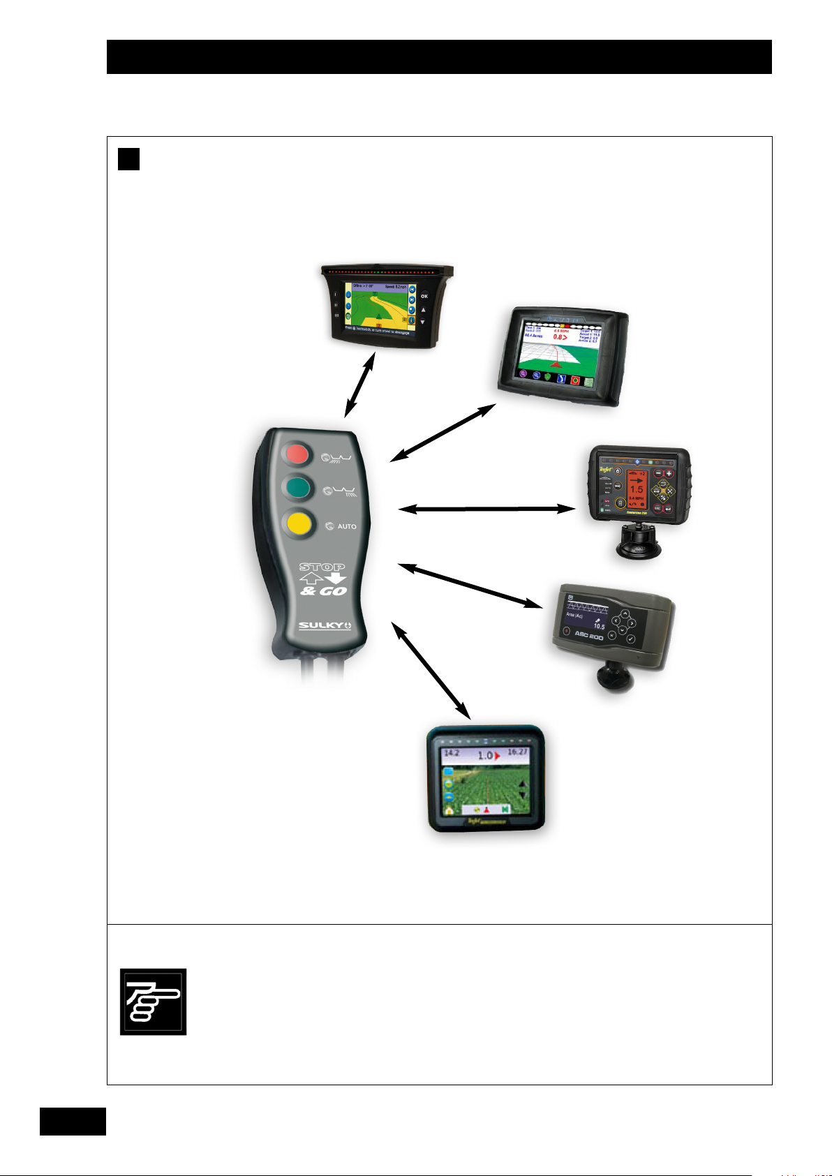
Présentation du système
• Le Stop & Go est un système capable de récupérer
les données provenant d’une barre de guidage et/ou
sa coupure de tronçons afin d’éviter les surdosages
et sous-dosages en fourrières et en bordure de
parcelle.
Le produit est compatible avec tous les épandeurs X
de la gamme SULKY.
Les barres de guidage et coupures de tronçons sont
à la base des produits destinés à la pulvérisation de
produits phyto-sanitaires.
Optimising fertilizer spreading in headlands and
field borders.
Description of the system
A
• The Stop & Go system is able to retrieve the data
from a lightbar and/or its boom section control system
in order to prevent over- and under-application in
headlands and field borders.
The product is compatible with all the X spreaders in
the SULKY range.
Lightbars and boom control systems are used for
controlling pesticide sprayers.
Ils permettent de guider l’utilisateur, ainsi que de
couper automatiquement chaque tronçon de la
machine afin de ne pulvériser qu’une seule fois en
tout point.
Le Stop & Go se sert donc des données sortant du
module de gestion des tronçons d’un pulvérisateur.
Pour cela, il suffit de configurer, au sein de la barre
de guidage, 2 tronçons à utiliser
A
(voir chapitre - Réglages ).
Chaque tronçon correspondra à un disque du
distributeur d’engrais.
Les 2 fils correspondants, sortants de la gestion des
tronçons, doivent être reliés au Stop & Go par une
connectique qui est fournie.
They provide guidance for the user as well as
automatically shutting off boom sections to ensure that
each part of the field is sprayed only once.
The Stop & Go unit is therefore able to use the data
provided by the sprayer’s boom section control module.
All you need to do to make this possible is configure 2
boom sections to be used within the lightbar
(see section - Settings).
Each boom section will correspond to a fertilizer
spreader disk.
The 2 corresponding wires that come out of the boom
section control system should be connected to the Stop
& Go using the connector supplied.
3
A
3
1
1
GB
Optimierung der Düngerstreuung im Vorgewende
und an Feldrändern
A
Präsentation des Systems
• Das Stop & Go ist ein System zur Auswertung von
Daten aus einem Spurführungs-Modul und/ oder
dazugehöriger Teilbreitenschaltung, um Unter- oder
Überdüngung in den Vorgewenden und am Feldrand
zu verhindern.
Das Produkt ist mit allen SULKY-Düngerstreuern der
X-Reihe kompatibel.
Spurführungen und Teilbreitenschaltungen sind
grundlegend für die Produkte, die
Pflanzenschutzmittel spritzen sollen.
Sie führen den Bediener und schalten automatisch
Teilbreiten der Maschine ab, um an jedem Punkt nur
einmal zu spritzen.
Das Stop & Go übernimmt also die Daten aus dem
Teilbreitenmanager einer Spritze.
Dazu müssen bei der Spurführung nur die 2 Teilbreiten
konfiguriert werden, die benutzt werden sollen.
(Siehe Kapitel - Einstellungen).
Jede Teilbreite entspricht einer Scheibe des
Düngerstreuers.
Die beiden dazugehörigen Kabel des
Teilbreitenmanager-Geräts müssen über mitgelieferte
Anschlussstecker an das Stop & Go angeschlossen
werden.
A
3
DE
7
7
Page 8
Mise en route / Start-up / Inbetriebsetzung
A
1
1
2
2
3
3
5
5
4
4
5
5
8
8
Page 9
Mise en route / Start-up / Inbetriebsetzung
A
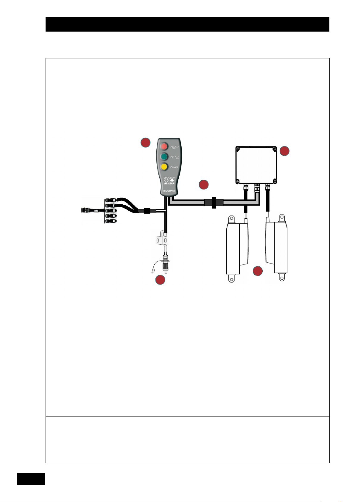
Utilisation
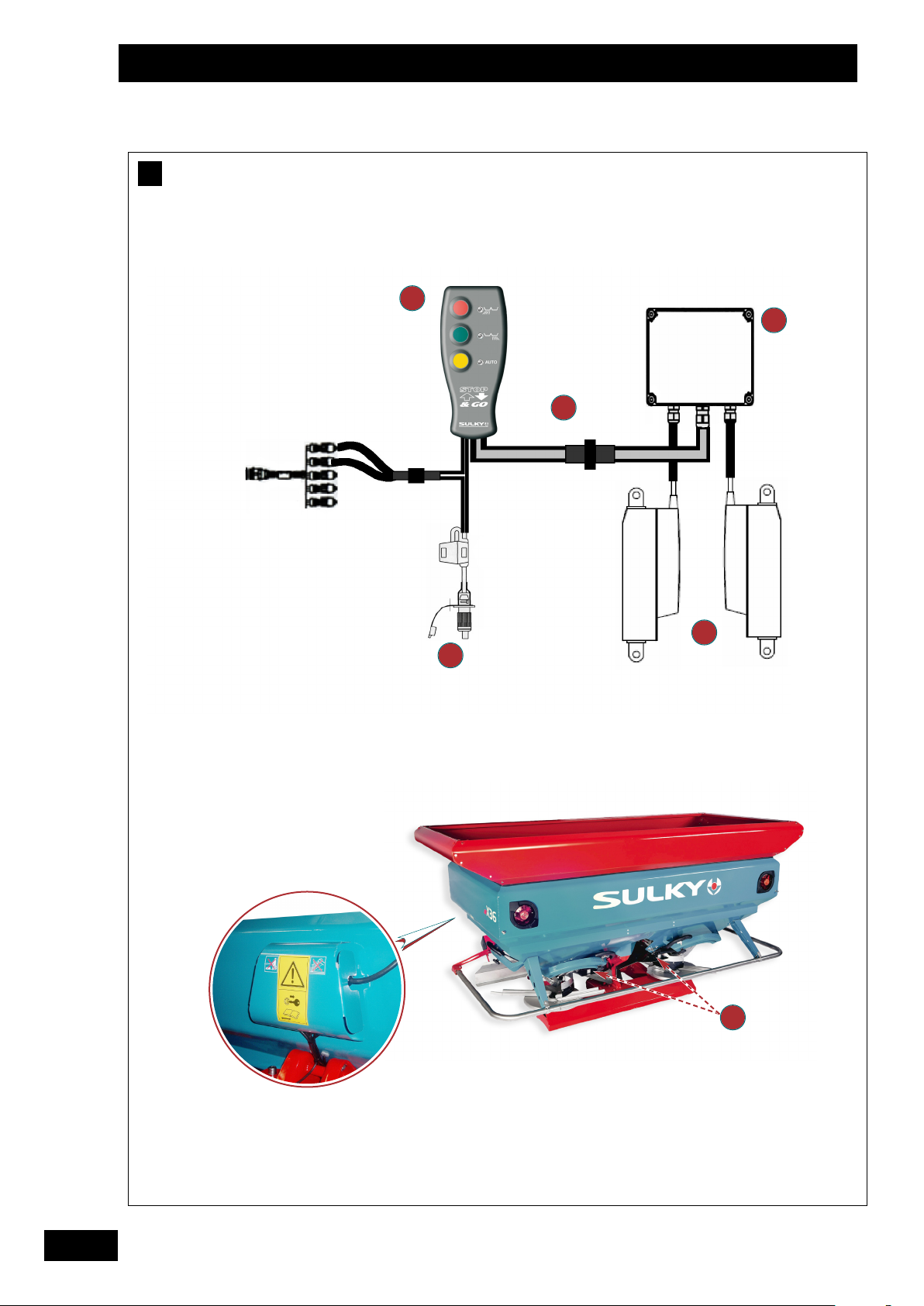
1
1
-
Au moment de la livraison, vérifier que le
système vous est livré complet.
➩ Interupteur de commande ,manuelle ou auto
et trappe droite et trappe gauche.
FR
La commande contient un boîtier de connexion,
une commande manuelle, deux vérins électriques,
deux supports de positionnement des vérins,
ainsi que des connectiques.
• En cas de doute ou de litige, adressez-vous à votre
revendeur.
Use
A
- Check that your equipment is complete on delivery.
The control unit contains a connector box, a manual
controller, two electrical cylinders, two cylinder
positioning supports and the connectors.
• If there is any doubt or dispute, please contact your
dealer.
2
2
➩ Connecteur 6 broches.
3
3
➩ Boîte de connection.
4
4
➩ Alimentation cobo 12 volts .
5
5
➩ Vérins électriques.
1
1
➩ Control, manual or automatic switch and right and
left-hand shutters.
2
2
➩ 6-pin connector.
3
3
➩ Connection box.
4
4
➩ Cobo 12 volt power supply.
5
5
➩ Electrical cylinders.
1
2
GB
Benutzung
A
- Bei Anlieferung prüfen, ob das gelieferte System
vollständig ist.
Die Steuerung besteht aus einem Anschlussgerät,
einer Steuerung für Handbetrieb, zwei elektrischen
Auslösern, zwei Haltern für die Positionierung der
Auslöser sowie Anschlusskabeln und -steckern.
• Im Zweifelsfall oder Schadenfall Ihren Fachhändler
informieren.
1
1
➩ Bedienungsschalter, Hand- oder Automatikbetrieb
und rechter und linker Streuschieber.
2
2
➩ 6-Stifte-Stecker.
3
3
➩ Anschlussgerät.
4
4
➩ Stromversorgung 12 Volt Cobo-Stecker.
5
5
➩ Elektrische Auslöser.
DE
9
9
Page 10

Mise en route / Start-up / Inbetriebsetzung
B
1
1
3
3
2
2
5
5
4
4
10
10
Page 11
Mise en route / Start-up / Inbetriebsetzung
-
B
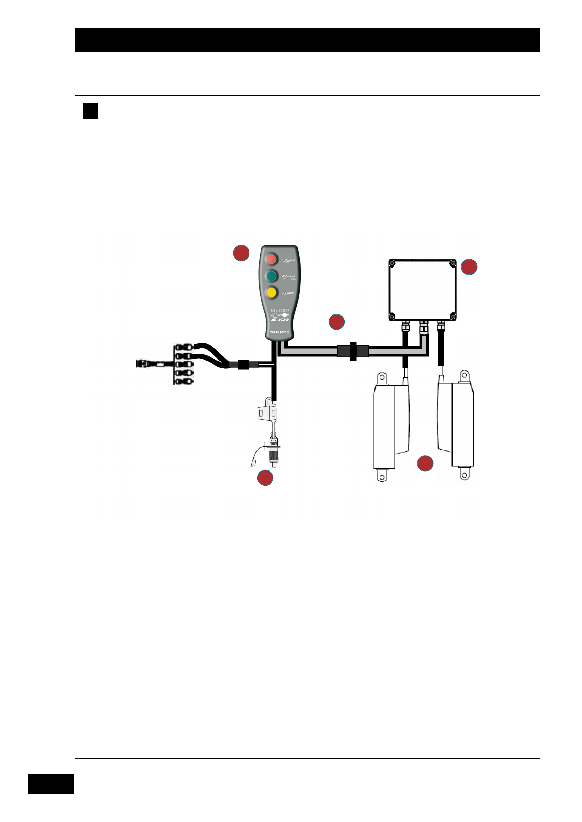
Câblage du système
Le module Stop & Go, protégé par un fusible de 7,5
ampères, nécessite sa propre alimentation par prise
cobo.
Le système de coupure de tronçons peut soit être
alimenté en branchant les deux systèmes sur la
même prise cobo, soit en utilisant un raccord cobo
en « Y » (une prise mâle, deux prises femelles), ou
alors en utilisant une deuxième prise cobo du
tracteur.
Le système Stop & Go utilise des vérins électriques
qui agissent directement sur les trappes de
l’épandeur.
Ils sont spécialement développés pour garder une
vitesse d’ouverture et de fermeture rapide.
ROCÉDURE DE CÂBLAGE :
P
-
Connecter le connecteur 6 broches reliant le
boîtier Stop & Go au boîtier de connexion.
Brancher les 2 fils appropriés du module de
coupure de tronçons au connecteur 2 broches.
- Alimenter le système par la prise cobo.
Le module Stop & Go peut fonctionner sans que le
distributeur d’engrais soit équipé de la console
VISION-X.
Par contre quand on utilise le DPB ou le WPB, il est
possible de visualiser sur la console VISION X l’état
des trappes (ouvertes ou fermées )
1
1
➩ Interupteur de commande ,manuelle ou auto
et trappe droite et trappe gauche
2
2
➩ Connecteur 6 broches
3
3
➩ Boîte de connection
4
4
➩ Alimentation cobo 12 volts
5
5
➩ Vérins électriques
FR
1
2
GB
System wiring
B
The Stop & Go module, which is protected by a 7.5
amp fuse, requires its own power supply, which is
provided via a cobo plug.
The boom section control system can either be
powered by connecting the two systems to the same
cobo plug, or by using a “Y” shaped cobo fitting (one
male plug, two female sockets), or alternatively by
using a second cobo plug from the tractor.
The Stop & Go system uses electrical cylinders that
act directly on the spreader shutters.
They have been specially designed to ensure a rapid
opening and closing speed.
W
IRING PROCEDURE:
- Connect the 6-pin connector that joins the Stop &
Go unit to the connection box.
Verkabelung des Systems
B
Das Stop & Go Modul, gesichert durch eine 7,5
Ampere-Sicherung, braucht eine eigene
Stromversorgung über Cobo-Stecker.
Das Teilbreitenschaltungs-System kann entweder
durch Anschließen beider Systeme an den gleichen
Cobo-Stecker, oder mit Y-Cobo-Anschluss (1 Stiftund 2 Buchsenkontakte) oder über einen zweiten
Cobo-Stecker des Schleppers mit Strom versorgt
werden.
Das Stop & Go System verwendet elektrische
Auslöser, die direkt auf die Streuschieber des
Düngerstreuers einwirken.
Diese wurden eigens dazu entwickelt, um eine
schnelle Öffnungs- und Schließgeschwindigkeit zu
erhalten.
V
ERKABELUNGS-VERFAHREN:
- Stop & Go Gerät mit dem 6-Stifte-Stecker an das
Anschlussgerät anschließen.
- Connect the 2 relevant wires from the boom
section control module to the 2-pin connector.
- Plug the system into the power supply via the cobo
plug.
The Stop & Go unit is able to function without the
fertilizer spreader being fitted with a VISION X console.
Conversely, with the DPB or WPB, it is possible to see
the position of the shutters (open or closed) on the
VISION X console.
1
1
➩
Control, manual or automatic switch and right
and left-hand shutters
2
2
➩
6-pin connector
3
3
➩
Connection box
4
4
➩
Cobo 12 volt power supply
5
5
➩
Electrical cylinders
- Die beiden vorgesehenen Kabel des
Teilbreitenschaltungs-Moduls an den 2-StifteStecker anschließen.
- Das System über den Cobo-Stecker an die
Stromversorgung anschließen.
Das Stop & Go Modul kann funktionieren, auch wenn
der Düngerstreuer nicht mit der VISION-X Konsole
ausgestattet ist.
Bei DPB- oder WPB-Betrieb ist es möglich, über die
VISION X Konsole den Zustand der Schieber (offen
oder geschlossen) zu visualisieren.
1
1
➩
Bedienungsschalter, Hand- oder
Automatikbetrieb und rechter und linker
Streuschieber.
2
2
➩
6-Stifte-Stecker.
3
3
➩
Anschlussgerät.
4
4
➩
Stromversorgung 12 Volt Cobo-Stecker.
5
5
➩
Elektrische Auslöser.
DE
11
11
Page 12

Réglages / Settings / Einstellungen
A
12
12
Page 13

Réglages / Settings / Einstellungen
FR
A
Reglages
Au sein de la barre de guidage doit être définie une
série de paramètres permettant à la barre de
guidage de fonctionner en adéquation avec le Stop
& Go ainsi que la réalité de l’épandage centrifuge.
- Paramétrer au préalable toutes les distances
relatives au positionnement de l’antenne GPS
sur le toit du tracteur.
- Toujours positionner l’antenne à la même
distance de l’épandeur si changement de
tracteur (voir distance X1 et Y1 sur le schéma
de paramétrage des distances ci-contre).
- Définir une machine comprenant 2 tronçons.
- S’assurer de bien paramétrer l’utilisation des
tronçons qui ont été branchés.
(de préférence le numéro 1 et 2).
Settings
A
A series of parameters needs to be defined within the
lightbar to enable it to operate in tune with both the
Stop & Go unit and the reality of the centrifugal
fertilizer spreading.
Le taux de recouvrement indique à quel moment le
système va arrêter d’épandre lorsqu’il rencontre une
zone déjà épandue.
A noter que plus cette valeur est élevée, plus le
risque de manque au cours de l’épandage diminue.
A l’inverse, une faible valeur contribue à limiter les
surdosages dans la parcelle.
Suivant le taux de recouvrement utilisé, le type de
système de guidage et la coupure de tronçons en
votre possession, il peut être normal de retrouver
sur l’affichage du champ de petites zones blanches,
correspondant à un bref arrêt de l’épandage (cas
récurrent des pointes dans le champ).
Cependant, de part le fonctionnement par multirecouvrement d’un épandeur d’engrais Sulky, ces
zones s’avèrent en fait posséder une densité proche
de la dose moyenne d’engrais à apporter.
The overlap rate indicates the point when the system
will stop spreading when it encounters an area where
fertilizer has already been spread.
Note that the higher this value, the lower the risk of
gaps in the coverage.
GB
1
- First set all the distances relating to the positioning
of the GPS antenna on the tractor roof.
- Always position the antenna the same distance
from the spreader if you change your tractor (see
distance X1 and Y1 on the diagram opposite).
-
Specify a machine comprising 2 boom sections.
Make sure that you programme the unit to use
the sections that have been connected
(preferably numbers 1 and 2).
Einstellungen
A
An der Spurführung müssen bestimmte Parameter
definiert werden, damit die Spurführung mit dem Stop
& Go und real mit der Zentrifugalstreuung abgestimmt
wird.
- Vorher alle Abstände gegenüber der GPS-Antenne
auf dem Dach parametrieren.
- Bei Schlepperwechsel Antenne stets im gleichen
Abstand zum Düngerstreuer positionieren (siehe
Abstand X1 und Y1 auf dem
Parametrierungsschema gegenüber).
- Eine Maschine mit 2 Teilbreiten festlegen.
Sich vergewissern, dass die Verwendung der
angeschlossenen Teilbreiten richtig parametriert
ist. (vorzugsweise Nummer 1 und 2).
Conversely, a low value contributes to limiting overapplication in the field.
Depending on the overlap rate used, the type of
guidance system and the boom section control system
in your possession, it may be normal to see small white
areas on the field display that correspond to where
spreading stopped (recurring small areas in the field).
However, because of the way in which a Sulky fertilizer
spreader functions by multi-overlap, these areas may in
fact prove to have a density close to the average
application rate.
Die Überlappungsrate zeigt an, wann das System die
Streuung abschaltet, wenn es auf einen bereits
bestreuten Bereich trifft.
Je höher dieser Wert, je geringer das Risiko der
Unterversorgung mit Dünger.
Im Gegensatz dazu trägt ein geringer Wert zur
Begrenzung der Überdüngung in der Parzelle bei.
Je nach eingestelltem Überlappungsgrad, verwendeter
Spurführung und Teilbreitenschaltung kann es normal
sein, auf der Anzeige der Ausbringungskarte der
Parzelle kleine weiße Bereiche zu finden, dies
entspricht einer kurzen Abschaltung der Ausbringung
(vielfache Punkte im Feld).
Wegen der Mehrfachüberlappungstechnik eines SulkyDüngerstreuers erweist sich jedoch, dass diese
Bereiche eine der gewünschten mittleren Düngerdichte
entsprechende Düngerversorgung aufweisen.
3
DE
13
13
Page 14

Réglages / Settings / Einstellungen
A
12
? 36
28
15 18 21 24 28 24 28 32 36 32 36 40 44
-
Y2 (m)
LR (m)
LG (m)
X2 (m)
X3 (m)
%
Tps (s) O
Tps (s) C
7,5 -9 -10 -12 -14 -12 -14 -15 -15 -16 -17 -16,5 -16,5
7,5 9 10,5 12 14 12 14 16 18 16 18 20 22
7,5 9 10,5 12 14 12 14 16 18 16 18 20 22
3,25 4,5 5,25 6 7 6 7 8 9 8 9 10 11
-3,25 -4,5 -5,25 -6 -7 -6 -7 -8 -9 -8 -9 -10 -11
50 50 60 70 80 60 60 70 80 60 70 70 80
11111 1 11 1 1111
2,5 2,5 2,5 3 3 3 3 3 3 3 3 3 3
24
GPS
32
44
Y1
Y2
X3
Centre de l’épandeur
Centre of the spreader
Mittelpunkt des Schleppers
X1
X2
14
Page 15

Réglages / Settings / Einstellungen
FR
Les valeurs de recouvrement du tableau sont une
A
moyenne optimisée pour différents engrais.
Toutefois, les engrais tels que le chlorure de potassium et
l’urée nécessitent de remonter le taux de recouvrement de 10
pour-cent supplémentaires.
Libre à l’utilisateur d’ajuster les valeurs, selon son jugé.
Le tableau ci-contre présente les différents
paramètres relatifs aux deux tronçons.
Ces paramètres sont à programmer dans le système qui
gère les tronçons et/ou la barre de guidage.
Les valeurs indiquées prennent en compte le type de
distributeur d’engrais, ainsi que la largeur de travail
utilisée.
12
28
Jeux de pales présents sur la machine
Largeur de travail ( épandage ) en mètre
Y2 (m)Distance entre les disques d’épandage et le
point milieu de la nappe d’engrais
pourcentage
LR (m)Largeur de travail ( épandage ) située à droite
The overlap values in the table are an optimised
A
average for different fertilizers.
Nevertheless, for fertilizers such as potassium
chloride and urea the overlap rate should be
increased by a further 10 percent.
It is up to the user to adjust the values according to
his judgement.
The table opposite shows the different parameters that
relate to the two boom sections.
These parameters must be entered into the boom
section control system and/or the lightbar.
The values indicated take into account the type of
fertilizer spreader as well as the working width used.
12
Y2 (m)
Set of vanes on the machine
28
Working width (spreading) in metres
Distance between the spreading disks and
the centre point of the fertilizer distribution
area
LG (m)
X 2 (m)
Largeur de travail ( épandage ) située à gauche
distance pour la demi-largeur de travail située à
droite
X3 (m)
distance pour la demi-largeur de travail située à
gauche
%
Taux de recouvrement conseillé en pourcentage
Tps (s) OAnticipation du temps pour gérer l’ouverture des
trappes ,exprimé en seconde
Tps (s) CAnticipation du temps pour gérer la fermeture
des trappes ,exprimé en seconde
R
EMARQUES
: Les possibilités pour programmer les
paramètres correspondant à la nappe d’épandage et à la
position de l’antenne sont plus ou moins limités suivant la
marque et ou le modèle du système de gestion des
coupures et /ou de la barre de guidage . Il faut
impérativement consulter les notices d’utilisation
correspondantes ,afin de connaitre précisement les limites
A
TTENTION
: une erreur de paramétrage peut entraîner des
zones de surdosage ou de sous-dosage ,dans ce cas
Sulky ne pourra pas être tenu pour responsable .
RW (m)
Working width (spreading) on the right
hand side
LW ( m)
Working width (spreading) on the left
hand side
X2 (m)
Half working width distance on the right
hand side
X3 (m)
Half working width distance on the left
hand side
%
T (s) O
Recommended percentage overlap rate
Expected time taken to control the
opening of the shutters, in seconds
T (s) C
Expected time taken to control the
closing of the shutters, in seconds
The possibilities for programming the parameters
NB:
corresponding to the spreading area and the antenna
position are limited more or less depending on the
brand and / or model of the boom section control
system and / or the lightbar. It is essential to read the
relevant instruction manuals in order to establish the
exact limits.
OTE ! If you make a mistake when setting the
N
parameters, this may result in either over- or underapplication of fertilizer. Sulky will not accept any liability
in this eventuality.
GB
1
3
DE
Die Überlappungswerte der Tabelle entsprechen
A
einem optimierten Mittelwert für verschiedene
Dünger.
Dünger wie Kaliumchlorid und Harnstoff erfordern
eine um 10% höhere Überlappungsrate.
Der Benutzer kann diese Werte nach eigenem
Gutdünken anpassen.
Die Tabelle gegenüber zeigt verschiedene Parameter
zu den zwei Teilbreiten.
Diese Parameter müssen in dem System
programmiert werden, das die Teilbreiten bzw. die
Spurführung managt.
Die angezeigten Werte berücksichtigen den
Düngerstreuertyp und die verwendete Arbeitsbreite.
12
Y2 (m)
Wurfschaufeln an der Maschine
28
Arbeitsbreite (Streuung) in Meter
Abstand zwischen Wurfschaufeln und dem
Mittelpunkt des Streufelds in Prozent
LR (m)
LG (m)
X 2 (m)
X3 (m)
%
Tps (s) O
Arbeitsbreite (Streuung) in Meter rechte Seite
Arbeitsbreite (Streuung) in Meter linke Seite
Abstand für Halbbreitenstreuung rechts
Abstand für Halbbreitenstreuung links
Empfohlene Überlappungsrate in Prozent
Vorlaufzeit zur Aktivierung der Schieberöffnung,
ausgedrückt in Sekunden
Tps (s) O
Vorlaufzeit zur Aktivierung der
Schieberschließung, ausgedrückt in Sekunden
A
NMERKUNGEN: Die Parametrierungsmöglichkeiten, die dem
Streufeld und der Antennenposition entsprechen, sind mehr
oder weniger begrenzt je nach Marke und Modell des
Managersystems für die Teilbreitenschaltung bzw.
Spurführung. Dabei müssen unbedingt die entsprechenden
Bedienungsanleitungen berücksichtigt werden, um genau
diese Grenzen zu kennen.
A
CHTUNG: Ein Parametrierungsfehler kann Überdüngung
oder Unterdüngung einzelner Bereiche zu Folge haben,
in diesem Fall ist Sulky nicht haftbar.
15
Page 16

Réglages / Settings / Einstellungen
B
Y1
GPS
Y2
X3
Centre de l’épandeur
Centre of the spreader
Mittelpunkt des Schleppers
X1
X2
16
Page 17

Réglages / Settings / Einstellungen
B
Mes réglages à la date du …… Jour …… Mois …… Année
My settings dated: …… Day …… Month …… Year
Meine Einstellungen vom: …… Tag …… Monat …… Jahr
FR
GB
DE
12
? 36
28
24
15 18 21 24 28 24 28 32 36 32 36 40 44
Y2 (m)
LR (m)
LG (m)
X2 (m)
X3 (m)
%
Tps (s) O
Tps (s) C
R
EMARQUES
Les paramétrages doivent être mémorisés pour une machine utilisée avec un jeu de pales donné
(
EXEMPLE 12- 28) ET UNE LARGEUR DONNÉE (EXEMPLE 24 MÈTRES).
-
Si vous changez la largeur il faut impérativement adapter les valeurs de réglage.
-
Si vous changez les références des pales il faut impérativement adapter les valeurs de réglage.
-
Si vous utilisez un pulvérisateur il faut mémoriser les valeurs de réglage du pulvérisateur
:
32
44
FR
1
3
Avec certains systèmes il est possible de mémoriser dans la console les réglages pour le pulvérisateur et les réglages pour
l’épandeur d’engrais.
Si ce n’est pas le cas il faut lors du changement des machines entre le pulvérisateur et l’épandeur d’engrais ne pas oublier
d’effectuer les réglages correspondants.
COMMENTS:
The parameters should be saved for a machine used with a given set of blades
E.G. 12-28) AND A GIVEN WIDTH (E.G. 24 METRES).
(
- If you change the width, it is essential to adjust the settings values.
- If you change the blade references, it is essential to adjust the settings values.
- If you use a sprayer, you must save the sprayer settings values.
With certain systems it is possible to save the sprayer settings and the fertilizer spreader settings in the console.
If this is not the case, when changing between the sprayer and the spreader, do not forget to enter the relevant settings.
ANMERKUNGEN:
Die Parameter müssen für eine Maschine mit einem gegebenen Wurfschaufelsatz
(Z. B. 12- 28) UNDEINERGEGEBENENARBEITSBREITE (Z. B. 24 METER) GESPEICHERT WERDEN.
- Wenn die Arbeitsbreite geändert wird, müssen die Einstellwerte angepasst werden.
- Wenn andere Wurfschaufeln eingesetzt werden, müssen die Einstellwerte unbedingt angepasst werden.
- Wenn eine Spritze benutzt wird, müssen die Einstellwerte der Spritze gespeichert werden.
Bei bestimmten Systemen können die Einstellwerte für die Spritze und den Düngerstreuer im Elektronikgerät gespeichert
werden.
GB
DE
Ist dies nicht der Fall, bei Austausch einer der Maschinen - Spritze oder Düngerstreuer - daran denken, die entsprechenden
Einstellungen vorzunehmen.
17
Page 18

Fonctionnement / Operation / Betriebsarten
A
18
L’utilisateur peut
aisément épandre sur la
totalité de sa parcelle
sans avoir à repasser en
mode manuel.
The user can comfortably
spread fertilizer over the
entire field without
needing to switch to
manual mode.
Der Bediener kann
problemlos die gesamte
Parzelle düngen, ohne
auf Handbetrieb
umschalten zu müssen.
Page 19

Fonctionnement / Operation / Betriebsarten
FR
RINCIPE
P
Le système Stop & Go comprend deux modes de
fonctionnement : le mode automatique et le mode
manuel.
Mode automatique
A
-
Appuyer sur le bouton jaune « auto »
La led Jaune allumée indique que le mode automatique
est en fonctionnement.
Une fois un travail lancé au sein de la barre de guidage,
le module de coupure de tronçons va, selon les cas,
envoyer des signaux qui vont commander les vérins
électriques.
RINCIPLE
P
The Stop & Go system comprises two operating modes:
automatic and manual.
Automatic mode
A
- Press the yellow “auto” button
A la fin du champ, toujours repasser en mode
manuel, trappes fermées, puis débrancher la
commande Stop & Go.
De plus, la fermeture de la barre de guidage est
conseillée.
En cas de perte du signal GPS, se renseigner sur
les fonctionnalités de la barre de guidage
possédée.
Selon les marques, la barre de guidage va fermer
les trappes du distributeur d’engrais (sécurité),
ou bien les laisser dans leurs états précédant la
perte du signal GPS.
En cas de doute, la commande Stop & Go
permet de travailler en manuel, ce qui est
fortement conseillé.
Les barres de guidage ne gèrent généralement
pas la marche arrière du tracteur. Il ne faut donc
jamais s’en servir, afin d’éviter un épandage
erroné sur la zone de la parcelle concernée.
GB
When you have finished spreading the field,
always return to manual mode with the
shutters closed, then disconnect the Stop &
Go control unit.
Moreover, you are also advised to switch off
the lightbar.
Please consult your lightbar manual in the
event that the GPS signal is lost.
If the yellow LED is illuminated, this indicates
that the automatic mode is functional.
Once a job is started in the lightbar, the boom
section control module will, where appropriate, send
signals to control the electronic cylinders.
FUNKTIONSPRINZIP
Das Stop & Go System hat zwei Betriebsarten:
Automatik und Handbetrieb
Automatikbetrieb
A
- Drücken Sie auf den gelben Knopf „auto“
Die gelbe LED leuchtet: zeigt an, dass
Automatikbetrieb eingeschaltet ist.
Wird eine Arbeit an der Spurführung gestartet,
sendet das Teilbreitenschaltungs-Modul fallabhängig
Signale aus, die die elektrischen Auslöser betätigen.
Depending on the brand, the lightbar will close
the fertilizer spreader shutters (safety), or
leave them in the position in which they were
before the GPS signal was lost.
If in doubt, the Stop & Go control unit allows
you to work in manual mode. This is strongly
recommended.
Lightbars are not generally able to monitor the
tractor in reverse. You should therefore never
attempt to do this, in order to avoid incorrect
spreading in the area of the field concerned.
Am Feldende immer in Handbetrieb
zurückschalten und Schieber schließen, dann Stop
& Go Steuerung ausschalten.
Auch wird empfohlen, die Spurführung
auszuschalten.
Bei Verlust des GPS-Signals Auskünfte über die
Funktionen der Spurführung einholen.
Je nach Marke schließt die Spurführung die
Schieber des Düngerstreuers (Sicherheit) oder
lässt diese in dem Zustand, in dem sie sich vor
Verlust des GPS-Signals befanden.
Im Zweifel kann die Stop & Go Steuerung von
Hand erfolgen, dies wird sehr empfohlen.
1
4
DE
Spurführungen sind meist nicht auf
Rückwärtsmanöver des Schleppers ausgelegt.
Also nie rückwärts fahren, um eine falsche
Ausbringung im betroffenen Bereich der Parzelle
zu vermeiden.
19
Page 20

Fonctionnement / Operation / Betriebsarten
B
20
L’utilisateur peut
aisément épandre sur la
totalité de sa parcelle
sans avoir à repasser en
mode manuel.
The user can comfortably
spread fertilizer over the
entire field without
needing to switch to
manual mode.
Der Bediener kann
problemlos die gesamte
Parzelle düngen, ohne
auf Handbetrieb
umschalten zu müssen.
Page 21

Fonctionnement / Operation / Betriebsarten
FR
A tout moment, l’utilisateur peut revenir en mode
manuel, afin de ne plus être dépendant du système de
coupure de tronçons.
Le bouton rouge commande la trappe gauche, et le
bouton bleu la trappe droite du distributeur d’engrais.
Pour repasser en mode manuel, il existe deux
procédures :
B
Mode manuel
. Appuyer sur le bouton « auto ».
1
La led jaune s’éteint, et les trappes vont restées
dans le même état précédant la coupure du
mode auto, jusqu’à ce que l’utilisateur appuie sur
un autre bouton.
The user may return to manual mode at any time to
avoid dependence on the boom section control system.
The red button controls the fertilizer spreader’s lefthand shutter and the blue button controls the righthand shutter.
There are two possible ways of returning to manual
mode:
Manual mode
B
1. Press the “auto” button.
The yellow LED will switch off and the shutters will
stay in the same position that they were in before
automatic mode was switched off until the user
presses another button.
2 . Lorsque le mode auto est actif, un simple appui
sur un des boutons de commande manuelle
(bouton rouge ou bleu) va démarrer le mode
manuel.
L’état de la trappe correspondante au bouton
appuyé va s’inverser, tandis que l’autre trappe
restera dans l’état précédant la coupure du
mode auto.
On peut également utiliser la procédure numéro 2,
mais en appuyant simultanément sur les deux
boutons de commande manuelle.
Cela peut s’avérer utile lorsque le système épand
sur toute la largeur de travail en mode auto.
Ainsi, la pression sur les deux boutons permet de
couper totalement l’épandage.
Les systèmes de coupure prévoient également dans
leur majorité un mode de coupure général qui peut
ici être utilisé.
2. When automatic mode is active, a single push on
one of the manual control buttons (red or blue) will
switch to manual mode.
The position of the shutter corresponding to the
button pressed will be reversed, while the other
shutter will remain in the position that it was in prior
to automatic mode being switched off.
It is also possible to use the second procedure 2, but
by pressing simultaneously on the two manual control
buttons.
This may prove to be useful when the system is
spreading over the entire working width in automatic
mode.
Pressing on the two buttons together enables spreading
to be completely shut off.
The majority of boom control systems also have a
general shut-off mode that can be used here.
GB
1
4
Der Bediener kann jederzeit in den Handbetrieb
zurückschalten, um nicht mehr vom System der
Teilbreitenschaltung abhängig zu sein.
Der rote Knopf steuert den linken Streuschieber, und
der blaue Knopf den rechten Streuschieber des
Düngerstreuers.
Um zurück in den Handbetrieb zu schalten, gibt es zwei
Verfahren:
Handbetrieb
B
1 . Drücken Sie auf den Knopf „auto“
Die gelbe LED schaltet sich aus und die Schieber
bleiben im gleichen Zustand wie vor dem
Abschalten der Automatik, bis der Bediener auf
einen anderen Knopf drückt.
DE
2 . Wenn die Automatik aktiv ist, genügt ein einfaches
Drücken auf einen der Steuerknöpfe für
Handbetrieb (rot oder blau), um den Handbetrieb
auszulösen.
Der Zustand des entsprechenden Schiebers kehrt
sich dann je nach gedrücktem Knopf um, während
der andere Streuschieber in dem Zustand bleibt, in
dem er sich vor Abschalten der Automatik befand.
Das Verfahren Nummer 2 kann auch verwendet
werden, aber dann müssen die beiden Knöpfe für
Handbetrieb gleichzeitig gedrückt werden.
Dies kann nützlich sein, wenn das System auf voller
Arbeitsbreite im Automatikbetrieb streut.
So kann ein Drücken auf beide Knöpfe die Ausbringung
völlig unterbrechen.
Die Abschaltsysteme sehen ebenfalls meist ein
vollständiges Abschalten vor, das hier benutzt werden
kann.
21
Page 22

Fonctionnement / Operation / Betriebsarten
B
22
L’utilisateur peut
aisément épandre sur la
totalité de sa parcelle
sans avoir à repasser en
mode manuel.
The user can comfortably
spread fertilizer over the
entire field without
needing to switch to
manual mode.
Der Bediener kann
problemlos die gesamte
Parzelle düngen, ohne
auf Handbetrieb
umschalten zu müssen.
Page 23
Fonctionnement / Operation / Betriebsarten
B
FR
Le boîtier stop & Go indique à tout moment dans
quel état se trouve les trappes du distributeur
d’engrais (totalement fermée, totalement ouverte)
l’aide des leds bicolores placées à côté des
à
boutons de commande manuelle :
VERTE
- Une led
de l’engrais du côté correspondant.
- Une led
n’épand pas d’engrais du côté correspondant.
B
The Stop & Go unit indicates the status of the fertilizer
spreader’s shutters at all times (completely closed,
completely open) via the two-tone LEDs placed next to
the manual control buttons:
- A
GREEN LED indicates that the spreader is
spreading fertilizer on the corresponding side.
RED LED indicates that the spreader is not
- A
spreading fertilizer on the corresponding side.
indique que l’épandeur épand
ROUGE
indique que l’épandeur
En cas de blocage d’un vérin, la led
correspondante au côté du vérin se met à
clignoter en rouge et vert.
Dans ce cas, éliminer le blocage du vérin
électrique, puis déconnecter le système Stop
& Go, et rebrancher le.
Le système est de nouveau opérationnel.
Couper la prise de force du tracteur avant
toute intervention à l’arrière du distributeur
d’engrais !
GB
If a cylinder becomes stuck the LED on the side
corresponding to the cylinder will flash red and
green.
In this case, eliminate the cause then disconnect
and reconnect the Stop & Go system.
It should now work again.
Make sure that you disconnect the tractor’s PTO
before carrying out any work on the rear of the
fertilizer spreader!
B
Das Stop & Go Gerät zeigt jederzeit, in welchem
Zustand sich die Streuschieber des Düngerstreuers
befinden (vollständig geschlossen oder geöffnet) und
zwar über die zweifarbigen LEDs neben den
Handbetriebs-Knöpfen:
GRÜNE LED zeigt an, dass der Düngerstreuer an
- Eine
der entsprechenden Seite streut.
ROTE LED zeigt an, dass der Düngerstreuer an
- Eine
der entsprechenden Seite nicht streut.
1
4
DE
Bei Blockierung eines Auslösers blinkt die
entsprechende LED an dem Auslöser rot und grün.
In diesem Fall die Blockierung des elektrischen
Auslösers aufheben, das Stop & Go System
abtrennen und wieder anschließen.
Das System ist wieder betriebsbereit.
Vor einem Eingriff hinten am Düngerstreuer stets
die Verbindung von Zapfwelle und Schlepper
unterbrechen!
23
Page 24
Entretien / Maintenance / Wartung
A
1
1
3
3
2
2
5
5
4
4
24
Page 25

Entretien / Maintenance / Wartung
FR
A
Maintenance
Après chaque épandage, laver à l’eau sans pression
les vérins électriques.
B
Diagnostique
En cas de problème technique, veuillez lire
attentivement ce qui suit.
Une fois le système Stop & Go correctement alimenté,
les leds du boîtier doivent être allumées.
Dans le cas contraire ,contrôler l’état des fusibles, les
remplacer si nécessaire, contrôler les connecteurs :
Maintenance
A
Wash the electrical cylinders with non-pressurised
water every time you finish spreading fertilizer.
Si les leds sont correctement allumées alors que la
commande des trappes par la barre de guidage ne
fonctionne pas, il faut déterminer si le problème vient
du module Stop & Go, ou alors de la barre de guidage
et de sa coupure de tronçons, suivre la procédure page
suivante.
GB
If the LEDs are lit up but you are unable to control the
shutters using the lightbar, you need to establish
whether the problem is caused by the Stop & Go unit,
or the lightbar and its boom section control system. To
do so, follow the procedure below.
Diagnostics
B
If you encounter a technical problem, please read the
following carefully.
Once the Stop & Go system is correctly connected up
to the power supply, the unit’s LEDs light up.
If not, check the condition of the fuses, replace them if
necessary, and check the connectors.
Wartung
A
Nach jeder Streuarbeit die elektrischen Auslöser unter
fließend Wasser, aber ohne Druck reinigen.
Diagnose
B
Bei technischen Problemen Nachstehendes genau
durchlesen.
Wenn die LEDs richtig leuchten, obwohl die Steuerung
der Schieber durch die Spurführung nicht funktioniert,
ist festzustellen, ob der Fehler vom Stop & Go Modul
oder von der Spurführung und der Teilbreitenschaltung
kommt. Dazu das Testverfahren auf der nächsten Seite
durchführen.
DE
1
5
Wenn das Stop & Go Gerät eingeschaltet ist und unter
Spannung steht, müssen die LEDs des Geräts leuchten.
Im gegenteiligen Fall den Zustand der Sicherungen
prüfen, ggfs austauschen und Stecker prüfen:
25
Page 26
Entretien / Maintenance / Wartung
1
1
3
3
2
2
5
5
4
4
26
Page 27
Entretien / Maintenance / Wartung
FR
B
P
OUR LE MODE AUTO
- Débrancher la prise 2 broches liant la coupure de
tronçons au Stop & Go.
- Se munir d’un fil électrique équipé avec une
protection par fusible 7,5 A et une cosse à chaque
extrémité.
- Brancher ce fil sur une alimentation électrique par
exemple une batterie .
- Passer en mode auto, les leds relatives aux trappes
doivent être rouges.
- Alimenter en 12 Volts (grâce à la cosse) l’une des
deux entrées de la prise 2 broches reliée au Stop &
Go.
La led appropriée doit s’allumer en vert, et la tige du
vérin correspondant doit rentrer et donc ouvrir la
trappe.
B
IN AUTOMATIC MODE:
- Disconnect the 2-pin plug that links the boom
section control system to the Stop & Go unit.
- Take an electric wire fitted with a 7.5 amp fuse and
a terminal at each end.
- Connect this wire to an electrical power supply, for
example a battery.
- Switch to automatic mode; the shutter LEDs
should be red.
:
Faire de même pour la seconde entrée.
Si cela ne fonctionne pas comme prévu, c’est le
module Stop & Go qui est défaillant.
Si le test fonctionne, le problème est lié à la barre
de guidage.
-
Vérifier que les bons tronçons sont activés.
Si le problème est lié à la barre de guidage ou à sa
coupure de tronçons.
Contacter le revendeur du matériel défectueux.
Pour les problèmes liés au Stop & Go.
-
Contacter votre revendeur, ou bien suivre les
instructions suivantes.
P
OUR LE MODE MANUEL
Si le mode manuel ne fonctionne pas, le module
Stop & Go présente un dysfonctionnement.
Repeat for the second input.
If this does not work as expected, there is a fault
with the Stop & Go unit.
If the test works, the problem is linked to the
lightbar.
- Check that the right boom sections are activated.
If the problem is linked to the lightbar or its boom
section control system, contact the dealer from
whom you purchased this equipment.
For problems relating to the Stop & Go
:
GB
- Connect one of the two inputs of the 2-pin plug
connected to the Stop & Go unit to a 12 volt power
supply (using the terminal).
The relevant LED should turn green and the
corresponding cylinder rod should retract and thus
open the shutter.
B
IM AUTOMATIKBETRIEB:
- Den 2-Stifte-Stecker, der die Teilbreitenschaltung
mit dem Stop & Go Gerät verbindet, herausziehen.
- Ein mit einer 7,5 A Sicherung ausgestattetes
elektrisches Kabel mit einem Kabelschuh an jedem
Ende benutzen.
- Dieses Kabel an eine elektrische Stromversorgung,
z. B. eine Batterie, anschließen.
- Automatikbetrieb einschalten, die LEDs der beiden
Schieber müssen rot leuchten.
- Einen der beiden Eingänge des mit dem Stop & Go
Gerät verbundenen 2-Stift-Steckers (über den
Kabelschuh) mit 12 Volt versorgen.
Die entsprechende LED muss grün leuchten, und der
Kolben des Auslösers muss vollständig eingezogen sein
und folglich den Schieber öffnen.
- Contact your dealer, or follow the instructions
below.
N MANUAL MODE:
I
If manual mode does not work, there is a fault with the
Stop & Go unit.
Mit dem zweiten Eingang in gleicher Weise verfahren.
Wenn dies nicht wie vorgesehen funktioniert, ist das
Stop & Go Modul fehlerhaft.
Wenn der Test funktioniert, hängt das Problem mit
der Spurführung zusammen.
- Sicherstellen, dass die richtigen Teilbreiten aktiviert
sind.
Wenn das Problem an der Spurführung oder an
der Teilbreitenschaltung liegt:
Fachhändler des fehlerhaften Geräts um Rat
bitten.
Bei Problemen mit dem Stop & Go.
- Ihren Fachhändler zu Rate ziehen oder die folgenden
Anweisungen befolgen.
M HANDBETRI EB:
I
Wenn der Handbetrieb nicht funktioniert, liegt eine
Fehlfunktion im Stop & Go Modul vor.
DE
1
5
27
Page 28

Entretien / Maintenance / Wartung
28
Page 29
Entretien / Maintenance / Wartung
C
Pannes - Remèdes
Pannes Remèdes
FR
C
Troubleshooting
Le boîtier ne s’allume pas
Le boîtier s’allume correctement (Leds allumées),
mais les vérins ne bougent pas
Le mode manuel fonctionne , mais pas le mode auto. Vérifier - que le système de barre de guidage +
Vérifier - connexions boîtier / cordon d’alimentation
- fil marron : 12 V / fil bleu : masse
- fusibles cordon d’alimentation
- (7,5 Ampères. à respecter)
Vérifier - connexion des fils dans la boîte de
connection.
coupure de tronçons soient bien alimentés,
et dans un mode de fonctionnement
adéquate. (utilisation des bons tronçons
dans la barre de guidage)
Defects Solutions
The unit will not switch on
The unit switches on correctly (LEDs are illuminated),
but the cylinders do not move.
Check - unit / power cable connections
- brown wire: 12 V / blue wire: earth
- power cable fuses
- (must be 7.5 A)
Check - wire connections in the connection box.
GB
C
Pannen - Abhilfe
Manual mode works, but automatic mode does not. Check - that the lightbar system and the boom
section control system are both correctly
connected to the power supply, and are in
the correct operating mode (the right
sections are indicated in the lightbar).
Pannen Abhilfe
Das Gerät schaltet sich nicht ein.
Das Gerät schaltet sich korrekt ein (LEDs leuchten),
aber die Auslöser bewegen sich nicht.
Der Handbetrieb funktioniert, aber nicht der
Automatikbetrieb.
Prüfen: - Anschlüsse Gerät / Versorgungskabel
Prüfen: - Anschluss der Kabel im Anschlussgerät.
Sich vergewissern: - dass das Spurführungssystem und
- Brauner Draht: 12 V / blauer Draht: Masse
- Sicherungen Versorgungskabel
- (7,5 Ampere, unbedingt einhalten)
die Teilbreitenschaltung richtig mit
Strom versorgt werden und die
richtige Betriebsart eingeschaltet
ist (Verwendung der richtigen
Teilbreiten mit der Spurführung).
DE
1
5
29
 Loading...