


Notice Originale
Original Instructions
Originalbetriebsanleitung
RS 35 0 - 1000
A LIRE ATTENTIVEMENT AVANT D’UTILISER LA MACHINE
PLEASE READ CAREFULLY BEFORE USING THE MACHINE
VOR INBETRIEBNAHME SORGFÄLTIG LESEN!
Réf: 400 529 - 00 - FR-GB-DE /ES
Les Portes de Bretagne
P.A. de la Gaultière – 35220 CHATEAUBOURG France
Tél :(33)02-99-00-84-84 · Fax : (33)02-99-62-39-38
Site Internet : www.sulky-burel.com
E-Mail : info@sulky-burel.com
Adresse postale
SULKY-BUREL – CS 20005 – 35538 NOYAL SUR VILAINE CEDEX France

Français ......................................................................................................... pages 1 à 28
English ......................................................................................................... pages 29 à 56
Deutsch ......................................................................................................... pages 57 à 84

Cher Utilisateur
Cher Client,
Vous avez choisi l’épandeur sel et sable Sulky, et nous
vous remercions de votre confiance pour notre matériel.
Pour une bonne utilisation, et pour tirer profit de toutes
les capacités de votre épandeur, nous vous recommandons
de lire attentivement cette notice.
De par votre expérience, n’hésitez pas à nous faire part
de vos observations et suggestions, toujours utiles pour
l’amélioration de nos produits.
Nous vous saurions gré de nous retourner
rraannttiiee ddûûmmeenntt rreemmppllii
En vous souhaitant bon usage de votre épandeur d’engrais,
Veuillez agréer, Cher Client, l’assurance de nos meilleurs
sentiments.
JJ.. BBUURREELL
Président
.
llee bboonn ddee GGaa--
Épandeur centrifuge RS .................................................................................................................................................... Page 1

Selon annexe 2, partie 1, point A de la directive « MACHINES » 2006/42/CE.
Déclaration de Conformité
M DUFABRICANT ETADRESSE
NO
N
M DE LA PERSONNE AUTORISÉE A
O
CONSTITUER LE DOSSIER TECHNIQUE ET
SCRIPTION DE LAMACHINE
DE
TYPE :
:
:
ADRESSE :
SULKY-BUREL
PA DE LA GAULTIÈRE
35220 CHATEAUBOURG FRANCE
J
ULIEN
J
ULIEN
BURE L
BURE L
PA DE LA GAULTIÈRE
35220 CHATEAUBOURG FRANCE
EPANDEUR SEL ET SABLE
RS 350 - RS 1000
NUMÉRO DE SÉRIE :
ACCESSOIRES :
FR
LA MACHINE EST CONFORME AUX
DISPOSITIONS PERTINENTES DE LA
DIRECTIVE
A MACHINE EST CONFORME AUX
L
DISPOSITIONS DES AUTRES DIRECTIVES
SUIVANTES
D
IRECTIVE CEM 2004 / 108 / CE
Fait à Châteaubourg : Novembre 2011
« MACHINES » 2006-42 CE
:
Signé :
J. BUREL
Président
Épandeur centrifuge RS .................................................................................................................................................... Page 2

Prescriptions de sécurité
R
F
Risque d’accident
Ces symboles sont utilisés dans cette notice chaque fois que des recommandations concernent votre sécurité, celle d’autrui ou le bon fonction-
nement de la machine.
Transmettez impérativement ces recommandations à tout utilisateur de la machine.
PPRREESSCCRRIIPPTTIIOONNSS GGÉÉNNÉÉRRAALLEESS DDEE SSÉÉCCUURRIITTÉÉ
Avant chaque utilisation et mise en service de l’ensemble tracteur-machine, s’assurer de sa conformité avec la réglementation en matière de sécurité
du travail et avec les dispositions du Code de la
Route.
GGÉÉNNÉÉRRAALLIITTÉÉSS
1 - Respecter, en plus des instructions contenues
dans cette notice, la législation relative aux prescriptions de sécurité et de prévention des accidents.
2 - Les avertissements apposés sur la machine
fournissent des indications sur les mesures de sécurité à observer et contribuent à éviter les accidents.
3 - Lors de la circulation sur la voie publique, respecter les prescriptions du Code de la Route.
4 - Avant de commencer le travail, l’utilisateur
devra se familiariser obligatoirement avec les organes de commande et de manœuvre de la machine et leurs fonctions respectives. En cours de
travail, il sera trop tard pour le faire.
5 - L’utilisateur doit éviter de porter des vêtements
flottants qui risqueraient d’être happés par des éléments en mouvement.
6 - Il est recommandé d’utiliser un tracteur équipé
d’une cabine ou d’un arceau de sécurité, aux
normes en vigueur.
7 - Avant la mise en route de la machine et le démarrage des travaux, contrôler les abords immédiats (enfant !).
Veiller à avoir une visibilité suffisante ! Eloigner
toute personne ou animal de la zone de danger de
la machine (projections !).
8 - Le transport de personnes ou d’animaux sur la
machine lors du travail ou lors des déplacements
est strictement interdit.
9 - L’accouplement de la machine au tracteur ne
doit se faire que sur les points d’attelage prévus à
cet effet conformément aux normes de sécurité en
vigueur.
10 - La prudence est de rigueur lors de l’attelage
de la machine au tracteur et lors de son désaccouplement !
11 - Avant d’atteler la machine, il conviendra de
s’assurer que le lestage de l’essieu avant du tracteur est suffisant. La mise en place des masses de
lestage doit se faire sur les supports prévus à cet
effet conformément aux prescriptions du constructeur du tracteur.
12 - Respecter la charge à l’essieu maximum et le
poids total roulant autorisé en charge.
13 - Respecter le gabarit maximum sur la voie publique.
14 - Avant de s’engager sur la voie publique, veil-
Risque d’endommager la machine
ler à la mise en place et au bon fonctionnement
des protecteurs et dispositifs de signalisation (lumineux, réfléchissants…) exigés par la loi.
15 - Toutes les commandes à distance (corde,
câble, tringle, flexible…) doivent être positionnées
de telle sorte qu’elles ne puissent déclencher accidentellement une manœuvre génératrice de risque
d’accident ou de dégâts.
16 - Avant de s’engager sur la voie publique, placer la machine en position de transport, conformément aux indications du constructeur.
17 - Ne jamais quitter le poste de conduite lorsque
le tracteur est en marche.
18 - La vitesse et le mode de conduite doivent
toujours être adaptés aux terrains, routes et chemins. En toute circonstance, éviter les brusques
changements de direction.
19 - La précision de la direction, l’adhérence du
tracteur, la tenue de route et l’efficacité des dispositifs de freinage sont influencées par des facteurs
tels que : poids et nature de la machine attelée,
lestage de l’essieu avant, état du terrain ou de la
chaussée. Il est donc impératif de veiller au respect
des règles de prudence dictées par chaque situation.
20 - Redoubler de prudence dans les virages en
tenant compte du porte-à-faux, de la longueur, de
la hauteur et du poids de la machine ou de la remorque attelée.
21 - Avant toute utilisation de la machine, s’assurer que tous les dispositifs de protection sont en
place et en bon état. Les protecteurs endommagés
doivent être immédiatement remplacés.
22 - Avant chaque utilisation de la machine,
contrôler le serrage des vis et des écrous, en particulier de ceux qui fixent les outils (disques, palettes, déflecteurs…). Resserrer si nécessaire.
23 - Ne pas stationner dans la zone de manœuvre
de la machine.
24 - Attention ! Des zones d’écrasement et de cisaillement peuvent exister sur les organes commandés à distance, notamment ceux asservis
hydrauliquement.
25 - Avant de descendre du tracteur, ou préalablement à toute intervention sur la machine, couper le
moteur, retirer la clé de contact et attendre l’arrêt
complet de toutes les pièces en mouvement.
26 - Ne pas stationner entre le tracteur et la machine sans avoir préalablement serré le frein de
parcage et/ou avoir placé des cales sous les roues.
27 - Avant toute intervention sur la machine, s’assurer que celle-ci ne puisse être mise en route accidentellement.
28 - Ne pas utiliser l’anneau de levage pour lever
la machine lorsqu’elle est remplie.
UUTTIILLIISSAATTIIOONN CCOONNFFOORRMMEE DDEE LLAA MMAACCHHIINNEE
Le Distributeur ne doit être utilisé que pour les tra-
vaux pour lesquels il a été conçu.
En cas de dommage lié à l’utilisation de la machine
hors du cadre des applications spécifiées par le
constructeur, la responsabilité de celui-ci sera entièrement dégagée.
Toute extrapolation de la destination d’origine de la
machine se fera aux risques et périls de l’utilisateur.
L’utilisation conforme de la machine implique également :
- le respect des prescriptions d’utilisation, d’entretien et de maintenance édictées par le constructeur,
- l’utilisation exclusive de pièces de rechange,
d’équipements et d’accessoires d’origine ou préconisés par le constructeur.
Le Distributeur ne doit être utilisé, entretenu et réparé que par des personnes compétentes, familiarisées avec les caractéristiques et modes
d’utilisation de la machine. Ces personnes doivent
aussi être informées des dangers auxquels elles
pourraient être exposées.
L’utilisateur est tenu au respect scrupuleux de la
réglementation en vigueur en matière de :
- prévention contre les accidents,
- sécurité du travail (Code du Travail),
- circulation sur la voie publique (Code de la
Route).
- Il lui est fait obligation d’observer strictement les
avertissements apposés sur la machine.
- Toute modification de la machine effectuée par
l’utilisateur lui-même ou toute autre personne,
sans l’accord écrit préalable du constructeur engagera la responsabilité du propriétaire du matériel
modifié.
-La valeur d'émission de bruit mesurée au poste de
conduite cabine fermée. (Niveau de pression
acoustique) est de 74 dB(A)
Appareil de mesure : SL 401
Position du microphone positionné selon le paragraphe D.2.2.4 de l’annexe D de l’EN 1553.
Ce niveau de pression acoustique dépend, pour
l'essentiel, du tracteur utilisé.
AATTTTEELLAAGGEE
1 - Lors de l’attelage de la machine au tracteur ou
de sa dépose, placer le levier de commande du relevage hydraulique dans une position telle que
toute entrée en action du relevage ne puisse intervenir de façon inopinée.
2 - Lors de l’attelage de la machine au relevage 3
points du tracteur, veiller à ce que les diamètres
des broches ou tourillons correspondent bien aux
diamètres des rotules du tracteur.
3 - Attention ! Dans la zone de relevage 3 points, il
existe des risques d’écrasement et de cisaillement!
4 - Ne pas se tenir entre le tracteur et la machine
lors de la manœuvre du levier de commande exté-
Faciliter le travail
Épandeur centrifuge RS .................................................................................................................................................... Page 3

FR
rieur du relevage.
5 - Au transport la machine doit être stabilisée par
les tirants de rigidification du relevage pour éviter
tout flottement et débattement latéral.
6 - Lors du transport de la machine en position relevée, verrouiller le levier de commande du relevage.
ORGANES D’ANIMATION
(Prises de force et arbres de transmission à cardans)
1 - N’utiliser que les arbres de transmission à cardans fournis avec la machine ou préconisés par le
constructeur.
2 - Les protecteurs des prises de force et des arbres de transmission à cardans doivent toujours
être en place et en bon état.
3 - Veiller au recouvrement correct des tubes des
arbres de transmission à cardans, aussi bien en position de travail qu’en position de transport.
4 - Avant de connecter ou de déconnecter un
arbre de transmission à cardans, débrayer la prise
de force, couper le moteur et retirer la clé de
contact.
5 - Si l’arbre de transmission à cardans primaire
est équipé d’un limiteur de couple ou d’une roue
libre, ceux-ci doivent impérativement être montés
sur la prise de force de la machine.
6 - Veiller toujours au montage et au verrouillage
corrects des arbres de transmission à cardans.
7 - Veiller toujours à ce que les protecteurs des arbres de transmission à cardans soient immobilisés
en rotation à l’aide des chaînettes prévues à cet
effet.
8 - Avant d’embrayer la prise de force, s’assurer
que le régime choisi et le sens de rotation de la
prise de force sont conformes aux prescriptions du
constructeur.
9 - Avant d’embrayer la prise de force, s’assurer
qu’aucune personne ou animal ne se trouve à
proximité de la machine.
10 - Débrayer la prise de force lorsque les limites
de l’angle de l’arbre de transmission à cardans
prescrites par le constructeur risquent d’être dépassées.
11 - Attention ! Après le débrayage de la prise de
force, les éléments en mouvement peuvent continuer à tourner quelques instants encore. Ne pas
s’en approcher avant immobilisation totale.
12 - Lors de la dépose de la machine, faire reposer
les arbres de transmission à cardans sur les supports prévus à cet effet.
13 - Après avoir déconnecté l’arbre de transmission à cardans de la prise de force du tracteur,
celle-ci doit être recouverte de son capuchon protecteur.
14 - Les protecteurs de prise de force et d’arbres
de transmission à cardans endommagés doivent
être remplacés immédiatement.
CIRCUIT HYDRAULIQUE
1 - Attention ! Le circuit hydraulique est sous pres-
sion.
2 - Lors du montage de vérins ou de moteurs hydrauliques, veiller attentivement au branchement
correct des circuits, conformément aux directives
du constructeur.
3 - Avant de brancher un flexible au circuit hydraulique du tracteur, s’assurer que les circuits côté
tracteur et côté machine ne sont pas sous pression.
4 - Il est vivement recommandé à l’utilisateur de la
machine de suivre les repères d’identification sur
les raccords hydrauliques entre le tracteur et la
machine afin d’éviter des erreurs de branchement.
Attention ! Il y a risque d’interversion des fonctions
(par exemple : relever/abaisser).
5 - Contrôler une fois par an les flexibles hydrauliques :
. Blessure de la couche extérieure
. Porosité de la couche extérieure
. Déformation sans pression et sous pression
. Etat des raccords et des joints
La durée d’utilisation maximum des flexibles est de
6 ans. Lors de leur remplacement, veiller à n’utiliser
que des flexibles de caractéristiques et de qualité
prescrits par le constructeur de la machine.
6 - Lors de la localisation d’une fuite, il conviendra
de prendre toute précaution visant à éviter les accidents.
7 - Tout liquide sous pression, notamment l’huile
du circuit hydraulique, peut perforer la peau et occasionner de graves blessures ! En cas de blessure,
consulter de suite un médecin ! Il y a danger d’infection !
8 - Avant toute intervention sur le circuit hydraulique, abaisser la machine, mettre le circuit hors
pression, couper le moteur et retirer la clé de
contact.
ENTRETIEN
1 - Avant tous travaux de maintenance, d’entretien
ou de réparation, ainsi que lors de la recherche de
l’origine d’une panne ou d’un incident de fonctionnement, il faut impérativement que la prise de
force soit débrayée, que le moteur soit coupé et la
clé de contact retirée.
2 - Contrôler régulièrement le serrage des vis et
des écrous. Resserrer si nécessaire !
3 - Avant de procéder à des travaux d’entretien sur
une machine en position relevée, étayer celle-ci à
l’aide d’un moyen approprié.
4 - Lors du remplacement d’une pièce travaillante,
(pale pour les distributeurs ou socs pour les semoirs), mettre des gants de protection et n’utiliser
qu’un outillage approprié.
5 - Pour la protection de l’environnement, il est interdit de jeter ou de déverser les huiles, graisses et
filtres en tout genre. Les confier à des entreprises
spécialisées dans leur récupération.
6 - Avant toute intervention sur le circuit électrique, déconnecter la source d’énergie.
7 - Les dispositifs de protection susceptibles d’être
exposés à une usure doivent être contrôlés régulièrement. Les remplacer immédiatement s’ils sont
endommagés.
8 - Les pièces de rechange doivent répondre aux
normes et caractéristiques définies par le
constructeur. N’utiliser que des pièces de rechange
Sulky !
9 - Avant d’entreprendre des travaux de soudure
électrique sur le tracteur ou la machine attelée, débrancher les câbles de l’alternateur et de la batterie.
10 - Les réparations affectant les organes sous
tension ou pression (ressorts, accumulateurs de
pression, etc) impliquent une qualification suffisante et font appel à un outillage spécifique ; aussi
ne doivent-elles être effectuées que par un personnel qualifié.
DANGER
1
1
1
Agitateur en rotation
Disque en rotation
2
Projection d’engrais
3
Risque d’écrasement attelage
3
3
2
2
Épandeur centrifuge RS .................................................................................................................................................... Page 4

Sommaire
1. Sommaire ......................................................................................................... 5
2. Introduction ...................................................................................................... 7
2.1. Contenu de la documentation ............................................................................. 7
2.2. Explication des symboles et des instructions................................................. 8-9
2.3. Droits d'auteur ........................................................................................................... 9
2.4. Description de l'épandeur centrifuge RS ........................................................ 10
2.5. Caractéristiques techniques ................................................................................. 11
2.6. Domaines d'application et utilisation conforme............................................ 11
3. Sécurité ............................................................................................................... 12
3.1. Instructions de sécurité générales..................................................................... 12-13
3.2. Sécurité au travail .....................................................................................................13-14
3.3. Sécurité à la fin du travail ...................................................................................... 14
3.4. Sécurité lors de l'entretien ..................................................................................... 15
3.5. Interdiction de transformations arbitraires....................................................... 15
3.6. Dangers en cas de non-respect des instructions de sécurité................. 15
3.7. Garantie et responsabilité....................................................................................... 16
4. Montage et démontage............................................................................... 17
4.1. Travaux préliminaires : ce que vous devez faire au tout début .............. 17
4.2. Montage sur le véhicule d'épandage ...............................................................18-19
4.3. Démontage .................................................................................................................. 19
4.4. Nettoyage....................................................................................................................... 20
5. Maniement......................................................................................................... 21
5.1. Directives générales ................................................................................................ 21
5.2. Les agitateurs ............................................................................................................. 22
5.3. Remplissage avec produit d'épandage............................................................. 22
5.4. Quantité, distance, épaisseur et dispersion de l'épandage...................... 23-24
5.5. Réglage mécanique de la quantité et de la largeur de l'épandage....... 25
5.6. Commande hydraulique à distance.................................................................... 25
5.7. Commande électrique à distance........................................................................ 25
5.8. Régulation électrique de la quantité en fonction de la vitesse............................ 25
6. Maintenance .................................................................................................... 26
6.1. Généralités ...................................................................................................................... 26
6.2. Inspection ........................................................................................................................ 26
6.3. Instructions d'entretien................................................................................................ 26
6.4. Tâches lors de l'entretien .......................................................................................... 27
6.5. Réparations ..................................................................................................................... 28
Épandeur centrifuge RS .................................................................................................................................................... Page 5

Épandeur centrifuge RS .................................................................................................................................................... Page 6

Introduction
2. Introduction
2.1.Contenu de la documentation
Les présentes informations sont écrites afin que les personnes responsables de l'épandeur centrifuge RS 350 ou RS 1000 lisent, comprennent et observent tous les points
mentionnés.
La documentation complète doit toujours être conservée à proximité de l'épandeur centrifuge.
Les modalités particulièrement importantes pour l'utilisation de l'épandeur centrifuge
sont indiquées dans les présentes instructions d’utilisation.
Seule la connaissance des présentes instructions d’utilisation peut empêcher les erreurs
sur l'épandeur centrifuge et assurer une utilisation sans incidents. Il est donc très important que les personnes responsables aient également connaissance des instructions
d’utilisation.
Nous déclinons toute responsabilité pour les dommages et défaillances d'utilisation résultant du non-respect des présentes instructions d’utilisation.
Faites-vous tout d'abord une idée d'ensemble de la structure des instructions.
Faites-nous part des difficultés que vous rencontrez avec les instructions d’utilisation,
quelles qu'en soit les raisons.
Les présentes instructions de service ne concernent que:
l'épandeur centrifuge RS 350 et 1000 RS.
Les représentations et informations des présentes instructions sont sous réserve de modifications techniques nécessaires à l'amélioration de l'épandeur centrifuge.
Épandeur centrifuge RS .................................................................................................................................................... Page 7

Introduction
2.2.Explication des symboles et des instructions
Les symboles et les mises en évidences suivants attirent votre attention sur les consignes
importantes. Ils sont également destinés à faciliter la recherche de descriptions ou d'éléments complémentaires.
Symbole de sécurité au travail :
Vous trouverez ce symbole pour toutes les consignes de sécurité au travail
des présentes instructions d’utilisation, pour lesquelles il existe un danger
de blessures corporelles ou de mort. Observez ces consignes et comportezvous prudemment dans les cas correspondants.
Transmettez également aux autres utilisateurs toutes les consignes de sécurité au travail. Outre les consignes des présentes instructions d’utilisation,
les prescriptions de sécurité et de prévention des accidents généralement
admises doivent être observées.
ATTENTION !
ATTENTION ! apparaît dans les présentes instructions d’utilisation aux endroits nécessitant une attention particulière, afin de respecter les directives,
les prescriptions, les consignes et le déroulement correct des travaux, et
pour éviter un endommagement et/ou la destruction de la machine et/ou
d'autres pièces de l'installation.
Danger dû à des pièces rotatives
Information :
Ce symbole vous indique les informations nécessaires à la compréhension
approfondie des instructions.
Épandeur centrifuge RS .................................................................................................................................................... Page 8

Introduction
A
DRESSE :
En cas de problème, des spécialistes de SULKY se tiennent sur demande à
votre disposition. Si les montages et les mises en service sont effectués par le
personnel de l'utilisateur, l'intégralité des consignes des présentes instructions
d’utilisation doit être respectée ; nous déclinons en effet toute responsabilité en
cas de dommages et défaillances d'exploitation résultant du non-respect des
présentes instructions de service.
Vous pouvez nous contacter aux coordonnées ci-dessous :
SULKY-BUREL
Les Portes de Bretagne
P.A. de la Gaultière
20 35220 CHÂTEAUBOURG France
Tél :(33)02-99-00-84-84
Fax :(33)02-99-62-39-38
Nous nous tenons à votre disposition pour toute question.
2.3.Droits d'auteur
1998
La présente documentation est protégée par les droits d'auteur. Les droits associés, tout
ou partie, et en particulier ceux de traduction, de réimpression, d'utilisation des illustrations, d'émission radio, de reproduction sur des moyens photomécaniques ou similaires
et d'enregistrement des documents de traitement de données sont réservés.
Sous réserve de modifications techniques.
Épandeur centrifuge RS .................................................................................................................................................... Page 9

Introduction
2.4.Description de l'épandeur centrifuge RS
L'épandeur centrifuge RS de SULKY est conçu pour l'épandage de produits pouvant
s'écouler facilement comme les gravillons, le sable ou le sel, sur les voies de circulation.
Un arbre articulé ou le système hydraulique du véhicule tracteur entraîne les agitateurs.
L'épandeur centrifuge RS de SULKY est livré avec l'équipement de série suivant:
- Épandeur avec attelage 3 points cat. I ou II ou avec chariot annexe pour montage fixe
- Grille de protection
- Agitateur
- Cardan
- Boîtier de renvoi avec roulements coniques traités
- Réducteur de largeur d'épandage
- Catadioptre
- Support d'éclairage
- Traitement antirouille et peinture de haute qualité (orange =
- Chappe d’attelage supérieure
- Piton d’attelage inférieur
RAL 2004 ; gris = RAL 7021)
Les pièces suivantes peuvent être livrées en tant qu ‘accessoires :
- Mélangeur (agitateur)
- Entraînement hydraulique
- Bâche de trémie
- Feu de position arrière à 3 chambres
- Carter pour la protection du remorqueur
- Commande hydraulique à distance
- Commande électrique à distance
- Régulation de la quantité d’épandage en fonction de la vitesse
- Plaques réfléchissantes de signalisation
Épandeur centrifuge RS .................................................................................................................................................... Page 10

Introduction
2.5.Caractéristiques techniques
Entraînement : Prise de force / hydraulique
Contenance de la trémie : de 120 à 1 000 litres
Vitesse de rotation de la prise de force : 540 tr/min
2.6.Domaines d'application et utilisation conforme
L'épandeur centrifuge RS de SULKY est conçu uniquement pour l'épandage de produits
pouvant s'écouler facilement comme les gravillons, le sable ou le sel, sur les voies de
circulation. L'épandeur RS peut également être utilisé pour les engrais.
L'offre et la confirmation de commande, ainsi que les fins d'utilisation définies font partie des instructions.
Une utilisation autre que celle définie est considérée comme non conforme et n'est plus
du ressort de SULKY.
La société SULKY décline toute responsabilité concernant les dommages résultant
d'une utilisation non conforme ; l'utilisateur en supportera les risques seul.
L'observation des instructions de sécurité et le respect des conditions d'inspection et
d'entretien font également partie de l'utilisation conforme.
Épandeur centrifuge RS .................................................................................................................................................... Page 11

Sécurité
3. Sécurité
Les informations suivantes concernant la sécurité sont de la plus haute importance.
Les présentes instructions d’utilisation ont été établies avec le plus grand soin. Si en raison
d'un modèle personnalisé de cette machine, d'autres informations deviennent nécessaires,
il est de la responsabilité de l'utilisateur de la machine de se mettre en contact avec
SULKY-BUREL
Les Portes de Bretagne
P.A. de la Gaultière
35220 CHATEAUBOURG France
Tél. :(33)02-99-00-84-84
Fax :(33)02-99-62-39-38
3.1.Instructions de sécurité générales
L'épandeur centrifuge RS de SULKY est construit selon l'état actuel de la technique et son
exploitation est sûre. Cependant, des dangers peuvent résulter de l'appareil :
- en cas de maniement non conforme par du personnel non formé
- en cas d'utilisation non conforme
- en cas de non-respect des consignes mentionnées dans les présentes instructions de
service et d'entretien.
Nous attirons expressément votre attention sur les points suivants :
- Observez les instructions et les prescriptions de sécurité (p.ex. prescriptions pour la prévention des accidents, loi sur la circulation routière...)
pour assurer la sécurité et l'exploitation sans incidents de cet appareil
d'épandage.
- Les présentes instructions d’utilisation contiennent des consignes importantes pour une exploitation de l'appareil d'épandage en toute sécurité.
Toutes les personnes travaillant sur ou avec celui-ci doivent les respecter.
- L'exploitant de l'appareil d'épandage s'engage à laisser travailler sur celuici uniquement les personnes :
* familiarisées avec les prescriptions de base de la sécurité au travail et de
prévention des accidents, formées à la manipulation de l'appareil
d'épandage et
* ayant lu et compris le chapitre de sécurité et les avertissements des ins-
tructions de sécurité.
Épandeur centrifuge RS .................................................................................................................................................... Page 12

Sécurité
Nous attirons expressément votre attention sur les points suivants également :
- Toutes les personnes chargées de travaux sur et avec l'appareil d'épandage s'engagent avant le début du travail à :
* observer les prescriptions de base de la sécurité au travail et de pro-
tection contre les accidents
* avoir lu et compris le chapitre de sécurité et les avertissements des
instructions de sécurité.
- Les équipements doivent être conformes aux prescriptions de la loi sur
la circulation routière et du règlement relatif à l'admission à la circulation routière (p.ex. éclairage, panneaux d'avertissement...) dès lors
qu'ils pénètrent sur une voie de circulation publique.
Même les tracteurs avec équipements, ne pénétrant pas sur les voies
de circulation publiques, sont soumis aux dispositions concernant les
poids et les charges par essieu.
3.2.Sécurité au travail
- Avant toute utilisation, veiller au positionnement correct des pièces de
fixation, en particulier celles des disques et ailettes de projection.
- Le remplissage de l'épandeur avec le produit d'épandage ne doit être
effectué que lorsque le moteur du véhicule remorqueur est coupé, la
clé d'allumage retirée et les tiroirs de dosage fermés.
- Avant les travaux de réglage ou autres (p.ex. lubrification ou nettoyage
de l'épandeur), désactiver la prise de force, couper le moteur et retirer
la clé d'allumage. Attendre que toutes les pièces en rotation aient complètement arrêté de tourner.
- Ne jamais entrer les mains, les pieds ou les vêtements dans les zones
de pièces en rotation. Éviter de porter des vêtements amples. Ne pas
mettre les mains dans l'épandeur - Outils en rotation !
- Ne pas mettre de pièces étrangères dans le réservoir d'épandage.
- Avant l'activation et pendant l'exploitation de l'épandeur, l'utilisateur
doit s'assurer que personne ne se trouve dans la zone dangereuse de
l'épandeur. Veiller à une visibilité suffisante !
(Suite à la page suivante)
Épandeur centrifuge RS .................................................................................................................................................... Page 13

(Suite de Sécurité au travail)
- L'épandeur ne doit être mis en service que si tous les dispositifs de protection sont installés correctement. Les panneaux d'avertissement de
l'épandeur doivent être remplacés s'ils sont manquants ou illisibles.
- Avant le début de l'épandage, toutes les personnes doivent sortir de la
zone de projection de l'épandeur. Les produits d'épandage projetés
constituent un danger !
- Ne laissez jamais l'épandeur fonctionner sans surveillance.
- Les accompagnants sont interdits sur l'épandeur pendant le transport et
l'utilisation.
- Observer le délestage des roues avant du véhicule de remorquage. Le
comportement lors de la conduite, ainsi que la capacité de braquage et de
freinage sont influencés par les appareils accrochés. Veiller donc à une
capacité de braquage et de freinage suffisante du véhicule. Observez également la charge par essieu et le poids total autorisés du véhicule. Adaptez votre conduite aux conditions climatiques et à la dynamique modifiées.
Sécurité
- En cas d'endommagement, l'épandeur doit être arrêté immédiatement. Retirer la clé d'allumage du véhicule et éliminer les dommages avant toute
autre utilisation de l'appareil d'épandage. Il en va de même pour les dommages au cardan.
- Un choix ou une utilisation non conforme des produits d'épandage peut
entraîner de graves blessures corporelles ainsi que des dommages aux
animaux, aux plantes et à l'environnement. Examinez donc les instructions
du fabricant des produits d'épandage et choisissez le bon produit pour
l'utilisation prévue.
3.3.Sécurité à la fin du travail
- Avant de quitter le véhicule, l'épandeur doit être posé au sol, le moteur
coupé et la clé d'allumage retirée.
- Si l'épandeur est dételé, le réservoir doit être vide et la surface de dépose
doit être plane et stable.
Épandeur centrifuge RS .................................................................................................................................................... Page 14

3.4.Sécurité lors de l'entretien
- Avant les travaux de réglage ou autres (p.ex. lubrification ou nettoyage
de l'épandeur), désactiver la prise de force, couper le moteur et retirer
la clé d'allumage. Attendre que toutes les pièces en rotation aient complètement arrêté de tourner.
- Assurez-vous lors des contrôles et des réparations que personne n'active involontairement l'appareil d'épandage.
- Personne ne doit se tenir entre le véhicule et l'épandeur sans mesure
de sécurité propre à maintenir le véhicule à l'arrêt au moyen du frein à
main et/ou de cales d'arrêt.
DANGER DE BLESSURES DÛ À DES PIÈCES ROTATIVES
Sécurité
N'activez l'épandeur que lorsque tous les dispositifs de protection sont
montés et sécurisés.
Vérifiez si l'épandeur centrifuge RS est prêt à fonctionner et dans un état irréprochable!
3.5.Interdiction de transformations arbitraires
Aucunes modifications quelles qu'elles soient ne doivent être entreprises sur l'épandeur
centrifuge RS ou ses équipements accessoires sans autorisation expresse et écrite de la
société SULKY.
3.6.Dangers en cas de non-respect des instructions de sécurité
- Danger de blessures corporelles ou de mort de l'utilisateur ou d'un tiers.
- Endommagement de la machine et d'autres biens matériels de l'utilisateur.
- Dangers pour l'efficacité du travail de l'appareil.
Épandeur centrifuge RS .................................................................................................................................................... Page 15

Sécurité
3.7. Garantie et responsabilité
Les droits de garantie et de responsabilité pour les dommages aux personnes et aux biens
sont exclus si ceux-ci sont imputables à l'une ou plusieurs des causes suivantes :
- Utilisation non conforme de l'appareil d'épandage
- Montage, mise en service, utilisation et entretien incorrects de l'appareil d'épandage
- Utilisation de pièces de rechange ni originales, ni autorisées par le fabricant
- Exploitation de l'appareil d'épandage avec des dispositifs de sécurité défectueux ou
installés de façon non conforme ou avec des dispositifs de sécurité et de protection en
mauvais état
- Non-respect des instructions de service concernant le transport, l'entreposage, le
montage, la mise en service, l'utilisation, l'entretien et la préparation de l'appareil
d'épandage
- Modifications de construction arbitraires sur l'appareil d'épandage
- Surveillance déficiente des pièces de la machine soumises à l'usure
- Réparations non conformes
- Cas de catastrophe déclenché par l'effet d'un corps étranger et cas de force majeur.
Épandeur centrifuge RS .................................................................................................................................................... Page 16

Montage et démontage
4. Montage et démontage
Lors du montage et de la mise en service de l'épandeur, s'assurer que toutes les prescriptions des instructions d’utilisation sont observées.
4.1.Travaux préliminaires : ce que vous devez faire au tout début
Contrôlez le cas échéant que le véhicule d'épandage que vous voulez utiliser
- dispose d'une puissance d'entraînement suffisante
- génère la pression hydraulique requise
- possède une charge par essieu maximale suffisante
- possède des raccordements de relevage de la taille adéquate.
Épandeur centrifuge RS .................................................................................................................................................... Page 17

Montage et démontage
4.2.Montage sur le véhicule tracteur
Le montage ne doit être effectué que par un personnel formé et qualifié.
Approchez le véhicule tracteur de l'appareil.
Pour le montage 3 points :
- Abaissez les bras inférieurs à la hauteur de montage.
- Placez le relevage hydraulique en position flottante.
- Coupez le moteur du véhicule tracteur !
- Connectez les bras inférieurs sur les pitons du châssis de l'épandeur et
sécurisez avec des goupilles à anneau rabattant.
- Alignez l'épandeur au milieu du véhicule d'épandage.
- Fixez le troisième point et sécurisez-le avec des goupilles à anneau rabattant.
Pour le montage fixe avec chariot annexe :
- Fixez sur le véhicule d'épandage le chariot annexe fourni aux points prévus à cet effet.
- Fixez ensuite l'épandeur sur le chariot annexe avec les 2 vis en haut et les
2 boulons en bas et sécurisez avec des goupilles à anneau rabattant.
Pour l'entraînement par prise de force :
- Contrôlez
tructions de service du cardan) :
- Prenez la dimension entre le bord de la prise de force du véhicule tracteur
et le début du raccordement au boîtier de renvoi d’angle.
ensuite la longueur du cardan (voir pour cela également les ins-
- Retirez ensuite environ 30 mm de la dimension constatée et raccourcissez
le cardan en conséquence. Raccordez le cardan et contrôlez que celui-ci
dispose encore d'espace libre dans la zone de coulissement lors du levage
et de l'abaissement de l'épandeur. Assurez-vous que le cardan est en
butée des deux côtés ou qu'il est sécurisé par une vis d'ajustage.
Épandeur centrifuge RS .................................................................................................................................................... Page 18
4.3.Démontage
Montage et démontage
Pour l'entraînement hydraulique :
- Raccordez les flexibles hydrauliques conformément aux repères (rouge
= pression, bleu = retour) aux raccords hydrauliques correspondant du
véhicule tracteur.
Le montage et démontage ne doivent être effectués que lorsque l'épandeur est à l'arrêt.
DANGER DE BLESSURES DÛ À DES PIÈCES ROTATIVES
- Abaissez l'épandeur sur une surface fixe et plane.
- Placez le relevage hydraulique en position flottante.
- Coupez le moteur du véhicule tracteur et serrez le frein à main.
- Desserrez le cas échéant les conduites hydrauliques ou le cardan.
Pour le montage 3 points :
- Desserrez la goupille à anneau rabattant des bras inférieurs et retirer
les bras inférieurs des pitons d’attelage.
- Desserrez la goupille à anneau rabattant du troisième point et démontez le.
Pour le montage fixe avec chariot annexe :
- Déposez les vis en haut et les boulons en bas et démontez l'épandeur.
- Sécurisez l'épandeur démonté contre tout renversement !
Épandeur centrifuge RS .................................................................................................................................................... Page 19

Montage et démontage
4.4.Nettoyage
L'entretien de l'appareil d'épandage ne doit pas être négligé, particulièrement lors des utilisations hivernales.
Après l'épandage de sel et de mélanges, l'épandeur doit être nettoyé aussitôt après utilisation avec de l'eau (ne pas utiliser de produits nettoyants agressifs ou de diluants).
Veillez à ce que l'eau ne pénètre pas dans les paliers ou les cavités.
Si vous utilisez un nettoyeur à haute pression, ne le faites qu'à distance suffisante, 500 mm
au minimum (dommages sur la peinture !). Ne dirigez jamais le jet du nettoyeur à haute
pression directement sur un palier.
Veillez absolument à ne pas utiliser d'eau chaude en cas d'utilisation d'un nettoyeur à haute
pression.
En cas de non-utilisation pendant une longue période, il est conseillé de pulvériser de
l'huile biologique (protection de l'environnement !) sur les pièces de tôle une fois que
celles-ci ont séché. De même, l’agitateur ainsi que le mélangeur doivent être graissés en
position sur l'arbre.
Épandeur centrifuge RS .................................................................................................................................................... Page 20

Maniement
5. Maniement
5.1.Directives générales
L'épandeur centrifuge RS ne doit être mis en service que si toutes les conditions préalables suivantes sont remplies :
- État technique irréprochable
- Utilisation conforme
- Travaux en toute sécurité et en ayant conscience des dangers
- Respect des instructions d’utilisation
Éliminez aussitôt les défaillances pouvant nuire à la sécurité.
Avant toute utilisation, contrôlez si
- les bras inférieurs et supérieurs sont bien fixés
- toutes les goupilles de sécurité (goupilles à anneau rabattant, goupilles
à ressort) sont disponibles et correctement montées
- le cardan ou les raccords hydrauliques sont correctement raccordés le
cas échéant.
Épandeur centrifuge RS .................................................................................................................................................... Page 21

Maniement
5.2.Les agitateurs
Pour un écoulement constant des divers types de produits d'épandage, 3 agitateurs différents sont appliqués alternativement sur l'arbre à plateau passant par le fond de la trémie,
au moyen d'une fermeture à baïonnette :
- Agitateur : Pour tous les produits s'écoulant facilement (p.ex. gravillons,
granulés, sable sec) - équipement standard
- Mélangeur rotatif : Uniquement pour les produits d'épandage s'écoulant difficilement (p.ex. sable mouillé, mélange de sels et mélange de divers produits d'épandage) - (standard sur RS 350)
ATTENTION : non adapté pour les gravillons !
- Mélangeur vibrant : Pour les produits d'épandage s'écoulant difficilement, comme
haute performance avec mélangeur rotatif. (standard sur RS 1000)
ATTENTION :non adapté pour les gravillons !
5.3.Remplissage avec produit d'épandage
L'épandeur peut être rempli avec du sable, du sel, des gravillons ou de l'engrais.
- Fermez tout d'abord la trappe d'écoulement dans la trémie.
- Fixez l'agitateur sur l'arbre à plateau passant par le fond de la trémie, au
moyen d'une fermeture à baïonnette.
- Remplissez ensuite de produit d'épandage.
En cas d'utilisation du mélangeur rotatif :
- Remplissez de produit d'épandage jusqu'à env. 30 cm du fond de la trémie.
- Placez ensuite le mélangeur rotatif au milieu et à la verticale.
- Remplissez ensuite le reste de produit d'épandage.
ATTENTION :
En cas de non-respect, l'engrenage peut subir des dommages !
Épandeur centrifuge RS .................................................................................................................................................... Page 22

Maniement
5.4.Quantité, distance, épaisseur et dispersion de l'épandage
La quantité, la distance, l'épaisseur et la dispersion de l'épandage sont influencés par divers facteurs et réglages de l'épandeur. Le produit d'épandage dépend de tout cela. Les
facteurs suivants définissent les réglages correspondant :
Quantité d'épandage : - Vitesse de déplacement (vitesse de rotation)
- Réglage de la quantité (trappe d'écoulement)
Épaisseur d'épandage : - Vitesse de déplacement (vitesse de rotation)
- Réglage de la quantité (trappe d'écoulement)
- Réglage de la hauteur du réducteur de largeur d'épandage
Distance d'épandage : - Vitesse de déplacement (vitesse de rotation)
- Réglage de la hauteur du réducteur de largeur d'épandage
Dispersion de l'épandage : - Réglage des ailettes de projection du plateau d'épan-
dage
- Réglage de la trappe d'écoulement
Pour modifier les facteurs correspondant, les étapes suivantes sont nécessaires :
Réglage de la quantité (trappe d'écoulement) :
La trappe d'écoulement mécanique (paire de leviers) sur l'épandeur centrifuge
RS présente une échelle de 0 à 13, avec 0 signifiant "fermé" et 13 "complètement ouvert".
En réglage maximal ou optimal, la butée installée sur l'échelle peut être définie
avec l'écrou papillon en position d'échelle correspondante, de sorte que l'ouverture maximale ne puisse pas être dépassée ou que l'ouverture optimale
puisse être légèrement réglée.
« Épandage limite » :
Grâce à la séparation mécanique de la paire de leviers (desserrer la vis d'assemblage), les trappes d'écoulement gauches et droites de l'épandeur peuvent
être ouvertes ou fermées séparément. En fonction du réglage de la trappe
d'écoulement gauche ou droit, la dispersion de l'épandage peut être décalée
vers la droite ou la gauche.
Réducteur de largeur d'épandage :
Le réducteur de largeur d'épandage limite la distance de projection du produit
d'épandage. Plus le réducteur de largeur d'épandage installé sur la trémie est
abaissé mécaniquement au-dessus de la surface du plateau d'épandage, plus
la distance et l'épaisseur d'épandage est limitée.
Épandeur centrifuge RS .................................................................................................................................................... Page 23
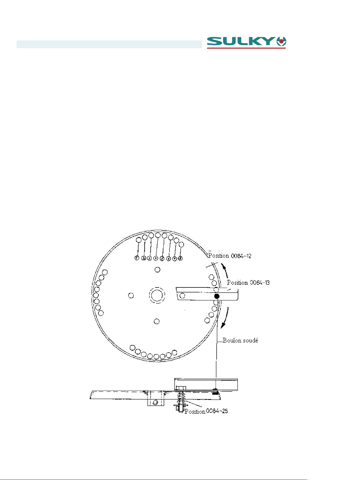
Réglage des ailettes d'épandage :
Le plateau d'épandage possède 4 ailettes d'épandage. La position de ces ailettes
peut être modifiée en les soulevant et en les tournant vers la droite ou la gauche
pour les fixer dans une autre position en les abaissant (voir pour cela le dessin cidessous). Les 4 ailettes doivent être réglées uniformément.
Dispersion de l'épandage trop à gauche : Tourner les ailettes dans le sens anti-ho-
Dispersion de l'épandage trop à droite : Tourner les ailettes dans le sens horaire.
Dessin : Réglage des ailettes d'épandage
Maniement
raire.
Épandeur centrifuge RS .................................................................................................................................................... Page 24

Maniement
5.5.Réglage mécanique de la quantité et de la largeur de l'épandage
La quantité d'épandage peut être réglée en déplaçant la trappe d'écoulement (paire de
leviers) sur l'échelle de 0 à 13. Les trappes d'écoulement s'ouvrent et se ferment en
conséquence dans la trémie (voir également 5.4 Réglage de la quantité et épandage limite).
La largeur d'épandage est réglée par le levage et l'abaissement mécanique du réducteur
de largeur d'épandage (voir également 5.4 réducteur de largeur d'épandage).
5.6.Commande hydraulique à distance
À l'aide de la commande hydraulique à distance. (standard)
Les trappes d'écoulement peuvent être ouvertes ou fermées depuis la cabine.
(voir également 5.4 réglage de la quantité et épandage limite).
5.7.Commande électrique à distance
À l'aide de la commande électrique à distance dépendant de la vitesse (option), la quantité d'épandage peut être réglée depuis la cabine de conduite. Les trappes d'écoulement
peuvent être ouvertes ou fermées depuis la cabine (voir également 5.4 réglage de la
quantité et épandage limite).
5.8.Régulation électrique de la quantité en fonction de la vitesse
La fonction de base est la même que la commande électrique à distance. Le conducteur
peut entrer en plus pour une vitesse définie X la quantité d'épandage Y dans l'appareil
de commande. Une fois cela effectué, la quantité d'épandage est adaptée automatiquement, mais le conducteur peut la modifier si nécessaire à n'importe quel moment.
À l'arrêt : Les trappes d'écoulement se ferment automatiquement
En marche : Les trappes d'écoulement s'ouvrent selon le réglage choisi
En cas de modification de la vitesse :
La quantité d'épandage est adaptée automatiquement à la vitesse de déplacement.
Épandeur centrifuge RS .................................................................................................................................................... Page 25

Maintenance
6. Maintenance
6.1.Généralités
Sécurisez ou améliorez les éléments suivants par des mesures de maintenance méticuleuses
- Fonctionnement
- Disponibilité
- Durée de vie de l'installation.
6.2.Inspection
Contrôlez avant chaque utilisation
- l'intégralité et le bon positionnement des goupilles de sécurité et des raccords
- si tous les dispositifs de sécurité sont fixés de façon correcte et conformément aux
prescriptions
- si les raccords hydrauliques éventuels sont raccordés correctement
- le cardan éventuel est raccordé correctement.
N'effectuez l'inspection que lorsque le moteur du véhicule tracteur est
coupé.
Risque d'accident !
6.3.Instructions d'entretien
Avant de commencer à suivre les instructions d'entretien, toutes les prescriptions d'entretien de l'épandeur centrifuge RS doivent être lues et tous
les points mentionnés observés ! Risque d'accident !
N'effectuez les travaux d'entretien, de réparation et de nettoyage que
lorsque le moteur du véhicule tracteur est coupé.
Épandeur centrifuge RS .................................................................................................................................................... Page 26

6.4.Tâches lors de l'entretien
Resserrez toutes les vis et tous les écrous et remplacez ceux qui manquent.
Contrôlez :
- le jeu de tous les paliers
- le bon positionnement de tous les éléments de fixation
(p.ex. dispositifs de protection)
- tous les éléments de l’attelage 3 points.
Contrôlez en particulier :
- le cardan (voir les instructions d'utilisation spécifiques)
Maintenance
- les éventuels dommages mécaniques sur les flexibles hydrauliques :
Les flexibles hydrauliques doivent être remplacés au maximum au bout
de 6 ans d'utilisation et après 2 ans de stockage. En cas de temps de
stockage élevé, le temps d'utilisation maximum réduit en conséquence
(date de fabrication des flexibles hydraulique, voir étiquette).
ATTENTION : De l'huile hydraulique jaillissant sous haute pression peut
pénétrer dans la peau et entraîner de graves blessures.
Remplacez l'huile du boîtier de renvoi d’angle une fois par an (env. 0,5 l
d'huile d'engrenage SAE 90).
Épandeur centrifuge RS .................................................................................................................................................... Page 27

Maintenance
6.5.Réparations
Pour les réparations, votre concessionnaire se tient à votre disposition. Si les réparations
sont effectuées par le personnel de l'utilisateur, l'intégralité des consignes des présentes
instructions de service doit être respectée ; nous déclinons en effet toute responsabilité
en cas de dommages et défaillances d'exploitation résultant du non-respect des présentes instructions d’utilisation.
Avant le début des réparations, l'épandeur doit être séparé de toutes les
sources d'entraînement. S'assurer que toute remise en marche non autorisée est impossible lors des réparations. Risque élevé d'accident !
Réinstaller impérativement les dispositifs de protection éventuellement
déposés lors des réparations avant l'activation de l'entraînement.
Risque élevé d'accident !
N'utilisez que des outils adaptés et dans un état irréprochable pour les
réparations !
Épandeur centrifuge RS .................................................................................................................................................... Page 28

Dear Customer
Dear Customer,
You have selected the Sulky Salt and Sand Spreader.
Thank you for your confidence in our equipment.
To ensure correct operation, and to make full use of your
spreader's possibilities, we recommend that you read this
operator's manual carefully.
Please do not hesitate to make suggestions or comments
based on your experience; they will always be of use to
us, and will help us improve our products.
Please return the duly completed guarantee form to us.
We wish you great success with your fertiliser spreader.
Yours sincerely,
J. BUREL
Chairman
RS Centrifugal Spreader.................................................................................................................................................... Page 29

In accordance with Appendix 2, Section 1, Point A of the European Machinery Directive 2006/42/EC.
Declaration of Conformity
NUFACTURER’SNAME AND ADDRESS
MA
N
ME AND ADDRESS OF THE PERSON AUTHORISED
A
TOCOMPILE THE TECHNICAL SPECIFICATIONS
CHINEDESCRIPTION
MA
TYPE :
:
:
SULKY-BUREL
PA DE LA GAULTIÈRE
35220 CHATEAUBOURG FRANCE
J
ULIEN
J
ULIEN
:
PA DE LA GAULTIÈRE
BURE L
BURE L
35220 CHATEAUBOURG FRANCE
SALT AND SAND SPREADER
RS 350 - RS 1000
SERIAL NUMBER :
ACCESSORIES :
Done at Châteaubourg: November 2011
THE MACHINE CONFORMS TO THE
RELEVANT TERMS OF THE
EUROPEAN
MACHINERY DIRECTIVE 2006/42/EC.
HE MACHINE ALSO CONFORMS TO THE
T
TERMS OF THE FOLLOWING DIRECTIVES
D
IRECTIVE CEM 2004/108/EC
GB
:
Signed:
J. BUREL
Chairman
RS Centrifugal Spreader.................................................................................................................................................... Page 30

Safety regulations
GB
Risk of accident
These symbols are used in these instructions every time recommendations are provided concerning your safety, the safety of others or the cor-
rect operation of the machine.
These recommendations must be given to all users of the machine.
GGEENNEERRAALL SSAAFFEETTYY RREEGGUULLAATTIIOONNSS
Every time the tractor/machine assembly is to be
started up and used, you should ensure beforehand that it complies with current legislation on safety at work and Road Traffic regulations.
GGEENNEERRAALL
1 - In addition to the instructions contained in this
manual, legislation relating to safety instructions
and accident prevention should be complied with.
2 - Warnings affixed to the machine give indications regarding safety measures to be observed
and help to avoid accidents.
3 - When travelling on public roads, abide by the
provisions of the Highway Code.
4 - Before starting work, it is essential that the
user familiarizes himself with the control and operating elements of the machine and their respective functions. When the machine is running, it may
be too late.
5 - The user should avoid wearing loose clothing
which may be caught up in the moving parts.
6 - We recommend using a tractor with a safety
cab or roll bar conforming to standards in force.
7 - Before starting up the machine and beginning
work, check the immediate surroundings, particularly for children. Make sure that visibility is adequate. Clear any persons or animals out of the
danger zone.
8 - It is strictly forbidden to transport any persons
or animals on board the machine whether it is in
operation or not.
9 - The machine should only be coupled up to the
tractor at the specially provided towing points and
in accordance with applicable safety standards.
10 - Extreme care must be taken when coupling or
uncoupling the machine from the tractor.
11 - Before hitching up the machine, ensure that
the front axle of the tractor is sufficiently weighted.
Ballast weights should be fitted to the special supports in accordance with the instructions of the
tractor manufacturer.
12 - Do not exceed the maximum axle weight or
the gross vehicle weight rating.
13 - Do not exceed the maximum authorized dimensions for using public roads.
14 - Before entering a public road, ensure that the
protective and signalling devices (lights, reflectors,
etc.) required by law are fitted and working properly.
15 - All remote controls (cords, cables, rods,
hoses, etc.) must be positioned so that they cannot
accidentally set off any manoeuvre which may
cause an accident or damage.
Risk of damage to the machine
16 - Before entering a public road, place the ma-
chine in the transport position, in accordance with
the manufacturer’s instructions.
17 -. Never leave the driver’s position whilst the
tractor is running.
18 - The speed and the method of operation must
always be adapted to the land, roads and paths.
Avoid sudden changes of direction under all circumstances.
19 - Precision of the steering, tractor adhesion,
road holding and effectiveness of the braking mechanism are influenced by factors such as the
weight and nature of the machine being towed, the
front axle stage and the state of the land or path. It
is essential, therefore, that the appropriate care is
taken for each situation.
20 - Take extra care when cornering, taking account of the overhang, length, height and weight of
the machine or trailer being towed.
21 - Before using the machine, ensure that all protective devices are fitted and in good condition.
Damaged protectors should be replaced immediately.
22 - Before using the machine, check that nuts
and screws are tight, particularly those for attaching tools (discs, flickers, deflectors, etc.). Tighten if necessary.
23 - Do not stand in the operating area of the machine.
24 - Caution! Be aware of any crushing and shearing zones on remote-controlled and particularly
hydraulically-controlled parts.
25 - Before climbing down from the tractor, or before any operation on the machine, turn off the engine, remove the key from the ignition and wait
until all moving parts have come to a standstill.
26 - Do not stand between the tractor and the
machine until the handbrake has been applied
and/or the wheels have been wedged.
27 -. Before any operation on the machine, ensure
that it
cannot be started up accidentally.
28 - Do not use the lifting ring to lift the machine
when it is loaded.
PPRROOPPEERR UUSSEE OOFF TTHHEE MMAACCHHIINNEE
The Spreader must only be used for tasks for
which it has been designed.
The manufacturer will not be liable for any damage
caused by using the machine for applications other
than those specified by the manufacturer.
Using the machine for purposes other than those
originally intended will be done so entirely at the
user’s risk.
Proper use of the machine also implies:
- complying with instructions on use, care and
maintenance provided by the manufacturer;
- using only original or manufacturer recommended spare parts, equipment and accessories.
The Spreader must only be operated, maintained
and repaired by competent persons, familiar with
the specifications and methods of operation of the
machine. These persons must also be informed of
the dangers to which they may be exposed.
The user must strictly abide by current legislation
regarding:
- accident prevention;
- safety at work (Health and Safety Regulations);
- transport on public roads (Road Traffic Regulations).
Strict compliance with warnings affixed to the machine is obligatory.
The owner of the equipment shall become liable
for any damage resulting from alterations made to
the machine by the user or any other person, without the prior written consent of the manufacturer.
- The noise emission value measured at the driving
position with the cab closed (level of acoustic
pressure) is 74 dB(A).
Measuring device: SL 401
Microphone positioned according to Appendix D,
paragraph D.2.2.4 of EN 1553.
This level of acoustic pressure essentially depends
on the tractor used.
HHIITTCCHHIINNGG
1 - When hitching or unhitching the machine from
the tractor, place the control lever of the hydraulic
lift in such a position that the lifting mechanism
cannot be activated accidentally.
2 - When hitching the machine to the three-point
lifting mechanism of the tractor, ensure that the
diameters of the pins or gudgeons correspond to
the diameter of the tractor ball joints.
3 - Caution! In the three-point lifting zone, there
may be a danger of crushing and shearing.
4 - Do not stand between the tractor and the machine whilst operating the external lift control lever.
5 - When in transport, lifting mechanism stabilizer
bars must be fitted to the machine to avoid floating
and side movement.
6 - When transporting the machine in the raised
position, lock the lift control lever.
DDRRIIVVEE EEQQUUIIPPMMEENNTT
(Power take-off and universal drive shafts)
1 - Only use universal drive shafts supplied with
the machine or recommended by the manufacturer.
Operating tip
RS Centrifugal Spreader.................................................................................................................................................... Page 31

B
G
2 - Power take-off and universal drive shaft guards
must always be fitted and in good condition.
3 - Ensure that the tubes of the universal drive
shafts are properly guarded, both in the working
position and in the transport position.
4 - Before connecting or disconnecting a universal
drive shaft, disengage the power take-off, turn off
the engine and re-move the key from the ignition.
5 - If the primary universal drive shaft is fitted with
a torque limiter or a free wheel, these must be
mounted on the machine power take-off.
6 - Always ensure that universal drive shafts are
fitted and locked correctly.
7 - Always ensure that universal drive shaft guards
are immobilized in rotation using the specially provided chains.
8 - Before engaging power take-off, ensure that
the speed selected and the direction of rotation of
the power take-off comply with the manufacturer’s
instructions.
9 - Before engaging power take-off, ensure that
no persons or animals are close to the machine.
10 - Disengage power take-off when the universal
drive shaft angle limits laid down by the manufacturer are in danger of being exceeded.
11 - Caution! When power take-off has been disengaged, moving parts may continue to rotate for
a few moments. Do not approach until they have
reached a complete standstill.
12 - On removal from the machine, rest the universal drive shafts on the specially provided supports.
13 - After disconnecting the universal drive shafts
from the power take-off, the protective cap should
be fitted to the power take-off.
14 - Damaged power take-off and universal drive
shaft guards must be replaced immediately.
HHYYDDRRAAUULLIICC CCIIRRCCUUIITT
1 - Caution! The hydraulic circuit is pressurized.
2 - When fitting hydraulic motors or cylinders, en-
sure that the circuits are connected correctly in accordance with the manufacturer’s guidelines.
3 - Before fitting a hose to the tractor’s hydraulic
circuit, ensure that the tractor-side and machineside circuits are not pressurized.
4 - The user of the machine is strongly recommended to identify the hydraulic couplings between the
tractor and the machine in order to avoid wrong
connection. Caution! There is a danger of reversing
the functions (for example: raise/lower).
5 - Check hydraulic hoses once a year:
. Damage to the outer surface
. Porosity of the outer surface
. Deformation with and without pressure
. State of the fittings and seals
The maximum working life for hoses is 6 years.
When replacing them, ensure that only hoses with
the specifications and grade recommended by the
machine manufacturer are used.
6 - When a leak is found, all necessary precautions
should be taken to avoid accidents.
7 - Pressurized liquid, particularly hydraulic circuit
oil, may cause serious injury if it comes into
contact with the skin. If the case of injury, consult a
doctor immediately. There is a risk of infection.
8 - Before any operation on the hydraulic circuit,
lower the machine, release the pressure from the
circuit, turn off the engine and remove the key
from the ignition.
MMAAIINNTTEENNAANNCCEE
1 - Before commencing any maintenance, servi-
cing or repair work, or before attempting to locate
the source of a breakdown or fault, it is essential
that the power take-off is disengaged, the engine
turned off and the key removed from the ignition.
2 - Check regularly that nuts and screws are not
loose. Tighten if necessary.
3 - Before carrying out maintenance work on a raised machine, prop it up using appropriate means
of support.
4 - When replacing a working part (fertilizer spreader blade or seed drill coulter), wear protective
gloves and only use appropriate tools.
5 - To protect the environment, it is forbidden to
throw away oil, grease or filters of any kind. Give
them to specialist recycling firms.
6 - Before operating on the electric circuit, disconnect the power source.
7 - Protective devices likely to be exposed to wear
and tear should be checked regularly. Replace
them immediately if they are damaged.
8 - Spare parts should comply with the standards
and specifications laid down by the manufacturer.
Only use Sulky spare parts.
9 - Before commencing any electric welding work
on the tractor or the towed machine, disconnect
the alternator and battery cables.
10 - Repairs affecting parts under stress or pressure (springs, pressure accumulators, etc.) should
be carried out by suitably qualified engineers with
special tools.
DANGER
1
1
1
Rotating agitator
Rotating disc
2
Fertiliser projections
3
Crushing hazard when hitching
3
3
2
2
RS Centrifugal Spreader.................................................................................................................................................... Page 32

Contents
1. Contents ............................................................................................................. 33
2. Introduction ...................................................................................................... 35
2.1. Contents of the documentation .......................................................................... 35
2.2. Explanation of the symbols and instructions ................................................. 36-37
2.3. Copyright ..................................................................................................................... 37
2.4. Description of the RS centrifugal spreader .................................................... 38
2.5. Technical characteristics ....................................................................................... 39
2.6. Fields of application and compliant use ......................................................... 39
3. Safety ................................................................................................................... 40
3.1. General safety instructions ................................................................................. 40-41
3.2. Safety at work .......................................................................................................... 41-42
3.3. Safety when work has finished ........................................................................... 42
3.4. Safety during maintenance ................................................................................... 43
3.5. Prohibition of arbitrary conversions .................................................................. 43
3.6. Hazards due to non-compliance with safety instructions ........................ 43
3.7. Guarantee and responsibility ............................................................................... 44
4. Assembly and dismantling ........................................................................ 45
4.1. Preliminary work: what should be done initially .......................................... 45
4.2. Mounting on the towing vehicle ................................................................. 46-47
4.3. Removal ....................................................................................................................... 47
4.4. Cleaning ....................................................................................................................... 48
5. Handling ............................................................................................................. 49
5.1. Guidelines .................................................................................................................... 49
5.2. Agitators ....................................................................................................................... 50
5.3. Filling with the product to be spread ............................................................... 50
5.4. Spreading quantity, distance, thickness and dispersion ......................... 51-52
5.5. Mechanical adjustment of the spreading quantity and width ............... 53
5.6. Remote hydraulic control ...................................................................................... 53
5.7. Remote electrical control ...................................................................................... 53
5.8. Electrical adjustment of the spreading quantity depending on the speed ....... 53
6. Maintenance .................................................................................................... 54
6.1. General points ............................................................................................................... 54
6.2. Inspection ........................................................................................................................ 54
6.3. Maintenance instructions ......................................................................................... 54
6.4. Maintenance tasks ...................................................................................................... 55
6.5. Repairs ............................................................................................................................. 56
RS Centrifugal Spreader.................................................................................................................................................... Page 33

RS Centrifugal Spreader.................................................................................................................................................... Page 34

Introduction
2. Introduction
2.1.Contents of the documentation
The purpose of writing this information is for those people responsible for the use of the
RS 350 or RS 1000 centrifugal spreader to read, understand and comply with all the
points mentioned.
The complete documentation must always be kept near to the centrifugal spreader.
The methods that are particularly important for the use of the centrifugal spreader are
shown in the present instructions for use.
Awareness of these instructions for use is the only way to prevent errors on the centrifugal spreader and ensure use without incidents. It is, therefore, very important that those
people responsible for its use also understand the instructions for use.
We will not take any responsibility for damage and operating defects resulting from nonadherence to these instructions for use.
First of all, we suggest you gain an overall idea of the structure of these instructions.
Please inform us of any difficulties you encounter with the instructions for use, for any
reason whatsoever.
These instructions only relate to
The RS 350 and RS 1000 Centrifugal Spreaders.
The diagrams and information in these instructions are subject to technical modifications necessary to improve the centrifugal spreader.
RS Centrifugal Spreader.................................................................................................................................................... Page 35

Introduction
2.2.Explanation of the symbols and instructions
The following symbols and illustrations attract your attention to important information. They
are also designed to facilitate the search for descriptions or additional items.
Safety at work symbol.
You will find this symbol for all the safety at work instructions found in these
instructions for use, for cases where there is a danger of bodily harm or
death. Adhere to these recommendations and be careful in the relevant situations.
Also tell other users about all the safety at work recommendations. Apart
from the recommendations in these instructions for use, generally accepted
recommendations for safety and prevention of accidents must be observed.
CAUTION!
CAUTION! appears in these instructions where particular attention is required in order to adhere to the directives, instructions, recommendations and
the correct working procedures, and to prevent damage and/or destruction
of the machine and/or other parts of the installation.
Danger due to rotating parts
Information
This symbol indicates the information necessary for in-depth understanding
of the instructions.
RS Centrifugal Spreader.................................................................................................................................................... Page 36

Introduction
A
DDRESS
If you have a problem, SULKY specialists are at your disposal on request. If assembly and putting into service are carried out by the staff of the user, all the
recommendations in these instructions for use must be observed. Indeed, we
cannot accept any responsibility for any damage or operating defects resulting
from non-adherence to these instructions for use.
We can be contacted at the following address:
SULKY-BUREL
Les Portes de Bretagne
P.A. de la Gaultière
20 35220 CHÂTEAUBOURG France
Tel: (33)02-99-00-84-84
Fax: (33)02-99-62-39-38
We are available to answer any questions
2.3.Copyright
©1998
This documentation is protected by copyright. The associated rights, all or in part, and
especially those of translation, reprinting, use of illustrations, radio broadcasting, reproduction on photo-mechanical means or similar, and recording of data processing documents, are reserved.
Subject to technical modifications.
RS Centrifugal Spreader.................................................................................................................................................... Page 37

Introduction
2.4.Description of the RS centrifugal spreader
The SULKY RS centrifugal spreader is designed for spreading products that flow freely
such as gravel, sand or salt on roads and pathways.
An articulated shaft or the hydraulic system of the tractor vehicle drives the agitators.
The SULKY RS centrifugal spreader is delivered with the following standard equipment:
- Spreader with Cat. I or II 3-point linkage or with an additional truck for a fixed mounting
- Protective grid
- Agitator
- Universal joint
- Gear unit with treated conical bearings
- Spreading width reducer
- Reflector
- Lighting support
- Anti-rust treatment and high quality paint (orange = RAL 2004, grey = RAL 7021)
- Upper yoke
- Lower linkage eyebolt
The following parts may be delivered as accessories:
- Mixer (agitator)
- Hydraulic drive
- Hopper cover
- 3-chamber rear tail light
- Guard to protect the tow unit
- Remote hydraulic control
- Remote electrical control
- Adjustment of the spreading quantity depending on the speed
- Reflective signalling plates
RS Centrifugal Spreader.................................................................................................................................................... Page 38

Introduction
2.5.Technical characteristics
Drive: Power take-off/hydraulic
Hopper capacity: from 120 to 1000 litres
Rotation speed of the power take-off: 540 rpm
2.6.Fields of application and compliant use
The SULKY RS centrifugal spreader is only designed for spreading products that flow
freely such as gravel, sand or salt on roads and pathways. The RS spreader may also be
used for fertilisers.
The offer and order confirmation, as well as the types of use, are part of the instructions.
Use other than that defined is considered to be non-compliant and is no longer the responsibility of SULKY.
SULKY declines all responsibility for damages resulting from non-compliant use; the
user alone will be liable for the risks.
Adherence to the safety instructions and observance of the inspection and maintenance
conditions are also an integral part of compliant use.
RS Centrifugal Spreader.................................................................................................................................................... Page 39

Safety
3. Safety
The following information about safety is of great importance.
These instructions for use have been drawn up with great care. If you have a made-to-measure model of this machine for which additional information is necessary, it is the responsibility of the user of the machine to contact
SULKY-BUREL
Les Portes de Bretagne
P.A. de la Gaultière
35220 CHATEAUBOURG France
Tel.: (33)02-99-00-84-84
Fax: (33)02-99-62-39-38
3.1.General safety instructions
The SULKY RS centrifugal spreader is built in accordance with the most up-to-date techniques and its operation is safe. However, hazards can result from use of the equipment:
- if there is non-compliant handling by untrained personnel
- in the event of non-compliant use
- if there is non-adherence to the recommendations mentioned in these operating
and maintenance instructions.
We expressly draw your attention to the following points:
- Observe the instructions and safety instructions (e.g. instructions for the
prevention of accidents, Road Traffic Act, etc.) to ensure the safety and incident-free operation of this spreading equipment.
- These instructions for use contain important recommendations for completely safe operation of the spreader. Anyone working on or with the
spreader must adhere to them.
- The user of the spreader agrees only to allow people to work with it who
have:
* familiarised themselves with the basic instructions for safety at work and
accident prevention, who are trained in handling spreaders’, and
* who have read and understood the safety chapter and the warnings in
the safety instructions.
RS Centrifugal Spreader.................................................................................................................................................... Page 40

Safety
In addition, we expressly draw your attention to the following points:
- Before starting work, anyone responsible for work on and with the
spreader agrees to:
* observe the basic instructions for safety at work and accident preven-
tion
* have read and understood the safety chapter and the warnings in the
safety instructions.
- The equipment must be compliant with the provisions of the Road Traffic Act and the Road Traffic Type Approval Law (e.g. lighting, warning
notices, etc.) as soon as it is used on a public thoroughfare.
Even tractors with equipment, which are not used on a public thoroughfare, are subject to the provisions concerning weights and axle
loads.
3.2.Safety at work
- Before using, ensure that the attaching parts are correctly positioned,
especially those for the projection discs and blades.
- The spreader should only be filled with the product to be spread when
the towing vehicle engine is turned off, the ignition key removed and
the applicator chutes are closed.
- Before adjustment or other work (e.g. lubricating or cleaning the spreader) deactivate the power take-off, turn off the engine and remove the
ignition key. Wait until all the rotating parts have stopped completely.
- Never place hands, feet or clothing in the vicinity of moving parts.
Avoid wearing loose clothing. Do not place your hands in the spreader
– Rotating tools!
- Do not put foreign bodies in the spreader reservoir.
- Before activation and during use of the spreader, the user must ensure
there is no-one in the hazardous area around the spreader. Ensure
there is sufficient visibility!
(Continued on the following page)
RS Centrifugal Spreader.................................................................................................................................................... Page 41

(Safety at work continued)
- The spreader must only be put into service if all the safety devices are installed correctly. The spreader warning notices must be replaced if they are
missing or illegible.
- Before starting spreading, everyone must leave the spreader projection
area. The projected spreading products constitute a hazard!
- Never leave the spreader in operation without surveillance.
- Carrying people on the spreader during transport and use is prohibited.
- Comply with the weight-on-wheels for the front wheels of the towing vehicle. Behaviour when being driven, as well as turning and braking capacity,
is influenced by the coupled equipment. Therefore ensure there is sufficient vehicle turning and braking capacity. Also comply with the authorised load per axle and total weight of the vehicle. Adapt your driving to
weather conditions and the modified dynamics.
Safety
- If there is damage, the spreader must be stopped immediately. Remove
the ignition key from the vehicle and repair the damage before the spreading equipment is used again. The same goes for damage to the universal
joint.
- A non-compliant selection or use of spreading products may cause serious bodily harm as well as harm to animals, plants and the environment.
So read the manufacturer’s instructions and those for spreading products
and select the correct product for the intended use.
3.3.Safety when work has finished
- Before leaving the vehicle, the spreader must be placed on the ground,
the engine turned off and the ignition key removed.
- If the spreader is uncoupled, the reservoir must be empty and the storage
surface must be flat and stable.
RS Centrifugal Spreader.................................................................................................................................................... Page 42

3.4.Safety during maintenance
- Before adjustment or other work (e.g. lubricating or cleaning the spreader) deactivate the power take-off, turn off the engine and remove the
ignition key. Wait until all the rotating parts have stopped completely.
- Make sure that during the checks and repairs no-one unintentionally
starts the spreading equipment.
- No-one must stand between the vehicle and the spreader without the
correct safety measures to maintain the vehicle in the stopped position,
using the handbrake and/or stop chocks.
DANGER OF INJURY DUE TO ROTATING PARTS
Only start the spreader when all the safety devices are mounted and secured.
Safety
Check that the RS centrifugal spreader is ready to operate and in perfect condition!
3.5.Prohibition of arbitrary conversions
No modifications whatsoever should be undertaken on the RS centrifugal spreader or its
accessories without the express, written authorisation of SULKY.
3.6.Hazards due to non-compliance with safety instructions
- Danger of bodily injury or death for the user or a third party.
- Damage to the machine and other material goods belonging to the user.
- Hazards for the working efficiency of the machine.
RS Centrifugal Spreader.................................................................................................................................................... Page 43

Safety
3.7. Guarantee and responsibility
The rights of the guarantee and responsibility for damage to people and property are excluded if these are attributable to one or several of the following causes:
- Non-compliant use of the spreading machine
- Incorrect assembly, putting into service, use or maintenance of the spreader
- Use of spare parts that are not original or authorised by the manufacturer
- Operation of the spreader with defective safety devices or devices that are installed in
a non-compliant manner, or with safety and protection devices in poor condition
- Non-adherence to the safety instructions concerning transport, storage, assembly, putting into service, use, maintenance and preparation of the spreader
- Arbitrary construction modifications on the spreader
- Defective monitoring of the machine parts subject to wear
- Non-compliant repairs
- If a catastrophe is triggered by the effect of a foreign body or a force majeur.
RS Centrifugal Spreader.................................................................................................................................................... Page 44

Assembly and dismantling
4. Assembly and dismantling
When assembling the spreader and putting it into service, ensure that all the recommendations in the instructions for use are observed.
4.1.Preliminary work: what should be done initially
If necessary, check that the spreading vehicle you wish to use:
- has sufficient output power
- generates the required hydraulic pressure
- has sufficient maximum load per axle
- has lifting connectors of the appropriate size.
RS Centrifugal Spreader.................................................................................................................................................... Page 45

Assembly and dismantling
4.2.Mounting on the towing vehicle
Mounting should only be carried out by trained, qualified personnel.
Move the towing vehicle up to the machine.
For the 3-point assembly:
- Lower the bottom arms to the mounting height.
- Place the hydraulic lift in the floating position.
- Turn of the tractor engine!
- Connect the bottom arms onto the spreader chassis bolt and secure it
with the pins with drop side rings.
- Align the spreader with the middle of the spreading vehicle.
- Fix the third point and secure it with the pins with drop side rings.
For the fixed mounting with support truck:
- On the spreading vehicle fix the support truck supplied to the points intended for this.
- Then fix the spreader on the support truck with the 2 screws at the top
and the 2 bolts at the bottom and secure with pins with drop side rings.
For the drive by power take-off:
- Then check
instructions for the universal joint):
- Measure between the edge of the towing vehicle power take-off and the
start of the gear unit connection.
the length of the universal joint (for this also see the operating
- Then take off about 30 mm from the measurement noted and shorten the
universal joint accordingly. Connect the articulated shaft and check that
this still has free space in the sliding area during lifting and lowering of
the spreader. Ensure that the universal joint is at the stop on both sides or
that it is secured by an adjustment screw.
RS Centrifugal Spreader.................................................................................................................................................... Page 46

4.3.Dismantling
Assembly and dismantling
For the hydraulic drive:
- Connect the hydraulic hoses to the corresponding hydraulic connectors
on the towing vehicle, in compliance with the markers (red = pressure,
blue = return).
Mounting and removal should only take place when the spreader is
stopped.
DANGER OF INJURY DUE TO ROTATING PARTS
- Lower the spreader onto a fixed, flat surface.
- Place the hydraulic lift in the floating position.
- Turn off the towing vehicle engine and put on the handbrake.
- If necessary unscrew the hydraulic pipes or the universal joint.
For the 3-point assembly:
- Unscrew the pin with drop side ring on the bottom arms and remove
these from the linkage eye-bolts.
- Unscrew the pin with drop side ring on the third point and take it off.
For the fixed mounting with support truck:
- Take off the screws at the top and the nuts at the bottom and uncouple
the spreader.
- Secure the uncoupled spreader so that it does not tip over!
RS Centrifugal Spreader.................................................................................................................................................... Page 47

Assembly and dismantling
4.4.Cleaning
Maintenance of the spreading machine must not be neglected, particularly during winter
usage.
After spreading salt and mixtures, the spreader must be cleaned as soon as possible after
use with water (do not use aggressive cleaning products or thinners).
Ensure that the water does not penetrate the bearings or the cavities.
If you use a high pressure cleaner make sure you only do so from a sufficient distance, 500
mm at least (damage to the paintwork!). Never direct the high pressure cleaner jet directly
onto bearings.
If a high pressure cleaner is used it is essential that hot water is not used.
If the machine is not used for a long period, it is recommended that organic oil (environmentally friendly!) is sprayed on the sheet metal parts once these are dry. Similarly the agitator and the mixer should be greased in position on the shaft.
RS Centrifugal Spreader.................................................................................................................................................... Page 48

Handling
5. Handling
5.1.Guidelines
The RS centrifugal spreader must only be put into service if all the following prior conditions are fulfilled:
- Perfect technical condition
- Compliant use
- Working in complete safety and being aware of the hazards
- Adherence to the instructions for use.
Eliminate defects that could have an adverse effect on safety immediately.
Before use, check that
- the upper and lower arms are correctly fixed
- all the safety pins (pins with drop side rings, spring pins) are available
and correctly assembled
- the universal joint and the hydraulic connections are correctly connected if necessary.
RS Centrifugal Spreader.................................................................................................................................................... Page 49

Handling
5.2.The agitators
To provide a constant flow of the various types of spreading products, 3 different agitators
are applied alternately to the plate shaft passing via the bottom of the hopper, using a bayonet fastener.
- Agitator: For all products that flow easily (e.g. gravel, granulates, dry sand) –
standard equipment
- Rotary mixer: Only for spreading products that do not flow easily (e.g. wet sand,
mixture of salts and mixture of different spreading products) –
(standard on RS 350).
CAUTION: Not appropriate for gravel!
- Vibrating mixer:
high performance For spreading products that do not flow easily, as with rotary mixer
(standard on RS 1000)
CAUTION: Not appropriate for gravel!
5.3.Filling with the product to be spread
The spreader may be filled with sand, salt, gravel or fertiliser.
- Firstly close the flow door in the hopper.
- Fix the agitator on the plate shaft , passing by the bottom of the hopper,
using a bayonet fastener.
- Then fill with the product to be spread.
If using the rotary mixer:
- Fill with the product to be spread to about 30 cm from the bottom of the
hopper.
- Then place the rotary mixer vertically in the middle.
- Then fill with the rest of the product to be spread.
CAUTION:
The gears may be subject to damage if these instructions are not observed!
RS Centrifugal Spreader.................................................................................................................................................... Page 50

Handling
5.4.Spreading quantity, distance, thickness and dispersion
The spreading quantity, distance, thickness and dispersion are influenced by various factors and spreader adjustments. The product to be spread depends on all these factors.
The following factors define the corresponding adjustments:
Spreading quantity: - Moving speed (rotation speed)
- Adjustment of the quantity (flow door)
Spreading thickness: - Moving speed (rotation speed)
- Adjustment of the quantity (flow door)
- Adjustment of the spreading width reducer
Spreading distance: - Moving speed (rotation speed)
- Adjustment of the spreading width reducer
Spreading dispersion: - Adjustment of the projection blades on the spreading disc
- Adjustment of the flow door
To change the corresponding factors the following steps are necessary:
Adjustment of the quantity (flow door)
The mechanical flow door (pair of levers) on the RS centrifugal spreader has a scale
of 0 to 13, with 0 meaning "closed" and 13 "fully open".
At the maximum or optimal adjustment, the stop installed on the scale may be defined with the butterfly nut in the corresponding scale position so that the maximum
opening may not be exceeded or the optimal opening may be adjusted slightly.
“Limit spreading”
Due to the mechanical separation of the pair of levers (unscrew the assembly
screw),the left and right flow doors of the spreader may be opened or closed separately. Depending on the adjustment of the left-hand or right-hand flow door, the
spreading dispersion may be offset to the left or the right..
Spreading width reducer
The spreading width reducer limits the projection distance of the product to be
spread. The more the spreading width reducer installed on the hopper is lowered mechanically above the surface of the spreading disc, the more the distance and thickness of spreading is limited.
RS Centrifugal Spreader.................................................................................................................................................... Page 51

Adjustment of the spreading blades
The spreading disc has 4 spreading blades. The position of these blades can be
changed by lifting them, and by turning them to the left or right to fix them in another position by lowering them (see the diagram below for this). The 4 blades must
be adjusted evenly.
Dispersion of spreading too far to the left: Turn the blades anti-clockwise.
Dispersion of spreading too far to the right: Turn the blades clockwise.
Diagram: Adjustment of the spreading blades
Handling
RS Centrifugal Spreader.................................................................................................................................................... Page 52

Handling
5.5.Mechanical adjustment of the spreading quantity and width
The spreading quantity may be adjusted by moving the flow door (pair of levers) on a
scale of 0 to 13. The flow doors open and close in the hopper accordingly (also see 5.4.
Adjustment of quantity and limit of spreading).
The spreading width is adjusted by the mechanical raising and lowering of the spreading
width reducer (also see 5.4 Spreading width reducer).
5.6.Remote hydraulic control
Using the remote hydraulic control. (standard)
The flow doors may be opened and closed from the cab (also see 5.4 Adjustment of
quantity and limit of spreading).
5.7.Remote electrical control
Using the remote electrical control depending on the speed (optional), the spreading
quantity may be adjusted from the driver’s cab. The flow doors may be opened or closed
from the cab (also see 5.4 Adjustment of quantity and limit of spreading).
5.8.Electrical adjustment of the spreading quantity depending on the speed
The basic function is similar to that of the remote electrical control. The driver may also
enter the spreading quantity Y for a defined speed X into the control equipment. Once
this is done, the spreading quantity is adapted automatically, but the driver can change it
at any time if required.
When stopped: The flow doors close automatically
When moving: The flow doors open according to the setting chosen
If the speed is modified:
The spreading quantity is adapted automatically to the
speed of travel.
RS Centrifugal Spreader.................................................................................................................................................... Page 53

6. Maintenance
6.1.General points
Make safe or improve the following items by meticulous maintenance measures:
- Operation
- Availability
- Service life of the equipment.
6.2.Inspection
Before using check
- that the safety pins and connectors are intact and correctly positioned
Maintenance
- that all the safety devices are fixed correctly and in compliance with the instructions
- that hydraulic connectors, if fitted, are properly connected
- that the universal joint, if fitted, is correctly connected.
Only carry out the inspection when the engine of the towing vehicle is turned off.
Accident risk!
6.3.Maintenance instructions
Before starting to carry out the maintenance instructions, all the recommendations for the maintenance of the RS centrifugal spreader must be read
and all the points mentioned observed! Accident risk!
Only carry out maintenance work, repairs and cleaning when the engine of
the towing vehicle is turned off.
RS Centrifugal Spreader.................................................................................................................................................... Page 54

6.4.Maintenance tasks
Tighten all the screws and nuts and replace any that are missing.
Check:
- the play in all the bearings
- correct positioning of all the fittings
- all the three-point linkage elements.
In particular, check:
- the universal joint (see the specific instructions for use)
Maintenance
(e.g. safety devices)
- for possible mechanical damage to the hydraulic hoses.
The hydraulic hoses must be replaced after a maximum of 6 years of use
and 2 years of storage. If there is a long storage time, the maximum period of use is reduced accordingly (for date of manufacture for the hydraulic hoses, see label).
CAUTION: Hydraulic fluid spurting out under high pressure may pene-
trate the skin and cause serious injury.
Replace the gear unit oil once a year (approx. 0.5 l of gear oil, SAE 90).
RS Centrifugal Spreader.................................................................................................................................................... Page 55

Maintenance
6.5.Repairs
Your dealer is at your disposal for repairs on request. If repairs are carried out by the
staff of the user, all the recommendations in these operating instructions must be observed. Indeed, we cannot accept any responsibility for any damage or operating defects
resulting from non-adherence to these instructions for use.
Before starting repairs the spreader must be uncoupled from any drive
sources. Ensure that any unauthorised starting of the equipment is impossible during repairs. High accident risk!
It is essential to re-install the safety devices that may have been dismantled during repairs before the drive is started.
High accident risk!
Only use appropriate tools, which are in impeccable condition, for repairs!
RS Centrifugal Spreader.................................................................................................................................................... Page 56

Sehr geehrter Kunde
Geehrter Kunde,
Sie haben sich für einen Salz- und Sandstreuer von Sulky
entschieden. Wir danken Ihnen für das Vertrauen, das Sie
unseren Geräten entgegenbringen.
Bitte lesen Sie die Anleitung sorgfältig durch, damit Sie
Ihren Düngerstreuer richtig benutzen und alle seine Möglichkeiten voll nutzen können.
Zögern Sie nicht, uns Ihre eigenen Beobachtungen und
Erfahrungen mitzuteilen, die für die Verbesserung unserer
Produkte immer nützlich sein können.
Garantieschein bitte ausgefüllt an uns zurückschicken.
Wir wünschen Ihnen viel Erfolg mit Ihrem Düngerstreuer
und verbleiben
mit freundlichen Grüßen
J. BUREL
Geschäftsleiter
Schleuderstreuer RS .......................................................................................................................................................... Seite 57

Gemäß Anhang II, Teil 1, Abschnitt A der Maschinenrichtlinie 2006/42/EG.
Konformitätserklärung
ME UNDADRESSE DESHERSTELLERS
NA
ME UNDADRESSE DES FÜR DIEZUSAMMENSTELLUNG
NA
DER TECHNISCHEN
SCHREIBUNG DERMASCHINE
BE
UNTERLAGEN BEVOLLMÄCHTIGTEN :
:
SULKY-BUREL
PA DE LA GAULTIÈRE
35220 CHATEAUBOURG FRANCE
J
ULIEN
J
ULIEN
BURE L
BURE L
PA DE LA GAULTIÈRE
35220 CHATEAUBOURG FRANCE
:
SALZ- UND SANDSTREUER
TYP :
SERIENNUMMER :
ZUSATZAUSRÜSTUNGEN :
RS 350 - RS 1000
DIE MASCHINE ENTSPRICHT ALLEN
EINSCHLÄGIGEN BESTIMMUNGEN DER
MASCHINENRICHTLINIE 2006/42/EG
D
IE MASCHINE ENTSPRICHT
DEN BESTIMMUNGEN
DER NACHFOLGENDEN RICHTLINIEN:
EMV-R
ICHTLINIE 2004/108/EG
DE
Châteaubourg, November 2011
Unterzeichnet:
J. BUREL
Geschäftsführer
Schleuderstreuer RS .......................................................................................................................................................... Seite 58

Sicherheitsvorschriften
E
D
Verletzungsgefahr
In der Anweisung werden diese Zeichen in Verbindung mit Empfehlungen für Ihre Sicherheit und den einwandfreien Betrieb der Maschine ver-
wendet..
Jeder Benutzer dieser Maschine muß diese Vorschriften genau kennen.
AALLLLGGEEMMEEIINNEE SSIICCHHEERRHHEEIITTSSVVOORRSSCCHHRRIIFFTTEENN
Vor jeder Benutzung und Inbetriebsetzung der
Schlepper-Maschinen-Einheit kontrollieren, ob sie
den Sicherheitsvorschriften und den Vorschriften
der Straßenverkehrsordnung entspricht..
AALLLLGGEEMMEEIINNEESS
1 - Zusätzlich zu den in diesem Handbuch enthal-
tenen Anweisungen ist die Gesetzgebung bezüglich der Sicherheits- und
Unfallverhütungs-vorschriften einzuhalten.
2 - Die auf der Maschine angebrachten Warnungen informieren über die einzuhaltenden Sicherheitsmaßnahmen und tragen zur Unfall-verhütung
bei.
3 - Im Straßenverkehr die Straßenverkehrsordnung
einhalten.
4 - Der Benutzer hat sich unbedingt vor Arbeitsbeginn mit den Antriebs- und Bedienungsorganen
der Maschine und ihren jeweiligen Funktionen vertraut zu machen.
5 - Weite Kleidungsstücke vermeiden, die in sich
bewegende Teile geraten könnten.
6 - Es empfiehlt sich, gemäß der gültigen Normen
einen Schlepper mit Kabine oder Sicherheits-verstärkung zu verwenden.
7 - Vor Inbetriebnahme und Arbeitsbeginn die direkte Umgebung kontrollieren (Kinder!). Für ausreichende Sicht sorgen! Personen oder Tiere aus
dem Maschinengefahrenbereich entfernen
(Schutzvorrichtungen!).
8 - Der Transport von Personen oder Tieren auf der
Maschine ist während der Arbeit oder beim Fahren
streng verboten.
9 - Die Maschine darf gemäß der geltenden Sicherheitsnormen nur an den dafür vorgesehenen
Kupplungspunkten angehängt werden.
10 - Besondere Vorsicht ist beim An- und Ab-kuppeln der Maschine geboten.
11 - Vor dem Anhängen der Maschine kontrollieren, ob der Ballast des Schleppers ausreicht. Die
Ballastelemente müssen gemäß der Vorschriften
des Schlepperherstellers auf den dafür vorgesehenen Haltern angebracht werden.
12 - Die maximale Achslast und das zulässige Gesamtgewicht einhalten.
13 - Das für den Straßenverkehr maximal zulässige Außenmaß einhalten.
14 - Vor Straßenbenutzung die Schutz-vorrichtungen und Signalisierungsvorrichtungen (Licht- und
Reflektorelemente) anbringen und ihre Funktion
prüfen.
Gefahr der Beschädigung der Maschine
15 - Alle Fernsteuerungen (Seil, Kabel, Stange,
Schlauch) müssen so positioniert sein, daß sie
nicht ungewollt betätigt werden und dadurch Unfälle oder Schäden hervorrufen können.
16 - Vor Straßenbenutzung die Maschine gemäß
Herstelleranweisungen in Transportstellung bringen.
17 - Nie bei laufender Maschine den Fahrersitz
verlassen.
18 - Fahrgeschwindigkeit und -weise müssen
immer dem Gelände, den Straßen und Wegen angepaßt sein. Plötzliche Richtungsänderungen vermeiden.
19 - Die Präzision der Lenkung, die Bodenhaftung
des Schleppers, die Straßenlage und die Wirksamkeit der Bremsvorrichtung werden von folgenden
Faktoren beeinflußt : Gewicht und Art der angekuppelten Maschine, Belastung der Vorderachse,
Zustand des Geländes oder der Fahrbahn. Die entsprechenden Vorsichtsmaßnahmen einhalten.
20 - Besondere Vorsicht ist in Kurven geboten.
Schwerpunktlage, Länge, Höhe und Gewicht der
Maschine oder des Anhängers berücksichtigen.
21 - Vor jeder Benutzung der Maschine kontrollieren, ob alle Schutzvorrichtungen angebracht und in
gutem Zustand sind. Bei Beschädigung sofort austauschen.
22 - Vor jeder Benutzung kontrollieren, ob alle
Schrauben und Muttern fest angezogen sind, insbesondere diejenigen, mit denen die Geräte befestigt sind (Scheiben, Paletten, Schirme...). Notfalls
anziehen.
23 - Sich nicht im Manövrierbereich der Maschine
aufhalten.
24 - Vorsicht ! Auf der Fernsteuerungseinrichtung,
insbesondere beim hydraulischen Regelkreis, kann
es Stauch- und Abscherzonen geben.
25 - Vor Verlassen des Schleppers oder vor jedem
Eingriff in die Maschine Motor abschalten, Zündschlüssel abziehen und völligen Stillstand aller beweglichen Teile abwarten.
26 - Sich nicht zwischen Schlepper und Maschine
aufhalten, ohne zuvor die Standbremse angezogen
und/ oder Keile unter die Räder gelegt zu haben.
27 - Vor jedem Eingriff in die Maschine kontrollieren, ob diese nicht ungewollt in Betrieb gesetzt
werden kann.
28 - Die Aufhängöse nicht zum Heben der gefüllten Maschine benutzen.
BBEESSTTIIMMMMUUNNGGSSGGEEMMÄÄSSSSEE VVEERRWWEENNDDUUNNGG
DDEERR MMAASSCCHHIINNEE
Der Rotorstreuer darf nur für die Arbeiten eingesetzt werden, für die er konzipiert ist. Bei Beschädigung der Maschine infolge einer nicht vom
Hersteller spezifizierten Benutzung ist dieser nicht
haftbar.
Hinweis zur Arbeitserleichterung
Jede nicht der ursprünglichen Bestimmung der
Maschine entsprechende Benutzung erfolgt auf
Kosten und Gefahr des Benutzers.
Die bestimmungsgemäße Verwendung der Maschine setzt ebenfalls voraus:
- die Einhaltung der vom Hersteller vorgegebenen
Benutzungs-, Wartungs- und Instandsetzungs-vorschriften,
- die ausschließliche Verwendung von Originalersatzteilen, Originalausrüstungen und Originalzubehör oder von Teilen, die vom Hersteller empfohlen
sind.
Der Rotorstreuer darf nur von kompetenten, mit
den technischen Daten und Benutzungs-anweisungen vertrauten Personen benutzt, gewartet und repariert werden, die über die Risiken informiert sind,
denen sie ausgesetzt sein könnten.
Die geltenden Vorschriften bezüglich:
- der Unfallverhütung,
- der Sicherheit am Arbeitsplatz (Arbeitsgesetzbuch) und
- des Straßenverkehrs (Straßenverkehrsordnung)
sind strengstens einzuhalten.
Die an der Maschine angebrachten Warnungen
berücksichtigen.
Der Hersteller haftet nicht für Schäden, die durch
Abänderungen entstehen, die vom Benutzer oder
von Dritten ohne schriftliche Genehmigung an der
Maschine vorgenommen wurden.
- Der am Fahrersitz bei geschlossener Kabine gemessene Geräuschemissionswert (Schalldruckpegel) beträgt 74 dB(A).
Messgerät: SL 401
Position des angebrachten Mikrophons gemäß Paragraph D.2.2.4 des Anhangs D der Norm EN 1553.
Dieser Schalldruckpegel ist im Wesentlichen vom
verwendeten Schleppertyp abhängig.
AANNHHÄÄNNGGUUNNGG
1 - Beim An- und Abkuppeln der Maschine an den
Schlepper den Steuerhebel des Hydraulik-krafthebers so stellen, daß der Hubvorgang nicht ungewollt ausgelöst werden kann.
2 - Beim Anhängen der Maschine am Dreipunktkraftheber des Schleppers darauf achten, daß die
Spindel- oder Zapfendurchmesser dem Durchmesser der Schlepperkugelgelenke entsprechen.
3 - Vorsicht! Im Dreipunkt-Hubbereich bestehen
Stauch- und Abscherrisiken!
4 - Sich bei Betätigung des äußeren KraftheberSteuerhebels nicht zwischen Schlepper und Maschine aufhalten.
5 - Beim Transport muß die Maschine durch die
Versteifungsstreben des Krafthebers zur Vermeidung von Unwucht und seitlicher Pendelung stabilisiert werden.
Schleuderstreuer RS .......................................................................................................................................................... Seite 59

E
D
6 - Beim Transport der Maschine in angehobener
Stellung den Kraftheber-Steuerhebel blockieren.
AANNTTRRIIEEBBSSOORRGGAANNEE
(Zapfwelle und Gelenkwellen-Antrieb)
1 - Nur die mit der Maschine gelieferte oder vom
Hersteller empfohlene Gelenkwelle verwenden.
2 - Die Schutzvorrichtungen der Zapfwellen und
Gelenkwellen müssen immer angebracht und in
gutem Zustand sein.
3 - Auf die richtige Überlappung der Gelenkwellenrohre sowohl in Arbeits- als auch in Transportstellung achten.
4 - Vor Anschließen oder Abziehen einer Gelenkwelle die Zapfwelle auskuppeln, den Motor abschalten und den Zündschlüssel abziehen.
5 - Ist die Primärkardanwelle mit einem Drehmomentbegrenzer oder einer Freilaufkupplung ausgestattet, müssen diese unbedingt auf der
Zapfwelle der Maschine montiert sein.
6 - Immer auf die korrekte Montage und Verriegelung der Kardanantriebe achten.
7 - Immer darauf achten, daß die Schutzvorrichtungen der Gelenkwellen mit den dafür vorgesehenen Ketten gegen Verdrehen gesichert sind.
8 - Vor Kuppeln der Zapfwelle prüfen, ob die gewählte Drehzahl und die Drehrichtung der Zapfwelle den Vorschriften des Herstellers entsprechen.
9 - Vor Kuppeln der Zapfwelle kontrollieren, ob
sich keine Personen oder Tiere in Nähe der Maschine befinden.
10 - Die Zapfwelle auskuppeln, wenn Gefahr besteht, daß die vom Hersteller vorgeschriebenen
Grenzen des Gelenkwellenwinkels überschritten
werden.
11 - Vorsicht! Nach Auskuppeln der Zapfwelle
können Teile der Maschine noch einige Zeit nachlaufen. Sich ihnen nie vor völligem Stillstand nähern.
12 - Bei Abbau der Maschine die Gelenkwellen
auf den dafür vorgesehenen Haltern ablegen.
13 - Nach Abziehen der Gelenkwelle von der
Schlepperzapfwelle muß diese mit ihrer Schutzkappe bedeckt werden.
14 - Schadhafte Schutzvorrichtungen der Zapfwelle und der Gelenkwelle müssen sofort ausgewechselt werden.
HHYYDDRRAAUULLIIKKLLEEIITTUUNNGG
1 - Vorsicht! Die Hydraulikleitung steht unter
Druck.
2 - Bei Montage von Zylindern oder Hydraulik-motoren auf den korrekten Anschluß gemäß der Anweisungen des Herstellers achten.
3 - Vor Anschluß eines Schlauchs an die Hydraulikleitung des Schleppers dafür sorgen, daß die
schlepper- und maschinenseitigen Leitungen nicht
unter Druck stehen.
4 - Dem Benutzer der Maschine wird zur Vermeidung falscher Anschlüsse dringend geraten, die
Kennzeichnungen auf den Hydraulikanschlüssen
zwischen Schlepper und Maschine zu beachten, da
sonst die Gefahr einer Funktionsumkehrung besteht. (z.B.: Heben/Senken).
5 - Einmal im Jahr die Hydraulikschläuche kontrollieren auf:
. Beschädigung der Außenschicht
. Porosität der Außenschicht
. Verformung ohne Druck und unter Druck
. Zustand der Verbindungen und Dichtungen.
Die maximale Benutzungsdauer der Schläuche ist
6 Jahre. Beim Auswechseln darauf achten, daß nur
Schläuche verwendet werden, deren Eigenschaften
und Qualität den Vorschriften des Maschinenherstellers entsprechen.
6 - Bei Feststellung einer undichten Stelle alle Vorsichtsmaßnahmen zur Unfallverhütung treffen.
7 - Eine unter Druck stehende Flüssigkeit, insbesondere das Öl der Hydraulikleitung, kann die Haut
durchdringen und schwere Verletzungen verursachen! Bei Verletzungen sofort Arzt aufsuchen; Infektionsgefahr!
8 - Vor jedem Eingriff in die Hydraulikanlage Maschine ablassen, Anlage drucklos schalten, Motor
abstellen und Zündschlüssel abziehen.
WWAARRTTUUNNGG
1 - Vor Instandsetzungs-, Wartungs- oder Repara-
turarbeiten sowie beim Ermitteln einer Pannenoder Betriebsstörungsquelle muß die Zapfwelle
ausgekuppelt, der Motor abgeschaltet und der
Zündschlüssel abgezogen sein.
2 - Regelmäßig kontrollieren, ob Schrauben und
Muttern fest angezogen sind. Notfalls anziehen.
3 - Vor Wartung einer Maschine in angehobener
Stellung diese mit einem geeigneten Mittel abstützen.
4 - Beim Austausch eines Funktionsteiles (Schaufel bei Streuern oder Schare bei Drill-maschinen)
Schutzhandschuhe tragen und nur geeignete
Werkzeuge benutzen.
5 - Zum Schutz der Umwelt ist es verboten, Öl,
Fett und Filter jeder Art wegzuwerfen oder auszugießen. Sie sind von darauf spezialisierten Unternehmen zu entsorgen.
6 - Vor Eingriff an der elektrischen Leitung die
Stromzufuhr unterbrechen.
7 - Die Verschleiß ausgesetzten Schutzvor-richtungen müssen regelmäßig kontrolliert und bei
Schadhaftigkeit sofort ausgetauscht werden.
8 - Ersatzteile müssen den vom Hersteller fest-gelegten Normen und Kennwerten entsprechen. Nur
Sulky-Ersatzteile verwenden!
9 - Vor Elektroschweißarbeiten am Schlepper oder
an der angehängten Maschine die Kabel des
Wechselstromgenerators und der Batterie abziehen.
10 - Reparaturen an Teilen, die unter Spannung
oder Druck stehen (Federn, Druckspeicher usw.)
setzen eine ausreichende Qualifikation voraus und
erfordern Spezialwerkzeug; sie dürfen daher nur
von qualifiziertem Personal durchgeführt werden.
GEFAHR
1
1
1
Rotierendes Rührwerk
Rotierendes Rührwerk
2
Auswurf von Düngemitteln
Quetschgefahr beim
3
Ankuppeln
3
3
2
2
Schleuderstreuer RS .......................................................................................................................................................... Seite 60

1. Inhalt .................................................................................................................... 61
2. Einleitung ........................................................................................................... 63
2.1. Inhalt der Betriebsanleitung ................................................................................. 63
2.2. Erläuterung der Symbole und Sicherheitsanweisungen ...........................64-65
2.3. Urheberrechte ............................................................................................................ 65
2.4. Beschreibung des Schleuderstreuers RS ........................................................ 66
2.5. Technische Merkmale ............................................................................................ 67
2.6. Anwendungsbereiche und sachgemäßer Einsatz ....................................... 67
3. Sicherheit ........................................................................................................... 68
3.1. Allgemeine Sicherheitsanweisungen.................................................................68-69
3.2. Arbeitssicherheit .......................................................................................................69-70
3.3. Sicherheitsbestimmungen nach Abschluss der Arbeiten ......................... 70
3.4. Sicherheit während der Wartung ....................................................................... 71
3.5. Verbot eigenmächtiger Veränderungen .......................................................... 71
3.6. Gefährdung durch Nichtbeachtung der Sicherheitsanweisungen ........ 71
3.7. Garantie und Gewährleistung .............................................................................. 72
Inhalt
4. An- und Abmontieren .................................................................................. 73
4.1. Vorbereitende Maßnahmen: Was Sie ganz zu Anfang tun sollten........ 73
4.2. Anmontieren an das Streufahrzeug .................................................................. 74-75
4.3. Abmontieren ............................................................................................................... 75
4.4. Reinigung ..................................................................................................................... 76
5. Handhabung ..................................................................................................... 77
5.1. Allgemeine Richtlinien ............................................................................................ 77
5.2. Das Rührwerk ............................................................................................................ 78
5.3. Auffüllen des Streuguts .......................................................................................... 78
5.4. Menge, Reichweite, Schichtdicke und Streubreite .................................. 79-80
5.5. Mechanische Einstellung von Streumenge und -breite ............................ 81
5.6. Hydraulik-Fernsteuerung ....................................................................................... 81
5.7. Elektrische Fernsteuerung .................................................................................... 81
5.8. Geschwindigkeitsabhängige, elektrische Mengenregulierung ............................ 81
6. Wartung ............................................................................................................... 82
6.1. Allgemeines .................................................................................................................... 82
6.2. Kontrolle ........................................................................................................................... 82
6.3. Wartungsvorschriften .................................................................................................. 82
6.4. Arbeitsschritte während der Wartung .................................................................. 83
6.5. Reparaturen .................................................................................................................... 84
Schleuderstreuer RS .......................................................................................................................................................... Seite 61

Schleuderstreuer RS .......................................................................................................................................................... Seite 62

Einleitung
2. Einleitung
2.1.Inhalt der Betriebsanleitung
Die für die Bedienung des Schleuderstreuers RS 350 bzw. RS 1000 verantwortlichen
Personen müssen die vorliegenden Produktinformationen vor Inbetriebnahme vollständig
lesen und sicherstellen, dass sie diese verstehen und sich an alle aufgeführten Punkte
halten.
Die vollständigen Unterlagen müssen jederzeit in der Nähe des Schleuderstreuers aufbewahrt werden.
In der vorliegenden Gebrauchsanweisung sind alle für die Bedienung des Schleuderstreuers wichtigen Anweisungen aufgeführt.
Um Fehler bei der Bedienung des Schleuderstreuers zu vermeiden und Unfällen vorzubeugen, muss der Inhalt der vorliegenden Gebrauchsanweisung vor dem Gebrauch bekannt sein. Daher ist es wichtig, dass auch die Verantwortlichen die
Gebrauchsanweisung kennen.
Für Beschädigungen und Betriebsausfälle, die aufgrund der Nichtbeachtung der vorliegenden Gebrauchsanweisung entstehen, übernehmen wir keine Haftung.
Machen Sie sich zunächst ein Bild von der Gesamtstruktur dieser Gebrauchsanweisung.
Teilen Sie uns eventuelle Schwierigkeiten mit dieser Gebrauchsanweisung mit, egal welcher Natur diese auch sein mögen.
Die vorliegende Betriebsanleitung gilt ausschließlich für den:
Schleuderstreuer RS 350 und RS 1000.
Darstellungen und Angaben der vorliegenden Gebrauchsanweisung unter Vorbehalt zur
Verbesserung des Schleuderstreuers erforderlicher technischer Änderungen.
Schleuderstreuer RS .......................................................................................................................................................... Seite 63

Einleitung
2.2.Erläuterung der Symbole und Sicherheitsanweisungen
Die folgenden Symbole und Gefahrenhinweise deuten auf wichtige Sicherheitsanweisungen hin. Sie sollen außerdem dabei helfen, Beschreibungen und zusätzliches Material
schneller auffinden zu können.
Arbeitsschutzsymbol:
Dieses sämtliche Arbeitsschutzmaßnahmen betreffende Symbol finden Sie
in der vorliegenden Gebrauchsanweisung überall dort, wo auf Verletzungsoder Todesgefahren hingewiesen wird. Beachten Sie diese Gefahren hinweise und verhalten Sie sich in den angesprochenen Fällen mit gegebener
Vorsicht.
Unterrichten Sie auch alle weiteren Benutzer über sämtliche Arbeitsschutzhinweise. Neben den in der vorliegenden Gebrauchs anweisung aufgeführten Hinweisen sind auch die allgemeingültigen Sicherheits- und
Unfallverhütungsvorschriften zu beachten.
ACHTUNG!
Den Hinweis ACHTUNG! finden Sie in der vorliegenden Gebrauchsanweisung an den Stellen, wo im Sinne geltender Richtlinien, Vorschriften und
Hinweise sowie zur Gewährleistung eines korrekten Arbeitsablaufs besondere Aufmerksamkeit geboten ist, um eine Beschädigung und/oder Zerstörung der Maschine und/oder anderer Anlagenteile zu vermeiden.
Gefahren durch rotierende Teile
Hinweis:
Dieses Symbol weist auf Informationen hin, die zum gründlichen Verständnis der Anweisungen erforderlich sind.
Schleuderstreuer RS .......................................................................................................................................................... Seite 64

Einleitung
A
DRESSE:
Sollten Probleme auftreten, können Sie sich vertrauensvoll an die SULKY-Fachleute wenden. Sollten Installationen und Inbetriebnahmen durch das Personal
des Benutzers erfolgen, müssen die Hinweise der vorliegenden Gebrauchsanweisung vollständig beachtet werden. Für Beschädigungen und Störungen, die
aufgrund der Nichtbeachtung der vorliegenden Gebrauchsanweisung entstanden sind, übernehmen wir keine Haftung.
Sie können uns unter der folgenden Adresse kontaktieren:
SULKY-BUREL
Les Portes de Bretagne
P.A. de la Gaultière
20 35220 Châteaubourg
Frankreich
Tel.: 0033 - (0)2-99-00-84-84
Fax: 0033 - (0)2-99-62-39-38
Für Fragen jeglicher Art stehen wir Ihnen gerne zur Verfügung.
2.3.Urheberrechte
©1998
Die vorliegenden Unterlagen sind urheberrechtlich geschützt. Übersetzung, Nachdruck,
Verwendung grafischer Darstellungen, Verwendung in Funksendungen, Reproduktion in
Form von Fotokopien oder ähnlichen Methoden, sowie Erfassung und Vervielfältigung in
Datenverarbeitungsanlagen bedürfen der ausdrücklichen Genehmigung des Herausgebers.
Änderungen vorbehalten.
Schleuderstreuer RS .......................................................................................................................................................... Seite 65

Einleitung
2.4.Beschreibung des Schleuderstreuers RS
Der Schleuderstreuer RS von SULKY wurde speziell für den Einsatz mit rieselfähigen Produkten wie Rollsplitt, Sand oder Salz auf Fahrstraßen konstruiert.
Das Rührwerk wird durch eine Gelenkwelle oder die Hydraulik der Zugmaschine angetrieben.
Der Schleuderstreuer RS von SULKY wird serienmäßig mit folgendem Zubehör ausgeliefert:
- Streuer mit 3-Punkt-Kupplung der Kategorie I oder II, oder mit Zusatzwagen für Festinstallation
- Schutzgitter
- Rührwerk
- Gelenkwelle
- Winkelgetriebekasten mit behandelten Kegelrollenlagern
- Streubreitenbegrenzer
- Rückstrahler
- Beleuchtungshalterung
- Rostschutzbehandlung und hochwertige Lackierung (orange = RAL 2004; grau = RAL
7021)
- Oberes Kupplungsgelenk
- Unterer Kupplungsbolzen
Die folgenden Teile können als Zusatzausstattung mitgeliefert werden:
- Mischer (Rührwerk)
- Hydraulischer Antrieb
- Tankabdeckplane
- 3-Kammer-Rücklicht
- Schutzgehäuse für Zugfahrzeug
- Hydraulik-Fernsteuerung
- Elektrische Fernsteuerung
- Geschwindigkeitsabhängige Streumengenregulierung
- Reflektierende Warntafeln
Schleuderstreuer RS .......................................................................................................................................................... Seite 66

Einleitung
2.5.Technische Merkmale
Antrieb: Zapfwelle / Hydraulik
Fassungsvermögen des Tanks: 120 bis 1000 Liter
Drehgeschwindigkeit der Zapfwelle: 540 U/min
2.6.Anwendungsbereiche und sachgemäßer Einsatz
Der Schleuderstreuer RS von SULKY wurde ausschließlich für den Einsatz mit rieselfähigen Produkten wie Rollsplitt, Sand oder Salz auf Fahrstraßen konstruiert. Der RS Streuer
kann auch für Dünger verwendet werden.
Angebot und Auftragsbestätigung sind ebenso wie der festgelegte Verwendungszweck
Teil der Anweisungen.
Vom festgelegten Verwendungszweck abweichende Nutzung fällt nicht in die Verantwortung von SULKY.
SULKY übernimmt für Schäden aufgrund von unsachgemäßer Nutzung keinerlei Haftung. Hierfür haftet allein der Benutzer.
Zur sachgemäßen Nutzung gehören ebenfalls das Einhalten von Sicherheitsanweisungen sowie Inspektions- und Wartungsvorschriften.
Schleuderstreuer RS .......................................................................................................................................................... Seite 67

Sicherheit
3. Sicherheit
Die folgenden Sicherheitshinweise sind von höchster Bedeutung.
Die vorliegende Gebrauchsanweisung wurde mit größter Sorgfalt zusammengestellt. Sollten
bei einer individuell angepassten Ausführung dieser Maschine weitere Informationen erforderlich sein, obliegt es dem Benutzer der Maschine, sich an folgende Adresse zu wenden:
SULKY-BUREL
Les Portes de Bretagne
P.A. de la Gaultière
35220 Châteaubourg
Frankreich
Tel.: 0033 - (0)2-99-00-84-84
Fax: 0033 - (0)2-99-62-39-38
3.1.Allgemeine Sicherheitsanweisungen
Der Schleuderstreuer RS von SULKY wurde nach dem neuesten Stand der Technik entwickelt, weshalb eine sichere Benutzung garantiert werden kann. Trotzdem können von der
Maschine Gefahren ausgehen:
- bei unsachgemäßer Handhabung durch ungeschultes Personal
- bei unsachgemäßer Verwendung
- bei Nichtbeachtung der Hinweise aus der vorliegenden Betriebsanleitung sowie
der Wartungshinweise.
Wir bitten Sie ausdrücklich, folgende Punkte aufmerksam zu lesen:
- Beachten Sie die Sicherheitsanweisungen und -vorschriften (z. B. Unfallverhütungsvorschriften, Straßenverkehrsordnung), um die sichere und unfallfreie Bedienung dieses Streugeräts zu gewährleisten.
- Die vorliegende Gebrauchsanweisung enthält wichtige Hinweise zur sicheren Bedienung des Streugeräts. Diese müssen von sämtlichen Personen eingehalten werden, die an oder mit diesem Gerät arbeiten.
- Der Betreiber des Streugeräts verpflichtet sich, ausschließlich Personen
an diesem arbeiten zu lassen, die:
* mit den grundlegenden Arbeitsschutz- und Unfallverhütungsvorschriften
vertraut und für die Bedienung des Streugeräts geschult sind, sowie
* das Kapitel über die Sicherheit und die Warnhinweise gelesen haben.
Schleuderstreuer RS .......................................................................................................................................................... Seite 68

Sicherheit
Wir bitten Sie ausdrücklich, auch folgende Punkte aufmerksam zu lesen:
- Sämtliche Personen, die an oder mit dem Streugerät arbeiten verpflichten sich vor Aufnahme der Arbeit:
* die grundlegenden Arbeitsschutz- und Unfallverhütungsvorschriften
einzuhalten
* das Kapitel über die Sicherheit und die Warnhinweise zu lesen.
- Sofern die Ausrüstung auf einer öffentlichen Straße eingesetzt wird,
muss sie den Bestimmungen der Straßenverkehrsordnung und der
Straßenverkehrs-Zulassungs-Ordnung (z. B. Beleuchtung, Warnschilder) entsprechen.
Zugfahrzeuge, die mit der Ausrüstung ausgestattet sind, müssen auch
dann, wenn sie keine öffentlichen Straßen befahren, die Bestimmungen bezüglich des zugelassenen Gesamtgewichts und der Achslast
beachten.
3.2.Arbeitssicherheit
- Überprüfen Sie vor jeder Benutzung, dass insbesondere die Schleuder-
- Das Streugut darf nur bei abgeschaltetem Motor des Zugfahrzeugs in
- Deaktivieren Sie die Zapfwelle, schalten Sie den Motor ab und entfer-
- Halten Sie Hände, Füße und Kleidungsstücke außerhalb der Bereiche
- Geben Sie keine Fremdkörper in die Streugutbehälter.
scheiben und Wurfflügel korrekt befestigt sind.
den Streuer eingefüllt werden. Dabei müssen der Zündschlüssel abgezogen und die Dosierfächer geschlossen sein.
nen Sie den Zündschlüssel, bevor Sie Einstellarbeiten oder vergleichbare Tätigkeiten (z. B. Schmierung oder Reinigung des Streuers)
durchführen. Warten Sie bis sämtliche rotierende Teile vollständig zum
Stillstand gekommen sind.
rotierender Teile. Vermeiden Sie das Tragen weiter Kleidung. Führen Sie
niemals Ihre Hände in den Streuer ein - rotierendes Werkzeug!
- Der Benutzer muss sich vor Einschalten und Betrieb des Streuers vergewissern, dass sich niemand in der Gefahrenzone des Streuers befindet. Achten Sie auf ausreichende Sichtbarkeit!
(Fortsetzung auf der nächsten Seite)
Schleuderstreuer RS .......................................................................................................................................................... Seite 69

(Fortsetzung Arbeitssicherheit)
- Der Streuer darf erst nach korrekter Montage sämtlicher Schutzvorrichtungen in Betrieb genommen werden. Sollten die Warntafeln des Streuers
fehlen oder unlesbar sein, müssen diese ersetzt bzw. ausgetauscht werden.
- Vor Beginn der Streuung müssen sämtliche Personen den Wurfbereich
des Streuers verlassen. Das ausgeworfene Streugut stellt eine Gefahr dar!
- Lassen Sie den eingeschalteten Streuer niemals unbeaufsichtigt.
- Während des Transports und der Benutzung des Streuers dürfen keine
Personen auf dem Gerät mitgeführt werden.
- Achten Sie auf die Entlastung der Vorräder des Zugfahrzeugs. Fahreigenschaften sowie die Lenk- und Bremsfähigkeit des Fahrzeugs sind durch
die montierten Geräte beeinträchtigt. Achten Sie daher auf ausreichende
Lenk- und Bremsfähigkeit des Fahrzeugs. Halten Sie ebenfalls die zugelassene Achslast und das Gesamtgewicht des Fahrzeugs ein. Passen Sie
Ihre Fahrweise den klimatischen Bedingungen und den veränderten Fahreigenschaften an.
Sicherheit
- Sollte es zu einer Beschädigung des Streuers kommen, muss dieser unverzüglich angehalten werden. Ziehen Sie den Zündschlüssel des Fahrzeugs und beseitigen Sie die Schäden, bevor das Streugerät
weiterverwendet wird. Dasselbe gilt für Schäden an der Gelenkwelle.
- Unsachgemäße Auswahl oder Verwendung des Streuguts kann zu
schwerwiegenden Verletzungen sowie Schädigungen von Tieren, Pflanzen
und Umwelt führen. Prüfen Sie daher vorab die Anweisungen des Streugutherstellers und wählen Sie das richtige Produkt für den vorgesehenen
Verwendungszweck aus.
3.3.Sicherheitsbestimmungen nach Abschluss der Arbeiten
- Bevor Sie das Fahrzeug verlassen, müssen Sie sicherstellen, dass sich der
Streuer auf festem Untergrund befindet, der Motor ausgeschaltet und der
Zündschlüssel abgezogen ist.
- Der abgekuppelte Streuer darf nur mit vollständig entleertem Streugutbehälter und auf ebenem, festem Untergrund abgestellt werden.
Schleuderstreuer RS .......................................................................................................................................................... Seite 70

3.4.Sicherheit während der Wartung
- Deaktivieren Sie die Zapfwelle, schalten Sie den Motor ab und entfernen Sie den Zündschlüssel, bevor Sie Einstellarbeiten oder vergleichbare Tätigkeiten (z. B. Schmierung oder Reinigung des Streuers)
durchführen. Warten Sie bis sämtliche rotierende Teile vollständig zum
Stillstand gekommen sind.
- Stellen Sie während der Kontrollen sicher, dass das Gerät nicht unbeabsichtigt eingeschaltet wird.
- Ohne ausreichende Sicherungsmaßnahmen zur Arretierung des Fahrzeugs mithilfe der Handbremse und/oder Bremskeilen darf sich niemand zwischen Fahrzeug und Streuer befinden.
VERLETZUNGSGEFAHR DURCH ROTIERENDE TEILE
Sicherheit
Schalten Sie den Streuer nur ein, wenn alle Schutzvorrichtungen montiert und gesichert sind.
Stellen Sie sicher, dass sich der Schleuderstreuer RS in einem funktionstüchtigen, einwandfreien Zustand befindet!
3.5.Verbot eigenmächtiger Veränderungen
Ohne ausdrückliche, schriftliche Genehmigung durch das Unternehmen SULKY sind
Änderungen jeglicher Art am Schleuderstreuer RS oder an der dazugehörigen Zusatzausrüstung untersagt.
3.6.Gefährdung durch Nichtbeachtung der Sicherheitsanweisungen
- Verletzungs- oder Todesgefahr für Benutzer oder Dritte.
- Beschädigung der Maschine und anderer Sachgüter des Benutzers.
- Eingeschränkte Funktionsfähigkeit des Geräts.
Schleuderstreuer RS .......................................................................................................................................................... Seite 71

3.7. Garantie und Gewährleistung
Garantie- und Gewährleistungsrechte für Personen- und Sachschäden entfallen, wenn
einer oder mehrere der folgenden Gründe vorliegen:
- Unsachgemäße Verwendung des Streugeräts
- Fehlerhafte Montage, Inbetriebnahme, Benutzung oder Wartung des Streugeräts
- Verwendung von nicht durch den Hersteller zugelassenen Ersatzteilen
- Betrieb des Streugeräts mit fehlerhaften oder nicht sachgemäß montierten Sicherheitsvorrichtungen, oder mit Sicherheits- und Schutzvorrichtungen in schlechtem Zustand
- Nichtbeachtung der Betriebsanweisungen in Bezug auf Transport, Lagerung, Montage,
Inbetriebnahme, Verwendung, Wartung und Vorbereitung des Streugeräts
Sicherheit
- Eigenmächtige bauliche Änderungen am Streugerät
- Unzureichende Wartung der Verschleißteile der Maschine
- Unsachgemäße Reparaturen
- Ein durch einen Fremdkörper ausgelöstes Unglück und Fälle von höherer Gewalt.
Schleuderstreuer RS .......................................................................................................................................................... Seite 72

An- und Abmontieren
4. An- und Abmontieren
Stellen Sie sicher, dass während des Einbaus und der Inbetriebnahme des Streuers
sämtliche Vorschriften der Gebrauchsanweisung eingehalten werden.
4.1.Vorbereitende Maßnahmen: Was Sie ganz zu Anfang tun sollten
Kontrollieren Sie gegebenenfalls, dass das Streufahrzeug, das Sie einsetzen wollen
- über ausreichende Antriebskraft verfügt
- den erforderlichen hydraulischen Druck erzeugt
- über eine ausreichende maximale Achslast verfügt
- mit Anschlüssen für die Hubvorrichtung ausgestattet ist, die die richtige Größe
haben.
Schleuderstreuer RS .......................................................................................................................................................... Seite 73

An- und Abmontieren
4.2.Anmontieren an das Streufahrzeug
Die Installation muss durch geschultes und qualifiziertes Fachpersonal durchgeführt werden.
Stellen Sie das Zugfahrzeug neben das Gerät.
Für die 3-Punkt-Montage:
- Senken Sie die unteren Arme auf Installationshöhe ab.
- Stellen Sie den Hydraulik Kraftheber in Schwimmstellung.
- Schalten Sie den Motor des Zugfahrzeugs ab!
- Verbinden Sie die unteren Arme mit den Bolzen des Gestells des Streuers
und sichern Sie diesen mithilfe von Klappsteckern.
- Richten Sie den Streuer mittig zum Streufahrzeug aus.
- Befestigen Sie den dritten Punkt und sichern Sie diesen mithilfe von
Klappsteckern.
Für die Festmontage mit Zusatzwagen:
- Befestigen Sie den mitgelieferten Zusatzwagen an den dafür vorgesehenen Punkten am Streufahrzeug.
- Befestigen Sie anschließend den Streuer am Zusatzwagen, indem Sie
oben die 2 Schrauben und unten die 2 Bolzen verwenden, und sichern Sie
diese mit Klappsteckern.
Für Zapfwellenantrieb:
- Überprüfen
Zweck auch in der Betriebsanleitung der Gelenkwelle nach).
- Messen Sie den Abstand zwischen dem Rand der Zapfwelle des Zugfahrzeugs und dem Beginn der Verbindung mit dem Winkelgetriebekasten.
Sie danach die Länge der Gelenkwelle (sehen Sie zu diesem
- Ziehen Sie von dem gemessenen Abstand ca. 30 mm ab und verkürzen
Sie die Gelenkwelle entsprechend. Verbinden Sie die Gelenkwelle und
stellen Sie sicher, dass diese beim Anheben und Absenken des Streuers
noch über ausreichend Spiel im Gleitbereich verfügt. Vergewissern Sie
sich, dass die Gelenkwelle auf beiden Seiten bis zum Anschlag ansteht
oder durch eine Einstellschraube gesichert ist.
Schleuderstreuer RS .......................................................................................................................................................... Seite 74

4.3.Abmontieren
An- und Abmontieren
Für den Hydraulikantrieb:
- Schließen Sie die Hydraulikschläuche gemäß der Markierungen
(rot = Druck; blau = Rücklauf) an die entsprechenden Hydraulikanschlüsse des Zugfahrzeugs an.
Für das An- und Abmontieren muss der Streuer still stehen.
VERLETZUNGSGEFAHR DURCH ROTIERENDE TEILE
- Setzen Sie den Streuer auf festem und ebenem Untergrund ab.
- Stellen Sie den Hydraulik Kraftheber in Schwimmstellung.
- Stellen Sie den Motor des Zugfahrzeugs ab und ziehen Sie die Handbremse an.
- Lösen Sie gegebenenfalls die Hydraulikleitungen bzw. die Gelenkwelle.
Für die 3-Punkt-Montage:
- Entfernen Sie die Klappstecker von den unteren Armen und drehen Sie
die unteren Arme vom Kupplungsbolzen weg.
- Entfernen Sie die Klappstecker vom dritten Punkt und entfernen Sie
diesen.
Für die Festmontage mit Zusatzwagen:
- Entfernen Sie oben die Schrauben und unten die Bolzen und entfernen
Sie anschließend den Streuer.
- Sichern Sie den abmontierten Streuer davor umzukippen!
Schleuderstreuer RS .......................................................................................................................................................... Seite 75

An- und Abmontieren
4.4.Reinigung
Insbesondere während des Einsatzes in den Wintermonaten darf die Pflege des Streugeräts
nicht vernachlässigt werden.
Nach dem Streuen von Salz oder Mischungen muss der Streuer unverzüglich mit Wasser
gereinigt werden (keine aggressiven Reinigungs- oder Verdünnungsmittel verwenden).
Achten Sie darauf, dass kein Wasser in Lager oder Hohlräume gelangt.
Falls Sie einen Hochdruckreiniger verwenden, halten Sie bitte mindestens 500 mm Abstand
(Beschädigungen der Lackierung!). Richten Sie den Strahl des Hochdruckreinigers nie direkt auf ein Lager.
Achten Sie darauf, dass Sie bei Verwendung eines Hochdruckreinigers unter keinen Umständen heißes Wasser benutzen.
Sollte der Streuer über einen längeren Zeitraum nicht verwendet werden, empfehlen wir die
Karosserieteile sobald diese getrocknet sind mit Pflanzenöl (zum Schutz der Umwelt!) zu
besprühen. Gleichermaßen müssen Rührwerk und Mischer auf der Welle geschmiert werden.
Schleuderstreuer RS .......................................................................................................................................................... Seite 76

Handhabung
5. Handhabung
5.1.Allgemeine Richtlinien
Der Schleuderstreuer RS darf nur dann in Betrieb genommen werden, wenn alle folgenden Vorbedingungen erfüllt sind:
- Einwandfreier technischer Zustand
- Sachgemäße Verwendung
- Arbeit unter Berücksichtigung aller Sicherheitsbestimmungen in voller
Kenntnis der Risiken und Gefahren
- Einhaltung der Bestimmungen der Gebrauchsanweisung
Beseitigen Sie sofort alle sicherheitsrelevanten Mängel.
Vor jeglichem Gebrauch, prüfen Sie, ob
- die oberen und unteren Arme sicher befestigt sind
- alle Sicherheitsstecker (Klappstecker, Federstecker) vorhanden und
richtig eingesetzt sind
- die Gelenkwelle oder die Hydraulikanschlüsse gegebenenfalls richtig
angeschlossen sind.
Schleuderstreuer RS .......................................................................................................................................................... Seite 77

Handhabung
5.2.Das Rührwerk
Um für alle unterschiedlichen Arten von Streugut einen konstanten Fluss zu gewährleisten,
werden auf der Flanschwelle alternativ 3 verschiedene Rührwerke angebracht, die mittels
eines Bajonettverschlusses durch den Trichterboden führen:
- Rührwerk: Für leicht fließendes Streugut (z. B. Rollsplitt, Granulat, trockener
Sand) - Normalausstattung
- Rotationsmischer: Nur für schlecht fließendes Streugut (z. B. feuchter Sand, Salzmischungen und verschiedene Streugutmischungen) - (Standardausstattung beim RS 350)
ACHTUNG: nicht geeignet für Rollsplitt!
- Hochleistungs-
Rüttelmischer: Für schlecht fließendes Streugut, wie beim Rotationsmischer (Stan-
dardausstattung beim RS 1000).
ACHTUNG: nicht geeignet für Rollsplitt!
5.3.Auffüllen des Streuguts
Der Streuer kann mit Sand, Salz, Rollsplitt oder Dünger gefüllt werden.
- Schließen Sie zunächst den Schieber des Ablaufs.
- Befestigen Sie das Rührwerk auf der Flanschwelle, die mittels eines Bajonettverschlusses durch den Trichterboden führt.
- Füllen Sie anschließend das Streugut ein.
Bei Verwendung des Rotationsmischers:
- Befüllen Sie den Behälter bis auf ca. 30 cm vom Trichterboden mit Streugut.
- Bringen Sie nun den Rotationsmischer mittig in vertikaler Ausrichtung an.
- Füllen anschließend den Rest des Streuguts ein.
ACHTUNG:
Bei Nichtbeachtung dieser Anweisungen kann es zu Beschädigungen des
Getriebes kommen!
Schleuderstreuer RS .......................................................................................................................................................... Seite 78

Handhabung
5.4 Menge, Reichweite, Schichtdicke und Streubreite
Menge, Reichweite, Schichtdicke und Streubreite hängen von unterschiedlichen Faktoren und Einstellungen des Streuers ab. Hiervon ist auch abhängig, welches Streugut verwendet wird. Die folgenden Faktoren bestimmen die entsprechenden Einstellungen:
Streumenge: - Fahrgeschwindigkeit (Rührgeschwindigkeit)
- Mengeneinstellung (Schieber des Ablaufs)
Schichtdicke: - Fahrgeschwindigkeit (Rührgeschwindigkeit)
- Mengeneinstellung (Schieber des Ablaufs)
- Höheneinstellung des Streubreitenbegrenzers
Reichweite der Streuung: - Fahrgeschwindigkeit (Rührgeschwindigkeit)
- Höheneinstellung des Streubreitenbegrenzers
Streubreite: - Einstellung der Wurfflügel des Streutellers
- Schiebereinstellung des Ablaufs
Um die Einstellungen der entsprechenden Faktoren zu ändern, sind folgende Schritte erforderlich:
Mengeneinstellung (Schieber des Ablaufs):
Der mechanische Schieber des Ablaufs (Doppelhebel) des Schleuderstreuers
RS ist stufenweise von 0 bis 13 einstellbar, wobei 0 für „geschlossen” und 13
für vollständig „geöffnet” steht.
Bei maximaler oder optimaler Einstellung kann der auf der Maßeinteilung angebrachte Anschlag mithilfe der Flügelmutter in die entsprechende Skalenposition gebracht werden. Auf diese Weise kann eine maximale Öffnung nicht
überschritten und die optimale Öffnung leicht eingestellt werden.
„Begrenzte Streuung“:
Dank der mechanischen Trennung des Doppelhebels (lösen Sie die Profilverbindungsschraube), können der linke und rechte Schieber des Ablaufs des
Streuers unabhängig voneinander geöffnet und geschlossen werden. Je nach
Einstellung des linken oder rechten Ablaufschiebers kann die Streuung weiter
nach rechts oder links verschoben werden.
Streubreitenbegrenzer:
Die Streuweite des Streuguts wird durch die Einstellung des Streubreitenbegrenzers begrenzt. Je weiter der auf dem Streugutbehälter angebrachte Streubreitenbegrenzer mechanisch über der Oberfläche des Streutellers abgesenkt
wird, desto stärker sind Streuweite und -höhe begrenzt.
Schleuderstreuer RS .......................................................................................................................................................... Seite 79

Einstellung der Streuflügel:
Der Streuteller verfügt über 4 Streuflügel. Zur Positionsänderung dieser Flügel,
heben Sie diese an und drehen Sie sie nach rechts oder links. Um eine andere Position festzulegen, lassen Sie die Flügel wieder herunter (siehe Zeichnung unten).
Die 4 Streuflügel müssen einheitlich eingestellt werden.
Streuung geht zu weit nach links: Drehen Sie die Flügel gegen den Uhrzeigersinn.
Streuung geht zu weit nach rechts: Drehen Sie die Flügel mit dem Uhrzeigersinn.
Zeichnung: Einstellung der Streuflügel
Handhabung
Schleuderstreuer RS .......................................................................................................................................................... Seite 80

Handhabung
5.5 Mechanische Einstellung von Streumenge und -breite
Die Streumenge kann durch Verstellen des Schiebers des Ablaufs (Doppelhebel) auf der
Maßeinteilung von 0 bis 13 eingestellt werden. Die Ablaufschieber im Vorratsbehälter
öffnen und schließen sich dementsprechend (siehe auch 5.4 Mengeneinstellung und
begrenzte Streuung).
Die Streubreite lässt sich durch mechanisches Anheben und Absenken des Streubreitenbegrenzers einstellen (siehe auch 5.4 Streubreitenbegrenzer).
5.6 Hydraulik-Fernsteuerung
Mithilfe der Hydraulik-Fernsteuerung. (Standard)
Die Schieber des Ablaufs lassen sich aus der Fahrerkabine heraus öffnen und schließen
(siehe auch 5.4 Mengeneinstellung und begrenzte Streuung).
5.7 Elektrische Fernsteuerung
Mithilfe der geschwindigkeitsabhängigen, elektrischen Fernsteuerung (optional) kann
die Streumenge von der Fahrerkabine aus eingestellt werden. Die Schieber des Ablaufs
lassen sich aus der Fahrerkabine heraus öffnen und schließen (siehe auch 5.4 Mengeneinstellung und begrenzte Streuung).
5.8 Geschwindigkeitsabhängige, elektrische Mengenregulierung
Die Grundfunktionen sind dieselben wie bei der elektrischen Fernsteuerung. Der Fahrer
kann darüber hinaus für eine festgelegte Geschwindigkeit X die Streumenge Y in das
Steuergerät eingeben. Sobald diese Einstellung vorgenommen wurde, wird die Streumenge automatisch angepasst. Der Fahrer kann diese jedoch bei Bedarf jederzeit ändern.
Im Stillstand: Die Ablaufschieber schließen sich automatisch
Während der Fahrt: Die Ablaufschieber öffnen sich gemäß der gewählten Einstellung
Bei Veränderung der Geschwindigkeit:
Die Streumenge wird automatisch der Fahrgeschwindigkeit angepasst.
Schleuderstreuer RS .......................................................................................................................................................... Seite 81

Wartung
6. Wartung
6.1.Allgemeines
Sorgen Sie dafür, dass Folgendes im Rahmen der Wartungsmaßnahmen sichergestellt bzw.
ausgebessert wird
- Funktionsfähigkeit
- Einsatzbereitschaft
- Lebensdauer der Installation.
6.2.Kontrolle
Überprüfen Sie vor jeder Verwendung
- die Vollständigkeit und richtige Anbringung der Sicherungsstifte und Verbindungen
- ob alle Sicherungsvorrichtungen korrekt und vorschriftsgemäß befestigt wurden
- ob gegebenenfalls die Hydraulikanschlüsse korrekt verbunden sind
- ob gegebenenfalls die Gelenkwelle korrekt verbunden wurde.
Führen Sie die SichtKontrolle nur bei abgeschaltetem Motor des Zugfahrzeugs durch.
Unfallgefahr!
6.3.Wartungsanweisungen
Vor Beginn der Wartungsarbeiten müssen sämtliche Wartungsvorschriften
des Schleuderstreuers RS gelesen werden. Alle aufgeführten Punkte müssen genau eingehalten werden! Unfallgefahr!
Führen Sie Wartungsarbeiten, Reparaturen und Reinigungsarbeiten nur bei
abgeschaltetem Motor des Zugfahrzeugs durch.
Schleuderstreuer RS .......................................................................................................................................................... Seite 82

6.4.Arbeitsschritte während der Wartung
Ziehen Sie sämtliche Schrauben und Muttern nach und ersetzen Sie
diese dort, wo sie fehlen.
Überprüfen Sie:
- wie viel Spiel alle Lager haben
- dass alle fest installierten Teile sicher angebracht sind
(z. B. Sicherungsvorrichtungen)
- alle Bestandteile der 3-Punkt-Kupplung.
Überprüfen Sie insbesondere:
- die Gelenkwelle (siehe spezifische Betriebsanleitung)
Wartung
- eventuelle mechanische Beschädigungen der Hydraulikschläuche:
Hydraulikschläuche müssen nach spätestens 6 Jahren Benutzung und 2
Jahren Lagerung ausgetauscht werden. Bei längerer Lagerung reduziert
sich die Höchstnutzungsdauer entsprechend (Herstellungsdatum der Hydraulikschläuche, siehe Etikett).
ACHTUNG: Unter hohem Druck austretendes Hydrauliköl kann die Haut
durchdringen und schwere Verletzungen hervorrufen.
Ersetzen Sie einmal im Jahr das Getriebeöl im Winkelgetriebekasten (ca.
0,5 l SAE 90 Getriebeöl).
Schleuderstreuer RS .......................................................................................................................................................... Seite 83

6.5.Reparaturen
Für erforderliche Reparaturen können Sie sich vertrauensvoll an Ihren Vertragshändler
wenden. Sollte das Gerät durch Personal des Benutzers durchgeführt werden, ist es
wichtig, dass die Hinweise der vorliegenden Betriebsanleitung vollständig beachtet werden. Für Beschädigungen und Störungen, die aufgrund der Nichtbeachtung der vorliegenden Gebrauchsanweisung entstanden sind, übernehmen wir keine Haftung.
Vor Beginn der Reparatur muss der Streuer von jeder Antriebsquelle getrennt werden. Stellen Sie sicher, dass das Gerät nicht ohne Ihre ausdrückliche Anweisung wieder gestartet werden kann. Erhöhte
Unfallgefahr!
Sämtliche für die Reparaturarbeiten entfernten Sicherungsvorrichtungen
müssen unter allen Umständen vor dem Einschalten des Antriebs wieder
angebracht werden.
Erhöhte Unfallgefahr!
Wartung
Verwenden Sie für die Reparaturen ausschließlich geeignetes Werkzeug
in einwandfreiem Zustand!
Schleuderstreuer RS .......................................................................................................................................................... Seite 84
 Loading...