


Sulky Burel
BP 92111 - rue Fabien Burel
35221 Châteaubourg Cedex- FRANCE
Tél: 02.99.00.84.84 - Fax: 02.99.62.39.38
Site Internet : www.sulky-burel.com
e-mail : info@sulky-burel.com
A LIRE ATTENTIVEMENT AVANT D’UTILISER LA MACHINE
PLEASE READ CAREFULLY BEFORE USING THE MACHINE
VOR INBETRIEBNAHME SORGFÄLTIG LESEN!
3m
Réf: 400 101 - FR-GB-DE / MA / A-06
1
Cher Utilisateur
Dear Customer,
Thank you for choosing the MASTER 3
seed drill.
To ensure correct operation, and to get the
most out of your seed drill, we recommend
that you read these instructions carefully.
Please do not hesitate to give us your suggestions and comments based on your
experience. They are always useful for
improving our products.
We would be grateful if you could return
the duly completed guarantee coupon.
We hope your seed drill will provide long
and trouble-free service.
Yours sincerely.
J. BUREL
Chairman and Managing Director
Geehrter Kunde,
Sie haben eine MASTER 3-Drillmaschine
gewählt, und wir danken Ihnen für das in
unsere Geräte gesetzte Vertrauen.
Bitte lesen Sie die Anleitung sorgfältig
durch, damit Sie ihre Drillmaschine richtig
benutzen und alle ihre Möglichkeiten voll
nutzen können.
Zögern Sie nicht, uns Ihre eigenen
Beobachtungen und Erfahrungen mitzuteilen, die für die Verbesserung unserer
Produkte immer nützlich sein können.
Garantieschein bitte ausgefüllt an uns
zurückschicken.
Wir wünschen Ihnen viel Erfolg mit Ihrem
Drillmaschine und verbleiben
mit freundlichen Grüßen
J. BUREL
Generaldirektor-Präsident
Dear Customer
Geehrter Kunde
Cher Client,
Vous avez choisi le SEMOIR à grains MASTER 3, et
nous vous remercions de votre confiance pour notre
matériel.
Pour une bonne utilisation, et pour tirer profit de toutes
les capacités de votre semoir, nous vous recommandons
de lire attentivement cette notice.
De par votre expérience, n’hésitez pas à nous faire part
de vos observations et suggestions, toujours utiles pour
l’amélioration de nos produits.
Nous vous saurions gré de nous retourner le bon de
Garantie dûment rempli.
En vous souhaitant bon usage de votre semoir,
Veuillez agréer, Cher Client, l’assurance de nos meilleurs
sentiments.
J. BUREL
Président Directeur Général
DGB
2
Déclaration de Conformité
Declaration of Conformity
Konformitätserklärung
Selon Article 5 annexe 2 point A de la directive européene 89/392/CE et additif
Following article 5 annex 2 poInt A of the Directive 89/392/ EEC and additions
Gemäss Artikel 5 und Anhang 2, Punkt A der EG-Richtlinie 89/392/EG und Zusatz
SULKY BUREL
BP 92111
35221 CHÂTEAUBOURG CEDEX - FRANCE
NOM DU FABRICANT :
MANUFACTURER’S NAME:
NAME DES HERSTELLERS:
D
ESCRIPTION DE LA MACHINE :
MACHINE DESCRIPTION:
BESCHREIBUNG DER MASCHINE:
T
YPE :
TYPE:
TYP:
S
S
EEMMOOIIRRÀÀGGRRAIAINNS
S
S
S
EEEEDDDDRRIILL
LL
D
D
RRIILLMAS
LLMASCCHHIINNEE
MASTER 3
NUMÉRO DE SÉRIE :
SERIAL NUMBER:
SERIEN-NUMMER:
A
CCESSOIRES :
ACCESSORIES:
ZUSATZAUSRÜSTUNGEN:
Signed:
Befugter Verantwortlicher:
J. BUREL
Président Directeur Général
Managing Director
Geschäftsleiter
F
GB
D
LAMACHINE RÉPOND AUX
DISPOSITIONS SUIVANTES :
DIRECTIVE MACHINE
EUROPÉENNE 98/37 CE 97/23 CE
89/336 / CEE
LES NORMES EUROPÉENNES SUIVANTES ONT
ÉTÉ UTILISÉES :
EN 292-1 NF EN 292-2
NF EN 1553
THE MACHINE COMPLIES WITH THE REVELANT
ESSENTIAL HEALTH AND SAFETY REQUIRE-
MENTS OF THE
Directive 98/37 EC 97/23 EC
89/336 / EEC
THE FOLLOWING TRANSPOSED HARMONISED
STANDARDS AND
/OR TECHNICAL SPECIFICA-
TIONSHAVEBEEN USED:
EN 292 PART 1 EN 292 PART 2
EN 1553
DIE MASCHINE ENTSPRICHT DEN
FOLGENDEN VORSCHRIFTEN:
EG- Maschinen-Richtlinie 98/37
97/23
89/336
FOLGENDE EUROPÄISCHE
NORMEN WURDEN HERANGEZOGEN:
EN 292-1 EN 292-2
EN 1553
Fait à Châteaubourg le 1er Décembre 1994
Established in Châteaubourg, on 1st December 94
Ausgestellt in Châteaubourg am 1. Dezember 1994

3
PRESCRIPTIONS GÉNÉRALES DE SÉCURITÉ
Avant chaque utilisation et mise en service de
l’ensemble tracteur-machine, s’assurer de sa
conformité avec la réglementation en matière de
sécurité du travail et avec les dispositions du Code
de la Route.
GÉNÉRALITÉS
1 - Respecter, en plus des instructions contenues
dans cette notice, la législation relative aux prescriptions de sécurité et de prévention des accidents.
2 - Les avertissements apposés sur la machine
fournissent des indications sur les mesures de
sécurité à observer et contribuent à éviter les accidents.
3 - Lors de la circulation sur la voie publique, res-
pecter les prescriptions du Code de la Route.
4 - Avant de commencer le travail, l’utilisateur
devra se familiariser obligatoirement avec les
organes de commande et de manœuvre de la
machine et leurs fonctions respectives. En cours
de travail, il sera trop tard pour le faire.
5 - L’utilisateur doit éviter de porter des vêtements
flottants qui risqueraient d’être happés par des
éléments en mouvement.
6 - Il est recommandé d’utiliser un tracteur équipé
d’une cabine ou d’un arceau de sécurité, aux
normes en vigueur.
7 - Avant la mise en route de la machine et le
démarrage des travaux, contrôler les abords
immédiats (enfant !).
Veiller à avoir une visibilité suffisante ! Eloigner
toute personne ou animal de la zone de danger de
la machine (projections !).
8 - Le transport de personnes ou d’animaux sur la
machine lors du travail ou lors des déplacements
est strictement interdit.
9 - L’accouplement de la machine au tracteur ne
doit se faire que sur les points d’attelage prévus à
cet effet conformément aux normes de sécurité
en vigueur.
10 - La prudence est de rigueur lors de l’attelage
de la machine au tracteur et lors de son désaccouplement !
11 - Avant d’atteler la machine, il conviendra de
s’assurer que le lestage de l’essieu avant du tracteur est suffisant. La mise en place des masses de
lestage doit se faire sur les supports prévus à cet
effet conformément aux prescriptions du
constructeur du tracteur.
12 - Respecter la charge à l’essieu maximum et le
poids total roulant autorisé en charge.
13 - Respecter le gabarit maximum sur la voie
publique.
14 - Avant de s’engager sur la voie publique,
veiller à la mise en place et au bon fonctionnement des protecteurs et dispositifs de signalisation
(lumineux, réfléchissants…) exigés par la loi.
15 - Toutes les commandes à distance (corde,
câble, tringle, flexible…) doivent être positionnées
de telle sorte qu’elles ne puissent déclencher accidentellement une manœuvre génératrice de risque
d’accident ou de dégâts.
16 - Avant de s’engager sur la voie publique, pla-
cer la machine en position de transport, conformément aux indications du constructeur.
17 - Ne jamais quitter le poste de conduite
lorsque le tracteur est en marche.
18 - La vitesse et le mode de conduite doivent
toujours être adaptés aux terrains, routes et chemins. En toute circonstance, éviter les brusques
changements de direction.
19 - La précision de la direction, l’adhérence du
tracteur, la tenue de route et l’efficacité des dispositifs de freinage sont influencées par des facteurs
tels que : poids et nature de la machine attelée,
lestage de l’essieu avant, état du terrain ou de la
chaussée. Il est donc impératif de veiller au respect des règles de prudence dictées par chaque
situation.
20 - Redoubler de prudence dans les virages en
tenant compte du porte-à-faux, de la longueur, de
la hauteur et du poids de la machine ou de la
remorque attelée.
21 - Avant toute utilisation de la machine, s’assu-
rer que tous les dispositifs de protection sont en
place et en bon état. Les protecteurs endommagés doivent être immédiatement remplacés.
22 - Avant chaque utilisation de la machine,
contrôler le serrage des vis et des écrous, en particulier de ceux qui fixent les outils (disques,
palettes, déflecteurs…). Resserrer si nécessaire.
23 - Ne pas stationner dans la zone de manœuvre
de la machine.
24 - Attention ! Des zones d’écrasement et de
cisaillement peuvent exister sur les organes commandés à distance, notamment ceux asservis
hydrauliquement.
25 - Avant de descendre du tracteur, ou préala-
blement à toute intervention sur la machine, couper le moteur, retirer la clé de contact et attendre
l’arrêt complet de toutes les pièces en mouvement.
26 - Ne pas stationner entre le tracteur et la
machine sans avoir préalablement serré le frein de
parcage et/ou avoir placé des cales sous les
roues.
27 - Avant toute intervention sur la machine, s’as-
surer que celle-ci ne puisse être mise en route
accidentellement.
28 - Ne pas utiliser l’anneau de levage pour lever
la machine lorsqu’elle est remplie.
UTILISATION CONFORME DE LA MACHINE
Le Semoir ne doit être utilisé que pour les travaux
pour lesquels il a été conçu.
En cas de dommage lié à l’utilisation de la machine hors du cadre des applications spécifiées par le
constructeur, la responsabilité de celui-ci sera
entièrement dégagée.
Toute extrapolation de la destination d’origine de la
machine se fera aux risques et périls de l’utilisateur.
L’utilisation conforme de la machine implique également :
- le respect des prescriptions d’utilisation, d’entretien et de maintenance édictées par le constructeur,
- l’utilisation exclusive de pièces de rechange,
d’équipements et d’accessoires d’origine ou préconisés par le constructeur.
Le Semoir ne doit être utilisé, entretenu et réparé
que par des personnes compétentes, familiarisées
avec les caractéristiques et modes d’utilisation de
la machine. Ces personnes doivent aussi être
informées des dangers auxquels elles pourraient
être exposées.
L’utilisateur est tenu au respect scrupuleux de la
réglementation en vigueur en matière de :
- prévention contre les accidents,
- sécurité du travail (Code du Travail),
- circulation sur la voie publique (Code de la
Route).
- Il lui est fait obligation d’observer strictement les
avertissements apposés sur la machine.
- Toute modification de la machine effectuée par
l’utilisateur lui-même ou toute autre personne,
sans l’accord écrit préalable du constructeur engagera la responsabilité du propriétaire du matériel
modifié.
- Le bruit créé par la machine n’excède pas 70
décibels.
ATTELAGE
1 - Lors de l’attelage de la machine au tracteur ou
de sa dépose, placer le levier de commande du
relevage hydraulique dans une position telle que
toute entrée en action du relevage ne puisse intervenir de façon inopinée.
2 - Lors de l’attelage de la machine au relevage 3
points du tracteur, veiller à ce que les diamètres
des broches ou tourillons correspondent bien aux
diamètres des rotules du tracteur.
3 - Attention ! Dans la zone de relevage 3 points,
il existe des risques d’écrasement et de cisaillement!
4 - Ne pas se tenir entre le tracteur et la machine
lors de la manœuvre du levier de commande extérieur du relevage.
Prescriptions de sécurité
Risque d’accident
Risque d’endommager la machine
Faciliter le travail
Ces symboles sont utilisés dans cette notice chaque fois que des recommandations concernent votre sécurité, celle d’autrui ou le bon fonc-
tionnement de la machine.
Transmettez impérativement ces recommandations à tout utilisateur de la machine.
F
4
5 - Au transport la machine doit être stabilisée par
les tirants de rigidification du relevage pour éviter
tout flottement et débattement latéral.
6 - Lors du transport de la machine en position
relevée, verrouiller le levier de commande du relevage.
ORGANES D’ANIMATION
(Prises de force et arbres de transmission à car-
dans)
1 - N’utiliser que les arbres de transmission à car-
dans fournis avec la machine ou préconisés par le
constructeur.
2 - Les protecteurs des prises de force et des
arbres de transmission à cardans doivent toujours
être en place et en bon état.
3 - Veiller au recouvrement correct des tubes des
arbres de transmission à cardans, aussi bien en
position de travail qu’en position de transport.
4 - Avant de connecter ou de déconnecter un
arbre de transmission à cardans, débrayer la prise
de force, couper le moteur et retirer la clé de
contact.
5 - Si l’arbre de transmission à cardans primaire
est équipé d’un limiteur de couple ou d’une roue
libre, ceux-ci doivent impérativement être montés
sur la prise de force de la machine.
6 - Veiller toujours au montage et au verrouillage
corrects des arbres de transmission à cardans.
7 - Veiller toujours à ce que les protecteurs des
arbres de transmission à cardans soient immobilisés en rotation à l’aide des chaînettes prévues à
cet effet.
8 - Avant d’embrayer la prise de force, s’assurer
que le régime choisi et le sens de rotation de la
prise de force sont conformes aux prescriptions du
constructeur.
9 - Avant d’embrayer la prise de force, s’assurer
qu’aucune personne ou animal ne se trouve à
proximité de la machine.
10 - Débrayer la prise de force lorsque les limites
de l’angle de l’arbre de transmission à cardans
prescrites par le constructeur risquent d’être
dépassées.
11 - Attention ! Après le débrayage de la prise de
force, les éléments en mouvement peuvent continuer à tourner quelques instants encore. Ne pas
s’en approcher avant immobilisation totale.
12 - Lors de la dépose de la machine, faire repo-
ser les arbres de transmission à cardans sur les
supports prévus à cet effet.
13 - Après avoir déconnecté l’arbre de transmis-
sion à cardans de la prise de force du tracteur,
celle-ci doit être recouverte de son capuchon protecteur.
14 - Les protecteurs de prise de force et d’arbres
de transmission à cardans endommagés doivent
être remplacés immédiatement.
CIRCUIT HYDRAULIQUE
1 -
Attention ! Le circuit hydraulique est sous
pression.
2 - Lors du montage de vérins ou de moteurs
hydrauliques, veiller attentivement au branchement
correct des circuits, conformément aux directives
du constructeur.
3 - Avant de brancher un flexible au circuit
hydraulique du tracteur, s’assurer que les circuits
côté tracteur et côté machine ne sont pas sous
pression.
4 - Il est vivement recommandé à l’utilisateur de la
machine de suivre les repères d’identification sur
les raccords hydrauliques entre le tracteur et la
machine afin d’éviter des erreurs de branchement.
Attention ! Il y a risque d’interversion des fonctions
(par exemple : relever/abaisser).
5 - Contrôler une fois par an les flexibles hydrau-
liques :
. Blessure de la couche extérieure
. Porosité de la couche extérieure
. Déformation sans pression et sous pression
. Etat des raccords et des joints
La durée d’utilisation maximum des flexibles est de
6 ans. Lors de leur remplacement, veiller à n’utiliser
que des flexibles de caractéristiques et de qualité
prescrits par le constructeur de la machine.
6 - Lors de la localisation d’une fuite, il conviendra
de prendre toute précaution visant à éviter les
accidents.
7 - Tout liquide sous pression, notamment l’huile
du circuit hydraulique, peut perforer la peau et
occasionner de graves blessures ! En cas de blessure, consulter de suite un médecin ! Il y a danger
d’infection !
8 - Avant toute intervention sur le circuit hydrau-
lique, abaisser la machine, mettre le circuit hors
pression, couper le moteur et retirer la clé de contact.
ENTRETIEN
1 -
Avant tous travaux de maintenance, d’entretien
ou de réparation, ainsi que lors de la recherche de
l’origine d’une panne ou d’un incident de fonctionnement, il faut impérativement que la prise de
force soit débrayée, que le moteur soit coupé et la
clé de contact retirée.
2 - Contrôler régulièrement le serrage des vis et
des écrous. Resserrer si nécessaire !
3 - Avant de procéder à des travaux d’entretien
sur une machine en position relevée, étayer celleci à l’aide d’un moyen approprié.
4 - Lors du remplacement d’une pièce travaillante,
(pale pour les distributeurs ou socs pour les
semoirs), mettre des gants de protection et n’utiliser qu’un outillage approprié.
5 - Pour la protection de l’environnement, il est
interdit de jeter ou de déverser les huiles, graisses
et filtres en tout genre. Les confier à des entreprises spécialisées dans leur récupération.
6 - Avant toute intervention sur le circuit élec-
trique, déconnecter la source d’énergie.
7 - Les dispositifs de protection susceptibles
d’être exposés à une usure doivent être contrôlés
régulièrement. Les remplacer immédiatement s’ils
sont endommagés.
8 - Les pièces de rechange doivent répondre aux
normes et caractéristiques définies par le
constructeur. N’utiliser que des pièces de rechange Sulky !
9 - Avant d’entreprendre des travaux de soudure
électrique sur le tracteur ou la machine attelée,
débrancher les câbles de l’alternateur et de la batterie.
10 - Les réparations affectant les organes sous
tension ou pression (ressorts, accumulateurs de
pression, etc) impliquent une qualification suffisante et font appel à un outillage spécifique ; aussi
ne doivent-elles être effectuées que par un personnel qualifié.
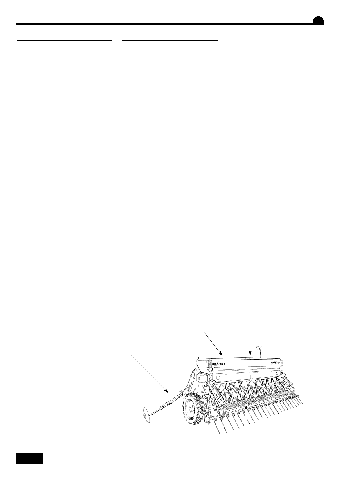
F
DANGER
l Zone de fonctionnement des traceurs
m Arbre d’agitateur en rotation
n Risque d’écrasement attelage
o Ne pas stationner sur la passerelle
l
m
n
o

5
GENERAL SAFETY REGULATIONS
Every time the tractor/machine assembly is to be
started up and used, you should ensure beforehand that it complies with current legislation on
safety at work and Road Traffic regulations.
GENERAL
1 - In addition to the instructions contained in this
manual, legislation relating to safety instructions
and accident prevention should be complied with.
2 - Warnings affixed to the machine give indica-
tions regarding safety measures to be observed
and help to avoid accidents.
3 - When travelling on public roads, abide by the
provisions of the Highway Code.
4 - Before starting work, it is essential that the
user familiarizes himself with the control and operating elements of the machine and their respective functions. When the machine is running, it may
be too late.
5 - The user should avoid wearing loose clothing
which may be caught up in the moving parts.
6 - We recommend using a tractor with a safety
cab or roll bar conforming to standards in force.
7 - Before starting up the machine and beginning
work, check the immediate surroundings, particularly for children. Make sure that visibility is adequate. Clear any persons or animals out of the
danger zone.
8 - It is strictly forbidden to transport any persons
or animals on board the machine whether it is in
operation or not.
9 - The machine should only be coupled up to the
tractor at the specially provided towing points and
in accordance with applicable safety standards.
10 - Extreme care must be taken when coupling
or uncoupling the machine from the tractor.
11 - Before hitching up the machine, ensure that
the front axle of the tractor is sufficiently weighted. Ballast weights should be fitted to the special
supports in accordance with the instructions of the
tractor manufacturer.
12 - Do not exceed the maximum axle weight or
the gross vehicle weight rating.
13 - Do not exceed the maximum authorized
dimensions for using public roads.
14 - Before entering a public road, ensure that
the protective and signalling devices (lights, reflectors, etc.) required by law are fitted and working
properly.
15 - All remote controls (cords, cables, rods,
hoses, etc.) must be positioned so that they cannot accidentally set off any manoeuvre which may
cause an accident or damage.
16 - Before entering a public road, place the
machine in the transport position, in accordance
with the manufacturer’s instructions.
17 -. Never leave the driver’s position whilst the
tractor is running.
18 - The speed and the method of operation must
always be adapted to the land, roads and paths.
Avoid sudden changes of direction under all circumstances.
19 - Precision of the steering, tractor adhesion,
road holding and effectiveness of the braking
mechanism are influenced by factors such as the
weight and nature of the machine being towed,
the front axle stage and the state of the land or
path. It is essential, therefore, that the appropriate
care is taken for each situation.
20 - Take extra care when cornering, taking
account of the overhang, length, height and
weight of the machine or trailer being towed.
21 - Before using the machine, ensure that all
protective devices are fitted and in good condition.
Damaged protectors should be replaced immediately.
22 - Before using the machine, check that nuts
and screws are tight, particularly those for attaching tools (discs, flickers, deflectors, etc.).
Tighten if necessary.
23 - Do not stand in the operating area of the
machine.
24 - Caution! Be aware of any crushing and
shearing zones on remote-controlled and particularly hydraulically-controlled parts.
25 - Before climbing down from the tractor, or
before any operation on the machine, turn off the
engine, remove the key from the ignition and wait
until all moving parts have come to a standstill.
26 - Do not stand between the tractor and the
machine until the handbrake has been applied
and/or the wheels have been wedged.
27 -. Before any operation on the machine, ensure
that it cannot be started up accidentally.
28 - Do not use the lifting ring to lift the machine
when it is loaded.
PROPER USE OF THE MACHINE
The Seed drill must only be used for tasks for
which it has been designed.
The manufacturer will not be liable for any damage
caused by using the machine for applications
other than those specified by the manufacturer.
Using the machine for purposes other than those
originally intended will be done so entirely at the
user’s risk.
Proper use of the machine also implies:
- complying with instructions on use, care and
maintenance provided by the manufacturer;
- using only original or manufacturer recommended spare parts, equipment and accessories.
The Seed drill must only be operated, maintained
and repaired by competent persons, familiar with
the specifications and methods of operation of the
machine. These persons must also be informed of
the dangers to which they may be exposed.
The user must strictly abide by current legislation
regarding:
- accident prevention;
- safety at work (Health and Safety Regulations);
- transport on public roads (Road Traffic
Regulations).
Strict compliance with warnings affixed to the
machine is obligatory.
The owner of the equipment shall become liable
for any damage resulting from alterations made to
the machine by the user or any other person,
without the prior written consent of the manufacturer.
The noise created by the machine does not
exceed 70 decibels.
HITCHING
1 -
When hitching or unhitching the machine from
the tractor, place the control lever of the hydraulic
lift in such a position that the lifting mechanism
cannot be activated accidentally.
2 - When hitching the machine to the three-point
lifting mechanism of the tractor, ensure that the
diameters of the pins or gudgeons correspond to
the diameter of the tractor ball joints.
3 - Caution! In the three-point lifting zone, there
may be a danger of crushing and shearing.
4 - Do not stand between the tractor and the
machine whilst operating the external lift control
lever.
5 - When in transport, lifting mechanism stabilizer
bars must be fitted to the machine to avoid floating and side movement.
6 - When transporting the machine in the raised
position, lock the lift control lever.
DRIVE EQUIPMENT
(Power take-off and universal drive shafts)
1 - Only use universal drive shafts supplied with
the machine or recommended by the manufacturer.
2 - Power take-off and universal drive shaft
guards must always be fitted and in good condition.
3 - Ensure that the tubes of the universal drive
shafts are properly guarded, both in the working
position and in the transport position.
Safety regulations
Risk of accident
Risk of damage to the machine
Operating tip
These symbols are used in these instructions every time recommendations are provided concerning your safety, the safety of others or the cor-
rect operation of the machine.
These recommendations must be given to all users of the machine.
GB
6
4 - Before connecting or disconnecting a universal
drive shaft, disengage the power take-off, turn off
the engine and re-move the key from the ignition.
5 - If the primary universal drive shaft is fitted with
a torque limiter or a free wheel, these must be
mounted on the machine power take-off.
6 - Always ensure that universal drive shafts are
fitted and locked correctly.
7 - Always ensure that universal drive shaft guards
are immobilized in rotation using the specially provided chains.
8 - Before engaging power take-off, ensure that
the speed selected and the direction of rotation of
the power take-off comply with the manufacturer’s instructions.
9 - Before engaging power take-off, ensure that
no persons or animals are close to the machine.
10 - Disengage power take-off when the universal
drive shaft angle limits laid down by the manufacturer are in danger of being exceeded.
11 - Caution! When power take-off has been
disengaged, moving parts may continue to rotate
for a few moments. Do not approach until they
have reached a complete standstill.
12 - On removal from the machine, rest the uni-
versal drive shafts on the specially provided supports.
13 - After disconnecting the universal drive shafts
from the power take-off, the protective cap should
be fitted to the power take-off.
14 - Damaged power take-off and universal drive
shaft guards must be replaced immediately.
HYDRAULIC CIRCUIT
1 - Caution! The hydraulic circuit is pressurized.
2 - When fitting hydraulic motors or cylinders,
ensure that the circuits are connected correctly in
accordance with the manufacturer’s guidelines.
3 - Before fitting a hose to the tractor’s hydraulic
circuit, ensure that the tractor-side and machine-
side circuits are not pressurized.
4 - The user of the machine is strongly recom-
mended to identify the hydraulic couplings between the tractor and the machine in order to
avoid wrong connection. Caution! There is a danger of reversing the functions (for example:
raise/lower).
5 - Check hydraulic hoses once a year:
. Damage to the outer surface
. Porosity of the outer surface
. Deformation with and without pressure
. State of the fittings and seals
The maximum working life for hoses is 6 years.
When replacing them, ensure that only hoses with
the specifications and grade recommended by the
machine manufacturer are used.
6 - When a leak is found, all necessary precau-
tions should be taken to avoid accidents.
7 - Pressurized liquid, particularly hydraulic circuit
oil, may cause serious injury if it comes into
contact with the skin. If the case of injury, consult
a doctor immediately. There is a risk of infection.
8 - Before any operation on the hydraulic circuit,
lower the machine, release the pressure from the
circuit, turn off the engine and remove the key
from the ignition.
MAINTENANCE
1 -
Before commencing any maintenance, servi-
cing or repair work, or before attempting to locate
the source of a breakdown or fault, it is essential
that the power take-off is disengaged, the engine
turned off and the key removed from the ignition.
2 - Check regularly that nuts and screws are not
loose. Tighten if necessary.
3 - Before carrying out maintenance work on a
raised machine, prop it up using appropriate
means of support.
4 - When replacing a working part (fertilizer
spreader blade or seed drill coulter), wear protective gloves and only use appropriate tools.
5 - To protect the environment, it is forbidden to
throw away oil, grease or filters of any kind. Give
them to specialist recycling firms.
6 - Before operating on the electric circuit, dis-
connect the power source.
7 - Protective devices likely to be exposed to wear
and tear should be checked regularly. Replace
them immediately if they are damaged.
8 - Spare parts should comply with the standards
and specifications laid down by the manufacturer.
Only use Sulky spare parts.
9 - Before commencing any electric welding work
on the tractor or the towed machine, disconnect
the alternator and battery cables.
10 - Repairs affecting parts under stress or pres-
sure (springs, pressure accumulators, etc.) should
be carried out by suitably qualified engineers with
special tools.
DANGER
l Side marker operating zone
m Rotating agitator shaft
n Risk of pinching or crushing
o Do not travel on the platform
GB
l
m
n
o

7
ALLGEMEINE SICHERHEITSVORSCHRIFTEN
Vor jeder Benutzung und Inbetriebsetzung der
Schlepper-Maschine-Einheit kontrollieren, ob sie
den Sicherheitsvorschriften und den Vorschriften
der Straßenverkehrsordnung entsprechen.
ALLGEMEINES
1 - Zusätzlich zu den in diesem Handbuch enthal-
tenen Anweisungen die Gesetzgebung bezüglich
der Sicherheits- und Unfallverhütungvorschriften
einhalten.
2 - Die auf der Maschine angebrachten
Warnungen informieren über die einzuhaltenden
Sicherheitsmaßnahmen und tragen zur
Unfallverhütung bei.
3 - Im Straßenverkehr die
Straßenverkehrsordnung einhalten.
4 - Vor Arbeitsbeginn muß sich der Benutzer
unbedingt mit den Antriebs- und
Bedienungsorganen der Maschine und ihren
jeweiligen Funktionen vertraut machen. Während
der Arbeit ist es dafür zu spät.
5 - Weite Kleidungsstücke, die in sich bewegende
Teile geraten könnten, vermeiden.
6 - Es empfiehlt sich, gemäß den gültigen Normen
einen Schlepper mit Kabine oder
Sicherheitsverstärkung zu verwenden.
7 - Vor Inbetriebsetzung und Arbeitsbeginn die
direkte Umgebung kontrollieren (Kind!). Für ausreichende Sicht sorgen! Personen oder Tiere aus
dem Maschinengefahrenbereich entfernen
(Schutzvorrichtungen!).
8 - Der Transport von Personen oder Tieren auf
der Maschine ist während der Arbeit oder beim
Fahren streng verboten.
9 - Die Maschine darf gemäß den geltenden
Sicherheitsnormen nur an den dafür vorgesehenen
Kupplungspunkten angehängt werden.
10 - Besondere Vorsicht ist beim An- und Abbau
der Maschine am Schlepper geboten.
11 - Vor Anhängen der Maschine kontrollieren, ob
der Ballast des Schleppers genügt. Die
Ballastelemente müssen gemäß den Vorschriften
des Schlepperherstellers auf den dafür vorgesehenen Haltern angebracht werden.
12 - Die maximale Achslast und das zulässige
Gesamtgewicht einhalten.
13 - Das für den Straßenverkehr maximal zu-
lässige Außenmaß einhalten.
14 - Vor Straßenbenutzung die Schutz-
vorrichtungen und Signalisierungsvorrichtungen
(Licht- und Rückstrahlelemente) anbringen und
ihre Funktion prüfen.
15 - Alle Fernsteuerungen (Seil, Kabel, Stange,
Schlauch) müssen so positioniert sein, daß sie
nicht ungewollt betätigt werden und dadurch
Unfälle oder Schäden hervorrufen können.
16 - Vor Benutzung der Straße die Maschine
gemäß Herstelleranweisungen in Transportstellung
bringen.
17 -. Fahrersitz nie bei laufender Maschine
verlassen.
18 - Fahrgeschwindigkeit und -weise müssen
immer dem Gelände, den Straßen und Wegen
angepaßt sein. Auf alle Fälle plötzliche
Richtungsänderungen vermeiden.
19 - Die Präzision der Lenkung, die Bodenhaftung
des Schleppers, die Straßenlage und die
Wirksamkeit der Bremsvorrichtungen werden
beeinflußt von Faktoren wie: Gewicht und Art der
angebauten Maschine, Belastung der Vorderachse,
Zustand des Geländes oder der Fahrbahn. Die den
Bedingungen entsprechenden
Vorsichtsmaßnahmen einhalten.
20 - Besondere Vorsicht ist in Kurven geboten.
Schwerpunktlage, Länge, Höhe und Gewicht der
Maschine oder des Anhängers berücksichtigen.
21 - Vor jeder Benutzung der Maschine kontrollie-
ren, ob alle Schutzvorrichtungen angebracht und
in gutem Zustand sind. Bei Beschädigung sofort
austauschen.
22 - Vor jeder Benutzung kontrollieren, ob alle
Schrauben und Muttern fest angezogen sind, insbesondere die, mit denen die Geräte befestigt sind
(Scheiben, Paletten, Schirme...). Notfalls anziehen.
23 - Sich nicht im Manövrierbereich der Maschine
aufhalten.
24 - Vorsicht! Auf den Fernsteuerungsorganen,
insbesondere auf denen mit hydraulischem
Regelkreis, kann es Stauch- und Abscherzonen
geben.
25 - Vor Verlassen des Schleppers oder vor jedem
Eingriff auf der Maschine Motor abschalten,
Zündschlüssel abziehen und völligen Stillstand
aller bewegten Teile abwarten.
26 - Sich nicht zwischen Schlepper und Maschine
aufhalten, ohne zuvor die Parkbremse angezogen
und/oder Keile unter die Räder gelegt zu haben.
27 - Vor jedem Eingriff an der Maschine kontrol-
lieren, ob diese nicht ungewollt in Betrieb gesetzt
werden kann.
28 - Die Aufhängöse nicht zum Heben der gefüll-
ten Maschine benutzen.
BESTIMMUNGSGEMÄßE VERWENDUNG DER
MASCHINE
Die Drillmaschine darf nur für die Arbeiten einge-
setzt werden, für die sie geplant ist.
Bei Beschädigung der Maschine infolge einer
nicht vom Hersteller spezifizierten Benutzung ist
dieser nicht haftbar.
Jede nicht der ursprünglichen Bestimmung der
Maschine entsprechende Benutzung erfolgt auf
Rechnung und Gefahr des Benutzers.
Die bestimmungsgemäße Verwendung der
Maschine setzt ebenfalls voraus:
- die Einhaltung der vom Hersteller verordneten
Benutzungs-, Wartungs- und
Instandsetzungsvorschriften,
- die ausschließliche Verwendung von
Originalersatzteilen, Originalausrüstungen und
Originalzubehör oder von Teilen, die vom Hersteller
empfohlen sind.
Die Drillmaschine darf nur von kompetenten, mit
den technischen Daten und
Benutzungsanweisungen der Maschine vertrauten
Personen benutzt, gewartet und repariert werden,
die über die Risiken informiert sind, denen sie ausgesetzt sein könnten.
Streng die gültige Reglementierung einhalten
bezüglich:
- der Unfallverhütung,
- der Arbeitssicherheit (Arbeitsgesetzbuch)
- des Straßenverkehrs (Straßenverkehrsordnung).
Die auf der Maschine angebrachten Warnungen
berücksichtigen.
Der Hersteller haftet nicht für Schäden, die durch
Abänderungen entstehen, die vom Benutzer selbst
oder von Dritten ohne schriftliche Genehmigung
an der Maschine vorgenommen wurden.
Das von der Maschine hervorgerufene Geräusch
liegt unter 70 Dezibel.
ANHÄNGUNG
1 - Beim An- und Abkuppeln der Maschine am
Schlepper, den Steuerhebel des
Hydraulikkrafthebers so stellen, daß der Hub-vorgang nicht unerwartet ausgelöst werden kann.
2 - Beim Anhängen der Maschine am
Dreipunktkraftheber des Schleppers darauf achten, daß die Spindel- oder Zapfendurchmesser
dem Durchmesser der Schlepperkugelgelenke
entsprechen.
3 - Vorsicht! Im Dreipunkt-Hubbereich bestehen
Stauch- und Abscherrisiken!
4 - Sich bei Betätigung des äußeren Kraftheber-
Steuerhebels nicht zwischen Schlepper und
Maschine aufhalten.
5 - Beim Transport muß die Maschine durch die
Versteifungsstreben des Krafthebers zur
Vermeidung von Unwucht und seitlicher
Pendelung stabilisiert werden.
6 - Beim Transport der Maschine in angehobener
Stellung den Kraftheber-Steuerhebel blockieren.
Sicherheitsvorschriften
Verletzungsgefahr
Gefahr der Beschädigung der Maschine
Hinweis zur Erleichterung der Arbeit
In der Anweisung werden diese Zeichen in Verbindung mit Empfehlungen für Ihre Sicherheit und der anderer sowie die gute Funktion der
Maschine verwendet.
Jeder Benutzer dieser Maschine muß diese Vorschriften genau kennen.
D
8
ANTRIEBSORGANE
(Zapfwelle und Gelenkwellen-Antrieb)
1 - Nur die mit der Maschine gelieferte oder vom
Konstrukteur empfohlene Gelenkwelle verwenden.
2 - Die Schutzvorrichtungen der Zapfwellen und
Gelenkwellen müssen immer angebracht und in
gutem Zustand sein.
3 - Auf die richtige Überlappung der
Gelenkwellenrohre sowohl in Arbeits- als auch in
Transportstellung achten.
4 - Vor Anschließen oder Abziehen einer
Gelenkwelle die Zapfwelle auskuppeln, den Motor
abschalten und den Zündschlüssel abziehen.
5 - Ist die Primärkardanwelle mit einem
Drehmomentbegrenzer oder einer
Freilaufkupplung ausgestattet, müssen diese unbedingt auf der Zapfwelle der Maschine montiert
sein.
6 - Immer auf die korrekte Montage und
Verriegelung der Kardanantriebe achten.
7 - Immer darauf achten, daß die
Schutzvorrichtungen der Gelenkwellen mit den
dafür vorgesehenen Ketten gegen Verdrehen gesichert sind.
8 - Vor Kuppeln der Zapfwelle prüfen, ob die
gewählte Drehzahl und die Drehrichtung der
Zapfwelle den Vorschriften des Herstellers entsprechen.
9 - Vor Kuppeln der Zapfwelle kontrollieren, ob
sich keine Personen oder Tiere in Nähe der
Maschine befinden.
10 - Die Zapfwelle auskuppeln, wenn Gefahr bes-
teht, daß die vom Hersteller vorgeschriebenen
Grenzen des Gelenkwellenwinkels überschritten
werden.
11 - Vorsicht! Nach Auskuppeln der Zapfwelle
können Teile der Maschine noch einige Zeit
nachlaufen. Sich ihnen nie vor völligem Stillstand
nähern.
12 - Bei Abbau der Maschine die Gelenkwellen
auf den dafür vorgesehenen Haltern ablegen.
13 - Nach Abziehen der Gelenkwelle von der
Schlepperzapfwelle muß diese mit ihrer
Schutzkappe bedeckt werden.
14 - Schadhafte Schutzvorrichtungen der
Zapfwelle und der Gelenkwelle müssen sofort ausgewechselt werden.
HYDRAULIKLEITUNG
1 -
Vorsicht! Die Hydraulikleitung steht unter
Druck.
2 - Bei Montage von Zylindern oder
Hydraulikmotoren auf den korrekten Anschluß
gemäß Anweisungen des Herstellers achten.
3 - Vor Anschluß eines Schlauches an der
Hydraulikleitung des Schleppers dafür sorgen, daß
die schlepper- und maschinenseitigen Leitungen
nicht unter Druck stehen.
4 - Dem Benutzer der Maschine wird zur
Vermeidung falscher Anschlüsse dringend geraten,
die Kennzeichnungen auf den
Hydraulikanschlüssen zwischen Schlepper und
Maschine zu beachten, da sonst die Gefahr einer
Funktionsumkehrung besteht. (z.B.:
Heben/Senken).
5 - Einmal im Jahr die Hydraulikschläuche kontrol-
lieren auf:
. Beschädigung der Außenschicht
. Porosität der Außenschicht
. Verformung ohne Druck und unter Druck
. Zustand der Verbindungen und Dichtungen.
Die maximale Benutzungsdauer der Schläuche ist
6 Jahre. Beim Auswechseln darauf achten, daß
nur Schläuche verwendet werden, deren
Eigenschaften und Qualität den Vorschriften des
Maschinenkonstrukteurs entsprechen.
6 - Bei Feststellung einer undichten Stelle alle
Vorsichtsmaßnahmen zur Unfallverhütung treffen.
7 - Eine unter Druck stehende Flüssigkeit, insbe-
sondere das Öl der Hydraulikleitung, kann die Haut
durchdringen und schwere Verletzungen verursachen! Bei Verletzungen sofort Arzt konsultieren;
Infektionsgefahr!
8 - Vor jedem Eingriff in die Hydraulikanlage
Maschine ablassen, Anlage drucklos schalten,
Motor abstellen und Zündschlüssel abziehen.
WARTUNG
1 - Vor Instandsetzungs-, Wartungs- oder
Reparaturarbeiten sowie bei Ermitteln einer
Pannen- oder Betriebsstörungsquelle muß die
Zapfwelle ausgekuppelt, der Motor abgeschaltet
und der Zündschlüssel abgezogen sein.
2 - Regelmäßig kontrollieren, ob Schrauben und
Muttern fest angezogen sind. Notfalls anziehen.
3 - Vor Wartung einer Maschine in angehobener
Stellung diese mit einem geeigneten Mittel abstützen.
4 - Beim Austausch eines Funktionsteiles
(Schaufel bei Streuern oder Schare bei
Drillmaschinen) Schutzhandschuhe tragen und nur geeignete Werkzeuge
benutzen.
5 - Zum Schutz der Umwelt ist es verboten, Öl,
Fett und Filter jeder Art wegzuwerfen oder auszugießen. Sie sind von darauf spezialisierten
Unternehmen zu entsorgen.
6 - Vor Eingriff an der elektrischen Leitung die
Stromzufuhr unterbrechen.
7 - Verschleiß ausgesetzte Schutzvorrichtungen
müssen regelmäßig kontrolliert werden. Sie sofort
austauschen, wenn schadhaft.
8 - Ersatzteile müssen den vom Konstrukteur fest-
gelegten Normen und Kennwerten entsprechen.
Nur Sulky-Ersatzteile verwenden!
9 - Vor Elektroschweißarbeiten am Schlepper oder
der angehängten Maschine die Kabel des
Wechselstromgenerators und der Batterie abziehen.
10 - Reparaturen an Organen, die unter Spannung
oder Druck stehen (Federn, Druckspeicher, usw...)
setzen eine ausreichende Qualifikation voraus und
erfordern Werkzeuge; sie dürfen daher nur von
qualifiziertem Personal durchgeführt werden.
D
GEFAHR
l Arbeitsbereich der Spurreißer
m Rührwerkwelle dreht sich
n Stauchgefahr Kupplung
o Sich nicht auf dem Ladesteg aufhalten
l
m
n
o

9
Pages
MISE EN ROUTE
SOMMAIRE
Français
13
12-13
14-15
14-15
• A Préparation de la machine
• B Manutention
• C Attelage
• D Aplomb
Pages
REGLAGES
20-29
30-33
34-35
36-37
• A Réglage du débit
• B Traceurs latéraux
• C Réglage du terrage
• D Réglage de la herse de
recouvrement
Pages
ENTRETIEN
53
52-53
53
54-55
56-57
58-59
• A Entretien
• B Graissage
• C Vérification
• D Distribution
• E Caractéristiques techniques
• F Positions Autocollants
14-15
16-17
16-17
18-19
• E Béquille
• F Hydraulique
• G Electrique/Electronique
• H Remplissage de la trémie
Pages
TABLEAUX DE REGLAGE
66
67-95
• A Rappel pré-réglages
• B Tableaux de débit
Lire attentivement la notice avant l’utilisation. Comprendre son épandeur
c’est mieux l’utiliser. En français suivre le symbole.
F
38-39
40-49
50-51
50-51
• E Réglage des effaceurs
de traces
• F Dispositif de marquage
• G Débrayage 1/2 semoir
• H Vidange de la trémie
5
4
1
2
3
Pages
EQUIPEMENTS
60-61
60-61
62-63
64-65
• A Limiteur de profondeur
• B Soc uniband
• C Modulation MS
• D Compteur d'ha

10
Read the manual carefully before use. Better understanding
means better and safer spreading. For English follow the symbol.
GB
CONTENTS
English
Pages
START-UP
13
12-13
14-15
14-15
• A Preparing the machine
• B Handling
• C Hitching
• D Vertical setting
Pages
SETTINGS
20-29
30-33
34-35
36-37
• A Setting the flow
• B Markers
• C Depth control
• D Adjusting the covering
harrow
Pages
MAINTENANCE
53
52-53
53
54-55
56-57
58-59
• A Maintenance
• B Lubrication
• C Checks
• D Distribution
• E Technical specifications
• F Sticker positions
14-15
16-17
16-17
18-19
• E Parking support
• F Hydraulics
• G Electrics/Electronics
• H Filling the seed box
Pages
SETTING CHARTS
66
66-95
• A Pre-setting reminder
• B Seeding rate charts
38-39
40-49
50-51
50-51
• E Adjusting the track
eradicators
• F Tramlining
• G Disengaging half of the
seed drill
• H Emptying the seed box
Pages
ACCESSORIES
60-61
60-61
62-63
64-65
• A Depth limiter
• B Uniband share
• C MS flow rate modulation
• D Areameter

11
VERZEICHNIS
Deutsch
Seite
INBETRIEBSETZUNG
13
12-13
14-15
14-15
14-15
• A Vorbereitung der Maschine
• B Handhabung
• C Anbau
• D Senkrechtstellung
• E Stütze
Seite
EINSTELLUNGEN
20-29
30-33
34-35
36-37
• A Saatmengeneinstellung
• B Spurreißer
• C Schardruckeinstellung
• D Einstellung des
Saatstriegels
Seite
WARTUNG
53
52-53
53
54-55
56-57
58-59
• A Wartung
• B Schmierung
• C Prüfung
• D Verteilung
• E Technische Daten
• F Sicherheitsaufkleber
16-17
16-17
18-19
• F Hydraulik
• G Elektrischer/
Elektronischer Anschluß
• H Füllen des Saatkastens
Seite
EINSTELLTABELLEN
66
66-95
• A Zur Erinnerung: Voreinstellungen
• B Sämengentabellen
Anweisung vor Benutzung sorgfältig durchlesen. Die Düngerstreuer
verstehen, heißt sie besser benutzen. Die deutsche Fassung ist mit
gekennzeichnet.
D
38-39
40-49
50-51
50-51
• E Einstellung der
Spurlockerer
• F Fahrgassenanlage
• GAbschalten 1/2 Drillmaschine
• H Saatkastenentleerung
5
4
1
2
3
Seite
AUSRÜSTUNGEN
60-61
60-61
62-63
64-65
• A Sätiefenbegrenzer
• B Uniband-Schar
• C Streumengen-Modulation MS
• D Hektarzähler
12
Mise en route
Start-up
Inbetriebsetzung
Ne lever le semoir MASTER 3
qu’avec la trémie vide.
Assurez-vous qu’il n’y ait personne autour de la machine
lors de la manipulation.
Do not lift the MASTER 3
unless the seed box is empty.
Make sure that there is noone around the machine
during handling operations
Die MASTER 3-Drillmaschine
nur mit leerem Saatkasten
heben.
Sich vergewissern, daß sich
dabei niemand in Nähe der
Maschine aufhält.
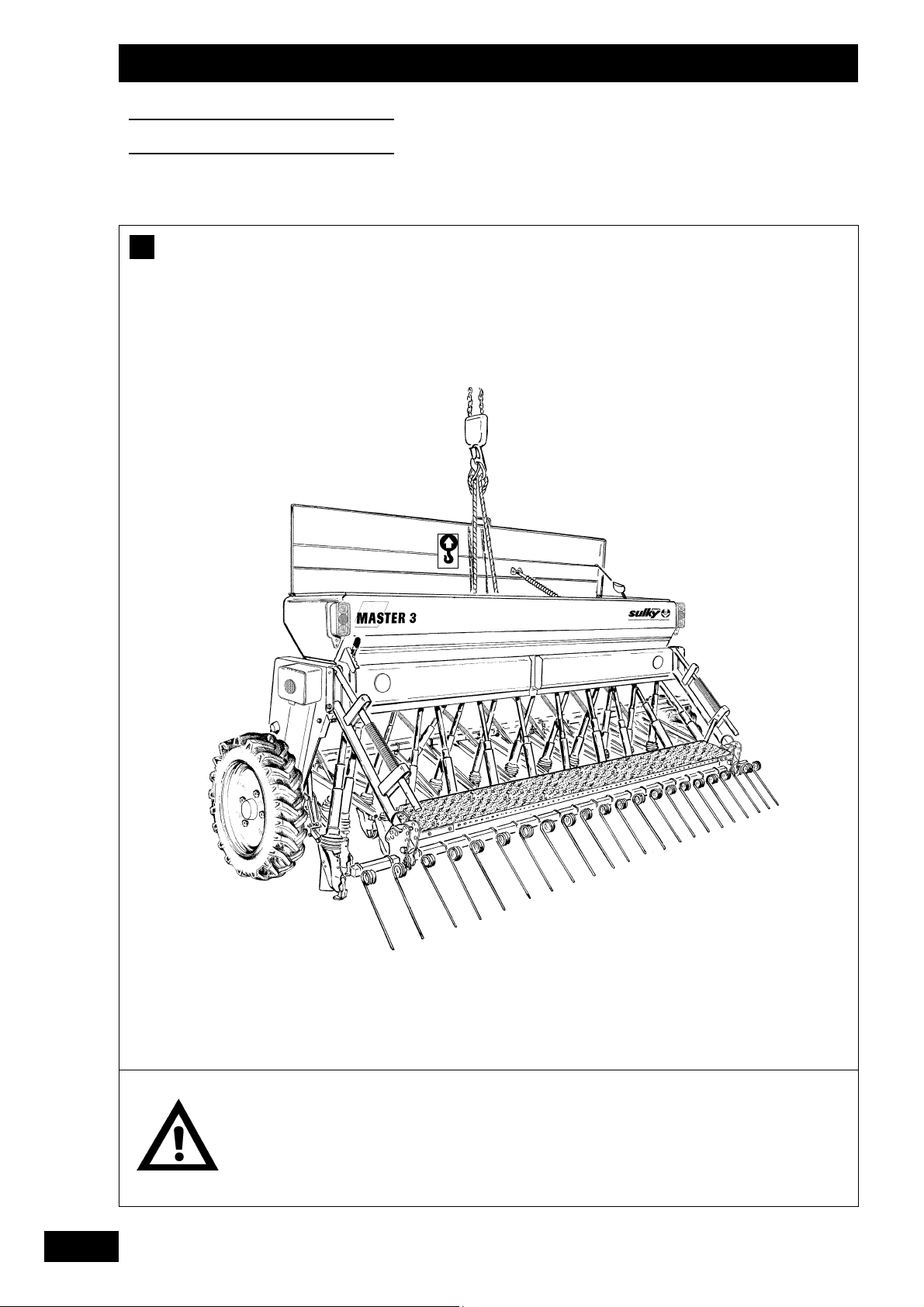
B

13
Vorbereitung der Maschine
• Bei Lieferung prüfen, ob das Gerät komplett geliefert
wurde.
• Prüfen, ob sich kein Fremdkörper im Saatkasten befindet.
• Die MASTER 3 nur für Arbeiten benutzen, für die sie bestimmt ist.
• Prüfen, ob die Maschine nicht während des Transports
beschädigt worden ist und kein Teil fehlt. Nur bei.
Abnahme formulierte Reklamationen können berücksichtigt werden.
Eventuelle Schäden vom Spediteur feststellen lassen.
Im Zweifelsfall Ihren Verkäufer informieren.
Handhabung
• Die dafür im Saatkasten vorgesehene Öse benutzen.
- Drillmaschine ohne Saategge und Vorauflaufmarkierer
heben.
- Vorsichtig arbeiten, damit der Deckel nicht beschädigt
wird.
GB
Preparing the machine
• On delivery, check that the seed drill is complete.
• Ensure that there are no foreign bodies in the seed box.
•The MASTER 3 should only be used for tasks for which it
has been designed.
• Check that the machine has not suffered any damage
during transport and that no parts are missing.
Only claims made on taking delivery of the machine will be
considered. Any damage should be reported to the delivery man.
If in doubt or in the event of any complaint, please contact
your dealer.
Handling
• Use the specially provided ring in the centre of the seed
box.
- Lift the seed drill without the covering harrow and rear
marker.
- Handle with care to avoid damage to the cover.
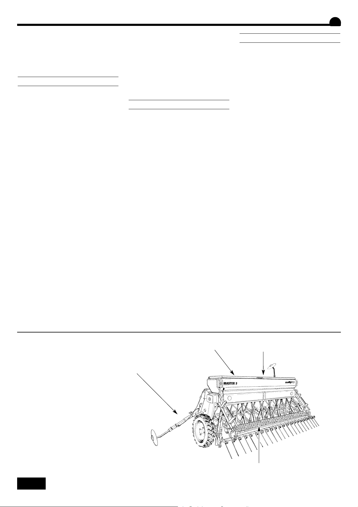
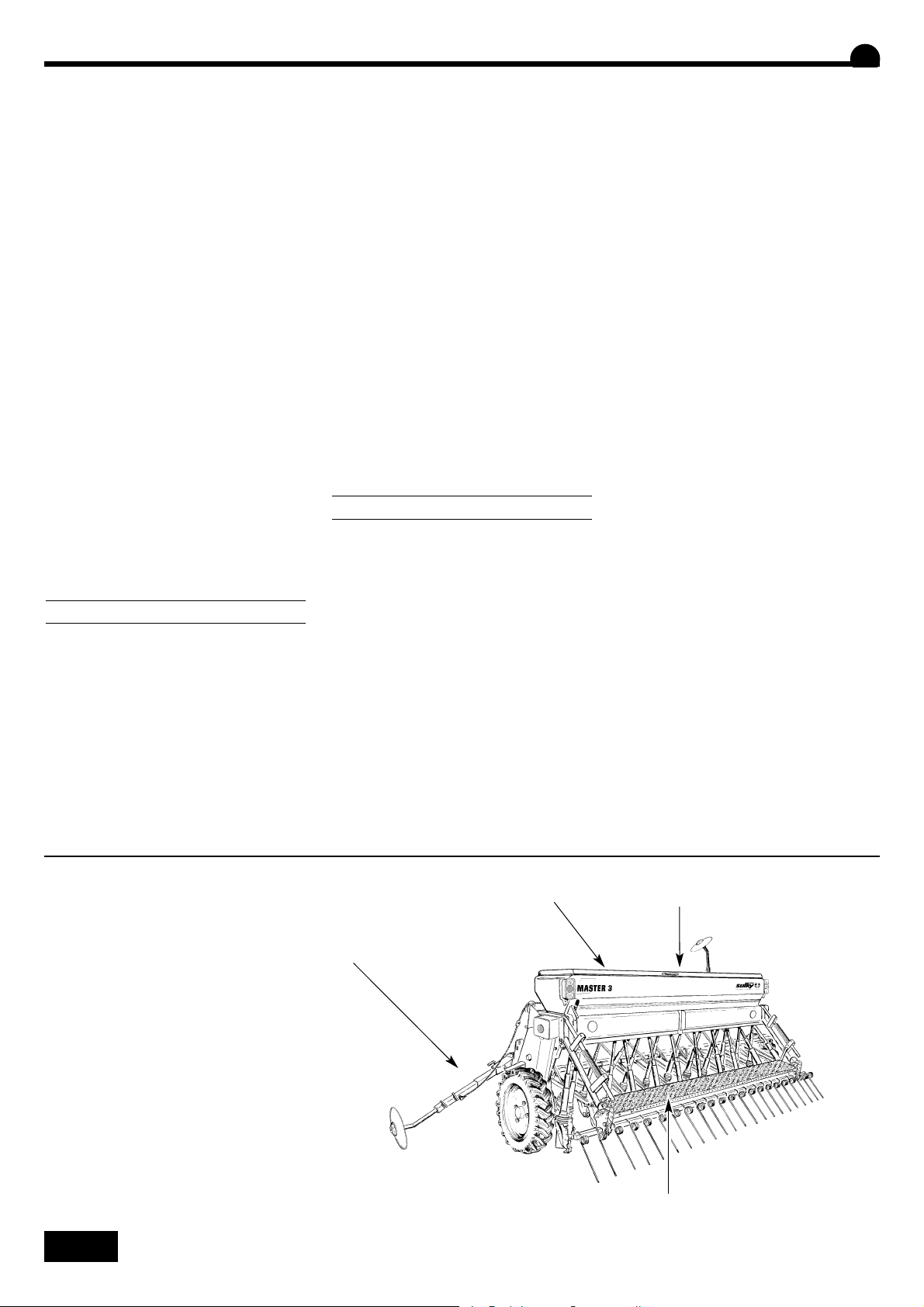
Préparation de la machine
• Au moment de la livraison, vérifier que le semoir est complet.
• Assurez-vous qu'il n'y ait pas de corps étrangers dans la
trémie.
•Le MASTER 3 ne doit être utilisé que pour les travaux
pour lesquels il a été conçu.
• Vérifier que la machine n’a subi aucun dommage en cours
de transport et qu’il ne manque aucune pièce.
Seules les réclamations formulées à réception de la
machine pourront être prises en considération.
Faire constater d’éventuels dégâts par le transporteur.
En cas de doute ou de litige, adressez-vous à votre revendeur.
Manutention
• Utiliser l’anneau au centre prévu à cet effet.
- lever le semoir, sans les équipements herse de recouvrement et jalonneur arrière.
- manœuvrer avec précaution afin d’éviter d’endommager
le couvercle.
F
A
B
A
B
A
B
1
D
Mise en route
Start-up
Inbetriebsetzung
14
Mise en route
Start-up
Inbetriebsetzung
Respecter l’aplomb de la
machine au travail.
Ne pas oublier de retirer la
béquille avant de travailler.
Check the vertical setting of
the machine before working.
Do not forget to remove the
parking support before working.
Senkrechtstellung der
Maschine bei der Arbeit
einhalten.
Nicht vergessen, Stütze vor
Arbeitbeginn zu entfernen.
D
C
E

15
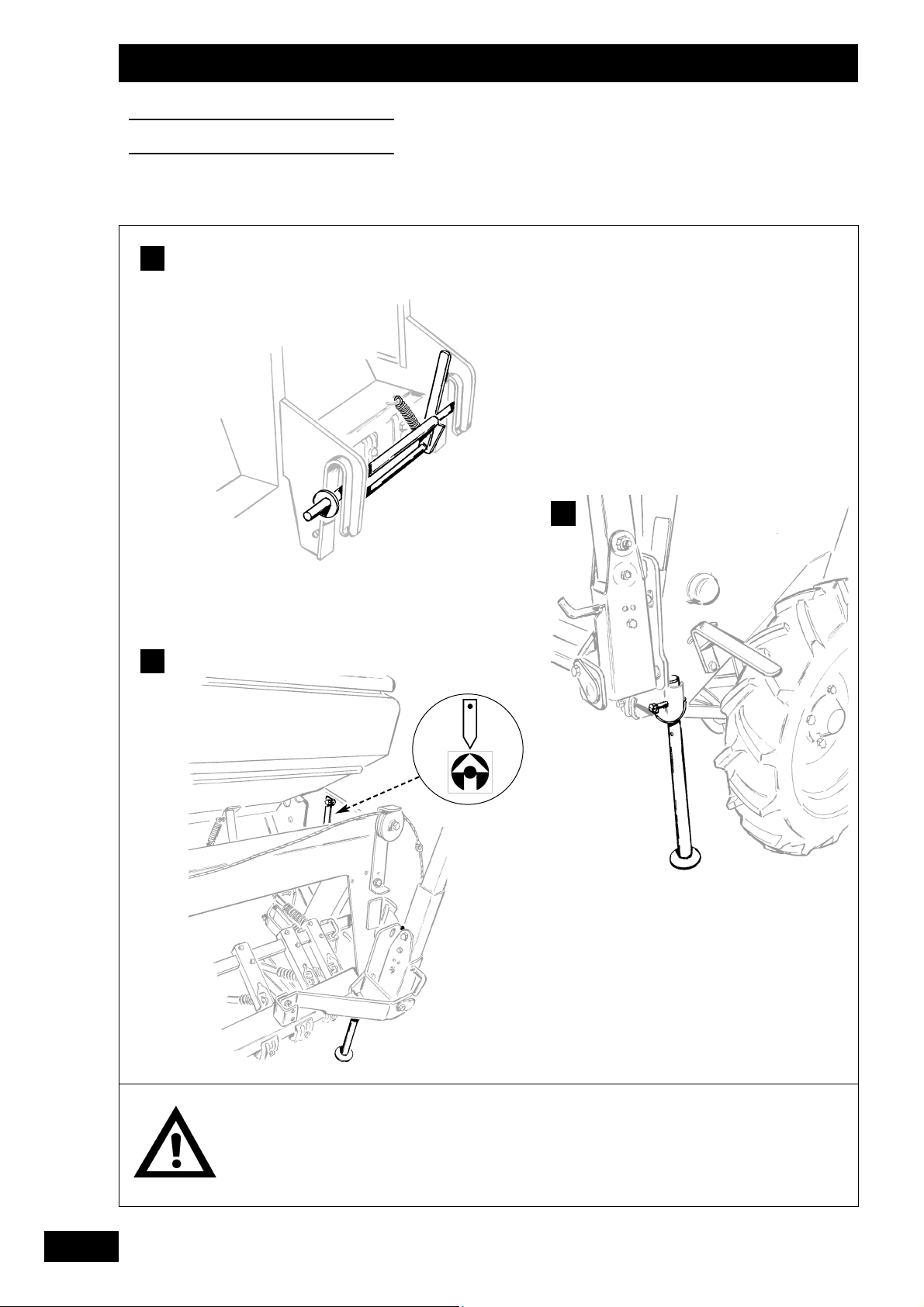
Anbau
• Der mit einer Pendelausgleich-Schnellkupplung ausgerüs-
tete Sulky MASTER 3 kann angebaut werden:
- entweder direkt an den Schlepper,
- oder an ein Bodenbearbeitungsgerät.
•Der Positionierungsbolzen muß nach unten gedreht sein,
damit sich die Kupplungsstange nicht drehen kann.
•Wenn die Drillmaschine in Arbeitsstellung ist, muß der
Hydraulikkraftheber des Schleppers immer völlig gesenkt
und weichgelagert sein.
Senkrechtstellung
• Gerät auf horizontalen Boden stellen.
• Senkrechtstellung mittels Schlepperdreipunkt regeln,
wobei der Kontrollpfeil auf der linken Seite der
Drillmaschine unter dem Saatkasten als Hilfe dient.
Stütze
• Bevor die Maschine auf den Boden gestellt und
abgehängt wird, Stütze anbringen.
GB
Hitching
• Equipped with an automatic floating hitch, the SULKY
MASTER 3 seed drill may be hitched up:
- directly to the tractor,
- or to a cultivating implement.
•The welded pin should be pointing downwards to prevent
the drawbar rotating.
•When the drill is in the working position, the tractor's
hydraulic lift system should always be fully lowered and in
the floating position.
Vertical setting
• Lay the machine on horizontal ground.
•Adjust the vertical setting with the top link of the tractor
whilst referring to the arrow on the left-hand side of the
drill beneath the seed box.
Parking support
• Before laying the machine on the ground and unhitching
it, fit the parking support.
Attelage
• Equipé d'un attelage automatique oscillant, le semoir
SULKY MASTER 3 peut être attelé :
- soit directement sur le tracteur,
- soit sur un outil de travail du sol.
•Pour empêcher la barre d'attelage de tourner, le plot de
positionnement doit être tourné vers le bas.
• En position de travail du semoir, le relevage hydraulique
du tracteur doit toujours être abaissé à fond et flottant.
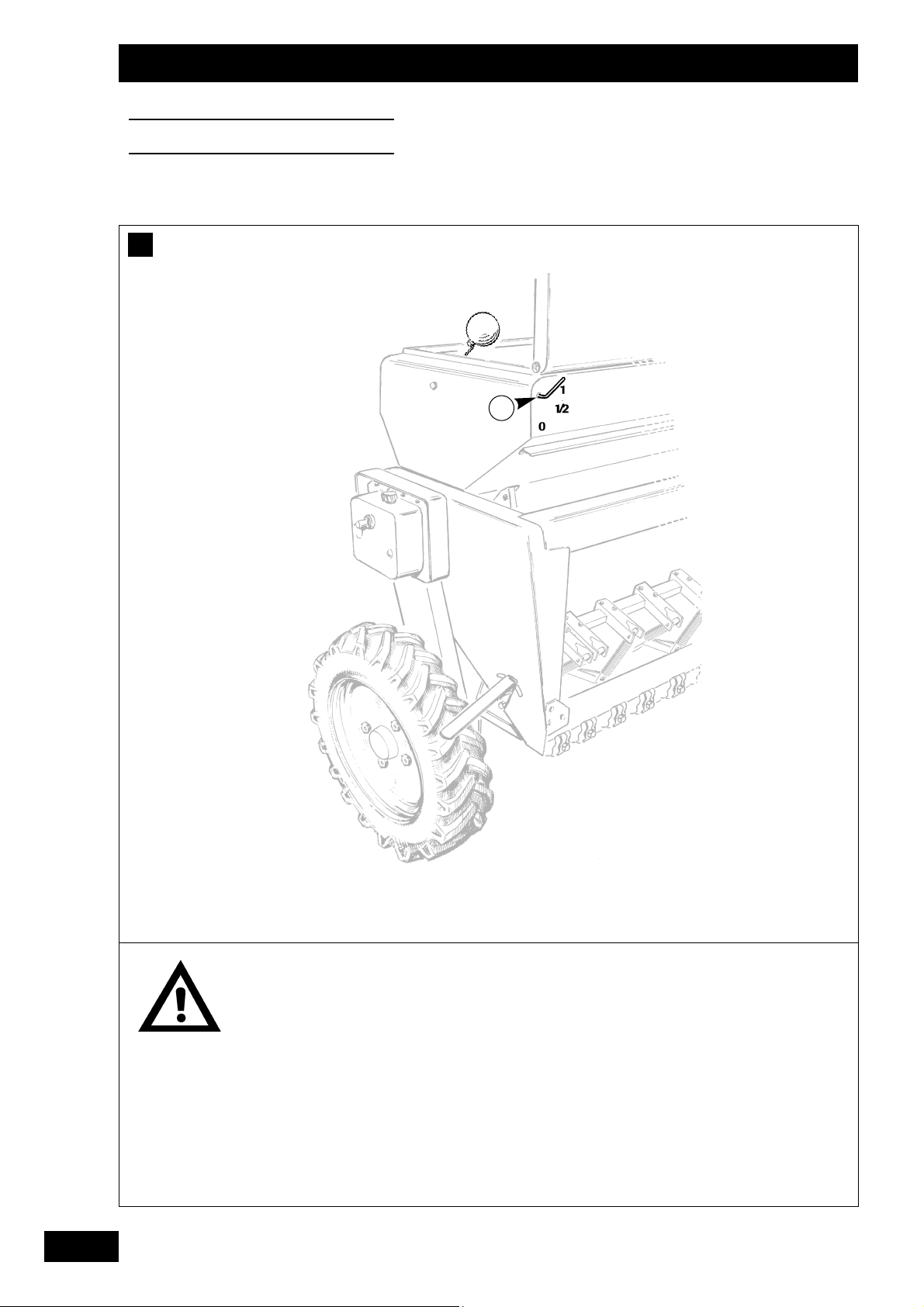
Aplomb
• Poser l'appareil sur un sol horizontal.
• Règler l'aplomb à l'aide du 3ème point du tracteur en
vous aidant de la flèche de contrôle qui est fixée côté
gauche du semoir sous la trémie.
Béquille
• Avant de poser la machine au sol et de la dételer, mettre
la béquille en position.
F
C
D
C
D
C
D
D
Mise en route
Start-up
Inbetriebsetzung
E
E
E
1
-
1
+
16
Mise en route
Start-up
Inbetriebsetzung
Il est recommandé de réali-
ser l’alimentation directement depuis la batterie pour
éviter toute microcoupure.
Veillez à garder propre la
prise hydraulique Push Pull.
We recommend that the unit
is connected directly to the
battery to ensure a constant
power supply.
Make sure that the hydraulic
push-pull connector is kept
clean.
Wir empfehlen eine Direktversorgung ab Batterie zur
Vermeidung von Mikroabschaltungen.
Push-Pull-Hydraulikstecker
sauber halten.
F
G

17
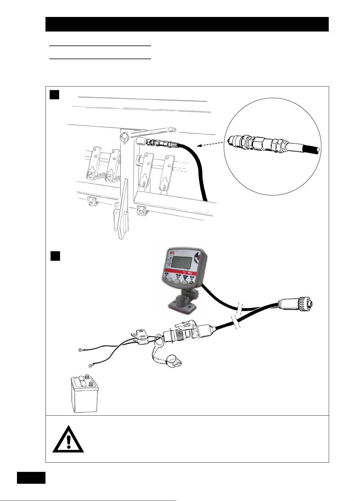
Hydraulik
• Die Hydraulikleitung des MASTERS 3 erfordert nur ein
einfachwirkendes Ventil:
- Funktion der Spurreißer
- Funktion der Fahrgasseneinrichtung nach und vor
Pflanzenaufgang (Sonderausrüstung).
Elektrischer/Elektronischer Anschluß
• Das Steuersystem der Fahrgassenschaltung erfordert eine
Gleichstromversorgung von 12 Volt (Pol+ und Markierung).
ZUSÄTZLICHE INFORMATIONEN ÜBER
DAS ELEKTRONIKGERÄT
IM HANDBUCH
MEDION
GB
Hydraulics
• The MASTER 3's hydraulic circuit only requires a single-
acting valve:
- Marker operation
- Post and pre-emergence tramlining (optional)
Electrics/Electronics
• The tramline control system requires a 12 V DC power
supply (+ and - poles identified).
ADDITIONAL INFORMATION ON THE
ELECTRONIC UNIT IS CONTAINED IN THE
MEDION MANUAL
Hydraulique
• Le circuit hydraulique du MASTER 3 ne nécessite qu'un
simple effet :
- Fonctionnement des traceurs.
- Fonctionnement du jalonnage post et pré levée (option).
Electrique / Electronique
• Le système de commande de jalonnage nécessite une ali-
mentation en 12 volts continu. (pôles + et - repérés).
INFORMATIONS COMPLEMENTAIRES
SUR LE BOITIER ELECTRONIQUE DANS
LE MANUEL
MEDION
F
F
F
F
D
Mise en route
Start-up
Inbetriebsetzung
G
G
G
18
H
Mise en route
Start-up
Inbetriebsetzung
Attention à la rotation de
l'arbre d'agitateur.
Vérifier qu'aucun corps
étranger ne se trouve dans la
trémie.
Il est conseillé de ne pas
laisser de graines à l'intérieur de la trémie afin d'éviter d'éventuels dégâts causés par les rongeurs.
Il est formellement interdit
de monter sur le semoir pendant le travail.
La charge maximum est de
300 kg.
Beware of the rotating agitator shaft.
Check that there are no
foreign bodies in the seed
box.
It is recommended not to
leave grain inside the seed
box to avoid possible damage by rodents.
It is strictly forbidden to
stand on the drill when operating.
The maximum capacity is
300 kg.
Prüfen, ob sich keine Fremdkörper im Saatkasten
befinden.
Keine Körner im Saatkasten
lassen, um eventuelle Beschädigungen durch Nagetiere zu vermeiden.
Während der Arbeit nicht in
den Saatkasten greifen rotierende Rührwelle.
Es ist strengstens untersagt
während des Einsatzes auf
die Drillmaschine zu steigen.
Höchstlast: 300 kg.
1

19
Füllen des Saatkastens
a) Vor dem Füllen
• Prüfen, ob sich kein Fremdkörper im Saatkasten befindet
(Etikett, Bindfaden, etc...).
• Alle nicht verwendeten Auslaufschieber schließen.
b) Beim Füllen
• Drillmaschine auf den Boden setzten.
•Ladesteg zum besseren Laden benutzen.
• Anmerkung: Sich bei Einsatz der Drillmaschine nicht auf
dem Ladesteg aufhalten.
c) Saatgutstand
• Ein Zeiger bewegt sich vor einer Meßskala und zeigt
ständig den Saatgutstand im Kasten an.
GB
Filling the seed box
a) Before loading
• Check that there are no foreign bodies in the seed box
(labels, string, etc.).
• Close off all distribution shutters which are not in use.
b) During loading
• Lay the seed drill on the ground.
• Use the platform for easier loading.
• Note: Do not stand on this platform while the seed drill is
in operation.
c) Seed level
• A pointer provides a permanent indication of the grain
level in the seed box.
Remplissage de la trémie
a) Avant le chargement
• Vérifier qu'aucun corps étranger ne se trouve dans la tré-
mie (étiquette, ficelle etc.).
• Fermer toutes les trappes de distribution qui ne servent
pas.
b) Au chargement
• Poser le semoir au sol.
• Utiliser la passerelle pour améliorer le chargement.
• Remarque : ne pas stationner sur cette passerelle, semoir
au travail.
c) Niveau de semence
• Une aiguille se déplace devant un secteur gradué et
indique en permanence le niveau de grain dans la trémie.
F
H
H
H
D
Mise en route
Start-up
Inbetriebsetzung
20
A
Suivre les indications de
réglage.
Follow the setting
indications.
Einstellanweisungen
befolgen.
Réglages
Settings
Einstellungen
1
0
2
1
1)
2)
2
3

21
Saatmengeneinstellung
a) Einstellung der Verteilung (vgl. Kapitel 5 bezüglich der
Einstellwerte)
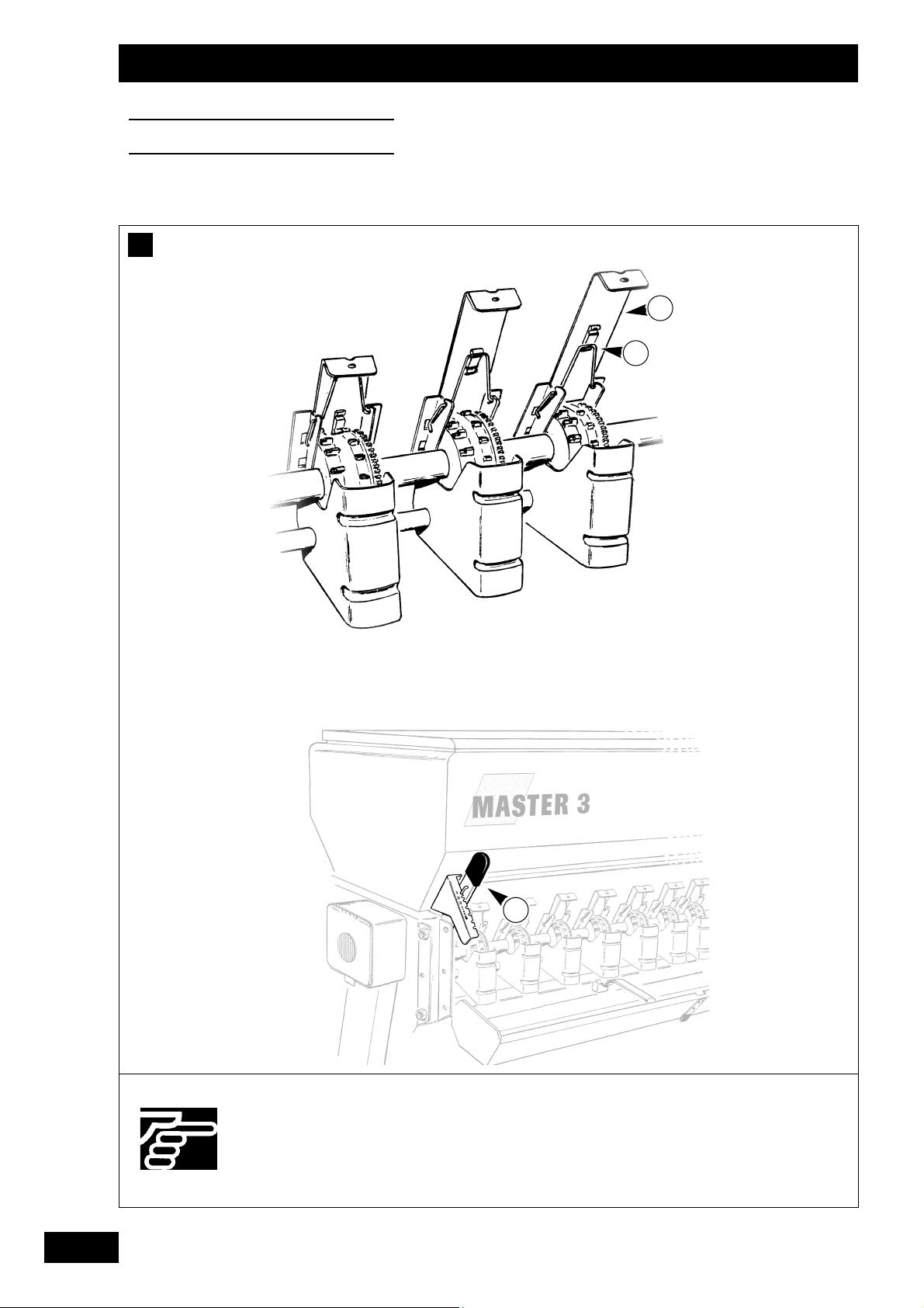
1) Auslaufschieber
• Schieber gemäß Empfehlungen heben oder senken.
Feder
in die entsprechende Nut einrasten.
• Der Schieber hat 3 Stellungen.
• Markierung 0 . Geschlossen (z.B. Aussaat alle 2 Reiher)
1 . Kleine Körner > 8 kg/ha
2 . Großes Saatgut.
2) Bodenklappe
• Den Hebel auf der rechten Seite leicht verschieben und
auf die entsprechende Kerbe stellen.
• Markierung 1 . Getreide, Raps.
2 .
3 .
4 . Erbsen für Konserven
5 . Erbsen
6 . Pferdebohnen
Max . Untere Stellung, Entleerung
• Das Korn vorzugsweise mit dem Nockenrad begleiten,
indem die Bodenklappe möglichst stark angezogen wird
(z. B.: Markierung 1 für Weizen, Gerste).
Sollte jedoch ein ständiger Kornauswurf aus der Verteilung
festgestellt werden, den Hebel eine Kerbe höher stellen als
empfohlen (B.: Markierung 2 für Weizen, Gerste).
GB
Setting the flow
a) Setting the distribution (see section 5 for the setting
values)
1) Distribution shutter
• Raise or lower the shutter as recommended. Insert the
spring into the corresponding catch.
• into the corresponding catch.
• Setting 0 . Closed (sowing one row in two, for instance)
1 . Small grain > 8 kg/ha
2 . Large grain.
2) Baffle plate
• Move lever slightly to the right and set to the appro-
priate mark.
• Setting 1 . Cereal, Rape.
2 .
3 .
4 . Canning peas
5 . Peas
6 . Field beans
Max . Bottom position, Emptying
•The aim is to have the grain metered out by the feeding rol-
ler by keeping the baffle plate as tightly closed as possible
(e.g. setting 1 for wheat and barley).
However, if you notice a constant projection of grain from the
distribution system, set the lever one mark higher than the
recommendation (e.g. setting 2 for wheat and barley).
Réglage du débit
a) Réglage de la distribution (voir chapitre 5 pour les
valeurs de réglage)
1) Trappe de distribution
• Lever ou baisser la trappe en fonction des recomman-
dations. Encliqueter le ressort dans l’encoche correspondante.
• La trappe dispose de 3 positions
• Repère 0 . Fermé (semi 1 rang sur 2 par exemple)
1 . Petites graines > 8 kg/ha
2 . Grosses graines
2) Clapet de fond
• Déplacer légèrement le levier sur la droite et mettre au
cran correspondant.
• Repère 1 . Céréales, Colza.
2 .
3 .
4 . Pois de conserve
5 . Pois
6 . Féverole
Maxi . Position basse, Vidange
• Il faut rechercher à accompagner la graine avec l'ergot en
resserrant le plus possible le clapet de fond (ex: repère 1
pour blé, orge).
Toutefois, si vous observez des projections de graines de la
distribution en permanence, placer le levier au cran supérieur
par rapport à la préconisation (ex: repère 2 pour blé, orge).
Réglages
Settings
Einstellungen
F
A
A
A
D
2
22
Réglages
Settings
Einstellungen
Suivre les indications de
réglage.
Follow the setting
indications.
Einstellanweisungen
befolgen.
3)
4)
a
b
1
2
4
5
3

23
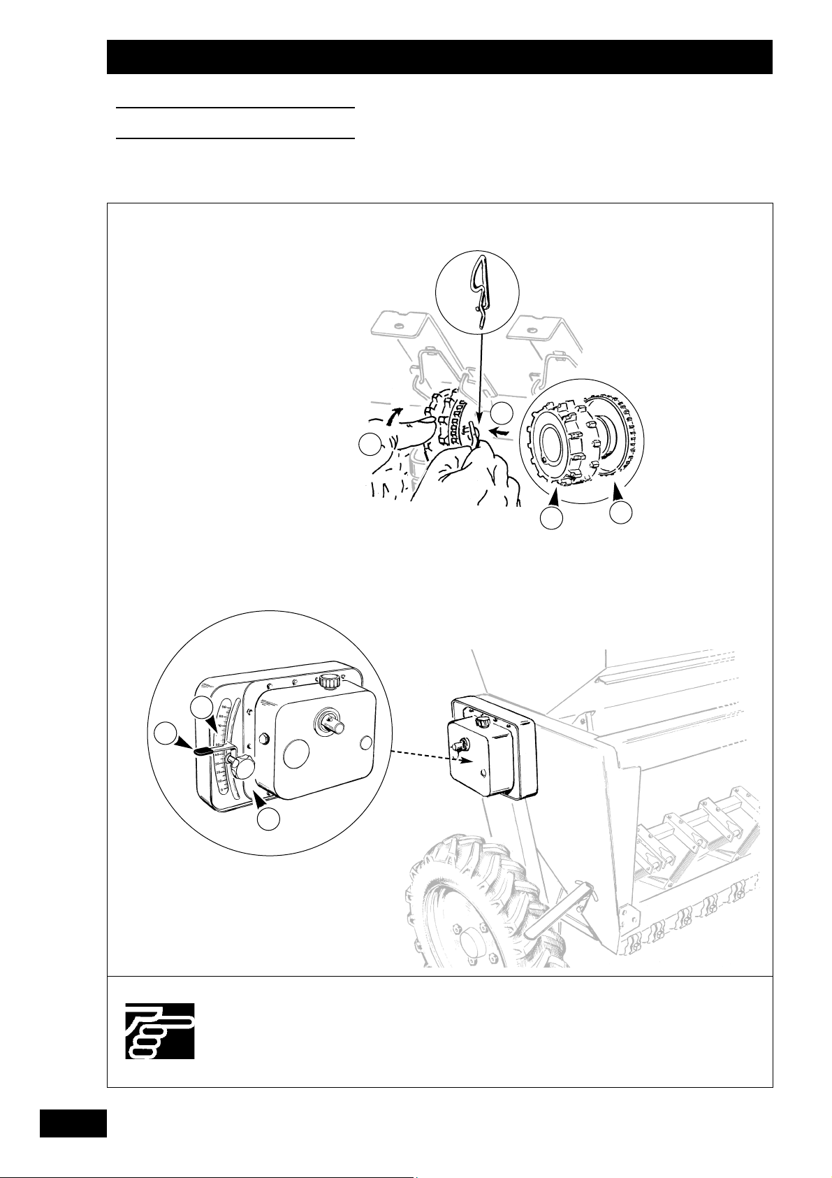
3) Wahl des Nockenrads
Normalrad für Getreide und dicke Körner.
Feines Särad für kleine Körner.
• Den Splint auf dem Schieber des 1. Gehäuses rechts
nehmen.
- Zur Wahl des Särades:
a . Drücken
b . Drehen
4) Getriebe
• Die bei der Abdrehprobe festgelegte Markierung mit der
Rändelschraube
und dem Hebel einstellen.
• Die Ablesung erfolgt über dem flachem Teil
!.
• Jedem Markierungswechsel muß eine Abdrehprobe folgen. Zur Information: 3 Nonius-Gradeinteilungen entsprechen einer Abweichung von ca. 10 kg/ha mit Getreide.
• Markierung von 0 bis 90.
GB
3) Selecting the feeding roller
Standard wheel for cereal and large grain.
Fine wheel for small grain.
• Take hold of the pin on the shutter of the first unit to the
right.
- Take hold of the pin on the shutter of the first unit to
the right.
a . Press
b . Turn
4) Variator
• Using the knob , and lever , set to the mark deter-
mined during the calibration test.
• Read off above the flat part
!.
• Each change to the setting must be followed by a calibration check. For your information, three graduations on
the adjustment scale correspond to a deviation of around
10 kg/ha with cereal.
•Scale from 0 to 90.
3) Sélection de l'ergot
Roue standard pour céréales et grosses graines.
Roue fine pour petites graines.
• Prendre la goupille sur la trappe du 1er boîtier à droite.
- Pour sélectionner la roue de distribution:
a . Appuyer
b . Tourner
4) Variateur
• Mettre le repère déterminé à l’essai de débit à l’aide de la
molette
, et du levier .
• La lecture se fait au dessus de la partie plane !.
• Chaque changement de repère doit être suivie d’un
contrôle de débit. Pour information, 3 graduations de vernier
correspondent à un écart d’environ 10 Kg/ha avec des
céréales.
• Repère de 0 à 90.
Réglages
Settings
Einstellungen
F
D
24
Pour un semis très précis,
il est nécessaire de réaliser
un essai de débit.
Attention à la précision de
votre balance.
A calibration test is necessary for accurate sowing.
Make sure that your scales
are accurate
Für eine sehr präzise Saat
ist eine Abdrehprobe
erforderlich.
Die Waage muß genau
sein.
Réglages
Settings
Einstellungen
2
b
a
1
3
b

25
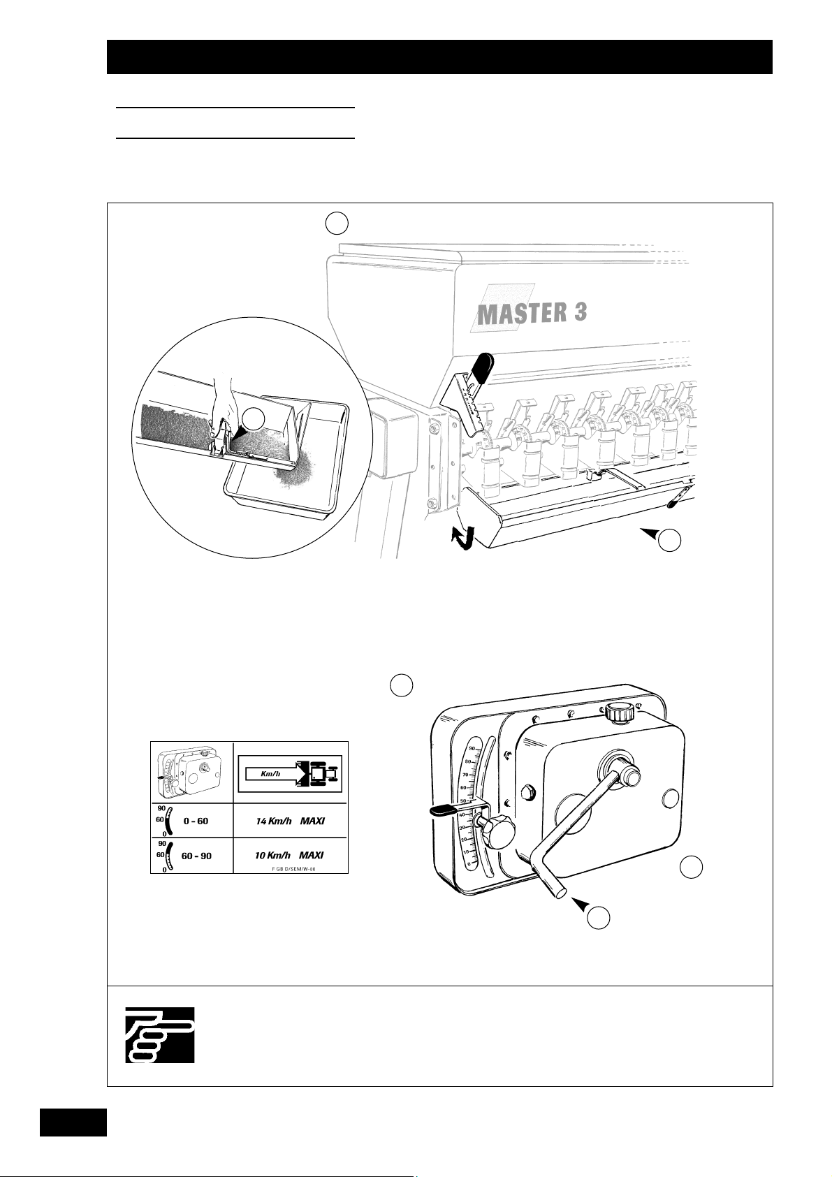
b) Anbringen des Abdrehproben-Sets
• Besorgen Sie sich eine Präzisionswaage und einen Behälter.
• Sich vor Durchführung der Abdrehprobe vergewissern, daß
sich niemand in Nähe der Drillmaschine aufhält.
•Vorgangsweise
a . Die Mulden
öffnen und nach unten drücken,
damit sie unter die Verteilungen kippen.
b . Die Schardruckverstellkurbel
auf die
Getriebewelle stecken.
• Prüfen, ob die benutzten Verteilungen eingeschaltet sind.
• Die Abdrehprobe gemäß den Anweisungen der nächsten
Seiten durchführen.
• Zum einfacheren Entleeren der Mulde den Schieber unter
leichtem Anheben des Hebels
benutzen.
• Die Mulden wieder in Schutzdeckel-Stellung bringen.
GB
b) Setting up the calibration test
• Use accurate scales and a container.
•Before carrying out the test, check that there is no-one
around the seed drill.
• Procedure:
a . Open the tray
and push it downwards so that
it slides beneath the metering device.
b . Fit the depth control crank on to the variator
shaft.
•Check that the metering devices used are engaged.
• Carry out the calibration check in line with the recommendations on the following pages.
• Use the shutter flap to remove the seed from the tray by
lifting the lever
slightly.
• Bring the trough back to the guard position.
b) Mise en place de l’essai de débit
• Procurez-vous une balance précise et un récipient.
•Avant d’effectuer votre essai, vérifier qu’il n’y ait personne
près du semoir.
• Démarche
a . Ouvrir les augets
et les pousser vers le bas
pour les faire basculer sous les distributions.
b . Prendre la manivelle de terrage
et l'engager
sur l'arbre du variateur.
• Vérifier que les distributions utilisées soient enclenchées.
• Effectuer votre essai de débit suivant les recommandations
des pages suivantes
• Pour vider plus facilement la semence de l'auget, utiliser la
trappe en soulevant légèrement le levier
.
•Remettre les augets en position carter
Réglages
Settings
Einstellungen
F
D
26
Réglages
Settings
Einstellungen
1
Mini 5 Kg
Mini 150 Kg
2
3
4
Mini 100 tr
Mini 25 tr
1 tr / s
6 7
8
5
9
10
ha = 0
+
+
5 6 7
m 2,50 3,00 3,50 4,00 4,50 4,80 5,00 6,00 6,66
tr 60 50 43 37,5 33,3 31,25 30 2 5 22 ,5
x 40 = Kg / ha
ou - or - oder
Amorçage
Feeding
Verteilung ankurbeln
B
LÉ
HIVER
M
ASTER
3
12 12,5 13 13,6 14 14,3 15 15,7 16 16,7
40
50
60
70
80
90
100
110
120
130
140
150
160
170
180
190
200
210
220
230
240
250
260
270
280
290
300
19 20 20 21 22 22 23 25 25 26
22 23 24 25 26 26 27 29 29 31
25 26 27 29 29 30 32 33 34 35
28 30 31 32 33 34 35 37 38 39
32 33 34 36 37 38 39 41 42 44
35 36 38 39 40 41 43 45 46 48
38 39 41 43 44 45 47 49 50 52
41 43 44 46 47 48 51 53 54 56
44 46 47 49 51 52 54 56 57 59
47 49 51 53 54 55 57 60 60 63
50 52 54 56 57 58 60 63 64 66
53 55 56 59 60 61 63 66 67 69
55 57 59 61 63 64 66 69 70 72
58 60 62 64 66 67 69 72 72 75
60 62 64 67 68 69 72 74 75 78
63 65 67 69 71 72 74 77 78 80
65 67 69 72 73 74 77 79 81 83
67 70 72 74 76 77 79 82 83
70 72 74 76 78 79 82 85
72 74 76 79 80 81 84
74 76 78 81 83 84
76 78 80 83 85
78 80 83
80 82 85
82 84
VARIÉTÉ: ORVANTIS
TRAITEMENT: AUSTRAL
21
4
1
2
3
3
27
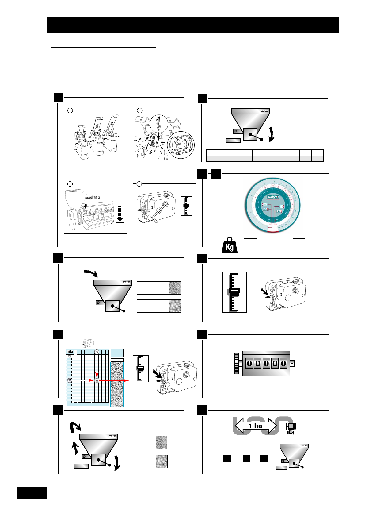
c) Réalisation de l’essai de débit
1) Essai en poste fixe
Procéder au réglage de la distribution comme l’indique
la notice (clapet de fond, trappes etc...).
Mettre la graine dans la trémie
le jour même du
semis (5 Kg en colza / 150 Kg en céréales) et réali-
ser l’essai à suivre.
Régler le variateur suivant le repère indicatif du
tableau (voir chapitre 5).
Amorcer la distribution : 25 tours de manivelle
minimum (l’auget peut être rempli), sauf pour le
colza 100 tours.
Faire l’essai en effectuant le nombre de tours en
fonction de la largeur du semoir.
Nota : tourner régulièrement à 1 tour/seconde.
Peser la quantité recueillie dans les augets avec une balan-
ce précise.
Multiplier par 40 pour obtenir la quantité par ha ou uti-
liser la réglette
(voir page suivante).
Corriger le réglage du variateur (baisser complètement le
levier pour le ramener ensuite à la valeur souhaitée).
Ramener le compteur d’hectares à zéro, après l’essai de
débit.
L’essai en condition réelles est le plus représentatif.
Après un hectare de semis, refaire un essai de véri-
fication (procéder comme ci-dessus à partir de ).
6
6
GB
Réglages
Settings
Einstellungen
F
D
2
2
1
1
3
3
5
5
4
4
7
7
10
10
8
8
9
9
c) Carrying out the calibration test
1) Fixed unit test
Set the distribution as indicated in the manual (baffle
plate, shutters, etc.).
Put the grain in the seed box
on the day of
sowing (5 kg of rape, 150 kg of cereal) and carry
out the following test.
Set the variator to the mark indicated in the table
(see section 5).
Start distribution: a minimum of 25 turns of the
crank (the trough may be filled), or 100 turns for
rape.
Carry out the test by completing the appropriate
number of turns for the width of the seed drill.
N.B. Turn steadily at 1 turn per second.
Weigh the quantity collected in the trays with an accurate
set of scales.
Multiply by 40 to obtain the quantity per hectare or use
the calculator (see next page).
Correct the variator setting (lower the lever completely
then bring it back up to the required value).
Reset the area meter to zero after the calibration test.
The most representative test is one carried out under
real working conditions.
After sowing a hectare, carry out a further check
(proceed as above from step ).
6
6
2
2
1
1
3
3
5
5
4
4
7
7
10
10
8
8
9
9
c) Durchführung der Abdrehprobe
1) Probe im Stillstand
Einstellung der Verteilung gemäß Anweisung vorneh-
men (Bodenklappe, Schieber, usw..).
Das Korn
am Tag der Aussaat in den Saatkasten
geben (5 kg bei Raps/ 150 kg bei Getreide) und die
notwendige Probe durchführen.
Das Getriebe gemäß der in der Tabelle angegebenen
Markierung
einstellen (vgl. Kapitel 5).
Die Verteilung
in Gang bringen: mindestens 25
Kurbelumdrehungen (die Mulde kann gefüllt
werden), aber 100 Umdrehungen für Raps.
Probe vornehmen, indem eine der Drillmaschinenbreite entsprechende Anzahl von Umdrehungen
vorgenommen wird.
Anmerkung: regelmäßig eine
Umdrehung/
Sekunde vornehmen.
In den Mulden aufgefangene Menge mit einer
Präzisionswaage wiegen.
Mit 40 multiplizieren, um die Menge pro ha zu erhalten
oder Einstellscheibe benutzen (s. nächste Seite).
Die Getriebe-Einstellung
korrigieren (den Hebel völlig
senken und dann wieder auf den gewünschten Wert stellen).
Den Hektarzähler nach der Abdrehprobe
wieder auf Null
stellen.
Eine Probe unter reellen Bedingungen ist die beste.
Nach einem Hektar Aussaat eine Probe zur Kontrolle
durchführen (wie o.a. ab Punkt ).
6
6
2
2
1
1
3
3
5
5
4
4
7
7
10
10
8
8
9
9
5
5
5
5
5
5
28
Réglages
Settings
Einstellungen
2
4
3
1

29
2) Probe mit dem Meßstab
• Dieser Meßstab erlaubt Ihnen, die neue Getriebe-
Markierung nach der 1. Abdrehprobe zu bestimmen.
• Die Einstellungen der Verteilung und eine Probe gemäß
den vorausgehenden Seiten vornehmen.
• Benutzung:
- Die Linie der Getriebe-Markierung, die für die
1. Abdrehprobe gedient hat, mit der Linie in
Übereinstimmung bringen, die der bei dieser
Probe in der Mulde aufgefangenen Menge in kg
entspricht.
- Ohne die Scheiben des Meßstabs zu verschieben,
auf der Linie Ihre gewünschte Streumenge auf
der Linie kg/ha markieren.
- Auf der Linie die neue Getriebe-Markierung
ablesen, die Ihrem Saatgut gemäß Ihren
Bedingungen entspricht.
• Nach einem Hektar Aussaat eine neue Probe zur Kontrolle
durchführen.
• Wollen Sie die Streumenge/ha mit dem gleichen Saatgut
auf einer anderen Parzelle ändern, können Sie erneut den
Meßstab verwenden, um die neue Getriebe-Markierung
unter Beibehaltung des gewogenen Wertes der 1.
Abdrehprobe zu ermitteln.
GB
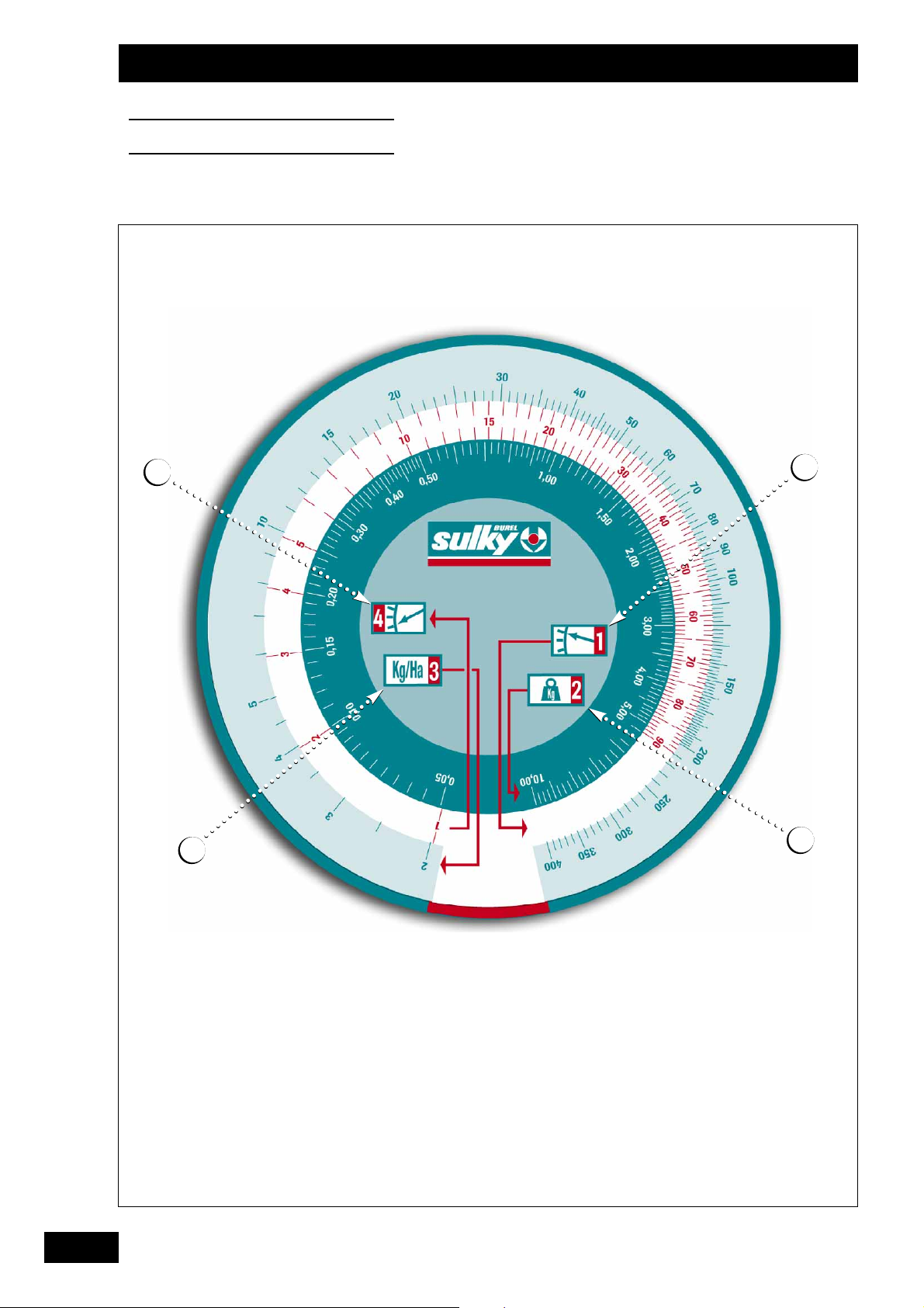
2) Testing with the calculator
• This calculator enables you to determine the new variator
setting after your first calibration test.
• Set the distribution and carry out a test in line with the
recommendations given on the previous pages.
• Use:
- Match line
, the variator setting used for your
first calibration test, up to line which corresponds to the quantity collected in the trough in kg
during this test.
- Without moving the discs on the calculator, iden-
tify your required seeding rate in kg/ha on line .
- On line , read off the new variator setting cor-
responding to your seed and conditions.
• After sowing a hectare, carry out a further check.
• If you wish to change the seeding rate per hectare with
the same seed on another plot, you can use the calculator again to determine the new variator setting by keeping
the weighed quantity obtained in the first calibration test.
2) Essai avec la réglette
• Cette réglette vous permet de déterminer le nouveau
repère de variateur après votre 1er essai de débit.
• Effectuer les réglage de la distribution et un essai suivant
les recommandations données dans les pages précédentes.
• Utilisation :
- Faire coïncider la ligne du repère du variateur
qui a servi à votre 1er essai de débit avec la ligne
qui correspond à la quantité recueillie à cet
essai dans l’auget en Kg.
- Sans bouger les disques de la réglette, repérer sur
la ligne votre débit souhaité sur la ligne Kg/ha.
- Lire sur la ligne le nouveau repère de variateur
correspondant à votre semence suivant vos conditions.
• Après un hectare de semis, refaire un essai de vérification.
• Si vous désirez changer le débit/ha avec la même semence sur une autre parcelle, vous pouvez réutiliser la réglette pour déterminer le nouveau repère du variateur en gardant la valeur de pesée du 1er essai de débit.
Réglages
Settings
Einstellungen
F
D

30
Réglages
Settings
Einstellungen
Utiliser uniquement une
prise simple effet.
Avant la manœuvre des traceurs, vérifier qu'il n'y ait
personne autour de la
machine.
Use a single-acting valve
only.
Before shifting the markers, check that there is
no-one around the
machine.
Ausschließlich ein einfachwirkendes Ventil benutzen.
Sich vor Betätigung der
Spurreißer vergewissern,
daß sich niemand im
Maschinenbereich aufhält.
B
1
2
3

31
Spurreißer
a) In Arbeitsstellung bringen
Die Spurreißer dienen der Markierung am Vorderrad des
Traktors.
• Splint
herausziehen und den Stift freilegen, wobei
der Arm des Spurreiflers mit der anderen Hand festgehal
ten werden muss.
• Den Splint wieder so einsetzen
, dass er den Stift
festklemmt.
• Den Arm absenken und den Lauf des Kabels überprüfen.
• Das Nebenrohr in liegende und vertikale Stellung bringen.
• Nach dem Einsetzen des Rohres (bis zum Anschlag
gegen den Bolzen
), die beiden Schrauben blockieren.
• Zur Einstellung der Scheibe im Verh‰ltnis zur Spur die
Achse auf dem Arm versetzen.
Gleichzeitig können Sie auch die Scheibenneigung einstellen,
um eine mehr oder weniger starke Einstellung am Boden zu
erzielen.
b) Sonderausrüstungen Spurreißer mit hydrauli-
scher Schaltautomatik
• Hydraulikanschluß
- Hydraulikflexschlauch auf dem einfachwirkenden
Schlepperventil mit freiem Rücklauf anschließen.
Ein Drosselventil auf der Hydraulikleitung verhindert das
heftige Heben der Spurreißer.
GB
Markers
a) Setting to working position
The markers put a mark by the front wheel of the tractor.
• Remove the small pin
and pull out the spindle while
holding the marker arm with the other hand.
• Put the pin back into position
to secure the spindle.
•Lower the arm and check cable routing.
• Set the secondary tube in extended and vertical position.
• After setting the tube in position (stopped against the
bolt
), tighten both screws.
•To adjust the disc in relation to the track, slide the shaft
along the arm.
You can adjust the disc angle simultaneously to reduce marking depth.
b) Optional hydraulically-controlled markers with
automatic reverser
• Hydraulic connection
- connect the hydraulic line to the tractor's single-acting
valve with free return.
A flow control system is incorporated into the hydraulic
circuit to avoid sudden lifting of the markers.
Traceurs latéraux
a) Mise en position travail
Les traceurs sont conçus pour un marquage à la roue avant
du tracteur
• Retirer la goupille
et dégager la broche en tenant le
bras de traceur avec l'autre main.
• Remettre la goupille en position
pour bloquer la broche.
• Baisser le bras et vérifier le passage du câble.
• Pour le réglage du disque par rapport à la voie, déplacer
l'axe sur le bras.
Vous pouvez aussi en même temps régler l'inclinaison du
disque pour avoir un réglage au sol plus ou moins important.
b) Options Traceurs à inverseur automatique à com-
mande hydraulique
• Branchement hydraulique
- brancher le flexible hydraulique sur la prise simple effet
du tracteur avec retour libre.
Afin d'éviter la montée brutale des traceurs, un limiteur de
débit est fixé sur le circuit hydraulique.
Réglages
Settings
Einstellungen
F
D
B
B
B

32
Réglages
Settings
Einstellungen
La levée des traceurs ne doit
pas être brutale.
Réaliser les manœuvres en
bout de champ.
Pour des tracteurs équipés de
pneus larges avant, la voie V
peut se prendre à l'intérieur
des pneus.
The markers should be raised
smoothly.
These manoeuvres should be
carried out at the end of the
field.
On tractors equipped with
wide front tyres, the track V
may be measured from the
inside of the tyres.
Spurreißer nie heftig
anheben.
Betätigungen am Feldende
vornehmen.
Bei Schleppern mit breiten
Vorderreifen kann die Spur V
zwischen den Reifeninnenseiten gemessen
werden.
3
1
e
D
V
2

33
Réglages
Settings
Einstellungen
c) Schutzvorrichtung
Die Schutzvorrichtung funktioniert nur bei Spurreißer in
Arbeitstellung.
- Passive Schutzvorrichtung: Sicherheitsbolzen
Typ HM 10 x 90
Klasse 6.8.
Ein Ersatzbolzen ist auf
dem Arm vorgesehen.
d) Funktionsweise
- Belastung « ein Spurreißer hebt sich
- Entlastung « der andere Spurreißer senkt sich
- Belastung « der gesenkte Spurreißer hebt sich
- Entlastung « der andere Spurreißer senkt sich
e) Einstellungen
• EINSTELLUNG DER SPURREIßER ANHAND DER SPUR
e x (n+1) V
D = -
22
DAbstand des Spurreißers bis zum ersten Schar in cm
n Reihenzahl der Drillmaschine
VVorderspur des Schleppers in cm
e Abstand der Schare in cm
D: Maß ab Außensäelement
• Beispiel: Drillmaschine 21 Reihen Abstand 14,3 cm,
Vorderspur des Schleppers 160 cm
<
14,3 x 22160
D = - = 77,3 cm
22
• Einstellung
- mit Hilfe der Kurbel Schraube lockern
- Arm unter gleichzeitiger Einstellung der
Scheibenneigung verlängern.
•
EINSTELLUNG DER SPURREIßER ANHAND DER
SC
HLEPPERMITTE
.
Der Abstand der letzten Saatlinie zum Spurreißerrad ist
gleich _ Arbeitsbreite plus _ Reihenabstand.
f) Anmerkungen
• Regelmäßig die Klemmung der Schraube (4m da N)
überprüfen.
• Den Sicherheitsschrauben-Typ beachten.
GB
c) Safety
The safety device only functions when the marker is in its
working position.
- Passive safety: HM 10X90 class 6.8 safety bolt .
A replacement bolt is provided on the
arm.
d) Operation
- Apply pressure « a marker is raised
- Release pressure « the other marker is lowered
- Apply pressure « the lowered marker is raised
- Release pressure « the other marker is lowered
e) Settings
• TRACK MARKER ADJUSTMENT.
e x (n+1) V
D = -
22
DDistance from the marker to the 1st coulter in cm
n Number of seed drill rows
VTractor front track in cm
e Coulter spacing in cm
D: Measurement to be made from outer coulter unit
• e.g. 21 row drill with 14.3 cm spacing, tractor front track =
160 cm
<
14.3 x 22160
D = - = 77.3 cm
22
•Adjustment
- loosen the screw with the crank
- extend the arm while adjusting the disc at the sam
•
CENTRAL MARKER ADJUSTMENT.
The distance between the last drilling line and the marker
disc is equal to half the working width plus half the gap
between the drilling line and the disc.
f) Notes
• Regularly check the tightening of the screw
(4m da N).
• Use the correct safety screw type.
c) Sécurité
La sécurité ne fonctionne que traceur en position travail.
- Sécurité passive :Boulon de sécurité
type HM 8 x 40 classe 6.8.
Un boulon de remplacement est
prévu sur le bras.
d) Fonctionnement
- Mettre la pression « un traceur se lève
- Relâcher la pression « l'autre traceur se baisse
- Mettre la pression « le traceur baissé se lève
- Relâcher la pression « l'autre traceur se baisse
e) Réglages
• RÉGLAGE DES TRACEURS À LA VOIE.
e x (n+1) V
D = -
22
D Distance du traceur à la 1ère botte en cm
n Nombre de rangs du semoir
V Voie avant du tracteur en cm
e Ecartement des bottes en cm
D : Cote à prendre à partir de l'élément semeur extérieur
• Exemple : semoir 21 rangs écartement 14.3 cm, voie
avant du tracteur 160 cm
14,3 x 22 160
D = - = 77,3 cm
22
• Réglage
- à l'aide de la manivelle, desserer la vis
- allonger le bras en réglant en même temps l'inclinaison
du disque.
• RÉGLAGE DES TRACEURS AU CENTRE.
La distance de la dernière ligne de semis au disque de
traceur est égale à une 1/2 largeur de travail, plus un 1/2
écartement.
f) Remarques
• Vérifier régulièrement le serrage de la vis (4m da N).
•Respecter le type de vis de sécurité.
F
D

34
Réglages
Settings
Einstellungen
Faire attention à bien régler
l'aplomb du semoir.
Bien effectuer l'entretien.
Soigner les réglages de la
herse de recouvrement.
Make sure that the vertical
setting is correctly
adjusted.
Carry out maintenance
thoroughly.
Take care with covering
harrow adjustments.
Auf die gute Senkrechtstellung der Drillmaschine
achten.
Wartung sorgfältig
durchführen.
Besonders auf die Einstellungen der Saategge
achten.
C
a)
b)
1
1
3
2

35
Schardruckeinstellung
a) Schleppschar
• Zentrale Druckverstellung durch Kurbel .
• Unabhängige Einstellung jedes Säelements zum Erhöhen
des Drucks bestimmer Schare, insbesondere hinter den
Schlepperrädern:
- Mindestdruck anlegen
- mit der Hand an der Feder ziehen,
- Spannstift mit der anderen Hand verschieben.
b) Unidisc-Schar
• Das Unidisc-Schar ist für die Arbeit auf Böden mit
Pflanzenresten oder für die vereinfachte
Bodenvorbereitung bestimmt.
•Zentrale Einstellung durch die Kurbeln (wie Schar).
• Einzeleinstellung der Säelemente (wie Schar).
GB
Depth control
a) Suffolk coulter
• Simultaneous handle adjustment .
• Independent unit adjustment to increase the pressure of
certain shares, particularly behind the tractor wheels:
- apply minimum pressure,
- pull the spring with one hand,
- move the pin with the other hand.
b) Unidisc
• The Unidisc has been designed for work on simply prepa-
red soil or in trashy conditions.
• Centralised handle adjustment (cf. Suffolk coulter).
•Independent coulter unit adjustment (cf. Suffolk coulter).
Réglage du terrage
a) Soc trainant
• Réglage centralisé par une manivelle .
• Réglage indépendant par élément pour augmenter la
pression de certains socs, notamment derrière les roues
du tracteur :
- mettre la pression minimum,
- tirer sur le ressort avec votre main,
- déplacer la goupille avec l'autre main.
b) Soc Unidisc
• L'Unidisc a été conçu pour travailler avec des sols
recouvert de résidus ou en préparation de sol simplifié.
• Réglage centralisé par les manivelles (idem soc).
• Réglage indépendant par élément semeur (idem soc).
Réglages
Settings
Einstellungen
F
D
C
C
C

36
Réglages
Settings
Einstellungen
Les réglages de la herse de
recouvrement se font après
avoir réglé sa profondeur
de semis.
The covering harrow is to
be adjusted after setting
the sowing depth.
Saatstriegel erst nach
Einstellung der Sätiefe
einstellen.
D
a)
b
1
2
3
1
2
a
3
b)
2
3
1
b
a

37
Einstellung des Saatstriegels
a) Striegel mit geraden Zinken
• Einstellung der Zinkenneigung :
-3 Stellungen erlauben bei sehr starken Pflanzenresten
einen mehr oder weniger großen Freiraum:
- Den als Anschlag dienenden Stift herausziehen und
Loch wechseln.
•
Druckeinstellung :
Feder drehen
- a - nach unten « mehr Druck
- b - nach oben « weniger Druck
- Neutralstellung in der Mitte.
• Stellung der Zinke in Bezug auf das Schar :
werkseitig eingestellt.
b) Striegel mit Planierzinken
• Einstellung der Zinkenneigung :
-3 Stellungen erlauben die Änderung des Arbeitswinkels
der Zinken:
- Den Stift herausziehen und Loch wechseln.
Die Planierzinke muß unabhängig von den Bedingungen
parallel zum Boden oder leicht "auf der Spitze" über
der Saattiefe arbeiten.
• Druckeinstellung
:
Feder drehen
- a - nach unten « mehr Druck
- b - nach oben « weniger Druck
- Neutralstellung in der Mitte.
GB
Adjusting the covering harrow
a) Straight-tine harrow
• Adjusting the tine angle :
- three positions give different clearances according to
the amount of plant debris
- remove the locking pin and change hole.
•Adjusting the pressure
Turn the spring
- a - downwards « increase the pressure
- b - upwards « reduce the pressure
- Neutral position in the middle.
• Position of tine in relation to the share: factory adjustment.
b) Levelling tine harrow
• Adjusting the tine angle :
-there are three positions for changing the leading angle
of the tines.
- remove the pin and change hole.
Whatever the conditions may be, the levelling tine must
be parallel to the ground or slightly on the tip above the
sowing depth.
•Adjusting the pressure
Turn the spring
- a - downwards « increase the pressure
- b - upwards « reduce the pressure
- Neutral position in the middle.
Réglage de la Herse de recouvrement
a) Herse à dents droites
• Réglage de l'inclinaison des dents :
-3 positions permettent d'avoir un dégagement plus ou
moins important en fonction de la présence de débris
végétaux.
- Retirer la broche servant de butée et changer de
trou.
• Réglage pression
Tourner le ressort
- a - vers le bas « Pression
- b - vers le haut « Soulagement
- Position neutre au milieu
• Position de la dent par rapport au soc : réglage usine.
b) Herse à dents niveleuses
• Réglage de l'inclinaison des dents :
- 3 positions permettent de changer l'angle d'attaque des
dents :
- Retirer la broche et changer de trou.
Quelques soient les conditions, la dent niveleuse doit
travailler parallèle au sol ou légèrement sur la pointe audessus de la profondeur de semis.
• Réglage pression
Tourner le ressort
- a - vers le bas « Pression
- b - vers le haut « Soulagement
- Position neutre au milieu.
Réglages
Settings
Einstellungen
F
D
D
D
D

38
Réglages
Settings
Einstellungen
Vérifier régulièrement la
pression des pneumatiques, celle-ci influe sur la
précision de dosage.
Check tyre pressure
regularly as it affects
metering accuracy.
Reifendruck regelmäßig
kontrollieren, er beeinflußt
die Sämengenpräzision.
a)
1
E
b)
2

39
Einstellung der Spurlockerer
a) Einstellung der Spurlockerer
• Die Radspurlockerer lassen sich einstellen:
- in der Breite gemäß Schlepperspur
- in der Höhe gemäß gewünschter Saattiefe
• Außerdem können die Spurlockerer zum Vermeiden von
Verstopfung durch Umdrehen der Befestigungsklammern
versetzt angeordnet werden.
b) Reifen
• Reifen 125.25
• Der Reifendruck muß auf 1,5 Bar gehalten werden.
• Die Reifen sind umkehrbar, um somit eine Aussenbreite
von 3m zu erreichen.
•Einstellung des Abstreifbleches
- durch Lösen der Schrauben das Abstreifblech so
einstellen, daß nur eine minimale Erdschicht auf den
Reifenprofilen zurückbleibt.
GB
Adjusting the track eradicators
a) Adjusting the track eradicators
• The width of the wheel track eradicators may be adjus-
ted according to the tractor track, and their height according to the required depth control.
• Furthermore, the eradicators may be staggered by reversing the brackets to avoid clogging.
b) Tyres
• Tyre 125.25
•The tyre pressure is to be maintained at 1.5 bar.
•The wheels may be reversed to obtain a width of 3m
overall.
•Adjusting the wheel scraper
- Adjust the wheel scraper by loosening the screws
, so
that a minimum amount of earth sticks to the tyre tread.
Réglage des effaceurs de traces
a) Réglage des effaceurs de traces
• Les effaceurs de traces de roues se réglent :
- en largeur suivant la voie des tracteurs.
- en hauteur suivant l'enterrage désiré.
• En outre, les effaceurs peuvent être disposés en quinconce par retournement des chapes pour éviter le bourrage.
b) Pneumatiques
• Pneumatique 125.25
•La pression de gonflage est à maintenir à 1.5 bar.
•Les roues sont réversibles pour obtenir une largeur hors
tout de 3m.
• Réglage du décrottoir
- en dévissant les vis
, régler le décrottoir de manière à
n'avoir qu'une couche minimum de terre sur les crampons du pneumatique.
Réglages
Settings
Einstellungen
F
D
E
E
E

40
Réglages
Settings
Einstellungen
Pour le bon fonctionne-
ment du jalonnage, assurez-vous que le branchement électrique soit correctement réalisé.
For the tramline system to
function well, make sure
that the electrical connections are correctly made.
Zur guten Funktion der
Fahrgassenschaltung muß
der elektrische Anschluß
korrekt sein.
F
1
2
2
V

41
Fahrgassenanlage
a) Prinzip
• Anlegen von Fahrgassen für spätere Behandlungen mit
Geräten, deren Breite ein Vielfaches der DrillmaschinenArbeitsbreite ist.
b) Funktion
• Fahrgassenmarkierung nach Pflanzenaufgang
- Fernabschaltung von 2 bis 4 Nockenrädern gemäß der
Spur
V des Streu- oder Behandlungsgerätes.
. Handbetätigung
oder elektrische Betätigung
oder Elektronische Steuerung MEDION
• Fahrgasseneinrichtung vor Pflanzenaufgang
(Sonderausrüstung)
- Markierung vor Pflanzenaufgang der für alle Fahrten
festgelegten Spur auf dem Boden.
- Die Montage ist mit elektrischer oder elektronischer
Betätigung möglich.
GB
Tramlining
a) Principle
• Consists of creating tramlines with a view to subsequent
treatment with implements whose width is a multiple of
the working width of the seed drill.
b) Operation
• Post-emergence tramlining
- Two to four metering devices corresponding to the
wheel track
V used for spreading or crop treatment.
. manual control
or electrical control
or MEDION electronic control unit
• Pre-emergence tramlining (optional)
- Tramlines marked in the soil before crop emergence
- Possible mounting with electric or electronic control.
Dispositif de marquage
a) Principe
• Consiste à ménager des passages en vue de traitements
ultérieurs avec des outils de largeur multiple de la largeur
de travail du semoir.
b) Fonctionnement
• Jalonnage post levée
- débrayage à distance de 2 à 4 distributions correspon-
dant à la voie
V de l'outil d'épandage ou de traitement.
. commande manuelle
ou commande électrique
ou commande électronique MEDION
• Jalonnage pré levée (option)
- marquage au sol de la voie déterminée pour tout passa-
ge avant levée de la culture.
- montage possible avec commande électrique ou électronique.
Réglages
Settings
Einstellungen
F
D
F
F
F

42
Réglages
Settings
Einstellungen
3 4
5
1 2 3 4 5 1 2
3
4 5 1
6
6
2 3 4 5 1 2
3
15 m
3 m
18 m
3 m1,5 m
5 5
3 5
6 6
3 6

43
Réglages
Settings
Einstellungen
3 932
12
. 4 2
15 5 3
18
. 6 3
21 7 4
24
. 8 4
m
m
5
3

44
Réglages
Settings
Einstellungen
Maintenir en pression
quelques secondes le
levier du distributeur
hydraulique.
Maintain the pressure on
the hydraulic valve lever for
a few seconds.
Hebel des Hydrauliksteuerventils einige
Sekunden lang drücken.
c)
1
2
3

45
c) Fahrgassenanlage nach Pflanzenaufgang
• Handbetätigung
- Abschaltung durch kabelzug ab Schlepperkabine mit
Hilfe des Hebels
. nach vorn: Abschaltung der Verteilungen
. nach hinten: Saat.
-Hebel
auf jeder Fahrt betätigen, um die Zahl der
Fahrten zu speichern und so die Fahrgassen im richtigen
Moment anzulegen.
- Montage: vgl. Bausatz beiliegende Anweisung.
• Elektrische Betätigung
- Steuert nach Wunsch die abschaltbaren Nockenräder.
Bei Markierung:
. Schalter drücken
1
Nach dem Markieren:
. Schalter drücken 0
GB
c) Post-emergence tramlining
• Manual Control
- The distribution clutch is controlled by a remote line
from the cab with the aid of a lever
. forwards: tramlining
. backwards: sowing.
- After each pass, move the lever
to memorise the
number of passes in order to mark at the right moment.
- Mounting: see instructions with the kit.
• Electrical Control
- Freely controls the clutch-operated distribution.
When marking:
. Press the switch
1
After marking:
. Press the switch
0
c) Jalonnage de post levée
• Commande manuelle
- La commande de débrayage se fait par téléflexible
depuis la cabine à l'aide du levier
. vers l'avant : arrêt des distributions
. vers l'arrière : semis.
- A chaque passage, manoeuvrer le levier
ceci vous
permettra de mémoriser le nombre de passages afin de
jalonner au bon moment.
- Montage : Voir notice jointe avec le kit.
• Commande Electrique
- Commande à volonté les distributions débrayables.
Au moment du marquage :
. Appuyer sur l'interrupteur 1
Après le marquage :
. Appuyer sur l'interrupteur 0
Réglages
Settings
Einstellungen
F
D

46
Réglages
Settings
Einstellungen
Attention de ne pas trop
croiser les tubes de descente.
Make sure that the coulter
tubes are not crossed too
much.
Darauf achten, daß die
Saatrohre nicht zu stark
gekreuzt werden.
®
2
1

47
• Elektronische Betätigung
- Das Automatikprinzip beruht auf der
Spurreißerbetätigung. Das Ausheben der Drillmaschine
in Feldmitte z. B. ändert die festgelegte
Fahrgassenschaltung nicht.
- Vgl. Gerätefunktion auf der MEDION-Anweisung.
• Einstellung der Spur
- Da die Entkupplung der Nockenräder eine feste Stellung
auf dem Saatkasten einnimmt, genügt es, die den
gewählten Säelementen entsprechenden Saatrohre
auszutauschen und sie unter den abgeschalteten
Nockenräder anzubringen.
1 - Die vorrübergehend für die Fahrgasseneinrichtung
abzuschaltenden Säelemente kennzeichnen.
2 - Den oberen Teil ihres Saatrohres aushängen.
3 - Unter den Nockenrädern mit Entkupplungs-Vorrichtung
anbringen.
GB
• Electronic Control
- The principle of automated control is based on the ope-
ration of the markers at the end of the field; raising the
seed drill in the middle of the field, for example, does
not alter the memory.
- Refer to the MEDION instructions to operate the unit.
•Adjusting the track
- As the disengaged metering device is in a fixed position
on the seed box, the tubes
relating to the selected
coulter units just need to be changed and placed beneath the disengaged metering unit.
1 - Identify the coulter units to be shut off intermittently
for the tramlines.
2 - Disconnect the top of the coulter tubes.
3 - Connect them beneath the clutch-operated metering
units.
•Commande Electronique
- Le principe d'automatisme est basé sur la manoeuvre
des traceurs, le fait de lever le semoir en milieu de
champs, par exemple, ne modifie pas le repérage.
- Voir le fonctionnement du boîtier sur la notice MEDION.
• Réglage de la voie
- Le débrayage des distributions ayant une position fixe
sur la trémie, il suffit de changer les tubes de descente
correspondant aux éléments semeurs choisis et de
les placer sous la distribution débrayée.
1 - Repérer les éléments semeurs à condamner par inter-
mittence pour le marquage.
2 - Déboîter le haut de leur tube de descente.
3 - Les emboîter sous les distributions qui sont munies de
l'embrayage.
Réglages
Settings
Einstellungen
F
D

4848
Réglages
Settings
Einstellungen
Faire correspondre la voie
des pré levées avec celle
du post levée.
Match up the pre-emergence and post-emergence
tramlines.
Die Fahrgassenspur vor
Pflanzenaufgang mit der
nach Pflanzenaufgang
abstimmen.
d)
1
1,60 m
1,90 m

49
d) Fahrgassenanlage vor Pflanzenaufgang
• Fahrgassenanlage vor Pflanzenaufgang
(Vorauflaufmarkierer)
- Die Zinken für die Fahrgassenanlage vor Pflanzen-
aufgang
funktionieren gleichzeitig mit der
Fahrgasseneinrichtung nach Pflanzenaufgang.
- Die Fahrgassenspur wird im Werk eingestellt (Angabe
bei Auftrag) und entspricht den abgeschalteten
Nockenrädern.
• Einstellung der Spur
- Zum Ändern der Spur der Vorauflaufmarkierer müssen
die Zinken zur Fahrgassenanlage vor Pflanzenaufgang
auf dem Querträger verschoben werden.
GB
d) Pre-emergence tramlining
• Pre-emergence tramlining (rear marker)
- The rear markers
operate at the same time as the
post-emergence tramlining system.
- The marking track is preset at the factory (specified in
the order) and corresponds to the clutch-operated
metering devices.
•Adjusting the track
- To change the tramlining track, the rear markers need
to be shifted along the crossmember.
d) Jalonnage de pré levée
• Jalonnage de pré levée (marqueur arrière)
- Les dents de pré levée
fonctionnent en simultanée
avec le jalonnage de post levée.
- La voie de marquage est pré-réglée usine (spécification
commande) et correspond aux distributions débrayées.
• Réglage de la voie
- Pour changer la voie des jalonneurs arrière, il est néces-
saire de déplacer les dents de pré levée sur le support transversal.
Réglages
Settings
Einstellungen
F
49
D
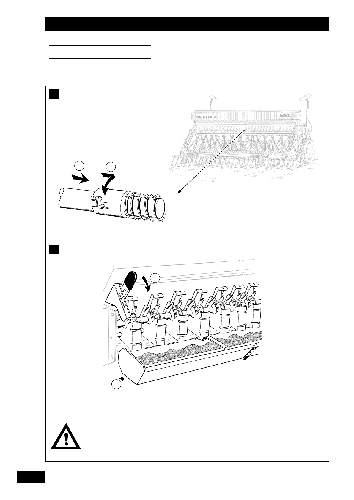
50
Réglages
Settings
Einstellungen
Il est impératif de vider la
trémie après le travail, pour
éviter les dégâts causés
par les rongeurs.
It is essential to empty the
seed box after sowing to
avoid rodent damage.
Saatkasten nach Einsatz
zum Schutz vor Nagetieren
unbedingt völlig entleeren.
1
G
2
H
a
b

51
Abschalten 1/2 Drillmaschine
• Die Zentralhütse zwischen den Halbwellen der Verteilung
kann entkuppelt werden, um der Fahrgassenpassage
zu entsprechen. Nur die linke Seite kann ausgekuppelt
werden.
• Zum Auskuppeln
- a - Schieben
- b - Drehen
Saatkastenentleerung
• Der Saatkasten wird in die Mulde entleert.
• Die Mulde unter die Verteilung stellen und
Bodenklappenhebel
nach unten drücken.
• Bei nur teilweise entleertem Kasten braucht der Hebel
nicht völlig hochgedrückt zu werden, um den Saatfluß zu
stoppen.
GB
Disengaging half of the seed drill
• The centre sleeve between the distribution half-shafts may
be uncoupled to match up with the tramlining. Only the
left-hand side may be disengaged.
•To disengage:
- a - Push
- b - Twist
Emptying the seed box
• The seed box is emptied into the tray .
• Position the tray beneath the metering devices and push
the flap
fully down.
•To stop the grain flow when the seed box is only partly
empty, it is not necessary to raise the lever completely.
Débrayage demi-semoir
• Le désaccouplement de la noix centrale entre les 1/2
arbres de distribution est possible pour correspondre au
passage de jalonnage. Seul le côté gauche est débrayable.
• Pour débrayer
- a - Pousser
- b - Tourner
Vidange de la trémie
• La vidange de la trémie se fait dans l'auget .
• Positionner l'auget sous la distribution et abaisser le levier
de sabots à fond vers le bas.
• Pour stopper l'écoulement de la graine alors que la trémie
n'est que partiellement vide, il n'est pas nécessaire de
lever le levier complètement.
Réglages
Settings
Einstellungen
F
D
G
G
G
H
H
H
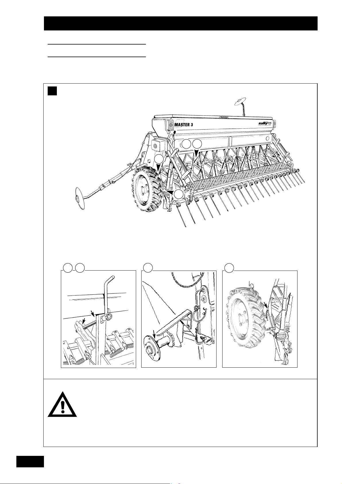
52
Bien respecter les périodici-
tés de vidange du variateur.
Ne jamais graisser les distributions et les tubes de descente.
Vérifier le serrage des
écrous principaux après
10 heures d'utilisation.
Change the variator oil
according to the recommended frequency.
Never grease the metering
devices or the coulter tubes.
Check the tightness of the
main nuts after ten hours of
use.
Die Ölwechselabstände für
das Ölbadgetriebe einhalten.
Niemals die Nockenräder
und Saatrohre schmieren.
Nach 10 Betriebsstunden
prüfen, ob sich die Hauptmuttern nicht gelockert
haben.
Entretien
Maintenance
Wartung
B
4
1
2
4
1
3
3
2

53
Wartung
• Saatkasten innen sauberblasen.
• Drillmaschine ohne Hochdruck waschen
• Zur Vermeidung von Verletzungen beim
Reinigen und bei der Instandhaltung Schutzbrille
und Handschuhe tragen.
• Sind Saatgutrückstande vorhanden, eine Staubschutzmaske tragen.
Schmierung
• Maschine regelmäßig am Anfang und Ende der Aussaat
Kampagne schmieren.
Nuß der Schardruckstange (1)
Nuß der Schardruckverstellkurbel (1)
Radnabe (2)
Gelenke der äußeren Säelemente (2 oder 4).
•Kennzeichnung-Auskupplungsfedern ölen (am besten
Gleitschutzmittel aufsprühen).
• Antriebskette ölen.
• Zahnräder des Hektarzählers schmieren (etwas Fett)
• Ölstand des Getriebes kontrollieren (Drillmaschine waagerecht), bis zum roten Punkt mit Öl für automatische
Getriebe (ATF -DEXTRON II D) ergänzen.
Ölwechsel alle 500 ha oder alle 2 Jahre, wenn diese
Fläche nicht erreicht wird.
Prüfung
• Das Spiel der Säelementstangen ist durch Anziehen der
auf Kegeln montierten Gelenkbolzen einstellbar.
•Die Schare aus Gußeisen auswechseln, bevor der
Verschleiß die Seiten der Stahlblechkolter erreicht und
dadurch die Aussaatqualität beeinträchtigt.
GB
Maintenance
• Clean inside the seed box with a blower.
•Wash the seed drill without using high pressure.
• For cleaning and maintenance, wear protective
glasses and gloves to prevent injury.
• If there is left-over seed, wear a dust mask to
prevent inhaling dust.
Lubrication
• Grease the machine regularly at the beginning and end of
the season.
Depth control connecting rod coupling (1)
Depth control crank coupling (1)
Wheel hubs (2)
Outside rows (2 or 4).
•Lubricate the tramlining clutch springs (preferably by
spraying on an antiseize compound).
•Lubricate the drive chain.
• Grease the areameter pinion (knob of grease).
• Check the oil level in the variator (with drill horizontal) and
top up to the red dot with ATF - DEXTRON II D automatic
gearbox oil.
Change the oil every 500 hectares, or every 2 years at the
most.
Checks
• The coulter unit rod set may be adjusted by tightening the
cone-mounted hinge pin.
• Change the cast iron shares before wear reaches the
sides of the sheet metal coulter otherwise the grain
sowing quality will be affected.
Entretien
• Souffler intérieur trémie
•Laver le semoir sans haute pression
• Pour le nettoyage et entretien, porter lunette
de protection et gants pour éviter toutes
blessures.
• Si il reste de la semence porter un masque
anti-poussière pour éviter toute inhalation.
Graissage
• Procéder régulièrement à un graissage de la machine en
début et fin de campagne.
Noix de bielle de terrage (1)
Noix de manivelle de terrage (1)
Moyeux de roue (2)
Rangs extérieurs (2 ou 4).
• Huiler les ressorts de débrayage pour repérage, (il est préférable de pulvériser du dégrippant).
• Huiler la chaîne de distribution.
•Graisser les pignons de compteur d'ha (une noix de graisse).
• Vérifier le niveau d'huile du variateur (semoir horizontal),
ajuster le niveau au point rouge avec de l'huile de boîte de
vitesses automatiques. ATF - DEXTRON II D
Effectuer la vidange tous les 500 ha ou tous les 2 ans si la
surface n'est pas effectuée.
Vérification
• Le jeu de tiges d'éléments semeurs est réglable par serra-
ge de l'axe d'articulation monté sur cônes.
• Changer les socs en fonte avant que l'usure atteigne les
flancs latéraux de la botte en tôle.
Dans le cas contraire, vous perturbez la qualité d'enterrage de la graine.
F
A
A
A
3
D
Entretien
Maintenance
Wartung
B
C
C
C
B
B

54
D
Entretien
Maintenance
Wartung
6 mm
1
2
4
3

55
GB
Distribution
• Ne jamais laisser de la semence dans la trémie pendant
une longue période.
• Ouvrir les trappes
et les clapets de fond pendant
la période de remisage.
• Ne jamais graisser les distributions et les tubes de descente.
Contrôle
Un réglage défectueux des clapets de fond peut provo-
quer un surdosage en cours de semis.
Il est conseillé de contrôler et de régler si nécessaire après
chaque période de semis.
-Positionner le levier des clapets de fond au repère 1.
- Vérifier visuellement dans un premier temps la distance
entre le clapet et la roue à ergots.
- Si nécessaire, mettre une cale
de 6mm entre le clapet
et la roue à ergots" grosses graines" (entre les ergots, sur
une partie lisse).
- Ajuster la distance à l'aide de la vis .
F
D
D
D
D
Entretien
Maintenance
Wartung
Verteilung
• Das Saatgut nie für länger im Saatkasten lassen.
• Die Schieber
und die Bodenklappen bei längeren
Abstellzeiten öffnen.
• Nie die Verteilungen oder die Saatrohre schmieren.
Kontrolle
Eine mangelhafte Einstellung der Bodenklappen kann wäh-
rend der Aussaat zu einer Überdosierung führen.
Es ist ratsam, nach jeder Saatperiode Kontrollen und ggf. notwendige Neueinstellungen vorzunehmen.
- Den Hebel der Bodenklappen auf die Markierung 1 einstellen.
- Den Abstand zwischen Bodenklappe und dem Nockenrad
erst einmal mit bloßem Auge überprüfen.
-Wenn nötig, einen 6 mm-Keil
zwischen Klappe und das
Nockenrad für "große Körner" (zwischen die Nocken, an
eine glatte Stelle) schieben.
- Den Abstand mit der Schraube
nachregeln.
Distribution
• Never leave seed in the hopper for any length of time.
• Open the shutters
and flaps during storage.
• Never lubricate the metering devices and chutes.
Checks
Incorrect flap setting can induce oversowing.
It is recommended to check settings and adjust if necessary
after each sowing campaign.
- Set the flap lever on index 1.
-Visually check first the distance between the flap and the
studded wheel.
- If necessary, insert a 6-mm spacer
between the “coarse
grain” studded wheel studs (insert studs on a smooth section).
-Adjust the distance with the screw
.

56
Entretien
Maintenance
Wartung
E

57
Technische Daten
a) Identifizierung
• Bei Abnahme Ihrer Maschine folgende Informationen vermerken: MASCHINENNUMMER / MASCHINENTYP / ZUBEHÖRTEILE
b) Technische Daten
GB
Technical specifications
a) Identification
• Note the following information on receipt of your machine: MACHINE NUMBER / MACHINE TYPE / ACCESSORIES
b) Specifications
F
E
E
D
Entretien
Maintenance
Wartung
Master 3 300
Width (m) 3
Number of rows 19/21/25
Spacing (cm) 15,7/14,2/12
Transport width (m) 3,00
Seed box capacity ( l ) 440
Filling Height (m) 0,95
Weight of drill fully equipped
with Sulffolk coulter (kg)
450
Minimum recommended power (hp) 65 - 100
Master 3 300
Breite (m) 3
Reihenzahl 19/21/25
Abstand (cm) 15,7/14,2/12
Transportbreite (m) 3,00
Saatkasteninhalt ( l ) 440
Füllhöhe (m) 0,95
Gewicht mit Schleppschar völlig
ausgerüstete Drillmachine (kg)
450
Empfohlene Mindestleistung (PS)
65 - 100
Caractéristiques techniques
a) Identification
• Lors de la prise en charge de votre machine, notez en page 2 les informations suivantes : NUMERO DE LA MACHINE / TYPE DE MACHINE / ACCESSOIRES
b) Caractéristiques
E
Master 3 300
Largeur (m) 3
Nombre de rangs 19/21/25
Ecartement (cm) 15,7/14,2/12
Largeur transport (m) 3,00
Contenance trémie ( l ) 440
Hauteur de remplissage (m) 0,95
Poids avec soc trainant semoir équipé (kg) 450
Puissance minimum recommandée (ch)
65 - 100

58
Entretien
Maintenance
Wartung
F
Interdiction de monter sur la passerelle de charge-
ment pendant le travail.
Platform is for loading purposes only.
Aufenthalt auf dem Ladesteg während der Fahrt
nicht gestattet.
Danger d'écrasement
Danger of squeezing
Quetschgefahr

59
GB
F
D
Entretien
Maintenance
Wartung
Positions Autocollants
Des étiquettes adhésives relatives à la sécurité ont
été placées sur votre machine.
Leur but est de contribuer à votre sécurité et à celle d'autrui.
Lisez leur contenu et contrôlez leur emplacement.
Revoyez les étiquettes ainsi que les instructions contenues
dans la notice d'instructions avec l'opérateur de la machine.
Gardez les étiquettes propres et lisibles. Remplacez-les
lorsqu'elles sont détériorées.
F
F
Sticker positions
Warning notices relating to safety are affixed to your
machine.
Their aim is to contribute to your safety and to the safety of
others.
Know their contents and check their location.
Review the safety notices as well as the instructions
contained in this operating manual.
If any safety notices become illegible or lost they should be
replaced.
Sicherheitsaufkleber
Sicherheitsaufkleber sind auf Ihrer Maschine angebracht.
Sie sollen zu Ihrer Sicherheit und der anderer Personen
beitragen. Sie sorgfältig lesen und ihre Anbringung
kontrollieren. Aufkleber und Bedienungsanweisung mit dem
Benutzer der Maschine durchgehen. Aufkleber sauber und
lesbar halten. Beschädigte Aufkleber auswechseln.
F

60
Chaque équipement cor-
respond à des conditions
particulières à adapter au
sol et au semis.
Every accessory relates to
special conditions which
need to be adapted to the
soil and the seed.
Jede Ausrüstung entspricht
besonderen Bedingungen
und ist dem Boden und der
Saat anzupassen.
Equipements
Accessories
Ausrüstungen
A
B
2
4
1
3
1
2

61
Sätiefenbegrenzer
(Tiefenkontrolle in "lockerem" Boden)
•Montage des Begrenzers
- Die beiden Muttern
H10 des Schars abnehmen
- Den Begrenzer montieren
- Höhe des Begrenzers in Bezug auf die Scharspitze am
Boden einstellen und anziehen.
• Ausführung, Einstellung
- Zur Ermittlung des Einstellwertes des Begrenzers kann
ein Paßstück
benutzt werden, dessen Höhe der
gewünschten Saattiefe entspricht.
Bei schwierigen Bodenbedingungen sollten jedoch einige
Zentimeter mehr vorgesehen werden.
• Mit dieser Ausrüstung sollte ein höherer Schardruck an
den Säelementen benutzt werden.
Uniband-Schar (Bandsaat 6-8 cm)
•Die Montage erfolgt auf der Rückseite des Schars ohne
Spezialwerkzeug
- Schare vor Montage reinigen
- Uniband anbringen
- Haltefeder anbringen
GB
Depth limiter (depth control in loose soil)
• Fitting the limiter
- Remove the two H10 nuts
from the share
- Fit the limiter
- Adjust the height of the limiter in relation to the point of
the share to the ground and tighten.
•Adjustment
- To determine the limiter setting, a block
whose height
corresponds to the required sowing depth may be used.
In difficult soil conditions, however, you are advised to add
on a few centimetres.
•With this equipment, it is also recommended to increase
the depth control pressure on the coulter units.
Uniband share (sowing a 6-8 cm wide band)
• Mounted at the rear of the share without the need for
special tools.
- Clean the share before mounting
- Fit the uniband
- Fit the spring pin
Limiteur de profondeur
(contrôle de la profondeur en sol "souple")
• Montage du limiteur
- Retirer les deux écrous
H10 du soc
- Monter le limiteur
- Régler la hauteur du limiteur par rapport à la pointe du
soc au sol et serrer.
• Réalisation, réglage
- Pour déterminer la cote de réglage du limiteur, vous
pouvez vous aider d'une cale
dont sa hauteur corres-
pond à la profondeur de semis désiré.
Toutefois, si les conditions de sol sont difficiles, il est
conseillé de mettre quelques centimètres en plus.
•Avec cet équipement, il est aussi conseillé de mettre plus
de pression de terrage aux éléments semeurs.
Soc Uniband ( semis étale 6-8 cm)
•Le montage se fait à l'arrière du soc sans clés spéciales
- Nettoyer les socs avant le montage
- Mettre l'uniband
- Mettre la broche élastique
F
A
A
A
D
B
B
B
4
Equipements
Accessories
Ausrüstungen

62
Suivre les instructions de
montage.
Attention : pression
hydraulique !
Comply with assembly
instructions.
Caution: hydraulic pressure!
Montageanweisungen
einhalten.
Vorsicht: Hydraulikdruck!
Equipements
Accessories
Ausrüstungen
C
a)
1
-
1
+

63
Streumengen-Modulation MS
Siehe beiliegende Anleitung.
GB
MS flow rate modulation
See instructions attached.
Modulation de débit MS
voir notice jointe.
F
D
Equipements
Accessories
Ausrüstungen
C
C
C
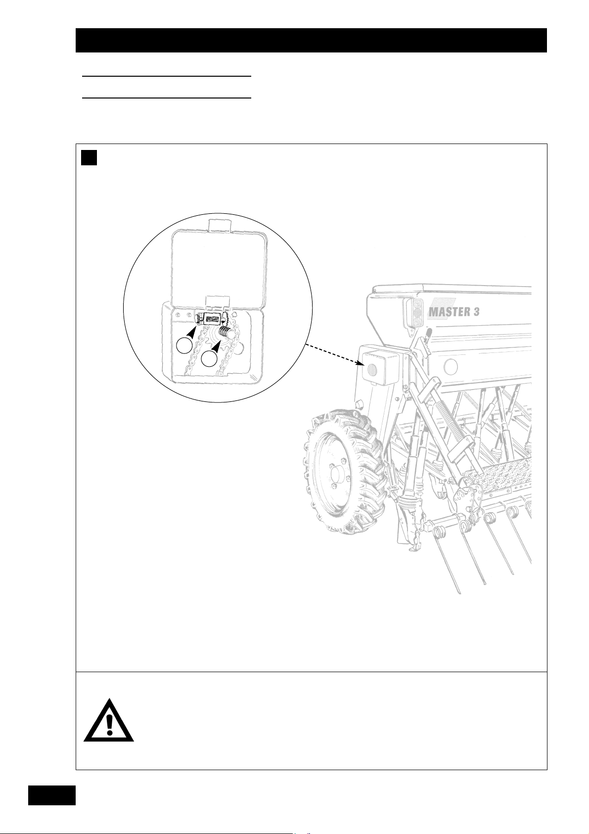
64
Après avoir mis le comp-
teur à zéro, tourner la
molette en sens inverse
jusqu'à l'encliquetage.
After resetting the meter to
zero, turn the knob the
other way until a click is
heard.
Nach Nullstellung des
Zählers das Rädchen bis
zum Einrasten in entgegengesetzte Richtung drehen.
Equipements
Accessories
Ausrüstungen
D
1
2

65
Hektarzähler
• Funktion
- Auf der linken Seite der Drillmaschine angeordnet.
- Direktablesung der Fläche für die Arbeitsbreiten.
Schwarze Zahlen
« ha
Rote Zahlen
« Ar
• Montage
- Den Hektarzähler in dem Gehäuse auf der linken
Seite des Masters so anbringen, daß die Zähne des
Kettenrades zwischen den Windungen der Feder
liegen.
Kettenrad für Master 300
« 20 Zähne
- Die beiden Muttern anziehen, ohne die Scheiben zu
vergessen.
GB
Areameter
• Operation
- Located on the left-hand side of the seed drill.
- The surface area can be read directly for working widths.
Black figures
« hectares
Red figures
« ares
• Assembly
- Place the areameter in the casing on the left-hand
side of the MASTER, so that the cog teeth lock into the
spring spires .
20-tooth cog on MASTER 300
- Tighten the two nuts, not forgetting to insert the
washers.
Compteur d'hectares
• Fonctionnement
- Situé sur le côté gauche du semoir.
- La lecture de la surface est directe pour les largeurs de
travail.
Chiffres noirs
« Hectares
Chiffres rouges
« Ares
• Montage
- Placer le compteur d'hectares dans le carter situé sur
le côté gauche du MASTER, de façon que les dents du
pignon soient intercalées entre les spires du ressort
.
Pignon pour MASTER 300
« 20 dents
- Serrer les deux écrous, sans oublier les rondelles.
F
D
Equipements
Accessories
Ausrüstungen
D
D
D

66
Tableaux de réglage
Setting charts
Einstelltabellen
21
Rappel pré-réglages
Trappes (3 positions)
Ergots (2 positions)
Clapet de fond (6 positions)
Variateur (Repères 0 à 90)
Pre-setting reminder
Shutters (3 positions)
Feeding rollers (2 positions)
Baffle plate (6 positions)
Variator (Scale from 0 to 90)
Zur Erinnerung: Voreinstellungen
Schieber (3 Stellungen)
Nockenräder (2 Stellungen)
Bodenklappe (6 Stellungen)
Ölbadgetriebe (Markierungen 0 bis 90)
F
GB
D
A
4
1
2
3
3

• Blé • Wheat • Weizen . . . . . . . . . . . . . . 68-69
• Orge • Barley • Gerste . . . . . . . . . . . . . . . 70-71
• Colza • Rape • Raps . . . . . . . . . . . . . . . . 72-73
• Lin • Linseed • Leinsaat . . . . . . . . . . . . . 74
• Triticale • Triticale • Triticale . . . . . . . . . . . . . . 75
• Lupin • Lupin • Lupine . . . . . . . . . . . . . . 76
• Pois • Peas • Erbsen . . . . . . . . . . . . . . 77
• Féverole • Field beans • Ackerbohnen . . . . . . . . 78-79
• Trèfle • Clover • Klee . . . . . . . . . . . . . . . 80
• Maïs • Maize • Mais . . . . . . . . . . . . . . . . 81
• Fétuque • Fescue • Schwingel . . . . . . . . . . . 82-83
• Lotier • Bird's-foot • Flügelginsterweide
cornicule trefoil . . . . . . . . . . . . . . . . . . . 84
• Radis • Radish • Radieschen . . . . . . . . . 85
• Phacélia • Phacelia • Phazelia . . . . . . . . . . . . 86
• Navette • Rape • Rübsen . . . . . . . . . . . . 87
• Ray grass • Rye-grass • Ray-Gras . . . . . . . . . . . 88-89
• Moutarde • White • Weißer
blanche mustard Senf . . . . . . . . . . . . . 90-91
• Oeillette • Oil poppy • Schlafmohn . . . . . . . . . 92
• Vesce • Vetch • Wicke . . . . . . . . . . . . . . 93
• Avoine • Oat • Hafer . . . . . . . . . . . . . . . . 94
• Luzerne • Lucern • Luzerne . . . . . . . . . . . . 95
67
5
B
LÉ
HIVER
M
ASTER
3
12 12,5 13 13,6 14 14,3 15 15,7 16 16,7
40
50
60
70
80
90
100
110
120
130
140
150
160
170
180
190
200
210
220
230
240
250
260
270
280
290
300
19 20 20 21 22 22 23 25 25 26
22 23 24 25 26 26 27 29 29 31
25 26 27 29 29 30 32 33 34 35
28 30 31 32 33 34 35 37 38 39
32 33 34 36 37 38 39 41 42 44
35 36 38 39 40 41 43 45 46 48
38 39 41 43 44 45 47 49 50 52
41 43 44 46 47 48 51 53 54 56
44 46 47 49 51 52 54 56 57 59
47 49 51 53 54 55 57 60 60 63
50 52 54 56 57 58 60 63 64 66
53 55 56 59 60 61 63 66 67 69
55 57 59 61 63 64 66 69 70 72
58 60 62 64 66 67 69 72 72 75
60 62 64 67 68 69 72 74 75 78
63 65 67 69 71 72 74 77 78 80
65 67 69 72 73 74 77 79 81 83
67 70 72 74 76 77 79 82 83
70 72 74 76 78 79 82 85
72 74 76 79 80 81 84
74 76 78 81 83 84
76 78 80 83 85
78 80 83
80 82 85
82 84
V
ARIÉTÉ
: O
RVANTIS
T
RAITEMENT
: A
USTRAL
Tableaux de réglage
Setting charts
Einstelltabellen
F
B
GB
D
3
4
Tableaux de débit
Les réglages des tableaux ne sont
donnés qu'à titre indicatif.
Vérifier votre débit hectare, pour
plus de précision (voir chapitre 2).
Seeding rate charts
The chart settings are provided as
an indication only. Check your
seeding rate per hectare for grea
ter accuracy (see section 2).
Sämengentabellen
Die Einstellungen in den Tabellen
dienen nur als Hinweis. Die von
Ihnen gewählte Sämenge zwecks
größerer Präzision kontrollieren
(vgl. Kapitel 2)
25
23
21
19
33
31
29
27
12
13
14,2
15,7
12,1
12,9
13,7
14,8

68
B
LÉ
HIVER
M
ASTER
3
12 12,5 13 13,6 14 14,3 15 15,7 16 16,7
40
50
60
70
80
90
100
110
120
130
140
150
160
170
180
190
200
210
220
230
240
250
260
270
280
290
300
RÉF:
0
2
2
19 20 20 21 22 22 23 25 25 26
22 23 24 25 26 26 27 29 29 31
25 26 27 29 29 30 32 33 34 35
28 30 31 32 33 34 35 37 38 39
32 33 34 36 37 38 39 41 42 44
35 36 38 39 40 41 43 45 46 48
38 39 41 43 44 45 47 49 50 52
41 43 44 46 47 48 51 53 54 56
44 46 47 49 51 52 54 56 57 59
47 49 51 53 54 55 57 60 60 63
50 52 54 56 57 58 60 63 64 66
53 55 56 59 60 61 63 66 67 69
55 57 59 61 63 64 66 69 70 72
58 60 62 64 66 67 69 72 72 75
60 62 64 67 68 69 72 74 75 78
63 65 67 69 71 72 74 77 78 80
65 67 69 72 73 74 77 79 81 83
67 70 72 74 76 77 79 82 83
70 72 74 76 78 79 82 85
72 74 76 79 80 81 84
74 76 78 81 83 84
76 78 80 83 85
78 80 83
80 82 85
82 84
1
1
1
2
3
V
ARIÉTÉ
: O
RVANTIS
T
RAITEMENT
: A
USTRAL
Tableaux de réglage
Setting charts
Einstelltabellen

69
B
LÉ
HIVER
M
ASTER
3
12 12,5 13 13,6 14 14,3 15 15,7 16 16,7
40
50
60
70
80
90
100
110
120
130
140
150
160
170
180
190
200
210
220
230
240
250
260
270
280
290
300
RÉF:
0
2
2
21 22 23 24 25 25 27 28 28 30
25 26 27 28 29 30 31 33 33 35
28 30 31 32 33 34 36 38 38 40
32 34 35 37 38 39 41 42 43 45
36 37 39 41 42 43 45 47 48 50
40 41 43 45 46 47 49 51 52 54
43 45 47 49 50 51 53 55 56 58
47 49 50 52 54 55 57 59 60 62
50 52 54 56 57 58 61 63 64 66
53 55 57 59 61 62 64 66 67 70
56 58 60 63 64 65 67 70 71 73
59 61 63 66 67 68 70 73 74 76
62 64 66 68 70 71 73 76 77 80
65 67 69 71 73 74 76 79 80 83
67 69 71 74 75 77 79 82 84
70 72 74 77 78 79 82
72 74 77 79 81 82
75 77 79 82 84
77 79 82 85
79 82 85
82 85
84
1
1
1
2
3
V
ARIÉTÉ
: O
RVANTIS
T
RAITEMENT
: J
OCK FLEX I
T2
Tableaux de réglage
Setting charts
Einstelltabellen

70
Tableaux de réglage
Setting charts
Einstelltabellen
O
RGE
HIVER
M
ASTER
3
12 12,5 13 13,6 14 14,3 15 15,7 16 16,7
40
50
60
70
80
90
100
110
120
130
140
150
160
170
180
190
200
210
220
230
240
250
260
270
280
290
300
RÉF:
0
2
2
28 29 30 31 32 33 34 36 36 38
32 33 34 35 36 37 39 41 41 43
35 36 38 40 41 42 43 45 46 48
39 40 42 44 45 46 48 50 51 53
43 44 46 48 49 50 52 55 55 58
46 48 50 52 53 54 57 59 60 62
50 52 54 56 57 58 60 63 64 66
53 55 57 59 61 62 64 67 68 70
57 59 60 63 64 65 68 70 71 73
60 62 64 66 68 69 71 74 75 77
63 65 67 69 71 72 74 77 78 80
66 68 70 72 74 75 77 80 81
68 71 73 75 77 78 81
71 73 75 78 80 81
74 76 78 81
76 79 81
79 81
81
1
1
1
2
3
V
ARIÉTÉ
: O
ROSTAR
T
RAITEMENT
: G
AUCHO

71
Tableaux de réglage
Setting charts
Einstelltabellen
O
RGE
HIVER
M
ASTER
3
12 12,5 13 13,6 14 14,3 15 15,7 16 16,7
40
50
60
70
80
90
100
110
120
130
140
150
160
170
180
190
200
210
220
230
240
250
260
270
280
290
300
RÉF:
0
2
19 20 21 22 23 23 24 25 26 27
23 24 25 26 26 27 28 30 30 32
26 27 28 30 30 31 33 34 35 37
29 31 32 33 34 35 37 39 40 41
33 34 36 37 38 39 41 43 44 46
36 38 39 41 42 43 45 47 48 50
40 41 43 45 46 47 49 52 52 55
43 45 46 49 50 51 53 55 56 59
46 48 50 52 53 54 57 59 60 62
49 51 53 55 57 58 60 63 64 66
52 54 56 59 60 61 64 66 67 70
55 57 59 62 63 64 67 69 70 73
58 60 62 65 66 68 70 73 74 76
61 63 65 68 69 70 73 76 77 79
64 66 68 70 72 73 76 79 80 83
66 69 71 73 75 76 79 82 83
69 71 73 76 78 79 82 85
71 74 76 78 80 82 85
74 76 78 81 83 84
76 78 81 84
78 81 83
81 83
83
1
1
1
2
3
2
V
ARIÉTÉ
: V
ANESSA
T
RAITEMENT
: G
AUCHO
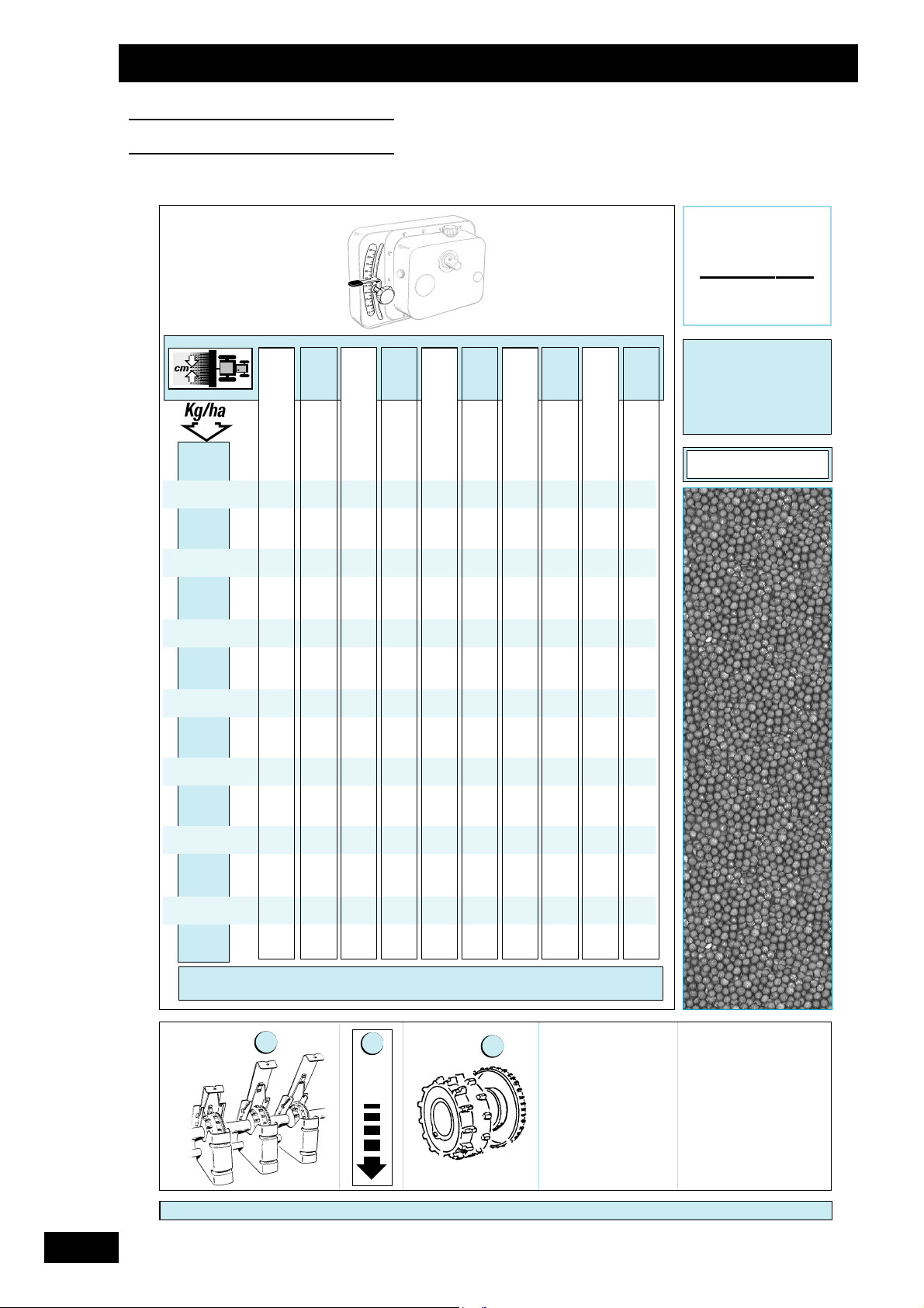
72
Tableaux de réglage
Setting charts
Einstelltabellen
RÉF:
0
2
1
2
3
1
1
2
C
OLZA
D
’
HIVER
M
ASTE
R
3
12 12,5 13 13,6 14 14,3 15 15,7 16 16,7
1,5
2
2,5
3
3,5
4
4,5
5
5,5
6
6,5
7
7, 5
8
8,5
6677778888
88899991010 10
991010 10 11 11 12 12 13
10 11 11 12 12 13 13 14 14 15
12 13 13 14 14 14 15 16 16 17
14 14 15 16 16 16 17 18 19 19
15 16 17 17 18 18 19 20 21 22
17 18 18 19 20 20 22 23 23 24
19 19 20 21 22 23 24 25 25 27
20 21 22 23 24 25 26 27 28 29
22 23 24 25 26 27 28 29 30 31
24 25 26 27 28 29 30 32 32 34
25 27 28 29 30 31 32 34 35 36
V
ARIÉTÉ
: F
RÉDÉRIC
T
RAITEMENT
: T
HIRAM

73
Tableaux de réglage
Setting charts
Einstelltabellen
C
OLZA
D
’
HIVER
M
ASTE
R
3
12 12,5 13 13,6 14 14,3 15 15,7 16 16,7
1,5
2
2,5
3
3,5
4
4,5
5
5,5
6
6,5
7
7, 5
8
8,5
RÉF:
0
7 778888999
89910101010111112
10 10 11 11 12 12 13 13 13 14
12 12 13 13 14 14 15 15 16 16
13 14 15 15 16 16 17 18 18 19
15 16 16 17 18 18 19 20 20 21
17 18 18 19 20 20 21 22 22 23
19 19 20 21 22 22 23 24 25 26
20 21 22 23 24 24 25 26 27 28
22 23 24 25 25 26 27 28 29 30
24 24 25 27 27 28 29 30 31 32
25 26 27 28 29 30 31 32 33 34
27 28 29 30 31 32 33 34 35 36
1
2
3
2
1
1
2
V
ARIÉTÉ
: P
OLEN
T
RAITEMENT
: T
HIRAM

74
Tableaux de réglage
Setting charts
Einstelltabellen
L
IN
OLÉAGINEUX
M
AS
TER
3
12 12,5 13 13,6 14 14,3 15 15,7 16 16,7
40
50
60
70
80
90
100
110
120
130
140
150
160
170
180
190
RÉF:
0
2
2
20 21 22 23 23 24 25 26 27 28
24 25 26 27 28 29 30 32 32 34
28 29 30 32 33 33 35 37 37 39
32 33 35 36 37 38 40 42 42 44
36 38 39 41 42 43 45 47 47 49
40 42 43 45 46 47 49 51 52 54
44 45 47 49 50 51 54 56 57 59
47 49 51 53 55 56 58 60 61 64
51 53 55 57 59 60 62 65 66 68
55 57 59 61 62 63 66 69 70 72
58 60 62 64 66 67 70 72 74
61 63 66 68 70 71 74
64 67 69 71 73 74
68 70 72 75
1
1
1
2
3
V
ARIÉTÉ
: M
IKAEL
T
RAITEMENT
: P
ROCHLORAZE

75
Tableaux de réglage
Setting charts
Einstelltabellen
T
RITICALE
M
ASTER
3
12 12,5 13 13,6 14 14,3 15 15,7 16 16,7
40
50
60
70
80
90
100
110
120
130
140
150
160
170
180
190
200
210
220
230
240
250
260
RÉF:
0
2
2
17 18 19 19 20 21 22 23 23 24
21 22 23 24 24 25 26 28 28 29
24 26 27 28 29 29 31 32 33 34
28 29 31 32 33 34 35 37 37 39
32 33 34 36 37 38 39 41 42 44
35 37 38 40 41 42 44 46 46 48
39 40 42 44 45 46 48 50 51 53
42 44 45 47 49 50 52 54 55 57
45 47 49 51 52 53 56 58 59 61
49 50 52 55 56 57 60 62 63 66
52 54 56 58 60 61 63 66 67 70
55 57 59 62 63 64 67 70 71 73
58 60 62 65 67 68 71 73 74 77
61 63 66 68 70 71 74 77 78 80
64 67 69 71 73 74 77 80 81 83
67 69 72 74 76 77 80 83 84
70 72 75 77 79 80 83
73 75 77 80 82 83
75 78 80 82 84
78 80 82 85
80 82 84
1
1
1
2
3
V
ARIÉTÉ
: C
ARNAC
T
RAITEMENT
: T2

76
Tableaux de réglage
Setting charts
Einstelltabellen
L
UPIN
M
ASTER
3
12 12,5 13 13,6 14 14,3 15 15,7 16 16,7
40
50
60
70
80
90
100
110
120
130
140
150
160
170
180
190
200
210
220
230
240
250
260
270
280
290
300
RÉF:
0
2
2
15 16 17 17 18 18 19 20 21 22
18 18 19 20 21 21 22 23 24 25
20 21 22 23 24 24 25 27 27 29
22 23 24 26 27 27 29 30 31 32
25 26 27 29 30 30 32 34 34 36
27 29 30 32 33 33 35 37 38 40
30 31 33 35 36 36 38 40 41 43
33 34 36 37 39 40 42 44 45 47
35 37 38 40 42 43 45 47 48 50
38 40 41 43 45 46 48 50 51 53
40 42 44 46 47 48 51 53 54 56
43 45 47 49 50 51 53 56 57 59
45 47 49 51 53 54 56 58 59 61
48 50 52 54 55 56 59 61 62 64
50 52 54 56 58 59 61 63 64 66
52 54 56 59 60 61 63 66 66 69
55 57 58 61 62 63 65 68 69 71
57 59 61 63 64 65 68 70 71 73
59 61 63 65 66 67 70 72 73 75
61 63 64 67 68 69 72 74 75 77
62 64 66 69 70 71 73 76 77 80
64 66 68 70 72 73 75 78 79 82
66 68 70 72 74 75 78 80 82
68 70 72 74 75 77 80 83 84
1
1
3
2
1
V
ARIÉTÉ
: A
MIGA
T
RAITEMENT
: -

77
Tableaux de réglage
Setting charts
Einstelltabellen
P
OIS
FOURRAGER
M
ASTER
3
12 12,5 13 13,6 14 14,3 15 15,7 16 16,7
120
130
140
150
160
170
180
190
200
210
220
230
240
250
260
270
280
290
300
310
320
330
340
350
360
380
400
RÉF:
0
2
2
15 15 16 17 17 18 19 20 20 21
16 17 17 18 19 19 20 21 22 23
17 18 19 20 20 21 22 23 24 25
19 19 20 21 22 23 24 25 26 27
20 21 22 23 24 24 26 27 28 29
21 22 23 25 25 26 28 29 30 31
23 24 25 26 27 28 29 31 32 33
24 25 27 28 29 30 31 33 34 35
26 27 28 30 31 31 33 35 36 37
27 28 30 31 32 33 35 37 38 39
29 30 31 33 34 35 37 39 40 41
30 32 33 35 36 37 39 41 41 43
32 33 35 36 38 38 40 43 43 45
33 35 36 38 39 40 42 44 45 47
35 36 38 40 41 42 44 46 47 49
36 38 39 41 43 44 46 48 49 51
38 39 41 43 44 45 48 50 51 53
39 41 43 45 46 47 49 51 52 55
40 42 44 46 48 49 51 53 54 56
42 44 46 48 49 50 53 55 56 58
43 45 47 49 51 52 54 56 57 60
45 47 49 51 52 53 56 58 59 61
46 48 50 52 54 55 57 60 61 63
48 50 51 54 55 56 59 61 62 64
49 51 53 55 57 58 60 62 63 66
52 54 56 58 59 60 63 65 66 69
54 56 58 61 62 63 66 68 69 71
1
1
5
1
2
3
V
ARIÉTÉ
: A
SSAS
T
RAITEMENT
: N
ON TRAITÉ

78
Tableaux de réglage
Setting charts
Einstelltabellen
FÉVEROLE
M
AS
TER
3
12 12,5 13 13,6 14 14,3 15 15,7 16 16,7
120
130
140
150
160
170
180
190
200
210
220
230
240
250
260
270
280
290
300
310
320
330
340
350
360
380
400
RÉF:
0
2
2
16 17 18 19 20 20 21 23 23 25
18 19 20 21 21 22 23 25 26 27
19 20 21 23 23 24 26 27 28 29
21 22 23 25 26 26 28 29 30 32
23 24 25 27 28 28 30 32 32 34
24 26 27 29 30 30 32 34 35 37
26 27 29 31 32 32 34 36 37 39
28 29 31 32 34 34 36 38 39 41
30 31 33 34 36 37 39 41 42 44
31 33 34 36 38 39 41 43 44 46
33 35 36 38 40 41 43 45 46 48
35 36 38 40 42 43 45 47 48 50
36 38 40 42 43 44 47 49 50 52
38 40 42 44 45 46 49 51 52 54
40 42 44 46 47 48 51 53 54 56
42 43 45 48 49 50 53 55 56 58
43 45 47 49 51 52 54 57 58 60
45 47 49 51 53 54 56 59 60 62
46 48 50 53 54 55 58 60 62 64
48 50 52 54 56 57 60 62 63 66
50 52 54 56 58 59 61 64 65 67
51 53 55 58 59 60 63 66 67 69
53 55 57 59 61 62 65 67 68 71
54 56 58 61 62 64 66 69 70 73
57 59 61 64 65 67 69 72 73
60 62 64 67 68 70 72
1
1
1
2
3
6
V
ARIÉTÉ
: I
RENA
T
RAITEMENT
: Q
UINOLATE PRO FL

79
Tableaux de réglage
Setting charts
Einstelltabellen
FÉVEROLE
M
AS
TER
3
12 12,5 13 13,6 14 14,3 15 15,7 16 16,7
120
130
140
150
160
170
180
190
200
210
220
230
240
250
260
270
280
290
300
310
320
330
340
350
360
380
400
RÉF:
0
2
2
17 18 19 20 21 22 23 24 25 26
19 20 21 23 23 24 25 27 28 29
21 22 23 25 26 26 28 29 30 32
23 24 25 27 28 29 30 32 33 34
25 26 28 29 30 31 33 34 35 37
27 28 30 31 32 33 35 37 38 40
29 30 32 33 35 35 37 39 40 42
31 32 34 36 37 38 40 42 43 45
33 34 36 38 39 40 42 44 45 47
35 36 38 40 41 42 45 47 48 50
36 38 40 42 43 44 47 49 50 53
38 40 42 44 46 47 49 52 53 55
40 42 44 46 48 49 52 54 55 58
42 44 46 48 50 51 54 57 58 60
44 46 48 51 52 53 56 59 60 63
46 48 50 53 54 56 58 61 62 65
48 50 52 55 56 58 61 64 65 68
50 52 54 57 59 60 63 66 67 70
52 54 56 59 61 62 65 68 69 72
53 56 58 61 63 64 67 70 72 75
55 58 60 63 65 66 69 72 74 77
57 60 62 65 67 68 71 75 76 79
59 61 64 67 69 70 73 77 78 81
61 63 66 69 71 72 75 79 80 83
62 65 68 71 73 74 77 81 82 85
66 69 71 74 76 78 81 84
69 72 75 78 80 81 85
1
1
1
2
3
6
V
ARIÉTÉ
: C
ASTEL
T
RAITEMENT
: Q
UINOLATE PRO

80
Tableaux de réglage
Setting charts
Einstelltabellen
T
RÈFLE
VIOLET
M
ASTER
3
12 12,5 13 13,6 14 14,3 15 15,7 16 16,7
V
ARIÉTÉ
: S
ALINO
T
RAITEMENT
:
10
11
12
14
16
18
20
22
24
26
28
30
32
34
36
38
40
42
RÉF:
0
2
5
556
5667
556778
55667889
55667789910
66778891010 11
7788991011 11 12
88991010 11 12 12 13
991010 11 11 12 13 13 14
10 10 11 11 12 12 13 14 14 15
11 11 12 12 13 13 14 15 15 16
12 12 13 13 14 14 15 16 16 17
13 13 14 14 15 15 16 17 17 18
14 14 15 15 16 16 17 18 18 19
15 15 16 16 17 17 18 19 19 20
1
2
1
2
3
1
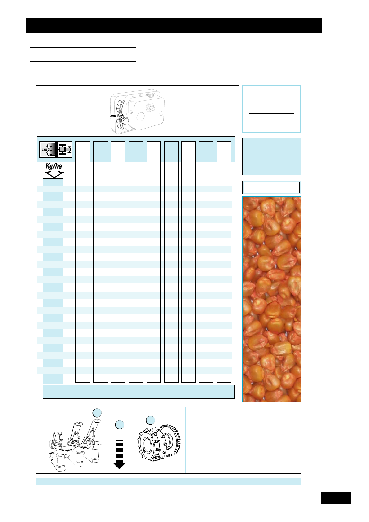
81
Tableaux de réglage
Setting charts
Einstelltabellen
M
AÏS
M
ASTER
3
25 33 37,5 50
V
ARIÉTÉ
: F
UXXOL
T
RAITEMENT
:
5
6
7
8
9
10
11
12
14
16
18
20
22
24
26
28
30
32
34
36
38
40
42
44
46
48
50
RÉF:
0
2
2
5
6
7
58
569
6710
57811
68913
7101116
8111318
9121521
10 14 16 23
11 16 18 25
12 17 20 28
13 18 22 30
15 20 24 32
16 22 25 34
17 23 27 36
18 25 29 38
19 27 30 40
21 28 32 41
22 30 34 43
23 31 35 44
24 32 37 46
25 34 38 47
26 35 39 49
1
1
2
1
3

82
Tableaux de réglage
Setting charts
Einstelltabellen
F
ÉTUQUE
ÉLEVÉE
M
ASTE
R
3
12 12,5 13 13,6 14 14,3 15 15,7 16 16,7
5
6
7
8
9
10
11
12
14
16
18
20
22
24
26
28
30
32
34
36
38
40
42
44
46
48
50
RÉF:
0
2
8 999101011111112
910101011111212 1213
10 11 11 12 12 12 13 13 14 14
12 12 13 14 14 14 15 16 16 17
14 14 15 16 16 17 18 18 19 20
16 16 17 18 18 19 20 21 21 22
18 18 19 20 21 21 22 23 24 25
19 20 21 22 23 24 25 26 27 28
21 22 23 24 25 26 27 29 29 31
23 24 25 27 28 28 30 31 32 33
25 26 28 29 30 31 32 34 34 36
27 28 30 31 32 33 35 36 37 39
29 31 32 33 34 35 37 39 40 42
31 33 34 36 37 38 40 41 42 44
33 35 36 38 39 40 42 44 45 47
35 37 38 40 41 42 44 46 47 49
37 39 40 42 44 44 47 49 50 52
39 41 42 44 46 47 49 51 52 54
41 43 44 47 48 49 51 54 54 57
1
2
1
2
3
1
V
ARIÉTÉ
: D
ULCIA
T
RAITEMENT
: -

83
Tableaux de réglage
Setting charts
Einstelltabellen
F
ÉTUQUE
ÉLEVÉE
M
ASTE
R
3
12 12,5 13 13,6 14 14,3 15 15,7 16 16,7
5
6
7
8
9
10
11
12
14
16
18
20
22
24
26
28
30
32
34
36
38
40
42
44
46
48
50
RÉF:
0
2
9 10 10 10 11 11 12 12 12 13
10 11 11 12 12 12 13 13 14 14
11 12 12 13 13 13 14 15 15 15
12 13 13 14 14 15 15 16 16 17
14 15 15 16 16 17 18 18 19 20
16 17 17 18 19 19 20 21 21 22
18 19 20 20 21 21 22 23 24 25
20 21 22 23 23 24 25 26 26 27
22 23 24 25 25 26 27 28 29 30
24 25 26 27 28 28 30 31 32 33
26 27 28 29 30 31 32 34 34 36
28 29 30 31 32 33 34 36 37 38
30 31 32 33 34 35 37 39 39 41
32 33 34 36 37 38 39 41 42 44
33 35 36 38 39 40 42 44 45 47
35 37 38 40 41 42 45 47 48 50
37 39 41 43 44 45 47 49 50 52
39 41 43 45 46 47 50 52 53 55
41 43 45 47 49 50 52 55 56 58
43 45 47 49 51 52 55 57 58 61
1
2
1
2
3
1
V
ARIÉTÉ
: M
YLÉNA
T
RAITEMENT
: -

84
Tableaux de réglage
Setting charts
Einstelltabellen
L
OT I E R
CORNICULE
M
AS
TER
3
12 12,5 13 13,6 14 14,3 15 15,7 16 16,7
5
6
7
8
9
10
11
12
14
16
18
20
22
24
26
28
30
32
34
36
38
40
42
44
46
48
50
RÉF:
0
26272829303132343436
31 32 33 35 36 37 39 40 41 43
36 37 39 41 42 43 45 47 48 50
41 43 44 46 48 49 51 53 54 56
46 48 50 52 53 54 57 59 60 62
51 53 55 57 59 60 62 65 66 68
56 58 60 62 64 65 67 70 71 73
60 62 64 67 68 69 72 74
68 70 73 75
2
2
1
2
3
1
1
V
ARIÉTÉ
: L
ÉO
T
RAITEMENT
: -

85
Tableaux de réglage
Setting charts
Einstelltabellen
R
ADIS
M
AS
TER
3
12 12,5 13 13,6 14 14,3 15 15,7 16 16,7
9
10
11
12
14
16
18
20
22
24
26
28
30
32
34
36
38
40
RÉF:
0
2
5 5555
555588866
5666677777
6777788889
78889991010 10
89910101011111112
10 10 10 11 11 11 12 12 13 13
11 11 11 12 12 12 13 14 14 14
12 12 12 13 13 14 14 15 15 16
13 13 14 14 15 15 16 16 17 17
14 14 15 15 16 16 17 18 18 19
15 15 16 16 17 17 18 19 19 20
16 16 17 18 18 19 20 20 21 22
17 17 18 19 19 20 21 22 22 23
18 18 19 20 21 21 22 23 24 25
19 20 20 21 22 22 24 25 25 27
20 21 21 23 23 24 25 26 27 28
1
1
2
3
2
1
V
ARIÉTÉ
: A
DIOS
T
RAITEMENT
: -

86
Tableaux de réglage
Setting charts
Einstelltabellen
P
HACÉLIA
M
ASTER
3
12 12,5 13 13,6 14 14,3 15 15,7 16 16,7
10
11
12
14
16
18
20
22
24
26
28
30
32
34
36
38
40
42
44
46
48
50
RÉF:
0
5 556
5556667
56667778
567778889
56788899910
6789991010 10 11
78910101011121212
891011 11 11 12 13 13 13
9101112121213141415
10 11 12 13 13 13 14 15 15 16
11 12 13 14 14 15 15 16 16 17
12 13 14 15 15 16 16 18 18 18
13 14 15 16 16 17 18 19 19 20
14 15 16 17 17 18 19 20 20 21
15 16 17 18 19 19 20 21 21 22
16 17 18 19 20 20 21 23 23 24
17 18 19 20 21 21 22 24 24 25
18 19 20 21 22 22 24 25 25 26
19 20 21 22 23 23 25 26 26 28
20 21 22 23 24 25 26 28 28 29
21 22 23 24 25 26 27 29 29 30
22 23 24 26 26 27 28 30 30 32
2
1
2
3
2
1
V
ARIÉTÉ
: A
MÉRIGO
T
RAITEMENT
:
1
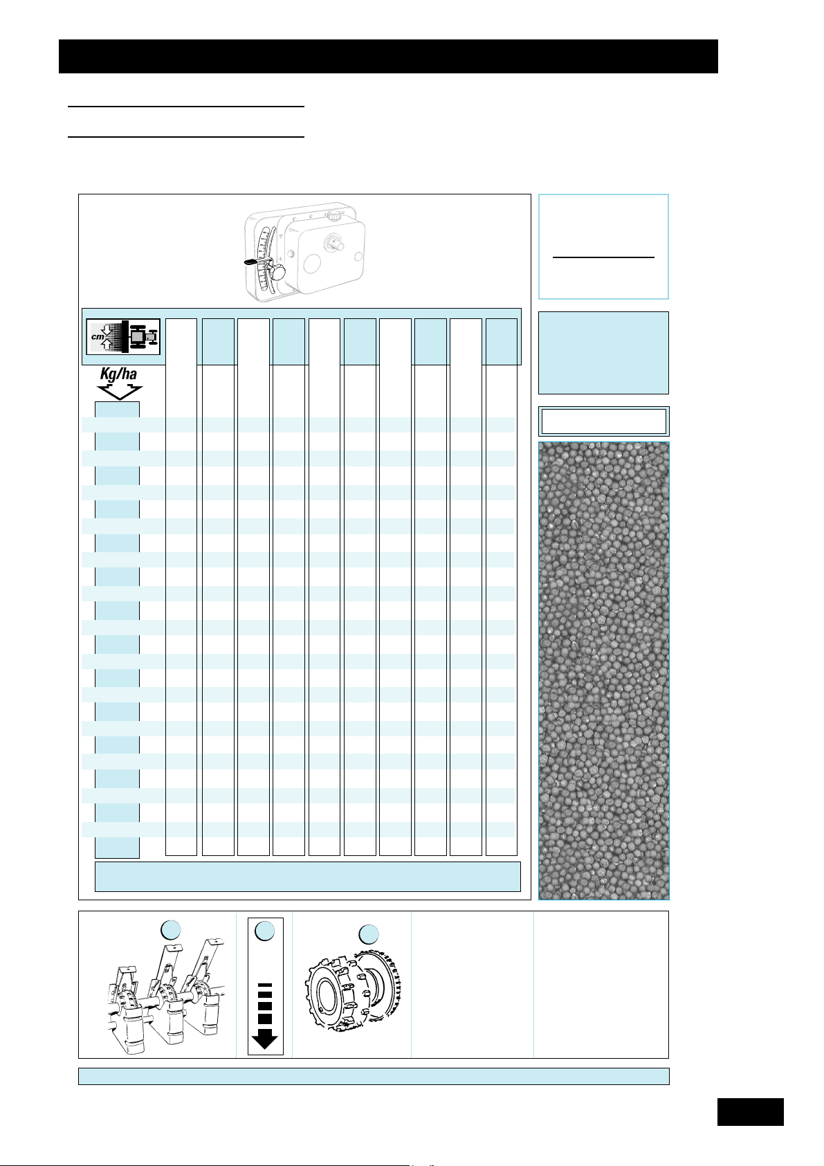
87
Tableaux de réglage
Setting charts
Einstelltabellen
N
AVETTE
M
ASTER
3
12 12,5 13 13,6 14 14,3 15 15,7 16 16,7
5
6
7
8
9
10
11
12
14
16
18
20
22
24
26
28
30
32
34
36
38
40
42
44
46
48
50
RÉF:
0
17181819202021222223
20 21 22 23 24 24 25 26 27 28
24 24 25 27 27 28 29 31 31 33
27 28 29 30 31 32 34 35 36 37
30 31 33 34 35 36 38 40 40 42
34 35 36 38 39 40 42 44 45 47
37 39 40 42 43 44 47 49 50 52
40 42 44 46 47 48 51 53 54 56
47 49 51 54 55 56 59 61 62 64
54 56 58 61 62 63
60 62 64
1
2
3
2
2
1
1
V
ARIÉTÉ
: J
UPITER
T
RAITEMENT
: -

88
Tableaux de réglage
Setting charts
Einstelltabellen
R
AY G RA S S
M
ASTER
3
12 12,5 13 13,6 14 14,3 15 15,7 16 16,7
5
6
7
8
9
10
11
12
14
16
18
20
22
24
26
28
30
32
34
36
38
40
42
44
46
48
50
RÉF:
0
2
9 991010 10 11 11 12 12
10 10 10 11 11 11 12 13 13 13
11 11 11 12 12 13 13 14 14 15
12 12 13 13 14 14 14 15 15 16
14 14 15 15 16 16 17 18 18 19
15 16 17 18 18 18 19 20 21 22
17 18 19 20 20 21 22 23 23 24
19 20 21 22 23 23 24 25 26 27
21 22 23 24 25 25 27 28 28 30
23 24 25 26 27 28 29 30 31 32
25 26 27 29 29 30 32 33 34 35
27 28 29 31 32 32 34 35 36 38
29 30 32 33 34 35 36 38 39 40
31 32 34 35 36 37 39 40 41 43
33 34 36 37 38 39 41 43 44 46
35 36 38 39 41 41 43 45 46 48
37 38 40 42 43 44 46 48 49 51
39 40 42 44 45 46 48 50 51 53
41 42 44 46 47 48 50 53 54 56
42 44 46 48 49 50 53 55 56 58
1
2
1
2
3
1
V
ARIÉTÉ
: B
OXER
T
RAITEMENT
: -

89
Tableaux de réglage
Setting charts
Einstelltabellen
R
AY G RA S S
D
’
ITALIE
M
ASTER
3
12 12,5 13 13,6 14 14,3 15 15,7 16 16,7
5
6
7
8
9
10
11
12
14
16
18
20
22
24
26
28
30
32
34
36
38
40
42
44
46
48
50
RÉF:
0
2
7 77
777888
77 7888999
78889991010 10
89991010 10 11 11 12
9101010111111121213
11 11 11 12 12 13 13 14 14 15
12 13 13 14 14 15 15 16 16 17
14 14 15 16 16 17 17 18 19 19
15 16 17 18 18 18 19 20 21 22
17 18 18 19 20 20 21 22 23 24
19 19 20 21 22 22 23 25 25 26
20 21 22 23 24 24 25 27 27 28
22 23 24 25 26 26 27 29 29 30
23 24 25 27 27 28 29 31 31 33
25 26 27 28 29 30 31 33 33 35
27 28 29 30 31 32 33 35 35 37
28 29 31 32 33 33 35 37 37 39
30 31 32 34 35 35 37 39 39 41
31 33 34 35 36 37 39 40 41 43
33 34 35 37 38 39 41 42 43 45
34 36 37 39 40 41 42 44 45 47
1
2
1
2
3
1
V
ARIÉTÉ
: D
ANERGO
T
RAITEMENT
: -

90
Tableaux de réglage
Setting charts
Einstelltabellen
M
OUTARDE
BLANCHE
M
ASTER
3
12 12,5 13 13,6 14 14,3 15 15,7 16 16,7
5
6
7
8
9
10
11
12
14
16
18
20
22
24
26
28
30
32
34
36
38
40
42
44
46
48
50
RÉF:
0
15 15 16 17 17 17 18 19 20 20
18 18 19 20 21 21 22 23 24 25
21 22 22 24 24 25 26 27 28 29
24 25 26 27 28 29 30 32 32 34
27 28 29 31 32 32 34 36 37 38
30 31 33 34 36 36 38 40 41 43
33 35 36 38 39 40 42 45 46 48
37 38 40 42 43 44 47 49 50 52
43 45 47 49 51 52 55 57 58 61
50 52 54 57 58 60 62 65 66 68
56 59 61 63 65 66 69 71 72 74
62 65 67 69 71 72 74
68 70 72 73 74
72 74 75
75
2
2
1
2
3
1
1
V
ARIÉTÉ
: C
APRI
T
RAITEMENT
: -

91
Tableaux de réglage
Setting charts
Einstelltabellen
M
OUTARDE
BLANCHE
M
ASTER
3
12 12,5 13 13,6 14 14,3 15 15,7 16 16,7
5
6
7
8
9
10
11
12
14
16
18
20
22
24
26
28
30
32
34
36
38
40
42
44
46
48
50
RÉF:
0
16 17 18 19 19 20 21 21 22 23
20 21 21 22 23 23 24 26 26 27
23 24 25 26 27 27 28 30 30 31
26 27 28 29 30 31 32 34 34 36
29 30 31 33 34 34 36 38 38 40
32 33 35 36 37 38 40 41 42 44
35 37 38 40 41 42 43 45 46 48
38 40 41 43 44 45 47 49 50 52
44 46 48 50 51 52 54 56 57 60
50 52 54 56 57 58 61 63 64 67
55 58 60 62 64 65 67 70 71 74
61 63 65 68 69 71 73
66 68 71 73
71 73
2
2
1
2
3
1
1
V
ARIÉTÉ
: A
STA
T
RAITEMENT
: -

92
Tableaux de réglage
Setting charts
Einstelltabellen
O
EILLETTE
M
ASTER
3
12 12,5 13 13,6 14 14,3 15 15,7 16 16,7
1
1,5
2
2,5
3
3,5
4
4,5
5
5,5
6
6,5
RÉF:
0
5 5 55556666
7778888999
991010 10 10 11 11 12 12
11 11 12 12 13 13 14 14 14 15
13 14 14 15 15 15 16 17 17 18
15 16 16 17 18 18 19 20 20 21
17 18 19 20 20 21 22 23 23 24
19 20 21 22 23 23 24 25 26 27
22 22 23 24 25 26 27 28 29 30
24 25 26 27 28 28 30 31 32 33
26 27 28 29 30 31 32 34 35 36
2
2
1
2
3
1
1
V
ARIÉTÉ
: -
T
RAITEMENT
: -

93
Tableaux de réglage
Setting charts
Einstelltabellen
V
ESCE
COMMUNE
M
ASTER
3
12 12,5 13 13,6 14 14,3 15 15,7 16 16,7
V
ARIÉTÉ
: O
PALE
T
RAITEMENT
:
20
22
24
26
28
30
32
34
36
38
40
42
44
46
48
50
RÉF:
0
2
2
5
556
5667
556 7 78
55667889
55667789910
6677889101011
7788991011 11 12
88991010 11 12 12 13
991010 11 11 12 13 13 14
10 10 11 11 12 12 13 14 14 15
11 11 12 12 13 13 14 15 15 16
12 12 13 13 14 14 15 16 16 17
1
1
2
1
3

A
VOINE
HIVER
M
ASTE
R
3
12 12,5 13 13,6 14 14,3 15 15,7 16 16,7
40
50
60
70
80
90
100
110
120
130
140
150
160
170
180
190
200
210
220
230
240
250
260
270
280
290
300
RÉF:
0
2
2
25 26 27 29 30 30 32 33 34 35
30 32 33 35 36 36 38 40 41 43
36 37 39 40 42 43 45 47 48 50
41 43 44 46 48 49 51 53 54 56
46 48 50 52 53 54 57 59 60 63
51 53 55 57 59 60 62 65 66 68
56 58 60 62 64 65 68 70 71 74
60 62 65 67 69 70 73 75 76 79
65 67 69 72 73 75 77 80 81 83
69 71 73 76 77 79 81 84 84
73 75 77 80 81 82 85
76 79 81 83 84
80 82 84
83 85
1
1
1
2
3
V
ARIÉTÉ
: E
VORA
T
RAITEMENT
: G
AUCHO
Tableaux de réglage
Setting charts
Einstelltabellen
94
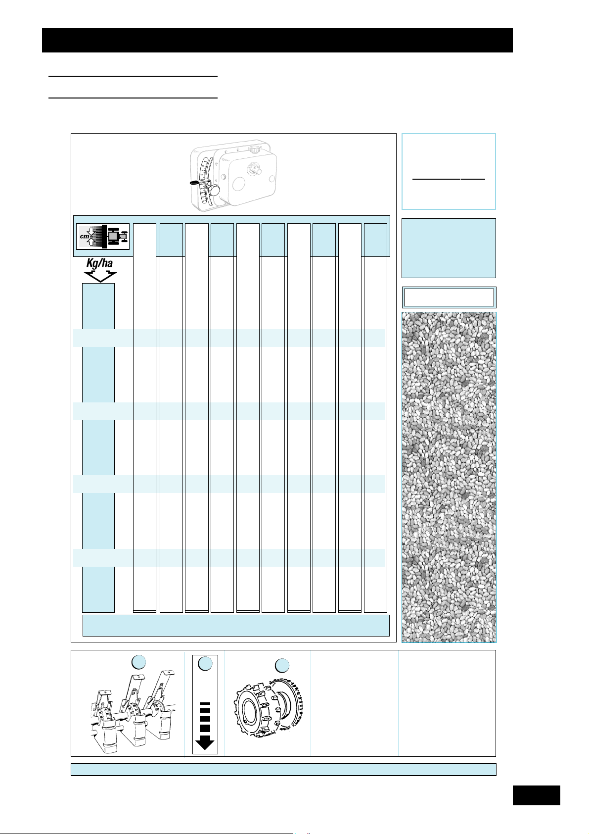
95
Tableaux de réglage
Setting charts
Einstelltabellen
L
UZERNE
M
ASTE
R
3
12 12,5 13 13,6 14 14,3 15 15,7 16 16,7
5
6
7
8
9
10
12
14
16
RÉF:
0
19 19 20 21 22 22 23 24 25 26
22 23 24 26 26 27 28 30 30 32
26 27 29 30 31 32 33 35 35 37
30 32 33 34 35 36 38 40 41 42
34 36 37 39 40 41 43 45 46 48
38 40 41 43 45 45 48 50 51 53
46 48 50 52 53 54 57 59 60 62
53 55 57 60 61 62 65 68 69 71
1
2
3
2
1
1
2
V
ARIÉTÉ
: C
ANNELLE
T
RAITEMENT
: -
 Loading...