

Page 1
3m
Notice Originale
Original Instructions
Originalbetriebsanleitung
A LIRE ATTENTIVEMENT AVANT D’UTILISER LA MACHINE
PLEASE READ CAREFULLY BEFORE USING THE MACHINE
VOR INBETRIEBNAHME SORGFÄLTIG LESEN!
Réf: 400 224-07 - FR-GB-DE /CV
Sulky Burel
BP 92111 - rue Fabien Burel
35221 Châteaubourg Cedex- FRANCE
Tél: 02.99.00.84.84 - Fax: 02.99.62.39.38
Site Internet : www.sulky-burel.com
e-mail : info@sulky-burel.com
Page 2

Page 3
Cher Utilisateur
le bon de
Garantie dûment rempli
J. BUREL
Dear Customer
Geehrter Kunde
Cher Client,
Vous avez choisi le kit Tramline SE, et nous vous
remercions de votre confiance pour notre matériel.
Pour une bonne utilisation, et pour tirer profit de toutes
les capacités de votre semoir, nous vous recommandons
de lire attentivement cette notice.
De par votre expérience, n’hésitez pas à nous faire part
de vos observations et suggestions, toujours utiles pour
l’amélioration de nos produits.
Nous vous saurions gré de nous retourner
.
En vous souhaitant bon usage de votre semoir,
Veuillez agréer, Cher Client, l’assurance de nos meilleurs
sentiments.
Président
GB
Dear Customer,
Thank you for choosing the kit Tramline SE.
To ensure correct operation, and to get the
most out of your seed drill, we recommend
that you read these instructions carefully.
Please do not hesitate to give us your
suggestions and comments based on your
experience. They are always useful for
improving our products.
We would be grateful if you could return
the duly completed guarantee coupon.
We hope your seed drill will provide long
and trouble-free service.
Yours sincerely.
DE
Geehrter Kunde,
Sie haben eine kit tramline SE - gewählt,
und wir danken Ihnen für das in unsere
Geräte gesetzte Vertrauen.
Bitte lesen Sie die Anleitung sorgfältig
durch, damit Sie ihre Drillmaschine richtig
benutzen und alle ihre Möglichkeiten voll
nutzen können.
Zögern Sie nicht, uns Ihre eigenen
Beobachtungen und Erfahrungen
mitzuteilen, die für die Verbesserung
unserer Produkte immer nützlich sein
können.
Garantieschein bitte ausgefüllt an uns
zurückschicken.
Wir wünschen Ihnen viel Erfolg mit Ihrem
Drillmaschine und verbleiben
mit freundlichen Grüßen
J. BUREL
Chairman
J. BUREL
Geschäftsführer
1
Page 4

Selon annexe 2, partie 1, point A de la directive « MACHINES » 2006/42/CE.
In accordance with Appendix 2, Section 1, Point A of the European Machinery Directive 2006/42/EC.
Gemäß Anhang II, Teil 1, Abschnitt A der Maschinenrichtlinie 2006/42/EG.
Déclaration de Conformité
Declaration of Conformity
Konformitätserklärung
NOM DU FABRICANT ET ADRESSE :
MANUFACTURER’S NAME AND ADDRESS:
NAME UND ADRESSE DES HERSTELLERS:
NOM DE LA PERSONNE AUTORISÉE A
CONSTITUER LE DOSSIER TECHNIQUE ET ADRESSE :
N
AME AND ADDRESS OF THE PERSON AUTHORISED
TO COMPILE THE TECHNICAL SPECIFICATIONS:
N
AME UND ADRESSE DES FÜR DIE ZUSAMMENSTELLUNG
DER TECHNISCHEN UNTERLAGEN BEVOLLMÄCHTIGTEN:
DESCRIPTION DE LA MACHINE :
MACHINE DESCRIPTION :
BESCHREIBUNG DER MASCHINE:
TYPE :
TYPE:
TYP:
NUMÉRO DE SÉRIE :
SERIAL NUMBER:
ERIENNUMMER:
S
SULKY-BUREL
BP 92111
35221 C
ACQUES
J
J
ACQUES
HÂTEAUBOURG CEDEX - FRANCE
BUREL
BUREL
BP 92111
35221 C
SEMOIR À GRAINS
SEMOIR À GRAINS
SEED DRILL
SEED DRILL
DRILLMASCHINE
DRILLMASCHINE
HÂTEAUBOURG CEDEX - FRANCE
KIT TRAMLINE SE
ACCESSOIRES :
ACCESSORIES:
ZUSATZAUSRÜSTUNGEN:
FR
LA MACHINE EST CONFORME AUX
DISPOSITIONS PERTINENTES DE LA
DIRECTIVE
A MACHINE EST CONFORME AUX
L
DISPOSITIONS DES AUTRES DIRECTIVES
SUIVANTES
IRECTIVE CEM 2004 / 108 / CE
D
Fait à Châteaubourg : Décembre 2009
Châteaubourg: December 2009
Ausgestellt in Châteaubourg: Dezember 2009
2
« MACHINES » 2006-42 CE
:
HE MACHINE CONFORMS TO THE
T
RELEVANT TERMS OF THE
EUROPEAN
MACHINERY DIRECTIVE 2006/42/EC.
HE MACHINE ALSO CONFORMS TO THE
T
TERMS OF THE FOLLOWING DIRECTIVES
IRECTIVE CEM 2004/108/EC
D
GB
IE MASCHINE ENTSPRICHT ALLEN
D
EINSCHLÄGIGEN
BESTIMMUNGEN DER
MASCHINENRICHTLINIE 2006/42/EG
IE MASCHINE ENTSPRICHT
D
:
BESTIMMUNGEN
DEN
DER NACHFOLGENDEN
EMV-R
ICHTLINIE 2004/108/EG
Signé :
Signed:
Unterzeichnet:
J. BUREL
Président
Chairman
Geschäftsführer
DE
RICHTLINIEN:
Page 5

PRESCRIPTIONS GÉNÉRALES DE SÉCURITÉ
GÉNÉRALITÉS
UTILISATION CONFORME DE LA MACHINE
ATTELAGE
Prescriptions de sécurité
FR
Risque d’accident
Ces symboles sont utilisés dans cette notice chaque fois que des recommandations concernent votre sécurité, celle d’autrui ou le bon
fonctionnement de la machine.
Transmettez impérativement ces recommandations à tout utilisateur de la machine.
Avant chaque utilisation et mise en service de
l’ensemble tracteur-machine, s’assurer de sa
conformité avec la réglementation en matière de
sécurité du travail et avec les dispositions du Code
de la Route.
1 - Respecter, en plus des instructions contenues
dans cette notice, la législation relative aux
prescriptions de sécurité et de prévention des
accidents.
2 - Les avertissements apposés sur la machine
fournissent des indications sur les mesures de
sécurité à observer et contribuent à éviter les
accidents.
3 - Lors de la circulation sur la voie publique,
respecter les prescriptions du Code de la Route.
4 - Avant de commencer le travail, l’utilisateur
devra se familiariser obligatoirement avec les
organes de commande et de manœuvre de la
machine et leurs fonctions respectives. En cours
de travail, il sera trop tard pour le faire.
5 - L’utilisateur doit éviter de porter des vêtements
flottants qui risqueraient d’être happés par des
éléments en mouvement.
6 - Il est recommandé d’utiliser un tracteur équipé
d’une cabine ou d’un arceau de sécurité, aux
normes en vigueur.
7 - Avant la mise en route de la machine et le
démarrage des travaux, contrôler les abords
immédiats (enfant !).
Veiller à avoir une visibilité suffisante ! Eloigner
toute personne ou animal de la zone de danger de
la machine (projections !).
8 - Le transport de personnes ou d’animaux sur la
machine lors du travail ou lors des déplacements
est strictement interdit.
9 - L’accouplement de la machine au tracteur ne
doit se faire que sur les points d’attelage prévus à
cet effet conformément aux normes de sécurité
en vigueur.
10 - La prudence est de rigueur lors de l’attelage
de la machine au tracteur et lors de son
désaccouplement !
11 - Avant d’atteler la machine, il conviendra de
s’assurer que le lestage de l’essieu avant du
tracteur est suffisant. La mise en place des masses
de lestage doit se faire sur les supports prévus à
cet effet conformément aux prescriptions du
constructeur du tracteur.
12 - Respecter la charge à l’essieu maximum et le
poids total roulant autorisé en charge.
13 - Respecter le gabarit maximum sur la voie
publique.
Risque d’endommager la machine
14 - Avant de s’engager sur la voie publique,
veiller à la mise en place et au bon
fonctionnement des protecteurs et dispositifs de
signalisation (lumineux, réfléchissants…) exigés
par la loi.
15 - Toutes les commandes à distance (corde,
câble, tringle, flexible…) doivent être positionnées
de telle sorte qu’elles ne puissent déclencher
accidentellement une manœuvre génératrice de
risque d’accident ou de dégâts.
16 - Avant de s’engager sur la voie publique,
placer la machine en position de transport,
conformément aux indications du constructeur.
17 - Ne jamais quitter le poste de conduite
lorsque le tracteur est en marche.
18 - La vitesse et le mode de conduite doivent
toujours être adaptés aux terrains, routes et
chemins. En toute circonstance, éviter les
brusques changements de direction.
19 - La précision de la direction, l’adhérence du
tracteur, la tenue de route et l’efficacité des
dispositifs de freinage sont influencées par des
facteurs tels que : poids et nature de la machine
attelée, lestage de l’essieu avant, état du terrain ou
de la chaussée. Il est donc impératif de veiller au
respect des règles de prudence dictées par
chaque situation.
20 - Redoubler de prudence dans les virages en
tenant compte du porte-à-faux, de la longueur, de
la hauteur et du poids de la machine ou de la
remorque attelée.
21 - Avant toute utilisation de la machine,
s’assurer que tous les dispositifs de protection
sont en place et en bon état. Les protecteurs
endommagés doivent être immédiatement
remplacés.
22 - Avant chaque utilisation de la machine,
contrôler le serrage des vis et des écrous, en
particulier de ceux qui fixent les outils (disques,
palettes, déflecteurs…). Resserrer si nécessaire.
23 - Ne pas stationner dans la zone de manœuvre
de la machine.
24 - Attention ! Des zones d’écrasement et de
cisaillement peuvent exister sur les organes
commandés à distance, notamment ceux asservis
hydrauliquement.
25 - Avant de descendre du tracteur, ou
préalablement à toute intervention sur la machine,
couper le moteur, retirer la clé de contact et
attendre l’arrêt complet de toutes les pièces en
mouvement.
26 - Ne pas stationner entre le tracteur et la
machine sans avoir préalablement serré le frein de
parcage et/ou avoir placé des cales sous les
roues.
27 - Avant toute intervention sur la machine,
s’assurer que celle-ci ne puisse être mise en route
accidentellement.
28 - Ne pas utiliser l’anneau de levage pour lever
la machine lorsqu’elle est remplie.
Le kit ne doit être utilisé que pour les travaux pour
lesquels il a été conçu.
En cas de dommage lié à l’utilisation de la
machine hors du cadre des applications spécifiées
par le constructeur, la responsabilité de celui-ci
sera entièrement dégagée.
Toute extrapolation de la destination d’origine de la
machine se fera aux risques et périls de
l’utilisateur.
L’utilisation conforme de la machine implique
également :
- le respect des prescriptions d’utilisation,
d’entretien et de maintenance édictées par le
constructeur,
- l’utilisation exclusive de pièces de rechange,
d’équipements et d’accessoires d’origine ou
préconisés par le constructeur.
Le kit ne doit être utilisé, entretenu et réparé que
par des personnes compétentes, familiarisées avec
les caractéristiques et modes d’utilisation de la
machine. Ces personnes doivent aussi être
informées des dangers auxquels elles pourraient
être exposées.
L’utilisateur est tenu au respect scrupuleux de la
réglementation en vigueur en matière de :
- prévention contre les accidents,
- sécurité du travail (Code du Travail),
- circulation sur la voie publique (Code de la
Route).
- Il lui est fait obligation d’observer strictement les
avertissements apposés sur la machine.
- Toute modification de la machine effectuée par
l’utilisateur lui-même ou toute autre personne,
sans l’accord écrit préalable du constructeur
engagera la responsabilité du propriétaire du
matériel modifié.
- Le bruit créé par la machine n’excède pas 70
décibels.
1 - Lors de l’attelage de la machine au tracteur ou
de sa dépose, placer le levier de commande du
relevage hydraulique dans une position telle que
toute entrée en action du relevage ne puisse
intervenir de façon inopinée.
2 - Lors de l’attelage de la machine au relevage 3
points du tracteur, veiller à ce que les diamètres
des broches ou tourillons correspondent bien aux
diamètres des rotules du tracteur.
3 - Attention ! Dans la zone de relevage 3 points,
il existe des risques d’écrasement et de
cisaillement!
Faciliter le travail
3
Page 6

FR
4 - Ne pas se tenir entre le tracteur et la machine
lors de la manœuvre du levier de commande
extérieur du relevage.
5 - Au transport la machine doit être stabilisée par
les tirants de rigidification du relevage pour éviter
tout flottement et débattement latéral.
6 - Lors du transport de la machine en position
relevée, verrouiller le levier de commande du
relevage.
7 - Ne jamais dételer la machine lorsque la trémie
est remplie.
ORGANES D’ANIMATION
(Prises de force et arbres de transmission à
cardans)
1 - N’utiliser que les arbres de transmission à
cardans fournis avec la machine ou préconisés par
le constructeur.
2 - Les protecteurs des prises de force et des
arbres de transmission à cardans doivent toujours
être en place et en bon état.
3 - Veiller au recouvrement correct des tubes des
arbres de transmission à cardans, aussi bien en
position de travail qu’en position de transport.
4 - Avant de connecter ou de déconnecter un
arbre de transmission à cardans, débrayer la prise
de force, couper le moteur et retirer la clé de
contact.
5 - Si l’arbre de transmission à cardans primaire
est équipé d’un limiteur de couple ou d’une roue
libre, ceux-ci doivent impérativement être montés
sur la prise de force de la machine.
6 - Veiller toujours au montage et au verrouillage
corrects des arbres de transmission à cardans.
7 - Veiller toujours à ce que les protecteurs des
arbres de transmission à cardans soient
immobilisés en rotation à l’aide des chaînettes
prévues à cet effet.
8 - Avant d’embrayer la prise de force, s’assurer
que le régime choisi et le sens de rotation de la
prise de force sont conformes aux prescriptions du
constructeur.
9 - Avant d’embrayer la prise de force, s’assurer
qu’aucune personne ou animal ne se trouve à
proximité de la machine.
10 - Débrayer la prise de force lorsque les limites
de l’angle de l’arbre de transmission à cardans
prescrites par le constructeur risquent d’être
dépassées.
11 - Attention ! Après le débrayage de la prise de
force, les éléments en mouvement peuvent
continuer à tourner quelques instants encore. Ne
pas s’en approcher avant immobilisation totale.
12 - Lors de la dépose de la machine, faire
reposer les arbres de transmission à cardans sur
les supports prévus à cet effet.
13 - Après avoir déconnecté l’arbre de
transmission à cardans de la prise de force du
tracteur, celle-ci doit être recouverte de son
capuchon protecteur.
14 - Les protecteurs de prise de force et d’arbres
de transmission à cardans endommagés doivent
être remplacés immédiatement.
CIRCUIT HYDRAULIQUE
1 - Attention ! Le circuit hydraulique est sous
pression.
2 - Lors du montage de vérins ou de moteurs
hydrauliques, veiller attentivement au branchement
correct des circuits, conformément aux directives
du constructeur.
3 - Avant de brancher un flexible au circuit
hydraulique du tracteur, s’assurer que les circuits
côté tracteur et côté machine ne sont pas sous
pression.
4 - Il est vivement recommandé à l’utilisateur de la
machine de suivre les repères d’identification sur
les raccords hydrauliques entre le tracteur et la
machine afin d’éviter des erreurs de branchement.
Attention ! Il y a risque d’interversion des fonctions
(par exemple : relever/abaisser).
5 - Contrôler une fois par an les flexibles
hydrauliques :
. Blessure de la couche extérieure
. Porosité de la couche extérieure
. Déformation sans pression et sous pression
. Etat des raccords et des joints
La durée d’utilisation maximum des flexibles est de
6 ans. Lors de leur remplacement, veiller à n’utiliser
que des flexibles de caractéristiques et de qualité
prescrits par le constructeur de la machine.
6 - Lors de la localisation d’une fuite, il conviendra
de prendre toute précaution visant à éviter les
accidents.
7 - Tout liquide sous pression, notamment l’huile
du circuit hydraulique peut perforer la peau et
occasionner de graves blessures ! En cas de
blessure, consulter de suite un médecin ! Il y a
danger d’infection !
8 - Avant toute intervention sur le circuit
hydraulique, abaisser la machine, mettre le circuit
hors pression, couper le moteur et retirer la clé de
contact.
ENTRETIEN
1 - Avant tous travaux de maintenance, d’entretien
ou de réparation, ainsi que lors de la recherche de
l’origine d’une panne ou d’un incident de
fonctionnement, il faut impérativement que la prise
de force soit débrayée, que le moteur soit coupé
et la clé de contact retirée.
2 - Contrôler régulièrement le serrage des vis et
des écrous. Resserrer si nécessaire !
3 - Avant de procéder à des travaux d’entretien
sur une machine en position relevée, étayer celleci à l’aide d’un moyen approprié.
4 - Lors du remplacement d’une pièce travaillante,
(pale pour les distributeurs ou socs pour les
semoirs), mettre des gants de protection et
n’utiliser qu’un outillage approprié.
5 - Pour la protection de l’environnement, il est
interdit de jeter ou de déverser les huiles, graisses
et filtres en tout genre. Les confier à des
entreprises spécialisées dans leur récupération.
6 - Avant toute intervention sur le circuit
électrique, déconnecter la source d’énergie.
7 - Les dispositifs de protection susceptibles
d’être exposés à une usure doivent être contrôlés
régulièrement. Les remplacer immédiatement s’ils
sont endommagés.
8 - Les pièces de rechange doivent répondre aux
normes et caractéristiques définies par le
constructeur. N’utiliser que des pièces de
rechange Sulky !
9 - Avant d’entreprendre des travaux de soudure
électrique sur le tracteur ou la machine attelée,
débrancher les câbles de l’alternateur et de la
batterie.
10 - Les réparations affectant les organes sous
tension ou pression (ressorts, accumulateurs de
pression, etc) impliquent une qualification
suffisante et font appel à un outillage spécifique ;
aussi ne doivent-elles être effectuées que par un
personnel qualifié.
4
Page 7

GENERAL SAFETY REGULATIONS
GENERAL
PROPER USE OF THE MACHINE
HITCHING
DRIVE EQUIPMENT
Safety regulations
GB
Risk of accident
These symbols are used in these instructions every time recommendations are provided concerning your safety, the safety of others or the
correct operation of the machine.
These recommendations must be given to all users of the machine.
Every time the tractor/machine assembly is to be
started up and used, you should ensure
beforehand that it complies with current legislation
on safety at work and Road Traffic regulations.
1 - In addition to the instructions contained in this
manual, legislation relating to safety instructions
and accident prevention should be complied with.
2 - Warnings affixed to the machine give
indications regarding safety measures to be
observed and help to avoid accidents.
3 - When travelling on public roads, abide by the
provisions of the Highway Code.
4 - Before starting work, it is essential that the
user familiarizes himself with the control and
operating elements of the machine and their
respective functions. When the machine is
running, it may be too late.
5 - The user should avoid wearing loose clothing
which may be caught up in the moving parts.
6 - We recommend using a tractor with a safety
cab or roll bar conforming to standards in force.
7 - Before starting up the machine and beginning
work, check the immediate surroundings,
particularly for children. Make sure that visibility is
adequate. Clear any persons or animals out of the
danger zone.
8 - It is strictly forbidden to transport any persons
or animals on board the machine whether it is in
operation or not.
9 - The machine should only be coupled up to the
tractor at the specially provided towing points and
in accordance with applicable safety standards.
10 - Extreme care must be taken when coupling
or uncoupling the machine from the tractor.
11 - Before hitching up the machine, ensure that
the front axle of the tractor is sufficiently
weighted. Ballast weights should be fitted to the
special supports in accordance with the
instructions of the tractor manufacturer.
12 - Do not exceed the maximum axle weight or
the gross vehicle weight rating.
13 - Do not exceed the maximum authorized
dimensions for using public roads.
14 - Before entering a public road, ensure that
the protective and signalling devices (lights,
reflectors, etc.) required by law are fitted and
working properly.
15 - All remote controls (cords, cables, rods,
hoses, etc.) must be positioned so that they
cannot accidentally set off any manoeuvre which
may cause an accident or damage.
16 - Before entering a public road, place the
machine in the transport position, in accordance
Risk of damage to the machine
with the manufacturer’s instructions.
17 -. Never leave the driver’s position whilst the
tractor is running.
18 - The speed and the method of operation must
always be adapted to the land, roads and paths.
Avoid sudden changes of direction under all
circumstances.
19 - Precision of the steering, tractor adhesion,
road holding and effectiveness of the braking
mechanism are influenced by factors such as the
weight and nature of the machine being towed,
the front axle stage and the state of the land or
path. It is essential, therefore, that the appropriate
care is taken for each situation.
20 - Take extra care when cornering, taking
account of the overhang, length, height and
weight of the machine or trailer being towed.
21 - Before using the machine, ensure that all
protective devices are fitted and in good condition.
Damaged protectors should be replaced
immediately.
22 - Before using the machine, check that nuts
and screws are tight, particularly those for
attaching tools (discs, flickers, deflectors, etc.).
Tighten if necessary.
23 - Do not stand in the operating area of the
machine.
24 - Caution! Be aware of any crushing and
shearing zones on remote-controlled and
particularly hydraulically-controlled parts.
25 - Before climbing down from the tractor, or
before any operation on the machine, turn off the
engine, remove the key from the ignition and wait
until all moving parts have come to a standstill.
26 - Do not stand between the tractor and the
machine until the handbrake has been applied
and/or the wheels have been wedged.
27 -. Before any operation on the machine, ensure
that it
cannot be started up accidentally.
28 - Do not use the lifting ring to lift the machine
when it is loaded.
The kit must only be used for the purpose for
which it was designed.
The manufacturer will not be liable for any damage
caused by using the machine for applications
other than those specified by the manufacturer.
Using the machine for purposes other than those
originally intended will be done so entirely at the
user’s risk.
Proper use of the machine also implies:
- complying with instructions on use, care and
maintenance provided by the manufacturer;
- using only original or manufacturer
recommended spare parts, equipment and
accessories.
The Kit must only be operated, maintained and
repaired by competent persons, familiar with the
specifications and methods of operation of the
machine. These persons must also be informed of
the dangers to which they may be exposed.
The user must strictly abide by current legislation
regarding:
- accident prevention;
- safety at work (Health and Safety Regulations);
- transport on public roads (Road Traffic
Regulations).
Strict compliance with warnings affixed to the
machine is obligatory.
The owner of the equipment shall become liable
for any damage resulting from alterations made to
the machine by the user or any other person,
without the prior written consent of the
manufacturer.
The noise created by the machine does not
exceed 70 decibels.
1 - When hitching or unhitching the machine from
the tractor, place the control lever of the hydraulic
lift in such a position that the lifting mechanism
cannot be activated accidentally.
2 - When hitching the machine to the three-point
lifting mechanism of the tractor, ensure that the
diameters of the pins or gudgeons correspond to
the diameter of the tractor ball joints.
3 - Caution! In the three-point lifting zone, there
may be a danger of crushing and shearing.
4 - Do not stand between the tractor and the
machine whilst operating the external lift control
lever.
5 - When in transport, lifting mechanism stabilizer
bars must be fitted to the machine to avoid
floating and side movement.
6 - When transporting the machine in the raised
position, lock the lift control lever.
7 - Never unhitch the machine when the hopper
is full.
(Power take-off and universal drive shafts)
1 - Only use universal drive shafts supplied with
the machine or recommended by the
manufacturer.
2 - Power take-off and universal drive shaft
guards must always be fitted and in good
condition.
Operating tip
5
Page 8

HYDRAULIC CIRCUIT
MAINTENANCE
GB
3 - Ensure that the tubes of the universal drive
shafts are properly guarded, both in the working
position and in the transport position.
4 - Before connecting or disconnecting a universal
drive shaft, disengage the power take-off, turn off
the engine and re-move the key from the ignition.
5 - If the primary universal drive shaft is fitted with
a torque limiter or a free wheel, these must be
mounted on the machine power take-off.
6 - Always ensure that universal drive shafts are
fitted and locked correctly.
7 - Always ensure that universal drive shaft guards
are immobilized in rotation using the specially
provided chains.
8 - Before engaging power take-off, ensure that
the speed selected and the direction of rotation of
the power take-off comply with the
manufacturer’s instructions.
9 - Before engaging power take-off, ensure that
no persons or animals are close to the machine.
10 - Disengage power take-off when the universal
drive shaft angle limits laid down by the
manufacturer are in danger of being exceeded.
11 - Caution! When power take-off has been
disengaged, moving parts may continue to rotate
for a few moments. Do not approach until they
have reached a complete standstill.
12 - On removal from the machine, rest the
universal drive shafts on the specially provided
supports.
13 - After disconnecting the universal drive shafts
from the power take-off, the protective cap should
be fitted to the power take-off.
14 - Damaged power take-off and universal drive
shaft guards must be replaced immediately.
1 - Caution! The hydraulic circuit is pressurized.
2 - When fitting hydraulic motors or cylinders,
ensure that the circuits are connected correctly in
accordance with the manufacturer’s guidelines.
3 - Before fitting a hose to the tractor’s hydraulic
circuit, ensure that the tractor-side and machineside circuits are not pressurized.
4 - The user of the machine is strongly
recommended to identify the hydraulic couplings
between the tractor and the machine in order to
avoid wrong connection. Caution! There is a
danger of reversing the functions (for example:
raise/lower).
5 - Check hydraulic hoses once a year:
. Damage to the outer surface
. Porosity of the outer surface
. Deformation with and without pressure
. State of the fittings and seals
The maximum working life for hoses is 6 years.
When replacing them, ensure that only hoses with
the specifications and grade recommended by the
machine manufacturer are used.
6 - When a leak is found, all necessary
precautions should be taken to avoid accidents.
7 - Pressurized liquid, particularly hydraulic circuit
oil, may cause serious injury if it comes into
contact with the skin. If the case of injury, consult
a doctor immediately. There is a risk of infection.
8 - Before any operation on the hydraulic circuit,
lower the machine, release the pressure from the
circuit, turn off the engine and remove the key
from the ignition.
1 - Before commencing any maintenance,
servicing or repair work, or before attempting to
locate the source of a breakdown or fault, it is
essential that the power take-off is disengaged,
the engine turned off and the key removed from
the ignition.
2 - Check regularly that nuts and screws are not
loose. Tighten if necessary.
3 - Before carrying out maintenance work on a
raised machine, prop it up using appropriate
means of support.
4 - When replacing a working part (fertilizer
spreader blade or seed drill coulter), wear
protective gloves and only use appropriate tools.
5 - To protect the environment, it is forbidden to
throw away oil, grease or filters of any kind. Give
them to specialist recycling firms.
6 - Before operating on the electric circuit,
disconnect the power source.
7 - Protective devices likely to be exposed to wear
and tear should be checked regularly. Replace
them immediately if they are damaged.
8 - Spare parts should comply with the standards
and specifications laid down by the manufacturer.
Only use Sulky spare parts.
9 - Before commencing any electric welding work
on the tractor or the towed machine, disconnect
the alternator and battery cables.
10 - Repairs affecting parts under stress or
pressure (springs, pressure accumulators, etc.)
should be carried out by suitably qualified
engineers with special tools.
6
Page 9

ALLGEMEINE SICHERHEITSVORSCHRIFTEN
ALLGEMEINES
BESTIMMUNGSGEMÄßE VERWENDUNG DER
MASCHINE
ANHÄNGUNG
Sicherheitsvorschriften
DE
Verletzungsgefahr
In der Anweisung werden diese Zeichen in Verbindung mit Empfehlungen für Ihre Sicherheit und der anderer sowie die gute Funktion der
Maschine verwendet.
Jeder Benutzer dieser Maschine muß diese Vorschriften genau kennen.
Vor jeder Benutzung und Inbetriebsetzung der
Schlepper-Maschine-Einheit kontrollieren, ob sie
den Sicherheitsvorschriften und den Vorschriften
der Straßenverkehrsordnung entsprechen.
1 - Zusätzlich zu den in diesem Handbuch
enthaltenen Anweisungen die Gesetzgebung
bezüglich der Sicherheits- und
Unfallverhütungvorschriften einhalten.
2 - Die auf der Maschine angebrachten
Warnungen informieren über die einzuhaltenden
Sicherheitsmaßnahmen und tragen zur
Unfallverhütung bei.
3 - Im Straßenverkehr die
Straßenverkehrsordnung einhalten.
4 - Vor Arbeitsbeginn muß sich der Benutzer
unbedingt mit den Antriebs- und
Bedienungsorganen der Maschine und ihren
jeweiligen Funktionen vertraut machen. Während
der Arbeit ist es dafür zu spät.
5 - Weite Kleidungsstücke, die in sich bewegende
Teile geraten könnten, vermeiden.
6 - Es empfiehlt sich, gemäß den gültigen Normen
einen Schlepper mit Kabine oder
Sicherheitsverstärkung zu verwenden.
7 - Vor Inbetriebsetzung und Arbeitsbeginn die
direkte Umgebung kontrollieren (Kind !). Für
ausreichende Sicht sorgen! Personen oder Tiere
aus dem Maschinengefahrenbereich entfernen
(Schutzvorrichtungen !).
8 - Der Transport von Personen oder Tieren auf
der Maschine ist während der Arbeit oder beim
Fahren streng verboten.
9 - Die Maschine darf gemäß den geltenden
Sicherheitsnormen nur an den dafür vorgesehenen
Kupplungspunkten angehängt werden.
10 - Besondere Vorsicht ist beim An- und Abbau
der Maschine am Schlepper geboten.
11 - Vor Anhängen der Maschine kontrollieren, ob
der Ballast des Schleppers genügt. Die
Ballastelemente müssen gemäß den Vorschriften
des Schlepperherstellers auf den dafür
vorgesehenen Haltern angebracht werden.
12 - Die maximale Achslast und das zulässige
Gesamtgewicht einhalten.
13 - Das für den Straßenverkehr maximal
zulässige Außenmaß einhalten.
14 - Vor Straßenbenutzung die
Schutzvorrichtungen und
Signalisierungsvorrichtungen (Licht- und
Rückstrahlelemente) anbringen und ihre Funktion
prüfen.
Gefahr der Beschädigung der Maschine
15 - Alle Fernsteuerungen (Seil, Kabel, Stange,
Schlauch) müssen so positioniert sein, daß sie
nicht ungewollt betätigt werden und dadurch
Unfälle oder Schäden hervorrufen können.
16 - Vor Benutzung der Straße die Maschine
gemäß Herstelleranweisungen in Transportstellung
bringen.
17 -. Fahrersitz nie bei laufender Maschine
verlassen.
18 - Fahrgeschwindigkeit und -weise müssen
immer dem Gelände, den Straßen und Wegen
angepaßt sein. Auf alle Fälle plötzliche
Richtungsänderungen vermeiden.
19 - Die Präzision der Lenkung, die Bodenhaftung
des Schleppers, die Straßenlage und die
Wirksamkeit der Bremsvorrichtungen werden
beeinflußt von Faktoren wie: Gewicht und Art der
angebauten Maschine, Belastung der Vorderachse,
Zustand des Geländes oder der Fahrbahn. Die den
Bedingungen entsprechenden
Vorsichtsmaßnahmen einhalten.
20 - Besondere Vorsicht ist in Kurven geboten.
Schwerpunktlage, Länge, Höhe und Gewicht der
Maschine oder des Anhängers berücksichtigen.
21 - Vor jeder Benutzung der Maschine
kontrollieren, ob alle Schutzvorrichtungen
angebracht und in gutem Zustand sind. Bei
Beschädigung sofort austauschen.
22 - Vor jeder Benutzung kontrollieren, ob alle
Schrauben und Muttern fest angezogen sind,
insbesondere die, mit denen die Geräte befestigt
sind (Scheiben, Paletten, Schirme...). Notfalls
anziehen.
23 - Sich nicht im Manövrierbereich der Maschine
aufhalten.
24 - Vorsicht! Auf den Fernsteuerungsorganen,
insbesondere auf denen mit hydraulischem
Regelkreis, kann es Stauch- und Abscherzonen
geben.
25 - Vor Verlassen des Schleppers oder vor jedem
Eingriff auf der Maschine Motor abschalten,
Zündschlüssel abziehen und völligen Stillstand
aller bewegten Teile abwarten.
26 - Sich nicht zwischen Schlepper und Maschine
aufhalten, ohne zuvor die Parkbremse angezogen
und/oder Keile unter die Räder gelegt zu haben.
27 - Vor jedem Eingriff an der Maschine
kontrollieren, ob diese nicht ungewollt in Betrieb
gesetzt werden kann.
28 - Die Aufhängöse nicht zum Heben der
gefüllten Maschine benutzen.
Der Bausatz sollte nur für die Arbeiten verwendet
werden, für die er konzipiert wurde.
Hinweis zur Erleichterung der Arbeit
Bei Beschädigung der Maschine infolge einer
nicht vom Hersteller spezifizierten Benutzung ist
dieser nicht haftbar.
Jede nicht der ursprünglichen Bestimmung der
Maschine entsprechende Benutzung erfolgt auf
Rechnung und Gefahr des Benutzers.
Die bestimmungsgemäße Verwendung der
Maschine setzt ebenfalls voraus:
- die Einhaltung der vom Hersteller verordneten
Benutzungs-, Wartungs- und
Instandsetzungsvorschriften,
- die ausschließliche Verwendung von
Originalersatzteilen, Originalausrüstungen und
Originalzubehör oder von Teilen, die vom Hersteller
empfohlen sind.
Die Kit darf nur von kompetenten, mit den
technischen Daten und Benutzungsanweisungen
der Maschine vertrauten Personen benutzt,
gewartet und repariert werden, die über die
Risiken informiert sind, denen sie ausgesetzt sein
könnten.
Streng die gültige Reglementierung einhalten
bezüglich:
- der Unfallverhütung,
- der Arbeitssicherheit (Arbeitsgesetzbuch)
- des Straßenverkehrs (Straßenverkehrsordnung).
Die auf der Maschine angebrachten Warnungen
berücksichtigen.
Der Hersteller haftet nicht für Schäden, die durch
Abänderungen entstehen, die vom Benutzer selbst
oder von Dritten ohne schriftliche Genehmigung
an der Maschine vorgenommen wurden.
Das von der Maschine hervorgerufene Geräusch
liegt unter 70 Dezibel.
1 - Beim An- und Abkuppeln der Maschine am
Schlepper, den Steuerhebel des
Hydraulikkrafthebers so stellen, daß der Hubvorgang nicht unerwartet ausgelöst werden kann.
2 - Beim Anhängen der Maschine am
Dreipunktkraftheber des Schleppers darauf
achten, daß die Spindel- oder Zapfendurchmesser
dem Durchmesser der Schlepperkugelgelenke
entsprechen.
3 - Vorsicht! Im Dreipunkt-Hubbereich bestehen
Stauch- und Abscherrisiken!
4 - Sich bei Betätigung des äußeren KraftheberSteuerhebels nicht zwischen Schlepper und
Maschine aufhalten.
5 - Beim Transport muß die Maschine durch die
Versteifungsstreben des Krafthebers zur
Vermeidung von Unwucht und seitlicher
Pendelung stabilisiert werden.
6 - Beim Transport der Maschine in angehobener
Stellung den Kraftheber-Steuerhebel blockieren.
7
Page 10

ANTRIEBSORGANE
HYDRAULIKLEITUNG
WARTUNG
DE
7 - Die Maschine erst abhängen wenn der Tank
leer ist.
(Zapfwelle und Gelenkwellen-Antrieb)
1 - Nur die mit der Maschine gelieferte oder vom
Konstrukteur empfohlene Gelenkwelle verwenden.
2 - Die Schutzvorrichtungen der Zapfwellen und
Gelenkwellen müssen immer angebracht und in
gutem Zustand sein.
3 - Auf die richtige Überlappung der
Gelenkwellenrohre sowohl in Arbeits- als auch in
Transportstellung achten.
4 - Vor Anschließen oder Abziehen einer
Gelenkwelle die Zapfwelle auskuppeln, den Motor
abschalten und den Zündschlüssel abziehen.
5 - Ist die Primärkardanwelle mit einem
Drehmomentbegrenzer oder einer
Freilaufkupplung ausgestattet, müssen diese
unbedingt auf der Zapfwelle der Maschine
montiert sein.
6 - Immer auf die korrekte Montage und
Verriegelung der Kardanantriebe achten.
7 - Immer darauf achten, daß die
Schutzvorrichtungen der Gelenkwellen mit den
dafür vorgesehenen Ketten gegen Verdrehen
gesichert sind.
8 - Vor Kuppeln der Zapfwelle prüfen, ob die
gewählte Drehzahl und die Drehrichtung der
Zapfwelle den Vorschriften des Herstellers
entsprechen.
9 - Vor Kuppeln der Zapfwelle kontrollieren, ob
sich keine Personen oder Tiere in Nähe der
Maschine befinden.
10 - Die Zapfwelle auskuppeln, wenn Gefahr
besteht, daß die vom Hersteller vorgeschriebenen
Grenzen des Gelenkwellenwinkels überschritten
werden.
11 - Vorsicht! Nach Auskuppeln der Zapfwelle
können Teile der Maschine noch einige Zeit
nachlaufen. Sich ihnen nie vor völligem Stillstand
nähern.
12 - Bei Abbau der Maschine die Gelenkwellen
auf den dafür vorgesehenen Haltern ablegen.
13 - Nach Abziehen der Gelenkwelle von der
Schlepperzapfwelle muß diese mit ihrer
Schutzkappe bedeckt werden.
14 - Schadhafte Schutzvorrichtungen der
Zapfwelle und der Gelenkwelle müssen sofort
ausgewechselt werden.
1 - Vorsicht! Die Hydraulikleitung steht unter
Druck.
2 - Bei Montage von Zylindern oder
Hydraulikmotoren auf den korrekten Anschluß
gemäß Anweisungen des Herstellers achten.
3 - Vor Anschluß eines Schlauches an der
Hydraulikleitung des Schleppers dafür sorgen, daß
die schlepper- und maschinenseitigen Leitungen
nicht unter Druck stehen.
4 - Dem Benutzer der Maschine wird zur
Vermeidung falscher Anschlüsse dringend geraten,
die Kennzeichnungen auf den
Hydraulikanschlüssen zwischen Schlepper und
Maschine zu beachten, da sonst die Gefahr einer
Funktionsumkehrung besteht. (z.B.:
Heben/Senken).
5 - Einmal im Jahr die Hydraulikschläuche
kontrollieren auf:
. Beschädigung der Außenschicht
. Porosität der Außenschicht
. Verformung ohne Druck und unter Druck
. Zustand der Verbindungen und Dichtungen.
Die maximale Benutzungsdauer der Schläuche ist
6 Jahre. Beim Auswechseln darauf achten, daß
nur Schläuche verwendet werden, deren
Eigenschaften und Qualität den Vorschriften des
Maschinenkonstrukteurs entsprechen.
6 - Bei Feststellung einer undichten Stelle alle
Vorsichtsmaßnahmen zur Unfallverhütung treffen.
7 - Eine unter Druck stehende Flüssigkeit,
insbesondere das Öl der Hydraulikleitung, kann die
Haut durchdringen und schwere Verletzungen
verursachen! Bei Verletzungen sofort Arzt
konsultieren; Infektionsgefahr!
8 - Vor jedem Eingriff in die Hydraulikanlage
Maschine ablassen, Anlage drucklos schalten,
Motor abstellen und Zündschlüssel abziehen.
1 - Vor Instandsetzungs-, Wartungs- oder
Reparaturarbeiten sowie bei Ermitteln einer
Pannen- oder Betriebsstörungsquelle muß die
Zapfwelle ausgekuppelt, der Motor abgeschaltet
und der Zündschlüssel abgezogen sein.
2 - Regelmäßig kontrollieren, ob Schrauben und
Muttern fest angezogen sind. Notfalls anziehen.
3 - Vor Wartung einer Maschine in angehobener
Stellung diese mit einem geeigneten Mittel
abstützen.
4 - Beim Austausch eines Funktionsteiles
(Schaufel bei Streuern oder Schare bei
Drillmaschinen) Schutzhandschuhe tragen und nur geeignete Werkzeuge
benutzen.
5 - Zum Schutz der Umwelt ist es verboten, Öl,
Fett und Filter jeder Art wegzuwerfen oder
auszugießen. Sie sind von darauf spezialisierten
Unternehmen zu entsorgen.
6 - Vor Eingriff an der elektrischen Leitung die
Stromzufuhr unterbrechen.
7 - Verschleiß ausgesetzte Schutzvorrichtungen
müssen regelmäßig kontrolliert werden. Sie sofort
austauschen, wenn schadhaft.
8 - Ersatzteile müssen den vom Konstrukteur
festgelegten Normen und Kennwerten
entsprechen. Nur Sulky-Ersatzteile verwenden!
9 - Vor Elektroschweißarbeiten am Schlepper oder
der angehängten Maschine die Kabel des
Wechselstromgenerators und der Batterie
abziehen.
10 - Reparaturen an Organen, die unter Spannung
oder Druck stehen (Federn, Druckspeicher, usw...)
setzen eine ausreichende Qualifikation voraus und
erfordern Werkzeuge; sie dürfen daher nur von
qualifiziertem Personal durchgeführt werden.
8
Page 11

SOMMAIRE
Français
Pages
MISE EN ROUTE
1
13
12-13
14-15
20-21
20-21
22-23
Pages
26-35
36-37
36-37
Pages
38-39
38-39
38-39
40-41
42-43
44-45
• A Préparation de la machine
• B Manutention
• C Contrôle tracteur
• D Montage de la trémie
• E Montage des tuyaux de
transport
• F Montage du bras de roue
REGLAGES
• A Réglage du débit
• B Débrayage demi-semoir
• C Vidange de la trémie
ENTRETIEN
• A Entretien
• B Graissage
• C Vérification
• D Distribution
• E Caractéristiques techniques
• F Positions Autocollants
24-25 • G Montage de la trémie sur
Discomix
• H Montage des tuyaux de
transport
1
1
2
1
3
Pages
46
47-75
TABLEAUX DE REGLAGE
• A Rappel pré-réglages
• B Tableaux de débit
Lire attentivement la notice avant l’utilisation. Comprendre son semoir
c’est mieux l’utiliser. En français suivre le symbole.
FR
1
4
9
Page 12

English
CONTENTS
Pages
13
12-13
16-17
20-21
20-21
22-23
Pages
26-35
36-37
36-37
Pages
38-39
38-39
38-39
40-41
42-43
44-45
Start-up
• A Preparing the machine
• B Handling
• C Tractor control
• D Attaching the hopper
• E Fitting the delivery hoses
• F Fitting the wheel arm
Settings
• A Setting the flow
• B Disengaging half of
the seed drill
• C Emptying the seed box
Maintenance
• A Maintenance
• B Lubrication
• C Checks
• D Distribution
• E Technical specifications
• F Sticker positions
24-25
24-25
• G Fitting the hopper to the
Discomix
• H Fitting the delivery hoses
10
Pages
46
47-75
Setting charts
• A Pre-setting reminder
• B Seeding rate charts
Read the manual carefully before use. Better understanding
means better and safer sowing. For English follow the symbol
GB
Page 13

VERZEICHNIS
Deutsch
Seite
Inbetriebsetzung
1
13
12-13
18-19
20-21
20-21
22-23
Seite
26-35
36-37
36-37
Seite
38-39
38-39
38-39
40-41
42-43
44-45
• A Vorbereitung der Maschine
• B Handhabung
• C Schleppersteuerung
• D Tankanbau.
• E Anbau der Beförderungsrohre
• F Anbau des Radarms
Einstellungen
• A Einstellung der Saatmenge
• B Abschalten 1/2
Drillmaschine
• C Entleeren des Saatkastens
Wartung
• A Wartung
• B Schmierung
• C Prüfung
• D Verteilung
• E Technische Daten
• F Sicherheitsaufkleber
24-25
24-25
• G Montage des trichters auf
dem Discomix
• H Anbau der Beförderungsrohre
1
1
2
1
3
Seite
46
47-75
Einstelltabellen
•A Zur Erinnerung:
Voreinstellungen
• B Sämengentabellen
Anweisung vor Benutzung sorgfältig durchlesen. Die Drillmaschine
verstehen, heißt sie besser benutzen. Die deutsche Fassung ist mit
gekennzeichnet.
1
4
DE
11
Page 14
Mise en route / Start-up / Inbetriebsetzung
B
12
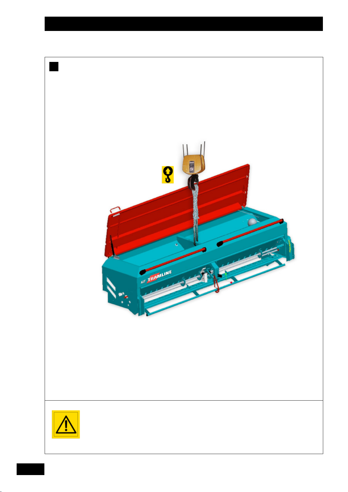
Ne lever le kit Tramline SE
qu’avec la trémie vide et
seul.
Assurez-vous qu’il n’y ait
personne autour de la
machine lors de la
manipulation.
The Tramline SE kit must
only be raised alone and
when the hopper is empty.
Make sure that there is
no-one around the
machine during handling
operations.
Tramline SE Satz nur
anheben, wenn nur ein
(leerer !) Tank angekoppelt
ist.
Sich vergewissern, daß
sich dabei niemand in
Nähe der Maschine
aufhält.
Page 15

Mise en route / Start-up / Inbetriebsetzung
A
Préparation de la machine
Manutention
B
FR
• Au moment de la livraison, vérifier que le semoir est
complet.
• Assurez-vous qu'il n'y ait pas de corps étrangers
dans la trémie.
• Le Kit Tramline SE ne doit être utilisé que pour les
travaux pour lesquels il a été conçu.
• Vérifier que la machine n’a subi aucun dommage en
cours de transport et qu’il ne manque aucune pièce.
Seules les réclamations formulées à réception de la
machine pourront être prises en considération.
• Faire constater d’éventuels dégâts par le
transporteur.
• En cas de doute ou de litige, adressez-vous à votre
revendeur.
A
Preparing the machine
• On delivery, check that the seed drill is complete.
• Ensure that there are no foreign bodies in the seed
box.
• The Kit Tramline SE should only be used for tasks
for which it has been designed.
• Utiliser l’anneau au centre prévu à cet effet.
• Manoeuvrer avec précaution afin d’éviter
d’endommager le couvercle.
Ne pas utiliser l’anneau pour lever l’ensemble
semoir plus outil de travail du sol.
Handling
B
• Use the centre ring provided for this purpose.
• Manœuvre carefully to avoid damaging the cover.
Do not use the ring to raise the combined
drill and cultivating implement.
1
1
GB
• Check that the machine has not suffered any
damage during transport and that no parts are
missing. Only claims made on taking delivery of the
machine will be considered.
• Any damage should be reported to the delivery
man.
• If in doubt or in the event of any complaint, please
contact your dealer.
Vorbereitung der Maschine
A
• Bei Lieferung prüfen, ob das Gerät komplett
geliefert wurde.
• Prüfen, ob sich kein Fremdkörper im Saatkasten
befindet.
• Die Kit Tramline SE nur für Arbeiten benutzen, für
die sie bestimmt ist.
• Prüfen, ob die Maschine nicht während des
Transports beschädigt worden ist und kein Teil fehlt.
Nur bei. Abnahme formulierte Reklamationen
können berücksichtigt werden.
Handhabung
B
• Zentralen, zu diesem Zweck vorgesehenen Ring
verwen den.
• Vorsichtig handhaben, um zu verhindern, den
Deckel zu beschädigen.
Ring nicht verwenden, um die Drillmaschine mit
samt Bodenbearbeitungsgerät vom Boden zu
heben.
DE
• Eventuelle Schäden vom Spediteur feststellen
lassen.
• Im Zweifelsfall Ihren Verkäufer informieren.
13
Page 16

Mise en route
C
P
M1
P2
P1
a b c d
M
M1mini
P
1c = M1 x (a + b) + P1 x b - M2 x (c + d)
2 x (c + d) - P1 x b + (0,2 x P x b)
=
a + b
b
M2
= .............. kg
= .............. kg
14
P
c = M1 + P + M2 = .............. kg
P
2c = Pc - P1c = .............. kg
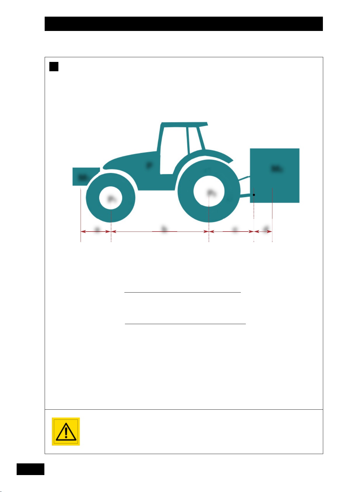
La charge sur l’essieu
avant du tracteur doit
être égal au moins à 20%
du poids à vide du
tracteur.
Page 17
Mise en route
C
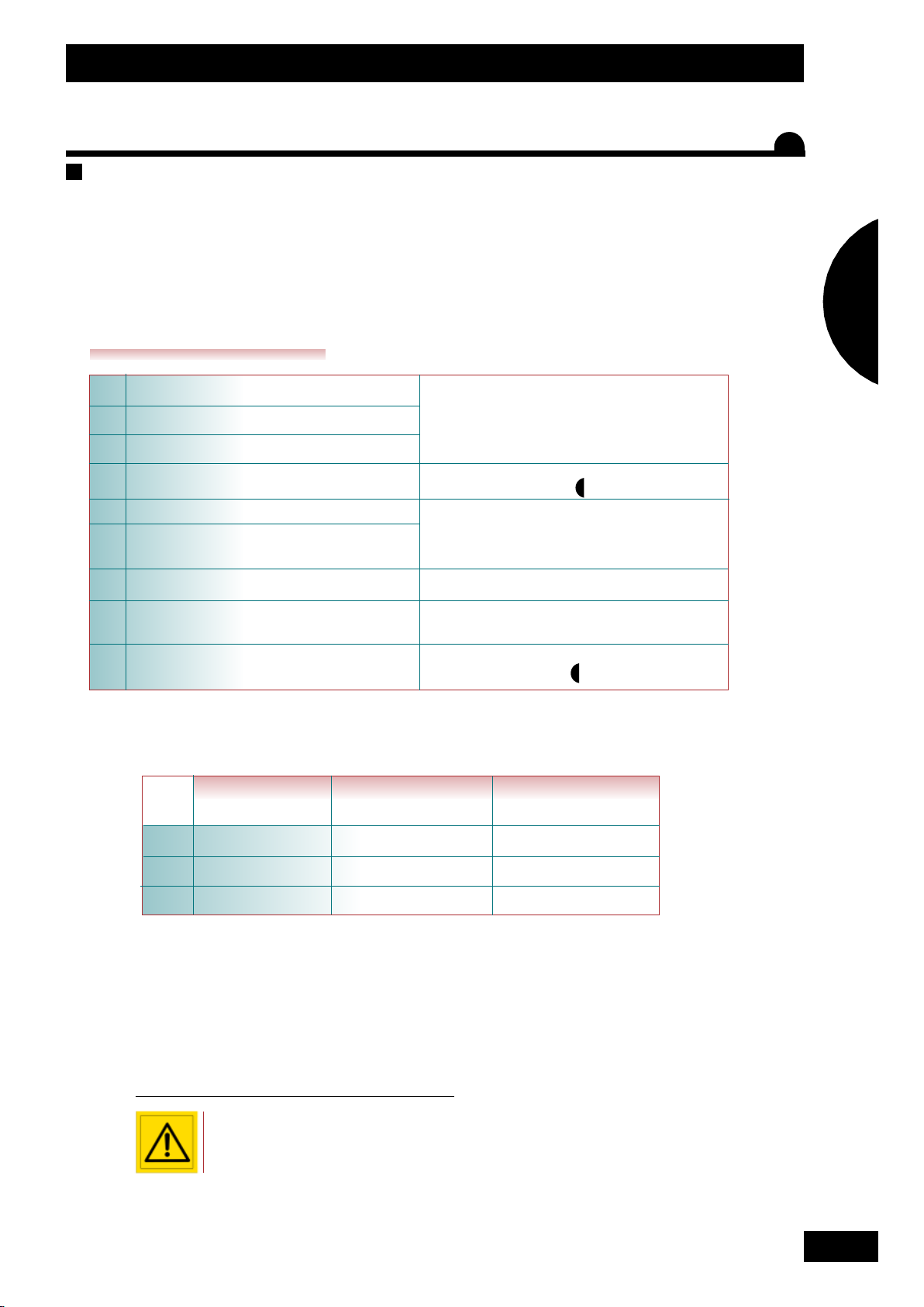
Contrôle tracteur
-
A vérifier :
• Le poids total autorisé.
• Les charges par essieu autorisées.
• La charge d’appui autorisée au point d’accouplement du tracteur.
• Les capacités de charge admissibles des pneumatiques montés sur le tracteur.
• La charge d’attelage autorisée est-elle suffisante ?
Toutes ces indications sont sur la carte grise, ou sur la plaque signalétique et dans la notice tracteur.
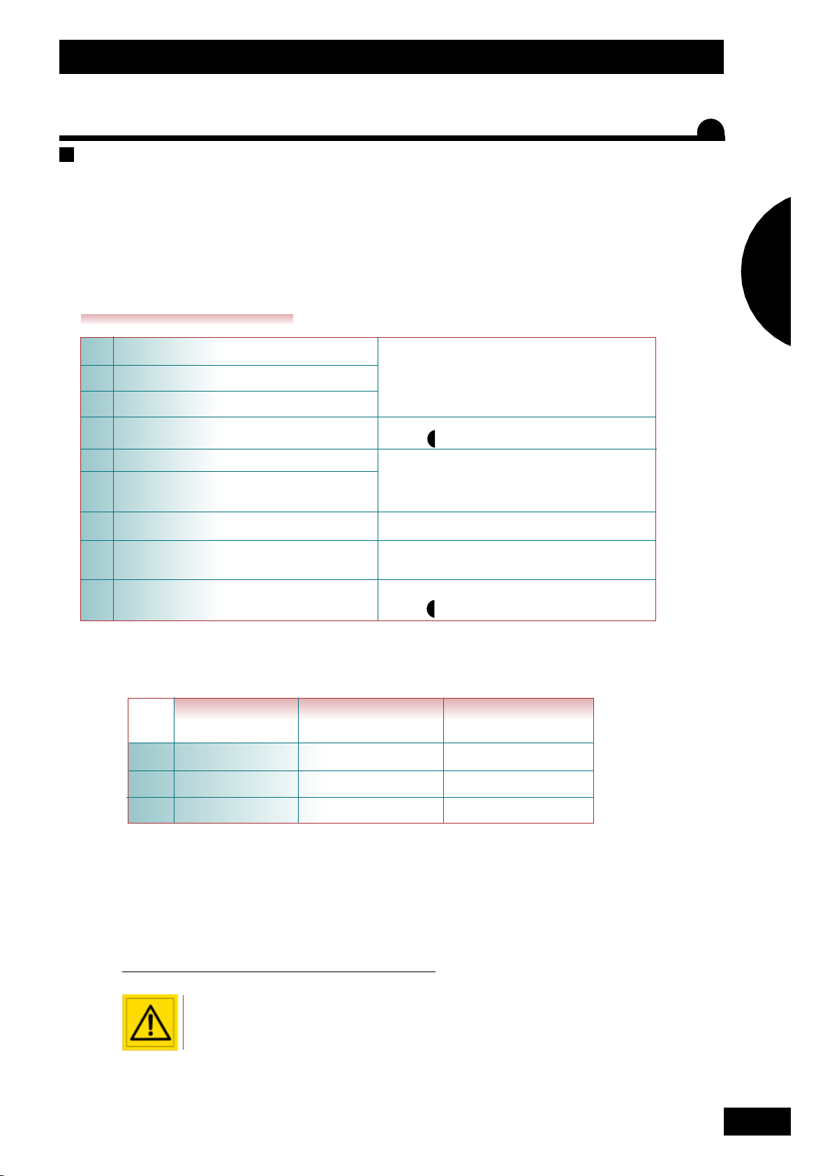
VALEURS À CONNAÎTRE
P (kg) Poids à vide du tracteur
P
1 (kg) Charge sur l’essieu avant du tracteur vide
P
2 (kg) Charge sur l’essieu arrière du tracteur vide
M
2 (kg) Poids total machine à l’arrière
M
1 (kg) Poids total du lest à l’avant
a (m) Distance entre le centre de gravité du lest
avant et le centre de l’essieu avant
b (m) Empattement du tracteur
c (m) Distance entre l’axe attelage inférieur et le
centre de l’essieu arrière
d (m) Distance entre l’axe attelage inférieur et le
centre de gravité de la machine
Consulter la notice d’utilisation ou la carte grise du
tracteur.
Consulter les caractéristiques techniques de la
machine. (voir chapitre “Caractéristiques).
Consulter les caractéristiques techniques du
tracteur et du lest avant, ou mesurer.
Consulter la notice d’utilisation ou la carte grise du
tracteur, ou mesurer.
Consulter la notice d’utilisation ou la carte grise du
tracteur, ou mesurer.
Consulter les caractéristiques techniques de la
machine. (voir chapitre “Caractéristiques).
3
3
FR
1
1
M1 mini = Calcul du lestage nécessaire à l’avant au minimum. P1c = Calcul de la charge sur l’essieu avant
P
c= Calcul du poids total de l’ensemble (tracteur +machine) P2c = Calcul de la charge sur l’essieu arrière
VALEURS VALEURS AUTORISÉES VALEURS AUTORISÉES
CALCULÉES PAR LE TRACTEUR PAR LES PNEUMATIQUES
P1c
P2c
Pc
- Complétez le tableau ci-dessus:
- Vérifiez que:
• Les valeurs calculées doivent être < ou = aux valeurs autorisées pour le tracteur et aussi par les pneumatiques
montés sur le tracteur.
• Il faut impérativement respecter sur l’essieu avant du tracteur une charge minimum > ou = à 20% de la
charge du tracteur à vide.
Il est interdit d’atteler la machine à un tracteur si:
MONTÉS SUR LE TRACTEUR
La charge totale calculée est > à la valeur autorisée.
La charge sur l’essieu avant est < au minimum requis.
15
Page 18

Start-up
C
P
M1
P2
P1
a b c d
M
M1mini
P
1c = M1 x (a + b) + P1 x b - M2 x (c + d)
P
c = M1 + P + M2 = .............. kg
2 x (c + d) - P1 x b + (0,2 x P x b)
=
a + b
b
M2
= .............. kg
= .............. kg
16
2c = Pc - P1c = .............. kg
P
The weight on the
tractor’s front axle should
be at least 20% of the
unladen weight of the
tractor.
Page 19

Start-up
C
Tractor control
-
To be checked: :
• The total authorised weight.
• The permitted weight per axle.
• The authorised support weight on the tractor’s linkage.
• The permissible load capacity for the tyres fitted to the tractor.
• Is the authorised linkage weight sufficient?
All of this information can be found on the registration papers, or on the data plate and in the tractor manual.
FIGURES THAT YOU SHOULD KNOW
P (kg) Unladen weight of tractor
P
1 (kg) Weight on the front axle when the tractor is empty
P
2 (kg) Weight on the rear axle when the tractor is empty
M
2 (kg) Total weight with machine attached to rear
M
1 (kg) Total weight of front ballast
a (m) Distance between the centre of gravity of the
front ballast and the centre of the front axle
b (m) Wheelbase of tractor
c (m) Distance between the lower linkage pins
and the centre of the rear axle.
Consult the tractor’s instruction manual or the
registration documents.
Consult the machine’s technical characteristics.
(see section “Characteristics”).
Consult the technical characteristics of the tractor
and the front ballast, or measure.
Consult the instruction manual or the tractor’s
registration documents, or measure.
Consult the instruction manual or the tractor’s
registration documents, or measure.
3
GB
1
1
d (m) Distance between the lower linkage pins
and the centre of gravity of the machine.
M1 mini = Calculation of the minimum ballast need in front. P1c = Calculation of the weight on the front axle
P
c= Calculation of the total weight of the unit (tractor + machine) P2c = Calculation of the weight on the rear axle
Consult the technical characteristics of the
machine. (see section “Charactéristics”).
3
VALUES TRACTOR’S VALUES PERMISSIBLE WITH
CALCULATED PERMISSIBLE VALUES THE TYRES THAT ARE
P1c
P2c
Pc
- Complete the table below:
- Check that:
• The values calculated should be < or = to the tractor’s permissible values and the values for the tyres fitted to
the tractor.
• It is essential that the minimum load on the front axle is > or = to 20% of the unladen tractor weight.
The machine must not be hitched to a tractor if:
FITTED TO THE TRACTOR
The total weight calculated is > than the maximum authorised weight.
The weight on the front axle is < than the minimum required.
17
Page 20
Inbetriebsetzung
C
P
M1
P2
P1
a b c d
M
M1mini
P
1c = M1 x (a + b) + P1 x b - M2 x (c + d)
2 x (c + d) - P1 x b + (0,2 x P x b)
=
a + b
b
M2
= .............. kg
= .............. kg
18
P
c = M1 + P + M2 = .............. kg
P
2c = Pc - P1c = .............. kg
Die vordere Achslast des
Schleppers muss
mindestes 20 % des
Schleppereigengewichts
betragen.
Page 21
Inbetriebsetzung
C
Schleppersteuerung
-
Bitte prüfen :
• Zulässiges Gesamtgewicht.
• Zulässige Achslast.
• Zulässiger Auflagedruck am Schlepperanbaupunkt.
• Zulässiges Ladegewicht der Schlepperreifen.
• Ist die zulässige Zuglast ausreichend?
Sämtliche dieser Angaben sind auf dem Fahrzeugschein oder auf dem Typenschild und im Schlepperhandbuch vermerkt.
WICHTIGE WERTE
P (kg) Schleppereigengewicht
P
1 (kg) Vordere Achslast bei leerem Schlepper
P
2 (kg) Hintere Achslast bei leerem Schlepper
M
2 (kg) Gesamtgewicht Maschine hinten
M
1 (kg) Ballastgewicht vorne
a (m) Abstand zwischen Ballastschwerpunkt
vorne und Achsmittelpunkt vorne
b (m) Radabstand Schlepper
c (m) Abstand zwischen unterer Ankupplungsachse
und dem Achsmittelpunkt hinten
Siehe Handbuch oder Fahrzeugschein des
Schleppers.
Technische Daten der Maschine einsehen. (siehe
Kapitel “Technische Daten”).
Technische Daten des vorne ballastierten
Schleppers einsehen oder messen.
Siehe Handbuch oder Fahrzeugschein des
Schleppers oder messen.
Siehe Handbuch oder Fahrzeugschein des
Schleppers oder messen.
3
DE
1
1
d(m)Abstand zwischen unterer Ankupplungsachse
und dem Schwerpunkt der Maschine
M1 mini = Berechnung des erforderlichen Mindestballasts vorne. P1c = Berechnung der Vorderachslast
P
c= Berechnung der Gesamtlast (Schlepper +Maschine) P2c = Berechnung der Hinterachslast
Technische Daten der Maschine einsehen. (sieh
Kapitel “Technische Daten”).
3
BERECHNETE FÜR DEN SCHLEPPER FÜR DIE SCHLEPPERREIFEN
WERTE ZULÄSSIGE WERTE ZULÄSSIGE WERTE
P1c
P2c
Pc
- Untenstehende Tabelle ausfüllen:
- Überprüfen Sie Folgendes:
• Die berechneten Werte müssen < oder = der für den Schlepper bzw. für die Schlepperreifen zulässigen Werte
sein
• Die Vorderachse muss unbedingt mit > oder = 20 % des Schleppereigengewichts ballastiert sein.
Maschine nicht an den Schlepper ankuppeln, solange:
Die berechnete Gesamtlast > als der zulässige Wert ist.
Der Ballast auf der Vorderachse < als der erforderliche Mindestballast ist.
19
Page 22
Mise en route / Start-up / Inbetriebsetzung
D
2
2
2
2
1
1
E
40°
3
3
Avant la mise en service
de l’ensemble
outil/semoir, assurezvous avec votre
revendeur de la
conformité avec la
réglementation en
matière de sécurité du
travail et avec les
dispositions du code de
la route.
Contact your dealer
before using the
implement/drill
combination to make
sure that work safety
regulations and the
Highway Code are not
being contravened.
Versichern Sie sich vor
der Inbetriebnahme der
Drillmaschine mit
Bodenbearbeitungsgerät
gegenüber Ihrem
Fachhändler, dass die
Vorschriften zur
Arbeitssicherheit und der
Straßenverkehrsordnung
eingehalten werden.
20
Page 23

Mise en route / Start-up / Inbetriebsetzung
D
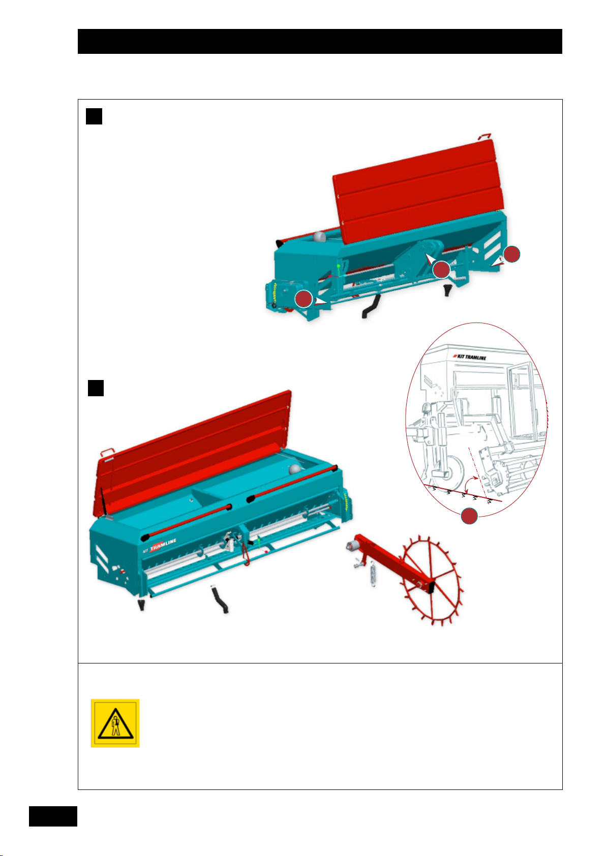
Montage de la trémie
Montage des tuyaux de transport
E
FR
• Le montage de la trémie est à réaliser par votre
revendeur.
• Poser la trémie sur la partie AR de l’outil, respecter
le parallélisme des flasques , les points et
sont à rendre solidaire sur le chassis porteur,
respecter l’aplomb de la trémie.
Remarque
Il est obligatoire de réaliser une plate-forme et
marches
d’accès à la trémie pour le chargement, si elle est à
une hauteur et profondeur trop importante.
Attention
L'adaptation de la trémie avec un outil de travail du sol
doit être conforme aux directives CE en vigueur.
Les travaux de mise en conformité doivent être
réalisés par votre revendeur si ils sont nécessaires.
Attaching the hopper
D
• Your dealer must attach the hopper to the imple
ment.
• Place the hopper on the rear of the implement.
Ensure that the side plates are parallel. Points
and must be firmly fixed to the supporting
frame. Make sure that the hopper is correctly
aligned.
- Placer les tuyaux à égale distance sur la largeur de
travail de l’outil.
- Eviter les coudes et les angles trop prononcés.
- Ne pas dépasser un angle de 40° pour avoir un
bon écoulement de la semence.
- Ne pas mettre les tuyaux dans le flux de terre.
Fitting the delivery hoses
E
- Fit the hoses an equal distance apart across the
implement’s working width.
- Avoid any dogleg bends or sharp corners in the
hose.
- To allow the seed to flow smoothly keep the angle
of the hose at 40° or less.
- Do not place the hoses in the ground flow.
1
1
GB
Note:
The hopper must include an access deck and steps
for loading if the hopper is too high and deep.
Warning:
Current EC directives must be observed when fitting
a cultivating implement to the hopper.
Your dealer must carry out work required to bring
the equipment into compliance.
Tankanbau.
D
• Der Anbau des Tanks an das
Bodenbearbeitungsgerät ist durch den Fachhändler
durchzuführen.
• Tank auf den hinteren Teil des
Bodenbearbeitungsgeräts absetzen, auf die
Parallelität der Flansche achten.
Die Punkte und müssen mit dem tragenden
Fahrgestell verschraubt werden, dabei auf die
Senkrechtposition des Tanks achten.
Anmerkung
Für den Tank sind zum Besteigen unbedingt
Treppenstufen und eine Laufplattform anzulegen,
wenn der Tank hoch liegt und sehr tief ist.
Achtung
Die Anpassung des Tanks an ein
Bodenbearbeitungsgerät muss den geltenden EU
Vorschriften entsprechen.
Wenn Anpassungsarbeiten an die Vorschriften
erforderlich sind, müssen diese durch Ihren
Fachhändler durchgeführt werden.
E
Anbau der Beförderungsrohre
- Beförderungsrohre beidseits in gleichem Abstand
zur Arbeitsbreite des Geräts platzieren.
- Zu enge Winkel und Knicke vermeiden.
- Winkelenge von 40° nicht überschreiten, so dass
das Saatgut regelmäßig auslaufen kann.
- Beförderungsrohre nicht in die Erdbewegung legen.
DE
21
Page 24
Mise en route / Start-up / Inbetriebsetzung
F
80
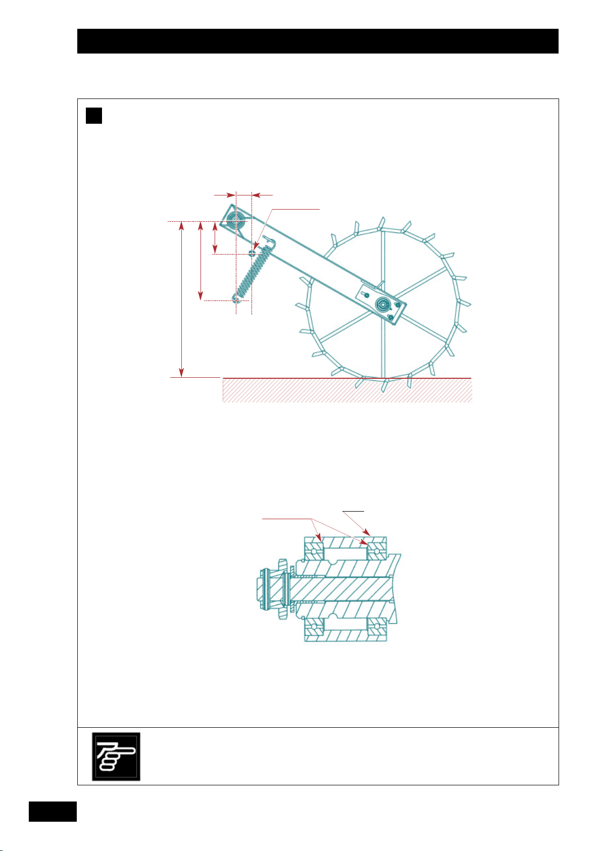
Butée basse
164
396
787
Bien respecter les
consignes de
positionnement du bras
de roue.
Roulements
Follow the instructions
carefully when
positioning the wheel
arm.
Palier
Positionierungsanleitung
des Radarms genau
beachten.
22
Page 25

Mise en route / Start-up / Inbetriebsetzung
F
Montage du bras de roue
- Souder le palier de bras de roue, roulements
démontés et hors de leur portée.
- Il est obligatoire de protéger par un carter la chaîne
(pas 12,7) reliant le bras de roue au variateur.
Remarque
Si vous réalisez votre propre transmission, vous devez
obtenir 60 tours d’arbre d’entrée de variateur sur une
distance de 100 m.
FR
1
1
GB
Fitting the wheel arm
F
- Weld the wheel-arm bearing support, with the roll
bearings removed and out of the bearing surface.
- The chain (12.7 pitch) connecting the wheel arm to
the variator must be protected with a chain guard.
Note
If you are using your own transmission shaft, the
variator input shaft needs to rotate 60 times over 100
metres.
Anbau des Radarms
F
- Radarmlager schweißen, wenn die Kugellager
abgebaut
und außer Reichweite sind.
- Kette (Kettengang 12,7) unbedingt durch ein
Gehäuse
schützen, das den Radarm mit dem Regler
verbindet.
DE
Anmerkung
Wenn Sie Ihre eigene Gelenkwelle anbauen, brauchen
Sie 60 U/min an der Antriebswelle des Reglers über
einen Abstand von 100 m.
23
Page 26

Mise en route / Start-up / Inbetriebsetzung
G
3
1
1
2
2
2
2
3
1
1
3
3
24
Page 27

Mise en route / Start-up / Inbetriebsetzung
FR
G
Montage de la trémie sur Discomix
• Le montage de la trémie est à réaliser par votre
revendeur.
• Réaliser le perçage suivant le schéma.
• Poser la trémie sur la partie AR de l’outil, respecter
le parallélisme des flasques, les points , et
sont à rendre solidaire sur le chassis porteur,
respecter l’aplomb de la trémie.
Montage du bras de roue à faire sur la pièce .
Remarque
Il est obligatoire de réaliser une plate-forme et des
marches
d’accès à la trémie pour le chargement, si elle est à
une hauteur et profondeur trop importante.
Attention
L'adaptation de la trémie avec un outil de travail du sol
Fitting the hopper to the Discomix
G
• Your dealer must attach the hopper to the imple
ment.
• Place the hopper on the rear of the implement.
Ensure that the side plates are parallel. Points
, and must be firmly fixed to the supporting
frame. Make sure that the hopper is correctly
aligned.
doit être conforme aux directives CE en vigueur.
Les travaux de mise en conformité doivent être
réalisés par votre revendeur si ils sont nécessaires.
H
Montage des tuyaux de transport
- Placer les tuyaux à égale distance sur la largeur de
travail de l’outil.
- Eviter les coudes et les angles trop prononcés.
- Ne pas dépasser un angle de 40° pour avoir un
bon écoulement de la semence.
- Ne pas mettre les tuyaux dans le flux de terre.
Fitting the delivery hoses
H
- Fit the hoses an equal distance apart across the
implement’s working width.
- Avoid any dogleg bends or sharp corners in the
hose.
- To allow the seed to flow smoothly keep the angle
of the hose at 40° or less.
- Do not place the hoses in the ground flow.
1
1
GB
The wheel arm should be fitted to part .
Note:
A platform and steps must be fitted
The hopper must include an access deck and steps for
loading if the hopper is too high and deep.
Warning:
Current EC directives must be observed when fitting a
cultivating implement to the hopper.
Your dealer must carry out work required to bring the
equipment into compliance.
Montage des Trichters auf dem Discomix
G
• Der Anbau des Tanks an das
Bodenbearbeitungsgerät ist durch den Fachhändler
durchzuführen.
• Tank auf den hinteren Teil des
Bodenbearbeitungsgeräts absetzen, auf die
Parallelität der Flansche achten.
Die Punkte , und müssen mit dem tragenden
Fahrgestell verschraubt werden, dabei auf die
Senkrechtposition des Tanks achten.
Die Montage des Radararmes auf dem Teil muss
gemacht werden.
Anmerkung
Es ist unbedingt erforderlich, eine Plattform und
Stufen zu realisieren
Für den Tank sind zum Besteigen unbedingt
Treppenstufen und eine Laufplattform anzulegen,
wenn der Tank hoch liegt und sehr tief ist.
Achtung
Die Anpassung des Tanks an ein
Bodenbearbeitungsgerät muss den geltenden EU
Vorschriften entsprechen.
Wenn Anpassungsarbeiten an die Vorschriften
erforderlich sind, müssen diese durch Ihren
Fachhändler durchgeführt werden.
Anbau der Beförderungsrohre
H
- Beförderungsrohre beidseits in gleichem Abstand
zur Arbeitsbreite des Geräts platzieren.
- Zu enge Winkel und Knicke vermeiden.
- Winkelenge von 40° nicht überschreiten, so dass
das Saatgut regelmäßig auslaufen kann.
- Beförderungsrohre nicht in die Erdbewegung legen.
DE
25
Page 28

Réglages / Settings / Einstellungen
A
1)
2)
0
1
2
1
1
2
2
26
Suivre les indications de
réglage.
3
3
Follow the setting
indications.
Einstellanweisungen
befolgen.
Page 29

Réglages / Settings / Einstellungen
FR
A
Réglage du débit
a) Réglage de la distribution
(voir chapitre 4 pour les valeurs de réglage)
1) Trappe de distribution
• Lever ou baisser la trappe en fonction des
recommandations. Encliqueter le ressort dans
l’encoche correspondante.
• La trappe dispose de 3 positions
• Repère 0 . Fermé
(semi 1 rang sur 2 par exemple)
1 . Petites graines < 8 kg/ha
2 . Grosses graines
Setting the flow
A
a) Setting the distribution
(see section 4 for the setting values)
1) Distribution shutter
• Raise or lower the shutter as recommended.
Insert the spring into the corresponding catch.
• into the corresponding catch.
• Setting 0 . Closed
(sowing one row in two, for instance)
1 . Small grain < 8 kg/ha
2 . Large grain.
2) Clapet de fond
• Déplacer légèrement le levier sur la droite et
mettre au cran correspondant.
• Repère 1 . Céréales
2 . Céréales de gros diamètre
3 .
4 . Pois de conserve
5 . Pois
6 . Féverole
Maxi . Position basse, Vidange
• Il faut rechercher à accompagner la graine avec
l'ergot en resserrant le plus possible le clapet de fond
(ex: repère 1 pour blé, orge).
Toutefois, si vous observez des projections de graines
de la distribution en permanence, placer le levier au
cran supérieur par rapport à la préconisation
(ex: repère 2 pour blé, orge).
2) Baffle plate
• Move lever slightly to the right and set to the
appropriate mark.
• Setting 1 . Cereal
2 . Large cereal
3 .
4 . Canning peas
5 . Peas
6 . Field beans
Max . Bottom position, Emptying
• The aim is to have the grain metered out by the
feeding roller by keeping the baffle plate as tightly
closed as possible
(e.g. setting 1 for wheat and barley).
However, if you notice a constant projection of grain
from the distribution system, set the lever one mark
higher than the recommendation
(e.g. setting 2 for wheat and barley).
1
GB
2
DE
Einstellung der Saatmenge
A
a) Einstellung der Verteilung
(vgl. Kapitel 4 bezüglich der Einstellwerte)
1) Auslaufschieber
• Schieber gemäß Empfehlungen heben oder
senken. Feder in die entsprechende Nut
einklinken.
• Der Schieber hat 3 Stellungen.
• Markierung 0 . Geschlossen
(z.B. Aussaat alle 2 Reihen)
1 . Kleine Körner < 8 kg/ha
2 . Großkorn-Dibbelklappe.
2) Bodenklappe
• Hebel leicht nach rechts verschieben und in die
entsprechende Kerbe einrasten.
• Markierung 1 . Getreide
2 . Getreide mit großem Durchmesser
3 .
4 . Erbsen für Konserven
5 . Erbsen
6 . Pferdebohnen
Maxi . Untere Stellung, Entleerung
• Ziel ist, das Korn mit dem Nockenrad zu führen,
indem die Bodenklappe so stark wie möglich
angezogen wird
(B. : Markierung 1 für Weizen, Gerste).
Sollten jedoch ständig Körner aus der Verteilung
spritzen, Hebel eine Kerbe höher stellen als
empfohlen (B. : Markierung 2 für Weizen, Gerste).
27
Page 30

Réglages / Settings / Einstellungen
A
3)
a
a
b
b
2
2
1
1
4)
4
4
5
5
3
3
28
Suivre les indications de
réglage.
Follow the setting
indications.
Einstellanweisungen
befolgen.
Page 31

Réglages / Settings / Einstellungen
FR
3) Sélection de l'ergot
Roue standard pour céréales et grosses graines.
Roue fine pour petites graines.
• Prendre la goupille sur la trappe du 1er boîtier à
droite.
- Pour sélectionner la roue de distribution:
a . Appuyer
b . Tourner
3) Selecting the feeding roller
Standard wheel for cereal and large grain.
Fine wheel for small grain.
• Take hold of the pin on the shutter of the first unit
to the right.
- Take hold of the pin on the shutter of the first
unit to the right.
a . Press
b . Turn
4) Variateur
• Mettre le repère déterminé à l’essai de débit à l’aide
de la molette , et du levier .
• La lecture se fait au dessus de la partie plane .
• Chaque changement de repère doit être suivi d’un
contrôle de débit. Pour information, 3 graduations
de vernier correspondent à un écart d’environ 10
Kg/ha avec des céréales.
• Repère de 0 à 90.
4) Variator
• Using the knob , and lever , set to the mark
determined during the calibration test.
• Read off above the flat part .
• Each change to the setting must be followed by a
calibration check. For your information, three
graduations on the adjustment scale correspond
to a deviation of around 10 kg/ha with cereal.
• Scale from 0 to 90.
1
GB
2
3) Wahl des Nockenrads
Normalrad für Getreide und dicke Körner.
Feines Särad für kleine Körner.
• Den Splint auf dem Schieber des 1. Gehäuses
rechts nehmen.
- Zur Wahl des Särades:
a . Drücken
b . Drehen
DE
4) Getriebe
• Bei der Abdrehprobe festgelegte Markierung mit
der Rändelschraube und dem Hebel
einstellen.
• Die Ablesung erfolgt an der Oberfläche des
Hebels .
• Jeder Markierungsänderung muß eine
Abdrehkontrolle folgen. Zur Information: 3
Gradeinteilungen der Fein einstellvorrichtung
entsprechen einer Abweichung von ca. 10 kg/ha
bei Getreide.
• Markierung von 0 bis 90.
29
Page 32

Réglages / Settings / Einstellungen
A
1
1
4
4
2
2
3
3
Pour un semis très précis,
il est nécessaire de
réaliser un essai de débit.
Attention à la précision
de votre balance.
A calibration test is
necessary for accurate
sowing.
Make sure that your
scales are accurate.
2
2
Für eine sehr präzise Saat
ist eine Abdrehprobe
erforderlich.
Die Waage muß genau
sein.
30
Page 33

Réglages / Settings / Einstellungen
b) Mise en place de l’essai de débit
FR
• Procurez-vous une balance précise et un récipient.
• Avant d’effectuer votre essai, vérifier qu’il n’y a
personne près du semoir.
• Démarche
a . Retirer les augets .
b . Déverrouiller la barre à godet et la
baisser.
c . Mettre les augets sous les distributions .
d . Prendre la manivelle de terrage et
l'engager sur l'arbre du variateur.
• Vérifier que les distributions utilisées soient
enclenchées.
• Effectuer votre essai de débit suivant les
recommandations des pages suivantes.
b) Setting up the calibration test
• Use accurate scales and a container.
• Before carrying out the test, check that there is noone around the seed drill.
• Procedure:
a . Remove the trays .
b . Unlock the bucket bar and lower it.
c . Put the trays under the metering devices .
d . Fit the depth control crank on to the
variator shaft.
• Pour vider plus facilement la semence de l'auget,
utiliser la trappe.
• Remettre l’auget en position carter.
1
GB
2
• Use the shutter to empty the seed tray more easily.
• Bring the tray back to the guard position.
• Check that the metering devices used are engaged.
• Carry out the calibration check in line with the
recommendations on the following pages.
b) Einrichten des Abdrehproben-Sets
• Besorgen Sie sich eine Präzisionswaage und einen
Behälter.
• Sich vor Durchführung der Abdrehprobe
vergewissern, daß sich niemand in Nähe der
Drillmaschine aufhält.
• Vorgangsweise
a. Kippwannen abnehmen.
b. Kübelstange entriegeln und absenken.
c. Kippwannen unter die Saatgutverteiler
platzieren.
d. Die Schardruckverstellkurbel auf die
Getriebewelle stecken.
•
Kontrollieren, ob die Verteilungen in Gang gebracht
sind.
• Mit Hilfe des Schiebers lässt sich das Saatgut
leichter aus der Kippwanne entleeren.
•
Mulde wieder in die Position als Abdeckschutz
bringen.
DE
• Die Abdrehprobe gemäß den Empfehlungen auf
den folgenden Seiten durchführen.
31
Page 34

Réglages / Settings / Einstellungen
B
É
1
5
21
1 tr / s
m 2,50 3,00 4,00
tr 60 50 37,5
6 7
3
1
2
3
2
4
ou - or - oder
x 40 = Kg / ha
8
Mini 5 Kg
Mini 150 Kg
3
LLÉ
W
EAT
W
EIZEN
12 12,5 13 13,6 14 14,3 15 15,7 16 16,7
60
19 20 20 21 22 22 23 25 25 26
70
22 23 24 25 26 26 27 29 29 31
80
25 26 27 29 29 30 32 33 34 35
90
28 30 31 32 33 34 35 37 38 39
100
32 33 34 36 37 38 39 41 42 44
110
35 36 38 39 40 41 43 45 46 48
120
38 39 41 43 44 45 47 49 50 52
130
41 43 44 46 47 48 51 53 54 56
140
44 46 47 49 51 52 54 56 57 59
150
47 49 51 53 54 55 57 60 60 63
160
50 52 54 56 57 58 60 63 64 66
170
53 55 56 59 60 61 63 66 67 69
180
55 57 59 61 63 64 66 69 70 72
190
58 60 62 64 66 67 69 72 72 75
200
60 62 64 67 68 69 72 74 75 78
210
63 65 67 69 71 72 74 77 78 80
220
65 67 69 72 73 74 77 79 81 83
230
67 70 72 74 76 77 79 82 83
240
70 72 74 76 78 79 82 85
250
72 74 76 79 80 81 84
260
74 76 78 81 83 84
270
76 78 80 83 85
280
78 80 83
290
80 82 85
300
82 84
4
9
ha = 0
10
Mini 100 tr
Mini 25 tr
5 6 7
+
+
32
Page 35

Réglages / Settings / Einstellungen
c) Réalisation de l’essai de débit
1) Essai en poste fixe
FR
Procéder au réglage de la distribution comme
1
l’indique la notice (clapet de fond, trappes
etc...).
Mettre la graine dans la trémie le jour
2
même du semis (5 Kg en colza / 150 Kg en
céréales) et réaliser l’essai à suivre.
Régler le variateur suivant le repère indicatif
3
du tableau (voir chapitre 5).
Amorcer la distribution : 25 tours de
4
manivelle minimum (l’auget peut être
rempli), sauf pour le colza 100 tours.
Faire l’essai en effectuant le nombre de
5
tours en fonction de la largeur du semoir.
Nota : tourner régulièrement
à 1 tour/seconde.
c) Carrying out the calibration test
1) Fixed unit test
Set the distribution as indicated in the manual
1
(baffle plate, shutters, etc.).
Put the grain in the seed box
2
wing (5 kg of rape, 150 kg of cereal) and
so
carry out the following test.
Set the variator to the mark indicated in the
3
table (see section 5).
Start distribution: a minimum of 25 turns
4
of the crank (the trough may be filled), or
100 turns for rape.
Carry out the test by completing the
5
appropriate number of turns for the width of
the seed drill.
N.B. Turn steadily at 1 turn per second.
on the day of
Peser la quantité recueillie dans les augets avec
6
une balance précise.
Multiplier par 40 pour obtenir la quantité par ha
7
ou utiliser la réglette (voir page suivante).
Corriger le réglage du variateur (baisser
8
complètement le levier pour le ramener ensuite à la
valeur souhaitée).
Ramener le compteur d’hectares à zéro, après
9
l’essai de débit.
L’essai en condition réelle est le plus
10
représentatif.
Après un hectare de semis, refaire un essai de
vérification (procéder comme ci-dessus à partir
de ).
5
Weigh the quantity collected in the trays with an
6
accurate set of scales.
Multiply by 40 to obtain the quantity per hectare
7
or use the calculator (see next page).
Correct the variator setting (lower the lever
8
completely then bring it back up to the required
value).
Reset the area meter to zero after the calibration
9
test.
The most representative test is one carried
10
out under real working conditions.
After sowing a hectare, carry out a further
check (proceed as above from step ).
1
GB
2
5
c) Durchführung der Abdrehprobe
1) Probe im Stillstand
Einstellung der Verteilung gemäß Anweisung
1
vornehmen (Bodenklappe, Schieber, usw..).
Das Korn am Tag der Aussaat in den
2
Saatkasten geben (5 kg bei Raps/ 150 kg bei
Getreide) und die notwendige Probe
durchführen.
Das Getriebe gemäß der in der Tabelle
3
angegebenen Markierung einstellen (vgl.
Kapitel 5).
Die Verteilung in Gang bringen: mindestens
4
25 Kurbelumdrehungen (die Mulde kann
gefüllt werden), aber 100 Umdrehungen
für Raps.
Probe vornehmen, indem eine der
5
5
5
Drillmaschinenbreite entsprechende Anzahl
von Umdrehungen vorgenommen wird.
Anmerkung: regelmäßig eine Umdrehung/
Sekunde vornehmen.
In den Mulden aufgefangene Menge mit einer
6
Präzisionswaage wiegen.
Mit 40 multiplizieren, um die Menge pro ha zu
7
erhalten oder Einstellscheibe benutzen (s.
nächste Seite).
Die Getriebe-Einstellung korrigieren (den Hebel
8
völlig senken und dann wieder auf den
gewünschten Wert stellen).
Den Hektarzähler nach der Abdrehprobe wieder
9
auf Null stellen.
Eine Probe unter reellen Bedingungen ist die
10
beste. Nach einem Hektar Aussaat eine Probe
zur Kontrolle durchführen (wie o.a. ab Punkt
).
5
DE
33
Page 36

Réglages / Settings / Einstellungen
A
4
4
1
1
34
2
3
3
2
Page 37

Réglages / Settings / Einstellungen
2) Essai avec la réglette
FR
• Cette réglette vous permet de déterminer le
nouveau repère de variateur après votre 1er essai
de débit.
• Effectuer les réglages de la distribution et un essai
suivant les recommandations données dans les
pages précédentes.
• Utilisation :
- Faire coïncider la ligne du repère du
variateur qui a servi à votre 1er essai de
débit avec la ligne qui correspond à la
quantité recueillie à cet essai dans l’auget
en Kg.
- Sans bouger les disques de la réglette,
repérer sur la ligne votre débit souhaité
sur la ligne Kg/ha.
2) Testing with the calculator
• This calculator enables you to determine the new
variator setting after your first calibration test.
• Set the distribution and carry out a test in line with
the recommendations given on the previous
pages.
• Use:
- Match line , the variator setting used for
your first calibration test, up to line which
corresponds to the quantity collected in the
trough in kg during this test.
- Lire sur la ligne le nouveau repère de
variateur correspondant à votre semence
suivant vos conditions.
• Après un hectare de semis, refaire un essai de
vérification
• Si vous désirez changer le débit/ha avec la même
semence sur une autre parcelle, vous pouvez
réutiliser la réglette pour déterminer le nouveau
repère du variateur en gardant la valeur de pesée
du 1er essai de débit.
1
GB
2
- On line , read off the new variator setting
corresponding to your seed and conditions.
• After sowing a hectare, carry out a further check.
• If you wish to change the seeding rate per hectare
with the same seed on another plot, you can use
the calculator again to determine the new variator
setting by keeping the weighed quantity obtained
in the first calibration test.
- Without moving the discs on the calculator,
identify your required seeding rate in kg/ha
on line .
2) Probe mit der Einstellscheibe
• Diese Einstellscheibe erlaubt Ihnen, die neue
Getriebe-Markierung nach der 1. Abdrehprobe
zu bestimmen.
• Die Einstellungen der Verteilung und eine Probe
gemäß den Empfehlungen auf den vorherigen
Seiten durch führen.
• Benutzung:
- Die Linie der Getriebe-Markierung, die
für die 1. Abdrehprobe gedient hat, mit
der Linie in Übereinstimmung bringen,
die der bei dieser Probe in der Mulde
aufgefangenen Menge in kg entspricht.
- Ohne Verschiebung der Einstellscheibe
auf der Linie Ihre gewünschte
Streumenge auf der Linie kg/ha suchen.
DE
- Auf der Linie die neue GetriebeMarkierung ablesen, die Ihrem Saatgut
gemäß Ihren Bedingungen entspricht.
• Nach einem Hektar Aussaat eine neue Probe
zur Kontrolle durchführen.
• Wollen Sie die Streumenge/ha mit dem gleichen
Saatgut auf einer anderen Parzelle ändern,
können Sie erneut die Einstellscheibe
verwenden, um die neue Getriebe-Markierung
unter Beibehaltung des gewogenen Wertes der
1. Abdrehprobe zu ermitteln.
35
Page 38

Réglages / Settings / Einstellungen
C
2
2
1
1
B
b
a
b
a
36
Il est impératif de vider la
trémie après le travail,
pour éviter les dégâts
causés par les rongeurs.
It is essential to empty
the seed box after sowing
to avoid rodent damage.
Saatkasten nach Einsatz
zum Schutz vor
Nagetieren unbedingt
völlig entleeren.
Page 39

Réglages / Settings / Einstellungen
B
Débrayage demi-semoir
Vidange de la trémie
C
FR
• Le désaccouplement de la noix centrale entre les
1/2 arbres de distribution est possible pour
correspondre au passage de jalonnage. Seul le côté
gauche est débrayable.
• Pour débrayer
- a - Pousser
- b - Tourner
Disengaging half of the seed drill
B
• The centre sleeve between the distribution halfshafts may be uncoupled to match up with the
tramlining. Only the left-hand side may be
disengaged.
• To disengage:
- a - Push
- b - Twist
• La vidange de la trémie se fait dans l'auget .
• Positionner l'auget sous la distribution et abaisser le
levier à fond vers le bas.
• Pour stopper l'écoulement de la graine alors que la
trémie n'est que partiellement vide, lever légèrement
le levier sans chercher à le mettre en position haute.
Emptying the seed box
C
• The seed box is emptied into the tray .
• Position the tray beneath the metering devices and
push the lever fully down.
• To stop the grain flow when the seed box is only
partly empty, lift the lever very slightly.
1
GB
2
Abschalten 1/2 Drillmaschine
B
• Die Zentralnuß zwischen den Halbwellen der
Verteilung kann entkuppelt werden, um dem
Fahrgassendurchgang zu entsprechen. Nur die linke
Seite kann ausgekuppelt werden.
• Zum Auskuppeln
- a - Schieben
- b - Drehen
Entleeren des Saatkastens
C
• Der Saatkasten wird in die Mulde entleert.
• Die Mulde unter der Verteilung anbringen und den
Hebel ganz nach unten drücken.
• Zum Stoppen des Kornflusses bei nur teilweise
entleertem Kasten den Hebel leicht anheben, ohne
zu versuchen, ihn nach oben zu stellen.
DE
37
Page 40

Entretien / Maintenance / Wartung
38
Bien respecter les
périodicités de vidange
du variateur.
Ne jamais graisser les
distributions et les tubes
de descente.
Change the variator oil
according to the
recommended frequency.
Never grease the
metering devices or the
coulter tubes.
Die Ölwechselabstände
für das Ölbadgetriebe
einhalten.
Niemals die Saatausläufe
und Saatrohre schmieren.
Page 41

Entretien / Maintenance / Wartung
A
Entretien
Vérification
C
FR
• Souffler intérieur trémie
• Laver le semoir sans haute pression
• Pour le nettoyage et entretien, porter
lunette de protection et gants pour
éviter toutes blessures.
• Si il reste de la semence porter un
masque anti-poussière pour éviter toute
inhalation.
B
Graissage
• Huiler la chaîne de distribution.
• Vérifier le niveau d'huile du variateur (semoir
horizontal), ajuster le niveau au point rouge avec de
l'huile de boîte de vitesses automatiques. ATF DEXTRON II D
Effectuer la vidange tous les 500 ha ou tous les
2 ans si la surface n'est pas effectuée.
• Graisser le palier de la roue DPA.
Maintenance
A
• Clean inside the seed box with a blower.
• Wash the seed drill without using high pressure.
• For cleaning and maintenance, wear
protective glasses and gloves to prevent
injury.
• If there is left-over seed, wear a dust
mask to prevent inhaling dust.
• Vérifier régulièrement le serrage de l’ensemble des
boulons.
• Il est important d’effectuer un resserrage de tous
les boulons après les premières heures de travail.
Checks
C
• Check regularly that all the bolts are still tight.
• Every bolt must be re-tightened after the first few
hours of use.
GB
B
Lubrication
• Lubricate the drive chain.
• Check the oil level in the variator (with drill
horizontal) and top up to the red dot with ATF DEXTRON II D automatic gearbox oil.
Change the oil every 500 hectares, or every 2 years
at the most.
• Lubricate the DPA wheel bearing.
Wartung
A
• Saatkasten innen sauberblasen.
• Drillmaschine ohne Hochdruck waschen
• Zur Vermeidung von Verletzungen beim
Reinigen und bei der Instandhaltung
Schutzbrille und Handschuhe tragen.
• Sind Saatgutrückstande vorhanden, eine
Staub-schutz maske tragen.
Schmierung
B
• Antriebskette ölen.
• Ölstand des Getriebes kontrollieren (Drillmaschine
waagerecht), bis zum roten Punkt mit Öl für
automatische Getriebe (ATF -DEXTRON II D)
ergänzen.
Ölwechsel alle 500 ha oder alle 2 Jahre, wenn diese
Fläche nicht erreicht wird.
• Lager des DPA-Rads schmieren.
Prüfung
C
• Regelmäßig prüfen, ob alle Schrauben an der
Maschine fest angezogen sind.
• Nach den ersten Arbeitsstunden sollten alle
Schrauben nochmals angezogen werden.
1
3
DE
39
Page 42

Entretien / Maintenance / Wartung
6 mm
D
1
1
1
1
3
3
2
2
4
4
40
Page 43

Entretien / Maintenance / Wartung
D
Distribution
FR
• Ne jamais laisser de la semence dans la trémie
pendant une longue période.
• Ouvrir les trappes et les clapets de fond
pendant la période de remisage.
• Ne jamais graisser les distributions et les tubes de
descente.
• Contrôle
Un réglage défectueux des clapets de fond peut
provoquer un surdosage en cours de semis.
Il est conseillé de contrôler et de régler si
nécessaire après chaque période de semis.
- Positionner le levier des clapets de fond au repère 1.
- Vérifier visuellement dans un premier temps la
distance entre le clapet et la roue à ergot.
Distribution
D
• Never leave seed in the hopper for any length of
time.
• Open the distribution shutters and the bottom
flaps during storage.
- Si nécessaire, mettre une cale de 6 mm entre le
clapet et la roue à ergot grosse graine (entre les
ergots). Ajuster la distance à l’aide de la vis .
GB
- If necessary, put a 6-mm block between the
flap and the large seed studded wheel (between
studs). Adjust clearance with the screw .
• Never lubricate distrubution chutes and pipes.
• Check
Faulty adjustment of the bottom flaps may
induce oversowing.
It is recommended to check and adjust if necessary
after each sowing campaign.
- Set the bottom flap lever to index 1.
- Visually check the clearance between the flap and
the studded wheel.
Verteilung
D
• Das Saatgut nicht über längere Zeit im Saatkasten
lassen.
• Die Schieber und die Bodenklappen während
der Abstellzeit öffnen.
• Die Verteilungen und die Saatrohre nicht schmieren.
• Kontrolle
Eine schlechte Einstellung der Bodenklappen
kann beim
Säen zu einer Überdosierung führen.
Es ist empfehlenswert, diese Einstellung nach jeder
Saat-periode zu überprüfen und gegebenenfalls neu
einzustellen.
- Die Hebel der Bodenklappen auf Markierung 1
einstellen.
- Dann den Abstand zwischen Klappe und
Nockenrad begutachten.
1
3
DE
- Wenn nötig, einen 6 mm-Keil zwischen Klappe
und das Nockenrad für größere Körner schieben
(zwischen die Nocken).
Den Abstand mit Hilfe der Schraube justieren.
41
Page 44

Entretien / Maintenance / Wartung
E
42
Page 45

Entretien / Maintenance / Wartung
E
Caractéristiques techniques
a) Identification
• Lors de la prise en charge de votre machine, notez en
page 2 les informations suivantes : NUMERO DE LA
MACHINE / TYPE DE MACHINE / ACCESSOIRES
b) Caractéristiques
FR
KIT TRAMLINE SE
300
LARGEUR (M)3
NOMBREDERANGS 25
LARGEUR TRANSPORT (M) 3,00
CONTENANCE TRÉMIE ( L ) 440
ISTANCE ENTRE L’AXE
D
’ATTELAGE ET LE CENTRE
D
DE GRAVITE
(M)
LADISTANCEESTA
MESURER AVEC LE
MONTAGE RÉALISÉ
POIDS À VIDE = IL FAUT PESER L’ENSEMBLE KIT TRÉMIE + OUTIL
Technical specifications
E
a) Identification
• Note the following information on receipt of your
machine: MACHINE NUMBER / MACHINE TYPE /
ACCESSORIES
b) Specifications
KIT TRAMLINE SE
300
WIDTH (M)3
NUMBER OF ROWS 25
TRANSPORT WIDTH (M) 3,00
SEED BOX CAPACITY ( L ) 440
ISTANCE BETWEEN THE
D
LINKAGE PIN AND THE
CENTRE OF GRAVITY
(M)
THE DISTANCE MUST BE
MEASURED WHEN THE
MACHINE IS FULLY ASSEMBLED
TARE WEIGHT = THE ENTIRE HOPPER KIT AND IMPLEMENT SHOULD BE WEIGHED
GB
1
3
DE
Technische Daten
E
a) Identifizierung
• Bei Abnahme Ihrer Maschine folgende
Informationen vermerken: MASCHINENNUMMER /
MASCHINENTYP / ZUBEHÖRTEILE
b) Technische Daten
KIT TRAMLINE SE
300
BREITE (M)3
REIHENZAHL 25
TRANSPORTBREITE (M) 3,00
SAATKASTENINHALT ( L ) 440
BSTAND ZWISCHEN
A
ANKUPPLUNGSACHSE
SCHWERPUNKT(M)
UND
DER ABSTAND SOLL NACH
ERFOLGTER
GEMESSEN WERDEN
MONTAGE
LEERGEWICHT = ES MUSS DER ZUSAMMENBAU TRICHTERSET + WERKZEUG GEWOGEN WERDEN
43
Page 46

Entretien / Maintenance / Wartung
F
44
Page 47

Entretien / Maintenance / Wartung
Sicherheitsaufkleber
Positions Autocollants
Sticker positions
F
Des étiquettes adhésives relatives à la sécurité ont
été placées sur votre machine.
Leur but est de contribuer à votre sécurité et à celle
d'autrui.
Lisez leur contenu et contrôlez leur emplacement.
Revoyez les étiquettes ainsi que les instructions
contenues dans la notice d'instructions avec
l'opérateur de la machine.
Gardez les étiquettes propres et lisibles. Remplacezles lorsqu'elles sont détériorées.
FR
GB
F
Warning notices relating to safety are affixed to your
machine.
Their aim is to contribute to your safety and to the
safety of others.
Know their contents and check their location.
Review the safety notices as well as the instructions
contained in this operating manual.
If any safety notices become illegible or lost they
should be immediately replaced.
F
Sicherheitsaufkleber sind auf Ihrer Maschine
angebracht. Sie sollen zu Ihrer Sicherheit und der
anderer Personen beitragen. Sie sorgfältig lesen und
ihre Anbringung kontrollieren. Aufkleber und
Bedienungsanweisung mit dem Benutzer der
Maschine durchgehen. Aufkleber sauber und
lesbar halten. Beschädigte Aufkleber auswechseln.
1
3
DE
45
Page 48

Tableaux de réglage / Setting charts / Einstelltabellen
FR
GB
DE
Rappel pré-réglages
A
Trappes (3 positions)
Ergots (2 positions)
Clapet de fond (6 positions)
Variateur (Repères 0 à 90)
1
Pre-setting reminder
Shutters (3 positions)
Feeding rollers (2 positions)
Baffle plate (6 positions)
Variator (Scale from 0 to 90)
2
Zur Erinnerung:
Voreinstellungen
Schieber (3 Stellungen)
Nockenräder (2 Stellungen)
Bodenklappe (6 Stellungen)
Ölbadgetriebe
(Markierungen 0 bis 90)
46
3
4
1
2
3
Page 49

3
4
Tableaux de réglage / Setting charts / Einstelltabellen
FR
GB
DE
Tableaux de débit
B
Les réglages des tableaux ne
sont donnés qu'à titre indicatif.
Vérifier votre débit hectare,
pour plus de précision
(voir chapitre 2).
25
3
4
23
21
19
33
31
29
27
12
13
14,2
15,7
12,1
12,9
13,7
14,8
Seeding rate charts
The chart settings are provided
as an indication only.
Check your seeding rate per
hectare for grea ter accuracy
(see section 2).
HIVER
B
B
LÉLÉHIVER
INTER
W
W
W
W
V
ARIÉ
TRAITEMENT / TREATMENT /
B
EHANDLUNG
WHEAT
INTER
WHEAT
INTERWEIZEN
INTERWEIZEN
TÉ /
V
ARIETY
/SORTE
ORVANTIS
A
USTRAL
12 12,5 13 13,6 14 14,3 15 15,7 16 16,7
60
70
80
90
100
110
120
130
140
150
160
170
180
190
200
210
220
230
240
250
260
270
280
290
300
19 20 20 21 22 22 23 25 25 26
22 23 24 25 26 26 27 29 29 31
25 26 27 29 29 30 32 33 34 35
28 30 31 32 33 34 35 37 38 39
32 33 34 36 37 38 39 41 42 44
35 36 38 39 40 41 43 45 46 48
38 39 41 43 44 45 47 49 50 52
41 43 44 46 47 48 51 53 54 56
44 46 47 49 51 52 54 56 57 59
47 49 51 53 54 55 57 60 60 63
50 52 54 56 57 58 60 63 64 66
53 55 56 59 60 61 63 66 67 69
55 57 59 61 63 64 66 69 70 72
58 60 62 64 66 67 69 72 72 75
60 62 64 67 68 69 72 74 75 78
63 65 67 69 71 72 74 77 78 80
65 67 69 72 73 74 77 79 81 83
67 70 72 74 76 77 79 82 83
70 72 74 76 78 79 82 85
72 74 76 79 80 81 84
74 76 78 81 83 84
76 78 80 83 85
78 80 83
80 82 85
82 84
Sämengentabellen
Die Einstellungen in den
Tabellen dienen nur als
Hinweis.
Die von Ihnen gewählte
Sämenge zwecks größerer
Präzision kontrollieren
(vgl. Kapitel 2)
1
• Avoine 48
• Blé 49-50
• Colza 51-52
• Fétuque 53-54
• Féverole 55-56
• Lin 57
• Lotier
cornicule 58
• Lupin 59
• Luzerne 60
• Maïs 61
• Moutarde
blanche 62-63
..........................
• Oat • Hafer
..........................
• W
heat • Weizen
..........................
• Rape • Raps
..........................
• Fescue • Schwingel
..........................
• Field beans • Ackerbohnen
..........................
• Flax • Leinsaat
..........................
• Bird's-foot • Flügelginsterweide
..........................
trefoil
..........................
• Lupin • Lupine
..........................
• Lucern • Luzerne
..........................
• Maize • Mais
..........................
• White • Weißer
..........................
mustard Senf
• Navette 64
• Oeillette 65
• Orge 66-67
• Phacélia 68
• Pois 69
• Radis 70
• Ray grass 71-72
• Trèfle 73
• Triticale 74
• Vesce 75
...........................
• Rape • Rübsen
...........................
• Oil poppy • Schlafmohn
...........................
• Barley • Gerste
...........................
• Phacelia • Phazelia
...........................
• Peas • Erbsen
...........................
• Radish • Radieschen
...........................
• Rye-grass • Ray-Gras
...................
• Clover • Klee
..........................
• Triticale • Triticale
..........................
• Vetch • Wicke
4
47
Page 50

Tableaux de réglage / Setting charts / Einstelltabellen
VOINE
A
A
VOINE
INTER
W
W
INTER
INTERHAFER
W
W
INTERHAFER
V
ARIÉTÉ
/ V
ARIETY
T
RAITEMENT
/ T
REATMENT
50
60
70
80
90
100
110
120
130
140
150
160
170
180
190
200
210
220
230
240
250
260
270
280
290
HIVER
HIVER
/ S
ORTE
VORA
E
/ B
AUCHO
G
OAT
OAT
:
EHANDLUNG
:
12 12,5 13 13,6 14 14,3 15 15,7 16 16,7
25 26 27 29 30 30 32 33 34 35
30 32 33 35 36 36 38 40 41 43
36 37 39 40 42 43 45 47 48 50
41 43 44 46 48 49 51 53 54 56
46 48 50 52 53 54 57 59 60 63
51 53 55 57 59 60 62 65 66 68
56 58 60 62 64 65 68 70 71 74
60 62 65 67 69 70 73 75 76 79
65 67 69 72 73 75 77 80 81 83
69 71 73 76 77 79 81 84 84
73 75 77 80 81 82 85
76 79 81 83 84
80 82 84
83 85
48
2
1
0
1
2
1
1
2
3
RÉF: /
T
RAMLINE
Page 51

Tableaux de réglage / Setting charts / Einstelltabellen
HIVER
B
B
LÉLÉHIVER
INTER
W
W
INTER
INTERWEIZEN
W
W
INTERWEIZEN
V
ARIÉTÉ
/ V
T
RAITEMENT
ARIETY
/ T
REATMENT
WHEAT
WHEAT
/ S
ORTE
O
RVANTIS
/ B
A
USTRAL
:
EHANDLUNG
:
12 12,5 13 13,6 14 14,3 15 15,7 16 16,7
60
70
80
90
100
110
120
130
140
150
160
170
180
190
200
210
220
230
240
250
260
270
280
290
300
19 20 20 21 22 22 23 25 25 26
22 23 24 25 26 26 27 29 29 31
25 26 27 29 29 30 32 33 34 35
28 30 31 32 33 34 35 37 38 39
32 33 34 36 37 38 39 41 42 44
35 36 38 39 40 41 43 45 46 48
38 39 41 43 44 45 47 49 50 52
41 43 44 46 47 48 51 53 54 56
44 46 47 49 51 52 54 56 57 59
47 49 51 53 54 55 57 60 60 63
50 52 54 56 57 58 60 63 64 66
53 55 56 59 60 61 63 66 67 69
55 57 59 61 63 64 66 69 70 72
58 60 62 64 66 67 69 72 72 75
60 62 64 67 68 69 72 74 75 78
63 65 67 69 71 72 74 77 78 80
65 67 69 72 73 74 77 79 81 83
67 70 72 74 76 77 79 82 83
70 72 74 76 78 79 82 85
72 74 76 79 80 81 84
74 76 78 81 83 84
76 78 80 83 85
78 80 83
80 82 85
82 84
1
4
2
1
0
1
2
1
2
3
RÉF: /
T
RAMLINE
49
Page 52

Tableaux de réglage / Setting charts / Einstelltabellen
HIVER
B
B
LÉLÉHIVER
INTER
W
W
INTER
INTERWEIZEN
W
W
INTERWEIZEN
V
ARIÉTÉ
/ V
T
RAITEMENT
ARIETY
/ T
REATMENT
WHEAT
WHEAT
/ S
ORTE
O
RVANTIS
/ B
J
OCK FLEXI
:
EHANDLUNG
T2
:
12 12,5 13 13,6 14 14,3 15 15,7 16 16,7
60
70
80
90
100
110
120
130
140
150
160
170
180
190
200
210
220
230
240
250
260
270
280
290
300
21 22 23 24 25 25 27 28 28 30
25 26 27 28 29 30 31 33 33 35
28 30 31 32 33 34 36 38 38 40
32 34 35 37 38 39 41 42 43 45
36 37 39 41 42 43 45 47 48 50
40 41 43 45 46 47 49 51 52 54
43 45 47 49 50 51 53 55 56 58
47 49 50 52 54 55 57 59 60 62
50 52 54 56 57 58 61 63 64 66
53 55 57 59 61 62 64 66 67 70
56 58 60 63 64 65 67 70 71 73
59 61 63 66 67 68 70 73 74 76
62 64 66 68 70 71 73 76 77 80
65 67 69 71 73 74 76 79 80 83
67 69 71 74 75 77 79 82 84
70 72 74 77 78 79 82
72 74 77 79 81 82
75 77 79 82 84
77 79 82 85
79 82 85
82 85
84
50
2
1
0
1
2
1
1
2
3
RÉF: /
T
RAMLINE
Page 53

Tableaux de réglage / Setting charts / Einstelltabellen
OLZADD
C
C
OLZA
INTER
W
W
INTER
INTERRAPS
W
W
INTERRAPS
V
ARIÉTÉ
/ V
ARIETY
T
RAITEMENT
/ T
1,5
2
2,5
3
3,5
4
4,5
5
5,5
6
6,5
7
7,5
8
8,5
/ S
F
RÉDÉRIC
REATMENT
T
HIRAM
HIVER
’
’
HIVER
RAPE
RAPE
ORTE
:
/ B
EHANDLUNG
:
12 12,5 13 13,6 14 14,3 15 15,7 16 16,7
6677 77 888 8
8889 99 9101010
9 9 10 10 10 11 11 12 12 13
10 11 11 12 12 13 13 14 14 15
12 13 13 14 14 14 15 16 16 17
14 14 15 16 16 16 17 18 19 19
15 16 17 17 18 18 19 20 21 22
17 18 18 19 20 20 22 23 23 24
19 19 20 21 22 23 24 25 25 27
20 21 22 23 24 25 26 27 28 29
22 23 24 25 26 27 28 29 30 31
24 25 26 27 28 29 30 32 32 34
25 27 28 29 30 31 32 34 35 36
2
1
1
0
1
2
2
2
1
3
RÉF: /
T
RAMLINE
1
4
51
Page 54

Tableaux de réglage / Setting charts / Einstelltabellen
OLZADD
C
C
OLZA
INTER
W
W
INTER
INTERRAPS
W
W
INTERRAPS
V
ARIÉTÉ
/ V
ARIETY
T
RAITEMENT
/ T
1,5
2
2,5
3
3,5
4
4,5
5
5,5
6
6,5
7
7,5
8
8,5
/ S
P
OLEN
REATMENT
T
HIRAM
HIVER
’
’
HIVER
RAPE
RAPE
ORTE
:
/ B
EHANDLUNG
:
12 12,5 13 13,6 14 14,3 15 15,7 16 16,7
7778 88899 9
8 9 9 10101010111112
10 10 11 11 12 12 13 13 13 14
12 12 13 13 14 14 15 15 16 16
13 14 15 15 16 16 17 18 18 19
15 16 16 17 18 18 19 20 20 21
17 18 18 19 20 20 21 22 22 23
19 19 20 21 22 22 23 24 25 26
20 21 22 23 24 24 25 26 27 28
22 23 24 25 25 26 27 28 29 30
24 24 25 27 27 28 29 30 31 32
25 26 27 28 29 30 31 32 33 34
27 28 29 30 31 32 33 34 35 36
52
2
1
1
0
1
2
2
2
1
3
RÉF: /
T
RAMLINE
Page 55

Tableaux de réglage / Setting charts / Einstelltabellen
ÉTUQUE
F
F
ÉTUQUE
ALL
T
T
ALL
OHER
H
H
OHER
V
ARIÉTÉ
/ V
ARIETY
T
RAITEMENT
/ T
6
7
8
9
10
11
12
14
16
18
20
22
24
26
28
30
32
34
36
38
40
42
44
46
48
ÉLEVÉE
ÉLEVÉE
FESCUE
FESCUE
CHWINGEL
S
S
CHWINGEL
/ S
ORTE
:
D
ULCIA
REATMENT
/ B
EHANDLUNG
-
:
12 12,5 13 13,6 14 14,3 15 15,7 16 16,7
8 9 9 9 10 10 11 11 11 12
9 101010111112121213
10 11 11 12 12 12 13 13 14 14
12 12 13 14 14 14 15 16 16 17
14 14 15 16 16 17 18 18 19 20
16 16 17 18 18 19 20 21 21 22
18 18 19 20 21 21 22 23 24 25
19 20 21 22 23 24 25 26 27 28
21 22 23 24 25 26 27 29 29 31
23 24 25 27 28 28 30 31 32 33
25 26 28 29 30 31 32 34 34 36
27 28 30 31 32 33 35 36 37 39
29 31 32 33 34 35 37 39 40 42
31 33 34 36 37 38 40 41 42 44
33 35 36 38 39 40 42 44 45 47
35 37 38 40 41 42 44 46 47 49
37 39 40 42 44 44 47 49 50 52
39 41 42 44 46 47 49 51 52 54
41 43 44 47 48 49 51 54 54 57
1
4
2
1
1
0
1
2
1
2
3
RÉF: /
T
RAMLINE
53
Page 56

Tableaux de réglage / Setting charts / Einstelltabellen
ÉTUQUE
F
F
ÉTUQUE
ALL
T
T
ALL
OHER
H
H
OHER
V
ARIÉTÉ
/ V
ARIETY
T
RAITEMENT
/ T
6
7
8
9
10
11
12
14
16
18
20
22
24
26
28
30
32
34
36
38
40
42
44
46
48
ÉLEVÉE
ÉLEVÉE
FESCUE
FESCUE
CHWINGEL
S
S
CHWINGEL
/ S
ORTE
:
M
YLÉNA
REATMENT
/ B
-
EHANDLUNG
:
12 12,5 13 13,6 14 14,3 15 15,7 16 16,7
9 101010111112121213
10 11 11 12 12 12 13 13 14 14
11 12 12 13 13 13 14 15 15 15
12 13 13 14 14 15 15 16 16 17
14 15 15 16 16 17 18 18 19 20
16 17 17 18 19 19 20 21 21 22
18 19 20 20 21 21 22 23 24 25
20 21 22 23 23 24 25 26 26 27
22 23 24 25 25 26 27 28 29 30
24 25 26 27 28 28 30 31 32 33
26 27 28 29 30 31 32 34 34 36
28 29 30 31 32 33 34 36 37 38
30 31 32 33 34 35 37 39 39 41
32 33 34 36 37 38 39 41 42 44
33 35 36 38 39 40 42 44 45 47
35 37 38 40 41 42 45 47 48 50
37 39 41 43 44 45 47 49 50 52
39 41 43 45 46 47 50 52 53 55
41 43 45 47 49 50 52 55 56 58
43 45 47 49 51 52 55 57 58 61
54
2
1
1
0
1
2
1
1
2
3
RÉF: /
T
RAMLINE
Page 57

Tableaux de réglage / Setting charts / Einstelltabellen
ÉVEROLE
F
F
ÉVEROLE
IELD
IELD
/ V
ARIETY
/ T
REATMENT
BEANS
BEANS
/ S
ORTE
:
I
RENA
/ B
EHANDLUNG
Q
UINOLATE PRO FL
:
F
F
CKERBOHNEN
A
A
CKERBOHNEN
V
ARIÉTÉ
T
RAITEMENT
12 12,5 13 13,6 14 14,3 15 15,7 16 16,7
130
140
150
160
170
180
190
200
210
220
230
240
250
260
270
280
290
300
310
320
330
340
350
360
380
400
16 17 18 19 20 20 21 23 23 25
18 19 20 21 21 22 23 25 26 27
19 20 21 23 23 24 26 27 28 29
21 22 23 25 26 26 28 29 30 32
23 24 25 27 28 28 30 32 32 34
24 26 27 29 30 30 32 34 35 37
26 27 29 31 32 32 34 36 37 39
28 29 31 32 34 34 36 38 39 41
30 31 33 34 36 37 39 41 42 44
31 33 34 36 38 39 41 43 44 46
33 35 36 38 40 41 43 45 46 48
35 36 38 40 42 43 45 47 48 50
36 38 40 42 43 44 47 49 50 52
38 40 42 44 45 46 49 51 52 54
40 42 44 46 47 48 51 53 54 56
42 43 45 48 49 50 53 55 56 58
43 45 47 49 51 52 54 57 58 60
45 47 49 51 53 54 56 59 60 62
46 48 50 53 54 55 58 60 62 64
48 50 52 54 56 57 60 62 63 66
50 52 54 56 58 59 61 64 65 67
51 53 55 58 59 60 63 66 67 69
53 55 57 59 61 62 65 67 68 71
54 56 58 61 62 64 66 69 70 73
57 59 61 64 65 67 69 72 73
60 62 64 67 68 70 72
1
4
2
1
0
6
1
2
1
2
3
RÉF: /
T
RAMLINE
55
Page 58

Tableaux de réglage / Setting charts / Einstelltabellen
ÉVEROLE
F
F
ÉVEROLE
IELD
IELD
/ V
ARIETY
/ T
REATMENT
BEANS
BEANS
/ S
ORTE
:
C
ASTEL
/ B
EHANDLUNG
Q
UINOLATE PRO
:
F
F
CKERBOHNEN
A
A
CKERBOHNEN
V
ARIÉTÉ
T
RAITEMENT
12 12,5 13 13,6 14 14,3 15 15,7 16 16,7
120
130
140
150
160
170
180
190
200
210
220
230
240
250
260
270
280
290
300
310
320
330
340
350
360
380
400
17 18 19 20 21 22 23 24 25 26
19 20 21 23 23 24 25 27 28 29
21 22 23 25 26 26 28 29 30 32
23 24 25 27 28 29 30 32 33 34
25 26 28 29 30 31 33 34 35 37
27 28 30 31 32 33 35 37 38 40
29 30 32 33 35 35 37 39 40 42
31 32 34 36 37 38 40 42 43 45
33 34 36 38 39 40 42 44 45 47
35 36 38 40 41 42 45 47 48 50
36 38 40 42 43 44 47 49 50 53
38 40 42 44 46 47 49 52 53 55
40 42 44 46 48 49 52 54 55 58
42 44 46 48 50 51 54 57 58 60
44 46 48 51 52 53 56 59 60 63
46 48 50 53 54 56 58 61 62 65
48 50 52 55 56 58 61 64 65 68
50 52 54 57 59 60 63 66 67 70
52 54 56 59 61 62 65 68 69 72
53 56 58 61 63 64 67 70 72 75
55 58 60 63 65 66 69 72 74 77
57 60 62 65 67 68 71 75 76 79
59 61 64 67 69 70 73 77 78 81
61 63 66 69 71 72 75 79 80 83
62 65 68 71 73 74 77 81 82 85
66 69 71 74 76 78 81 84
69 72 75 78 80 81 85
56
2
1
0
6
1
2
1
1
2
3
RÉF: /
T
RAMLINE
Page 59

Tableaux de réglage / Setting charts / Einstelltabellen
OLÉAGINEUX
L
L
ININOLÉAGINEUX
OMMON
C
C
OMMON
EINSAMEN
L
L
EINSAMEN
V
ARIÉTÉ
/ V
ARIETY
T
RAITEMENT
/ T
/ S
M
IKAEL
REATMENT
P
ROCHLORAZE
ORTE
/ B
FLAX
FLAX
:
EHANDLUNG
:
12 12,5 13 13,6 14 14,3 15 15,7 16 16,7
40
50
60
70
80
90
100
110
120
130
140
150
160
170
180
20 21 22 23 23 24 25 26 27 28
24 25 26 27 28 29 30 32 32 34
28 29 30 32 33 33 35 37 37 39
32 33 35 36 37 38 40 42 42 44
36 38 39 41 42 43 45 47 47 49
40 42 43 45 46 47 49 51 52 54
44 45 47 49 50 51 54 56 57 59
47 49 51 53 55 56 58 60 61 64
51 53 55 57 59 60 62 65 66 68
55 57 59 61 62 63 66 69 70 72
58 60 62 64 66 67 70 72 74
61 63 66 68 70 71 74
64 67 69 71 73 74
68 70 72 75
2
1
0
1
2
1
2
3
RÉF: /
T
RAMLINE
1
4
57
Page 60

Tableaux de réglage / Setting charts / Einstelltabellen
OTIER
OTIER
S
’
’
S
/ V
ARIETY
/ T
CORNICULE
CORNICULE
FOOT
TREFOIL
-
-
FOOT
TREFOIL
/ S
ORTE
:
L
ÉO
REATMENT
/ B
EHANDLUNG
-
:
L
L
IRD
B
B
IRD
LÜGELGINSTERWEIDE
F
F
LÜGELGINSTERWEIDE
V
ARIÉTÉ
T
RAITEMENT
12 12,5 13 13,6 14 14,3 15 15,7 16 16,7
5
6
7
8
9
10
11
12
14
16
18
20
22
24
26
28
30
32
34
36
38
40
42
44
46
26 27 28 29 30 31 32 34 34 36
31 32 33 35 36 37 39 40 41 43
36 37 39 41 42 43 45 47 48 50
41 43 44 46 48 49 51 53 54 56
46 48 50 52 53 54 57 59 60 62
51 53 55 57 59 60 62 65 66 68
56 58 60 62 64 65 67 70 71 73
60 62 64 67 68 69 72 74
68 70 73 75
58
2
1
0
1
2
2
2
1
3
RÉF: /
T
RAMLINE
Page 61

Tableaux de réglage / Setting charts / Einstelltabellen
UPIN
L
L
UPIN
UPIN
L
L
UPIN
UPINE
L
L
UPINE
V
ARIÉTÉ
/ V
ARIETY
/ S
ORTE
:
A
/ T
REATMENT
MIGA
-
/ B
EHANDLUNG
:
T
RAITEMENT
12 12,5 13 13,6 14 14,3 15 15,7 16 16,7
60
70
80
90
100
110
120
130
140
150
160
170
180
190
200
210
220
230
240
250
260
270
280
290
300
15 16 17 17 18 18 19 20 21 22
18 18 19 20 21 21 22 23 24 25
20 21 22 23 24 24 25 27 27 29
22 23 24 26 27 27 29 30 31 32
25 26 27 29 30 30 32 34 34 36
27 29 30 32 33 33 35 37 38 40
30 31 33 35 36 36 38 40 41 43
33 34 36 37 39 40 42 44 45 47
35 37 38 40 42 43 45 47 48 50
38 40 41 43 45 46 48 50 51 53
40 42 44 46 47 48 51 53 54 56
43 45 47 49 50 51 53 56 57 59
45 47 49 51 53 54 56 58 59 61
48 50 52 54 55 56 59 61 62 64
50 52 54 56 58 59 61 63 64 66
52 54 56 59 60 61 63 66 66 69
55 57 58 61 62 63 65 68 69 71
57 59 61 63 64 65 68 70 71 73
59 61 63 65 66 67 70 72 73 75
61 63 64 67 68 69 72 74 75 77
62 64 66 69 70 71 73 76 77 80
64 66 68 70 72 73 75 78 79 82
66 68 70 72 74 75 78 80 82
68 70 72 74 75 77 80 83 84
1
4
2
1
0
1
2
3
3
2
1
RÉF: /
T
RAMLINE
59
Page 62

Tableaux de réglage / Setting charts / Einstelltabellen
UZERNE
L
L
UZERNE
UCERN
L
L
UCERN
UZEME
L
L
UZEME
V
ARIÉTÉ
/ V
ARIETY
/ S
ORTE
:
C
/ T
REATMENT
ANNELLE
/ B
-
EHANDLUNG
:
T
RAITEMENT
12 12,5 13 13,6 14 14,3 15 15,7 16 16,7
20
22
24
26
28
32
34
38
40
45
50
55 6677888 9
66 778899910
77 88 9 9 9101011
8 8 9 9 10 10 10 11 11 12
9 9 10 10 10 11 11 12 12 13
10 10 11 11 12 12 13 13 14 14
11 11 12 12 13 13 14 14 15 15
12 12 13 13 14 14 15 16 16 17
13 13 14 14 15 15 16 17 17 18
14 14 15 16 17 17 18 19 19 20
16 16 17 18 19 19 20 21 22 23
60
2
1
1
0
1
2
1
1
2
3
RÉF: /
T
RAMLINE
Page 63

Tableaux de réglage / Setting charts / Einstelltabellen
AÏS
M
M
AÏS
AIZE
M
M
AIZE
AIS
M
M
AIS
V
ARIÉTÉ
/ V
ARIETY
/ S
ORTE
:
F
/ T
REATMENT
UXXOL
/ B
EHANDLUNG
:
T
RAITEMENT
25 33 37,5 50
6
7
8
9
10
11
12
14
16
18
20
22
24
26
28
30
32
34
36
38
40
42
44
46
48
50
5
6
7
58
569
6710
57811
68913
7 101116
8 111318
9 121521
10 14 16 23
11 16 18 25
12 17 20 28
13 18 22 30
15 20 24 32
16 22 25 34
17 23 27 36
18 25 29 38
19 27 30 40
21 28 32 41
22 30 34 43
23 31 35 44
24 32 37 46
25 34 38 47
1
4
2
1
0
1
2
2
2
1
3
RÉF: /
T
RAMLINE
61
Page 64

Tableaux de réglage / Setting charts / Einstelltabellen
OUTARDE
M
M
OUTARDE
HITE
W
W
HITE
W
W
EIEIßER
V
ARIÉTÉ
/ V
T
RAITEMENT
10
11
12
14
16
18
20
22
24
26
28
30
32
34
36
38
40
42
44
46
MUSTARD
MUSTARD
ßER
ARIETY
/ S
ORTE
C
APRI
/ T
REATMENT
-
5
6
7
8
9
BLANCHE
BLANCHE
SENF
SENF
:
/ B
EHANDLUNG
:
12 12,5 13 13,6 14 14,3 15 15,7 16 16,7
15 15 16 17 17 17 18 19 20 20
18 18 19 20 21 21 22 23 24 25
21 22 22 24 24 25 26 27 28 29
24 25 26 27 28 29 30 32 32 34
27 28 29 31 32 32 34 36 37 38
30 31 33 34 36 36 38 40 41 43
33 35 36 38 39 40 42 45 46 48
37 38 40 42 43 44 47 49 50 52
43 45 47 49 51 52 55 57 58 61
50 52 54 57 58 60 62 65 66 68
56 59 61 63 65 66 69 71 72 74
62 65 67 69 71 72 74
68 70 72 73 74
72 74 75
75
62
2
1
1
0
1
2
2
2
1
3
RÉF: /
T
RAMLINE
Page 65

Tableaux de réglage / Setting charts / Einstelltabellen
OUTARDE
M
M
OUTARDE
HITE
W
W
HITE
W
W
V
ARIÉTÉ
/ V
T
RAITEMENT
MUSTARD
MUSTARD
ßER
EIEIßER
ARIETY
/ S
A
/ T
REATMENT
5
6
7
8
9
10
11
12
14
16
18
20
22
24
26
28
30
32
34
36
38
40
42
44
46
BLANCHE
BLANCHE
SENF
SENF
ORTE
:
STA
/ B
EHANDLUNG
-
:
12 12,5 13 13,6 14 14,3 15 15,7 16 16,7
16 17 18 19 19 20 21 21 22 23
20 21 21 22 23 23 24 26 26 27
23 24 25 26 27 27 28 30 30 31
26 27 28 29 30 31 32 34 34 36
29 30 31 33 34 34 36 38 38 40
32 33 35 36 37 38 40 41 42 44
35 37 38 40 41 42 43 45 46 48
38 40 41 43 44 45 47 49 50 52
44 46 48 50 51 52 54 56 57 60
50 52 54 56 57 58 61 63 64 67
55 58 60 62 64 65 67 70 71 74
61 63 65 68 69 71 73
66 68 71 73
71 73
1
4
2
1
1
0
1
2
2
1
3
RÉF: /
T
RAMLINE
63
Page 66

Tableaux de réglage / Setting charts / Einstelltabellen
AVETTE
N
N
AVETTE
APE
R
R
APE
ÜBSEN
R
R
ÜBSEN
V
ARIÉTÉ
/ V
ARIETY
/ S
ORTE
:
J
/ T
REATMENT
UPITER
-
/ B
EHANDLUNG
:
T
RAITEMENT
12 12,5 13 13,6 14 14,3 15 15,7 16 16,7
5
6
7
8
9
10
11
12
14
16
18
20
22
24
26
28
30
32
34
36
38
40
42
44
46
17 18 18 19 20 20 21 22 22 23
20 21 22 23 24 24 25 26 27 28
24 24 25 27 27 28 29 31 31 33
27 28 29 30 31 32 34 35 36 37
30 31 33 34 35 36 38 40 40 42
34 35 36 38 39 40 42 44 45 47
37 39 40 42 43 44 47 49 50 52
40 42 44 46 47 48 51 53 54 56
47 49 51 54 55 56 59 61 62 64
54 56 58 61 62 63
60 62 64
64
2
1
1
0
1
2
2
1
3
RÉF: /
T
RAMLINE
Page 67

Tableaux de réglage / Setting charts / Einstelltabellen
EILLETTE
O
O
EILLETTE
POPPY
O
O
ILILPOPPY
CHLAFMOHN
S
S
CHLAFMOHN
V
ARIÉTÉ
/ V
ARIETY
/ S
ORTE
:
/ T
REATMENT
-
/ B
EHANDLUNG
-
:
T
RAITEMENT
12 12,5 13 13,6 14 14,3 15 15,7 16 16,7
1
1,5
2
2,5
3
3,5
4
4,5
5
5,5
6
6,5
5555 55666 6
7778 88899 9
9 9 10 10 10 10 11 11 12 12
11 11 12 12 13 13 14 14 14 15
13 14 14 15 15 15 16 17 17 18
15 16 16 17 18 18 19 20 20 21
17 18 19 20 20 21 22 23 23 24
19 20 21 22 23 23 24 25 26 27
22 22 23 24 25 26 27 28 29 30
24 25 26 27 28 28 30 31 32 33
26 27 28 29 30 31 32 34 35 36
2
1
1
0
1
2
2
1
3
RÉF: /
T
RAMLINE
1
4
65
Page 68

Tableaux de réglage / Setting charts / Einstelltabellen
RGE
RGE
/ V
ARIETY
/ T
REATMENT
HIVER
HIVER
BARLEY
BARLEY
/ S
ORTE
O
ROSTAR
/ B
EHANDLUNG
G
AUCHO
:
O
O
INTER
W
W
INTER
INTERGERSTE
W
W
INTERGERSTE
V
ARIÉTÉ
T
RAITEMENT
12 12,5 13 13,6 14 14,3 15 15,7 16 16,7
60
70
80
90
100
110
120
130
140
150
160
170
180
190
200
210
220
230
240
250
260
270
280
290
300
28 29 30 31 32 33 34 36 36 38
32 33 34 35 36 37 39 41 41 43
35 36 38 40 41 42 43 45 46 48
39 40 42 44 45 46 48 50 51 53
43 44 46 48 49 50 52 55 55 58
46 48 50 52 53 54 57 59 60 62
50 52 54 56 57 58 60 63 64 66
53 55 57 59 61 62 64 67 68 70
57 59 60 63 64 65 68 70 71 73
60 62 64 66 68 69 71 74 75 77
63 65 67 69 71 72 74 77 78 80
66 68 70 72 74 75 77 80 81
68 71 73 75 77 78 81
71 73 75 78 80 81
74 76 78 81
76 79 81
79 81
81
66
2
1
0
1
2
1
1
2
3
RÉF: /
T
RAMLINE
Page 69

Tableaux de réglage / Setting charts / Einstelltabellen
RGE
O
O
INTER
W
W
INTER
INTERGERSTE
W
W
V
ARIÉTÉ
T
RAITEMENT
HIVER
RGE
HIVER
BARLEY
BARLEY
INTERGERSTE
/ V
ARIETY
/ S
ORTE
:
V
ANESSA
/ T
REATMENT
/ B
EHANDLUNG
G
AUCHO
:
12 12,5 13 13,6 14 14,3 15 15,7 16 16,7
60
70
80
90
100
110
120
130
140
150
160
170
180
190
200
210
220
230
240
250
260
270
280
290
300
19 20 21 22 23 23 24 25 26 27
23 24 25 26 26 27 28 30 30 32
26 27 28 30 30 31 33 34 35 37
29 31 32 33 34 35 37 39 40 41
33 34 36 37 38 39 41 43 44 46
36 38 39 41 42 43 45 47 48 50
40 41 43 45 46 47 49 52 52 55
43 45 46 49 50 51 53 55 56 59
46 48 50 52 53 54 57 59 60 62
49 51 53 55 57 58 60 63 64 66
52 54 56 59 60 61 64 66 67 70
55 57 59 62 63 64 67 69 70 73
58 60 62 65 66 68 70 73 74 76
61 63 65 68 69 70 73 76 77 79
64 66 68 70 72 73 76 79 80 83
66 69 71 73 75 76 79 82 83
69 71 73 76 78 79 82 85
71 74 76 78 80 82 85
74 76 78 81 83 84
76 78 81 84
78 81 83
81 83
83
1
4
2
1
0
1
2
1
2
3
RÉF: /
T
RAMLINE
67
Page 70

Tableaux de réglage / Setting charts / Einstelltabellen
HACÉLIA
P
P
HACÉLIA
HACELIA
P
P
HACELIA
HAZELIA
P
P
HAZELIA
V
ARIÉTÉ
/ V
ARIETY
/ S
ORTE
:
A
/ T
REATMENT
MÉRIGO
/ B
EHANDLUNG
:
T
RAITEMENT
12 12,5 13 13,6 14 14,3 15 15,7 16 16,7
10
11
12
14
16
18
20
22
24
26
28
30
32
34
36
38
40
42
44
46
48
50
5556
5556667
56667778
567778889
5678 8899910
6 7 8 9 9 9 10 10 10 11
78910101011121212
8 9 10 11 11 11 12 13 13 13
9 101112121213141415
10 11 12 13 13 13 14 15 15 16
11 12 13 14 14 15 15 16 16 17
12 13 14 15 15 16 16 18 18 18
13 14 15 16 16 17 18 19 19 20
14 15 16 17 17 18 19 20 20 21
15 16 17 18 19 19 20 21 21 22
16 17 18 19 20 20 21 23 23 24
17 18 19 20 21 21 22 24 24 25
18 19 20 21 22 22 24 25 25 26
19 20 21 22 23 23 25 26 26 28
20 21 22 23 24 25 26 28 28 29
21 22 23 24 25 26 27 29 29 30
22 23 24 26 26 27 28 30 30 32
68
2
1
1
0
1
2
1
1
2
3
RÉF: /
T
RAMLINE
Page 71

Tableaux de réglage / Setting charts / Einstelltabellen
OIS
FOURRAGER
P
P
OIS
FOURRAGER
IELD
IELD
ARIETY
/ S
A
/ T
REATMENT
- N
ONE
PEA
ORTE
SSAS
- U
PEA
/ B
:
EHANDLUNG
NBEHANDELT
:
F
F
UTTERERBSE
F
F
UTTERERBSE
V
ARIÉTÉ
/ V
T
RAITEMENT
N
ON TRAITÉ
12 12,5 13 13,6 14 14,3 15 15,7 16 16,7
120
130
140
150
160
170
180
190
200
210
220
230
240
250
260
270
280
290
300
310
320
330
340
350
360
380
400
15 15 16 17 17 18 19 20 20 21
16 17 17 18 19 19 20 21 22 23
17 18 19 20 20 21 22 23 24 25
19 19 20 21 22 23 24 25 26 27
20 21 22 23 24 24 26 27 28 29
21 22 23 25 25 26 28 29 30 31
23 24 25 26 27 28 29 31 32 33
24 25 27 28 29 30 31 33 34 35
26 27 28 30 31 31 33 35 36 37
27 28 30 31 32 33 35 37 38 39
29 30 31 33 34 35 37 39 40 41
30 32 33 35 36 37 39 41 41 43
32 33 35 36 38 38 40 43 43 45
33 35 36 38 39 40 42 44 45 47
35 36 38 40 41 42 44 46 47 49
36 38 39 41 43 44 46 48 49 51
38 39 41 43 44 45 48 50 51 53
39 41 43 45 46 47 49 51 52 55
40 42 44 46 48 49 51 53 54 56
42 44 46 48 49 50 53 55 56 58
43 45 47 49 51 52 54 56 57 60
45 47 49 51 52 53 56 58 59 61
46 48 50 52 54 55 57 60 61 63
48 50 51 54 55 56 59 61 62 64
49 51 53 55 57 58 60 62 63 66
52 54 56 58 59 60 63 65 66 69
54 56 58 61 62 63 66 68 69 71
1
4
2
1
0
5
1
2
1
2
RÉF: /
T
RAMLINE
69
Page 72

Tableaux de réglage / Setting charts / Einstelltabellen
ADIS
R
R
ADIS
ADISH
R
R
ADISH
ADIESCHEN
R
R
ADIESCHEN
V
ARIÉTÉ
/ V
ARIETY
/ S
ORTE
:
A
/ T
REATMENT
DIOS
-
/ B
EHANDLUNG
:
T
RAITEMENT
12 12,5 13 13,6 14 14,3 15 15,7 16 16,7
9
10
11
12
14
16
18
20
22
24
26
28
30
32
34
36
38
40
55555
555588866
5666 67777 7
6777 78888 9
7888 999101010
8 9 9 10101011111112
10 10 10 11 11 11 12 12 13 13
11 11 11 12 12 12 13 14 14 14
12 12 12 13 13 14 14 15 15 16
13 13 14 14 15 15 16 16 17 17
14 14 15 15 16 16 17 18 18 19
15 15 16 16 17 17 18 19 19 20
16 16 17 18 18 19 20 20 21 22
17 17 18 19 19 20 21 22 22 23
18 18 19 20 21 21 22 23 24 25
19 20 20 21 22 22 24 25 25 27
20 21 21 23 23 24 25 26 27 28
70
2
1
1
0
1
2
1
1
2
3
RÉF: /
T
RAMLINE
Page 73

Tableaux de réglage / Setting charts / Einstelltabellen
GRASS
R
R
AYAYGRASS
YE
GRASS
R
-
R
YE
-
GRASS
AY
GRAS
R
-
R
AY
-
GRAS
V
ARIÉTÉ
/ V
ARIETY
/ S
ORTE
:
B
/ T
REATMENT
OXER
-
/ B
EHANDLUNG
:
T
RAITEMENT
12 12,5 13 13,6 14 14,3 15 15,7 16 16,7
5
6
7
8
9
10
11
12
14
16
18
20
22
24
26
28
30
32
34
36
38
40
42
44
46
9 9 9 10101011111212
10 10 10 11 11 11 12 13 13 13
11 11 11 12 12 13 13 14 14 15
12 12 13 13 14 14 14 15 15 16
14 14 15 15 16 16 17 18 18 19
15 16 17 18 18 18 19 20 21 22
17 18 19 20 20 21 22 23 23 24
19 20 21 22 23 23 24 25 26 27
21 22 23 24 25 25 27 28 28 30
23 24 25 26 27 28 29 30 31 32
25 26 27 29 29 30 32 33 34 35
27 28 29 31 32 32 34 35 36 38
29 30 32 33 34 35 36 38 39 40
31 32 34 35 36 37 39 40 41 43
33 34 36 37 38 39 41 43 44 46
35 36 38 39 41 41 43 45 46 48
37 38 40 42 43 44 46 48 49 51
39 40 42 44 45 46 48 50 51 53
41 42 44 46 47 48 50 53 54 56
42 44 46 48 49 50 53 55 56 58
1
4
2
1
1
0
1
2
1
2
3
RÉF: /
T
RAMLINE
71
Page 74

Tableaux de réglage / Setting charts / Einstelltabellen
GRASSDD
R
R
AYAYGRASS
TALIAN
I
I
TALIAN
EIDELGRAS
W
W
EIDELGRAS
V
ARIÉTÉ
/ V
ARIETY
T
RAITEMENT
/ T
5
6
7
8
9
10
11
12
14
16
18
20
22
24
26
28
30
32
34
36
38
40
42
44
46
RYE
RYE
/ S
D
ANERGO
REATMENT
-
TALIE
’I
’I
TALIE
GRASS
-
-
GRASS
ORTE
:
/ B
EHANDLUNG
:
12 12,5 13 13,6 14 14,3 15 15,7 16 16,7
777
777888
777888999
78 8 89 9 9101010
8 9 9 9 10 10 10 11 11 12
9101010111111121213
11 11 11 12 12 13 13 14 14 15
12 13 13 14 14 15 15 16 16 17
14 14 15 16 16 17 17 18 19 19
15 16 17 18 18 18 19 20 21 22
17 18 18 19 20 20 21 22 23 24
19 19 20 21 22 22 23 25 25 26
20 21 22 23 24 24 25 27 27 28
22 23 24 25 26 26 27 29 29 30
23 24 25 27 27 28 29 31 31 33
25 26 27 28 29 30 31 33 33 35
27 28 29 30 31 32 33 35 35 37
28 29 31 32 33 33 35 37 37 39
30 31 32 34 35 35 37 39 39 41
31 33 34 35 36 37 39 40 41 43
33 34 35 37 38 39 41 42 43 45
34 36 37 39 40 41 42 44 45 47
72
2
1
1
0
1
2
1
1
2
3
RÉF: /
T
RAMLINE
Page 75

Tableaux de réglage / Setting charts / Einstelltabellen
RÈFLE
T
T
RÈFLE
R
R
EDEDCLOVER
OTKLEE
R
R
OTKLEE
V
ARIÉTÉ
/ V
ARIETY
T
RAITEMENT
/ T
10
11
12
14
16
18
20
22
24
26
28
30
32
34
36
38
40
42
VIOLET
VIOLET
CLOVER
/ S
ORTE
:
S
ALINO
REATMENT
/ B
EHANDLUNG
:
12 12,5 13 13,6 14 14,3 15 15,7 16 16,7
556
5667
556778
55667889
5566 7789910
6677 889101011
7 7 8 8 9 9 10 11 11 12
8 8 9 9 10 10 11 12 12 13
9 9 10 10 11 11 12 13 13 14
10 10 11 11 12 12 13 14 14 15
11 11 12 12 13 13 14 15 15 16
12 12 13 13 14 14 15 16 16 17
13 13 14 14 15 15 16 17 17 18
14 14 15 15 16 16 17 18 18 19
15 15 16 16 17 17 18 19 19 20
5
2
1
1
0
1
2
1
2
3
RÉF: /
T
RAMLINE
1
4
73
Page 76

Tableaux de réglage / Setting charts / Einstelltabellen
RITICALE
T
T
RITICALE
RITICALE
T
T
RITICALE
RITICALE
T
T
RITICALE
V
ARIÉTÉ
/ V
ARIETY
/ S
ORTE
:
C
/ T
REATMENT
ARNAC
T2
/ B
EHANDLUNG
:
T
RAITEMENT
12 12,5 13 13,6 14 14,3 15 15,7 16 16,7
40
50
60
70
80
90
100
110
120
130
140
150
160
170
180
190
200
210
220
230
240
250
260
17 18 19 19 20 21 22 23 23 24
21 22 23 24 24 25 26 28 28 29
24 26 27 28 29 29 31 32 33 34
28 29 31 32 33 34 35 37 37 39
32 33 34 36 37 38 39 41 42 44
35 37 38 40 41 42 44 46 46 48
39 40 42 44 45 46 48 50 51 53
42 44 45 47 49 50 52 54 55 57
45 47 49 51 52 53 56 58 59 61
49 50 52 55 56 57 60 62 63 66
52 54 56 58 60 61 63 66 67 70
55 57 59 62 63 64 67 70 71 73
58 60 62 65 67 68 71 73 74 77
61 63 66 68 70 71 74 77 78 80
64 67 69 71 73 74 77 80 81 83
67 69 72 74 76 77 80 83 84
70 72 75 77 79 80 83
73 75 77 80 82 83
75 78 80 82 84
78 80 82 85
80 82 84
74
2
1
0
1
2
1
1
2
3
RÉF: /
T
RAMLINE
Page 77

Tableaux de réglage / Setting charts / Einstelltabellen
ESCE
V
V
C
C
V
ARIÉTÉ
T
RAITEMENT
COMMUNE
ESCE
COMMUNE
OMMON
OMMON
UTTERWICKE
F
F
UTTERWICKE
/ V
/ T
ARIETY
REATMENT
/ S
O
PALE
VETCH
VETCH
ORTE
:
/ B
EHANDLUNG
:
12 12,5 13 13,6 14 14,3 15 15,7 16 16,7
20
22
24
26
28
30
32
34
36
38
40
42
44
46
48
50
5667
556778
55667889
5566 7789910
6677 889101011
7 7 8 8 9 9 10 11 11 12
8 8 9 9 10 10 11 12 12 13
9 9 10 10 11 11 12 13 13 14
10 10 11 11 12 12 13 14 14 15
11 11 12 12 13 13 14 15 15 16
12 12 13 13 14 14 15 16 16 17
556
5
2
1
0
1
2
2
2
1
3
RÉF: /
T
RAMLINE
1
4
75
 Loading...