


 Loading...
STIHL FG 2
Gebrauchsanleitung
Instruction Manual Notice d’emploi Instrucciones de servicio Istruzioni d’uso Instruções de serviço Handleiding
64PL001 Lƒ
G Instruction Manual
13 - 24
E Instrucciones de servicio
37 - 48

Contents
01.fm |
|
Guide to Using this Manual ............ |
14 |
|
Safety Precautions ......................... |
15 |
|
001 01 |
|
Application ...................................... |
15 |
|
Mounting the Tool ........................... |
16 |
|
145_ |
|
Selecting and Fitting File ................ |
17 |
|
Setting Up |
17 |
|
SE_ |
|
||
|
Adjustments |
18 |
|
_ |
|
||
BA |
|
Sharpening |
20 |
|
|
||
|
|
Main Parts ...................................... |
24 |
on chlorine-free paper. inks contain vegetable oils; paper can be recycled. |
|
|
|
Printed |
Printing |
|
|
2003 |
in Germany |
|
|
Co. KG, |
Printed |
|
|
© ANDREAS STIHL AG & |
0458 564 7721. M2. M3. T. |
STIHl |
|
English
Dear Customer,
Thank you for choosing a quality engineered STIHL product.
This machine has been built using modern production techniques and comprehensive quality assurance.
Every effort has been made to ensure your satisfaction and troublefree use of the machine.
Please contact your dealer or our sales company if you have any queries concerning your machine.
Hans Peter Stihl
FG 2 |
13 |
English
Guide to Using this Manual
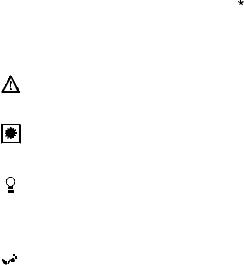
Pictograms
All the pictograms attached to the machine are shown and explained in this manual.
The operating and handling instructions are supported by illustrations.
Symbols in text
The individual steps or procedures described in the manual may be marked in different ways:
:Step or procedure without direct reference to an illustration.
Description of step or procedure that refers directly to the illustration and contains item numbers that appear in the illustration.
Example:
Loosen the screw (1) Lever (2) ...
In addition to the operating instructions, this manual may contain paragraphs that require your special attention. Such paragraphs are marked with the symbols described below:
Warning where there is a risk of an accident or personal injury or
serious damage to property.
 Warning where there is a risk of damaging the machine or individual components.


 Note or hint which is not essential for using the machine, but may improve the operator’s understanding of the situation and result in better use of the machine.

 Note or hint on correct procedure in
 order to avoid damage to the environment.
Equipment and features
This instruction manual refers to several models with different features. Components that are not installed in all models and related applications are marked thus *. Such components are available as special accessories from your STIHL dealer.
Engineering improvements
STIHL’s philosophy is to continually improve all of its products. As a result, engineering changes and improvements are made from time to time. If the operating characteristics or the appearance of your machine differ from those described in this manual, please contact your STIHL dealer for assistance.
Therefore, we cannot be responsible for changes, modifications or improvements not covered in this manual.
14 |
FG 2 |

English
Safety Precautions |
Application |
To reduce the risk of personal injury, special safety precautions must be observed while operating the filing tool.
Read the instruction manual carefully and keep it in a safe place for later reference.
Wear gloves.
It is absolutely essential to comply with the angles and dimensions specified in these instructions. If the saw chain is incorrectly sharpened – and in particular if the depth gauges are set too low – there is a risk of increased saw kickback and personal injury.
Observing the safety precautions and specifications in this manual and the instruction manual of the saw model on which the filing tool is mounted can help reduce the risk of injury and damage to the tool and saw.
The STIHL filing tool can be used to sharpen all STIHL Oilomatic saw chains with the exception of square ground chains (RSL, RSLF, RSLH) and carbidetipped chains (RD, RDS).
File correctly
–Sharpen the chain frequently, take away as little metal as possible – two or three strokes of the file are usually enough.
–Always file from the inside to the outside of the cutter.
–The file only sharpens on the forward stroke – lift the file off the cutter on the backstroke.
–Avoid touching the tie straps and drive links with the file.
FG 2 |
15 |
English
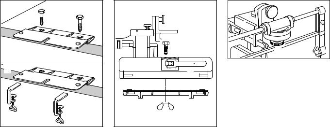
Mounting the Tool
A |
B |
564BA000 KN |
:Secure the base plate to the bench using either the wood screws (A) provided or the screw clamps (B) available as special accessories.
|
|
5 |
|
1 |
3 |
|
|
|
4 |
|
4 |
|
2 |
KN |
|
6 |
|
|
564BA001 |
|
|
|
:Place the chain rest (1) on the base plate (2) – the clamping lever (3) must face away from the bench.
:Make sure the studs (4) engage the holes.
:Fit the hex head screw (5) through the center hole from above.
:Fit and tighten down the wingnut (6) firmly.
|
7 |
|
8 |
|
KN |
9 |
564BA002 |
|
:Position the filing frame (7) on the swivel arm (8) so that the stop pin engages the slot.
:Tighten down the nut (9) firmly.
16 |
FG 2 |
English
Selecting and Fitting File |
Setting Up |
Use only special saw chain sharpening files. Other files have the wrong shape and cut and are unsuitable for sharpening saw chain.
:Select the round file (special accessory) that matches the chain pitch.
Chain Pitch |
|
Round File Ø |
|
inch |
mm |
mm |
inch |
1/4 |
6.35 |
4.0 |
5/32 |
3/8 PMN |
9.32 |
4.0 |
5/32 |
3/8 P |
9.32 |
4.0 |
5/32 |
0.325 |
8.25 |
4.8 |
3/16 |
3/8 |
9.32 |
5.2 |
13/64 |
0.404 10.26 5.5 7/32
|
1 |
|
KN |
|
|
564BA003 |
|
2 |
|
2 |
|
|
|
|
:Place the selected file (1) in the filing frame.
:Tighten down the screws (2) moderately.
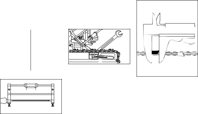
Check the Saw Chain
:Replace any damaged or worn parts of the chain and match the new parts to the shape and size of the original parts.
Clamping the Saw Chain
2 |
|
1 |
564BA004 KN |
:Place the saw chain in the chain rest
– the cutting edges must point to the right.
:Turn the clamping lever (1) to the right – the longitudinal rib on the clamping lever must face outwards.
:Tighten down the lock nut (2) moderately until the chain is locked in position.
:Turn the clamping lever to the left to release the chain and to the right to lock the chain.
Finding the Master Cutter
523BA012 KN |
The shortest cutter is used as the master cutter for filing all other cutters.
:Use a slide caliper to find the shortest cutter and mark it, e.g. with chalk.
FG 2 |
17 |
English |
A |
B |
564BA005 KN |
Turn the chain rest to suit the position of the master cutter:
:Set the chain rest as shown in illustration A if the master cutter is in the left-hand row.
:Set the chain rest as shown in illustration B if the master cutter is in the right-hand row.
The sharpening procedure described below assumes the master cutter is in the left-hand row.
The procedure is the same if the master cutter is in the right-hand row. Move the chain rest to the position shown in illustration B, reset the file, adjust angle.
Adjustments
Adjusting Filing Angle
:Check filing angle in the following table.
Chain Type |
Filing Angle |
Rapid Standard (RC) |
30 ° |
Rapid Micro (RM) |
30 ° |
Rapid Super (RS) |
30 ° |
Picco Micro (PM/PMN) |
30 ° |
RCX, RMX, PMX |
10 ° |
(ripping chain) |
|
1 |
564BA006 KN |
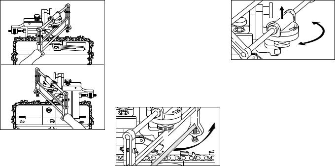
:Swing the filing frame upwards.
:Loosen the nut (1).
564BA007 KN |
:To rotate guide, lift it clear of the teeth.
18 |
FG 2 |
English
2 |
564BA008 KN |
:Set the filing angle (2) – to sharpen the left-hand row of cutters, turn the guide to the right (clockwise).
:Tighten down the nut.
|
1 |
|
3 |
KN |
|
564BA009 |
||
|
:Position the master cutter (3) below the center of the nut (1).
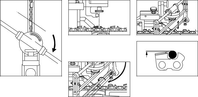
Aligning the Filing Frame
1 |
564BA010 KN |
:Position the round file (1) between the side plate and depth gauge of the master cutter by swinging and lifting the filing frame.
2 |
564BA011 KN |
 1/10 ø
564BA028 KN
:Turn the adjusting screw (2) (counterclockwise to lower file – clockwise to raise file) until about 1/10 of file diameter projects above the top plate.
FG 2 |
19 |
Loading...