


{
STIHL ADG 2
Instruction Manual
Manual de instrucciones
Warning!
Read and follow all safety precautions in Instruction Manual – improper use can cause serious or fatal injury.
Advertencia!
Lea y siga todas las precauciones de seguridad dadas en el manual de instrucciones – el uso incorrecto puede causar lesiones graves o mortales.
Instruction Manual 1 - 13
Manual de instrucciones 14 - 27
English
Contents
Printing inks contain vegetable oils, paper can be recycled.
Printed on chlorine-free paper Original Instruction Manual
© ANDREAS STIHL AG & Co. KG, 2012 0458-757-8621-A. VA2.G12. 0000004282_003_GB
Guide to Using this Manual |
2 |
Safety Precautions and Working |
|
Techniques |
2 |
Connecting Analyzer to Power |
|
Supply |
4 |
Selecting Language |
4 |
Updating Analyzer |
5 |
Testing Cordless Power Tool |
5 |
Light Emitting Diodes (LED) on |
|
Battery |
8 |
Light Emitting Diodes (LEDs) on |
|
Analyzer |
9 |
Diagnostic software |
9 |
Installing Diagnostic Software |
10 |
Connecting Analyzer to Computer |
10 |
Updating Diagnostic Software |
11 |
Using the Unit |
11 |
Storing the Analyzer |
12 |
Main Parts |
12 |
Specifications |
13 |
Troubleshooting |
13 |
Disposal |
13 |
Allowonlypersonswhofullyunderstand this manual to operate your analyzer.
This manual contains safety and operating instructions for STIHL cordlesspowertoolanalyzerADG 2.Itis importantthatyouread,understandand follow the safety precautions and the operating and maintenance instructions in chapter "Safety Precautions and Working Techniques" before using your analyzer.Forfurtherinformationyoucan go to www.stihlusa.com.
Contactyour STIHLdealer or theSTIHL distributor for your area if you do not understandanyoftheinstructionsinthis manual.
{This instruction manual is protected by copyright. All rights reserved, especially the rights to reproduce, translate and process with electronic systems.
ADG 2 |
1 |
English
Guide to Using this Manual
Pictograms
All the pictograms attached to or embossed on the machine are shown and explained in this manual.
Symbols in Text
Many operating and safety instructions are supported by illustrations.
The individual steps or procedures describedinthe manualmaybe marked in different ways:
N A bullet marks a step or procedure.
A description of a step or procedure that refers directly to an illustration may contain item numbers that appear in the illustration. Example:
N Loosen the screw (1). N Lever (2) ...
In addition to the operating instructions, this manual may contain paragraphs that require your special attention. Such paragraphs are marked with the symbols and signal words described below:
DANGER
Indicates an imminent risk of severe or fatal injury.
WARNING
Indicates a hazardous situation which, if not avoided, could result in severe or fatal injury.
2
NOTICE
Indicates a risk of property damage, including damage to the machine or its individual components.
Engineering Improvements
STIHL’s philosophy is to continually improve all of its products. As a result, engineeringchangesandimprovements are made from time to time. Therefore, some changes, modifications and improvements may not be covered in this manual. If the operating characteristics or the appearance of your machine differs from those describedinthismanual,pleasecontact your STIHL dealer for assistance.
Safety Precautions and
Working Techniques
Because this analyzer is powered by electricity, special safety precau- tions must be observed to reduce the risk of per- sonal injury.
It is important that you read, fully understand and observe the following safety precautions and warnings. Read the instruction manual and the safety precautions periodically. Careless or improper use may cause serious or fatal injury. Always read and observe the instruction manual of the cordless power tool to be tested.
 WARNING
Do not lend or rent the analyzer without the instruction manual. Be sure that anyone using it understands the information contained in this manual.
 WARNING
Minors should never be allowed to use this analyzer.
Servicing dealers can use the STIHL ADG 2 analyzer to test STIHL cordless power tools. A STIHL type AP battery is required for the test. Use only
ADG 2
geometrically matching STIHL type AP batteries with a maximum capacity of 10 Ah and a maximum voltage of 42 V.
WARNING
Donotuseitforotherpurposesbecause of the increased risk of personal injury and damage to the analyzer. Never attempt to modify the analyzer in any waysince thismayresultinaccidentsor damage to the analyzer.
WARNING
The cordless power tool's motor runs during the test. Before starting the test, alwaystakeprecautions to eliminatethe risk of accidents and injury from contact with or the operation of the power tool's attachment.
WARNING
To reduce the risk of injury, no other person may stand in the area of the power tool's motor during the test.
 WARNING
Before using your analyzer, read and fully understand all safety precautions and instructions for the STIHL AP battery and the STIHL cordless power tool you are analyzing.
Do not use defective, leaking or deformed batteries with the analyzer.
 WARNING
To reduce the risk of personal injury, do not operate the analyzer if it is damaged ornotproperlyassembled.Neverusean analyzer with a defective housing, adapter or connecting cord to the power tool or a defective power cord. Do not
ADG 2
operate the analyzer if it has received a sharp blow or been dropped until it has been properly checked.
Store analyzer out of the reach of children.
Protect from rain and dampness. Keep dry.
Use and store only indoors in dry rooms.
Connect the analyzer only to an easily accessible wall outlet with the voltage and frequency specified on the rating plate.
Operate analyzer at ambient temperatures between 41 °F (5 °C) and 104 °F (40 °C).
Never bridge the contacts of the analyzerwithmetallicobjects(e.g.nails, coins, jewelry) – short circuit. The analyzer may be damaged by a short circuit.
In the event of smoke or fire in the analyzer, disconnect it from the wall outlet immediately.
WARNING
To reduce the risk of electric shock do not insert any objects in the analyzer's cooling slots.
English
 WARNING
Do not operate in a hazardous location, i.e. in a location where there are combustible liquids (fumes), vapors or dusts. Analyzers can produce sparks, which may ignite the dust or vapors – risk of explosion.
Check the analyzer's power cord, plug, con- necting cord and adapter
regularly for damage. If the power cord or plug is damaged, immediately disconnect the plug from the wall outlet to avoid the risk of electric shock.
Never jerk the power cord to disconnect it from the wall outlet. To unplug, grasp the plug, not the cord. Have a damaged power cord repaired by an experienced electrician.
Donotusethepowercordorconnecting cord for any other purpose, e.g. for carrying or hanging up the analyzer.
Never use power cords that do not comply with regulations.
Make sure the power cord is located and/or marked so that it will not be stepped on, tripped over, come in contact with sharp edges or moving parts or otherwise subjected to damage or stress.
An extension cord should not be used unless absolutely necessary. If an extension cord must be used, plug the analyzer into a properly wired 16 gauge (AWG 16) or heavier gauge extension cord with blades that are the same number, size and shapes as the blades on the analyzer.
3
English
To reduce the risk of electric shock:
–Always connect the analyzer to a properly installed wall outlet.
–Make sure the insulation of the power cord and plug is in good condition.
Before leavingtheanalyzerunattended, transporting or storing it, remove the battery and take the adapter out of the cordless power tool.
Unplug the power cord from the outlet when analyzer is not in use.
Never store the battery in the analyzer.
Clean plastic components with a cloth. Donotuse aggressivedetergents.They may damage the plastic.
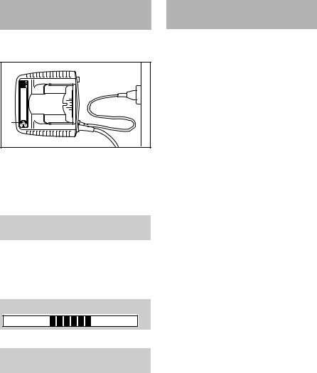
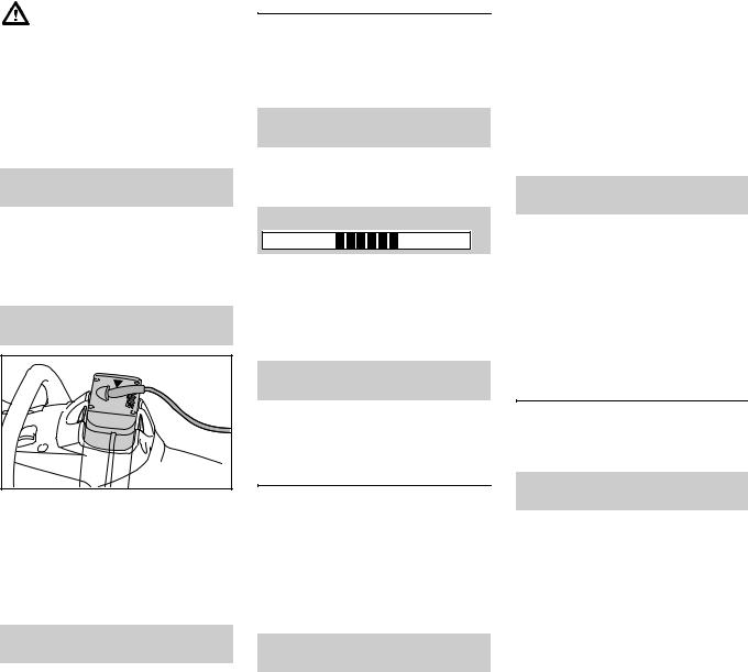
Connecting Analyzer to Power Supply
Mains voltage and operating voltage of the analyzer must be the same.
1 |
2 |
3 |
KN |
|
7BA001 |
NInsert the mains plug (1) in the wall outlet (2).
The display shows the following information as soon as the analyzer is connected to the wall outlet:
Analyzer
ADG 2
The analyzer then performs a self test. During this process the light emitting diode (3) on the analyzer glows green forabout1second,thenyellow,thenred and goes off again.
Self test
When self test is completed:
Insert battery
NInsert the battery in the analyzer – see "Testing Cordless Power Tool".
Selecting Language
NConnect the analyzer to the power supply – mains voltage and operating voltage of the analyzer must be the same – see "Connecting Analyzer to Power Supply".
NWait for analyzer to run self test – thereisnoneedtoinsertabatteryin the analyzer to select a language.
NPress the lower button on the analyzer – see "Main Parts" – for about 3 seconds to activate language selection.
NSelect required language by briefly pressing the upper or lower button.
NTo confirm the language selected, press and hold down the lower button on the analyzer for about 3 seconds.
The language can be changed at any time.
4 |
ADG 2 |
Updating Analyzer
The analyzer must be updated to cover the latest cordless power tools or new batteries and additional diagnostic functions.The update canbe performed as described below.
Direct update with diagnostic software and internet access
Computer with diagnostic software has access to internet – see "Diagnostic Software":
NConnect analyzer to the computer with the USB cable.
In the menu, click on button "Check for updates... ". The diagnostic software checkswhetheranupdateisavailable.If yes, the update is performed automatically.
Indirect update (without computer)
Data for updating the analyzer is supplied by the subsidiary.
Testing Cordless Power Tool
NConnect the analyzer to the power supply – see "Connecting Analyzer to Power Supply".
Operate the analyzer only in enclosed and dry rooms at ambient temperatures between 41°F (5°C) and 104°F (40°C).
Operating instructions
1 |
7BA005KN |
The analyzer is operated with two pushbuttons (1):
–To confirm procedures during test
–To scroll between display pages during test
–To select language
–To clear the fault memory
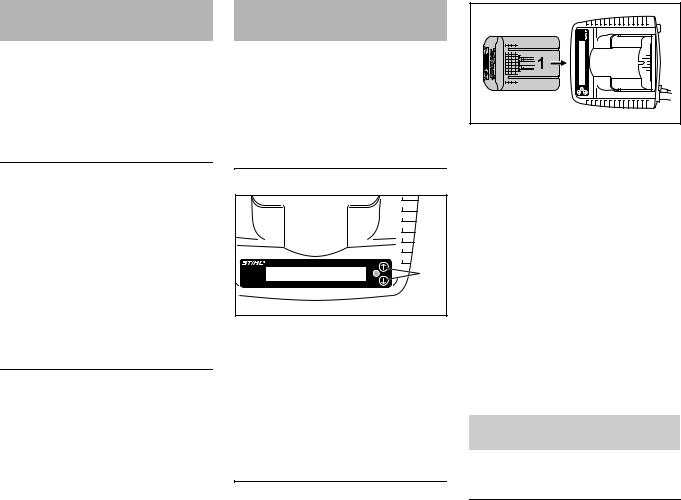
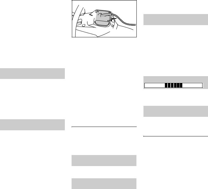
Insert battery
ASTIHLtypeAPbatterywithaminimum charge of 80% is required to test the cordless power tool. The battery suppliesthecordlesspowertoolwiththe power needed for the test.
English |
2 |
7BA002 KN |
NPush the battery (1) into the analyzer (2)untilyoufeelnoticeable resistance – then push it as far as stop.
The contacts on the battery and analyzer must be clean.
The test continues automatically when the battery is inserted. If the test does not continue, the reason may be:
–No contact between battery and analyzer – remove the battery and refit it.
–Fault in battery – test with STIHL ADG 1 battery analyzer if necessary.
If the battery's state of charge is too low, the analyzer's display shows:
State of charge too low
N Use a properly charged battery.
Insert adapter
Inserting the adapter connects the cordless power tool to the battery. The cordless power tool is ready for operation.
ADG 2 |
5 |
English
Thecordlesspowertool'smotorstartsto run during the test. Before starting the test, always take precautions to avoid the risk of injury from contact with the attachment or operation of the power tool.
The following instructions appear on the display:
Eliminate risk from tool
NEliminate risk from tool – see Technical Information bulletins on ADG 2 analyzer and the cordless power tool being tested.
N Press the lower button to confirm. Insert adapter
 1
1

 7BA003 KN
NInsert adapter (1) in power tool's battery compartment – the adapter slides into position – press it in until it engages audibly. The adapter must be flush with the top of the housing.
N Press the lower button to confirm. CAUTION: Motor may start
N Press the lower button to confirm.
6
Data transfer
The cordless power tool and analyzer communicate with each other. The analyzer can test the cordless power tool only if this data exchange functions.
Switch on unit
NSwitch on the cordless power tool for about 3 seconds – see power tool's instruction manual.
Data transfer
Ifthereisnodataexchangebetweenthe power tool and the analyzer, the problem is in the connection to the power tool – refer to Technical InformationbulletinsonADG 2analyzer and the power tool concerned.
Switch unit on again
NSwitchoncordlesspowertoolagain for about 3 seconds – the test is started.
Checking operation of controls
The controls differ according to the cordless power tool being tested. The following procedure describes the trigger switch on the FSA 85 cordless trimmer as an example.
The display always shows the current position of the control:
Operate trigger switch OFF 0%
N Operate trigger switch
Release trigger switch after a few seconds. If the trigger switch is depressed for longer the test results may be falsified or the analyzer may shut down automatically.
If the switch is in order, the display changes when the trigger is operated and the light emitting diode on the analyzer glows green:
Operate trigger switch ON 100%
Ifthedisplaydoesnotchangeoravalue of 100% is not reached with the control fully depressed, there is a fault in the control – refer to troubleshooting procedure in Technical Information bulletins on ADG 2 analyzer and the power tool concerned.
NFor further fault display, press the lower button.
Fault display
If there are no faults in the cordless power tool ...
No fault End of test
The light emitting diode on the analyzer glows continuously green.
The test is restarted by pressing the lower button.
ADG 2
If there is a fault in the cordless power tool ...
Dependingonthefault,thelightemitting diode on the analyzer glows continuously yellow or red:
–Red continuous light: Active fault, cordless power tool not ready for operation – a damage code is displayed.
–Yellowcontinuouslight:Intermittent fault in the past (e.g. loose contact), cordless power tool ready for operation – the fault can be called up in the power tool's fault memory.
Damage code
XX
The two-digit code on the display (shown as XX in the description) indicates the cause of the fault in the cordless power tool. In case of claims, always quote the code on the warranty request form.
Always remove the adapter from the power tool before starting repair.
Remove adapter before repair
ADG 2

 2 1
2 1


 7BA004 KN
NPress in both locking tabs (1) at the same time to unlock the adapter (2).
NTake the adapter (2) out of the housing.
N Press the lower button to confirm.
The data of the cordless power tool remains stored in the analyzer for about 30 minutes.
When the adapter is removed, any active faults and entries in the fault memory are shown. Scroll between the displays with the analyzer's pushbuttons. For repair procedure, see Technical Information bulletins on ADG 2 analyzer and the cordless power tool concerned.
Clearing the fault memory
The fault memory may be cleared after completing the repair.
NAfter viewing last entry in fault memory, press the lower button.
Clear memory?
Press both buttons
NPress and hold down both buttons for about 3 seconds.
Clear: no Clear: yes
English
NPress the lower button to confirm that the fault memory should be cleared.
Insert adapter, switch on unit
NInsert the adapter in the cordless power tool.
NSwitch on the cordless power tool – see power tool's instruction manual.
Fault memory is cleared. To avoid damage to the electronic module, the adapter must not be removed from the cordlesspowertoolandthebatterymust not be removed from the analyzer while the memory is being cleared.
Do not remove unit
On completion, the analyzer's display confirms that the memory has been cleared.
Memory cleared End of test
The test is restarted by pressing the lower button.
After the test
NRemove the battery from the analyzer.
Whenthebatteryisremoved,thedataof the cordless power tool that has been testedis deleted fromthe analyzer. The analyzercanthenbeusedtotestfurther cordless power tools.
7
English
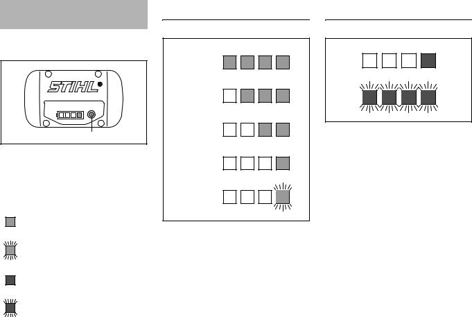
Light Emitting Diodes (LED) on Battery
Four light emitting diodes indicate the condition of the battery.
1 |
3901BA010 KN |
NPress button (1) to activate the display – the display goes off automatically after 5 seconds.
The light emitting diodes can glow or flash green or red.
Light emitting diode glows con- tinuously green.
Light emitting diode flashes green.
Light emitting diode glows con- tinuously red.
Light emitting diode flashes red.
If the green light emitting diodes glow / flash
80 - 100 %
60 - 80 %
40 - 60 %
20 - 40 %
0 - 20 % |
KN |
|
3901BA016 |
||
|
The green light emitting diodes indicate the battery's state of charge by glowing and flashing continuously.
If the red light emitting diodes glow / flash
|
4901BA008 KN |
1 light emitting diode |
Battery too |
glows continuously |
hot/cold1) |
red: |
Fault in battery2) |
4 light emitting diodes |
|
flash red: |
|
1)Remove the battery from the analyzer to cool it down/warm it up. After cooling down/warming up, restart the test – insert the battery in the analyzer.
2)Take the battery out of the analyzer and refit it again – if the LEDs still flash, the analyzer is faulty and must be replaced.
8 |
ADG 2 |
 Loading...