


{
STIHL ADG 1
Instruction Manual
Manual de instrucciones
Warning!
Read and follow all safety precautions in Instruction Manual – improper use can cause serious or fatal injury.
Advertencia!
Lea y siga todas las precauciones de seguridad dadas en el manual de instrucciones – el uso incorrecto puede causar lesiones graves o mortales.
Instruction Manual 1 - 11
Manual de instrucciones 12 - 22
English
Contents
Printing inks contain vegetable oils, paper can be recycled.
Printed on chlorine-free paper Original Instruction Manual
© ANDREAS STIHL AG & Co. KG, 2012 0458-556-8621-A. VA1.G12. 0000002393_003_GB
Guide to Using this Manual |
2 |
Safety Precautions and Working |
|
Techniques |
2 |
Connecting Analyzer to Power |
|
Supply |
4 |
Selecting Language |
4 |
Updating Analyzer |
5 |
Testing the Battery |
5 |
Light Emitting Diodes (LED) on |
|
Battery |
6 |
Light Emitting Diodes (LED) on Unit |
7 |
Diagnostic software |
8 |
Installing Diagnostic Software |
8 |
Connecting Analyzer to Computer |
9 |
Updating Diagnostic Software |
10 |
Using the Unit |
10 |
Storing the Analyzer |
10 |
Main Parts |
11 |
Specifications |
11 |
Disposal |
11 |
Allowonlypersonswhofullyunderstand this manual to operate your battery analyzer.
It is important that you read, understand and follow the safety precautions and the operating and maintenance instructions in chapter "Safety Precautions and Working Techniques" before using your battery analyzer. For further information you can go to www.stihlusa.com.
Contactyour STIHLdealer or theSTIHL distributor for your area if you do not understandanyoftheinstructionsinthis manual.
{This instruction manual is protected by copyright. All rights reserved, especially the rights to reproduce, translate and process with electronic systems.
ADG 1 |
1 |
English
Guide to Using this Manual
Pictograms
All the pictograms attached to or embossed on the machine are shown and explained in this manual.
Symbols in Text
Many operating and safety instructions are supported by illustrations.
The individual steps or procedures describedinthe manualmaybe marked in different ways:
N A bullet marks a step or procedure.
A description of a step or procedure that refers directly to an illustration may contain item numbers that appear in the illustration. Example:
N Loosen the screw (1). N Lever (2) ...
In addition to the operating instructions, this manual may contain paragraphs that require your special attention. Such paragraphs are marked with the symbols and signal words described below:
DANGER
Indicates an imminent risk of severe or fatal injury.
WARNING
Indicates a hazardous situation which, if not avoided, could result in severe or fatal injury.
2
 NOTICE
Indicates a risk of property damage, including damage to the machine or its individual components.
Engineering Improvements
STIHL’s philosophy is to continually improve all of its products. As a result, engineeringchangesandimprovements are made from time to time. Therefore, some changes, modifications and improvements may not be covered in this manual. If the operating characteristics or the appearance of your machine differs from those describedinthismanual,pleasecontact your STIHL dealer for assistance.
Safety Precautions and
Working Techniques
Because the battery ana- lyzer is powered by electricity, special safety precautions must be observed to reduce the risk of personal injury.
It is important that you read, fully understand and observe the following safety precautions and warnings. Read the instruction manual and the safety precautions periodically. Careless or improper use may cause serious or fatal injury.
WARNING
Do not lend or rent the unit without the instruction manual. Be sure that anyone using it understands the information contained in this manual.
 WARNING
Minors should never be allowed to use an engine analyzer device.
The user is responsible for avoiding injury to third parties or damage to their property.
 WARNING
Donotuseitforotherpurposesbecause of the increased risk of personal injury and damage to the unit. Never attempt
ADG 1
to modify the unit in any way since this mayresultinaccidentsordamagetothe unit.
 WARNING
Beforeusingyourbatteryanalyzer,read and fully understand all safety precautions and instructions for the STIHL AP battery.
Use only the original STIHL battery analyzer.
Use only for analyzing geomretically matchingSTIHLtype APbatterieswitha maximum capacity of 10 Ah and a maximum voltage of 42 V.
Do not test defective, leaking or deformed batteries with the STIHL battery analyzer.
Connect the unit only to an easily accessible wall outlet with the voltage and frequency specified on the rating plate.
 WARNING
To reduce the risk of personal injury, never use an analyzer with damaged housing, damaged power cord or damaged plug. Do not operate the analyzer if it has received a sharp blow, been dropped or otherwise damaged in any way.
Donotopenor dissassembleanalyzer– there are no user serviceable parts inside.
Store analyzer out of the reach of children.
ADG 1
Protect from rain and dampness. Keep dry.
Use and store only indoors in dry rooms.
Operate analyzer at ambient temperatures between 41 °F (5 °C) and 104 °F (40 °C).
Never bridge the contacts of the battery analyzerwithmetallicobjects(e.g.nails, coins, jewelry) – short circuit. The unit may be damaged by a short circuit.
In the event of smoke or fire in the unit, disconnect it from the wall outlet immediately.
WARNING
To reduce the risk of electric shock or short circuit, do not insert any objects in the unit's cooling slots.
WARNING
Do not operate in a hazardous location, i.e. in a location where there are combustible liquids (fumes), vapors or dusts. Analyzers can produce sparks, which may ignite the dust or vapors – risk of explosion.
English
Check the analyzer's power cord and plug reg- ularly for damage. If the
power cord or plug is damaged, immediately disconnect the plug from the wall outlet to avoid the risk of electric shock.
Never jerk the power cord to disconnect it from the wall outlet. To unplug, grasp the plug, not the cord. Have a damaged power cord repaired by an experienced electrician.
Do not use the power cord for any other purpose, e.g. for carrying or hanging up the unit.
Never use power cords that do not comply with regulations.
Make sure the power cord is located and/or marked so that it will not be stepped on, tripped over, come in contact with sharp edges or moving parts or otherwise subjected to damage or stress.
An extension cord should not be used unless absolutely necessary. If an extension cord must be used, plug the analyzer into a properly wired 16 gauge (AWG 16) or heavier gauge extension cord with blades that are the same number, size and shapes as the blades on the analyzer.
To reduce the risk of electric shock:
–Always connect the unit to a properly installed wall outlet.
–Make sure the insulation of the power cord and plug is in good condition.
Unplug the power cord from the outlet when unit is not in use.
3
English
Never store the battery in the analyzer.
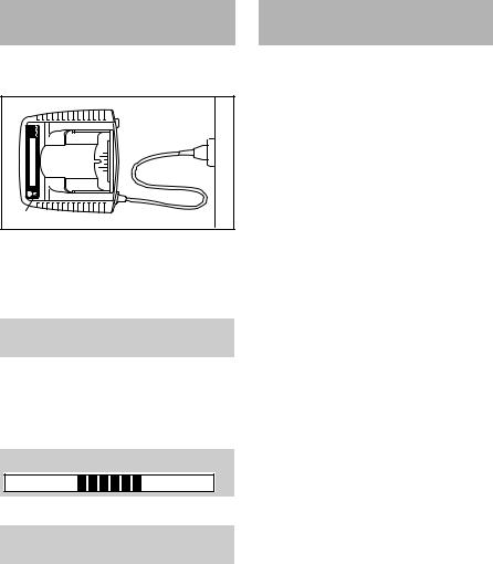
Connecting Analyzer to Power Supply
Mains voltage and operating voltage must be the same.
1 |
2 |
3 |
4901BA001 KN |
NInsert the mains plug (1) in the wall outlet (2).
The following information is displayed (shown with gray background):
Battery analyzer ADG 1
A self test is performed after the unit is connected to the power supply. During this process the light emitting diode (3) on the unit lights up green for about 1 second, then red and goes off again.
Self test
When self test is completed:
Insert the battery.
NInsert the battery in the unit – see "Testing battery".
Selecting Language
NConnect the unit to the power supply – mains voltage and operatingvoltageoftheunitmustbe the same – see "Connecting Unit to Power Supply".
NWaitforunittorunselftest–thereis noneedtoinsertabatteryintheunit to select a language.
NPress the button on the unit – see "Main Parts" – for about 3 seconds to activate language selection.
NPressthebutton(about1second)to select the required language.
NTo confirm the language selected, press the button on the unit again for about 3 seconds.
The language can be changed at any time.
4 |
ADG 1 |

Updating Analyzer
The analyzer must be updated to cover the latest cordless power tools or new batteries and additional diagnostic functions.The update canbe performed as described below.
Direct update with diagnostic software and internet access
Computer with diagnostic software has access to internet – see "Diagnostic Software":
NConnect analyzer to the computer with the USB cable.
In the menu, click on button "Check for updates... ". The diagnostic software checkswhetheranupdateisavailable.If yes, the update is performed automatically.
Indirect update (without computer)
Data for updating the analyzer is supplied by the subsidiary.
ADG 1
Testing the Battery
NConnect the unit to the power supply – see "Connecting to Power Supply".
Operate the unit only in enclosed and dry rooms at ambient temperatures between 41°F (5°C) and 104°F (40°C).
2 |
4901BA002 KN |
NPush the battery (1) into the unit (2) untilyoufeelnoticeableresistance– then push it as far as stop.
3 |
4901BA003 KN |
The test procedure begins as soon as the light emitting diodes (3) on the battery come on – see "Light Emitting Diodes (LED) on Battery".
The following information is displayed (shown with gray background):
Please wait ...
English
The battery and analyzer communicate with each other. The analyzer can only check the battery if this data exchange functions. For this reason the battery analyzer may only be used with approved STIHL batteries. This exchange of data may take several minutes.
Identification of the battery is not possible if data exchange between the battery and analyzer fails.
Battery fault |
Code: F 1 |
Battery not recognized
N Remove battery and insert it again.
Ifthesamemessageappearsagain,the battery is faulty and must be replaced.
Identification
SN: 981000602 |
|
|
|
|
|
|
|
|
Model: AP 80 |
||||||||||||||||||||
Date of man.: |
|
|
|
|
|
|
|
|
10-2008 |
||||||||||||||||||||
Meaning: |
|
|
|
|
|
|
|
|
|
|
|
|
|
|
|
|
|
|
|||||||||||
SN: |
Serial number |
||||||||||||||||||||||||||||
Model: |
Battery type (e.g. |
||||||||||||||||||||||||||||
|
|
|
|
|
|
|
|
|
|
|
|
AP 80) |
|||||||||||||||||
Date of man.: |
Month – Year |
||||||||||||||||||||||||||||
|
|
|
|
|
|
|
|
|
|
|
|
|
|
|
|
|
|
|
|
|
|
|
|
|
|
|
|
|
|
|
|
|
|
|
|
|
|
|
|
|
|
|
|
|
|
|
|
|
|
|
|
|
|
|
|
|
|
|
|
|
|
|
|
|
|
|
|
|
|
|
|
|
|
|
|
|
|
|
|
|
|
|
|
|
|
|
|
|
|
|
|
|
|
|
|
|
|
|
|
|
|
|
|
|
|
|
|
|
|
|
|
|
|
|
|
|
|
|
|
|
|
|
|
|
|
|
|
|
|
|
|
|
|
|
|
|
|
|
|
|
|
|
|
|
|
|
|
|
|
|
|
|
|
|
|
|
|
|
|
|
|
|
|
|
|
|
|
|
|
|
|
|
|
|
|
|
|
|
|
|
|
|
|
|
|
|
|
|
|
|
|
|
|
|
|
|
|
|
|
|
|
|
|
|
|
|
|
|
|
|
|
|
|
|
|
|
|
|
|
|
|
|
|
|
|
|
|
|
|
|
|
|
|
|
|
|
|
|
|
|
|
|
|
|
|
|
|
|
|
|
|
|
|
|
|
|
|
|
|
|
|
|
|
|
|
|
|
|
|
|
|
|
|
|
|
|
|
|
|
|
|
|
|
|
|
|
|
|
|
|
|
|
|
|
|
|
|
|
|
|
|
|
|
|
|
|
|
|
|
|
|
|
|
|
|
|
|
|
|
|
|
|
|
|
|
|
|
|
|
|
|
|
|
|
|
|
|
|
|
|
|
|
|
|
|
|
|
|
|
|
|
|
|
|
|
|
|
|
|
|
|
|
|
|
|
|
|
|
|
|
|
|
|
|
|
|
|
|
|
|
|
|
|
|
|
|
|
|
|
|
|
|
|
|
|
|
|
|
|
|
|
|
|
|
|
|
|
|
|
|
|
|
|
|
|
|
|
|
|
|
|
|
|
|
|
|
|
|
|
|
|
|
|
|
|
|
|
|
|
|
|
|
|
|
|
|
|
|
|
|
|
|
|
|
|
|
|
|
|
|
|
|
|
|
|
|
|
|
|
|
|
|
|
|
|
|
|
|
|
4 |
4901BA009 KN |
NFor further information, hold the pushbutton(4)depressedforabout 1 second.
5
English
If the battery is in order
Battery OK
Battery is serviceable and can be used.
NDepress push button (4) on unit for about 1 second.
Remaining capacity
80 %
Thecapacityofanewbatteryis100%.It loses capacity as it ages. This may reduce the running time of the cordless power tool.
If the battery is faulty
Battery fault |
Code: xxx |
Check warranty period
NReplace the battery – check warranty period
or |
|
|
|
Battery fault |
Code: xxx |
No warranty |
|
N Replace the battery – no warranty
The battery is subject to normal wear andtearevenduringregularoperationin accordance with instructions and, depending on the type and duration of use, has to be replaced in good time.
The three-digit code (shown as xxx in the description) indicates the cause of the faultin thebattery. In caseofclaims, always quote the code on the warranty request form.
After test
Take the battery out of the unit.
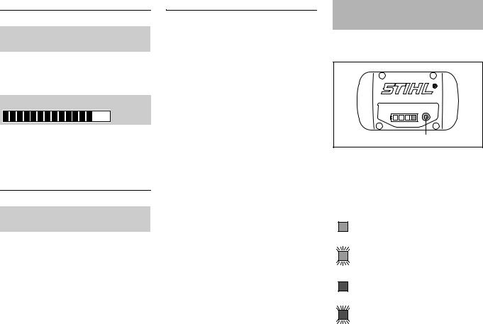
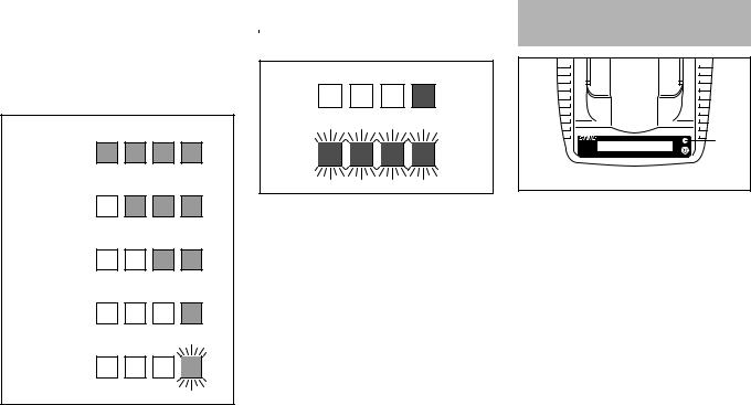
Light Emitting Diodes (LED) on Battery
Four light emitting diodes indicate the condition of the battery.
1 |
3901BA010 KN |
NPress button (1) to activate the display – the display goes off automatically after 5 seconds.
The light emitting diodes can glow or flash green or red.
Light emitting diode glows con- tinuously green.
Light emitting diode flashes green.
Light emitting diode glows con- tinuously red.
Light emitting diode flashes red.
6 |
ADG 1 |
If the green light emitting diodes light up |
|
If the red light emitting diodes glow |
/ flash continuously |
|
continuously / flash |
The green light emitting diodes indicate the battery's state of charge by glowing and flashing continuously.
80 - 100 %
60 - 80 %
40 - 60 %
20 - 40 %
0 - 20 % |
KN |
|
3901BA016 |
||
|
When the test is completed, the light emitting diodes on the battery go off automatically.
If the light emitting diodes on the battery flash or glow red – see "If the red light emitting diodes glow continuously / flash".
|
4901BA008 KN |
1 light emitting diode |
Battery too |
glows continuously |
hot/cold1) |
red: |
Fault in battery2) |
4 light emitting diodes |
|
flash red: |
|
1)Remove the battery from the analyzer to cool it down/warm it up. After cooling down/warming up, restart the test – insert the battery in the analyzer.
2)Take the battery out of the analyzer and refit it. Restart the test – if the light emitting diodes still flash, the battery is faulty and must be replaced.
English
Light Emitting Diodes (LED) on Unit
1 |
KN |
|
4901BA006 |
The light emitting diode (1) on the analyzer can glow or flash green, yellow or red.
Green continuous light
–Battery OK – see also "Light Emitting Diodes (LED) on Battery".
Yellow flashing light
–Battery type not recognized and not shown on display – but the test can be continued.
Red continuous light
... may mean the following:
–No electrical contact between battery and unit – remove and refit the battery
–Fault in battery – see also "Light Emitting Diodes (LED) on Battery".
Red flashing light
–Fault in battery analyzer – replace analyzer.
ADG 1 |
7 |
 Loading...