


 Loading...
STEPHAN
O2-AIR-ENERGY SUPPLY MODULE
STAXEL 1,5 3,5
Modul für Intensiv-Therapie
BETIEBSTUNDENZÄHLER
LÜFTER
SERVICE MANUAL
F. STEPHAN GmbH · Medizintechnik · D-56412 Gackenbach · Kirchstr. 19 · Tel. (06439) 9125-0 · Fax (06439) 9125-111 · info@stephan-gmbh.com · www.stephan-gmbh.com
STAXEL O2 and AIR |
Service Manual |
Table of contents |
|
|
2. TECHNICAL DIMENSIONS |
4 |
|
3.1 |
Production of oxygen |
5 |
3.2 |
Production of compressed air |
5 |
3.3 |
Generation of vacuum |
6 |
3.4 |
Construction |
6 |
4. INSTALLATION AND STARTUP |
7 |
|
4.1 |
Environmental conditions |
7 |
4.2 |
Startup |
8 |
5. CONTROL – AND DISPLAY ELEMENTS |
9 |
|
6.CONNECTIONS FOR OXYGEN, COMPRESSED AIR AND VACUUM10
7. |
TECHNICAL DESCRIPTION |
11 |
|
7.1 |
Description of system |
11 |
|
7.2 |
Schematic representation |
12 |
|
7.3 |
Switching attitude of the valve unit |
13 |
|
8. |
TECHNICAL DETAILS |
15 |
|
9. PERFORMANCE DATA OF STAXEL |
16 |
||
10. |
|
ERROR DETECTION SYSTEM |
17 |
11. |
|
MAINTENANCE |
18 |
12. |
GUARANTEE |
18 |
|
13. |
SERVICE |
19 |
|
|
|
1 |
|
STAXEL O2 and AIR |
Service Manual |
13.1Power supply
13.2Wiring diagram, STAXEL bottom part
13.3Wiring diagram V2A – cover of STAXEL
13.4Adjustment of the adsorber containers
13.5Technical details
19
20
21
22
25
13.5.1 Exchanging the bacteria filter and the intake filter mat (ambient air filter) |
25 |
|
13.5.2. |
Removing the top part, the rear panel and the side covers |
26 |
13.5.3 |
Removing the adsorber containers |
27 |
13.5.4. |
Removing the compressed-air-reservoir |
29 |
13.5.5. Removing the compressors |
30 |
|
13.5.6. Exchanging the outlet filter |
30 |
|
14.STAXEL SET OF SPARE PARTS FOR AN OPERATING PERIOD OF
2 YEARS |
31 |
|
15. MODULES WITH PRODUCT NUMBERS |
32 |
|
15.1 |
Pressure reservoir complete |
32 |
15.1 |
O2 – reservoir, complete |
33 |
15.3. |
O2 pressure reducer STAXEL, complete |
34 |
15.4 |
Terminal block STAXEL, bottom part |
35 |
15.5 |
Cover STAXEL, bottom part |
36 |
15.6 |
Housing lid STAXEL |
37 |
15.7. Adsorber unit, complete |
38 |
|
15.8. Adsorber manifold, complete |
39 |
|
15.9 |
Compressor unit, pre-assembled |
40 |
2
STAXEL O2 and AIR |
Service Manual |
1. General notice
The STEPHAN – S T A X E L - unit serves for the production of oxygen and compressed air as well as for the production of vacuum and is primarily designed for the operation of appliances for pediatrics and anaesthesia.
It continuously produces oxygen from the ambient atmosphere and thus offers an economocal alternative to the supply of oxygen from cylinders or the supply with liquid oxygen.
The STAXEL – basic unit is available for diverse applications:
STEPHAN STAXEL |
„PEDIATRICS“ ( for 2 respirators) |
STEPHAN STAXEL |
„ANAESTHESIA“ WITH RESPIRATOR |
Note: Upon request or order also other combinations are available
The STAXEL can be mounted on a service carriage and thus offers the greatest possible mobility and flexibility.
It is made from stainless steel and therefore extremely resistant against weathering and easy to keep in hygienic condition.
The STAXEL is available with a number of different shelves, brackets for appliances and appliances rails for attaching instruments, holding devices or vessels.
Furthermore, four earthed sockets (Schuko) (230 V) are provided on the rear panel, where diverse other appliances can be connected.
3
STAXEL O2 and AIR |
Service Manual |
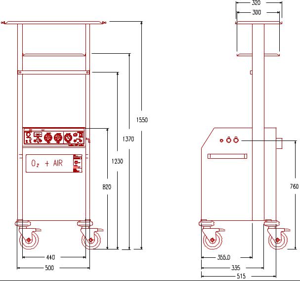
2. Technical dimensions
Modul für Intensiv-Therapie
BETIEBSTUNDENZÄHLER
LÜFTER
VAC O2 AIR
4
STAXEL O2 and AIR |
Service Manual |
3. Construction and description of performance
3.1 Production of oxygen
The production of oxygen is based upon the adsorption effect of molecular sieves. For this purpose, air which has been compressed by compressors is blown through two containers, which are filled with molecular sieves.
Since the molecules of oxygen are smaller than these of nitrogen, the oxygen can pass the sieve unimpeded, whereas the nitrogen is aborbed completely by the molecular sieve. Thus, air enriched with oxygen is obtained at the outlet of the container.
Concentration of oxygen is approximately 95 % ( with an extraction of 5 litres / min). The remaining 5 % are inert gases contained in the normal ambient atmosphere like argon, neon, xenon etc.
Of the two containers filled with molecular sieves, only one at a time takes part in the production of oxygen.
Prior to the first container being completely saturated with nitrogen, changeover to the second container, which now performs the enrichment of air with oxygen, takes place.
While the second container is in operation, the first one is cleaned, using a portion of the produced oxygen and can continue with the enrichment with oxygen, when the second container is saturated with nitrogen. This process is cyclic and continuous.
3.2 Production of compressed air
Compressed air is produced by means of the two compressors, which also compress the ambient air required for the production of oxygen. The compressed air is collected in a compressed air reservoir and is now available for the production of oxygen as well as for use as medicinal compressed air. The ambient air is hereby conducted through an intake filter and a bacteria filter and then compressed in the compressors, which both operate free of oil. Thus the production of compressed air always runs in parallel with the production of oxygen. The moment the STAXEL is switched on , it produces compressed air as well as oxygen.
5
STAXEL O2 and AIR |
Service Manual |
3.3 Generation of vacuum
Vacuum is generated by means of a vacuum pump, which is additionally installed in the STAXEL.
In parallel to the production of O2 and AIR, this vacuum pump can be switched on and off separately. Vacuum pressure is infinitely adjustable from – 0,1 to – 0,6 bar by means of a rotary knob.
3.4 Construction
The entire supply module is mounted in a sound-insulated twofold-steel housing, all rotating components, like compressor or fans are mounted oscillation-attenuated. The escaping exhaust air is evacuated via a noise-reducing filter.
The front panel of the appliance contains the displays of operating pressure for O2, AIR and VAC as well as a hours-run-meter to indicate the scheduled intervals for maintenance and servicing (exchange of filters etc).
The entire module is mounted onto a sturdy undercarriage with an appropriate holding rail, so that all STEPHAN respirators as well as reanimators (pediatrics respirator F 150 and HF 300 SIMV) can be used. The respirators can easily be detached from the unit and attached to a wall rail system or to the incubator.
Attention:
The unit must not be operated without micro filter !!
6
STAXEL O2 and AIR |
Service Manual |
4.Installation and startup
4.1Environmental conditions
The STEPHAN S T A X E L is intended for installation in dry rooms without risk of splash water or water drops. Humid or wet environment can seriously impair the reliability of the unit. Special care has to be taken to avoid placing containers filled with water or similar objects in the near vicinity.
The ambient temperature should in no case exceed+ 40° C.
With a prevailing relative air humidity it is recommended to operate the unit only in airconditioned rooms.
The air – intake grids at the rear of the unit must not be covered or obstructed with any objects.
Distance from the rear of the unit to the wall should be at least 10 cm.
The STAXEL must not be operated in rooms, where an explosion hazard exists !!
The STAXEL must not be operated in the vicinity of open fire or red hot objects because of the increased explosion hazard, which exists on account of the ambient air being enriched with oxygen of high purity.
7
STAXEL O2 and AIR |
Service Manual |
4.2 Startup
First the STAXEL is connected to the mains supply (socket).
The STAXEL has two mains switches, one mains switch for the production of O2 and AIR and a second one for the generation of vacuum.
By means of the mains switch ′O2 and AIR′ the unit is switched ON and OFF for the production of oxygen and compressed air.
Immediately after switching it on, the „STAXEL“ starts to produce oxygen and compressed air. The respective pressure gauges on the front panel, blue for oxygen and yellow for compressed air, indicate the pressure at the respective outlets.
The typical values for oxygen and compressed air are 1 bar.
By means of the mains switch ′VAC′ the unit is switched ON and OFF for the generation of vacuum.
Immediately after switching it on, the „Staxel“ starts to generate vacuum.
The pressure gauge at the front panel, white for vacuum, indicates the pressure at the respective outlet.
The typical value for vacuum is – 0,5 bar.
On both sides of the unit one connection each for oxygen and compressed air is provided. An additional connection for vacuum is provided on the right side of the unit.
During normal operation always one pair of connections ( O2 and AIR ) is used. If necessary, the „spare pair of connections“ can be used in parallel for connecting a second respirator or incubator.
8
STAXEL O2 and AIR |
Service Manual |
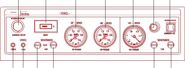
5. Control – and display elements
1 |
1.1 |
1.2 |
1.3 |
2.2 |
2.1 |
2 |
MWZ |
Modul f³r Intensiv-Therapie |
|
|
|
|
|
|
BETIEBSTUNDENZ─HLER |
|
|
|
|
|
L▄FTER
1.4 |
1.5 |
1.6 |
1.7 |
2.3 |
2.4 |
1 |
|
Mains switch ON / OFF for O2 and AIR |
|
|
|
1.1Hours – run – meter for the production of O2 and AIR
1.2Pressure gauge for indication of O2 – pressure
1.3Pressure gauge for indication of AIR – pressure
1.4Visual alarm for over – heating
1.5Visual alarm for failure of electronics or switching valves
1.6Fuse for O2 - and AIR – production
1.7Fuse for O2 – and AIR – production
2 |
Mains switch ON / OFF for VAC |
2.1Rotary knob for regulating the vacuum pressure
2.2Pressure gauge for indication of vacuum pressure
2.3Fuse for generation of VAC
2.4Fuse for generation of VAC
9
STAXEL O2 and AIR |
Service Manual |
6.Connections for oxygen, compressed air and vacuum
Outlet compressed air
Outlet oxygen
Outlet vacuum |
Strip of sockets with connecting cable |
|
VAC O2 AIR
Outlets for O2 and AIR are located on both sides of the STAXEL. The connections are quickcoupling and are are interlocked automatically after plugging in. To unplug them, the unlocking pin on the top of the connection must be depressed.
The outlet for vacuum is located at the right side. The connection consists of a 1/8“ female hose connector. The hose leading to the suction unit is slipped on.
10
STAXEL O2 and AIR |
Service Manual |
7.Technical description
7.1 Description of system
Ambient air is taken in via a microfilter, led through a silencer inlet and finally compressed in the compressors 1 + 2. The compressed air is then conducted over a condenser and cooled, before it is collected in a pressure compensation reservoir. This reservoir is provided with an exhaust valve for condensate water, which briefly opens every 45 minutes and blows the condensate water out.
The compressed air reservoir is continuously filled with compressed air from the compressors. The AIR - outlets are supplied with compressed air from this reservoir. The output pressure is limited to 1 bar by means of a pressure reducing valve. The compressors operate free of oil, thus the provided air is medicinal compressed air.
The compressed air from the pressure compensation reservoir also supplies the two adsorber containers A + B via a valve unit. The valve unit consists of a 5 / 2 – way valve, which is electronically controlled. The valve is constructed in such a way, that only one adsorber at a time takes part in the production of oxygen, while the other one is being scavenged and cleaned.
The compressed air is conducted through the adsorber containers.
The adsorber containers are filled with a special granulate, which works like a molecular sieve. On account of the different sizes of molecules, the nitrogen contained in the air is physically adsorbed, while oxygen and portions of inert gases are not adsorbed and form the residual gas atmosphere, which is led into an O2 – resrevoir.
Through a nozzle and a scavenging valve, which are located at the outlet of the adsorber containers, the adsorber not participating in the production of oxygen at this moment is blown through with a portion of the produced oxygen and the nitrogen is flushed into the atmosphere. This procedure is periodically repeated, whereby two adsorber containers are used alternatingly to increase efficiency. The two adsorber containers are interlocked against one another via two back pressure valves so that in the course of changing over to the adsorber container, which participates in the production of oxygen the produced oxygen is not completely blown through the adsorber container that has to be cleaned, but flows into the O2 – resrevoir.
The O2-outlets are supplied with oxygen from the reservoir via an additional microfilter. Pressure at the outlet is limited to 1 bar by means of a pressure reducer.
11

STAXEL O2 and AIR |
Service Manual |
7.2 Schematic representation
Microfilter
|
Pressure reducer |
O2 reservoir |
O2 outlet |
|
|
|
Back pressure valve |
Gerõusch-


Dõmpfer


Ausla▀ 


Absorber A
Scavenging valve Nozzle
Sintered filter
Absorber B
Valve unit
|
AIR outlet |
|
|
Fan |
|
|
Microfilter |
|
|
compressor 1 |
|
|
compressor 2 |
|
Pressure compensating |
Silencer intake |
|
reservoir |
||
|
Exhaust valve for condensate water
12
Loading...