

Page 1

Operation Manual
Page 2

Matthias Klag, Michael Ruf
Revision and quality control: Cristina Bachmann, Heiko Bischoff, Christina Kaboth, Insa Mingers,
Sabine
Pfeifer, Kevin Quarshie, Benjamin Schütte
This PDF provides improved access for vision-impaired users. Please note that due to the complexity
and number of images in this document, it is not possible to include text descriptions of images.
The information in this document is subject to change without notice and does not represent a
commitment on the part of Steinberg Media Technologies GmbH. The software described by this
document is subject to a License Agreement and may not be copied to other media except as
specifically allowed in the License Agreement. No part of this publication may be copied, reproduced,
or otherwise transmitted or recorded, for any purpose, without prior written permission by Steinberg
Media Technologies GmbH. Registered licensees of the product described herein may print one
copy of this document for their personal use.
All product and company names are ™ or ® trademarks of their respective holders. For more
information, please visit www.steinberg.net/trademarks.
© Steinberg Media Technologies GmbH, 2013.
All rights reserved.
Page 3

Table of Contents
4 Introduction
4 Window Overview
5 About Kits, Presets, and Groove Agent ONE
Content
6 Common Editing Methods
6 Multi Selection and Parameter Controls
7 Presets
8 Managing Your Sounds
8 Loading Kits
8 Kit Context Menu
10 Pad Section
10 Instrument Pads
14 Pattern Pads
18 Common Pad Settings
19 Pad Functions
21 Editing Kits
21 Editing Selection or All
21 Absolute and Relative Editing
22 Edit Page
44 Importing and Exporting Files
44 Importing MPC and GAK Files
44 Importing REX Files and Sliced Loops
45 Exporting Kits with Samples
45 Finding Missing Samples
47 Mixing and Effect Handling
47 Mixing
49 Effect Handling
87 Global Functions and Settings
87 Plug-in Functions Section
89 The Plug-in Name and Steinberg Logo
89 Toolbars
91 Options Page
95 Index
51 Effects Reference
51 Reverb and Delay Effects
55 EQ Effects
57 Filter Effects
62 Distortion Effects
64 Modulation Effects
72 Dynamics Effects
82 Panner Effects
83 Automation and MIDI Controllers
83 Automation
84 MIDI Controllers
3
Page 4
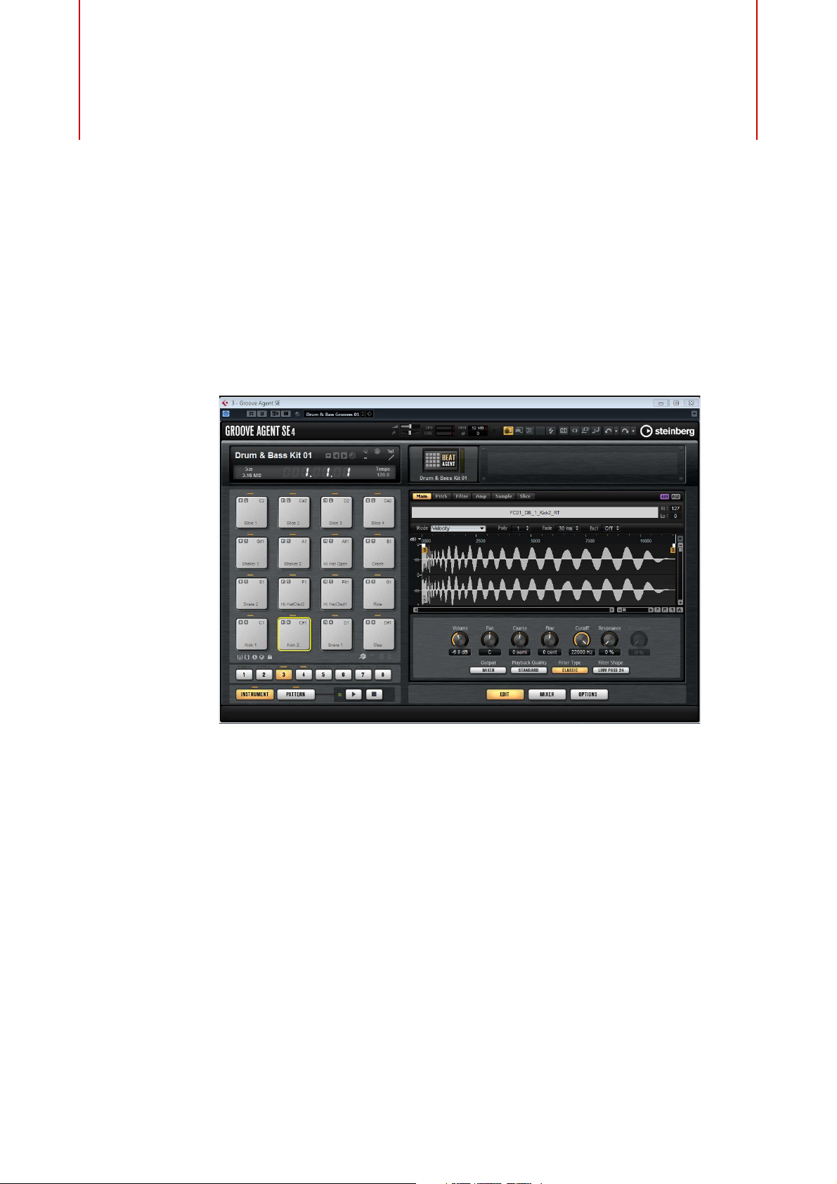
Window Overview
The application interface follows a fixed-size single window concept.
Introduction
The window is subdivided into several sections:
• The pad section on the left.
• The edit display on the right. It contains the Edit, Mixer, and Options pages.
• The plug-in functions section at the top.
• The toolbars above the edit display.
4
Page 5
Introduction
NOTE
About Kits, Presets, and Groove Agent ONE Content
About Kits, Presets, and Groove Agent ONE
Content
Kits
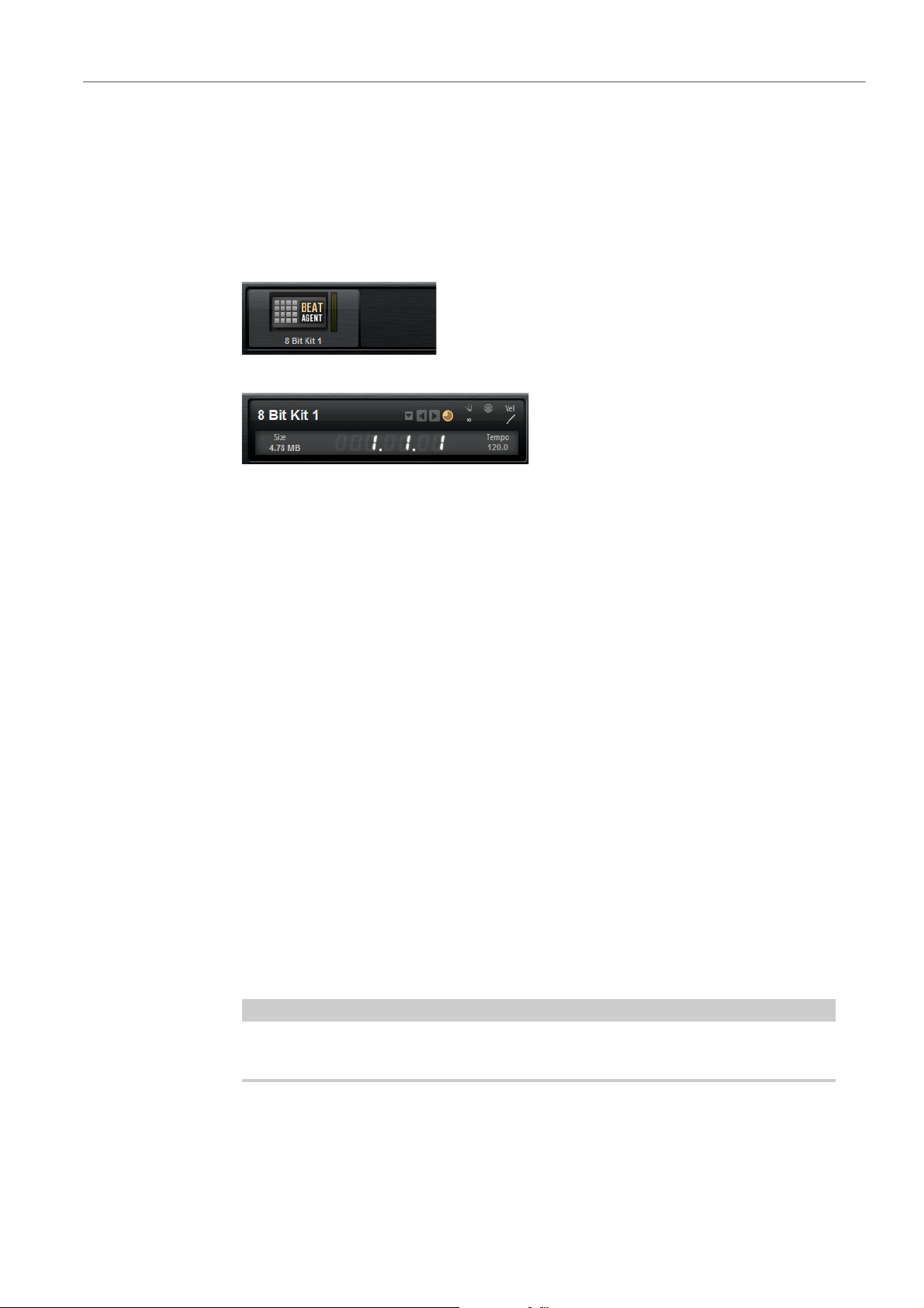
Kits can be saved and loaded via the kit rack or the kit slot section.
Kit Rack
Kit Slot Section
Kits contain all information about the kit or sliced loop and about the insert effects
that are used on the mixer channel. Kits can also contain MIDI patterns.
Sliced Loop Kits
Instead of MIDI patterns, sliced loop kits contain the MIDI phrase that is needed to
play back the loop. Other than that, sliced loop kits are similar to regular kits, in that
they can use insert effects, etc.
Plug-in Presets (VST Presets)
A plug-in preset contains all information necessary to restore the complete state of
the plug-in. This includes the kit, the MIDI patterns, as well as any insert and AUX
effects. All of these settings are also saved with the project in your host application.
Groove Agent ONE Content
Groove Agent SE can load Groove Agent ONE presets. The presets can either be
loaded as kits in the kit rack or the kit slot section or as plug-in presets via the preset
management menu in the plug-in header.
If you load a Groove Agent ONE preset as a plug-in preset, global plug-in
parameters such as AUX FX and master effects are removed and set to the default
values.
If you load a preset as a kit, all global plug-in parameters remain unchanged.
Groove Agent ONE presets always show the icon for a plug-in preset in the
MediaBay, even if they are shown in the preset loader.
5
Page 6

Common Editing Methods
NOTE
Multi Selection and Parameter Controls
To edit multiple pad parameters at the same time, select the pads that you want to
edit.
If several pads are selected and they are not set to the exact same values, most of
the controls indicate this by turning red. This is true for knobs, switches, combo
boxes, value fields, and text faders.
For example, if you have selected 3 pads with cutoff frequency values of 1200,
1400, and 2500
2500. The corresponding field shows the value of the focused pad in red.
Hz, the corona of the frequency knob shows a range from 1200 to
More complex controls, such as the envelope editors, only show the values of the
focused pad.
Adjusting the Value Ranges
You can adjust the value range of a parameter using the corona of the knob. The
values for the pads are distributed within the new range, keeping their relative
distances.
• Drag the corona to compress or expand the value range.
• [Ctrl]/[Command]-drag the corona to adjust the upper limit of the range.
• [Alt]/[Option]-drag the corona to adjust the lower limit of the range.
6
Page 7

Common Editing Methods
NOTE
NOTE
NOTE
Presets
Presets
Groove Agent SE offers two types of presets: section/module presets and VST
presets. VST presets contain all information necessary to restore the complete state
of the plug-in. Section and module presets store and recall the setup of a specific
component on the Groove Agent SE panel.
During setup, the factory presets are installed in a dedicated folder and a user folder
is created for your own presets. The handling of presets is the same throughout the
program.
Factory presets are write-protected, but may be overwritten when a software
update is executed. Presets in your user folder are never changed by the software.
Handling Section and Module Presets
The preset controls can be found throughout the program. The handling is always
the same.
• To save a preset, click the Save button (the disk icon).
You cannot overwrite factory presets. If you want to save changes made to a factory
preset, save the preset under a new name or in a new location.
• To load a preset, click the arrow icon and select a preset from the list.
• To delete a preset, click the Delete button (the trash icon). Note that factory
presets cannot be deleted.
Handling VST Presets
Loading VST Presets
1) In the header of the plug-in panel, click the Preset management button next
to the preset name field and select Load Preset.
2) Select a preset to load it. Double-click a preset to load it and close the preset
loader.
Saving VST Presets
In the header of the plug-in panel, click the Preset management button next to the
preset name field and select Save Preset.
For more information on VST presets, see the Cubase/Nuendo Operation Manual.
7
Page 8
Loading Kits
There are several ways to load kits:
• Via drag & drop from the MediaBay or the Windows Explorer/Mac OS Finder.
• Via the context menu in the kit rack.
• By clicking the Load Kit button at the right of the kit name in the kit slot
Managing Your Sounds
section.
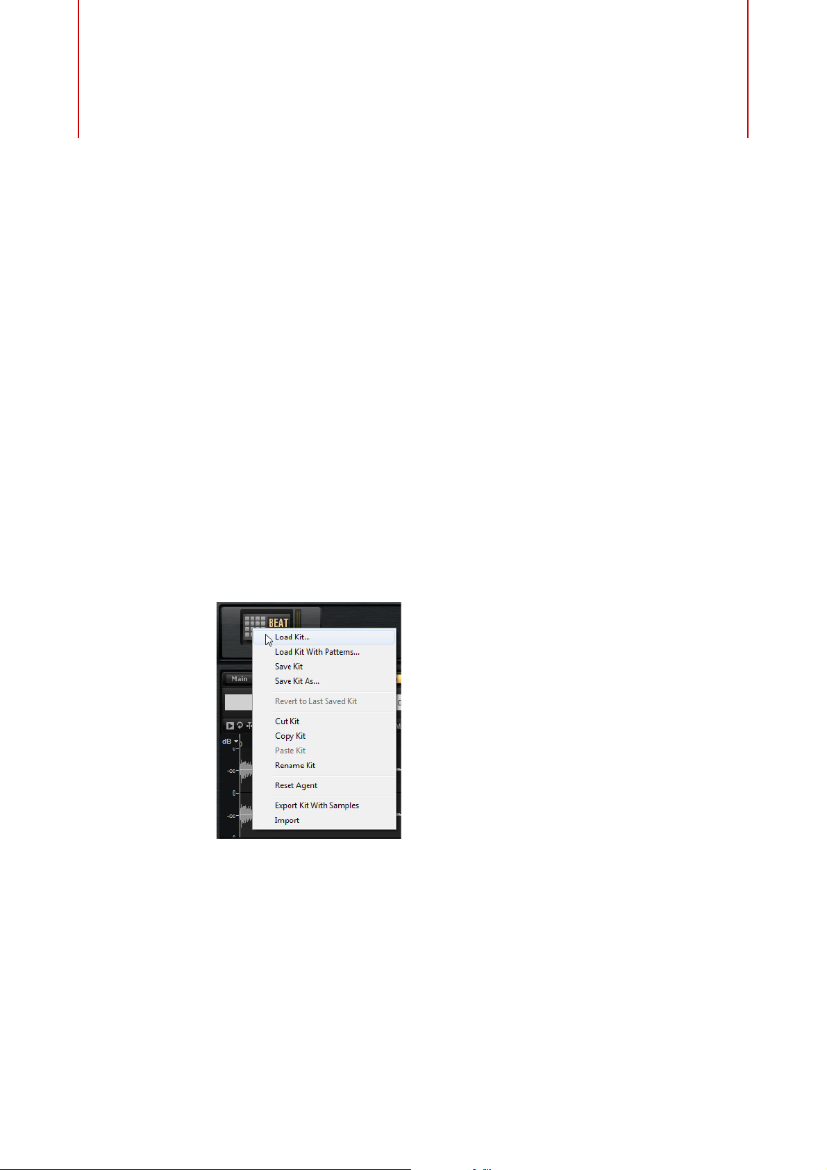
Kit Context Menu
Load Kit
Opens a pop-up menu containing the available kits. Double-click a kit to load
it.
Load Kit With Patterns
Allows you to load a kit with its MIDI patterns, if any.
Save Kit
Saves the kit. If you try to overwrite write-protected factory content, a dialog
opens that allows you to save the edited kit under a new name.
8
Page 9

Managing Your Sounds
Kit Context Menu
Save Kit As
Allows you to save the kit under a new name.
Revert to Last Saved Kit
Select this option to discard any changes made to the kit after it was loaded.
Cut Kit
Copies the kit and removes it from the slot.
Copy Kit
Copies the kit.
Paste Kit
Pastes the copied kit into the slot. If the slot already contains a kit, it is
replaced.
Rename Kit
Allows you to rename the kit.
Reset Agent
Resets the slot to the default values.
Export Kit With Samples
Exports the kit together with its associated samples.
Import
Allows you to import MPC and GAK files.
9
Page 10
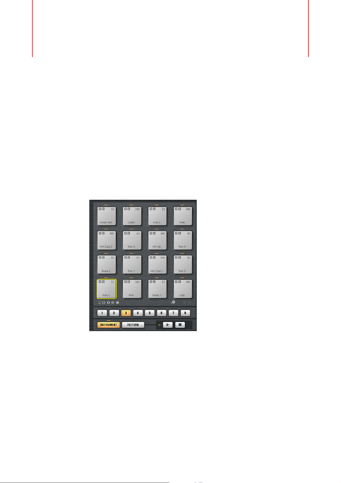
The Pad section on the left can show the Instrument pads or the Pattern pads.
To switch between the two displays, click the corresponding button below the
pads.
Instrument Pads
Pad Section
The pad section provides up to 128 pads, organized in 8 groups of 16 pads. The
instrument pads can be used to trigger sounds. Each pad is mapped to a MIDI note,
which triggers a sample. If samples are assigned to a pad, the LED above the pad
lights up.
You can switch between the groups by clicking on the group buttons below the
pads. The button of the active group is highlighted. If one or more pads of a group
have samples mapped to them, an orange LED above the group button lights up. If
a pad within a group receives a MIDI note, a green MIDI indicator LED lights up.
By default, group 3 is active when you open Groove Agent SE.
10
Page 11
Pad Section
PROCEDURE
Instrument Pads
Showing Information about the Instrument Pads
Locking Color and Output Settings
• Activate the i button below the pad section to show the following information
for the pads: the pad number, the number of samples, and the output.
• Activate the e button to show the exclusive group settings for the pads. If you
move the mouse over a pad that belongs to an exclusive group, all pads that
belong to the same exclusive group are highlighted. If a hidden pad group
contains pads that belong to the same exclusive group, a red LED above the
group button lights up.
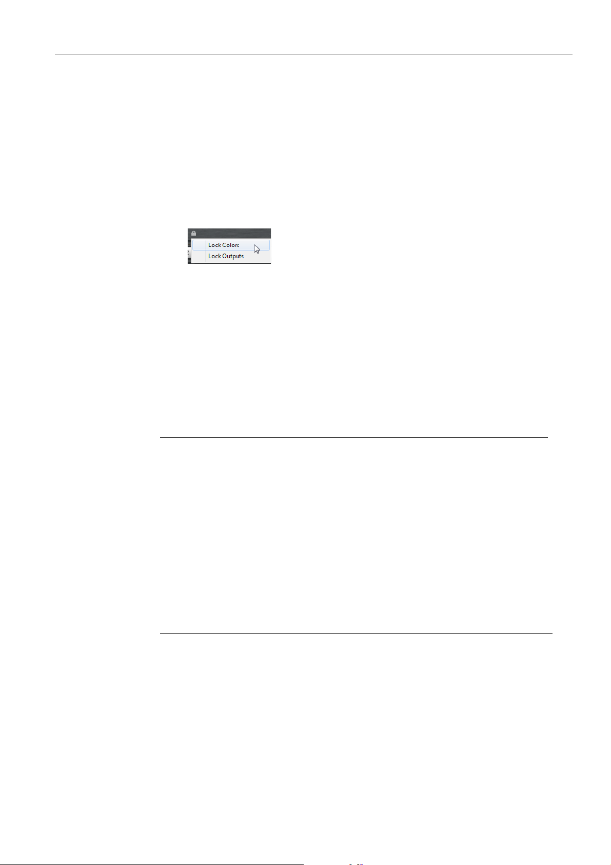
• You can lock the color and output settings for the pads. For example, this
allows you to lock the output configuration for the pads, and then switch
between kits while keeping these outputs. You can specify which parameters
you want to lock for the pads on the context menu for the Lock button below
the pads. If the button lights up, at least one setting is locked for the pads.
Using an Alternative MIDI Note Assignment
If you use an external hardware drum controller that sends specific MIDI notes for
specific instruments, you can specify an alternative MIDI trigger note mapping.
1. Activate the Use Hardware Controller Mapping button in the lower right
corner of the pad section.
Now you can load, save, and delete different trigger note configurations.
2. Specify a new trigger note for the pad.
• Right-click a pad, select Edit/Learn Trigger Note and specify the new
trigger note by entering it into the value field or by playing the
corresponding note on your hardware controller.
• On the pad context menu, open the Assign Trigger Note submenu and
select the note from the submenus.
3. Groove Agent SE jumps to the next pad. Assign a MIDI note to all the pads
that you want to use and press [Enter] to stop assigning MIDI notes.
Drag and Drop of Audio Material
You can drag one or more samples from the Explorer/Finder and from your host
application onto Groove Agent SE. Samples can be mapped to the same pad, or to
different pads.
You can drag files from the following locations:
11
Page 12
Pad Section
Instrument Pads
Assigning a Sample to a Pad
Drop Icons
•MediaBay
• Project window
• Pool
• Sample Editor (regions)
• Audio Part Editor
• LoopMash slices
To assign a sample to a pad, drag it onto the pad.
• Drag the sample onto the topmost drop icon to add it to the pad.
• Drag the sample onto the middle drop icon to replace the current sample with
the new one.
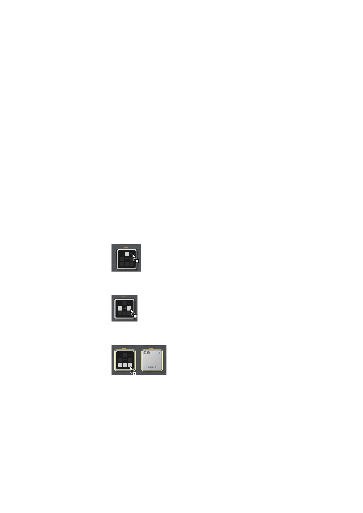
When you drag one or more samples onto a pad, the drop icons are shown. These
determine whether the samples are added to the pad, whether the current sample
is replaced with the one you are dragging, or whether the samples that you drag are
assigned to multiple consecutive pads.
• Drag samples to the topmost drop icon to add them to the pad.
• Drag one or more samples to the middle drop icon to replace the currently
assigned samples with the ones that you are dragging.
• Drag several samples to the lowest drop icon to assign them to several
consecutive pads.
A yellow border is shown around the pads that receive one of the samples.
Layering Samples on the Same Pad
You can assign up to 8 samples to a pad.
Drag & Drop to Several Pads
Rather than dropping several samples to the same pad, you can distribute samples
across the available pads in one or several groups.
12
Page 13

Pad Section
NOTE
NOTE
Instrument Pads
Replacing Individual Samples
• Select the samples, drag them onto the lowest drop icon of a pad, and drop
them.
The samples are mapped to the available pads.
How many samples can be dropped to several pads depends on the number of
available pads.
If Groove Agent SE cannot supply a sufficient number of free pads for the number
of dropped samples, a dialog is displayed, allowing you to proceed or cancel the
operation. If pads already contained samples, these are replaced.
You can replace individual samples by dragging another sample on a pad or on a
sample in the mapping view.
• To replace a sample for a pad in the pad section, drag the new sample onto
the pad until the drop option icons are shown and drop it onto the middle of
these icons.
• To replace a sample in the mapping view, drag the new sample onto a sample
in the mapping view.
The sample that will be replaced is indicated by a red rectangle.
Removing Samples From Pads
• To remove a sample from a pad, right-click the pad and select Remove
Sample from the pop-up menu.
• To remove several selected samples, right-click one of the samples and select
Remove Sample.
• To remove all samples from a pad group, right-click the group button and
select Remove All Samples.
Moving and Copying Samples between Pads
Samples can be moved and copied between pads.
To move the samples from one pad to another pad, drag the pad to either the top,
the middle, or the bottom drop icon of the destination pad.
To copy the samples instead of moving them, keep [Alt]/[Option] pressed when
dragging the samples.
13
Page 14
Pad Section
NOTE
Pattern Pads
When you copy pads that are part of a sliced loop, they are pasted as normal
instrument pads, that is, they are no longer related to the loop.
Moving and Copying Samples between Groups
To move or copy the samples to pads in another group, drag the samples on the
group button first to show the group, and then to the new pad.
The options are the same as when moving samples between pads of the same
group.
Moving Sliced Loops
You can move sliced loops with one drag and drop operation.
• Drag the first slice of the loop and move it onto the pad section.
When you start dragging, Groove Agent SE shows the pads on which the
sliced loop can be dropped, that is, the pads that are followed by enough
empty pads to insert all the slices. Pads on which the loop cannot be dropped
are grayed out.
• Drop the slice on the pad from which you want to start inserting slices.
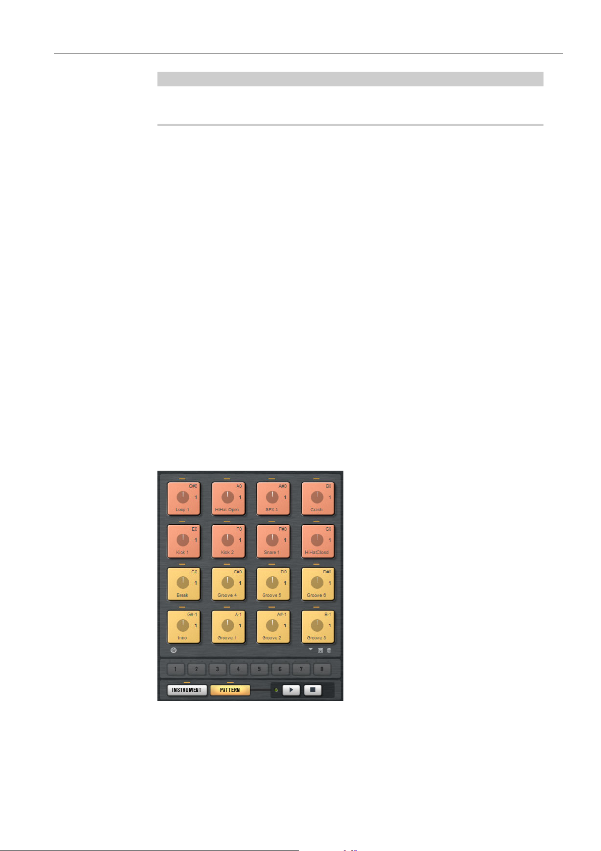
Pattern Pads
The pad section provides 16 pattern pads. Each pad is mapped to a MIDI note. You
can assign MIDI phrases to each pattern pad, to trigger complete drum patterns or
single instrument phrases, depending on the MIDI files. The pads are used to switch
between patterns.
14
Page 15

Pad Section
Pattern Pads
If a MIDI file is assigned to a pad, the pad shows a progress indicator and a beat
counter. When the pattern is triggered, the progress indicator shows the playing
progress graphically. In addition, the beat counter shows the current beat during
playback. This allows you to see which patterns are currently running and at which
playing position, relative to the length of the pattern. This can be particularly helpful
when Toggle mode is selected, because it provides a quick overview of the
patterns that will be stopped and those that will be triggered.
The Transport controls below the pads allow you to trigger the focused pattern pad
without playing a MIDI note. Click the Stop button to end playback. If you switch
between pattern pads during playback, the pattern changes according to the set
Restart Mode.
Assigning MIDI files to Pads
• Drag a MIDI file from the Explorer/Finder or from the MediaBay onto a pad.
• Drag a MIDI part from the host application onto a pad.
• Select a pad to show the editor in the edit view. Click the phrase selector and
choose one of the factory or user MIDI phrases.
• Drag a file from the Explorer/Finder onto the import field. The file is imported
to your user phrase library and assigned to the selected pad.
Assigning Multiple MIDI Files to Pads
You can also drag and drop several MIDI files at a time.
• Move the mouse over the lower part of the pad on which you want to drop the
first MIDI file.
A yellow frame indicate the pads that receive a MIDI file.
• Drop the files.
The MIDI files are imported to your user MIDI phrase library and are automatically
assigned to the pads.
Removing MIDI Files from Pads
• To remove a MIDI phrase, right-click a pad and select Remove Phrase from
the context menu.
• To remove the MIDI phrases from all selected pads right-click one of the pads
and select Remove Phrase from the context menu.
Using MIDI Port B for Pattern Pads
By default, instrument and pattern pads share the same MIDI port. If two pads are
triggered in parallel, the pattern pad always gets priority, therefore, instrument pads
that use the same trigger note as a pattern pad cannot be played via MIDI.
To be able to play all instrument and pattern pads via MIDI, assign MIDI port B to
the pattern pad section. This way, you can trigger instruments on one MIDI port and
patterns on the other.
• To use Port B, activate the Use MIDI Port B for Pattern Pads button in the
lower left corner of the pattern pad section.
15
Page 16
Pad Section
Pattern Pads
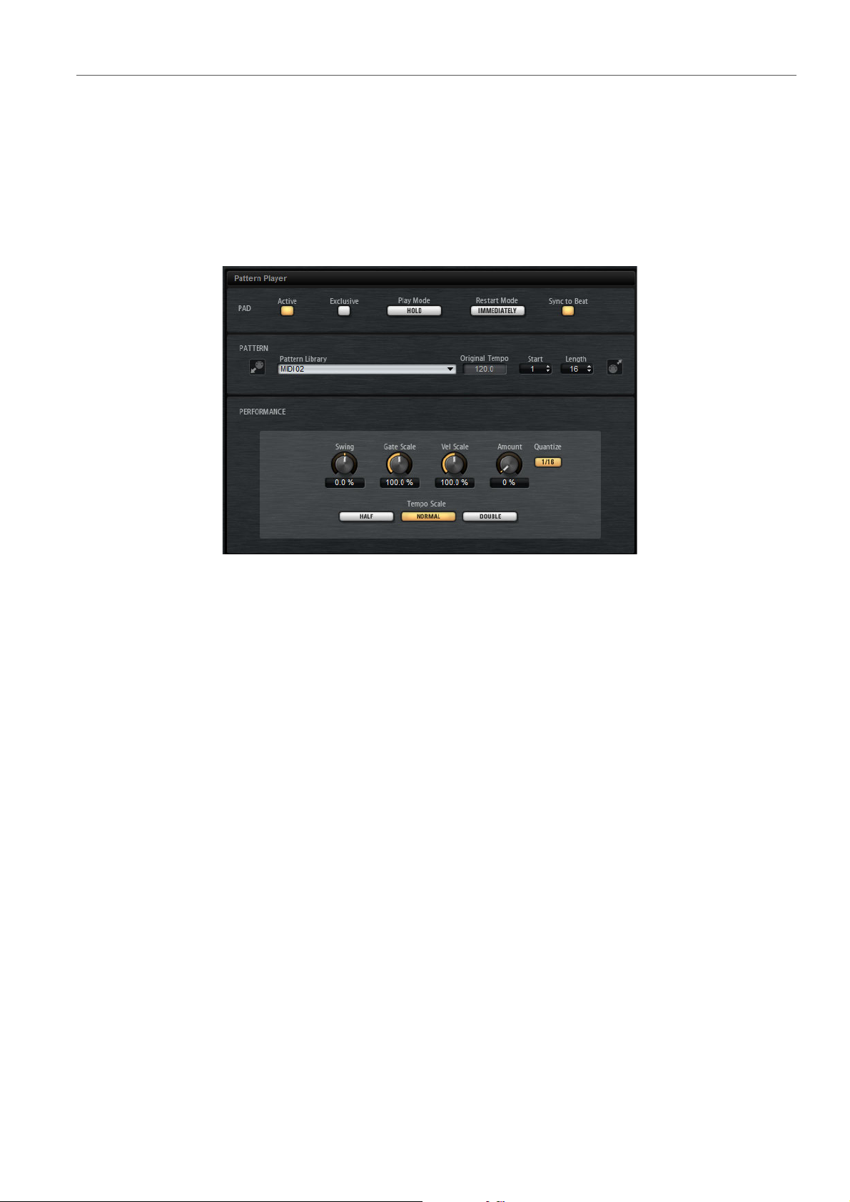
Pattern Player
The Pattern Player is where you assign a MIDI phrase to a pad and specify how it is
triggered. In addition, it provides the performance parameters, allowing you to
further modify the playback of the phrase.
The Pattern Player opens when you click a pattern pad. It is divided into the sections
Pad, Pattern, and Performance.
Pad Section
Active
Exclusive
Play Mode
Restart Mode
Activates/Deactivates playback for the pad.
To activate exclusive playback for a pad, activate this button. Triggering an
exclusive pad stops playback of the current pattern, according to the set
restart mode. Pads for which this button is not activated can play
simultaneously with other patterns.
• To play a pattern for as long as you hold down a key, select Hold.
• To start and stop playback with the trigger note for a pad, select Toggle.
Toggle mode is best used for live performances. Otherwise, it can lead
to unpredictable results, for example, when stopping and restarting
playback in the host application or when locating to another position
during playback.
Determines whether a phrase starts to play immediately, at the next beat, or
at the next full measure.
16
Page 17

Pad Section
NOTE
Pattern Pads
Sync to Beat
If Sync to Beat is activated, triggering a phrase starts the phrase in sync with
any other phrases that are playing. For example, if you trigger a phrase and
trigger the next phrase after 3 beats, this phrase starts playing at beat 3. If
Sync to Beat is deactivated, the second phrase starts from the beginning.
Pattern Section
Pattern Library
Allows you to select a MIDI pattern. Click to select the file from the list.
To access the folder where the user MIDI patterns are saved, right-click the
Pattern Library field and select
you can add, remove and rename files and create subfolders to organize your
MIDI patterns.
Pattern pads always contain the MIDI data and do not reference the original
MIDI files.
“Show in Explorer/Finder”. In this location,
Original Tempo
Displays the original tempo as saved in the MIDI file.
Start
Specifies the beat from which the phrase starts to play.
Length
Specifies the length of the phrase. Initially, this parameter is set to the original
length of the MIDI phrase.
Import Field
To import MIDI files from your file system or MIDI parts from your host
application into the user pattern library, drag them onto the MIDI import field.
You can import multiple MIDI files at the same time by dropping them on the
import field. The first file is assigned to the selected pad.
Export Field
To export a pattern, click the MIDI export field and drag it onto a MIDI track in
your host application. You can also drag the field to other locations and
applications that support MIDI files.
Import/Export and Alternative Trigger Note Mappings
If you are working with alternative trigger note mappings, this is taken into
account and the MIDI pattern is adapted automatically on import/export. This
is important if you are recording MIDI with a hardware drum controller and you
want to import MIDI parts from the host application or export patterns from
Groove Agent to the host application during that process.
If you recorded the MIDI file with the standard trigger note mapping,
deactivate alternative trigger note mapping in the Pad section.
17
Page 18

Pad Section
NOTE
Common Pad Settings
Performance Section
Swing
Allows you to shift the timing of notes on even numbered beats to give the
phrase a swing feeling. Negative values shift the timing backward, and the
notes are played earlier. Positive values shift the timing forward, and the notes
are played later.
Gate Scale
Allows you to shorten or lengthen the notes of the phrase. At a value of 100 %,
the notes play with their original gate length.
Gate Scale has no effect on samples that are played in One Shot mode. They
always sound until the end.
Velocity Scale
Raises or lowers the note-on velocities of the phrase. At a value of 100 %, the
notes are played with their original velocity.
Quantize Amount
This parameter defines how much of the quantization grid is applied. A value
of 100
note value. Smaller values move the notes only partially towards the next
Quantize note value. With a value of 0
Quantize Grid
This parameter allows you to set up a quantization grid, in fractions of beats.
You can also specify dotted and triplet values.
Tempo Scale
Defines the speed at which the phrase is running. You can choose between
half, normal, and double speed.
% means the MIDI note events play back only at the specified quantize
Common Pad Settings
• Pads show the associated MIDI note in the top right corner.
For pattern pads, you can change the MIDI note assignment. For instrument
pads, you can only change this if Use Hardware Controller Mapping is
activated.
%, no quantization is applied.
• In the lower section, the name of the pad is displayed.
• If samples are assigned to an instrument pad, the LED above the pad lights
up.
• If a MIDI file is mapped to a pattern pad, the LED above the pad lights up.
• A pad lights up if the associated MIDI note is triggered.
18
Page 19

Pad Section
Pad Functions
• A yellow frame around a pad indicates that this pad is selected for editing.
Pad Colors
You can colorize pads using up to 16 different colors. This can be used to improve
the overview of instruments within your kit. For example, you can set the bass drum
to one color, the snare to another, toms and cymbals to another, and so on.
• To apply a color to a pad or to several selected pads, open the context menu
and select a color from the Set Color submenu.
Selecting Pads
Apart from the regular selection options, you can use the additional selection
options on the pad context menu.
• Select All Pads – All 128 pads are selected.
• Select All Pads in Group – All 16 pads of the pad group are selected.
• Invert Selection – Selects all unselected pads and deselects all selected
pads.
• Invert Selection in Group – As above, but only for the pad group.
Pad Functions
• To change the name of a pad, right-click the pad, select Rename Pad from
the context menu, enter a new name and press [Enter].
This is useful if the names of the samples are either too long or not very
intuitive. Renaming pads also allows you to indicate that more than one
sample is mapped to a pad, for example.
• You can edit multiple selected pads. The first selected pad shows a yellow
frame, the rest of the selected pads a lighter yellow frame.
• To select a pad without triggering a sample or pattern, [Alt]/[Option]-click the
pad.
• In Instrument mode, the pads can be used to trigger sounds. You can trigger
them with different velocities. Velocities are lower the further down towards
the bottom of a pad you click. Clicking towards the top of the pad results in
higher velocities.
• To mute or solo an instrument pad, click the corresponding icon in the upper
left corner of a pad. Click again to unsolo or unmute.
• To unmute or unsolo all instrument pads, click the Reset All Mute/Reset All
Solo buttons below the pads.
• To remove samples from an instrument pad, right-click the pad and select
Remove All Samples from the context menu.
19
Page 20

Pad Section
Pad Functions
• To reset a pad, right-click the pad and select Reset Pad from the context
menu. To reset all 128 pads, right-click a pad and select Reset All Pads from
the context menu.
For instrument pads, this removes all samples and resets name, color, and
trigger note for the pads to their default values.
For pattern pads, this removes the MIDI file and the name from the pads and
resets color and trigger note to the default values.
20
Page 21

Editing Selection or All
NOTE
You can apply your editing either to the selection (SEL) or to all samples of the pad
(PAD), depending on the setting of the corresponding button on the toolbar.
Absolute and Relative Editing
When editing multiple samples, you can either change values absolutely for all the
samples (ABS) or make relative changes (REL), depending on the setting of the
corresponding button on the toolbar.
Editing Kits
• When you use absolute editing and you change a parameter from 50 % to
% for one sample, all other samples are also set to 60 %.
60
• When you use relative editing and you change a parameter from 50 % to 60 %
in one sample, another selected sample that was set to 70
Relative changes can be made for all parameters that can be adjusted continuously.
Changes of parameters that select one of multiple modes or switch between two
states are always absolute.
% is set to 80 %.
21
Page 22
Editing Kits
NOTE
Edit Page
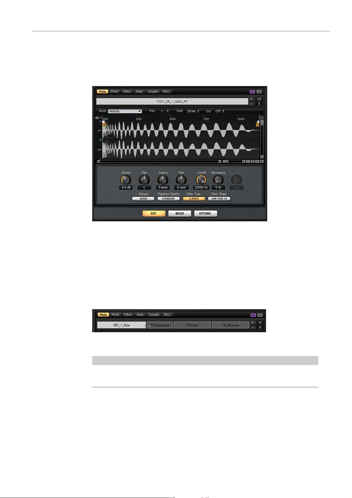
Edit Page
The Edit page is where you edit the sound of the kits.
• To open the Edit page, click the Edit button in the lower right section of the
The Edit page contains six tabs: Main, Pitch, Filter, Amp, Sample, and Slice.
Mapping View
The mapping view shows the current sample mapping of the selected pad.
You can replace and remove samples in the mapping view and adjust their velocity
ranges. The focused sample is displayed in a lighter color.
The mapping view always shows the velocity ranges, even if they are not used to
trigger samples. However, the values only have an effect in Velocity mode.
plug-in panel.
22
Page 23

Editing Kits
NOTE
NOTE
NOTE
Edit Page
Mode
Determines the trigger mode for the samples of a pad:
•In Velocity mode, the incoming velocity determines which sample is
played.
•In Layer mode, all samples are played at the same time, regardless of
their velocity.
•In Round Robin mode, the samples are played repeatedly one after the
other, from left to right.
•In Random mode, samples are played randomly. Repetitions can occur.
•In Random Exclusive mode, samples are played randomly, but
repetitions are not allowed.
Poly
Sets the maximum polyphony of a pad. For example, if this is set to 4, you can
trigger a pad 4 times before notes are stolen.
The polyphony value represents the number of notes that can sound
simultaneously, therefore triggering layered samples on a pad may lead to a
much higher number of actual sample voices.
Fade
Specifies the time it takes for a voice to fade out when voices are stolen.
You can specify different fade settings for the different samples of a pad.
Exclusive Group
This allows you to assign a pad to one of 32 exclusive groups. Pads within a
group are never played back simultaneously. When a new note is played, the
previous note stops.
Changing the Velocity Ranges of Samples
• Select the sample in the mapping view and enter new values in the Hi and Lo
fields on the right.
• Position the mouse between two samples, so that a double-arrow is shown,
and drag to the left or right.
Changing the velocity range of a sample automatically adapts adjacent samples,
that is, velocity ranges cannot overlap.
23
Page 24

Editing Kits
NOTE
Edit Page
Editing the Mapping of a Pad
A pad can contain up to 8 samples.
• You can add samples by dropping them onto the mapping view. They can be
inserted between two other samples, behind the last sample, or in front of the
first sample. This is indicated by a red insert line.
• To replace a sample, drag a new sample onto an existing sample. Which
sample will be replaced is indicated by a red frame.
• To change the order of the samples, drag them to a new position.
• To map a sample to another pad, drag it onto the pad.
This removes the sample from the current pad. To map the sample to another
pad without losing the current mapping, hold down [Alt]/[Option] while
dragging.
Main Tab
The Main tab gives you access to the sample mapping of the pad as well as to the
most important parameters, like Volume, Pan, Cutoff etc.
The Main tab also shows a simplified sample editor. You can adjust the sample start
and end markers as well as fade-in and fade-out markers and fade curves in the
display.
Volume
Sets the level of the sample.
Pan
Sets the position of the sample in the stereo panorama.
Coarse
Adjusts the tuning in semitones.
Fine
Adjusts the fine tuning in cents.
Cutoff
Controls the cutoff frequency of the filter.
Cutoff, Resonance, and Distortion are only available if a filter is used.
Resonance
Sets the filter resonance.
24
Page 25

Editing Kits
NOTE
NOTE
Edit Page
Distortion
Sets the amount of distortion. The effect of this parameter depends on the
selected filter mode.
Output
The output to which the samples are routed.
• By default, samples are routed to the Kit Mixer, where they are also sent
through the insert effects.
• You can also route samples to one of the 16 available stereo outputs.
The first stereo out is always the Master output. This output is always
active and can also contain insert effects.
• You can also route a pad directly to one of the 4 AUX channels, to
create sub groups, for example.
Samples that are routed to an output that is deactivated in your host
application are automatically sent to the Master output of the plug-in.
Playback Quality
Sets the quality.
• Standard: Select this mode to play back the samples with their original
bit depth and sample rate.
• Vintage: Select this mode to emulate the sound quality of early 12-bit
drum machines. The detuning of the samples produces the typical
aliasing effect. The sample rate is limited to 26040 Hz.
• Turntable mode is similar to Vintage mode. The samples are played
with 12bit/26040 Hz. Use this mode to emulate the typical workflow of
hip hop producers. Because the first digital drum machines only had a
very limited amount of RAM, turntables were sampled at a speed of 45
RPM instead of 33 1/3 RPM. This way, more samples could be saved
into the available RAM. During playback, the samples were tuned down,
to correct for the change in pitch. This added the typical crunch and
aliasing that the early drum machines are famous for.
If Vintage or Turntable is selected for a sample, you cannot edit the sample
using the AudioWarp functions on the Sample tab. If you try to select one of
these modes for a sample that uses AudioWarp, a warning message is
displayed.
Filter Type
Sets the filter type. You can choose between Classic, Tube Drive, Hard Clip,
Bit Reduction and Rate Reduction.
To deactivate the filter, select Off.
25
Page 26

Editing Kits
Edit Page
Filter Shape
• LP 24, 18, 12, and 6 are low-pass filters with 24, 18, 12, and 6 dB/oct.
Frequencies above the cutoff are attenuated.
• BP 12 and BP 24 are band-pass filters with 12 and 24 dB/oct.
Frequencies below and above the cutoff are attenuated.
• HP6+LP18 and HP6+LP12 are combinations of a high-pass filter with
6 dB/oct and a low-pass filter with 18 and 12 dB/oct, respectively
(asymmetric band-pass filter). Frequencies below and above the cutoff
are attenuated. Attenuation is more pronounced for the frequencies
above the cutoff.
• HP12+LP6 and HP18+LP6 are combinations of a high-pass filter with
12 and 18 dB/oct and a low-pass filter with 6 dB/oct (asymmetric
band-pass filter). Frequencies below and above the cutoff are
attenuated. Attenuation is more pronounced for the frequencies below
the cutoff.
• HP 24, 18, 12, and 6 are high-pass filters with 24, 18, 12, and 6 dB/oct.
Frequencies below the cutoff are attenuated.
• BR 12 and BR 24 are band-reject filters with 12 and 24 dB/oct.
Frequencies around the cutoff are attenuated.
• BR12+LP6 and BR12+LP12 are combinations of a band-reject filter
with 12 dB/oct and a low-pass filter with 6 and 12 dB/oct, respectively.
Frequencies around and above the cutoff are attenuated.
• BP12+BR12 is a band-pass filter with 12 dB/oct plus a band-reject
• HP6+BR12 and HP12+BR12 are combinations of a high-pass filter
• AP is an all-pass filter with 18 dB/oct. Frequencies around the cutoff are
• AP+LP6 is an all-pass filter with 18 dB/oct plus a low-pass filter with
• HP6+AP is a high-pass filter with 6 dB/oct plus an all-pass filter with
Editing the Envelope
An envelope section is available on the Pitch, Filter, and Amp tabs. Each
multisegment envelope has up to 128 nodes with the Time, Level, and Curve
parameters. The nodes and their parameters specify the overall shape of the
envelope. You can edit one or multiple nodes in the graphical envelope editor or by
entering values.
filter with 12 dB/oct. Frequencies below, above, and around the cutoff
are attenuated.
with 6 and 12 dB/oct and a band-reject filter with 12 dB/oct.
Frequencies below and around the cutoff are attenuated.
attenuated.
6 dB/oct. Frequencies around and above the cutoff are attenuated.
18 dB/oct. Frequencies around the cutoff are attenuated.
26
Page 27

Editing Kits
Edit Page
Selecting Nodes
• You select a node by clicking on it in the graphical editor. Selected nodes turn
light blue. The focused node is indicated by an orange frame. The value fields
to the left of the graphical envelope editor display the parameters of the
focused node.
• If multiple nodes are selected, you can use the Node pop-up menu to set the
focus to a different node without losing the current selection.
• [Shift]-click a node to add it to the selection. Selected nodes are edited
together.
• You can select multiple nodes by drawing a rectangle around the nodes with
the mouse.
• If the graphical editor has the focus, you can select the next or the previous
node with the left and right arrow keys.
Adjusting the Time Parameter
The Time parameter specifies the period of time between two nodes. Depending
on the Sync mode, the Time parameter is displayed in milliseconds and seconds,
or in fractions of beats.
• To set the Time parameter, select the nodes that you want to adjust and enter
a value in the Time field.
• You can also adjust the Time parameter in the graphical envelope editor, by
dragging the nodes left or right, to decrease or to increase the time span.
For a higher resolution, hold [Shift] while moving the nodes.
To limit the movement to the time axis, that is, to change only the horizontal
position of a node, hold down [Ctrl]/[Command] while dragging.
Adjusting the Level Parameter
The Level parameter specifies the amplitude of the envelope at the position set by
the Time parameter.
•To set the Level parameter, select the nodes that you want to adjust and enter
a value in the Level field.
• You can also adjust the Level parameter in the graphical envelope editor by
dragging the selected nodes up or down, to decrease or increase the levels.
For a higher resolution, hold [Shift] while moving the nodes.
To limit the movement to the level axis, that is, to change only the vertical
position of a node, hold down [Alt]/[Option] while dragging.
Adjusting the Curve Parameter
The Curve parameter allows you to adjust the curvature of the envelope curve
between two nodes from linear to logarithmic or exponential behavior.
• To set the Curve parameter, select the nodes that you want to adjust and
enter a value in the Curve field. Positive curve values change the curvature
towards logarithmic and negative values towards exponential behavior.
27
Page 28

Editing Kits
NOTE
Edit Page
• You can also adjust the Curve parameter in the graphical envelope editor by
dragging the curve between two nodes.
[Ctrl]/[Command]-click a curve to reset it to linear.
Adding and Removing Nodes
All nodes added after the sustain node always affect the release phase of the
envelope.
• To add a node, double-click at the position where you want to add the node.
• To remove a node, double-click it.
• To delete several selected nodes, press [Delete] or [Backspace].
You cannot remove the first, the last, or the sustain node.
Adding Nodes Using the Fill Function
The Fill function allows you to add multiple envelope nodes after the selected
nodes.
1) On the pop-up menu to the right of the Fill button, select the number of nodes
that you want to add.
2) In the graphical envelope editor, select the node after which you want to add
nodes.
If several nodes are selected, the new nodes are inserted after the last
selected node.
3) If the Fixed function is deactivated, the added nodes are placed with the
interval specified by the Time parameter of the selected node. If multiple
nodes are selected, the interval is specified by the focused node.
By activating Sync, you can specify the interval with the Sync note value. For
example, if 1/4 is selected, new nodes are added at exact quarter note
intervals.
4) If the Fixed function is activated, the added nodes fill the space between the
last selected node and the following one.
5) Click the Fill button.
The nodes are added.
Fixed
If Fixed is activated, only the selected nodes are moved on the time axis. If Fixed is
deactivated, all nodes that follow the edited nodes are also moved.
Snap
You can select a second envelope to be displayed in the background of the edited
envelope. If Snap is activated and you change the position of nodes, they snap to
the nodes of the envelope that is shown in the background.
28
Page 29

Editing Kits
NOTE
NOTE
Edit Page
• To specify the envelope for the background, open the pop-up menu to the
right of the Snap button and select an envelope from the list.
Using Sync
You can synchronize the envelopes to the tempo of your host application. This
allows you to set envelope times that relate to musical time intervals, regardless of
any tempo changes.
1) Click Sync to activate sync mode for the envelope.
Sync is active when the button is highlighted. A grid spaced in fractions of
beats is displayed in the graphical envelope editor.
2) On the pop-up menu located to the right of the Sync button, select a note
value.
This sets the resolution of the grid. For example, if you specify a 1/4 note
value, the nodes snap to 1/4 note steps. If the T button is activated, the note
values correspond to triplet values.
You can also enter note values and triplets manually in the value field.
The Time field of a node displays times in fractions of beats. The fraction is always
reduced to the smallest possible value. 2/16 is displayed as 1/8, for example.
Envelope nodes that do not exactly match a note value display the closest note
value.
Nodes that exactly match a note value are indicated by a red dot inside the handle
of the node. This can be useful if you switch the grid between triplets and normal
note values, for example. The triplet nodes still indicate that they match a note value,
even if the grid shows normal note values.
Selecting an Envelope Mode
You can select one of 4 envelope modes to specify how the envelope is played back
each time you hit a key. These modes are selected from the Mode pop-up menu.
The following options are available:
• Sustain: The envelope starts playback from the first node to its sustain. The
sustain level is held as long as you play the note. When you release the note,
the envelope continues with the phases after the sustain. This mode is ideal
for looped samples.
• Loop: The envelope starts playback from the first node to the loop nodes. The
loop is repeated for as long as the key is held. The envelope plays the phases
after the sustain when you release the note. This mode is ideal for adding
motion to the sustain.
• One Shot: The envelope is played from the first to the last node, even if you
release the key. The envelope has no sustain. This mode is ideal for drum
samples.
29
Page 30

Editing Kits
Edit Page
Pitch Tab
• Sample Loop: Preserves the natural attack of the sample. The decay of the
envelope does not start until the sample has reached the sample loop start.
If you set the second node to the maximum level and use the following nodes
to shape the decay during the loop phase of the sample, the envelope only
affects the loop phase. The attack of the envelope is still executed.
Coarse
Adjusts the tuning in semitones.
Fine
Adjusts the fine tuning in cents.
Random
Determines how much the pitch of a sample is changed randomly with each
note that is played.
Env Amnt
Determines how much the pitch is affected by the pitch envelope.
Level Velocity (Vel>Lev)
Determines how the velocity affects the level of the envelope. The level
depends on this parameter and on how hard you hit a key. Positive values
increase the level of the envelope the harder you hit a key. Negative values
decrease the level of the envelope the harder you hit a key.
Time Velocity (Vel>Time)
Adjusts the influence of velocity on the phases of the envelope. Positive
values decrease the times for higher velocity values. Negative values increase
the times for higher velocity values.
Segments
Here, you can select which phases of the envelope are affected by the Time
Velocity parameter.
• Attack – The velocity affects the attack only.
• Attack + Decay – The velocity affects all phases until the sustain.
• Decay – The velocity affects all phases until the sustain but without the
attack.
• Attack + Release – The velocity affects the attack and the release
phases.
• All – The velocity affects all phases.
Level Velocity Curve
You can select the curve type to specify how the incoming velocity translates
to the level of the envelope. The characteristic of each curve is displayed by
a small icon.
30
Page 31

Editing Kits
Edit Page
Filter Tab
The Filter tab allows you to adjust the tone color of the sound. The filter envelope
controls the cutoff frequency to shape the harmonic content over time.
Filter Type
Sets the filter type. You can choose between Classic, Tube Drive, Hard Clip,
Bit Reduction and Rate Reduction.
To deactivate the filter, select Off.
Filter Shape
• LP 24, 18, 12, and 6 are low-pass filters with 24, 18, 12, and 6 dB/oct.
Frequencies above the cutoff are attenuated.
• BP 12 and BP 24 are band-pass filters with 12 and 24 dB/oct.
Frequencies below and above the cutoff are attenuated.
• HP6+LP18 and HP6+LP12 are combinations of a high-pass filter with
6 dB/oct and a low-pass filter with 18 and 12 dB/oct, respectively
(asymmetric band-pass filter). Frequencies below and above the cutoff
are attenuated. Attenuation is more pronounced for the frequencies
above the cutoff.
• HP12+LP6 and HP18+LP6 are combinations of a high-pass filter with
12 and 18 dB/oct and a low-pass filter with 6 dB/oct (asymmetric
band-pass filter). Frequencies below and above the cutoff are
attenuated. Attenuation is more pronounced for the frequencies below
the cutoff.
• HP 24, 18, 12, and 6 are high-pass filters with 24, 18, 12, and 6 dB/oct.
Frequencies below the cutoff are attenuated.
• BR 12 and BR 24 are band-reject filters with 12 and 24 dB/oct.
Frequencies around the cutoff are attenuated.
• BR12+LP6 and BR12+LP12 are combinations of a band-reject filter
with 12 dB/oct and a low-pass filter with 6 and 12 dB/oct, respectively.
Frequencies around and above the cutoff are attenuated.
• BP12+BR12 is a band-pass filter with 12 dB/oct plus a band-reject
filter with 12 dB/oct. Frequencies below, above, and around the cutoff
are attenuated.
• HP6+BR12 and HP12+BR12 are combinations of a high-pass filter
with 6 and 12 dB/oct and a band-reject filter with 12 dB/oct.
Frequencies below and around the cutoff are attenuated.
• AP is an all-pass filter with 18 dB/oct. Frequencies around the cutoff are
attenuated.
• AP+LP6 is an all-pass filter with 18 dB/oct plus a low-pass filter with
6 dB/oct. Frequencies around and above the cutoff are attenuated.
• HP6+AP is a high-pass filter with 6 dB/oct plus an all-pass filter with
18 dB/oct. Frequencies around the cutoff are attenuated.
Cutoff
Controls the cutoff frequency of the filter.
31
Page 32

Editing Kits
Edit Page
Resonance
Sets the filter resonance.
Distortion
Sets the amount of distortion. The effect of this parameter depends on the
selected filter mode.
Velocity
This parameter determines the influence that velocity has on the cutoff
frequency. If Velocity is set to 0
%, the setting has no effect. At any other
value, the cutoff frequency changes with the velocity.
Env Amnt
Determines how much the filter is affected by the filter envelope.
Level Velocity (Vel>Lev)
Determines how the velocity affects the level of the envelope. The level
depends on this parameter and on how hard you hit a key. Positive values
increase the level of the envelope the harder you hit a key. Negative values
decrease the level of the envelope the harder you hit a key.
Amp Tab
Time Velocity (Vel>Time)
Adjusts the influence of velocity on the phases of the envelope. Positive
values decrease the times for higher velocity values. Negative values increase
the times for higher velocity values.
Segments
Here, you can select which phases of the envelope are affected by the Time
Velocity parameter.
• Attack – The velocity affects the attack only.
• Attack + Decay – The velocity affects all phases until the sustain.
• Decay – The velocity affects all phases until the sustain but without the
attack.
• Attack + Release – The velocity affects the attack and the release
phases.
• All – The velocity affects all phases.
R
ELATED LINKS
Editing the Envelope on page 26
Volume
Sets the level of the sample.
Pan
Sets the position of the sample in the stereo panorama.
32
Page 33

Editing Kits
Edit Page
AUX 1-4
Here, you can specify the signal level that is sent to the 4 integrated AUX FX
channels.
Level Velocity (Vel>Lev)
Determines how the velocity affects the level of the envelope. The level
depends on this parameter and on how hard you hit a key. Positive values
increase the level of the envelope the harder you hit a key. Negative values
decrease the level of the envelope the harder you hit a key.
Time Velocity (Vel>Time)
Adjusts the influence of velocity on the phases of the envelope. Positive
values decrease the times for higher velocity values. Negative values increase
the times for higher velocity values.
Segments
Here, you can select which phases of the envelope are affected by the Time
Velocity parameter.
• Attack – The velocity affects the attack only.
• Attack + Decay – The velocity affects all phases until the sustain.
Sample Tab
Toolbar
• Decay – The velocity affects all phases until the sustain but without the
attack.
• Attack + Release – The velocity affects the attack and the release
phases.
• All – The velocity affects all phases.
Level Velocity Curve
You can select the curve type to specify how the incoming velocity translates
to the level of the envelope. The characteristic of each curve is displayed by
a small icon.
The Sample tab is divided into different sections. The upper section shows the
waveform display and the lower section gives you access to all relevant sample
parameters.
The toolbar contains different tools for editing sample markers, loop markers, and
slices.
Play Sample
Activate this button to play back the raw sample.
Play Selection Looped
Activate this button to play back the selection repeatedly.
33
Page 34

Editing Kits
NOTE
Edit Page
Auto Scroll
If this button is activated, the waveform display is scrolled during playback,
keeping the playback cursor visible.
Follow Sample Playback
Activate this button to see a play locator when triggering a sample via MIDI.
Range Selection Tool
Click and drag with this tool to create a selection.
Zoom Tool
If this tool is selected, you can click in the waveform to zoom in on the position
where you click.
Play Tool
If this tool is selected, click in the waveform display to play back the sample.
It is played back from this position until you release the mouse button.
Scrub Tool
If this tool is selected, you can click in the waveform and drag sideways to play
back the audio. The playback speed depends on how fast you move the
mouse.
Snap
If the Snap button is activated, the selection start and end points and markers
snap to other markers.
Snap to Zero Crossing
If this button is activated, markers and selection start and end points are only
placed at zero crossings (positions in the audio where the amplitude is zero).
This helps you avoid pops and clicks that are caused by sudden amplitude
changes.
Edit Loop
If this icon is activated, the editor shows the looped region repeatedly instead
of the original sample data. This makes it easier to work on specific sections
of long loops, for example.
If the loop mode is deactivated when you activate the Edit Loop icon, the loop
mode is automatically set to Continuous and the loop markers are placed at
the start and end of the sample.
Show Resulting Loop Crossfade
Activate this button to see the effect of your crossfade settings in the
waveform display. If this button is activated, the resulting waveform is
displayed in red.
This button only has an effect if Edit Loop is activated.
Show Fades in Waveform (Sample tab only)
Activate this button to show your fade settings directly in the waveform.
34
Page 35

Editing Kits
Edit Page
Show Channel Sum
Activate this button to show the sum of the left and right channels in the
waveform display.
Show Left Channel
Activate this button to show the left channel in the waveform display.
Show Right Channel
Activate this button to show the right channel in the waveform display.
Preview Volume
Click this icon to display a level slider. Use the slider to specify the level for
previewing your samples.
Output
On this pop-up menu, you can specify to which plug-in output the Sample
editor sends its signals.
Ruler
The ruler shows the timeline in the specified display format.
• To select the format, click the arrow button to the right of the ruler and select
an option from the pop-up menu.
You can choose to display bars and beats, seconds, or samples.
If the Slice tab is selected, the ruler shows the timeline in bars and beats.
Waveform Display and Level Scale
The waveform display shows the waveform image of the sample. To the left of the
waveform display, a level scale is shown, indicating the amplitude of the audio.
• To select whether the level is shown as a percentage or in dB, click the level
scale label (dB or %), and select an option from the pop-up menu.
• To display the half level axes, right-click in the waveform display and select the
corresponding option on the context menu.
Parameter Section
Velocity Start Range
Determines the influence of the velocity on the sample start. Move the start
range marker to the right to start the sample later for lower velocities.
Maximum velocity starts the sample at the original sample start.
Key On Delay
With this parameter, you can delay the playback of the zone by a specified
time or a note value.
• To synchronize the delay time to the host tempo, activate the Sync
button and select a note value from the pop-up menu.
• To change the selected note value to a triplet, activate the T button.
35
Page 36

Editing Kits
Edit Page
If Sync is deactivated, the delay is specified in milliseconds. If Sync is
activated, the delay is specified in fractions of beats.
Loop Mode
• One Shot – the sample is played from start to end.
• No Loop – the sample is played for as long as the note is held.
• Continuous – the loop is played even if you release the note.
• Until Release – the loop is played for as long as the note is held and
then continues to the end of the sample.
Reverse
Reverses the sample, so that you hear it backwards.
Sample Start
The start marker of the sample.
Sample End
The end marker of the sample.
Link Sample Start and End
If this button is activated, moving the sample start also moves the sample end,
and vice versa.
Loop Start
Specifies where the loop begins. You can enter a value numerically or move
the start marker in the sample display.
Loop End
Specifies where the loop ends. You can enter a value numerically or move the
end marker in the sample display.
Link Loop Start and End
If this button is activated, moving the loop start also moves the loop end, and
vice versa.
Loop Crossfade
Specifies the time of the crossfade.
The Curve parameter defines the curve of the crossfade, from linear to equal
power.
Loop Tuning
Here you can adjust the frequency of the loop in cents.
Detune
Allows you to tune the sample by +/- 1200 cents.
Gain
Determines the level of the sample.
Pan
Determines the panorama position of the sample.
36
Page 37

Editing Kits
NOTE
NOTE
Edit Page
AudioWarp Parameters
In the AudioWarp section, you can apply time stretching and formant shifting to your
samples.
The AudioWarp functionality is not available if the playback quality is set to Vintage
or Turntable on the Main tab.
Mode
On this pop-up menu, you select the mode that is used for the AudioWarp
functions.
• Solo mode offers parameters for time stretching and formant shifting.
This mode is suitable for loops and samples with solo instruments or
vocals. It is highly efficient and supports polyphonic playback.
• Music mode offers parameters for time stretching. This mode is suitable
for complex material like drum loops and samples with mixed music. It
uses considerably more CPU time than Solo mode. Note that the more
the sample is stretched, the higher the CPU load.
•Select Off to deactivate the AudioWarp functions.
Sync Mode
The Sync modes are used to match the playback speed of the sample to the
tempo of the host application.
• If this is set to Off, you can specify the playback speed manually, in
percent.
• If this is set to Tempo, the playback speed is calculated using the ratio
between the original tempo of the sample and the tempo of the host.
• If this is set to Beats, the playback speed is calculated using the note
length of the beats, the number of beats, and the tempo of the host.
For the Sync modes to work properly, the loop of the sample has to be set up
correctly. In Tempo mode, the original tempo must be set as exactly as
possible.
Speed
This control adjusts the playback speed of the sample in percent. You can
speed up the tempo by up to 800
limit of the playback speed adjustment is 12.5
% of the original. In Music mode, the lower
%. Values below this limit have
no effect.
37
Page 38

Editing Kits
NOTE
NOTE
Edit Page
Original BPM
If Sync Mode is set to Tempo, you can enter the original tempo of the sample
in beats per minute. Groove Agent SE adjusts the playback speed of the
sample to match the tempo of the host application.
If you load a sample that contains tempo information in the file header, this
information is used to set the Original Tempo parameter. If a sample does
not contain any tempo information, the value is estimated. You can modify the
parameter values manually.
Note Length and Number of Beats
When Sync Mode is set to Beats, Groove Agent SE calculates the tempo of
the sample, based on the note length and the number of beats you enter. For
example, if the sample is a drum loop with four quarter notes, set Note to 1/4
and Beats to 4. Groove Agent SE adjusts the playback speed of the sample
to match the tempo of the host application.
Formant (Solo Mode Only)
Markers
You can use a set of different markers to specify important positions in a sample.
Sample Start
Sample End
Loop Start
If you load a sample that contains tempo information in the file header, this
information is used to set the Note Length and Number of Beats
parameters. If a sample does not contain any tempo information, the values
are estimated. You can modify the parameter values manually.
Specifies the amount of formant shifting.
Defines where the sample starts to play. Audio before this marker is ignored.
Defines where the sample stops playing. Audio after this marker is ignored.
Defines where the loop starts.
Loop End
Defines where the loop ends.
Velocity Start Range
Defines the attack phase of a sample, which can be used for the modulation
of the sample start via velocity.
38
Page 39

Editing Kits
NOTE
Edit Page
Creating Fades
• To create fades, drag the fade handles in the sample display on the Sample
tab or specify the length for fade in and fade out on the Slice tab (if you
created slices from the audio).
• To adjust the curvature, drag the fade line in the display up or down.
The fades directly influence sample playback. They are not part of the amp
envelope.
Zooming
• To zoom in/out on the time and level axis, use the horizontal and vertical zoom
• The three buttons to the right of the horizontal zoom slider allow you to zoom
• To toggle between full zoom and the previous zoom setting, click the A button
• To zoom in/out on the locator position, press [G] and [H].
• You can click and drag the ruler to zoom in/out on the position you have
sliders.
Vertical zoom slider
to the start, the end, and to the full range.
Depending on your work situation, these options refer to the sample, the
selection, or a loop. Clicking several times increases the zoom level.
to the right of the horizontal zoom slider.
clicked.
• Use the options on the Zoom submenu of the context menu.
39
Page 40

Editing Kits
Edit Page
View Range
When changing from one sample to another, you can specify which range to show
in the waveform display for the new sample.
These options can be found on the View Range submenu of the waveform display
context menu.
Auto
Follows the visible view range of the previous sample.
Last
Each sample stores the visible range individually. When you select a sample
again, its view range is restored.
Full
Shows the entire sample.
Sample
Shows the range between sample start and sample end markers.
Sample Start
Shows the sample start marker with the current zoom factor.
Sample Start Range
Shows the sample start range marker with the current zoom factor.
Sample End
Shows the sample end marker with the current zoom factor.
Loop
Shows the entire loop.
Loop Start
Shows the loop start marker with the current zoom factor.
Loop End
Shows the loop end marker with the current zoom factor.
Auditioning Samples
You can play back the sample using the Play Sample icon on the toolbar.
The following applies:
• If you have not made a selection, the whole sample is played back.
• If you have made a selection, this selection is played back.
•If the Edit Loop icon is activated, playback continues repeatedly until you
deactivate the audition function.
40
Page 41

Editing Kits
PROCEDURE
Edit Page
Making Selections
1. To make a selection, click and drag with the Range Selection tool.
•If Snap to Zero Crossing is activated, start and end of the selection are
always placed at zero crossings.
2. To resize the selection, drag its left or right border, or [Shift]-click at the
position where you want the selection to start/end.
Defining Sample Start and End from a Selection
• Make a selection, right-click in the Sample editor, open the Selection
submenu, and select Set Sample Start/End to Selection.
Defining Loop Start and End from a Selection
• Make a selection, right-click in the Sample editor, open the Selection
submenu, and select Set Loop to Selection.
Slice Tab
Toolbar
On the Slice tab, you can slice audio loops and automatically map the slices to
instrument pads. During this process, a MIDI track is created and is associated with
the first empty pattern pad.
After slicing a loop, you can play back the entire loop via the pattern pad or trigger
individual slices with the instrument pads.
The toolbar contains several tools that are also available on the Sample tab. In
addition, the following tools are available:
Play Slice
Activate this button to play back slices when clicking on them.
Lock Slices
Activate this button to prevent slice markers from being moved. Locked slices
are shown with red markers.
Jump to Previous/Next Slice
Click these buttons to jump to the next/previous slice.
BPM
Displays the tempo of the loop, as read from the sample file or calculated from
the sample length.
You can adjust this value manually.
41
Page 42

Editing Kits
Edit Page
Bars/Beats
Shows the length of the sample found by the automatic tempo detection, in
bars and beats. You can adjust this value manually, which has an effect on the
grid and the tempo.
Parameter Section
Create/Remove Slices
Click this button to create slices for the selected loop. If slices exist, click this
button to remove them.
Slice Detection Mode
The slice detection automatically sets slice markers in the sample waveform.
The following modes for slice detection are available:
• Transient mode allows you to specify the minimum peak level that a
transient needs to become a slice marker.
• Grid mode sets the slice markers according to a beat grid.
You can combine the Transient and Grid modes to detect slices that
match both conditions.
•In Manual mode, no automatic slice detection is performed. Instead,
you can add and remove slices manually by -clicking in the waveform.
Threshold
Determines the minimum level that a transient must have to be detected as
the start of a new slice.
Min Length
Determines the minimum length of a slice. Use this to avoid creating
unwanted short slices.
Grid Catch
In Transient+Grid mode, you can use this control to specify how close to the
grid a transient marker must be.
Fade In/Out
Sets the length of the fade in and the fade out for all slices of the loop.
MIDI Export Field
You can export the MIDI phrase by dragging the MIDI export field on a MIDI
track in your host application.
Slicing a loop
PREREQUISITE
To slice a loop, it is best to start with an empty kit.
42
Page 43

Editing Kits
NOTE
PROCEDURE
NOTE
Edit Page
The maximum number of slices is 128. Therefore, it is recommended to start on a
pad that is assigned to a lower note, so that enough empty pads are available.
1. Drop the audio loop on the instrument pad that you want to start with.
If the number of slices exceeds the number of available pads, some slices cannot be
mapped to instrument pads. These slices are shown in red in the waveform display.
In this case, the loop plays only with the length of the mapped slices.
2. Open the Slice tab and click Create Slices.
3. Adjust the parameters on the Slice tab to create the best set of slices.
Any changes that lead to more or less slices will create slices on or remove slices
from pads.
Adding and Removing Slices
• To add a slice marker, [Alt]/[Option]-click in the editor.
• To remove a slice marker, [Alt]/[Option]-click it.
The number of slices that can be created is limited to the number of available empty
instrument pads.
43
Page 44

Importing and Exporting Files
NOTE
Importing MPC and GAK Files
You can import AKAI MPC 500 and MPC 1000 files and GAK files created in
Groove Agent ONE into Groove Agent SE.
Importing Files Using Drag & Drop
• To import a file, drag it from the Explorer/Finder onto the slot in the kit slot
section or on the kit name in the kit rack.
Importing Files via the Context menu
You can also import files via the kit context menu.
1) Right-click the kit in the kit rack or the kit slot section and select Import.
2) Select the file that you want to import and click OK.
When importing GAK files, you will be asked to specify the folder in which to save
the included files.
Importing REX Files and Sliced Loops
You can import REX files and sliced audio parts from Cubase/Nuendo into Groove
Agent SE.
• To import a REX file or a sliced audio part into Groove Agent SE, drop it onto
an empty pad.
The slices are automatically distributed across the pads, and a MIDI phrase is
created and assigned to the first empty pattern pad.
Once the file is imported, you can trigger the slices with the instrument pads, or play
back the entire loop by triggering the pattern pad.
Imported REX files and sliced audio parts are treated like audio loops that were
sliced in Groove Agent SE.
44
Page 45

Importing and Exporting Files
NOTE
NOTE
PROCEDURE
NOTE
Exporting Kits with Samples
Pads that are part of the sliced loop display a loop icon. The pad that contains the
first slice displays a larger loop icon.
If the number of available pads is not high enough to map all slices to pads, the
slices that could not be added are shown in red on the slice edit page. You can
move pads using drag and drop to free the necessary pads. As soon as enough
pads are available, the slices that could not be mapped are automatically added.
If you import a REX file, the Slice Mode in the slice editor is automatically set to
Manual, to preserve the slice markers specified in the REX file. Note, however, that
in some cases, the slices saved in a REX file may not represent a useful audio loop.
Exporting Kits with Samples
Groove Agent SE kits can be exported together with the associated samples.
1. Right-click the kit in the kit bar and select Export with Samples from the
context menu.
2. In the dialog, specify a name and a location for the file.
RESULT
The kit file is created together with a folder containing the samples.
Samples that are part of the protected factory content cannot be exported.
Finding Missing Samples
There might be situations where loaded programs cannot find the samples they use.
This can happen if the referenced samples are located on a different drive and the
drive name has changed, or because the program was created on a different
computer system.
When this happens, the Find Missing Sample dialog opens, showing a list of all
samples that are missing, with additional information about the format, size, and
creation date. The list groups all samples that are located in the same subfolder.
45
Page 46

Importing and Exporting Files
NOTE
Finding Missing Samples
Entering a Search Path
In the Find Missing Sample dialog, below the list of missing samples, you can enter
the search path to find the missing samples.
All subdirectories are searched before the results are displayed, therefore the
search takes longer if you specify entire drives.
Starting the Search
Once you have specified the search path, click the Start Search button to start the
search process.
If the search only finds a single result for each missing sample, the sample path is
automatically corrected in the program and the sample disappears from the
Missing Files list. If all samples are found, the dialog is closed.
Multiple Results
If sample files with the same name are found in more than one location, an additional
Found File list appears below the Missing File list. This shows the available
samples and their file locations.
• To select a sample or a complete folder that is to be used to resolve the
missing samples, double-click it in the Found Files list.
Each sample or folder that is resolved this way disappears from the Missing
File list.
Once all samples are resolved the dialog closes.
Favorite Paths
If a path might be helpful for future searches, you can add it to the search path list.
The next time the dialog opens, it allows you to select one or multiple predefined
paths to specify which places to include in the search.
• To add a path, click the + sign.
Search Options
By default, Groove Agent SE searches for samples that do not only have the same
file name, but also correspond in terms of time, size, and format information. A
sample is considered
can exclude this information by activating the Ignore File Time and Size and
Ignore Audio Format options.
“found” only if all of the information is identical. However, you
46
Page 47

Mixing and Effect Handling
Mixing
Mixer Page
Kit Mixer
The Mixer page contains tabs for the Kit mixer, the AUX mixer, and the Master
mixer.
The Kit mixer contains the channel strip for the bus that is assigned to the kit slot.
Level
The level fader allows you to adjust the volume of the slot.
Pan
Sets the position of the slot in the stereo panorama.
Mute
Activate this to mute the slot.
Meter
The meters of the mixer channel show the output level of the kit.
Peak Level Meter
The meter indicates the highest level on the bus in dB. To reset the peak
meter, click on the value field.
Effect Slots
You can use the 4 slots on the right of the channel strip to add insert effects
to the slot.
47
Page 48

Mixing and Effect Handling
Mixing
AUX Mixer
Groove Agent SE features 4 AUX busses that can be used to realize classic send
effects. Each bus hosts up to 4 insert effects, which allows you to set up complex
effects. The busses can be routed to the Master output of the plug-in or to one of
the individual outputs.
Output
On this pop-up menu, you can select one of the 16 available outputs for the
AUX bus.
Mute
Level
Effect Slots
Master Mixer
The Master mixer shows the channel for the Master stereo output bus. It can host
up to 4 insert effects, that can be used to add a global EQ or compressor to the
signal chain, for example.
Mutes the AUX bus.
Allows you to set the level of the AUX bus.
You can use the 4 slots on the right of each channel strip to add insert effects
to the slot.
Level
Allows you to set the level of the Master bus.
Effect Slots
You can use the 4 slots on the right to add insert effects to the slot.
48
Page 49

Mixing and Effect Handling
Effect Handling
Effect Handling
Groove Agent SE features 4 AUX busses that can be used to realize classic send
effects. Each bus hosts up to 4 insert effects, which allows you to set up complex
effects. The busses can be routed to the Master output of the plug-in or to one of
the individual outputs.
The Kit Mixer provides access to the mixer channel of the kit which also features 4
inserts.
Furthermore, the Mixer provides access to the master output bus. This can be used
to add a global EQ or compressor to the signal chain, for example.
Default Effect Settings
Each effect comes with factory default settings. However, you can save your own
default settings for each effect as a preset.
• Set up the effect.
•Click the Save Preset button in the title bar of the effect section and save the
preset under the name
The preset is saved in the presets folder of the effect and is loaded each time you
load the effect.
• To return to the factory default settings, delete your default preset.
Using the Insert Effect Slots
On the Mixer page, you can set up insert effects for the kit channel and the the AUX
busses.
Each bus provides 4 slots for insert effects.
• To assign an insert effect, click the effect slot and select the effect from the
menu.
• To remove an insert effect including its current settings, click the effect slot
and select None from the menu.
• To bypass an effect, activate the Bypass button above the slot. Bypass is
active when the button lights up.
“--Default--”.
• To edit an insert effect, click the e button of the corresponding slot. You can
edit only one effect at a time. The parameters of the insert effect are displayed
in the bottom section.
• To move an effect to another slot, move the mouse below the edit button until
the drag icon appears and drag it to another slot. This replaces any effect
loaded in this slot.
• To change the order of the effects, move the mouse below the edit button until
the drag icon appears and drag it to a new position between two slots.
49
Page 50

Mixing and Effect Handling
Effect Handling
• To copy an effect into another slot, hold down [Alt]/[Option], move the mouse
• To copy an effect and insert it between two effect slots, hold down
below the edit button until the drag icon appears and drag it onto the new slot.
This replaces any effect loaded in this slot.
[Alt]/[Option], move the mouse below the edit button until the drag icon
appears and drag between two slots.
50
Page 51

Effects Reference
Reverb and Delay Effects
Reverb
This effect produces a high-quality algorithmic reverb with early reflections and
reverb tail.
The early reflections are responsible for the spatial impression in the first
milliseconds of the reverb. For emulating different rooms, you can choose between
different early reflections patterns and adjust their size. The reverb tail, or late
reverberation, offers parameters for controlling the room size and the reverb time.
You can adjust the reverb time individually in 3 frequency bands.
Predelay
Determines the amount of time between the dry signal and the onset of the
reverb. With higher predelay values, you can simulate larger rooms.
Early Reflections
Here, you select an early reflections pattern. The early reflections pattern
contains the most important delays that deliver the key information for the
spatial impression of the room.
ER/Tail Mix
Sets the level balance between the early reflections and the reverb tail. At a
setting of 50
below 50
source moves towards the front of the room. Settings above 50
tail and lower the early reflections, as a result the sound source moves
towards the back of the room.
%, early reflections and tail have the same volume. Settings
% raise the early reflections and lower the tail, as a result the sound
% raise the
51
Page 52

Effects Reference
Reverb and Delay Effects
Size
Adjusts the length of the early reflections pattern. At a setting of 100 %, the
pattern is applied with its original length and the room sounds the most
natural. At settings below 100
%, the early reflections pattern is compressed
and the room is perceived smaller.
Low Cut
Attenuates the low frequencies of the early reflections. The higher this value,
the less low frequencies are present in the early reflections.
High Cut
Attenuates the high frequencies of the early reflections. The lower this value,
the less high frequencies the early reflections will have.
Delay
Delays the onset of the reverb tail.
Room Size
Controls the dimensions of the simulated room. At a setting of 100 %, the
dimensions correspond to a cathedral or a large concert hall. At a setting of
50
%, the dimensions correspond to a medium-sized room or studio. Settings
below 50
% simulate the dimensions of small rooms or a booth.
Main Time
Controls the overall reverb time of the tail. The higher this value, the longer the
reverb tail will decay. At a setting of 100
%, the reverb time is infinitely long.
The Main Time parameter also represents the mid band of the reverb tail.
High Time
Controls the reverb time for the high frequencies of the reverb tail. With
positive values, the decay time of the high frequencies is longer. With negative
values, it is shorter. Frequencies are affected depending on the High Freq
parameter.
Low Time
Controls the reverb time for the low frequencies of the reverb tail. For positive
values, low frequencies decay longer and vice versa. Frequencies will be
affected depending on the Low Freq parameter.
High Freq
Sets the cross-over frequency between the mid and the high band of the
reverb tail. You can offset the reverb time for frequencies above this value
from the main reverb time with the High Time parameter.
Low Freq
Sets the cross-over frequency between the low and the mid band of the
reverb tail. The reverb time for frequencies below this value can be offset from
the main reverb time with the Low Time parameter.
Shape
Controls the attack of the reverb tail. At a setting of 0 %, the attack is more
immediate, which is a good setting for drums. The higher this value, the less
immediate the attack.
52
Page 53

Effects Reference
Reverb and Delay Effects
Multi Delay
Density
Adjusts the echo density of the reverb tail. At a setting of 100 %, single
reflections from walls cannot be heard. The lower this value, the more single
reflections can be heard.
High Cut
Attenuates the high frequencies of the reverb tail. The lower this value, the
less high frequencies the reverb tail will have.
Width
Adjusts the output of the reverb signal between mono and stereo. At a setting
%, the output of the reverb is mono, at 100 % it is stereo.
of 0
Mix
Sets the ratio between the dry and the wet signal.
This effect produces delays, with adjustable time, feedback, and filters.
With the Mode parameter, you can set up this effect as Stereo, Cross, or
Ping-Pong delay effect. Depending on the selected mode, the echoes repeat in
varying patterns across the stereo panorama.
Mode
Multi Delay offers three different modes:
• Stereo mode has two independent delay lines, one for the left and one
for the right audio channel, each with a feedback path of its own.
• Cross mode has two delay lines with cross feedback. Cross feedback
means that the delay of the left channel is fed back into the delay of the
right channel, and vice versa.
• Ping-Pong mode mixes the left and right input channel and sends it to
hard-panned left and right delays. This way, the echoes bounce like a
ping-pong ball between left and right in the stereo panorama.
Time
Sets the overall time for the left and right delay. Use the Delay L/R parameter
to shorten the time for the left or right delay. Activate Sync to set the delay
time as a note value.
53
Page 54

Effects Reference
NOTE
NOTE
Reverb and Delay Effects
Sync
Activate Sync to synchronize the delay time to the host tempo. When Sync is
activated, the time is set as a note value.
The maximum delay time is 5000 ms. If the note length exceeds this value, it
is automatically shortened.
Delay L/R
Offsets the time of the left or right delay from the overall delay time. At a factor
of 1, the right or left delay time has the same length as the overall delay time.
At a factor of 0.5, the time is half as long as the overall delay time. To offset
the left delay time, turn the control to the left. To offset the right delay time,
turn the control to the right.
Feedback
Sets the overall amount of feedback for the left and right delay. Feedback
means that the output of the delay is fed back to its input. At a setting of 0
you hear one echo. At a setting of 100
%, the echoes repeat endlessly.
%,
Feedback L/R
Offsets the amount of feedback of the left or right delay from the overall
feedback. A factor of 1 means that the amount of feedback corresponds to
the overall feedback. A factor of 0.5 means that the amount is half the overall
feedback. To offset the left feedback, turn the control to the left. To offset the
right feedback, turn the control to the right.
This parameter is only available in Stereo mode.
Filter Low
Attenuates the low frequencies of the delays.
Filter High
Attenuates the high frequencies of the delays.
Mix
Sets the ratio between the dry and the wet signal.
54
Page 55

Effects Reference
EQ Effects
EQ Effects
Studio EQ
Studio EQ is a high-quality 4-band parametric equalizer.
With the 4 frequency bands, you can shape the tone color, to create a brighter or
darker sound, for example. The two mid-range bands act as peak filters and the low
and high bands act as shelving filters. All bands are fully parametric with adjustable
gain, frequency, and Q factor.
Each frequency band offers the following controls:
Gain
Sets the amount of cut or boost for the corresponding band.
Freq
Sets the frequency that is cut or boosted with the Gain parameter.
Q (Quality)
Use this parameter to adjust the bandwidth of the mid-range peak filters from
wide to narrow. By increasing the Q value on the low and high shelving filters,
you can add a dip to their shape.
• To adjust the parameters Gain and Freq simultaneously, drag the points in the
EQ curve display.
55
Page 56

Effects Reference
EQ Effects
Graphic EQ
Graphic EQ is an equalizer with ten frequency bands that can be cut or boosted by
up to 12
dB. In addition, you can specify the overall range and output of the
equalizer.
Output
Controls the overall output level of the equalizer.
Mode
Allows you to add color or character to the equalized output. The following
options are available:
• True Response mode uses serial filters with accurate frequency
response.
• Classic mode uses parallel filters where the resonance depends on the
amount of gain.
• Constant Q mode uses parallel filters where the resonance is raised
when boosting the gain.
Range
Adjusts the maximum cut or boost for all frequency bands together.
Invert
Activate this to invert the EQ curve.
Flatten
Resets all frequency bands to 0 dB.
56
Page 57

Effects Reference
Filter Effects
DJ-EQ
This plug-in is an easy-to-use 3-band parametric equalizer that resembles the EQs
found on typical DJ mixers. This plug-in is designed for quick sound fixes.
To set the Low, Mid, and Hi frequency bands, you can:
• Click and drag the EQ points. Press [Shift] and drag to adjust the values in
smaller steps. Press [Ctrl]/[Command] and click a parameter to set it to zero.
• Click the Gain values and move the mouse up or down to change them.
Low Gain
Low Kill (Activates Low Cut)
Mid Gain
Mid Kill (Activates Mid Cut)
Filter Effects
Auto Filter
Auto Filter provides 2 morphable filter shapes with distortion.
Sets the amount of attenuation/boost for the low band.
Cuts the low band.
Sets the amount of attenuation/boost for the mid band.
Cuts the mid band.
57
Page 58

Effects Reference
NOTE
Filter Effects
Filter Parameters
The morphing between the two shapes, as well as the cutoff, can be controlled with
a manual pedal control, an LFO, or an envelope shaper.
Filter Shapes
• LP 24, 18, 12, and 6 are low-pass filters with 24, 18, 12, and 6 dB/oct.
Frequencies above the cutoff are attenuated.
• BP 12 and BP 24 are band-pass filters with 12 and 24 dB/oct.
Frequencies below and above the cutoff are attenuated.
• HP 24, 18, 12, and 6 are high-pass filters with 24, 18, 12, and 6 dB/oct.
Frequencies below the cutoff are attenuated.
• BR 12 and BR 24 are band-reject filter with 12 and 24 dB/oct.
Frequencies around the cutoff are attenuated.
• AP is an all-pass filter with 18 dB/oct. Frequencies around the cutoff are
attenuated.
Input
Adjusts the gain before the filter and distortion. This parameter only affects the
wet signal.
Cutoff
Specifies the cutoff frequency of the filter.
Resonance
Emphasizes the frequencies around the cutoff. At higher resonance settings,
the filter self-oscillates, which results in a ringing tone.
Distortion
Adds distortion to the signal. The effect depends on the selected distortion
type. At higher settings, it creates a very intense distortion effect.
This parameter is only available for the Tube Drive, Hard Clip, Bit Red, and
Rate Red types.
Type
The following options are available:
• When this parameter is set to Off, the filter offers no distortion.
• Tube Drive offers a lot of character by adding warm, tube-like
distortion.
• Hard Clip adds bright, transistor-like distortion.
• Bit Red adds digital distortion by means of quantization noise.
• Rate Red adds digital distortion by means of aliasing.
Output
Adjusts the gain after the filter and distortion. This parameter only affects the
wet signal.
58
Page 59

Effects Reference
Filter Effects
LFO Section
Mix
Sets the ratio between the dry and the wet signal.
LFO Waveform and Shape
Waveform selects the basic type of waveform. Shape changes the
characteristic of the waveform.
• Sine produces smooth modulation. Shape adds additional harmonics
to the waveform.
• Triangle is similar in character to Sine. The waveform periodically
ramps up and down. Shape continuously changes the triangle
waveform to a trapezoid.
• Saw produces a ramp cycle. Shape continuously changes the
waveform from ramp down to triangle to ramp up.
• Pulse produces stepped modulation, where the modulation switches
abruptly between two values. Shape continuously changes the ratio
between the high and low state of the waveform. At 50 %, it produces a
square wave.
• Ramp is similar to the Saw waveform. Shape increasingly puts silence
before the sawtooth ramps up.
• Log is a logarithmic curvature. Shape continuously changes the
curvature from negative to positive.
• S&H 1 produces random stepped modulation, where each step is
different. Shape puts ramps between the steps and produces a smooth
random signal when fully turned right.
• S&H 2 is similar to S & H 1. The steps alternate between random high
and low values. Shape puts ramps between the steps and produces a
smooth random signal when fully turned right.
Freq
Determines the frequency of the cutoff modulation.
Sync
Activate this to set the Freq parameter in fractions of beats.
Depth
Determines the output level of the LFO modulation signal.
Cutoff
Determines the modulation intensity of the LFO on the filter cutoff.
Morph
Determines the modulation intensity of the LFO on the filter morph.
Envelope Follower Section
The Envelope Follower traces the input signal with an adjustable attack and release
time and delivers a modulation signal representing the level envelope of the signal.
59
Page 60

Effects Reference
Filter Effects
Sensitivity
All input signals are mixed down to mono before they are sent to the Envelope
Follower. This parameter sets the optimum input level for the Envelope
Follower.
Attack
Adjusts the attack time, that is, the time the Envelope Follower needs to
approach increasing input levels.
Release
Adjusts the release time, that is, the time the Envelope Follower needs to
approach decreasing input levels.
Depth
Determines the output level of the modulation signal of the Envelope Follower.
Cutoff
Determines the modulation intensity of the Envelope Follower on the filter
cutoff.
Morph
Determines the modulation intensity of the Envelope Follower on the filter
morph.
Pedal Section
Pedal
Sets the position of the pedal.
Depth
Determines the output level of the pedal modulation signal.
Cutoff
Determines the modulation intensity of the pedal on the filter cutoff.
Morph
Determines the modulation intensity of the pedal on the filter morph.
60
Page 61

Effects Reference
NOTE
Filter Effects
MorphFilter
MorphFilter lets you mix low-pass and high-pass filter effects, allowing for creative
morphings between two filters. You can specify the filter shapes independently for
filter shape A and B.
Filter Shape B
Here, you can choose between several high-pass and band-rejection filter
shapes.
Filter Shape A
Here, you can select a low-pass or a band-pass filter shape.
Morph
Lets you mix the output between the two selected filters.
Cutoff
Adjusts the cutoff frequency of the filters.
You can also set the Cutoff and Morph parameters simultaneously by clicking
in the display and dragging.
Resonance
Emphasizes the frequencies around the cutoff frequency. For an electronic
sound, increase the resonance. At higher resonance settings, the filter
self-oscillates, which results in a ringing tone.
61
Page 62

Effects Reference
Distortion Effects
Distortion Effects
Distortion
This effect offers the whole range of distortion, from low fidelity, digital distortion to
high fidelity, analog sounding distortion. The available distortion types (Rate Red,
Tube Drive, Hard Clip, and Bit Red) can be freely combined.
In Gain
Adjusts the input level of the sound.
Rate Red (Rate Reduction)
Rate reduction distorts the sound by means of aliasing. Enable the Rate Red
option to activate the control that adjusts the amount of aliasing. The lower the
setting, the more aliasing is added.
Tube Drive
Adds warm, tube-like distortion to the sound. Enable the Tube Drive option
to activate the control that adjusts the amount of distortion. The higher the
setting, the more distortion is added.
Hard Clip
Adds bright, transistor-like distortion to the sound. Enable the Hard Clip
option to activate the control that adjusts the amount of distortion. The higher
the setting, the more distortion is added.
Bit Red (Bit Reduction)
Bit reduction distorts the sound by means of quantization noise. Enable the
Bit Red option to activate the control that adjusts the amount of quantization
noise. The lower the setting, the more quantization noise is added.
Out Gain
Adjusts the output level of the sound.
Mix
Sets the ratio between the dry and the wet signal.
62
Page 63

Effects Reference
NOTE
Distortion Effects
Tape Saturator
Tape Saturator simulates the behavior of classic tape recorders. These machines
produced a specific saturation when recording higher input levels, which led to a
compressed signal with light distortion.
Mode
Oversampling
Here, you can choose between the effect of a single (One Stage) or two
cascaded tape machines (Two Stage). Two Stage mode leads to higher
saturation and compression.
Activate this parameter to increase the accuracy of the effect by
oversampling.
When Oversampling is active, the effect requires more processing power.
Drive
Determines the level of the input signal and thus the amount of saturation.
Auto Gain
Activate this option for an automatic level compensation.
Low Filter
Here, you can adjust the low frequency range below 1000 Hz by +/- 3 dB.
High Filter
Here, you can attenuate the high frequency range. This high-cut filter works
with a slope of 24
dB/octave.
Output
Determines the level of the output signal.
63
Page 64

Effects Reference
Modulation Effects
Modulation Effects
Chorus
Chorus thickens and broadens the sound by means of pitch modulation.
Rate
Determines the frequency of the pitch modulation, in Hertz.
Sync
Activate this to set the Rate value in fractions of beats.
Flanger
Depth
Sets the intensity of the pitch modulation.
Phase
Widens the sound image of the effect from mono to stereo.
Shape
Adjusts the characteristics of the modulation. At a setting of 0 %, the pitch
changes continuously, producing a steady modulation. At a setting of 100
the pitch does not change all the time, producing a less steady modulation.
Mix
Sets the ratio between the dry and the wet signal.
This effect thickens and broadens the sound by means of pitch modulation.
%,
Rate
Allows you to specify the frequency of the pitch modulation in Hertz.
Sync
Activate this to set the Rate value in fractions of beats.
64
Page 65

Effects Reference
NOTE
Modulation Effects
Depth
Sets the intensity of the pitch modulation.
Phase
Widens the sound image of the effect from mono to stereo. This parameter
also changes the characteristic of the Cross FB parameter.
Shape
Adjusts the characteristics of the modulation. You hear this best when
Feedback is activated. At a setting of 0
down. At a setting of 100
%, the sound sweeps exponentially up and down.
%, the sound sweeps linearly up and
Mix
Sets the ratio between the dry and the wet signal.
Feedback
Adds resonances to the effect. This allows for jet-like sweeps of the sound.
Cross FB
Mixes the feedback of the left channel with the right channel, and vice versa.
The effect of this parameter is influenced by the Phase parameter.
Step Flanger
This parameter only takes effect if the Feedback parameter is set to a value
above 0 %.
Tone
Adjusts the tone color of the feedback. At lower values, the feedback is less
bright.
The Step Flanger expands the Flanger with a Sample and Hold section that divides
the modulation signal into a definable number of steps.
Rate
Allows you to specify the frequency of the pitch modulation in Hertz.
Sync
Activate this to set the Rate value in fractions of beats.
65
Page 66

Effects Reference
NOTE
Modulation Effects
Depth
Sets the intensity of the pitch modulation.
Phase
Widens the sound image of the effect from mono to stereo. This parameter
also changes the characteristic of the Cross FB parameter.
Shape
Adjusts the characteristics of the modulation. You hear this best when
Feedback is activated. At a setting of 0
down. At a setting of 100
%, the sound sweeps exponentially up and down.
%, the sound sweeps linearly up and
Mix
Sets the ratio between the dry and the wet signal.
Feedback
Adds resonances to the effect. This allows for jet-like sweeps of the sound.
Cross FB
Mixes the feedback of the left channel with the right channel, and vice versa.
The effect of this parameter is influenced by the Phase parameter.
This parameter only takes effect if the Feedback parameter is set to a value
above 0 %.
Tone
Adjusts the tone color of the feedback. At lower values, the feedback is less
bright.
Type
Defines the length of the delay line that is modulated. Short produces a
sharper and Long a less defined, more blurred flanger sound.
S&H Mix
Use this parameter to blend the normal modulation signal with the stepped
modulation signal. At 100
%, only the stepped modulation is used.
Smooth
Use this parameter to create ramps between the steps. This way, the stepped
modulation signal sounds smoother.
Steps
Determines into how many steps the modulation signal is divided. You can
use up to 32 steps.
66
Page 67

Effects Reference
Modulation Effects
Phaser
The Phaser effect thickens and broadens the sound by means of phase modulation.
Rate
Use this to specify the frequency of the phase modulation.
Sync
Activate this to set the Rate value in fractions of beats.
Depth
Sets the intensity of the phase modulation.
Shift
Phase
Low Cut
High Cut
Mix
Ring Modulator
The Ring Modulator provides a sine oscillator that is multiplied with the input signal.
This creates metallic, or bell-like, frequencies.
The integrated LFO modulates the frequency of the sine oscillator to vary the
created frequencies over time. In addition, an envelope follower is available, which
can be used to modulate the frequency of the sine oscillator depending on the level
of the input signal.
Shifts the phase modulation upwards to higher frequencies of the spectrum.
Widens the sound image of the effect from mono to stereo.
Attenuates the low frequencies.
Attenuates the high frequencies.
Sets the ratio between the dry and the wet signal.
67
Page 68

Effects Reference
Modulation Effects
LFO Waveform and Shape
Waveform selects the basic type of waveform. Shape changes the
characteristic of the waveform.
• Sine produces smooth modulation. Shape adds additional harmonics
to the waveform.
• Triangle is similar in character to Sine. The waveform periodically
ramps up and down. Shape continuously changes the triangle
waveform to a trapezoid.
• Saw produces a ramp cycle. Shape continuously changes the
waveform from ramp down to triangle to ramp up.
• Pulse produces stepped modulation, where the modulation switches
abruptly between two values. Shape continuously changes the ratio
between the high and low state of the waveform. At 50 %, it produces a
square wave.
• Ramp is similar to the Saw waveform. Shape increasingly puts silence
before the sawtooth ramps up.
• Log is a logarithmic curvature. Shape continuously changes the
curvature from negative to positive.
• S&H 1 produces random stepped modulation, where each step is
different. Shape puts ramps between the steps and produces a smooth
random signal when fully turned right.
• S&H 2 is similar to S & H 1. The steps alternate between random high
and low values. Shape puts ramps between the steps and produces a
smooth random signal when fully turned right.
LFO Freq
Use this to specify the frequency of the LFO for modulating the frequency of
the sine oscillator.
Sync
Activate this to set the Rate value in fractions of beats.
LFO Depth
Sets the intensity of the LFO modulation of the sine oscillator frequency.
Frequency
Determines the frequency of the sine oscillator.
Mix
Sets the ratio between the dry and the wet signal.
Envelope Follower
The Envelope Follower traces the input signal with an adjustable attack and
release time and delivers a modulation signal representing the level envelope
of the signal.
Sensitivity
All input signals are mixed down to mono before they are sent to the Envelope
Follower. The Sensitivity parameter sets the optimum input level for the
Envelope Follower.
68
Page 69

Effects Reference
Modulation Effects
Attack
This adjusts the attack time, that is, the time the Envelope Follower needs to
approach increasing input levels.
Release
This adjusts the release time, that is, the time the Envelope Follower needs to
approach decreasing input levels.
Depth
Determines the output level of the modulation signal of the Envelope Follower.
Frequency Shifter
A frequency shifter shifts each frequency of the input signal by a fixed amount.
Unlike pitch shifters, where the frequencies are shifted by a factor, and where the
harmonic relations are kept, a frequency shifter alters the harmonic relations.
Therefore, a larger frequency shift usually results in a disharmonic sound.
Furthermore, a frequency shifter alters the frequencies by adding an offset, while a
pitch shifter multiplies the frequencies by a factor. The frequency shifter alters lower
frequencies more than higher frequencies.
For example, if the input signal has the frequencies 100 Hz, 1000 Hz, and 10000 Hz,
and you shift the frequency by +100
Hz, and 10100 Hz.
1100
Hz, the resulting frequencies are 200 Hz,
Frequency Coarse
Here you set the amount of frequency shift.
Frequency Fine
Here you can fine adjust the amount of frequency shift.
L/R Offset Coarse
Sets an offset for the left and right channels. Positive values shift the right
channel upwards and the left channel downwards, and vice versa.
L/R Offset Fine
Allows for fine-adjustments of the offset between the left and right channels.
Positive values shift the right channel upwards and the left channel
downwards, and vice versa.
69
Page 70

Effects Reference
Modulation Effects
LFO Section
Modulation Range Coarse
Sets the maximum amount of frequency shift via modulation from LFO and
Envelope Follower.
Modulation Range Fine
Allows for fine-adjustments to the amount of frequency shift via modulation
from LFO and Envelope Follower.
Feedback
Sets the amount of feedback, that is, the amount of signal that is sent from the
output of the effect back to its input. The sound is similar to that of a phaser.
You can control the direction and speed of this effect with the Frequency
Fine parameter.
Notches
Here you set the number of notches the phaser effect produces when you use
larger amounts of Feedback.
LFO Waveform and Shape
Waveform selects the basic type of waveform. Shape changes the
characteristic of the waveform.
• Sine produces smooth modulation. Shape adds additional harmonics
to the waveform.
• Triangle is similar in character to Sine. The waveform periodically
ramps up and down. Shape continuously changes the triangle
waveform to a trapezoid.
• Saw produces a ramp cycle. Shape continuously changes the
waveform from ramp down to triangle to ramp up.
• Pulse produces stepped modulation, where the modulation switches
abruptly between two values. Shape continuously changes the ratio
between the high and low state of the waveform. At 50 %, it produces a
square wave.
• Ramp is similar to the Saw waveform. Shape increasingly puts silence
before the sawtooth ramps up.
• Log is a logarithmic curvature. Shape continuously changes the
curvature from negative to positive.
• S&H 1 produces random stepped modulation, where each step is
different. Shape puts ramps between the steps and produces a smooth
random signal when fully turned right.
• S&H 2 is similar to S & H 1. The steps alternate between random high
and low values. Shape puts ramps between the steps and produces a
smooth random signal when fully turned right.
LFO Rate
Specifies the frequency of the LFO in Hertz.
Sync
Activate this to set the Rate parameter in fractions of beats.
70
Page 71

Effects Reference
NOTE
Modulation Effects
Envelope Follower
Depth
Determines the direction and amount of frequency shift from the LFO
modulation signal.
The Envelope Follower traces the input signal with an adjustable attack and release
time and delivers a modulation signal representing the level envelope of the signal.
Sensitivity
All input signals are mixed down to mono before they are sent to the Envelope
Follower. This parameter sets the optimum input level for the Envelope
Follower.
Attack
Adjusts the attack time, that is, the time the Envelope Follower needs to
approach increasing input levels.
Release
Adjusts the release time, that is, the time the Envelope Follower needs to
approach decreasing input levels.
Depth
Determines the direction and amount of frequency shift from the envelope
follower modulation signal.
The maximum frequency shift via modulation from LFO or the Envelope
Follower is determined by the parameters Modulation Range Coarse and
Modulation Range Fine.
Mix
Sets the ratio between the dry and the wet signal.
Vintage Ensemble
This effect emulates the sound of classic ensemble modulation effects. It is based
on a delay with LFO-modulated delay times. A secondary LFO with higher
frequencies is used to produce the so-called shimmer.
Rate
Sets the frequency of the LFO.
71
Page 72

Effects Reference
Dynamics Effects
Sync
Activate this to set the Rate value in fractions of beats.
Depth
Sets the intensity of the delay time modulation by the LFO.
Shimmer
Sets the intensity of a secondary faster delay time modulation.
Shimmer Rate
Determines the relation between the speed of the primary and the secondary
delay modulation. For example, with a value of 10, the secondary modulation
is 10 times faster.
Low Cut
Applies a low-cut filter to the signal. Only frequencies above the set frequency
are sent to the effect.
High Cut
Applies a high-cut filter to the signal. Only frequencies below the set
frequency are sent to the effect.
Level
Allows you to adapt the effect signal level to compensate for level reductions
caused by the low-cut and high-cut filters.
Mix
Sets the ratio between the dry and the wet signal.
Dynamics Effects
Compressor
The Compressor reduces the dynamic range of a sound. This way, the sound gains
headroom. You can use this extra headroom to make the overall sound louder again.
The graphical control to the left indicates the compression curve. You can edit the
Threshold and Ratio values with the handles of this control. The input and output
VU meters indicate the level before and after the compression. The Gain Reduction
meter indicates the current attenuation of the level.
72
Page 73

Effects Reference
NOTE
NOTE
Dynamics Effects
Threshold
Sets the threshold. Sounds that are louder than the threshold are reduced in
gain. Sounds below the threshold stay untreated.
Ratio
Sets the amount of gain reduction for sounds that are louder than the
threshold. The higher the ratio, the more the output is lowered. For example,
if the ratio is set to 2:1 and the amplitude of the sound is 4
threshold, the output is lowered by 2
threshold, the output is lowered by 4
dB. If the amplitude is 8 dB above the
dB.
dB above the
Soft Knee
If this button is deactivated, signals above the threshold are compressed
instantly according to the set ratio. When Soft Knee is activated, the onset of
the compression is more gradual, producing a less drastic result.
Make-Up
Raises the overall sound. This can become necessary if too much gain
reduction is introduced by the Threshold and Ratio parameters. You can see
the amount of gain reduction in the Gain Reduction meter.
This parameter is not available when the Auto button is activated.
Auto
Sets the Make-Up value automatically, depending on the current Threshold
and Ratio settings.
Attack
Determines how fast the Compressor reacts to sounds that exceed the
threshold. The longer the attack time, the longer the time it takes to reduce the
gain. With longer attack times, the onset of sounds exceeding the threshold
pass through unprocessed.
Hold
Sets the time period during which the compression is applied after the sound
exceeds the set threshold.
Release
Determines how fast the Compressor effect reacts to sounds that fall below
the set threshold. The longer the release time, the longer it takes to return to
the original level.
This parameter is not available when the Auto Release button is activated.
Auto Release
Activate this to set the release time automatically. The Compressor analyzes
the input sound continuously to find the optimal setting.
73
Page 74

Effects Reference
Dynamics Effects
Peak – RMS
Determines whether the input signal is analyzed according to peak or RMS
values or a mixture of both. At a setting of 0
sensing only and at 100
Compressor directly senses the peak level of the sound. RMS means that the
Compressor senses the average power of the sound. Peak sensing responds
faster than RMS sensing. Typically, Peak sensing is used for transient and
RMS sensing for sustained sounds.
VintageCompressor
VintageCompressor is modeled after vintage type compressors.
This compressor features separate controls for input and output gain, attack, and
release. In addition, there is a Punch mode which preserves the attack phase of the
signal and a program-dependent Auto feature for the Release parameter.
%, the Compressor uses Peak
%, RMS sensing only. Peak means that the
Input (-24 to 48 dB)
In combination with the Output setting, this parameter determines the
compression amount. The higher the input gain setting and the lower the
output gain setting, the more compression is applied.
Output (-48 to 24 dB)
Sets the output gain.
Attack (0.1 to 100 ms)
Determines how fast the compressor responds. If the attack time is long, more
of the early part of the signal (attack) passes through unprocessed.
Punch (On/Off)
If this is activated, the early attack phase of the signal is preserved, retaining
the original punch in the audio material, even with short Attack settings.
Release (10 to 1000 ms or Auto mode)
Sets the time after which the gain returns to its original level. If the Auto button
is activated, Vintage Compressor automatically finds an optimal release
setting that varies depending on the audio material.
VU Meter
Shows the amount of gain reduction.
In/Out Meters
Show the highest peaks of all available input and output channels.
74
Page 75

Effects Reference
Dynamics Effects
Tube Compressor
This versatile compressor with integrated tube-simulation allows you to achieve
smooth and warm compression effects. The VU meter shows the amount of gain
reduction. Tube Compressor features an internal side-chain section that lets you
filter the trigger signal.
Drive (1.0 to 6.0)
Controls the amount of tube saturation.
Input (-24.0 to 48.0)
Determines the compression amount. The higher the input gain setting, the
more compression is applied.
Limit
Increases the ratio of the compressor for a limiting effect.
Output (-12.0 to 12.0)
Sets the output gain.
Attack (0.1 to 100.0)
Determines how fast the compressor responds. If the attack time is long, more
of the initial part of the signal passes through unprocessed.
Release (10 to 1000 ms or Auto mode)
Sets the time after which the gain returns to the original level. If the Auto
button is activated, Tube Compressor automatically finds an optimal release
setting that varies depending on the audio material.
Mix (0 to 100)
Adjusts the mix between dry and wet signal preserving the transients of the
input signal.
In/Out Meters
Show the highest peaks of all available input and output channels.
VU Meter
Shows the amount of gain reduction.
Side-chain
Activates/Deactivates the internal side-chain filter. The input signal can then
be shaped according to the filter parameters. Internal side-chaining is useful
for tailoring how the compressor operates.
75
Page 76

Effects Reference
NOTE
Dynamics Effects
Side-chain section
Limiter
Filter section (LP, BP, and HP)
If the Side-Chain button is activated, you can use these buttons to set the
filter type to low-pass, band-pass, or high-pass.
Center
Sets the center frequency of the filter.
Q-Factor
Sets the resonance or width of the filter.
Monitor
Allows you to monitor the filtered signal.
The Limiter effects prevents the sound from exceeding the set output level. This can
be used to avoid clipping in following effects, for example.
The input and output VU meters indicate the level before and after the Limiter. The
Gain Reduction meter in the middle indicates the current attenuation of the level.
Input
Adjusts the input level of the sound. By increasing the input level, you can
drive the sound more and more into limiting.
Output
Sets the maximum output level of the sound.
Release
Sets the time that the gain needs to return to its original level. The longer the
release time, the longer it takes to return to the original level.
This parameter is not available if the Auto button is activated.
Auto
Activate this to set the release time automatically. The Limiter analyzes the
input sound continuously to find the optimal setting.
76
Page 77

Effects Reference
NOTE
Dynamics Effects
Brickwall Limiter
Brickwall Limiter ensures that the output level never exceeds a set limit.
Due to its fast attack time, Brickwall Limiter can reduce even short audio level peaks
without creating audible artifacts. However, this plug-in creates a latency of 1ms.
Brickwall Limiter features separate meters for input, output, and the amount of
limiting. Position this plug-in at the end of the signal chain, before dithering.
Threshold (-20 to 0 dB)
Only signal levels above the set threshold are processed.
Release (ms)
Sets the time after which the gain returns to the original level when the signal
drops below the threshold. If the Auto button is activated, Brickwall Limiter
automatically finds the optimal release setting, depending on the audio
material.
Link
If this button is activated, Brickwall Limiter uses the channel with the highest
level to analyze the input signal. If the button is deactivated, each channel is
analyzed separately.
Detect Intersample Clipping
If this option is activated, Brickwall Limiter detects and limits signal levels
between two samples to prevent distortion when converting digital signals
into analog signals.
Brickwall Limiter is designed for the reduction of occasional peaks in the signal. If
the Gain Reduction meter indicates constant limiting, try raising the threshold or
lowering the overall level of the input signal.
77
Page 78

Effects Reference
Dynamics Effects
Maximizer
This plug-in raises the loudness of audio material without the risk of clipping.
Optionally, there is a soft clip function that removes short peaks in the input signal
and introduces a warm tube-like distortion to the signal.
Output (-24 to 6 dB)
Determines the maximum output level. Should normally be set to 0 to avoid
clipping.
Expander
Optimize (0 to 100)
Determines the loudness of the signal.
Soft Clip
If this button is activated, Maximizer starts limiting or clipping the signal softly,
at the same time generating harmonics which add a warm, tube-like
characteristic to the audio material.
Expander reduces the output level in relation to the input level for signals below the
set threshold. This is useful to enhance the dynamic range or reduce the noise in
quiet passages.
The graphical control to the left shows the expansion curve. You can edit the
Threshold and Ratio values with the handles of this control. The input and output
VU meters indicate the level before and after the expansion. The Gain Reduction
meter indicates the current attenuation of the level.
Threshold
Sets the threshold. Sounds that are softer than the threshold are reduced in
gain. Sounds above the threshold stay untreated.
78
Page 79

Effects Reference
NOTE
Dynamics Effects
Ratio
Sets the amount of gain reduction for sounds that are softer than the
threshold. The higher the ratio, the more the output is lowered. For example,
if the ratio is set to 2:1 and the amplitude of the sound is 4
threshold, the output is lowered by 2
threshold, the output is lowered by 4
dB. If the amplitude is 8 dB below the
dB.
dB below the
Soft Knee
If this button is deactivated, signals above the threshold are compressed
instantly according to the set ratio. When Soft Knee is activated, the onset of
the expansion is more gradual, producing a less drastic result.
Attack
Determines how fast the Expander reduces the gain when the sound falls
below the set threshold. The longer the attack time, the longer it takes to
reduce the gain.
Hold
Sets the time period during which the expansion is applied after the sound
falls below the set threshold.
Release
Determines how fast the Expander effect raises the gain after the sound
exceeds the set threshold. The longer the release time, the longer it takes to
raise the gain.
This parameter is not available when the Auto Release button is activated.
Auto Release
Activate this to set the release time automatically. The Expander analyzes the
input sound continuously to find the optimal setting.
Peak – RMS
Determines whether the input signal is analyzed according to peak or RMS
values or a mixture of both. At a setting of 0
sensing only and at 100
%, RMS sensing only. Peak means that the Expander
%, the Expander uses Peak
directly senses the peak level of the sound. RMS means that the Expander
senses the average power of the sound. Peak sensing responds faster than
RMS sensing. Typically, Peak sensing is used for transient and RMS sensing
for sustained sounds.
79
Page 80

Effects Reference
Dynamics Effects
Gate
The Gate effect passes sound only to its output if the input sound exceeds the set
threshold. Sounds below the threshold are silenced.
An internal side-chain filter allows you to analyze a filtered version of the input sound
instead. This way, the gate detects only certain frequencies of the input sound.
Threshold
Determines the level that activates the gate. Signal levels above the set
threshold trigger the gate to open, and signal levels below the set threshold
close the gate.
Filter
Activates the internal side-chain filter. If this button is activated, the input
sound is filtered before it is analyzed. The gate opens only if the filtered sound
exceeds the set threshold. When the Filter button is deactivated, the filter
controls are not available.
Filter Type
Sets the filter type for the side-chain filter. Select high-pass (HP) to detect
high frequencies, band-pass (BP) to detect mid frequencies, and low-pass
(LP) to detect low frequencies only.
Monitor
Activate this button to listen to the sound of the side-chain filter. The gate is
inactive when the Monitor button is activated.
Center
Sets the center frequency of the side-chain filter.
Q-Factor
Activate this button to adjust the bandwidth of the band-pass filter from wide
to narrow.
Attack
Determines how fast the gate opens when the sound exceeds the set
threshold. The longer the attack time, the longer it takes for the sound to fade
in.
Hold
Sets the time period during which the gate is applied after the sound falls
below the set threshold.
80
Page 81

Effects Reference
NOTE
Dynamics Effects
Release
Determines how fast the gate closes after the sound falls below the set
threshold. The longer the release time, the longer it takes for the sound to fade
out.
This parameter is not available when the Auto button is activated.
Auto
Activate this to set the Release time automatically. The Gate analyzes the
input sound continuously to find the optimal setting.
Peak – RMS
Determines whether the input signal is analyzed according to peak or RMS
values (or a mixture of both). At a setting of 0
only and at 100
%, RMS sensing only. Peak means that the Gate directly
%, the Gate uses Peak sensing
senses the peak level of the sound. RMS means that the Gate senses the
average power of the sound. Peak sensing responds faster than RMS
sensing. Typically, Peak sensing is used for transient and RMS sensing for
sustained sounds.
Envelope Shaper
This effect can be used to attenuate or boost the gain of the attack and release
phase of audio material.
Be careful with levels when boosting the gain and, if needed, reduce the output level
to avoid clipping.
Attack – Gain
Attack - Length
Release - Gain
Output
Changes the gain of the attack phase of the signal.
Determines the length of the attack phase of the signal.
Changes the gain of the release phase of the signal.
Sets the output level.
81
Page 82

Effects Reference
Panner Effects
Panner Effects
Stereo Pan
This effect allows you to set the stereo position and width of the signal.
Input Swap
Swaps the stereo channels.
Pan
Sets the pan position of the signal. The panning is available for mono and
stereo input signals.
Width
StereoEnhancer
This plug-in expands the stereo width of (stereo) audio material. It cannot be used
with mono files.
Width
Delay
Adjusts the stereo width of the signal from stereo to mono.
Controls the width or depth of the stereo enhancement. Turn clockwise to
increase the enhancement.
Increases the amount of differences between left and right channels to further
increase the stereo effect.
Color
Generates additional differences between the channels to increase the stereo
enhancement.
Mono
Switches the output to mono, to check for possible unwanted coloring of the
sound which sometimes can occur when enhancing the stereo image.
82
Page 83

Automation
You can automate most of the Groove Agent SE parameters from within you host
application, whether these are kit parameters or global parameters such as AUX
effects.
Groove Agent SE provides 512 automation parameters that can be addressed from
the host application. You can assign Groove Agent SE parameters to one of these
automation parameters, and even assign multiple parameters to the same
automation parameter, to control these parameters at the same time.
Automated parameters always control the parameters of whole pads and not of
single samples. Therefore, individual settings of samples are overwritten. For
example, if the samples of a pad have different cutoff values, and you start
automating the cutoff parameter, the samples are all set to the same cutoff value.
Automation and MIDI
Controllers
Setting Up Automation
By default, the most important parameters for the 16 pads of group 3 are already
assigned to automation parameters.
• To assign a parameter to an automation parameter, right-click the parameter
control and select Assign to New Automation.
The automation parameter is created on the first free automation parameter.
• To add a parameter to an existing automation parameter, right-click the
control, select Add to Automation and select the automation parameter.
• To remove a parameter from the automation, right-click an automated control
and select Forget Automation.
Automation Page
All assigned automation parameters are shown on the Automation page.
83
Page 84

Automation and MIDI Controllers
MIDI Controllers
To open this page, open the Options page and activate the Automation tab at the
top.
With the tabs at the top of the Automation page, you can specify whether you want
to show automation parameters for the kit, the global parameters, or all automation
parameters.
On the left, the name of the automation parameter is shown, and on the right, the
name of the assigned Groove Agent SE parameter. If multiple Groove Agent SE
parameters are assigned to one automation parameter, these are listed below each
other on the right.
• To remove an automation parameter, click the trash icon to the right of the
parameter name.
• To remove all automation parameters, click the trash icon at the top of the
page.
• To rename an automation parameter, double-click the parameter name and
enter the new name. This name is then used in your host application.
• To replace the names for all automation parameters with the names of the
pads, click the Refresh All Parameter Names button on the toolbar.
MIDI Controllers
You can assign Groove Agent SE parameters to MIDI controllers. This also includes
the parameters for the AUX FX.
Some parameters are assigned to controllers by default, but you can customize this
factory controller mapping. This way, you can adapt the mapping to your MIDI
keyboard or controller.
To provide more control, you can set the minimum and maximum range for each
assignment separately.
84
Page 85

Automation and MIDI Controllers
NOTE
PROCEDURE
NOTE
PROCEDURE
PROCEDURE
MIDI Controllers
The controller assignments for the parameters Volume (CC 007) and Pan (CC 010)
are fix and cannot be edited or removed.
Assigning MIDI Controllers
To assign a MIDI controller to a parameter, proceed as follows:
1. Right-click the control that you want to control remotely.
2. On the context menu, select Learn CC.
3. On your MIDI keyboard or controller, use the potentiometer, fader, or button.
RESULT
The next time you right-click the control, the menu shows the assigned MIDI
controller.
You can assign the same MIDI controller several times to different parameters.
However, you cannot assign different MIDI controllers to the same parameter.
RELATED LINKS
Options Page on page 91
Unassigning MIDI Controllers
• To remove a MIDI controller assignment, right-click the control and select
Forget CC.
Setting the Parameter Range
You can set the minimum and maximum values for the parameter for each
assignment separately. This gives you more control over the parameter, for example,
when you are performing live on stage.
1. Set the parameter to the minimum value.
2. Right-click the control and select Set Minimum from the context menu.
85
Page 86

Automation and MIDI Controllers
MIDI Controllers
3. Set the parameter to the maximum value.
4. Right-click the control and select Set Maximum.
86
Page 87

Global Functions and Settings
Plug-in Functions Section
The plug-in functions section contains the kit slot section, the master section, and
the performance displays.
Kit Slot Section
This section shows the name of the loaded kit. In addition, the following global
controls are available:
Load button
Click this button to show the list of available kits.
You can also click the kit name to open this list. Right-click the kit name to
open the kit context menu.
Load Previous/Next Kit
Click these buttons to load the previous/next kit from the list of available kits.
Size
Shows the size of all loaded samples.
Polyphony
Adjusts the polyphony of the kit.
MIDI Input Indicator
The MIDI symbol starts blinking if incoming MIDI signals are detected.
Velocity Curve
Sets the velocity response curve of the kit. This allows you to adapt the kit to
your hardware or playing style.
87
Page 88

Global Functions and Settings
Plug-in Functions Section
Song Position Counter
Tempo Display
Master Section
The master section can be used to set volume and tuning of the plug-in.
Master Volume
Master Tune
The song position counter shows the current song position in bars, beats, and
16th notes. If you activate the Play button in Groove Agent SE, the song
position counter always starts at 1.0.0.0 and runs until you click stop.
The tempo display next to the position counter shows the tempo of the host
application.
Adjusts the overall volume of the plug-in.
You can set the Master Tune slider from 415.3 Hz to 466.2 Hz, which equals
-100 cents to +100 cents.
Performance Displays
The meters and text displays indicate the system load of the plug-in.
CPU
This meter shows the processor load during playback. The more voices you
play, the higher the processor load. If the red overload indicator lights up,
reduce the Max Voices setting on the Options page.
Disk
This meter shows the hard disk transfer load during the streaming of samples
or when loading presets. If the red overload indicator lights up, the hard disk
is not supplying data fast enough. In such a case, adjust the Disk vs. RAM
slider on the Options page towards RAM or decrease the Max Voices setting
on the Options page.
Polyphony (Mono Voices)
This display indicates the number of samples that are currently played back,
to help you trace performance problems. For example, if you have to reduce
the Max Voices setting on the Options page, you can verify your settings by
monitoring the number of voices currently playing.
88
Page 89

Global Functions and Settings
NOTE
The Plug-in Name and Steinberg Logo
MEM (Memory)
This display indicates the overall amount of RAM currently used. The number
refers to the streaming buffer and the preloaded samples. The MEM display
helps you trace performance problems. For example, if you need to free up
memory for other applications, you can do so by adjusting the Disk vs. RAM
slider on the Options page towards Disk. You can verify your settings by
monitoring the MEM display.
The Plug-in Name and Steinberg Logo
To get information regarding the version and build number of the plug-in, click the
plug-in logo. This opens the About box. To close the About box, click it or press
[Esc] on your computer keyboard.
If you click the Steinberg logo in the top right corner of the plug-in interface, a
pop-up menu opens.
Toolbars
• Select one of the options to navigate to Steinberg web pages containing
information on software updates, troubleshooting, etc.
The two toolbars above the edit display contain useful global functions.
MIDI Follow
Activate this button to automatically show the triggered sample in the editor.
Controller Selector
By default, incoming velocity values determine which sample is played. You
can use another controller instead. This allows you to select the sample via
the modulation wheel, for example.
• To use another controller, activate this button, right-click it and select
the controller that you want to use from the list.
You cannot change the controller for sample playback if Fix Velocity is
activated.
Fix Velocity
To trigger all pads with the same velocity, activate this button. Use the button
to the right to set the velocity value. This velocity is used for incoming MIDI
notes, as well as for notes that are triggered by clicking a pad.
89
Page 90

Global Functions and Settings
Toolbars
Global insert, AUX, and Pattern Player buttons
Undo/Redo
MIDI Reset
RAM Save
Use these buttons to switch off all insert effects, AUX effects, and pattern
player for the whole plug-in at once. You can use this to compare sounds with
and without effects or to use a preset without the pattern player, for example.
You can undo or redo the last 20 operations. To undo or redo a single
operation, click the Undo or Redo buttons. To undo or redo multiple
operations, click the arrow next to the button to open the history and select
the step to which you want to return.
Click this button to stop playback and reset all MIDI controllers to their default
values.
The RAM Save function scans the playback of your project and unloads
unused samples.
• Click the RAM Save button.
In the dialog, click Yes to start collecting the necessary samples. The
RAM Save button starts blinking.
• Play back the project in your host application from the beginning to the
end or to the point where no new notes are played.
• Click the RAM Save button again. In the dialog, click Yes to unload the
unused samples.
To deactivate RAM Save and reload the unused samples, click the RAM
Save button again.
RAM Save mode always keeps samples that are within the range of the
highest and lowest note of the played programs.
90
Page 91

Global Functions and Settings
NOTE
Options Page
Options Page
The Options page contains global settings regarding performance issues, global
functions, and MIDI controllers.
Disk Streaming
Some of the programs come with a large amount of data. Ideally, the computer
would load all the program data into the RAM for fast access. However, this would
leave less RAM for other applications. Also, your computer may not be able to
handle this kind of load. Therefore, Groove Agent SE loads only the initial
milliseconds of each sample into RAM. You can specify how much RAM should be
used and how much Groove Agent SE should rely on accessing the hard-disk.
Balancing Disk vs. RAM
Use the Balance slider to balance the hard disk versus the RAM usage.
• If you need more RAM for other applications, drag the slider to the left
• If your hard disk is not supplying data fast enough, drag the slider to the
The Disk vs. RAM setting always applies to all plug-in instances. It is not saved
with the project. You set it up only once for your computer system.
Used Memory and Available Memory
These displays provide information of the memory load in MB according to the
current balance slider setting.
towards the Disk setting.
right towards the RAM setting.
91
Page 92

Global Functions and Settings
NOTE
NOTE
Options Page
Performance
The performance section contains settings to optimize the overall CPU
performance of the plug-in.
Max Voices
Max CPU
Determines the total number of voices that a plug-in instance can play back.
As soon as this limit is reached, Groove Agent SE starts stealing voices.
To avoid clicks from CPU overloads, you can specify a maximum limit for the
CPU load of the plug-in instance. Groove Agent SE steals voices
automatically when this limit is exceeded. At a setting of 100
%, this parameter
is deactivated.
Because of the reaction time of the plug-in, it is possible that you get CPU
peaks that exceed the set limit. This can lead to artifacts, such as audio
drop-outs. Therefore, it is good practice to set the Max CPU setting at a value
a bit lower than actually needed.
Global
Voice Fade Out
Sets the time to fade out voices that need to be stolen because the Max
Voices setting or the Max CPU setting have been reached.
The settings in this section are not saved with a project, but affect the plug-in as a
whole.
Show Tooltips
If this is activated, a tooltip is shown when you move the mouse over a control.
Show Value Tooltips
If this is activated, parameters without a value field display their value in a
tooltip when using the corresponding control.
Solo Mode
•In Standard mode, you can solo multiple instrument pads to hear them
combined.
•In Exclusive mode, only one instrument pad can be soloed at a time.
Reset Messages
Click this button to see all message dialogs again that have been suppressed
with the Don't Show Again option.
92
Page 93

Global Functions and Settings
NOTE
NOTE
NOTE
Options Page
Key Commands
Click the Key Commands button to open the Key Commands dialog.
The commands are arranged in a hierarchical folder structure on the left. When you
open a category folder, the items and functions are displayed with any currently
assigned key commands.
• To set up a key command, select the function in the list, enter the key
command in the Type in Key field and click the Assign button to the right of
the field. If this key command is already used for another function, this is
displayed in the field below.
• To delete a key command, select the corresponding command, select the key
command in the Keys list and click the Delete button (the trash icon).
You can search for a specific function by entering its name in the search field at the
top of the dialog and clicking the search button (the magnifying glass button).
You can set up several key commands for the same function.
MIDI Controller
Controller Assignment
With the two buttons in this section, you can save your customized MIDI
controller assignments as default or restore the factory MIDI controller
assignments.
Save as Default does not include any of the MIDI controller assignments of
the AUX FX.
93
Page 94

Global Functions and Settings
Options Page
Pattern Playback
The current MIDI controller mapping is also saved with each project. This way,
you can transfer your settings to other systems. The project includes the MIDI
controller assignments of the AUX FX as well.
The Hold Reset button sends a global Hold Reset message to all patterns
that are used.
The Reset Controller pop-up menu allows you to assign a dedicated MIDI
controller to the Hold Reset button for remote-controlling it.
94
Page 95

Index
A
ABS button 21
Absolute Editing
21
Automation
About
83
AUX Mixer
47
C
Compressor 74
D
Delay Effects 51
Distortion Effects
Dynamics Effects
E
Edit Page 22
Amp Tab
Filter Tab
Main Tab
Mapping View
Pitch Tab
Sample Tab
Slice Tab
Effect Slots
Effects
About
Auto Filter
Chorus
Compressor
Distortion
Envelope Shaper
Envelope Stereo Pan
Expander
Flanger
Gate
Graphic EQ
Limiter
MorphFilter
Multi Delay
Phaser
Ring Modulator
Step Flanger
Studio EQ
Tape Saturator
Using
Vintage Ensemble
Effects Page
32
31
24
30
33
41
49
49
57
64
72
62
78
64
80
56
76
61
53
67
65
55
49
49
62
72
22
67
63
81
71
82
Envelopes
Editing
26
EQ Effects
55
Exporting
Kit with Samples
45
F
Filter Effects 57
Finding Missing Samples
45
G
GAK Files
Importing
44
Groove Agent ONE Content
K
Kit Context Menu 8
Kit Mixer
Kit Slot
47
87
Kits
About
5
Loading
8
M
Macro Pages
About
5
Master Section
88
MIDI Controllers
About
84
Assigning
Parameter Range
85
85
Missing Samples
Finding
Mixer Page
Modulation Effects
45
47
64
MPC Files
Importing
Multi Selection
44
6
Multis
About
5
O
Options Page 91
P
Pad Section 10
Instrument Pads
Pattern Pads
Panner Effects
10
14
82
5
Presets
5
About
Module Presets
VST Presets
Programs
About
5
R
REL button 21
RelativeEditing
Reverb Effects
REX Files
Importing
44
Routing Effects
S
Sliced Loops
Importing
44
V
Value Ranges
Adjusting
6
7
7
21
51
82
95
 Loading...