


 9
9
9 


 ®
®


Instruction Manual
Bedienungsanleitung
Manuel d’utilisation
Manuale di Istruzioni
Manual de instrucciones
®
EN
NOTICE
All instructions, warranties and other collateral documents are subject to change at the sole discretion of Horizon Hobby, Inc. For up-to-date product literature, visit horizonhobby.com and click on the support tab for this product.
Meaning of Special Language
The following terms are used throughout the product literature to indicate various levels of potential harm when operating this product: NOTICE: Procedures, which if not properly followed, create a possibility of physical property damage AND little or no possibility of injury. CAUTION: Procedures, which if not properly followed, create the probability of physical property damage AND a possibility of serious injury.
WARNING: Procedures, which if not properly followed, create the probability of property damage, collateral damage and serious injury
OR create a high probability of superficial injury.
WARNING: Read the ENTIRE instruction manual to become familiar with the features of the product before operating. Failure to operate the product correctly can result in damage to the product, personal property and cause serious injury.
This is a sophisticated hobby product. It must be operated with caution and common sense and requires some basic mechanical ability. Failure to operate this Product in a safe and responsible manner could result in injury or damage to the product or other property. This product is not intended for use by children without direct adult supervision. Do not attempt disassembly, use with incompatible components or augment product in any way without the approval of Horizon Hobby, Inc. This manual contains instructions for safety, operation and maintenance. It is essential to read and follow all the instructions and warnings in the manual, prior to assembly, setup or use, in order to operate correctly and avoid damage or serious injury.
WARNING AGAINST COUNTERFEIT PRODUCTS
Always purchase from a Horizon Hobby, Inc. authorized dealer to ensure authentic high-quality Spektrum product. Horizon Hobby, Inc. disclaims all support and warranty with regards, but not limited to, compatibility and performance of counterfeit products or products claiming compatibility with DSM or Spektrum.
NOTICE: This product is only intended for use with unmanned, hobby-grade, remote-controlled vehicles and aircraft. Horizon Hobby disclaims all liability outside of the intended purpose and will not provide warranty service related thereto.
Age Recommendation: Not for Children under 14 years. This is not a toy.
Warranty Registration
Visit spektrumrc.com today to register your product.
NOTICE: While DSMX allows you to use more than 40 transmitters simultaneously, when using DSM2 receivers, DSMX receivers in DSM2 mode or transmitters in DSM2 mode, do not use more than 40 transmitters simultaneously.
General Notes
•Models are hazardous when operated and maintained incorrectly.
•Always install and operate a radio control system correctly.
•Always pilot a model so the model is kept under control in all conditions.
•Please seek help from an experienced pilot or your local hobby store.
•Contact local or regional modeling organizations for guidance and instructions about flying in your area.
•When working with a model, always power on the transmitter first and power off the transmitter last.
•After a model is bound to a transmitter and the model is set up in the transmitter, always bind the model to the transmitter again to establish failsafe settings.
Pilot Safety
•Always make sure all batteries are fully charged before flying.
•Time flights so you can fly safely within the time allotted by your battery.
•Perform a range check of the transmitter and the model before flying the model.
•Make sure all control surfaces correctly respond to transmitter controls before flying.
•Do NOT fly a model near spectators, parking areas or any other area that could result in injury to people or damage to property.
•Do NOT fly during adverse weather conditions. Poor visibility, wind, moisture and ice can cause pilot disorientation and/or loss of control of a model.
•When a flying model does not respond correctly to controls, land the model and correct the cause of the problem.
2 |
SPEKTRUM DX9 • TRANSMITTER INSTRUCTION MANUAL |
EN
DX9 Features
•“Roll” between telemetry, monitor and main screens without entering the Settings menu
•Switch between Function List and System Settings menus without powering off the transmitter
•Voice alerts for telemetry, warnings, and other conditions
•Selectable sound menu lets you activate or inhibit specific DX9 sounds
•Assign five Airplane flight modes to any combination of up to two switches
•Virtually Unlimited Model Memory (250 models)
•Assign in-flight aircraft gyro gain adjustment to one of the side levers, the right knob, or one of the auxiliary trim switches at the top of the transmitter faceplate
•Pitch curve for Airplane models with variable pitch props
•Wireless trainer
BEFORE USING YOUR TRANSMITTER:
Before going any further, visit the Spektrum Community website at spektrumrc.com to register your transmitter and download the latest AirWare™ firmware updates. A registration reminder screen occasionally appears until you register your transmitter. When you register your transmitter, the reminder screen does not appear again.
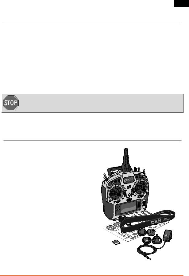
Box Contents
• DX9 Transmitter
• 2000mAh Li-Ion Transmitter Pack (Installed in transmitter)
• Global Power Supply
• SD card
• Neck strap
• Decal sheet
• Manual
SPEKTRUM DX9 • TRANSMITTER INSTRUCTION MANUAL |
3 |

EN
Table of Contents
Transmitter Batteries......................................................... |
5 |
Charging Your Transmitter................................................. |
5 |
Transmitter Functions........................................................ |
6 |
Main Screen........................................................................ |
8 |
Navigation.......................................................................... |
8 |
Auto Switch Select............................................................... |
8 |
SD Card............................................................................... |
9 |
Installing the SD Card.......................................................... |
9 |
Exporting the Transmitter Serial Number |
|
to the SD Card..................................................................... |
9 |
Power System Requirements............................................. |
9 |
Binding............................................................................. |
10 |
Binding Using the Receiver and Receiver Battery................. |
10 |
Binding Using the Receiver and ESC................................... |
10 |
Programming Failsafe Positions...................................... |
11 |
SmartSafeTM Failsafe.......................................................... |
11 |
Hold Last Command.......................................................... |
11 |
Preset Failsafe................................................................... |
11 |
Model Type Programming Guide..................................... |
12 |
Common System Setup FunctIons................................... |
13 |
Model Select..................................................................... |
13 |
Model Type........................................................................ |
13 |
Model Name...................................................................... |
13 |
F-Mode Setup................................................................... |
14 |
Aircraft and Sailplane Flight Mode Table.............................. |
14 |
Spoken Flight Mode Setup.................................................. |
14 |
Channel Assignment.......................................................... |
15 |
Channel Input Configuration............................................... |
15 |
Trim Setup........................................................................ |
15 |
Model Utilities................................................................... |
16 |
Create New Model............................................................. |
16 |
Delete Model..................................................................... |
16 |
Copy Model....................................................................... |
16 |
Model Reset...................................................................... |
16 |
Sort Model List.................................................................. |
16 |
Warnings.......................................................................... |
17 |
Telemetry.......................................................................... |
17 |
Telemetry Auto-Configuration............................................. |
17 |
Telemetry Alarms............................................................... |
18 |
Preflight Setup .................................................................. |
18 |
Frame Rate....................................................................... |
18 |
Bind.................................................................................. |
18 |
Trainer .............................................................................. |
19 |
Wired Trainer..................................................................... |
19 |
Wireless Trainer................................................................. |
20 |
System Settings............................................................... |
21 |
User Name........................................................................ |
21 |
Contrast............................................................................ |
21 |
Backlight........................................................................... |
21 |
Mode................................................................................ |
21 |
Battery Alarm.................................................................... |
21 |
Selecting a Language......................................................... |
22 |
Inactive Alarm.................................................................... |
22 |
Extra Settings.................................................................... |
22 |
System Sounds.................................................................. |
22 |
Vibrator............................................................................. |
22 |
Trim Display...................................................................... |
22 |
Serial Number................................................................... |
23 |
Calibrate........................................................................... |
23 |
Transfer SD Card.............................................................. |
24 |
Import Model..................................................................... |
24 |
Export Model..................................................................... |
24 |
Updating Spektrum DX9 Sound Files................................... |
24 |
Update AirWare Software.................................................... |
25 |
Servo Setup ..................................................................... |
25 |
Travel Adjust...................................................................... |
25 |
Sub-Trim........................................................................... |
25 |
Reverse............................................................................. |
25 |
Function List..................................................................... |
25 |
D/R & Exponential.............................................................. |
26 |
Speed............................................................................... |
26 |
Absolute (Abs.) Travel......................................................... |
26 |
Balance............................................................................. |
26 |
Differential (Air and Sail Types only)..................................... |
26 |
V-Tail Differential (Air and Sail Types only)........................... |
27 |
Throttle Cut....................................................................... |
27 |
Throttle Curve.................................................................... |
27 |
Mixing............................................................................... |
28 |
Offset................................................................................ |
28 |
Trim.................................................................................. |
28 |
Assigning a Mix to a Switch................................................ |
28 |
Back Mixing...................................................................... |
28 |
Sequencer......................................................................... |
29 |
Sequencer SetUp............................................................... |
29 |
System Sounds.................................................................. |
30 |
Range Test........................................................................ |
30 |
Timer................................................................................ |
30 |
Telemetry.......................................................................... |
30 |
System Setup.................................................................... |
31 |
Monitor............................................................................. |
31 |
ACRO (Airplane)................................................................ |
32 |
Recommended Servo Connections...................................... |
32 |
Elevon Servo Control.......................................................... |
33 |
Flap System...................................................................... |
33 |
ACRO Mixing..................................................................... |
33 |
Acro Gyro Function ........................................................... |
34 |
Pitch Curve Function.......................................................... |
34 |
Swash Type....................................................................... |
35 |
Collective Type................................................................... |
35 |
Pitch Curve....................................................................... |
35 |
HELI (Helicopter)............................................................... |
35 |
Swashplate....................................................................... |
36 |
Gyro.................................................................................. |
36 |
Governor........................................................................... |
36 |
Tail Curve ......................................................................... |
37 |
Mixing .............................................................................. |
37 |
SAIL (Sailplane)................................................................ |
38 |
Camber Preset.................................................................. |
38 |
Camber System................................................................. |
38 |
SAIL Mixing....................................................................... |
39 |
Physical Transmitter Adjustments.................................. |
40 |
Transmitter Mode Conversion ............................................ |
40 |
Mechanical Conversion...................................................... |
40 |
Adjust Throttle Friction Straps............................................. |
42 |
Adjusting the Throttle Ratchet Strap.................................... |
42 |
Control Stick Length Adjustment ........................................ |
42 |
Adjust Stick Tension .......................................................... |
42 |
Troubleshooting Guide..................................................... |
43 |
1-Year Limited Warranty.................................................. |
44 |
Warranty and Service Contact Information..................... |
45 |
FCC Information............................................................... |
45 |
Antenna Separation Distance.......................................... |
45 |
IC Information................................................................... |
45 |
FAA Information............................................................... |
45 |
Compliance Information for the European Union............ |
46 |
Declaration of Conformity................................................ |
46 |
Instructions for disposal of WEEE................................... |
46 |
Replacement Parts......................................................... |
223 |
4 |
SPEKTRUM DX9 • TRANSMITTER INSTRUCTION MANUAL |

EN
Transmitter Batteries
Battery and Charging Precautions and Warnings
Failure to exercise caution while using this product and comply with the following warnings could result in product malfunction, electrical issues, excessive heat, FIRE, and ultimately injury and property damage.
•Read all safety precautions and literature prior to use of this product
•Never allow minors to charge battery packs
•Never drop charger or batteries
•Never attempt to charge damaged batteries
•Never attempt to charge a battery pack containing different types of batteries
•Never charge a battery if the cable has been pinched or shorted
•Never allow batteries or battery packs to come into contact with moisture at any time
•Never charge batteries in extremely hot or cold places (recommended between 50–80 degrees F or 10–27 degrees C) or place in direct sunlight
•Always disconnect the battery after charging, and let the charger cool between charges
•Always inspect a new battery before charging
•Always terminate all processes and contact Horizon Hobby if the product malfunctions
•Always keep batteries and charger away from any material that could be affected by heat (such as ceramic and tile), as they can get hot
•Always end the charging process if the charger or battery becomes hot to the touch or starts to change form (swell) during the charge process
Charging Your Transmitter
The DX9 has an internal charger designed to charge the included 2-cell Li-Ion battery at a charge rate of 200mAh. The charge port on the right side of the transmitter is not polarity-dependent.
NOTICE: Never connect an external battery charger to your DX9 transmitter. If you wish to charge the Li-Ion battery using a Lipo/ Li-Ion charger, you must remove the battery from the transmitter before charging.
The first time you charge the transmitter battery, the charge time may be 12–15 hours. Always charge the transmitter on a heatresistant surface.
1.Power off your transmitter.
2.Connect the power supply connector to the transmitter charge port.

 CAUTION: Never leave a charging battery unattended.
LED indicators
The blue LED indicates the transmitter battery is charging. The orange LED indicates the transmitter is powered on and there is radio transmission.
Battery Alarm
The System Settings Screen allows you to change the battery type and low alarm settings. See “System Settings” for more information.
•An alarm will sound when the battery reaches the low voltage limit (4.3V for NiMH, 6.4V for LiPo/Li-Ion).
3.Connect the power supply to a power outlet using the appropriate adapter.
4.The blue LED on the front of the transmitter turns on during charging and turns off when the battery is fully charged.
5.Disconnect the transmitter from the power supply once charging is complete and disconnect the power supply from the power outlet.
CAUTION: Never change the low voltage limit for LiPo/Li-Ion batteries from 6.4V. Doing so could over-
discharge the battery and damage both battery and transmitter.
SPEKTRUM DX9 • TRANSMITTER INSTRUCTION MANUAL |
5 |

EN
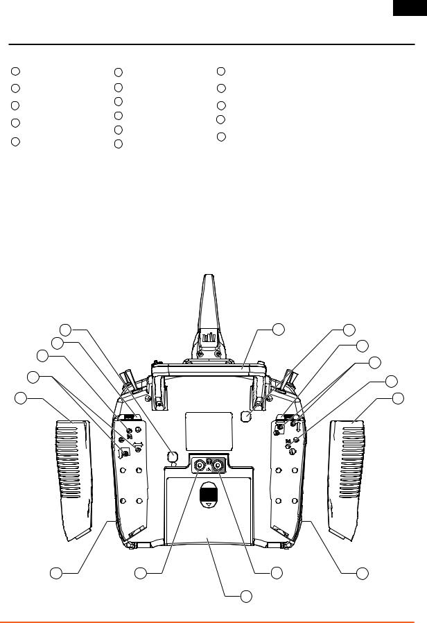
Transmitter Functions
Function |
|
Function |
|
Function |
|||
1 |
Antenna 1 |
|
9 |
Elevator Trim (Mode 2, 4) |
|
20 |
Rudder Trim (Mode 1,2) |
|
|
|
Throttle Trim (Mode 1, 3) |
|
Aileron Trim (Mode 3,4) |
||
2 |
Right Trim |
|
|
|
|
||
|
10 |
Aileron Trim (Mode 1,2) |
|
21 |
Elevator Trim (Mode 1,3) |
||
|
|
|
|
||||
3 |
Right Knob |
|
Rudder Trim (Mode 3,4) |
|
Throttle Trim (Mode 2,4) |
||
|
|
|
|
||||
|
|
|
11 |
Roller |
|
|
Elevator/Rudder Stick |
4 |
Switch E |
|
|
|
|||
|
|
|
|
|
|
|
(Mode 1) |
|
|
|
12 |
Charge Port |
|
|
|
|
|
|
|
|
|||
5 |
Switch H |
|
|
|
Throttle/Rudder Stick |
||
|
|
|
13 |
Speaker Grill |
|
22 |
(Mode 2) |
6 |
Switch G |
|
|
||||
|
|
Elevator/Aileron Stick |
|||||
|
|
|
14 |
On/Off Switch |
|
|
|
7 |
Switch F |
|
|
|
(Mode 3) |
||
|
|
|
|
|
|
|
Throttle/Aileron Stick |
|
|
|
15 |
LCD |
|
|
|
|
Throttle/Aileron Stick |
|
|
|
|||
|
|
|
|
(Mode 4) |
|||
|
(Mode 1) |
|
|
|
|
|
|
|
|
16 |
Clear Button |
|
|
|
|
|
|
|
|
|
|||
|
Elevator/Aileron Stick |
|
|
23 |
Switch C |
||
|
|
|
|
|
|||
8 |
(Mode 2) |
|
17 |
Back Button |
|
|
|
|
|
|
|
||||
Throttle/Rudder Stick |
|
|
|
|
24 |
Switch B |
|
|
|
18 |
SD Card Slot |
|
|||
|
(Mode 3) |
|
|
||||
|
|
|
|
|
|||
|
|
|
|
|
|
|
|
|
Elevator/Rudder Stick |
|
|
|
|
25 |
Switch A |
|
|
19 |
Neck Strap Mount |
|
|||
|
(Mode 4) |
|
|
||||
|
|
|
|
|
|
|
|
Function
26Switch D
27Bind/Switch I
28Left Trim
29LED
The transmitter comes with a thin, clear plastic film applied to some front panels for protection during shipping. Humidity and use may cause this film to come off. Carefully remove this film as desired.
|
|
|
1 |
|
|
|
28 |
|
2 |
|
27 |
29 |
|
3 |
|
|
|
||
|
26 |
|
|
4 |
24 |
25 |
|
|
5 |
|
|
|
6 |
|
23 |
|
|
|
7 |
22 |
|
|
|
8 |
21 |
|
|
|
9 |
|
|
|
|
|
20 |
|
|
|
10 |
|
CLEAR |
|
|
|
|
|
|
|
|
|
|
BACK |
|
11 |
19 |
|
® |
|
|
|
|
|
|
|
|
|
|
™ |
|
18 |
|
|
|
12 |
|
|
16 |
|
13 |
|
|
17 |
15 |
14 |
6 |
SPEKTRUM DX9 • TRANSMITTER INSTRUCTION MANUAL |
EN
Transmitter Functions
|
Function |
|
|
Function |
|
|
Function |
1 |
Handle/Antenna 2 |
|
6 |
Left Rear Grip |
|
12 |
Right Rear Grip |
|
|
|
|
|
|
|
|
|
Throttle Spring Tension |
|
|
|
|
|
Gimbal Stick Tension |
2 |
|
7 |
SD Card |
|
13 |
||
Adjustment (Mode 2,4) |
|
|
Adjustment |
||||
|
|
|
|
|
|
||
|
|
8 |
Audio Jack |
|
|
||
3 |
Left Lever |
|
|
14 |
Mode Change |
||
|
|
|
|
||||
|
|
|
9 |
Battery Cover |
|
|
|
4 |
Gimbal Stick Tension |
|
15 |
Right Lever |
|||
|
|
|
|
||||
Adjustment |
|
10 |
Trainer Port |
|
|
|
|
|
|
|
16 |
Throttle Spring Tension |
|||
|
|
|
|
|
|
||
5 |
Mode Change |
|
11 |
Charge Port |
|
Adjustment (Mode 1,3) |
|
|
|
|
|||||
|
|
|
|
|
|
|
|
16 |
1 |
2 |
15 |
|
3 |
14 |
|
|
|
4 |
|
|
|
|
13 |
|
5 |
|
|
|
12 |
|
6 |
11 |
10 |
8 |
7 |
9
SPEKTRUM DX9 • TRANSMITTER INSTRUCTION MANUAL |
7 |
EN
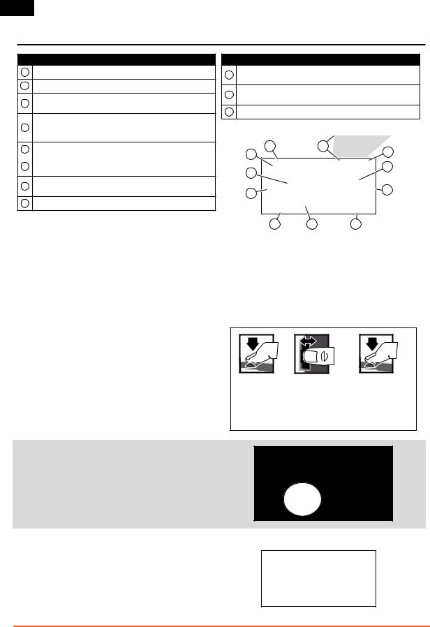
Main Screen
Function
AModel Name
BDSMX/DSM2 If not shown, this indicates “not bound”.
C |
Transmitter Battery |
Also displays the Volume Level |
Charge Level |
when the BACK button is pressed |
Digital Battery Voltage (an alarm sounds and the screen flashes
Dwhen battery charge gets down to 4.3V when using an NiMH battery or 6.4V for a LiPo/Li Ion battery.)
EModel Type
F |
Elevator Trim (Modes 2 and 4) |
Also displays R Trim values when |
|
Throttle Trim (Modes 1 and 3) |
the Right Trim button is pressed |
||
|
GAileron Trim (Modes 1 and 2) Rudder Trim (Modes 3 and 4)
HModel Memory Timer
Function
I |
Rudder Trim (Modes 1 and 2) |
Also displays L Trim values when |
|
Aileron Trim (Modes 3 and 4) |
the Left Trim button is pressed |
||
|
JThrottle Trim (Mode 2 and 4) Elevator Trim (Mode 1 and 3)
KTimer
B |
C |
D |
A |
|
|
|
|
|
K |
|
E |
|
|
J |
F |
|
Navigation |
I |
H |
G |
|
|
|
|
|
|
||
• Turn the scroll wheel to move through the screen content or |
• At the main screen you can roll the roller to view the servo |
||
change programming values. Press the scroll wheel to make |
monitor. |
|
|
a selection. |
• The Main Screen appears when you power on the transmitter. |
||
• Use the Back button to go to the previous screen |
Press the scroll wheel once to display the Function List. |
||
(for example, to go from the Mixing Screen to the Function |
• When you want to change a value in a screen for a particular |
||
List). |
control position, move the control to the desired position to |
||
• Use the Clear button to return a selected value on a screen to |
highlight the value you want to change, such as 0/1/2, up/ |
||
the default setting. |
down or left/right. |
|
|
•Direct Model Access enables you to access the Model Select screen without powering off the transmitter. Anytime the transmitter power is on, press the Clear and Back buttons to access the Model Select screen.
•Press and hold the roller while powering on the transmitter to show the System Setup list. No radio transmission occurs when a System Setup screen is displayed, preventing accidental damage to linkages and servos during changes to programming.
Press |
Enter, Choose or Exit
Turn |
Move between options or change value in an option
Hold |
Hold for 3 seconds and release to move to the Main Screen
Tip: The tick mark below shows the current switch position.
Rolling and clicking the roller turns the selected box black, indicating that the value or condition will act on that position.
Auto Switch Select
To easily select a switch in a function, such as a program mix, roll with the roller to highlight the switch selection box, and press the roller. The box around the switch should now flash. To select a switch, toggle the switch you wish to select. Verify the switch selection is now displayed as desired. When correct, press the roller to select this switch and complete the switch selection.
8 |
SPEKTRUM DX9 • TRANSMITTER INSTRUCTION MANUAL |
EN
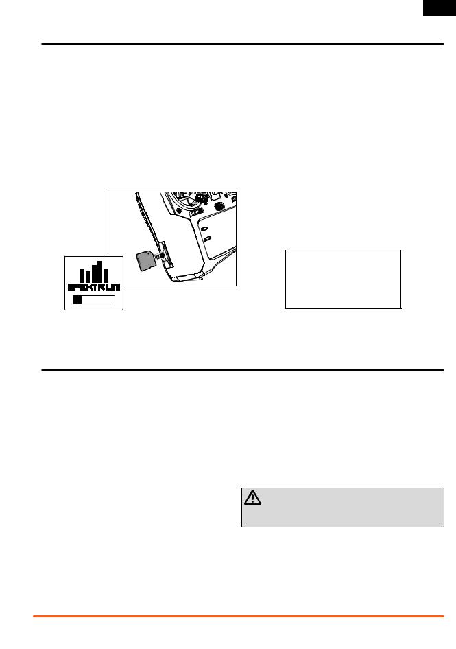
SD Card
Installing the SD Card
The included SD Card enables you to:
•Import (copy) models from another DX9 transmitter
•Export (transfer) models to another
DX9 transmitter
•Update AirWare™ software in the transmitter
•Install/Update sound files
To install the SD Card:
1.Power off the transmitter.
2.Press the SD Card into the card slot with the card label facing upward.
Exporting the Transmitter Serial Number to the SD Card
Exporting the transmitter serial number to the SD Card allows you to copy and paste the serial number into the registration screen at spektrumrc.com.
To export the serial number:
1.Press and hold the scroll wheel while powering the transmitter on until the System Setup list appears.
2.Scroll to the System Settings menu. Press the scroll wheel once to open the menu.
3.Select NEXT on the System Settings and Extra Settings screens.
4.When the Serial Number screen appears, select EXPORT.
5.Power off the transmitter and remove the SD Card from the transmitter.
6.Insert the SD Card in your computer and open the My_DX9.xml file on the card.
7.Import My_DX9.xml into the Registration screen on the Spektrum Community site (spektrumrc.com).
Power System Requirements
Inadequate power systems that do not provide the necessary minimum voltage to the receiver during flight are the number one cause of in-flight failures. Some of the power system components that affect the ability to properly deliver adequate power include:
•Receiver battery pack (number of cells, capacity, cell type, state of charge)
•The ESC’s capability to deliver current to the receiver in electric aircraft
•The switch harness, battery leads, servo leads, regulators, etc.
Recommended Power System Test Guidelines
If a questionable power system is being used (e.g., a small or old battery, an ESC that may not have a BEC that will support highcurrent draw, etc.), perform the following test with a voltmeter.
The Hangar 9 ® Digital Servo & Rx Current Meter (HAN172) or the
Spektrum Flight Log (SPM9540) work well for this test.
Plug the voltmeter into an open channel port in the receiver and, with the system on, load the control surfaces (apply pressure with your hand) while monitoring the voltage at the receiver. The voltage should remain above 4.8 volts even when all servos are heavily loaded.
CAUTION: When charging Ni-MH batteries, make sure the battery fully charges. Ni-MH batteries charged with peak
detection fast chargers have a tendency to false peak (i.e. not fully charge), which could lead to a crash.
SPEKTRUM DX9 • TRANSMITTER INSTRUCTION MANUAL |
9 |
EN
Binding
Binding is the process of programming the receiver to recognize the GUID (Globally Unique Identifier) code of a single specific transmitter. You will need to rebind after the model programming is initially set up to fully program the model’s failsafe positions.
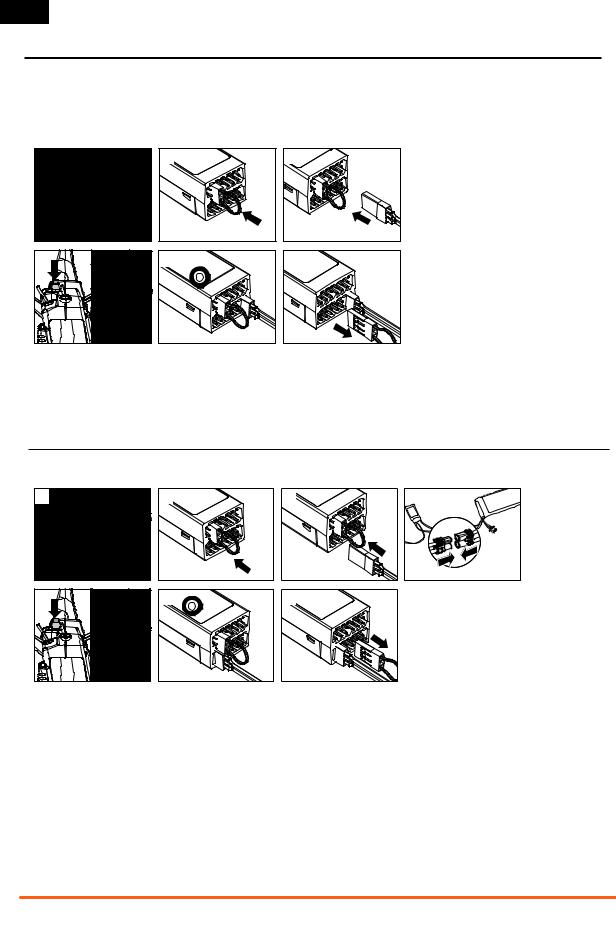
Binding Using the Receiver and Receiver Battery
1. |
4. |
2. |
5. |
3. |
6. |
1.Lower throttle to the lowest position and make sure the transmitter is powered off.
2.Insert the bind plug into the BIND/DATA port.
3.Insert the receiver battery into any open port. The receiver’s
LED will flash when the receiver is ready to bind.
4.While pressing the Bind button, power on the transmitter.
5.Release the Bind button after the receiver has stopped flashing rapidly, once the receiver’s LED stays illuminated; this indicates the receiver is bound to the transmitter. The screen also provides binding information.
6.Remove the bind plug from the receiver.
Binding Using the Receiver and ESC
1. |
5. |
2. |
3. |
4. |
6. |
7. |
|
1.Lower throttle to the lowest position and make sure the transmitter is powered off.
2.Insert the bind plug into the BIND/DATA port.
3.Insert the ESC plug into the THRO port.
4.Connect battery to ESC and turn on ESC switch, if available. The receiver’s LED will rapidly flash when the receiver is ready to bind.
5.While pressing the Bind button, power on the transmitter.
6.Release the Bind button after the receiver has stopped flashing rapidly, once the receiver’s LED stays illuminated; this indicates the receiver is bound to the transmitter. The screen also provides binding information.
7.Remove the bind plug from the receiver.
10 |
SPEKTRUM DX9 • TRANSMITTER INSTRUCTION MANUAL |
EN
Programming Failsafe Positions
You establish failsafe positions when you bind your transmitter and receiver. If the radio signal connection is lost between the transmitter and receiver, the receiver immediately moves the aircraft control surfaces to the failsafe positions. If you assign the receiver THRO channel to a transmitter channel other than throttle, we recommend using Preset failsafe with the throttle in the low position.
SmartSafeTM Failsafe
SmartSafe failsafe is a technology that only acts on the throttle channel and offers the following benefits:
•Prevents electric motors from operating when the receiver power is on and the transmitter power is off.
•Prevents the speed controller from arming until the throttle is moved to the low throttle position.
•Powers off an electric motor and reduces gas/glow engines to idle if signal is lost.
Hold Last Command
The Hold Last Command failsafe maintains the last command on all channels except throttle. If the radio signal is lost, the aircraft maintains the commanded heading until the receiver regains signal.
To program Hold Last Command, follow the provided binding instructions in this instruction manual.
To Test Hold Last Command:
1.Power on the transmitter and receiver.
2.Move one of the control sticks to the desired Hold Last
Command position and hold the input.
3.While holding the control input (for example, a small amount of rudder) power off the transmitter. The rudder should maintain the input command.
Preset Failsafe
The Preset failsafe moves all channels to their programmed failsafe positions.
We recommend using Preset failsafe to deploy spoilers on sailplanes to prevent a flyaway if the radio signal is lost.
To program Preset failsafe:
1.Insert the bind plug in the bind port on the receiver and power on the receiver.
2.Remove the bind plug when the orange LED on the main receiver and all attached remote receivers flash rapidly. The orange receiver LEDs will continue flashing.
NOTICE: Failsafe features vary according to receiver. Always consult the receiver instruction manual for failsafe features.
Before flight, ALWAYS confirm the failsafe functions as you would expect.
To Program SmartSafe, move the throttle to the low or off position before putting the transmitter into bind mode.
To Test the SmartSafe failsafe
1.Power the transmitter and receiver on.
2.Power off the transmitter. The throttle should immediately move to the failsafe position.
CAUTION: Make sure the aircraft is fully restrained on the ground. If the failsafe is not set correctly, your aircraft might
advance to mid or full throttle.
CAUTION: Make sure the aircraft is fully restrained on the ground. If the failsafe is not set correctly, the aircraft throttle
might advance to mid or full throttle.
3.Move the transmitter control sticks and switches to the desired Preset failsafe position. Power the transmitter on.
4.Failsafe programming is complete when the orange LEDs on the transmitter and all receivers turn solid.
CAUTION: Make sure the aircraft is fully restrained on the ground. If the failsafe is not set correctly, the aircraft throttle
might advance to mid or full throttle.
SPEKTRUM DX9 • TRANSMITTER INSTRUCTION MANUAL |
11 |

EN
Model Type Programming Guide
Menu options show up on model type selection. These menu options vary between Model Types (Airplane, Helicopter and Sailplane), but are identical for all models in that type. Subsequent aircraft type (Aircraft, Swashplate or Sailplane) selections make other menu options appear.
System Setup List: |
Function List: |
System Setup List: |
Function List: |
Model Select |
Servo Setup |
Model Select |
Servo Setup |
Model Type |
D/R and Expo |
Model Type |
D/R and Expo |
Model Name |
Differential |
Model Name |
Differential |
Aircraft Type |
V-Tail Differential |
Sailplane Type |
V-Tail Differential |
F-Mode Setup |
Throttle Cut |
F-Mode Setup |
Throttle Cut |
Spoken Flight Mode |
Throttle Curve |
Spoken Flight Mode |
Motor Curve |
Channel Assign |
Gyro1 |
Channel Assign |
Camber Presets |
Trim Setup |
Gyro2 |
Trim Setup |
Camber System |
Model Utilities |
Gyro3 |
Model Utilities |
Mixing |
Warnings |
Pitch Curve |
Warnings |
Sequencer |
Telemetry |
Flap System |
Telemetry |
Range Test |
Preflight Setup |
Mixing |
Preflight Setup |
Timer |
Frame Rate |
Sequencer |
Frame Rate |
Telemetry |
Bind |
Range Test |
Bind |
Custom Voice Setup |
Trainer |
Timer |
Trainer |
System Setup |
System Settings |
Telemetry |
System Settings |
Monitor |
Transfer SD Card |
Custom Voice Setup |
Transfer SD Card |
|
|
System Setup |
|
|
Monitor
System Setup List: |
Function List: |
Model Select |
Servo Setup |
Model Type |
D/R and Expo |
Model Name |
Throttle Cut |
Swashplate Type |
Throttle Curve |
F-Mode Setup |
Pitch Curve |
Spoken Flight Mode |
Swashplate |
Channel Assign |
Gyro |
Trim Setup |
Governor |
Model Utilities |
Tail Curve |
Warnings |
Mixing |
Telemetry |
Sequencer |
Preflight Setup |
Range Test |
Frame Rate |
Timer |
Bind |
Telemetry |
Trainer |
Custom Voice Setup |
System Settings |
System Setup |
Transfer SD Card |
Monitor |
12 |
SPEKTRUM DX9 • TRANSMITTER INSTRUCTION MANUAL |

EN
Common System Setup FunctIons
Model Select
Model Select enables you to access any of the 250 internal model memory locations in the Model Select list.
1.Scroll to the desired model memory in the Model Select list.
2.When the desired model memory is highlighted, press the scroll wheel once to select the model. The transmitter returns to the System Setup List.
3.Add a new model by rolling to the bottom of the list. You will then be prompted with the Create New Model screen, with the option to create a new model or cancel. If you select
Cancel the system will return to the Model Select function. If you select Create, the new model will be created and now be available in the model select list.
Direct Model Access
Press the Clear and Back buttons from the Main Screen or a telemetry screen to access Model Select.
Model Type
Select from Airplane, Helicopter or Sailplane model types.
IMPORTANT: When you select a new model type, you will delete any programming data in the current model memory. Always confirm the desired model memory before changing model types. It will be necessary to re-bind after resetting the model type.
To change the model type:
1.Scroll to the desired model type and press the scroll wheel.
The Confirm Model Type screen appears.
2.Select Yes and press the scroll wheel to confirm the model type. All data will be reset. Selecting No will exit the Confirm
Model Type screen and return to the Model Type screen.
Model Name
Model Name enables you to assign a custom name to the current model memory. Model names can include up to 20 characters including spaces.
To add letters to a Model Name:
1.Scroll to the desired letter position and press the scroll wheel once. A flashing box appears.
2.Scroll left or right until the desired character appears. Press the scroll wheel once to save the character.
3.Scroll to the next desired letter position. Repeat Steps 1 and 2 until the Model Name is complete.
4.Select BACK to return to the System Setup list.
To erase a character:
1.Press CLEAR while the character is selected.
2.Press CLEAR a second time to erase all characters to the right of the cursor.
SPEKTRUM DX9 • TRANSMITTER INSTRUCTION MANUAL |
13 |

EN
F-Mode Setup
Use the Flight Mode Setup menu to assign switches to flight modes.
Mode |
Number of Switches |
Number of Flight Modes |
||
|
|
|
|
|
Aircraft |
2 |
5 |
|
|
|
|
|
|
|
Heli |
3 (including Throttle Hold) |
5 (including Throttle Hold) |
||
|
|
|
|
|
|
|
|
|
|
|
|
|
|
|
Sailplane Flight Mode Setup
You can assign up to ten flight modes using any combination of up to three switches. You can also assign a priority switch. When the priority switch position is active, only the current flight mode is active, regardless of other switch positions.
Aircraft and Sailplane Flight Mode Table
You can assign the available flight modes (up to 5 for Air, up to 10 for Sail) to each of the switch positions (up to 3 switches can be used for sailplane and up to 2 switches can be used for aircraft). Press NEXT from the Flight Mode Name page to access the flight mode table assignment page when Custom flight mode has been selected in the
Flight Mode Setup page. The combination of up to 2 or 3 switches can be used to access all of the flight modes available.
Number |
|
|
|
|
|
|
of Flight |
2 |
3 |
3* |
4 |
4 |
5 |
Modes |
|
|
|
|
|
|
Switch 1 |
|
|
|
|
|
|
(number of |
2P |
3P |
2P |
2P |
3P |
3P |
positions) |
|
|
|
|
|
|
|
|
|
|
|
|
|
Switch 2 |
|
|
|
|
|
|
(number of |
|
|
2P |
3P |
2P |
3P |
positions) |
|
|
|
|
|
|
Flight |
|
|
|
|
|
|
Mode |
Launch |
Launch |
Launch |
Launch |
Launch |
Launch |
1 |
|
|
|
|
|
|
|
|
|
|
|
|
|
2 |
Cruise |
Cruise |
Cruise |
Cruise |
Cruise |
Cruise |
|
|
|
|
|
|
|
3 |
|
Land |
|
|
Land |
Land |
4 |
|
|
Thermal |
Thermal |
Thermal |
Thermal |
|
|
|
|
|
|
|
5 |
|
|
|
Speed |
|
Speed |
*Must be set up in a 4/5 flight mode.
Spoken Flight Mode Setup
Enables you to assign custom names to the Flight Mode positions. Flight Mode names can include up to 20 characters including spaces.
To change the Flight Mode name:
1.Scroll to the Flight Mode name you wish to change and press the scroll wheel.
2.Scroll to the character position you wish to change and press the scroll wheel once. A flashing box appears.
3.Scroll left or right until the desired character appears. Press the scroll wheel once to save the character.
4.Repeat Steps 2 and 3 until the Model Name is complete.
5.Select BACK to return to the Flight Mode Names list.
Spoken Flight Mode:
The Spoken Flight Mode option enables you to activate audio flight mode alerts. As you change between flight modes, the transmitter will “speak”, informing you of the active flight mode. You can select a word or phrase for each flight mode.
To activate Spoken Flight Mode:
1.Enter the Spoken Flight Mode menu option.
2.Scroll to <Silence> (default), then press the scroll wheel.
3.Scroll left or right to view the options.
4.Press the scroll wheel again to save the selection.
14 |
SPEKTRUM DX9 • TRANSMITTER INSTRUCTION MANUAL |

EN
Channel Assignment
The Channel Assignment function allows you to reassign almost any receiver channel to a different transmitter channel. For example, the receiver gear channel could be re-assigned to the transmitter throttle channel.
1.Scroll to the receiver channel you wish to change.
2.Press the scroll wheel once and scroll left or right to change the receiver input selection.
3.Press the scroll wheel a second time to save the selection.
IMPORTANT: You cannot assign a mix to a channel that has been moved. Create the mix first, then move the channel.
Channel Input Configuration
The Channel Input Configuration screen enables you to assign a transmitter channel to a different control stick
or switch.
1.Select NEXT on the RX Port Assignments screen to access the
Channel Input Configuration screen.
2.Scroll to the transmitter channel you wish to re-assign and press the scroll wheel. The box around the current input selection flashes.
3.Scroll left or right to select the desired control stick or switch.
4.Press the scroll wheel to save the selection.
Trim Setup
Use the Trim Setup screen to change the size of the trim step and the trim type.
Trim Step
Adjusting the trim step value determines how many “clicks” of trim you input each time you press the trim button. Changing the trim step value to 0 disables the trim for the channel.
To change the trim step value:
1.Scroll to the trim step channel you wish to change.
2.Select the trim step value and scroll left or right to change the value.
3.Press the scroll wheel to save the selection.
Trim Type
The two Trim Type options are Common and F Mode.
Common trim type maintains the same trim values for all flight modes.
F Mode trim type enables you to save trim values for individual flight modes if you find, for example, the aircraft requires aileron trim in Flight Mode 1 but not in Flight Mode 2.
Trim Assignment
In a few instances, you can reassign a trim to a different location.
Aircraft Model Type
Throttle
•Throttle Digital trim button (default)
•Left Analog lever
•Right Analog lever
Throttle Trim Type
•Common
•Flight Mode
Helicopter Model Type
Throttle and Pitch Hover Trim — Used to trim the throttle and pitch setting for precision hovering. This does not affect normal throttle trim operation.
•Right Knob
•Left Analog Lever
•Right Analog Lever
•L Trim
•R Trim
Active Gyro and Governor Trim— Used to trim the gyro and governor settings in flight.
•L Trim
•R Trim.
Trim Location
Normal and Cross trim types are available. Normal trims align with the control stick; for example, the throttle trim is next to the throttle stick.
Cross trims reverse the position of the trims; for example, the throttle trim is next to the elevator stick and vice versa.
To change the Trim Position from Normal to Crossed, select Normal at the bottom of the Trim Setup screen and press the scroll wheel.
IMPORTANT: Crossed trims will cross both sets of trims for both gimbals.
SPEKTRUM DX9 • TRANSMITTER INSTRUCTION MANUAL |
15 |
 Loading...