


SPM4200 DX4C

Instruction Manual
Bedienungsanleitung
Manuel d’utilisation
Manuale di istruzioni
DX4C DX4C
4-Channel 2.4GHz DSMR™ System4-Channel 2.4GHz DSMR™ System
SPEKTRUM DX4C • TRANSMITTER INSTRUCTION MANUAL
EN
WARNING: Read the ENTIRE instruction manual to become familiar with the features of the product before operating.
Failure to operate the product correctly can result in damage to the product, personal property and cause serious injury.
This is a sophisticated hobby product. It must be operated with caution and common sense and requires some basic mechanical
ability. Failure to operate this product in a safe and responsible manner could result in injury or damage to the product or other
property. This product is not intended for use by children without direct adult supervision. Do not attempt disassembly, use with
incompatible components or augment product in any way without the approval of Horizon Hobby, LLC. This manual contains
instructions for safety, operation and maintenance. It is essential to read and follow all the instructions and warnings in
the manual, prior to assembly, setup or use, in order to operate correctly and avoid damage or serious injury.
WARNING AGAINST COUNTERFEIT PRODUCTS
Always purchase from a Horizon Hobby, LLC authorized dealer to ensure authentic high-quality Spektrum product. Horizon Hobby,
LLC disclaims all support and warranty with regards, but not limited to, compatibility and performance of counterfeit products
or products claiming compatibility with DSM or Spektrum.
Age Recommendation: Not for Children under 14 years. This is not a toy.
WARRANTY REGISTRATION
Visit community.spektrumrc.com today to register your product.
SAFETY PRECAUTIONS
• Always ensure all batteries have been properly charged
prior to using the model.
• Always check all servos and their connections prior
to each run.
• Never operate your model near spectators, parking areas
or any other area that could result in injury to people or
damage of property.
• Never operate your model during adverse weather
conditions. Poor visibility can cause disorientation
and loss of control of your model.
• Never point the transmitter antenna directly toward
the model. The radiation pattern from the tip of the
antenna is inherently low.
• If at any time during the operation of your model you
observe any erratic or abnormal operation, immediately
stop operation of your model until the cause of the
problem has been ascertained and corrected.
NOTICE
All instructions, warranties and other collateral documents are subject to change at the sole discretion of Horizon Hobby, LLC.
For up-to-date product literature, visit horizonhobby.com and click on the support tab for this Product.
MEANING OF SPECIAL LANGUAGE
The following terms are used throughout the product literature to indicate various levels of potential harm
when operating this product:
NOTICE: Procedures, which if not properly followed, create a possibility of physical property damage AND little
or no possibility of injury.
CAUTION: Procedures, which if not properly followed, create the probability of physical property damage AND
a possibility of serious injury.
WARNING: Procedures, which if not properly followed, create the probability of property damage, collateral
damage and serious injury OR create a high probability of superfi cial injury.
NOTICE: This product is only intended for use with unmanned, hobby-grade, remote-controlled vehicles and aircraft.
Horizon Hobby disclaims all liability outside of the intended purpose and will not provide warranty service related thereto.
3
SPEKTRUM DX4C • TRANSMITTER INSTRUCTION MANUAL
EN
TABLE OF CONTENTS
CONTENTS SYSTEM FEATURES
Identifying Controls and Switches ..................................4
Installing Batteries ........................................................4
the Rubber Grip ...........................................................5
Raceware Firmware Updates ........................................5
ModelMatch ................................................................5
Warning screens ..........................................................6
Receiver Compatibility ..................................................6
AVC – Active Vehicle Control ........................................6
Aux channels ...............................................................6
Electric Vehicle Installation ............................................7
Nitro Vehicle Installation ................................................7
SRS410 Failsafe ..........................................................7
SRS4210 Failsafe ........................................................7
Binding the Transmitter and Receiver ............................8
Main Screen ................................................................8
Using the Rolling Selector .............................................9
Individual Direction Adjustments ....................................9
List .............................................................................9
Press ..........................................................................9
Roll .............................................................................9
Hold ............................................................................9
Model........................................................................10
Reverse .....................................................................10
Travel ........................................................................10
Expo .........................................................................11
Sub-Trim ...................................................................12
Timer .......................................................................12
Name ........................................................................12
Switch .......................................................................13
System .....................................................................14
Copy .........................................................................14
Reset ........................................................................15
Active Vehicle Control (AVC) ........................................15
Mixing .......................................................................16
Steer Mix ...................................................................16
About ........................................................................17
Troubleshooting Guide ................................................17
1-Year Limited warranty .............................................18
WARRANTY SERVICES ................................................18
FCC Information .........................................................19
Antenna Separation Distance ......................................19
IC Information ............................................................20
Compliance Information for the European Union ...........20
Declaration of Conformity ...........................................20
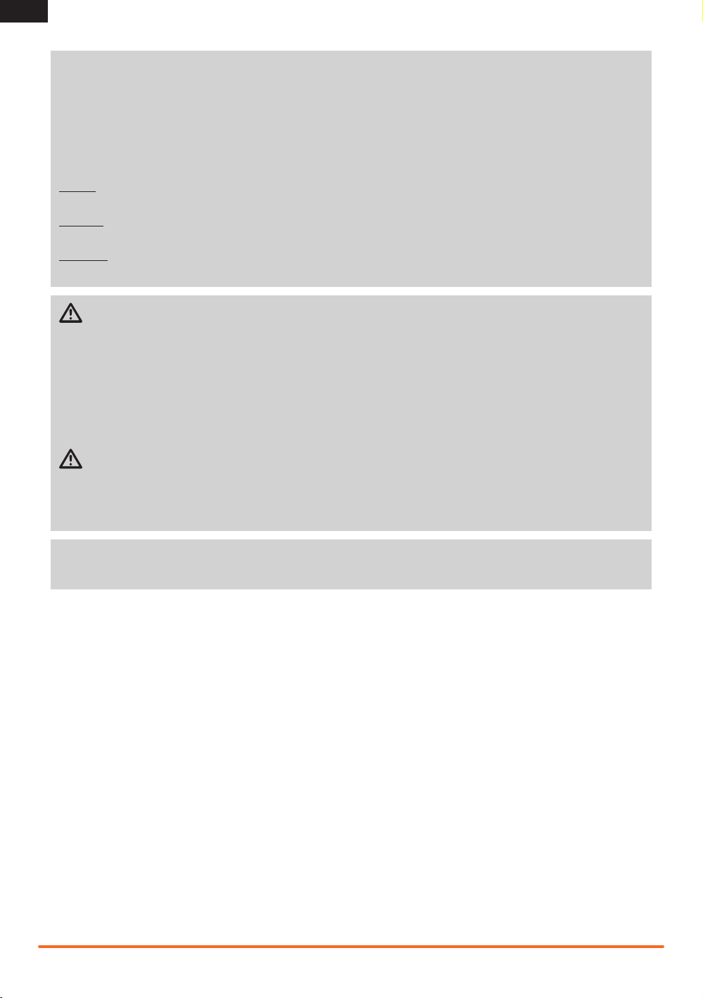
The DX4C radio system is supplied with the following:
• DX4C Transmitter
• SRS4210 Receiver (SPMSRS4210)
• Bind Plug (SPM6802)
• Grip Set (SPM9006)
• One-touch easy-to-use programming
• Programmable Up or Down timers
• 56 (high) x 64 (wide) high-resolution dot-matrix screen
• 20-model memory
• Travel adjust
• Exponential
• Steering mix
• Programmable mix
• AVC – Active Vehicle Control
SPEKTRUM DX4C • TRANSMITTER INSTRUCTION MANUAL
EN
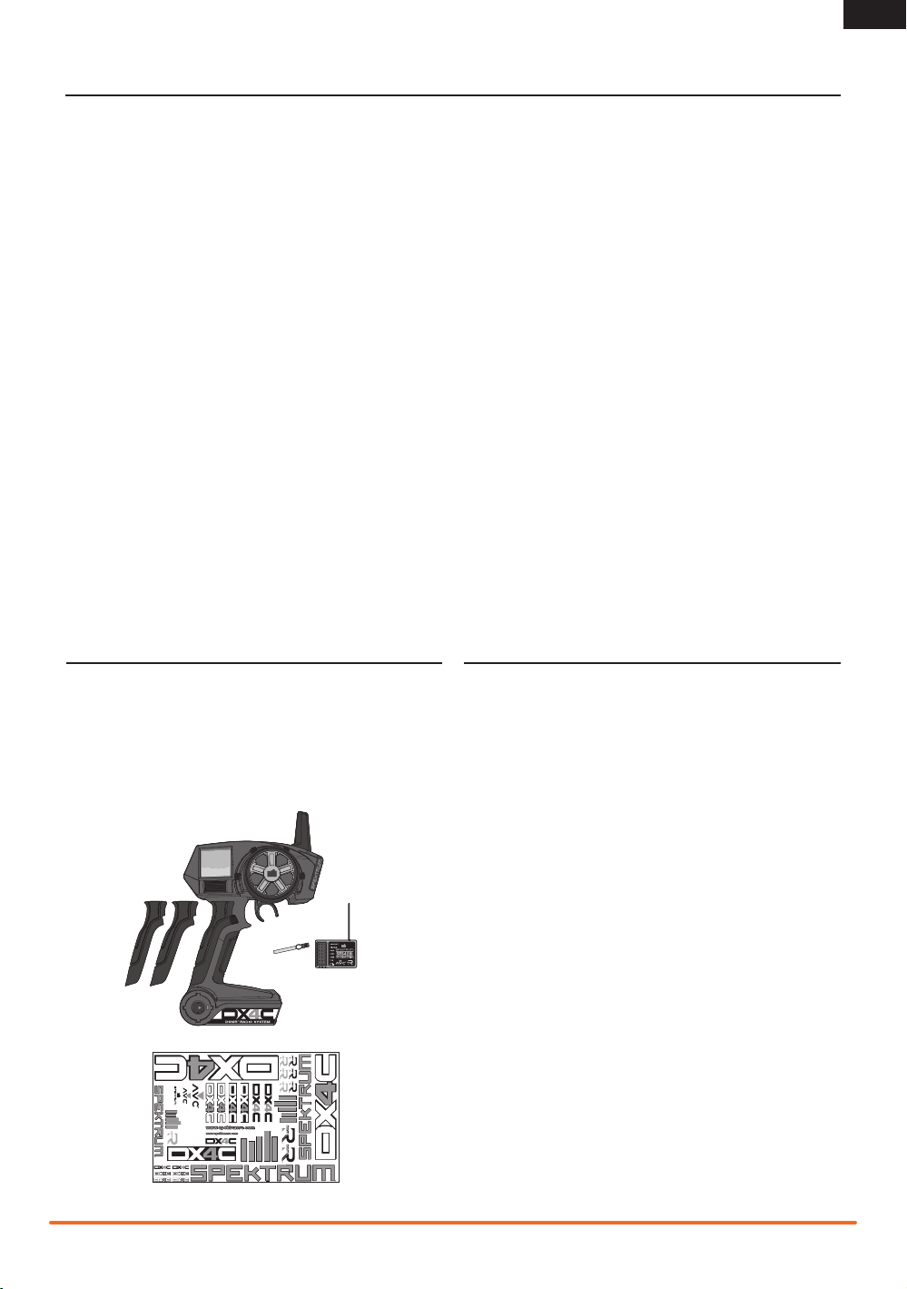
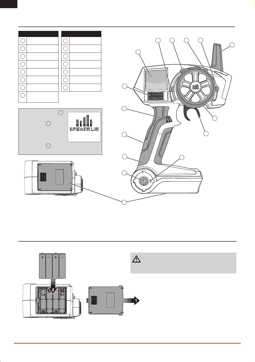
INSTALLING BATTERIES
CAUTION: NEVER remove the transmitter batteries
while the model is powered on. Loss of model control,
damage or injury may occur.
IDENTIFYING CONTROLS AND SWITCHES
Function
A
Button A
B
Button B
C
Button C
D
Button D
E
Button E
F
LCD Screen
G
Roller Selector
H
Memory Card Port
(under rubber grip)
Function
I
Rubber Grip
J
Power Switch
K
Power LED
L
Battery Cover
M
Throttle Trigger
N
Steering Wheel
O
Antenna
O
N
M
J
I
H
G
F
E
DCBA
L
Press the power switch to
power ON the transmitter.
The Power LED will
come on, a Spektrum logo
screen will show, then the
Main Screen will show on
the LCD screen .
K
K
F
J
5
SPEKTRUM DX4C • TRANSMITTER INSTRUCTION MANUAL
EN
THE RUBBER GRIP
This transmitter includes 3 sizes of grips. The medium-size grip
is installed at the factory.
To change the rubber grip
1. Lift the edge of the grip and pull the grip away from the
handle.
2. Align the tabs on the new grip with the slots in the handle.
3. Press the grip against the handle.
MODELMATCH
The Spektrum DX4C transmitter features ModelMatch™
technology, preventing you from operating a vehicle when the
wrong model memory is active in the transmitter. If you select
the wrong model memory, the receiver will not respond to
the transmitter.
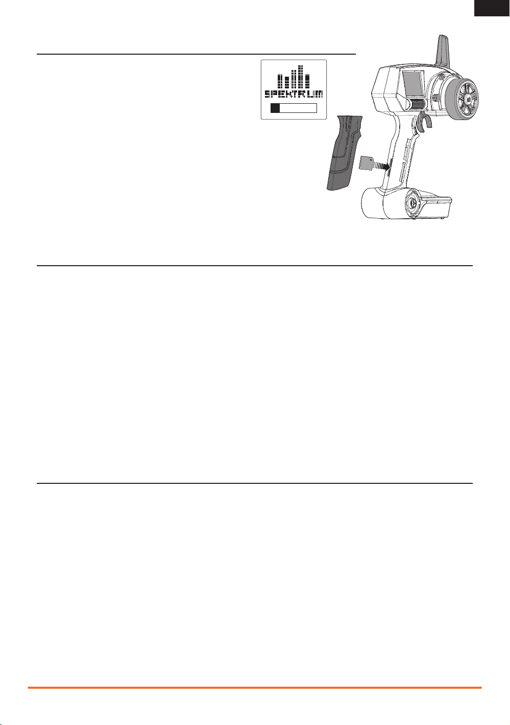
1. Remove the grip from the back of the transmitter handle.
2. Download the latest RaceWare fi rmware from
www.SpektrumRC.com to an SD card. The transmitter serial
number can be found by going to the About screen.
3. Install the SD card in the card reader slot on the DX4C
transmitter.
4. Power on the transmitter. A Spektrum logo and an installation
bar will appear. Installation is complete when the Main screen
appears.
5. Power off the transmitter.
6. Remove the SD card from the card slot on the transmitter.
7. Re-install the rubber grip on the transmitter handle.
The DX4C features an SD card reader, enabling you to update
the transmitter when RaceWare™ fi rmware updates are
available. Register your transmitter at www.SpektrumRC.com
to receive the latest information regarding RaceWare fi rmware
updates. To install RaceWare fi rmware updates on your DX4C
transmitter:
RACEWARE FIRMWARE UPDATES

SPEKTRUM DX4C • TRANSMITTER INSTRUCTION MANUAL
EN
RECEIVER COMPATIBILITY
WARNING SCREENS
Low Battery Alarm
An alarm will sound and a warning screen will show when the transmitter’s battery power
goes below a set limit. This alarm reminds a user to bring the model under full control, power
off the transmitter and replace batteries. Press the Roller to stop the alarm and go to the Main
Screen.
Set the low battery limit using the System Screen.
Inactivity Alarm
An alarm will sound and a warning screen will show when the transmitter has been left on
(approximately 10 minutes) without control movement. Moving any control will stop the alarm.
This alarm reminds users to power off the transmitter and save battery power.
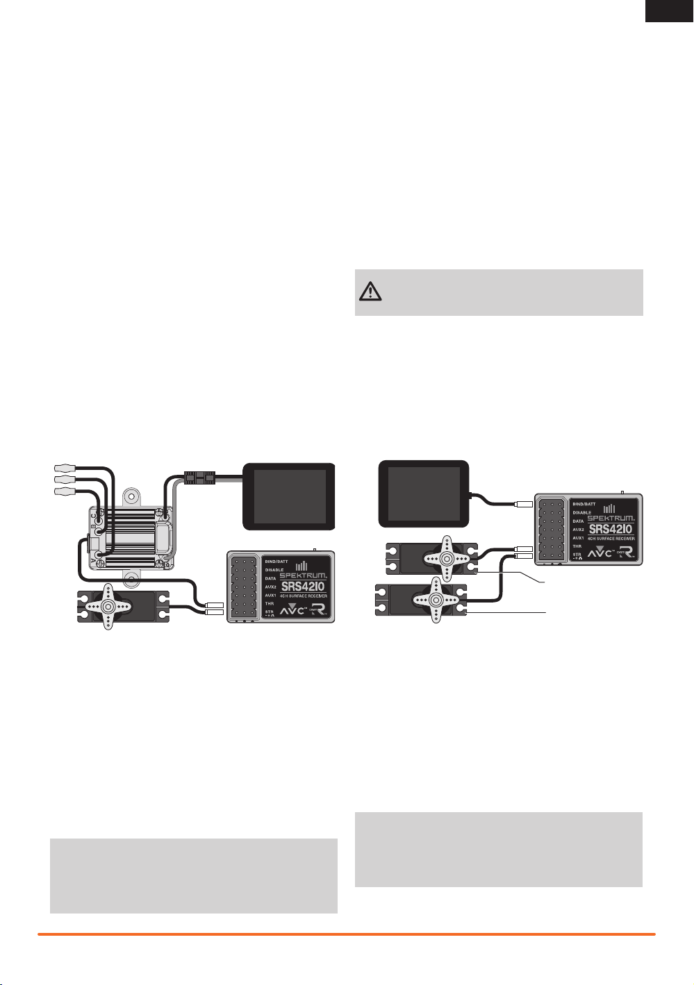
Aux 1 Port
Aux 2 Port
Antenna
Disable
Data
Bind/Battery Port
Steering Port
Throttle Port
AVC – ACTIVE VEHICLE CONTROL
The Spektrum SRS4210 receiver features Active Vehicle
Control™ (AVC™) technology that responds similar to traction
control in full-scale vehicles. In addition to traction control, AVC
technology also increases steering stability during high speed
driving or while driving over rough terrain. As you increase the
AVC sensitivity, the system increases steering stability and
traction control, similar to reducing the amount of steering
rate in a computer transmitter. Reducing the sensitivity value
increases the amount of steering control from the transmitter.
The SRS4210 receiver also enables you to quickly turn AVC on
or off if you participate in organized racing.
NOTICE: You must use digital servos with the SRS4210
receiver. Using analog servos will reduce the performance of
the system and may cause analog servos to overheat.
AUX CHANNELS
The Aux channels can operate as additional servo channels, or
as a power supply for a personal transponder. If AVC technology
is active, only two channels, Steering and Throttle, are
operational. The Aux channels can be used to power a personal
transponder or lights.
If AVC is disabled (see DISABLING THE STABILITY ASSIST
FUNCTION to disable AVC), the Aux channels will operate as
servo channels.
• The DX4C transmitter is compatible with Spektrum™ DSMR™, DSM
®
, DSM2
®
, and Marine surface receivers.
• The Spektrum SRS4210 DSMR Surface receiver is compatible with all Spektrum DSMR transmitters and is also
backwards compatible with DSM2 transmitters. The SRS4210 receiver is NOT compatible with DSM transmitters.
• The SR410 DSMR receiver is ONLY compatible with DSMR transmitters.
Aux 1 Port
Aux 2 Port
Antenna
Bind/
Battery Port
Steering Port
Throttle Port
7
SPEKTRUM DX4C • TRANSMITTER INSTRUCTION MANUAL
EN
Steering Servo
ELECTRIC VEHICLE INSTALLATION NITRO VEHICLE INSTALLATION
Electronic
Speed
Control
To Motor
Receiver
Receiver
Steering Servo
Throttle Servo
Battery
Battery
SRS410 FAILSAFE
The throttle failsafe position is set during binding. In the unlikely
event that the radio link is lost during use, the receiver will drive
the the throttle servo to its pre-programmed failsafe position
(normally full brakes) and all other channels will have no servo
output. If the receiver is turned on prior to turning on the trans-
mitter, the receiver will enter the failsafe mode, driving the the
throttle servo to its preset failsafe position. When the transmitter
is turned on, normal control is resumed.
IMPORTANT: Failsafe activates only in the event that signal
is lost from the transmitter. Failsafe will NOT activate in
the event that receiver battery power decreases below the
recommended minimums or power to the receiver is lost.
SRS4210 FAILSAFE
In the unlikely event that the radio link is lost during use, the
receiver will drive the throttle channel to the neutral position. If
the receiver is powered on prior to turning on the transmitter, the
receiver will enter the failsafe mode, driving the throttle channel
to the neutral position. When the transmitter is turned on, normal
control is resumed.
IMPORTANT: Failsafe activates only in the event that signal
is lost from the transmitter. Failsafe will NOT activate in
the event that receiver battery power decreases below the
recommended minimums or power to the receiver is lost.
SRS4210 Receiver Connection
and Installation
You must install the receiver in the vehicle before binding the
transmitter and receiver. The receiver can be mounted fl at with
the label up or on its side. When you bind the receiver, the AVC
system automatically detects the orientation of the receiver. The
receiver must be mounted completely fl at when in the label-up
orientation or completely perpendicular when mounted on its
side. If the receiver is angled even slightly, AVC may not function
properly. If the orientation of the receiver is changed after
binding, you must then rebind for AVC to function properly.
Install the Receiver in your vehicle using the included double-
sided foam servo tape. Foam servo tape will hold the receiver in
place and help isolate it from vibrations.
IMPORTANT: Do not use hook & loop material to install the
SRS4210 receiver. Using hook & loop material will affect the
performance of the AVC system.
Mount the antenna up and away from the vehicle in an antenna
tube. The higher up the antenna is, the better signal it will
receive.
SR410 Receiver Installation
Install the receiver in your vehicle using double-sided foam
servo tape. Foam servo tape holds the receiver in place and
protects the receiver from vibration. Position the antenna
vertically and away from the vehicle in an antenna tube. The
SR410 and SRS4210 have a coax-style antenna. The last 31mm
of the antenna is the portion that receives the signal from the
transmitter.
CAUTION: Do not cut or bend the antenna. Doing so
could damage the antenna, resulting in the loss of
vehicle control.
Mount the antenna up and away from the vehicle in an antenna
tube. The higher up the antenna is, the better signal it will
receive.
 Loading...