


 DX5C
DX5C
5-Channel 2.4GHz DSMR® Radio System
Instruction Manual
Bedienungsanleitung
Manuel d’utilisation
Manuale di istruzioni

EN
NOTICE
All instructions, warranties and other collateral documents are subject to change at the sole discretion of Horizon Hobby, LLC.
For up-to-date product literature, visit horizonhobby.com or TowerHobbies.com and click on the support or resources tab for this
Product.
MEANING OF SPECIAL LANGUAGE
The following terms are used throughout the product literature to indicate various levels of potential harm when operating this product:
WARNING: Procedures, which if not properly followed, create the probability of property damage, collateral damage and serious injury OR create a high probability of superfi cial injury.
CAUTION: Procedures, which if not properly followed, create the probability of physical property damage AND a possibility of serious injury.
NOTICE: Procedures, which if not properly followed, create a possibility of physical property damage AND little or no possibility of injury.
WARNING: Read the ENTIRE instruction manual to become familiar with the features of the product before operating. Failure to operate the product correctly can result in damage to the product, personal property and cause serious injury.
This is a sophisticated hobby product. It must be operated with caution and common sense and requires some basic mechanical ability. Failure to operate this product in a safe and responsible manner could result in injury or damage to the product or other property. This product is not intended for use by children without direct adult supervision. Do not attempt disassembly, use with incompatible components or augment product in any way without the approval of Horizon Hobby, LLC. This manual contains
instructions for safety, operation and maintenance. It is essential to read and follow all the instructions and warnings in the manual, prior to assembly, setup or use, in order to operate correctly and avoid damage or serious injury.
 WARNING AGAINST COUNTERFEIT PRODUCTS
Always purchase from a Horizon Hobby, LLC authorized dealer to ensure authentic high-quality Spektrum product. Horizon
Hobby, LLC disclaims all support and warranty with regards, but not limited to, compatibility and performance of counterfeit products or products claiming compatibility with DSM or Spektrum technology.
NOTICE: This product is only intended for use with unmanned, hobby-grade, remote-controlled vehicles and aircraft. Horizon Hobby disclaims all liability outside of the intended purpose and will not provide warranty service related thereto.
Age Recommendation: Not for Children under 14 years. This is not a toy.
WARRANTY REGISTRATION
Visit community.spektrumrc.com today to register your product.
SAFETY PRECAUTIONS
•Always ensure all batteries have been properly charged prior to using the model.
•Always check all servos and their connections prior to each run.
•Never operate your model near spectators, parking areas or any other area that could result in injury to people or damage of property.
•Never operate your model during adverse weather conditions. Poor visibility can cause disorientation and loss of control of your model.
•Never point the transmitter antenna directly toward the model. The radiation pattern from the tip of the antenna is inherently low.
•If at any time during the operation of your model you observe any erratic or abnormal operation, immediately stop operation of your model until the cause of the problem has been ascertained and corrected.
2 |
SPEKTRUM DX5C • TRANSMITTER INSTRUCTION MANUAL |

EN
TABLE OF CONTENTS
SR6100AT DSMR AVC Telemetry Receiver ...................................... |
4 |
Powering the receiver with a separate receiver pack ......................... |
4 |
Powering the receiver with an ESC................................................... |
4 |
SMART Throttle*: ........................................................................... |
4 |
Receiver Installation........................................................................ |
4 |
Antenna Installation ........................................................................ |
4 |
DX5C Controls and Switches .......................................................... |
5 |
Installing Batteries.......................................................................... |
5 |
Main Screen.................................................................................... |
5 |
Navigation....................................................................................... |
6 |
Navigation....................................................................................... |
6 |
Using the Scroll wheel Selector........................................................ |
6 |
Individual Direction Adjustments ...................................................... |
6 |
Auto Switch Select.......................................................................... |
6 |
Switch Selection tip ........................................................................ |
6 |
Menu............................................................................................... |
7 |
Model Select .................................................................................. |
7 |
Model Name................................................................................... |
7 |
Travel............................................................................................. |
8 |
Sub-Trim........................................................................................ |
8 |
Reverse ......................................................................................... |
8 |
Speed............................................................................................ |
8 |
Rates............................................................................................. |
9 |
Exponential .................................................................................... |
9 |
Timer............................................................................................. |
9 |
Bind/Frame Menu ........................................................................ |
10 |
mixing.......................................................................................... |
11 |
AVC Programming Menu............................................................... |
12 |
Trim setup.................................................................................... |
12 |
Trim Assign .................................................................................. |
12 |
AUX assign................................................................................... |
12 |
Telemetry..................................................................................... |
13 |
Settings ....................................................................................... |
14 |
Calibrate ...................................................................................... |
15 |
Utilities.......................................................................................... |
15 |
Model Select ................................................................................ |
15 |
Model Utilities............................................................................... |
15 |
Physical Transmitter Adjustments ................................................ |
17 |
Data Port ..................................................................................... |
17 |
AVC Troubleshooting Guide........................................................... |
19 |
Telemetry Troubleshooting Guide ................................................. |
20 |
Troubleshooting Guide.................................................................. |
20 |
Optional parts list ......................................................................... |
20 |
1-Year Limited Warranty ............................................................... |
21 |
Warranty and Service Contact Information................................... |
22 |
FCC Information............................................................................ |
22 |
IC Information ............................................................................... |
23 |
Compliance Information for the European Union.......................... |
23 |
BOX CONTENTS
The DX5C transmitter is compatible with Spektrum™ DSMR® and DSM2® Receivers.
The DX5C is available with and without a receiver, they are both covered in this manual
•SPM5120 includes the SR6100AT DSMR receiver with AVC technology.
•SPMR5115 is a tranmistter only package and does not include a receiver
SPECIFICATIONS
|
DX5C |
SR6100AT |
|
|
|
Type |
5-Channel DSMR |
DSMR AVC Receiver with Telemetry |
Dimensions (L × W × H) |
160mm x 122mmx 251mm |
42.4mm× 23.9mm × 15.1mm |
Antenna Length |
Integrated |
120mm |
Channels |
5 |
6 |
Weight |
402 |
10g |
Voltage Range |
|
3.5–9.6V |
GETTING STARTED
WITH AVC
(SR6100AT AVC Receiver)
1.Install batteries in transmitter
2.Insert bind plug in receiver and then turn on vehicle
3.Turn transmitter on and put it in bind mode
4.Calibrate receiver*
5.Set up servo reverse, travel, and sub trim
6.Re-bind and calibrate receiver*
7.Tune AVC for your driving style
WITHOUT AVC
1.Install batteries in transmitter
2.Insert bind plug in receiver and then turn on vehicle
3.Turn transmitter on and put it in bind mode
4.Set up servo reverse, travel, and sub trim
5.Re-bind to set proper failsafe positions
DAILY DRIVING
1.Turn on transmitter fi rst
2.Turn on vehicle*
3.Turn off vehicle fi rst
4.Turn off transmitter
*For AVC equipped vehicles, let the vehicle remain still until the radio is connected.
SPEKTRUM DX5• TRANSMITTER INSTRUCTION MANUAL |
3 |
EN
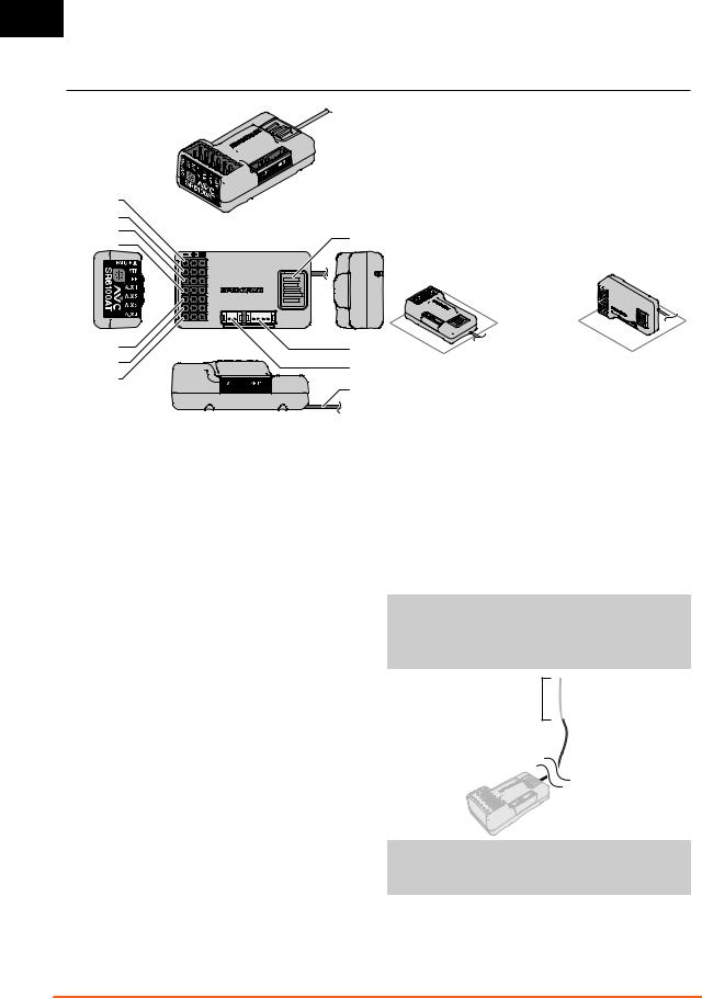
SR6100AT DSMR AVC TELEMETRY RECEIVER (SPM5120 ONLY)
Steering Port
Throttle Port
AUX 1 Port Bind Button
AUX 2 Port
AUX 3 Port |
XBus Port |
|
AUX 4 Port |
Voltage Port |
|
Battery/ |
||
Antenna |
||
PRG Port |
POWERING THE RECEIVER WITH A SEPARATE RECEIVER PACK
1.Connect the steering servo to the steering port (STR)
2.Connect the throttle servo to the throttle port (THR)
3.Connect the switch harness to the battery (BATT) port. The receiver will power on when a 3.5V–9.6V battery is connected to any of the ports on the servo rail or the BATT port.
POWERING THE RECEIVER WITH AN ESC
1.Connect the steering servo to the steering port (STR)
2.Connect the throttle servo to the throttle port (THR). Most ESCs will have an integrated BEC (battery eliminator circuit) which will power the ESC from the motor battery, through the throttle
lead. Connecting the ESC to any of the ports on the servo rail will power the receiver when the ESC is turned on.
SMART THROTTLE:
The SR6100AT receiver throttle port includes SMART Throttle.The SR6100AT receiver throttle port will automatically detect when a SMART Throttle compatible ESC is plugged in and the throttle port will begin to operate in SMART Throttle mode.
ESCs with SMART Throttle and IC series connectors can also pass along battery data from compatible Spektrum SMART batteries.
The SR6100AT is compatible with the Spektrum Firma™ line of ESCs for SMART Throttle.
NORMAL SERVO SIGNAL (PWM):
If a standard ESC or servo is plugged into the throttle port on the SR6100AT receiver, the throttle port will operate normally like any conventional RC system (PWM signal).
RECEIVER INSTALLATION
Install the SR6100AT receiver in the vehicle before binding the transmitter and receiver. The receiver can be mounted completely fl at (servo ports and bind button facing up) or completely perpendicular on its side. When binding the receiver, the AVC system automatically detects the orientation of the receiver.
If the receiver is angled, AVC technology may not function properly. If the orientation of the receiver is modifi ed after binding, you must rebind for AVC technology to function properly.
Mount the receiver fl at, two possibilities are 


 shown here


You may mount the receiver on any of its six sides, and it does not matter which direction the receiver is pointed. The receiver doesn’t even need to be square with the vehicle, as long as it is
fl at and level.
IMPORTANT: Do not use hook and loop tape to install the
SR6100AT receiver. Using hook and loop tape will affect the performance of the AVC system.
ANTENNA INSTALLATION
The SR6100AT receiver has a coaxial style antenna. Position the antenna vertically and away from the vehicle in an antenna tube. Make sure the tip of the antenna is as high as possible to maximize the signal strength.
NOTICE: Do not cut, kink, or modify the antenna. Damage to the coaxial portion of the antenna will reduce the performance of the antenna. Shortening or cutting off the 31mm tip will reduce the range to a small fraction of what it should be.
Active portion of antenna
NOTICE: Digital servos are required with the SR6100AT AVC receiver. Using analog servos with AVC technology will reduce the performance of the system and may cause the servos to overheat.
4 |
SPEKTRUM DX5C • TRANSMITTER INSTRUCTION MANUAL |

EN
DX5C CONTROLS AND SWITCHES
B |
J |
N |
|
A |
C |
O |
|
|
|
|
|
H |
|
P |
|
|
|
|
|
I |
|
I |
|
D |
|
|
|
|
Q |
|
|
|
|
|
|
E |
K |
|
|
|
|
|
|
F |
L |
|
|
|
|
|
|
G |
|
A: Trimmer Button A |
H: Power Button |
|
|
DefaultThrottle Trim |
I: Roller Wheel |
|
|
B: Trimmer Button B |
J: Antenna |
|
|
DefaultSteering Trim |
K: Steering Wheel |
|
|
C: Trimmer Button C |
L: Trigger (throttle/brake) |
|
|
D: Trimmer Button D |
M: Battery Door |
|
|
E: Trimmer Button E |
N: Data Port |
|
|
DefaultSteering Rate Up |
O: LCD Screen |
|
|
F: Trimmer Button F |
P: Back Button |
|
M |
DefaultBrake Rate Up |
Q: Clear Button |
G:Button G
DefaultTimer Start/Stop
INSTALLING BATTERIES
1.Remove the battery cover from the bottom of the transmitter.
2. Install 4 AA batteries as shown.
3. Install the battery cover.
MAIN SCREEN
The Main Screen displays information about the active model, including the Timer (when activated). To return to the Main
Screen at any time, press and hold the scroll wheel for at least 6 seconds.
A:Transmitter Battery Voltage
B:Model Name
C:Steering Rate
D:Timer (when activated)
E:Position of Steering (STR) trim
F:Position of Throttle (THR) trim
G:Position of Brake (BRK) trim
H:Position of AUX 1 trim
I: Position of AUX 2 trim
J: Position of AUX 3 trim
CAUTION: NEVER remove the transmitter batteries while the model is powered on. Loss of model control,
damage or injury may occur.
CAUTION: If using rechargeable batteries, charge only rechargeable batteries. Charging non-rechargeable
batteries may cause the batteries to burst, resulting in injury to persons and/or damage to property.
CAUTION: Risk of explosion if battery is replaced by an incorrect type. Dispose of used batteries according to national regulations.
A
B
C
D
E
F
G
H
I
J
SPEKTRUM DX5• TRANSMITTER INSTRUCTION MANUAL |
5 |
EN
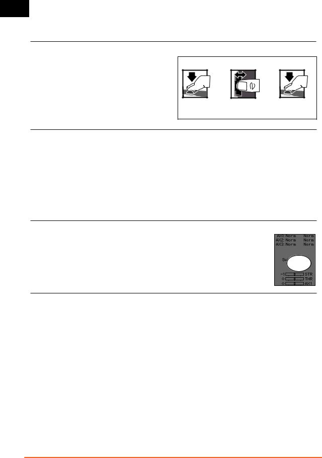
NAVIGATION
USING THE SCROLL WHEEL SELECTOR
•Scroll the scroll wheel to move through the screen content or change programming values. Click the scroll wheel to make a selection.
•Use the Back Button to go back to go to the previous screen (for example, to go from the Mixing Screen to the Function List).
•Use the Clear Button to return a selected value on a screen to the default setting.
•The Main Screen appears when you power on the transmitter. Click the scroll wheel once to display the Function List.
CLICK |
To Enter, Select or Exit a selection.
SCROLL |
To move between options or change values in an option.
HOLD |
Hold for 6 seconds and release to return to the Main screen.
INDIVIDUAL DIRECTION ADJUSTMENTS
In some instances, you may fi nd it necessary to independently adjust the control directions; for example, if you want more travel for left steering than right steering, perform the following steps:
1.Slide to the value you wish to change and press OK
2.When both directions are selected, move the control (steering or throttle) toward the control direction you wish to change. The selection box moves to the desired direction.
You do not need to hold the control in the desired direction.
3.To change the opposite direction, simply move the control in that direction.
4.Press OK to save the selection.
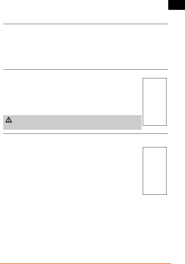
AUTO SWITCH SELECT
To easily select a switch in a function, such as a program mix, use the slide button to highlight the switch selection box, and press OK. The box around the switch should now fl ash. To select a switch, toggle the switch you wish to select. Verify the switch selection is now displayed as desired. When correct, press OK to select this switch and complete the switch selection.
Tip: The tick mark below shows the current switch position.
Use the slide button and press OK to turn the selected box black, indicating that the value or condition will act on that position.
SWITCH SELECTION TIP
If the system won’t allow INHIBIT to be changed, all switches are assigned to a different function. Un-assign a switch from another function to free it up for selection.
The DX5C does not allow switch assignments to be over-loaded,
there is only one switch to one function. Once a switch is
confi gured for a function, the switch assignment for that function must be disabled for the switch to be used for something else.
6 |
SPEKTRUM DX5C • TRANSMITTER INSTRUCTION MANUAL |
EN
MENU
Click the scroll wheel from the main screen to access the FUNCTION LIST. The FUNCTION LIST contains all the available menus on the
DX5C. The functions include:
• Model Select |
• Rates |
• Trim Setup |
• Model Name |
• Exponential |
• Aux Assign |
• Travel |
• Timer |
• Settings |
• Sub Trim |
• Bind/ Frame Rate |
• Utilities |
• Reverse |
• Mixing |
|
• Speed |
• AVC |
|
MODEL SELECT
Model Select enables you to access any of the 20 internal model memory locations in the Model Select list.
1.Scroll to the desired model memory in the Model Select list.
2.When the desired model memory is highlighted, press OK once to select the model. The transmitter returns to the Main Screen.
3.Add a new model by rolling to the bottom of the list. You will then be prompted with the Create New
Model screen, with the option to create a new model or cancel. If you select Cancel, the system will return to the Model Select function. If you select Create, the new model will be created and now be available in the model select list.
CAUTION: NEVER change the model in Model Select while operating a model. Changing the model memory interrupts the transmitter signal to the receiver and may cause loss of vehicle control, damage or personal injury.
MODEL NAME
Model Name enables you to assign a custom name to the current model memory. Model names can include up to 15 characters, including spaces.
To add letters to a Model Name:
1.Slide to the desired letter position and press OK. A fl ashing box appears.
2.Slide Up or Down until the desired character appears. Press OK to save the character.
3.Slide to the next desired letter position. Repeat Steps 1 and 2 until the Model Name is complete.
4.Select Back Button to return to the MENU.
To erase a character(s):
5.Press the Clear button while the character is selected.
6.Press the Clear button a second time to erase all characters to the right of the cursor.
SPEKTRUM DX5• TRANSMITTER INSTRUCTION MANUAL |
7 |
EN
MENU
TRAVEL
The Servo Setup menu contains the following functions:
Travel sets the overall travel or endpoints of the servo arm movement. Travel values range from 0–150% (Default is 100%).
To adjust Travel values:
1.Slide to the channel you wish to adjust and press OK.
2.Slide Up or Down to adjust the travel value. Press OK to save the selection.
SUB-TRIM
Subtrim offsets the entire range of servo travel including the center and endpoint positions.
 CAUTION Use only small sub-trim values may affect travel if full servo travel is used.
REVERSE
Use the Reverse menu to reverse the channel direction. For example, if the Steering servo moves Left, reversing the channel will move the Steering servo Right.
To reverse a channel direction:
1.Slide to Travel and press OK. Slide up or down until Reverse appears, then press OK again to save the selection.
2.Slide to the channel you wish to reverse and press OK.
If you reverse the Throttle channel, a confi rmation screen appears. Select YES to reverse the channel. A second screen appears, reminding you to bind your transmitter and receiver.
CAUTION: Always rebind the transmitter and receiver after reversing the Throttle channel. Failure to do so will result in the throttle moving to full throttle if failsafe activates.
Always perform a control test after making adjustments to confi rm the vehicle responds properly.
 CAUTION: After adjusting servos, always rebind the transmitter and receiver to set the failsafe position.
SPEED
The Speed menu enables you to slow the response time on any individual channel.
The Speed is adjustable from 100% to 1%.
To adjust the Speed:
1.Slide to the channel you wish to adjust and press OK.
2.Slide Up or Down to adjust the speed and press OK to save the selection.
3.Select a switch to activate/deactivate the function. If Switch ON is selected, the value will always be on for that function.
8 |
SPEKTRUM DX5C • TRANSMITTER INSTRUCTION MANUAL |
 Loading...