


 7s
7s
7


Instruction Manual
Bedienungsanleitung
Manuel d’utilisation
Manuale di istruzioni
Manual de instrucciones
SD Logo is a trademark of SD-3C, LLC

EN
NOTICE
All instructions, warranties and other collateral documents are subject to change at the sole discretion of Horizon Hobby, Inc. For up-to-date product literature, visit horizonhobby.com and click on the support tab for this product.
Meaning of Special Language
The following terms are used throughout the product literature to indicate various levels of potential harm when operating this product:
NOTICE: Procedures, which if not properly followed, create a possibility of physical property damage AND little or no possibility of injury.
CAUTION: Procedures, which if not properly followed, create the probability of physical property damage AND a possibility of serious injury.
WARNING: Procedures, which if not properly followed, create the probability of property damage, collateral damage and serious injury OR create a high probability of superficial injury.
 WARNING: Read the ENTIRE instruction manual to become familiar with the features of the product before operating. Failure to operate the product correctly can result in damage to the product, personal property and cause serious injury.
This is a sophisticated hobby product. It must be operated with caution and common sense and requires some basic mechanical ability. Failure to operate this Product in a safe and responsible manner could result in injury or damage to the product or other property. This product is not intended for use by children without direct adult supervision. Do not attempt disassembly, use with incompatible components or augment product in any way without the approval of Horizon Hobby, Inc. This manual contains instructions for safety, operation and maintenance. It is essential to read and follow all the instructions and warnings in the manual, prior to assembly, setup or use, in order to operate correctly and avoid damage or serious injury.
 WARNING AGAINST COUNTERFEIT PRODUCTS
Thank you for purchasing a genuine Spektrum product. Always purchase from a Horizon Hobby, Inc. authorized dealer to ensure authentic high-quality Spektrum product. Horizon Hobby, Inc. disclaims all support and warranty with regards, but not limited to, compatibility and performance of counterfeit products or products claiming compatibility with DSM or Spektrum.
WARRANTY REGISTRATION
Visit www.spektrumrc.com/registration today to register your product.
GENERAL NOTES |
PILOT SAFETY |
•Models are hazardous when operated and maintained incorrectly.
•Always install and operate a radio control system correctly.
•Always pilot a model so the model is kept under control in all conditions.
•Please seek help from an experienced pilot or your local hobby store.
•Contact local or regional modeling organizations for guidance and instructions about flying in your area.
•When working with a model, always power on the transmitter first and power off the transmitter last.
•After a model is bound to a transmitter and the model is set up in the transmitter, always bind the model to the transmitter again to establish failsafe settings.
•Always make sure batteries are fully charged before flying.
•Time flights so you can fly safely within the time allotted by your battery.
•Do a range check of the transmitter and the model before flying the model.
•Make sure control surfaces correctly respond to transmitter controls before flying.
•Do NOT fly a model near spectators, parking areas or any other area that could result in injury to people or damage to property.
•Do NOT fly during adverse weather conditions. Poor visibility can cause pilot disorientation and loss of control of a model. Wind, moisture and ice can cause loss of control and damage to a model.
•Do NOT point transmitter antenna directly at a model. The signal coming from the tip of the antenna is weak by comparison to the signal coming from other parts of the antenna.
•When a flying model does not respond correctly to controls, land the model and correct the cause of the problem.
2 |
SPEKTRUM DX7s • RADIO INSTRUCTION MANUAL |

EN
This manual covers the versatile Spektrum DX7s 7-channel computerized transmitter. Please visit www.spektrumrc.com for current information and firmware updates for DX7s programming.
This transmitter’s field-proven features are ready to be applied to your model’s setup, control and tuning.
BOX CONTENTS
• 2000mAh Ni-MH Transmitter Pack (Installed in transmitter) |
• |
SPM6803 Male/Female Bind plug |
|
• |
128MB SD Card |
• |
Manual (User/Inst./Quick Start Guide) |
• |
12V DC Power Supply (with 4 Clips) |
• |
Hex Wrench |
• |
SPMAR8000 8-Channel Receiver |
• |
DX7s Neck Strap |
|
(Not included with Transmitter only versions) |
• |
DX7s Decal Sheet |
TABLE OF CONTENTS
Quick Start Guide......................................................... |
4 |
Charging Your Transmitter............................................. |
5 |
Transmitter Batteries..................................................... |
5 |
Transmitter Functions................................................... |
6 |
Binding........................................................................ |
7 |
Using the transmitter.................................................... |
8 |
Antenna................................................................... |
8 |
Main Screen............................................................. |
8 |
Navigation.................................................................... |
9 |
System Settings........................................................... |
9 |
User Name............................................................... |
9 |
Contrast................................................................... |
9 |
Mode....................................................................... |
9 |
Selecting a Region (EU Version)................................ |
10 |
Selecting a Language.............................................. |
10 |
Acro and Heli setup.................................................... |
10 |
System Setup............................................................. |
11 |
Model Select.......................................................... |
11 |
Model Type............................................................. |
11 |
Model Name........................................................... |
11 |
Switch Select.......................................................... |
11 |
Model Reset........................................................... |
11 |
Model Copy............................................................ |
12 |
Warnings................................................................ |
12 |
Telemetry............................................................... |
12 |
Frame Rate............................................................ |
13 |
Acro.......................................................................... |
13 |
Wing Type.............................................................. |
13 |
Differential.............................................................. |
14 |
Flap System........................................................... |
14 |
Heli............................................................................ |
14 |
Swash Type............................................................ |
14 |
Throttle, Pitch and Tail Curves.................................. |
15 |
Gyro....................................................................... |
15 |
Governor................................................................ |
16 |
Flight Mode............................................................ |
16 |
Swashplate............................................................. |
16 |
Function List.............................................................. |
17 |
Servo Setup ........................................................... |
17 |
D/R & Exponential................................................... |
17 |
Throttle Cut............................................................ |
17 |
Range Test............................................................. |
18 |
Timer..................................................................... |
19 |
Monitor.................................................................. |
19 |
Trainer................................................................... |
19 |
Failsafes.................................................................... |
20 |
SmartSafe Failsafe.................................................. |
20 |
Hold Last Command................................................ |
20 |
Preset Failsafe........................................................ |
20 |
Receiver and servo information.................................... |
21 |
Receiver Installation................................................ |
21 |
Servo Installation.................................................... |
21 |
Servo Precautions................................................... |
21 |
Power System Requirements................................... |
21 |
Recommended Power System Guidelines................. |
21 |
Appendix.................................................................... |
22 |
Mode Conversion.................................................... |
22 |
Installing Optional LiPo Battery Pack........................ |
23 |
Servo Control.......................................................... |
24 |
Troubleshooting Guide................................................ |
27 |
Parts list.................................................................... |
27 |
AMA National Model Aircraft Safety Code..................... |
28 |
FCC Information......................................................... |
29 |
FAA Information.......................................................... |
29 |
Warranty and Service Contact Information.................... |
31 |
Parts Contact Information............................................ |
31 |
Compliance Information for the European Union............ |
31 |
Acro Model setup..................................................... |
134 |
Heli model setup....................................................... |
135 |
SPEKTRUM DX7s • RADIO INSTRUCTION MANUAL |
3 |

EN
QUICK START GUIDE
1. Install Main Receiver
Cover the main receiver in protective foam and attach the receiver in your gas or glow aircraft using rubber bands or hook and loop straps. In electric airplanes or helicopters, use doublesided foam tape to attach the main receiver to the model.
2. Install Remote Receiver
Install the remote receiver in the model using double-sided tape. Make sure the remote receiver antennas are more than 2 inches from the main receiver antennas. Always install remote antennas perpendicular to the main receiver’s antennas. Connect the main and remote receivers using the included 6-inch remote receiver lead.
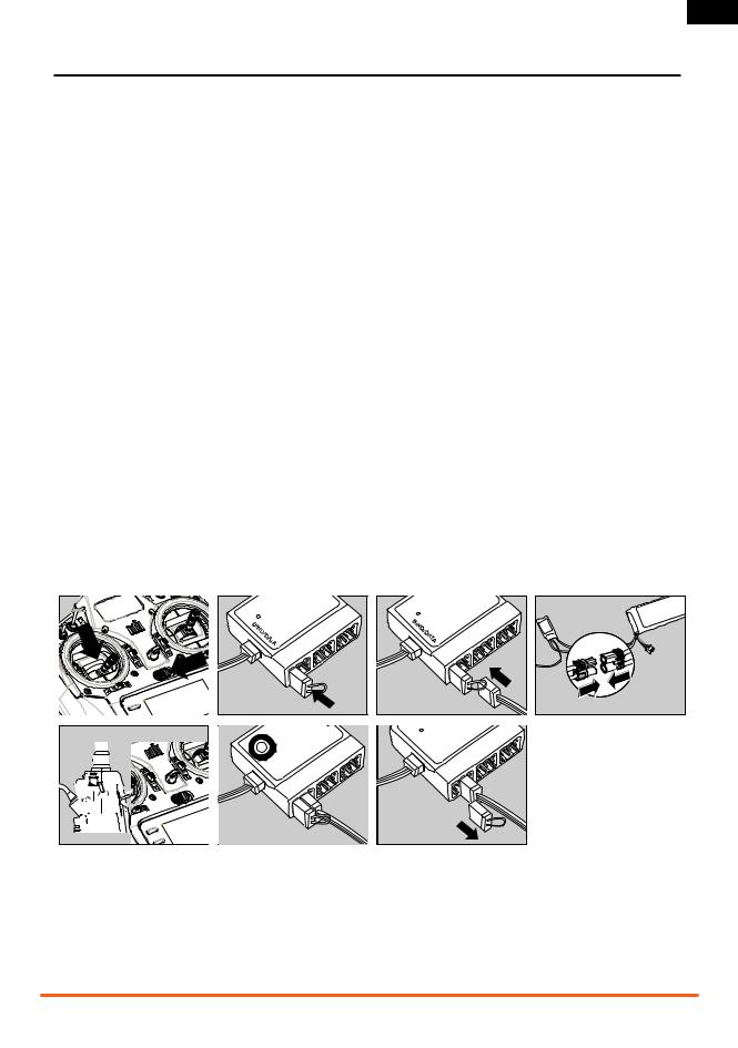
3.Connect Servos to the Main Receiver
4.Install the Telemetry Module
Install the telemetry module in the aircraft using double-sided tape. Connect the telemetry module to the receiver’s Data Port. Receiver voltage and Flight Log data displays on your telemetry screen. If you want an external voltage (main flight pack voltage) to show on the telemetry screen, connect the voltage telemetry sensor in the telemetry module. Connect voltage telemetry wires to the input lead on the aircraft’s ESC using solder, with the polarity red=positive and black=negative.
5. Charging Radio Batteries
First, connect the included power supply to the charging port on the side of the transmitter and place the transmitter on a nonflammable surface. Second, connect the AC adapter to a power outlet using the appropriate outlet clip. Charge the included NiMH battery for 10-12 hours.
 CAUTION: Do not overcharge batteries. Charging times greater than 12 hours may damage the battery and transmitter.
6.Bind the Receiver and Telemetry Module
A.Insert the bind plug in the receiver’s BIND/DATA port. In systems using a separate battery pack and 3-wire switch, insert the bind plug to the charge jack.
B.Power on the receiver. The LEDs on the receivers will flash.
C.Move transmitter sticks and switches to the desired failsafe positions (low throttle and neutral control positions).
D.Push in the Trainer/Bind button on the transmitter while powering on the transmitter. Once the transmitter has entered bind mode you can release the Bind button.
E.The LED on the receiver will show solid amber and the system will connect after several seconds.
F.Remove the bind plug.
Typical Electric - Receiver uses the ESC for power. Typical Glow/Gas - Uses receiver battery pack and 3-wire switch.
7. Charge and Test Receiver Batteries
Loss of power to the receiver and servos is the leading cause of failure. When using a receiver battery pack, make sure the pack is properly charged and check the voltage under a 1A or 2A load. Do not fly if the voltage is below 4.8V for a 4-cell pack while loaded. If the voltage falls below the receiver’s operating threshold (3.5 volts) at any time, an interruption in the link may occur.
8. Programming the Transmitter
Power on the transmitter, then power on the receiver. Make sure the model responds to the transmitter controls as desired. Use Servo Setup in the transmitter to reverse channels or adjust travel as needed. Program other functions as needed to safely control your model. Refer to additional sections of the manual for more information about programming your transmitter.
9. Re-Bind the System
Once the transmitter is programmed for your model, re-bind the system to set the failsafe position. If your model uses retracts, re-bind the system with retracts in the down position. If the signal is lost, the throttle servo will go to the preset position chosen during binding (normally low-throttle).
10. Range Check
A.With the system powered and the model restrained from flyaway, stand 30 paces (approximately 90 feet/30 meters) away from the model.
B.Face the model and hold the transmitter in your normal flying position. Go to the transmitter’s Range Test screen and press the Trainer button on the top of the transmitter. This causes reduced power output from the transmitter.
C.Operate transmitter controls to make sure you have total control of the model while holding down the trainer button.
D.If control issues exist, refer to the Troubleshooting Guide. If you continue to experience control issues, contact the appropriate Horizon Hobby Product Support office or go to
horizonhobby.com to find a local Spektrum distributor in your country of service.
4 |
SPEKTRUM DX7s • RADIO INSTRUCTION MANUAL |

EN
TRANSMITTER BATTERIES
Battery and Charging Precautions and Warnings
Failure to exercise caution while using this product and comply with the following warnings could result in product malfunction, electrical issues, excessive heat, FIRE, and ultimately injury and property damage.
•Read all safety precautions and literature prior to use of this product
•Never allow minors to charge battery packs
•Never drop charger or batteries
•Never attempt to charge damaged batteries
•Never attempt to charge a battery pack containing different types of batteries
•Never charge a battery if the cable has been pinched or shorted
•Never allow batteries or battery packs to come into contact with moisture at any time
•Never charge batteries in extremely hot or cold places (recommended between 50–80 degrees F or 10–27 degrees C) or place in direct sunlight
•Always disconnect the battery after charging, and let the charger cool between charges
•Always inspect a new battery before charging
•Always terminate all processes and contact Horizon Hobby if the product malfunctions
•Always keep batteries and charger away from any material that could be affected by heat (such as ceramic and tile), as they can get hot
•Always end the charging process if the charger or battery becomes hot to the touch or starts to change form (swell) during the charge process
Charging Your Transmitter
The DX7s includes a rechargeable NiMH battery pack. The DX7s has a built-in multi-chemistry charger designed to charge 4-cell NiMH and 2-cell LiPo batteries at a charge rate of 200mAh.
The charge port on the right side of the transmitter is not polarity-dependent.
 CAUTION: Never connect a peak detection charger or fast charger to your DX7s. These devices can damage the internal charge circuit. Use only the included 12V DC source.
Charge in a safe place NOT affected by the usual heat that comes from a charger and batteries during charging.
1.Power off your transmitter.
2.Connect the power supply’s connector to the transmitter’s charge port.
3.Connect the included 12-volt power supply to a power outlet using the appropriate outlet clip.
4.The blue LED on the front of the transmitter will illuminate during charging.
5.The blue LED will remain lit when charging the included NiMH battery. When charging the optional LiPo battery the blue LED will go off when charging is complete.
6.Disconnect the transmitter from the power supply when charging is complete.
7.Disconnect the power supply from a power outlet when the power supply is not in use.
For first use, charge the included NiMH battery pack for 10 to 12 hours until fully charged. Use the included 12V power supply. If you purchase the optional LiPo battery pack (SPMB4000LPTX), the initial charge can take up to 30 hours.
 CAUTION: Never leave a charging battery unattended.
Battery Alarm
The System Settings Screen allows you to change the battery type and low alarm settings.
•Always set the Battery Type to correspond with the chemistry of battery that is installed to enable the correct low voltage limit. When using a LiPo battery, you must connect the battery to the transmitter and then change the battery type in the programming. See Appendix for LiPo battery pack installation.
•An alarm will sound when the battery reaches the low voltage limit (4.3V for NiMH, 6.4V for LiPo).
 CAUTION: Never change the low voltage limit for LiPo batteries from 6.4V. Doing so could over-discharge the battery and damage both battery and transmitter.
SPEKTRUM DX7s • RADIO INSTRUCTION MANUAL |
5 |

EN
TRANSMITTER FUNCTIONS
|
Function |
|
Function |
|
A |
Antenna |
N |
Speaker Grill |
|
B |
Aux 2 Pot |
O |
SDI - SD Card |
|
C |
Mix (ACRO) /Throttle Hold (HELI) |
P |
Rudder Trim |
|
D |
Rudder Dual Rate (Mode 2) |
Q |
Throttle Trim (Mode 2) |
|
|
Flight Mode (Mode 1) |
|
Elevator Trim (Mode 1) |
X |
|
|
|
Throttle/Rudder Stick (Mode 2) |
|
E |
Aileron Dual Rate |
R |
|
|
|
Aileron/Elevator Stick (Mode 2) |
|
Elevator/Rudder Stick (Mode 1) |
|
F |
S |
Elevator Dual Rate |
|
|
|
Aileron/Throttle Stick (Mode 1) |
|
||
|
|
|
|
|
G |
Elevator Trim (Mode 2) |
T |
Flight Mode (Mode 2) |
|
|
Throttle Trim (Mode 1) |
|
Rudder Dual Rate (Mode 1) |
|
H |
Aileron Trim |
U |
Gear (ACRO)/Mix (HELI) |
|
I |
Roller |
V |
Flap (ACRO)/Gyro (HELI) |
|
J |
Charge Port |
W |
Trainer/Bind |
Y |
|
|
|
|
|
K |
On/Off Switch |
X |
Trainer Port |
|
L |
Clear Button |
Y |
Battery Cover |
|
M |
Back Button |
|
|
A |
|
|
|
|
The transmitter comes with a |
|
|
thin, clear, plastic film applied |
|
|
to some front panels for protec- |
|
W |
tion during shipping. Humidity |
|
|
|
|
|
and use may cause this film to |
|
|
come off. Carefully remove this |
V |
B |
film as desired. |
|
|
|
U |
C |
T |
|
D |
S |
E |
R |
F |
Q |
|
G |
P |
|
H |
|
|
I |
O |
|
J |
|
|
|
|
L |
|
|
M |
K |
|
N |
|
6 |
SPEKTRUM DX7s • RADIO INSTRUCTION MANUAL |
|
EN
BINDING
You must bind the receiver to the transmitter before it will operate. Binding teaches the receiver the specific code of the transmitter. Once bound, the receiver only connects to the transmitter when the previously bound model memory is selected. You will need to rebind the receiver after the model is set in the transmitter to fully program the model’s failsafe positions. If another model memory is selected, the receiver will not connect. This feature is called ModelMatch™ and prevents flying a model using the wrong model memory.
Binding Using the Receiver and Receiver Battery
1. |
2. |
3. |
5.
4. HOLD BUTTON WHILE POWERING ON 5.
Mode 2 Shown
1.Lower throttle to the lowest position and make sure the transmitter is powered off.
2.Insert bind plug into the BIND/DATA port.
3.Insert receiver battery into ANY open port. The receiver’s LED will flash when the receiver is ready to bind.
4.While pressing the Trainer/Bind button, power on the transmitter.
6.
6.
5.Release the Trainer/Bind button after the receiver has stopped flashing rapidly, once the receiver’s LED stays illuminated; this indicates the receiver is bound to the transmitter. The screen also provides binding information.
6.Remove the bind plug from the receiver.
Binding Using the Receiver and ESC
|
1. |
1. |
2. |
5. HOLD BUTTON WHILE POWERING ON |
|
5. HOLD BUTTON WHILE POWERING ON |
6. |
Mode 2 Shown |
|
2. |
3. |
4. |
3. |
|
4. |
6. |
7. |
|
7. |
|
|
1.Lower throttle to the lowest position and make sure the Modetransmitter2 Shown is powered off.
2.Insert bind plug into the BIND/DATA port.
3.Insert ESC plug into the THRO port.
4.Connect battery to ESC and turn on ESC switch, if available. The receiver’s LED will rapidly flash when the receiver is ready to bind.
5.While pressing the Trainer/Bind button, power on the transmitter.
6.Release the Trainer/Bind button after the receiver has stopped flashing rapidly, once the receiver’s LED stays illuminated; this indicates the receiver is bound to the transmitter. The screen also provides binding information.
7.Remove the bind plug from the receiver.
SPEKTRUM DX7s • RADIO INSTRUCTION MANUAL |
7 |

EN
USING THE TRANSMITTER
Antenna
The transmitter antenna bends and turns at the hinge (A) and only bends and turns to the front of the transmitter. The antenna cannot point to the back of the transmitter. Turn the antenna tip to point away from the model and ground. Signals transmit strongest from the antenna shaft, not the tip.
 WARNING: Do not pick up the transmitter by the antenna. Do not alter or put weight on the antenna. Damage to antenna parts can decrease transmitter signal strength, which can result
in loss of model control, injury or property damage.
A
NOTICE: While DSMX allows you to use more than 40 transmit- 


 ters simultaneously, when using DSM2 receivers, DSMX receiv-


 ers in DSM2 mode or transmitters in DSM2 mode, do not use


 more than 40 transmitters simultaneously.
SD Card
Use an SD Card and the Transfer SD Card screen in the System Setup list to to do the following:
• Import (copy) models from another DX7s transmitter
• Export (transfer) models to another DX7s transmitter
• Update AirWare™ software in the transmitter
• Share model files among DX7s transmitters.
Put an SD card in the SD card slot on the left side of the transmitter with the card’s label facing forward.
Main Screen
|
Function |
|
|
|
A |
Transmitter Battery Charge Level |
B |
C |
D |
|
|
|||
B |
Model Memory |
A |
|
|
|
|
|
|
CModel Name
DModel Type
E |
Elevator Trim (Mode 2) |
J |
|
|
|
E |
Throttle Trim (Mode 1) |
|
|
|
|
||
F |
Aileron Trim |
|
|
|
|
|
|
H |
|
|
|
||
|
|
|
|
|
|
|
G |
Digital Battery Voltage |
|
|
F |
||
(an alarm sounds and the screen flashes when battery charge gets |
I |
|
G |
|||
|
|
|
||||
|
down to 4.3V when using an NiMH battery or 6.4V for a LiPo battery.) |
|
|
|
|
|
HRudder Trim
ITimer
JThrottle Trim (Mode 2) Elevator Trim (Mode 1)
8 |
SPEKTRUM DX7s • RADIO INSTRUCTION MANUAL |

EN
NAVIGATION
Controls for Navigation
•Use the roller, Back and Clear buttons near the LCD screen for DX7s programming.
•Turn or press the roller to move through, select or change screen content.
•Use the Back button to go to the previous screen (for example, to go from the Mixing Screen to the Function List).
•Use the Clear button to change a selected value on a screen to its default setting (Some values do not have a default setting. For example, there is no default alarm type in the Timer Screen).
•While the transmitter is powered on, go to the Model Select screen by pressing the Clear and Back buttons at the same time. This is Direct Model Access, and will let you go to the Model Select Screen without powering off and on.
•Press and hold the roller while powering on the transmitter to show the System Setup list. This list is usually used when setting up a model and is not often used at the flying field.
No radio transmission occurs when a System Setup screen is displayed, preventing accidental damage to linkages and servos during changes to programming.
•Powering on the transmitter without touching any controls will show the Main Screen and the active model memory. Press the roller while on the Main Screen to show the Function List.
Press |
Enter, Choose or Exit
Turn |
Move between options or change value in an option
Hold |
Hold for 3 seconds and release to move to the Main Screen
SYSTEM SETTINGS
Use the System Setting screen to establish the overall transmitter setting that will apply to ALL model memories. These settings include: User Name, Contrast, Mode, Region and Language. If you select Mode One, then Mode One will be selected for all 20 model memories. Even when models are imported from an SD card, the system settings in the transmitter will remain.
Accessing System Settings
The Model Select function is used to change to a different model memory, typically when switching from the current model. You can store up to 20 models in the DX7s model memory. Access the model select function through the System Setup mode or through Direct Model Access (pressing the Clear and Back buttons at the same time). Direct Model Access allows you to access the model select function at any time the main screen or a telemetry screen is displayed.
User Name
User Name allows the identification of the owner to be programmed into the transmitter. The user name appears during the startup process at the lower left corner of the startup screen.
To Program a User Name
In the Systems Settings screen rotate the roller to highlight User Name then press.
Highlight the desired character position then press the roller to access that position. Rotate the roller to change to the desired character. Press to accept.
Contrast
In the Systems Settings screen rotate the roller to highlight User Contrast then press.
Rotate the roller to adjust the contrast (from 1 to 20) noting it on screen. Press to accept.
Repeat the process until the name is complete. Note that the User Name displays on the lower left of the startup screen.
Mode
See Appendix for Mode Conversion.
SPEKTRUM DX7s • RADIO INSTRUCTION MANUAL |
9 |
EN
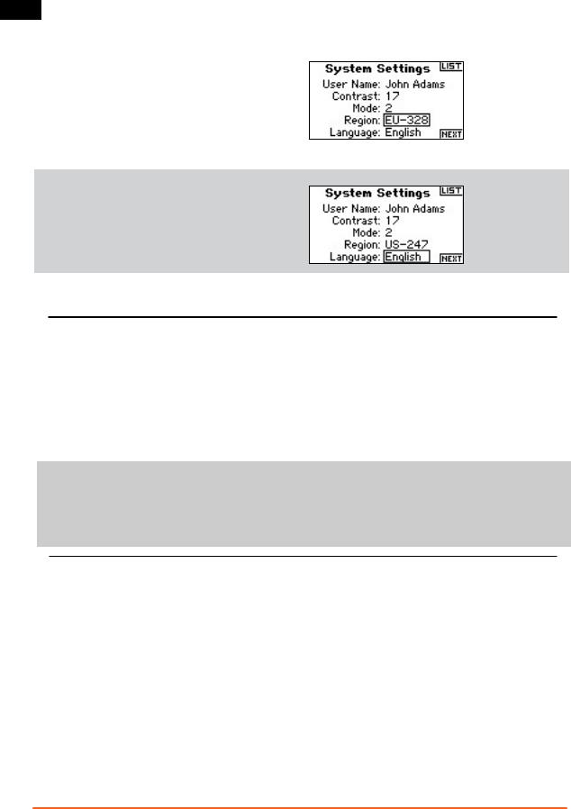
Selecting a Region (EU Version)
In the Systems Settings screen rotate the roller to highlight Region then press the roller to select the Region function. Note that two regions are available for EU radios only. EU328 (compliant for European countries) and FR328 compliant for France. US radios are fixed to US-247 USA compliant.
Rotate the roller to select the desired Region based on where the radio will be used. With Region selected, press the roller to accept that region.
Selecting a Language
In the Systems Settings screen rotate the roller to highlight
Language then press the roller to select the Language function.
Note that five Languages are available, English, German, Spanish,
French, and Italian.
Rotate the roller to select the desired Language.When the desired
Language is selected, press the roller to accept that Language.
ACRO AND HELI SETUP
Function List and System Setup list content is dependent on the Model Type (ACRO or HELI) selected for your active model memory.
ACRO
System Setup
Model Select
Model Type
Model Name
Wing Type (can enable other programming options)
Switch Select
Model Reset
Model Copy
Warnings
Telemetry (requires telemetry module and sensors)
Frame Rate Trainer System Settings
Transfer SD Card
Function List
Servo Setup |
Flap System (requires flap channel or channels) |
D/R & Expo |
Mixing |
Differential (requires dual ailerons, elevons or flaperons on sepa- |
Range Test |
rate channels) |
Timer |
Throttle Cut |
Monitor |
HELI
System Setup
Model Select
Model Type
Model Name
Swash Type (enable other programming options)
Switch Select
F-Mode Setup
Model Reset
Model Copy
Warnings
Telemetry (requires telemetry module and sensors)
Frame Rate Trainer System Settings
Transfer SD Card
Function List |
Gyro (requires Gyro channel) |
Servo Setup |
Governor (requires Governor channel) |
D/R & Expo |
Tail Curve (used for non-tail lock gyros) |
Throttle Cut |
Mixing |
Throttle Curve |
Range Test |
Pitch Curve |
Timer |
Swashplate (made available by Swash Type) |
Monitor |
|
|
10 |
SPEKTRUM DX7s • RADIO INSTRUCTION MANUAL |
 Loading...