

Page 1
CONTENTS
Warranty.........................3
Introduction .......................4
Basic Principles of PA Mixing .............5
Installation & Safety Precautions ...........7
Sicherheitshinweise ...............9
Precautions ...................10
Sicurezza ....................11
Precauciones de Seguridad ..........12
Connecting It Up....................13
Wiring It Up ......................14
Getting to Know Your Console ............18
Mono Inputs ...................18
Stereo Inputs ..................21
Group Section..................23
Master Section .................24
Using Your Spirit Live 4 Console ..........26
2
Applications ......................28
Care Of Your Mixer ..................34
Glossary ........................34
Typical Specifications .................36
Dimensions ......................37
System Block Diagram ................38
Panel Layout ......................39
Mark-up Sheets ....................40
Typical Connecting Leads ..............42
USERS GUIDEUSERS GUIDEUSERS GUIDEUSERS GUIDE
24
25
26
1 GRP 2
3 GRP 4
Page 2
IImmppoorrttaanntt
For your own safety and to avoid invalidation of the warranty please read this
manual carefully before connecting your Mixer and Power Supply Unit for the
first time.
SSaaffeettyy SSyymmbbooll GGuuiiddee
For your own safety and to avoid invalidation of the warranty all text marked with these Symbols should be
read carefully.
CAUTIONS
These must be followed carefully to avoid bodily injury.
WARNINGS
Must be observed to avoid damage to your equipment.
NOTES
Contain important information and useful tips on the
operation of your equipment.
© Soundcraft 1995, 2001
All rights reserved
Parts of the design of this product may be protected by worldwide patents
Part No. ZM0111 Issue 2
Soundcraft is a trading division of Harman Intrnational Industries Ltd. Information in this manual is
subject to change without notice and does not represent a commitment on the part of the vendor.
Soundcraft shall not be liable for any loss or damage whatsoever arising from the use of information
or any error contained in this manual.
No part of this manual may be reproduced, stored in a retrieval system, or transmitted, in any form
or by any means, electronic, electrical, mechanical, optical, chemical, including photocopying and
recording, for any purpose without the express written permission of Soundcraft.
Harman International Industries Ltd.,
Cranborne House,
Cranborne Road,
Potters Bar,
Hertfordshire,
EN6 3JN,
U.K.
Tel: +44 (0) 1707 665000
Fax: +44 (0) 1707 660742
http://www.soundcraft.com
Page 3

Page 3
WWaarrrraannttyy
1 Soundcraft is a trading division of Harman International Industries Ltd .
End User means the person who first puts the equipment into regular operation.
Dealer means the person other than Soundcraft (if any) from whom the End User purchased
the Equipment, provided such a person is authorised for this purpose by Soundcraft or its
accredited Distributor.
Equipment means the equipment supplied with this manual.
2 If within the period of twelve months from the date of delivery of the Equipment to the End
User it shall prove defective by reason only of faulty materials and/or workmanship to such an
extent that the effectiveness and/or usability thereof is materially affected the Equipment or the
defective component should be returned to the Dealer or to Soundcraft and subject to the
following conditions the Dealer or Soundcraft will repair or replace the defective components.
Any components replaced will become the property of Soundcraft.
3 Any Equipment or component returned will be at the risk of the End User whilst in transit (both
to and from the Dealer or Soundcraft) and postage must be prepaid.
4 This warranty shall only be valid if:
a) the Equipment has been properly installed in accordance with instructions contained in
Soundcrafts manual; and
b) the End User has notified Soundcraft or the Dealer within 14 days of the defect appearing;
and
c) no persons other than authorised representatives of Soundcraft or the Dealer have
effected any replacement of parts maintenance adjustments or repairs to the Equipment; and
d) the End User has used the Equipment only for such purposes as Soundcraft recommends,
with only such operating supplies as meet Soundcrafts specifications and otherwise in all
respects in accordance Soundcrafts recommendations.
5 Defects arising as a result of the following are not covered by this Warranty: faulty or negligent
handling, chemical or electro-chemical or electrical influences, accidental damage, Acts of God,
neglect, deficiency in electrical power, air-conditioning or humidity control.
6 The benefit of this Warranty may not be assigned by the End User.
7 End Users who are consumers should note their rights under this Warranty are in addition to
and do not affect any other rights to which they may be entitled against the seller of the
Equipment.
Page 4

Page 4
IINNTTRROODDUUCCTTIIOONN
C
ongratulations on your purchase of a SPIRIT LIVE 42mixer. Owning a Soundcraft console
brings you the expertise and support of one of the industrys leading manufacturers and
the results of over 22 years experience supporting some of the biggest names in the business.
Designed by engineers who understand the individual needs of musicians, SPIRIT LIVE 4
2
has been built to the highest standards using quality components and employing automated
assembly techniques beyond the reach of most manufacturers of compact mixers.
A rugged steel chassis is combined with moulded side trims to give protection and distinctive
appearance. Custom moulded controls, designed for the best `feel and visual clarity complement the styling, resulting in a truly professional product which is ideal for both touring and
fixed PA installations.
SPIRIT LIVE 42is available in 12, 16, 24 & 32 channel frame sizes. All frame sizes incorporate
removeable side cheeks to enable the console to be fitted compactly in a flight case.
SPIRIT LIVE 42incorporates circuit technology identical to that used on some of the most
sophisticated Soundcraft consoles. The input channels are able to accept a wide range of
Microphone and Line level signals from separate input sockets. Every channel features a wide
range gain control, Phase switch, 4-band Equalisation with swept Hi and Lo Mid ranges, plus a
Hi-Pass Filter, 6 Auxiliary Sends (2 pre-fade, 2 pre or post and 2 post-fade), PFL(Pre Fade
Listen), Peak LED, Panning to a Stereo Bus and routing in pairs to four Output Groups. Each
channel has a separate Direct Output and is controlled by a high-quality long throw fader. All
input channels may be assigned to a choice of four Mute Groups..
All frame sizes are provided as standard with dedicated stereo inputs. 1 stereo input is
included on the 12 channel frame and 2 stereo inputs on all other frame sizes. Each stereo
input comprises two separate input sections, one provided with comparable facilities to the
mono inputs, and one more basic input for a cassette or CD player which routes to the stereo
mix and two of the Aux outputs only.
The four Output Groups provide submixing to the Mix L/R, either as stereo pairs or as
mono sends to L & R. The Group outputs are available on separate connectors to feed external
equipment directly. Each Group section incorporates matrix sends, PFL monitoring & bargraph
metering. Four external Stereo Return inputs are provided for effects or submixing from external sources and these route to Mix or to a pair of Groups.
Two Matrix outputs receive sends from each Group or Mix L & R as required.
The Master section provides master level control for the Left, Right, Matrix and Auxiliary
Send buses, with separate AFL monitoring on each Matrix and Auxiliary output.
The Mix L/R and Group outputs all have insert points for the connection of external signal
processing or graphic equalisation.
Comprehensive Talkback facilities are provided, which allow a talkback microphone to be
routed to Mix L/R, Groups and Auxes 1-2 or 3-4. Six 12-segment, 3-colour peak reading LED
bargraph meters provide clear display of Mix L/R, Group and PFL signals. Pressing any PFL or
AFL switch puts the selected signal onto both sides of the headphones output and the L & R
bargraph meters in place of the Mix signal. Two LEDs monitor the status of the console power
supply.
SPIRIT LIVE 42is designed to be as user-friendly as possible, but a few minutes spent reading through this manual will help you become familiar with the product away from the pressure
of a live session, and allow you to gain full benefit from the superb performance offered by your
new mixer.
Above all, remember that your SPIRIT mixer is designed to extend your creativity. The
more you explore the controls and the effect they have on the sound output, the more you will
appreciate how you can influence and enhance the final sound.
Page 5

Page 5
BBAASSIICC PPRRIINNCCIIPPLLEESS OOFF PPAA MMIIXXIINNGG
T
here was a time when the P.A. system and the operator existed only to increase the
overall volume of the performers, so that they could be heard in a large room or
above high ambient noise levels. This just isnt true any more. The sound system and the
sound engineer have become an integral part of the performance, and the artists are
heavily dependent on the operators skill and the quality of the equipment.
The following introduction to the basics of mixing are included for the benefit of
those users who may not have any significant familiarity with sound equipment, and who
are baffled by the endless jargon used by engineers and artists alike.
TThhee MMiixxeerr
As one would expect, the main purpose of the mixer is to combine sounds, but under
precise control. This is why long-throw faders are essential on any professional mixer, to
give a responsive and smooth feel to the operator. The faders provide you with clear
and instinctive control of the final sound balance and like an artist playing an instrument
you should listen to the effect of your fader movements, not look at your hands.
Your SPIRIT LIVE 42mixer accepts a wide range of input signals via the microphone
input, for very low level signals, or a line input, for higher level signals from, for instance,
tape machines, effects processors, etc.
The mixer is split into two sections. The Inputs receive, match and process individ-
ual source signals, and distribute them at precise mix levels to either a stereo Mix output
or to one of the Groups. The Master section allows overall level control of all outputs,
and provides monitoring of the audio signal at many points in the mixer, either on headphones or meters.
The Equaliser controls are the most flexible and potentially destructive feature of
the mixer. They have a similar effect on the frequency response of the input channel as
the tone controls on a hi-fi system, but with much greater precision, and allow particular
characteristics of the input signal to be emphasised or reduced. It is very important that
you become familiar with the effect each control has on the sound and this is best
achieved by spending time listening to the effect of each control on a well-known track
played through the mixer.
The Auxiliary Sends provide a way of routing the input signals to a number of secondary outputs, for artists foldback, echo units or additional speaker outputs.
The Pan control adjusts the position of the input signal within the stereo mix, and
can be swept from full left, through to full right. This allows particular artists to retain
their correct spatial position within the mix, and can be valuable for live effects.
Pre-Fade-Listen(PFL) allows you to monitor the signal at many points in the mixer.
Pressing any PFL switch places the signal at that particular point onto the headphones
and the right meter, to check the quality of the signal or to pin-point problems. Using
PFL will not affect the signals on the outputs from the desk.
Each mono input channel and the Mix and Group outputs have an Insert `A gauge
jack socket, which is a break point in the signal path. It allows the signal to be taken out
of the mixer, through an external piece of equipment and then back into the mixer
directly after its original exit point. The Insert point is normally bypassed by the `A
gauge jack socket contacts, and is only brought into operation when a plug is inserted.
Typical uses would include Effects Processors, Limiters, additional Equalisers or Delay
units. In addition, each channel has a Direct output which may also be used to feed
external equipment such as multitrack tape machines or effects devices.
Page 6
Page 6
The terms PRE and POST are often used in the context of Inserts, Equalisers and
Auxiliary Sends, and describe whether that facility is placed before (Pre) or after (Post)
another particular section. This is explained further in the Glossary.
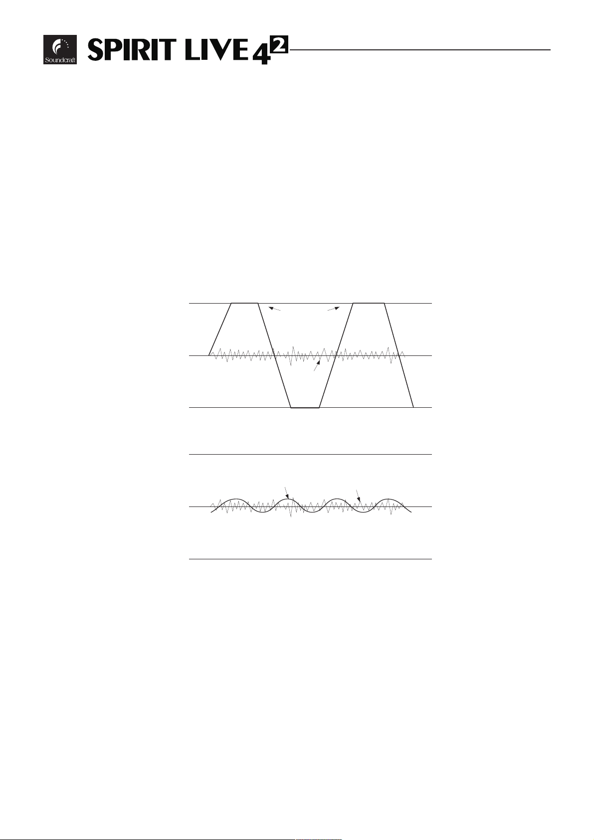
A mixer is often judged, amongst other factors, by the amount of Headroom available. This is a measure of the reserve available to cope with sudden peaks in the input
signal, without distortion caused by Clipping, when the signal becomes so high that it
would exceed the power supply rail voltages and is as a result limited. This commonly
occurs where gain settings are incorrectly set or where sources are improperly matched
to the mixer input. If the source signal is too high, clipping and distortion results. If the
signal is too low it becomes masked by the background noise which is present to some
degree in all mixers. The diagram below illustrates this point.
Clipped
Signal
Noise
If the signal level is too high, clipping distortion
may occur.
Signal
If the signal level is too low it may be masked
by the noise.
Noise
Page 7

Page 7
IInnssttaallllaattiioonn aanndd SSaaffeettyy PPrreeccaauuttiioonnss
IInnssttaalllliinngg tthhee MMiixxeerr
C
orrect connection and positioning of your mixer is important for successful and troublefree operation. The following sections are intended to give guidance with cabling, connec-
tions and configuration of your mixer.
o Choose the mains supply for the sound system with care, and do not share sockets or earth-
ing with lighting dimmers.
o Position the mixer where the sound can be heard clearly, preferably within the audience.
o Run audio cables separately from dimmer wiring, using balanced lines wherever possible. If
necessary, cross audio and lighting cables at right angles to minimise the possibility of interference. Keep unbalanced cabling as short as possible.
o Check your cables regularly and label each end for easy identification.
SSAAFFEETTYY PPRREECCAAUUTTIIOONNSS
For your own safety and to avoid invalidation of the warranty
please read this section carefully.
The SPIRIT LIVE 42mixer must only be connected through the
Power Supply supplied.
The wires in the mains lead are coloured in accordance with the following code:
Earth: Green and Yellow (Green/Yellow - US)
Neutral: Blue (White - US)
Live: Brown (Black - US)
As the colours of the wires in the mains lead may not correspond with the coloured markings
identifying the terminals in your plug, proceed as follows:
The wire which is coloured Green and Yellow must be connected to the terminal in the plug
which is marked with the letter E or by the earth symbol.
The wire which is coloured Blue must be connected to the terminal in the plug which is
marked with the letter N.
The wire which is coloured Brown must be connected to the terminal in the plug which is
marked with the letter L.
Ensure that these colour codings are followed carefully in the event of the plug being changed.
To avoid the risk of fire, replace the mains fuse only with the
correct value fuse, as indicated on the power supply.
Page 8

Page 8
CCAAUUTTIIOONNSS
Do not install near any heat sources such as radiators, heat resistors, stoves, or other apparatus (including
amplifiers) that produce heat.
Do not use this apparatus near water.
Protect the power cord from being walked on or pinched particularly at plugs, convenience receptacles
and the point where they exit from the apparatus.
Only use cables and hardware specified by the manufacturer.
Unplug this apparatus during lightning storms or when unused for long periods of time.
Refer all servicing to qualified service personnel.
It is recommended that all maintenance and service on the product should be carried out by Soundcraft or
its authorised agents. Soundcraft cannot accept any liability whatsoever for any loss or damage caused by
service, maintenance or repair by unauthorised personnel.
WARNINGS
Read these instructions.
Keep these instructions.
Heed all warnings.
Follow all instructions.
This unit contains no user serviceable parts. Refer all servicing to a qualified service engineer, through the
appropriate Soundcraft dealer.
Clean only with a damp cloth.
DO Install in accordance with the manufacturers instructions.
Page 9
Page 9
SSIICCHHEERRHHEEIITTSSHHIINNWWEEIISSEE
Das SPIRIT LIVE 42darf nur an das entsprechend mitgelieferte Netzgerät
angeschlossen werden !
Die Verdrahtung der Hauptleitungen stimmt mit folgendem Farbcode überein:
Grün/gelb Gehäuseschutzleiter
Blau Mittelpunktsleiter
Braun Phase
Falls diese Festlegung nicht mit der Belegung der Steckkontakte in der Steckdose übereinstimmt, gehen Sie bitte
folgendermaßen vor:
l Die grün/gelbe Leitung muß an den mit dem Erde-Symbol bzw. Buchstabe E gekennzeichneten Steckkontakt
angeschlossen werden.
l Die braune Leitung ist mit der Anschlußklemme zu belegen, die mit dem Buchstaben L gekennzeichnet ist. An
diesem Pol liegt liegt die Phase an (stromführender Pol).
l Die blaue Leitung ist mit der Anschlußklemme zu belegen, die mit dem Buchstaben N gekennzeichnet ist.
Achten Sie auch bei einem Steckdosenwechsel auf den Farbcode an den Steckkontakten der Steckdose.
Die mitgelieferten Netzgeräte enthalten keine Komponenten, die vom Benutzer gewechselt werden könnten.
Eventuelle Serviceleistungen nur qualifiziertem Fachpersonal oder dem SPIRIT-Fachmann überlassen !
Um die Gefahr eines Elektrobrandes zu verhindern, dürfen nur Hauptsicherungen am
Netzgerät ersetzt werden, wie sie entsprechend auf dem Gerätegehäuse aufgeführt
sind.
WWAARRNNUUNNGGEENN
Betreiben Sie das Gerät nicht in direkter Nähe von Wärmequellen wie Radiatoren,
Wärmespeichern, Heizkörpern oder anderen Vorrichtungen (inklusive Leistungsverstärkern), die
Wärme produzieren
Schützen Sie das Gerät vor Feuchtigkeit und betreiben Sie es nicht in der Nähe von fließendem
Wasser.
Verlegen Sie das Netzkabel so, daß es keinen äußeren Belastungen ausgesetzt ist. Achten Sie
besonders darauf, daß die Stecker nicht gequetscht werden oder an den Netz- bzw.
Gerätebuchsen unter Zug stehen.
Verwenden Sie ausschließlich vom Hersteller empfohlene Kabel und Hardware.
Entfernen Sie das Gerät vom Netz im Falle eines Gewitters oder wenn Sie es für längere Zeit nicht
benutzen werden.
Wenden Sie sich im Servicefall ausschließlich an qualifiziertes Fachpersonal.
Es wird empfohlen, alle Wartungsarbeiten und Reparaturen direkt von Soundcraft oder einem
autorisierten Vertreter ausführen zu lassen. Soundcraft kann keine Verantwortung für Verluste
oder Schäden in jeglicher Form übernehmen, die aufgrund von Serviceleistungen,
Wartungsarbeiten oder Reparaturen durch unqualifiziertes Personal auftreten.
HHIINNWWEEIISSEE
Lesen Sie diese Anleitung sorgfältig durch.
Bewahren Sie diese Anleitung auf.
Leisten Sie allen Hinweisen in jedem Fall Folge.
Leisten Sie allen Informationen in dieser Anleitung unbedingt Folge.
Dieses Gerät enthält keine Bauteile, die vom Anwender ausgetauscht werden können. Wenden Sie
sich im Reparaturfall an Ihren Soundcraft-Händler bzw. an qualifiziertes Fachpersonal.
Reinigen Sie das Gerät nur mit einem trockenen Tuch.
FÜHREN SIE die Installation gemäß den Anleitungen des Herstellers durch.
Page 10

Page 10
PPRREECCAAUUTTIIOONNSS
La console SPIRIT LIVE 42doit impérativement être connectée avec lalimentation
fournie.
Les conducteurs du câble secteur sont identifiés comme suit :
Vert/Jaune Terre
Bleu Neutre
Brun Phase
Pour éviter tout risque dincendie, remplacez le fusible uniquement avec un fusible de la
valeur correcte indiquée sur lalimentation.
PPRREECCAAUUTTIIOONNSS
N'installez pas l'appareil à proximité de sources de chaleur telles que radiateurs, résistances chauf-
fantes, réchauds ou autres appareils susceptibles de produire de la chaleur (y compris les amplificateurs) .
N'utilisez pas cet appareil près d'un point d'eau.
Veillez à ce que le cordon d'alimentation ne soit ni écrasé ni pincé, en particulier au niveau de l'ap-
pareil et de la prise secteur murale.
Veillez à n'utiliser que les câbles, connecteurs et accessoires recommandés par le fabricant.
Débranchez l'appareil en cas d'orage ou d'inutilisation prolongée.
Adressez-vous à un technicien qualifié pour toute réparation.
La maintenance et les réparations doivent être assurées par un revendeur agréé par Soundcraft ou
son distributeur. La garantie ne pourra pas s'appliquer en cas de dommage causé par un réparateur
non agréé.
AAVVEERRTTIISSSSEEMMEENNTTSS
Lisez attentivement ces instructions.
Conservez ces instructions
Tenez compte de ces instructions.
Suivez toutes les instructions.
Aucun élément de cet appareil n'est réparable par l'utilisateur. Adressez-vous à un technicien qual-
ifié pour toute réparation par l'intermédiaire du distributeur Soundcraft.
Nettoyez l'appareil avec un chiffon sec.
L'installation doit être conforme aux instructions des fabricants.
Page 11

Page 11
SSIICCUURREEZZZZAA
Il mixer SPIRIT LIVE 42deve essere collegato
allalimentatore in dotazione.
I cavi nella presa sono colorati secondo il seguente codice:
Terra: Verde e Giallo
(Verde/Giallo - US)
Neutro: Blu
(Bianco - US)
Vivo: Marrone
(Nero - US)
Poichè i colori potrebbero non corrispondere a quelli dei terminali nella presa, procedere come segue:
l Il cavo Verde e Giallo va collegato al terminale indicato con E o con il simbolo di terra
l Il cavo Blu va collegato al terminale indicato con N.
l Il cavo Marrone va collegato al terminale indicato con L
Assicurarsi che questi colori siano rispettati in caso di sostituzione della spina.
Per evitare il rischio di incendi sostituire il fusibile solo con uno del valore indicato.
AAVVVVEERRTTEENNZZEE
Non installare vicino a fonti di calore come radiatori, caloriferi, stufe o altre apparecchiature che
producono calore (amplificatori inclusi).
Non utilizzare queste apparecchiature vicino all'acqua.
Non manomettere in alcun modo il cavo di alimentazione.
Proteggere il cavo da evenutali calpestii ed evitare di strappare il cavo dalla presa.
Usare solo cavi indicati dal fabbricante.
Scollegare l'alimentazione durante i temporali o quando l'apparecchio non viene utilizzato per
lunghi periodi di tempo.
Per l'assistenza rivolgersi solo a personale qualificato.
Si raccomanda che la manutenzione ed il servizio assistenza sul prodotto siano eseguiti da
Soundcraft o dai suoi distributori autorizzati. Soundcraft non accetta nessuna responsabilita per
alcuna perdita o danno causati da assistenza e riparazioni eseguiti da personale non autorizzato.
AATTTTEENNZZIIOONNEE
Leggere queste istruzioni.
Conservare queste istruzioni.
Fare attenzione a tutte le avvertenze.
Seguire tutte le istruzioni.
Questa unita non contiene parti di ricambio. Fare riferimento ai centri di assistenza qualificati attra-
verso il rivenditore Soundcraft autorizzato.
Pulire solo con un panno morbido ed asciutto.
Installare seguendo le indicazioni fornite dal costruttore.
Page 12

Page 12
PPRREECCAAUUCCIIOONNEESS DDEE SSEEGGUURRIIDDAADD
La consola SPIRIT LIVE 42debe ser conectada únicamente a la fuente de alimentación
suministrada.
Los conductores en el terminal de red se encuentran codificados por co-lores del siguiente modo:
Tierra: Verde y Amarillo
Neutro: Azul
Vivo: Marrón
En caso de que los colores de los conductores del terminal de red no coincidan con los colores de las marcas que
identifican los terminales en su enchufe, proceda del siguiente modo:
l El conductor de color verde y amarillo debe conectarse al terminal del enchufe que este marcado con la letra E
o por el símbolo de tierra.
l El conductor de color azul debe conectarse al terminal del enchufe que este marcado con la letra N, o sea, de
color negro.
l El conductor de color marrón debe conectarse al terminal del enchufe que este marcado con la letra L, o sea,
de color rojo.
Asegúrese de seguir cuidadosamente este código de colores en caso de que deba sustituirse el enchufe.
Para evitar riesgos de incendio, al reemplazar un fusible deberá tratar siempre de man-
tener su valor, tal como se indica en la fuente de alimentación.
PPRREECCAAUUCCIIOONNEESS
No instalar cerca de fuentes de calor, tales como radiadores, resistencias de calor, estufas u otro
aparato emisor de calor (incluyendo amplificadores).
No usar este aparato cerca del agua.
Proteger el cable de alimentación para que no sea pisado o pellizcado, especialmente en los conec-
tores y en el punto de la salida del aparato.
Utilizar solamente cables y accesorios especificados por el fabricante.
Desconectar este aparato durante tormentas eléctricas o cuando no se vaya a utilizar por un largo
período de tiempo.
Cualquier reparación tiene que efectuarse por personal cualificado.
Se recomienda que el mantenimiento y cualquier reparación del producto sea efectuado por
Soundcraft o sus distribuidores autorizados. Soundcraft no aceptará ninguna reclamación por pérdidas o daños causados en mantenimiento, reparaciones u otro servicio efectuado por personas no
autorizadas.
AADDVVEERRTTEENNCCIIAASS
Lea estas instrucciones atentamente.
Guarde estas instrucciones para futuras consultas.
Haga caso de todas las advertencias.
Siga todas las instrucciones
Esta unidad no contiene partes reparables por el usuario. Llame al servicio técnico del represen-
tante de Soundcraft en su zona.
Limpiar solo con un paño húmedo.
Instalar de acuerdo con las instrucciones del fabricante.
Page 13
Page 13
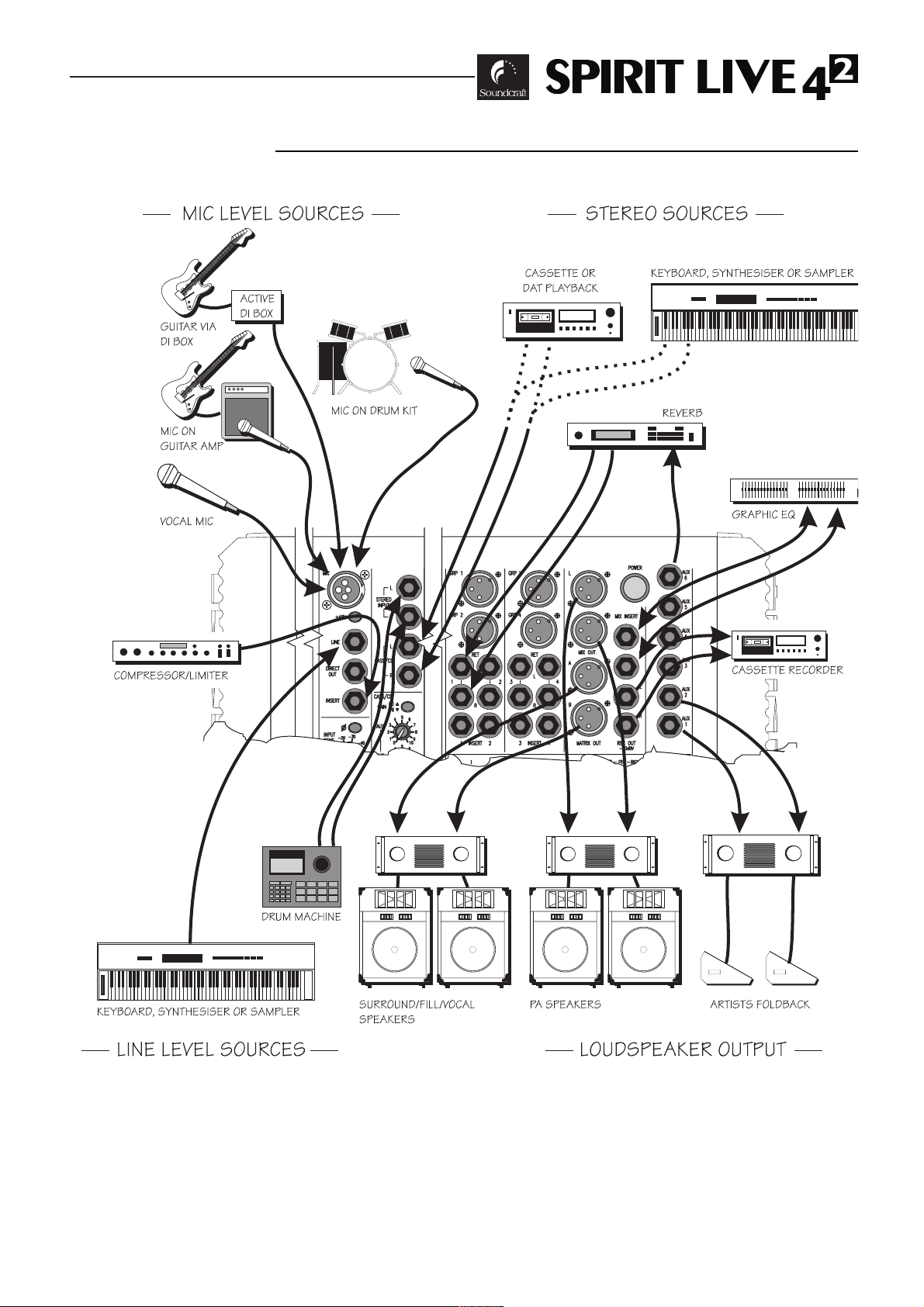
CCOONNNNEECCTTIINNGG IITT UUPP
Page 14
WWIIRRIINNGG IITT UUPP
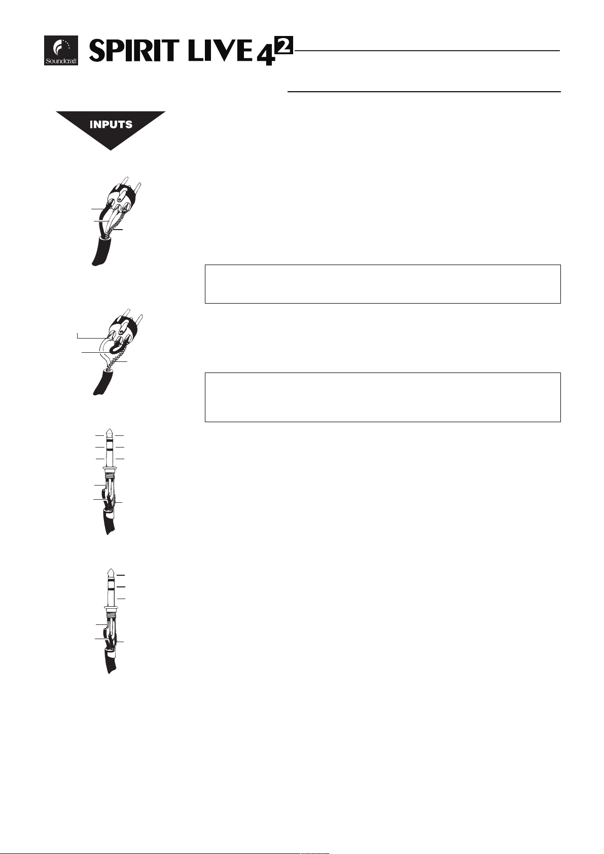
MMIICC IINNPPUUTT
The mic input accepts XLR-type connectors and is designed to suit a wide range of
BALANCED or UNBALANCED low-level signals, whether from delicate vocals
requiring the best low-noise performance or close-miked drum kits needing maximum
headroom. Professional dynamic, condenser or ribbon mics are best because these
will be LOW IMPEDANCE. While you can use low-cost HIGH IMPEDANCE mics,
you do not get the same degree of immunity to interference on the microphone cable
and as a result the level of background noise may be higher. If you turn the PHANTOM POWER on, the socket provides a suitable powering voltage for professional
condenser mics.
DO NOT use unbalanced sources with the phantom power switched on. The
voltage on pins 2 & 3 of the XLR connector may cause serious damage.
The input level is set using the INPUT SENS knob.
The LINE input offers the same gain range as the MIC input, but at a higher input
impedance. This is suitable for most line level sources, and provides the gain needed
for lower level keyboards and high impedance microphones.
WARNING - Start with the INPUT SENS knob at the 0 position when
plugging high level sources into the LINE input to avoid overloading the
input channel or giving you a very loud surprise!
LLIINNEE IINNPPUUTT
Accepts 3-pole `A gauge jacks, or 2-pole mono jacks which will automatically
ground the cold input. Use this input for sources other than mics, such as keyboards,
drum machines, synths, tape machines or guitars. The input is BALANCED for low
noise and immunity from interference, but you can use UNBALANCED sources by
wiring up the jacks as shown, although you should then keep cable lengths as short as
possible to minimise interference pick-up on the cable. Refer to the section How to
Prevent Interference later in this manual. Note that the ring must be grounded if the
source is unbalanced. Set the input level using the INPUT SENS knob, starting with
the knob turned fully anticlockwise. Plugging into the LINE input automatically cuts off
the MIC input.
IINNSSEERRTT PPOOIINNTT
The unbalanced, pre-EQ insert point is a break in the channel signal path, allowing
limiters, compressors, special EQ or other signal processing units to be added in the
signal path. The Insert is a 3-pole A gauge jack socket which is normally bypassed.
When a jack is inserted, the signal path is broken, just before the EQ section.
The signal from the channel appears on the TIP of the plug and is returned on the
RING, with the sleeve as a common ground.
Page 14
2. Hot(+ve)
3. Cold(-ve)
2. Hot(+ve)
Link 3
to 1
Balanced
3 pole Jack
Hot (+ve)
Cold (-ve)
Gnd/Screen
Ring
Ring
Balanced Mic
XLR
1. Screen
Unbalanced Mic
XLR
Unbalanced
3 pole Jack
Signal
Gnd/Screen
Gnd/Screen
Tip
Sleeve
Inserts
Signal Send
Signal Return
Gnd/Screen
Tip
Sleeve
1. Screen
Page 15

Page 15
SSTTEERREEOO IINNPPUUTTss,, CCAASSSS//CCDD IINNPPUUTTSS
Accept 3-pole `A gauge jacks, or 2-pole mono jacks which will automatically ground
the cold input. Use these inputs for sources such as keyboards, drum machines, synths,
tape machines or as returns from processing units. The input is BALANCED for low
noise and immunity from interference, but you can use UNBALANCED sources by
wiring up the jacks as shown, although you should then keep cable lengths as short as
possible to minimise interference pick-up on the cable. Note that the ring must be
grounded if the source is unbalanced. Mono sources can be fed to both paths by plugging into the Left jack only
.
SSTTEERREEOO RREETTUURRNNSS
Similar to the Stereo Inputs. Input gain is sufficient to allow the connection of +4dBu
professional or -10dBV semi-professional equipment.
MMiixx IINNSSEERRTTSS,, GGRROOUUPP IINNSSEERRTTSS
The unbalanced, pre-fade Mix insert point is a break in the output signal path to allow
the connection of, for example, a compressor/limiter or graphic equaliser. The Insert is
a 3-pole A gauge jack socket which is normally bypassed. When a jack is inserted, the
signal path is broken, just before the mix fader.
The mix signal appears on the TIP of the plug and is returned on the RING. A Y
lead may be required to connect to equipment with separate send and return jacks as
shown below:
Mix Outputs
MMIIXX,, GGRROOUUPP && MMAATTRRIIXX
The Mix, Group and Matrix outputs are on 3-pole XLR sockets, wired as shown on
the left and below, and incorporate impedance balancing, allowing long cable runs to balanced amplifiers and other equipment.
Group Outputs
Matrix Outputs
1. Screen
Mix & Group Inserts
Tip
Ring
3. Signal -
2. Signal +
Signal Send
Signal Return
Gnd/Screen
Sleeve
Aux Outputs
Rec Outputs
Direct Outputs
Signal +
Signal Screen
Headphones
Left Signal
Right Signal
Ground
Insert Point
Signal Send
Screen
Signal Return
Send to External Device
Return from External Device
From LIVE 4
Impedance Balanced
Output
From LIVE 4
Impedance Balanced
Output
2
2
Signal
Screen
Signal
(a) Balanced Connection
Signal Ground
(b) Unbalanced Connection
To External Device
To External Device
Screen
Signal Ground
Experience has shown that sometimes it is better
not to connect screen at external device end.
Page 16

Page 16
AAUUXX OOUUTTPPUUTTSS,, DDiirreecctt OOUUTTPPUUTTSS
The Aux and Channel Direct outputs are on 3-pole A gauge jack sockets, wired as
shown on the left, and incorporate impedance balancing, allowing long cable runs to balanced amplifiers and other equipment.
HHEEAADDPPHHOONNEESS
The PHONES output is a 3-pole A gauge jack, wired as a stereo output as shown,
suitable for headphones of 200W or greater. 8W headphones are not recommended.
PPoollaarriittyy
You will probably be familiar with the concept of polarity in electrical signals and this
is of particular importance to balanced audio signals. Just as a balanced signal is highly
effective at cancelling out unwanted interference, so two microphones picking up the
same signal can cancel out, or cause serious degradation of the signal if one of the cables
has the +ve and -ve wires reversed. This phase reversal can be a real problem when
microphones are close together and you should therefore take care always to connect
pins correctly when wiring audio cables. The mono inputs are provided with a Phase (f)
switch to reverse the polarity of a selected input if a phasing problem is suspected.
GGrroouunnddiinngg aanndd SShhiieellddiinngg
For optimum performance it is vital that all signals are referenced to a solid, noisefree earthing point and that all signal cables have their screens connected to ground. To
avoid earth `loops, use balanced connections where possible and ensure that all cable
screens and other signal earths are connected to ground only at their source and not at
both ends.
If the use of unbalanced connections is unavoidable, you can mimimise noise by following these wiring guidelines:
l On INPUTS, unbalance at the source and use a twin, screened cable as though it
were balanced.
l On OUTPUTS, connect the signal to the +ve output pin, and the ground of the out-
put device to -ve. If a twin screened cable is used, connect the screen only at the
mixer end.
l Avoid running audio cables or placing audio equipment, close to thyristor dimmer
units or power cables.
l Noise immunity is improved significantly by the use of low impedance sources, such
as good quality professional microphones or the outputs from most modern audio
equipment. Avoid cheaper high impedance microphones, which may suffer from
interference over long cable runs, even with well-made cables.
Page 17

Page 17
FFaauulltt FFiinnddiinngg GGuuiiddee
Repairing a sound mixing console requires specialist skills, but basic Fault Finding is
within the scope of any user if a few basic rules are followed.
l Get to know the Block Diagram of your console (see page 38). It is just like following
a road map.
l Get to know what each component in the system is supposed to do.
l Learn where to look for common trouble spots.
The Block Diagram (see page 38) is a representative sketch of all the components of
the console, showing how they connect together and how the signal flows through the
system. Once you have become familiar with the various component blocks you will find
the Block Diagram quite easy to follow and you will have gained a valuable understanding
of the internal structure of the console.
Each Component has a specific function and only by getting to know what each part
is supposed to do will you be able to tell if there is a genuine fault! Many `faults are the
result of incorrect connection or control settings which may have been overlooked.
Basic Troubleshooting is a process of applying logical thought to the signal path
through the console and tracking down the problem by elimination.
l Swap input connections to check that the source is really present. Check both Mic
and Line inputs.
l Eliminate sections of the channel by using the insert point to re-route the signal to
other inputs that are known to be working.
l Route channels to different outputs or to auxiliary sends to identify problems on the
Master section.
l Compare a suspect channel with an adjacent channel which has been set up identical-
ly. Use PFL and AFL to monitor the signal in each section.
Page 18

Page 18
GGEETTTTIINNGG TTOO KKNNOOWW YYOOUURR CCOONNSSOOLLEE
MMOONNOO IINNPPUUTT CCHHAANNNNEELL
T
wo inputs are available to the mono input channel, via XLR connector (normally for
microphone sources) or 3-pole 1/4 A gauge jack socket for higher level signals
such as keyboards, drum machines, synths or tape machines. Both input sockets are
permanently active, and may be used simply by plugging the source into the required
input. You do not need to unplug anything in the MIC socket if you want to use the
LINE input. The new UltraMic+ input provides very wide gain control without the
need for a pad, high CMRR and +28dBu input capability.
An impedance balanced DIRECT output is provided, fed from the output of the fader
buffer, which is therefore unaffected by the position of the ROUTING switches or PAN
control. This provides an ideal source for external processing units, the output of which
may be brought back to the console through the STEREO INPUTS or STEREO
RETURNS, or to directly send to the tracks of a tape machine for multitrack recording.
This provides as many Tape Sends as there are mixer channels, without using the group
or mix outputs.
An unbalanced INSERT is provided which is a break point in the input channel signal
path. It allows the signal to be taken out of the mixer, through an external piece of
equipment and then back into the mixer to continue through to the final output. The
Insert is a 3-pole 1/4 `A gauge Jack Socket, which is normally by-passed. When a jack
plug is inserted, the signal path is broken at a point just after the Hi-Pass Filter, but
before the EQ section. The signal from the channel appears on the TIP of the plug and is
returned on the RING. The insert point allows limiters, compressors and other signal
processing units to be added as required to particular input channels and because it is
located PRE EQ, noise generated by the external equipment may be reduced by a small
amount of H.F. cut in the Equaliser.
11 ++4488VV
The +48V switch applies phantom powering to the MIC input socket for condenser
microphones. Transformer-coupled dynamic microphones may be used without causing
damage, even when the +48V power is connected, but care must be taken when using
unbalanced sources, because of the voltage present on pins 2 and 3 of the XLR connector.
NOTE: Phantom powered mics should not be plugged in with the +48V
switched on. Also you should be aware that some microphones draw an unusually large current which may overload the power supply, resulting in distortion.
Consult your microphone supplier for guidance if necessary.
22 PPHHAASSEE SSWWIITTCCHH
The Phase switch reverses the polarity of the input signal to compensate for phase
differences due to microphone placement or incorrect wiring of input cables. This
switch should be released for normal operation.
33 IINNPPUUTT SSEENNSSIITTIIVVIITTYY
This knob sets how much of the source signal is sent to the rest of the mixer. Too
high and the signal will distort as it overloads the channel (shown by illumination of the
PEAK LED), and causes clipping. Too low, and the level of any background hiss will be
more noticeable and you may not be able to get enough signal level to the output of the
mixer. Set the knob fully anticlockwise as a preliminary position for LINE level sources.
1
2
3
4
5
6
10
11
12
7
8
9
Page 19

Page 19
44 HHII-PPAASSSS FFIILLTTEERR
Pressing this switch inserts a 18dB per octave 100Hz Hi-Pass Filter in the signal path,
immediately after the input amplifier. This is particularly useful in live PA situations to
reduce stage rumble or popping, and its use is strongly recommended, even on male
vocals. It can also be used for filtering out low frequency hum.
55 EEQQUUAALLIISSEERR
The Equaliser(EQ) comprises four sections. The upper control provides H.F.(treble)
boost and cut of +/-15dB and the lower control provides L.F. (bass) boost and cut of
+/-15dB.
The centre two pairs of knobs are arranged as HI and LO MID frequency sections,
with a cut/boost control (lower knob) of +/- 15dB, and a SWEEP(frequency) control
which determines at which frequency the boost/cut action will be centered. These MID
sections, with a combined frequency range from 80Hz to 13kHz are particularly versatile
for vocals, enabling particular characteristics of the singer to be lifted or suppressed very
precisely.
Set the cut/boost control of each section to the centre-detented position when not
required.
66 EEQQ SSWWIITTCCHH
The EQ switch bypasses the Equalisation section when released. Alternately pressing
and releasing the switch provides an easy way of comparing the equalised and
unequalised signals.
77 AAUUXXIILLIIAARRYY SSEENNDDSS
These controls route the input channel signal to any one or more Auxiliary buses.
These are separate from the main outputs and can therefore provide additional outputs
for foldback, echo units or extra loudspeaker `fills.
AUX 1, 2 & 3 are derived before the channel fader (PRE-FADE), and are therefore
unaffected by the fader position. This makes them particularly suitable for foldback or
monitor feeds, which need to be controlled separately from the main P.A. mix. Aux 3
may be selected internally to be post-fade if required.
AUX 5 and 6 are derived after channel fader (POST-FADE), and therefore follow any
changes in fader level. They are normally used to drive effects processing units which
are fed back into the mixer and which must fade out with the input channel.
AUX 4 is normally POST-FADE, but may be altered globally to be PRE-FADE by
pressing the AUX 4 PRE switch on the Master section.
All pre-fade sends are normally POST-EQ, but may be selected to PRE-EQ by changing
internal jumpers. Note that the sends are not affected by the position of the EQ switch
All of the Aux Sends are muted when the MUTE switch is pressed.
88 PPAANN
The PAN control determines the position of the signal within the stereo mix image or
may be used to route the channel signal to particular output GROUPS as selected by the
ROUTING SWITCHES (see below). Rotation fully anticlockwise feeds the signal solely
to the Left mix buss or Groups 1 and 3, while rotation clockwise sweeps the image to
the Right buss or Groups 2 and 4.
99 RROOUUTTIINNGG SSWWIITTCCHHEESS
The input channel signal may be routed to the main Stereo MIX (L-R) or pairs of
GROUP busses (1-2, 3-4), by pressing the respective switches. These may be used in
conjunction with the PAN control (8 above) to route the channel signal proportionately
to any of the selected busses.
Page 20

Page 20
1100 FFAADDEERR
This 100mm long-throw fader determines the proportion of the channel in the mix
and provides a clear visual indication of channel level. Normal operating position is at the
`0 mark, providing 10dB of gain above that point if required.
1111 MMUUTTIINNGG
All post-fade outputs from the channel may be muted by pressing the MUTE switch,
and the associated LED illuminates to show that the channel is OFF.
Alternatively the channel may be selected to any one or more MUTE BUSES to provide grouped muting under the control of the MUTE masters on the far right-hand side
of the console. In either case the mute status is shown by the LED.
1122 PPFFLL//PPEEAAKK
When the PFL switch is pressed, the Pre-Fade signal is fed to the headphones and L
& R meters, where it replaces the normal Mix L/R signal. The PFL/AFL ON LED on the
master section illuminates to warn that the headphones and the meters are now
responding to the PFL/AFL selection and the PFL LED on the input channel lights to
identify the active channel. This is a useful way of listening to any required input signal
without interrupting the main mix, for making adjustments or tracing problems.
When the PFL switch is released the LED on the channel serves as a PEAK indicator,
to warn when an excessively high signal level is present in the channel. The signal is
sampled at three points in the channel, immediately after the Hi-Pass Filter (Pre Insert),
post Mid EQ and pre HF EQ, and POST EQ. The Peak LED will illuminate approximately 4dB before clipping and therefore give warning of a possible overload even if the peaks
are removed by external equipment plugged into the Insert.
1
2
3
4
5
6
7
10
11
12
8
9
Page 21

Page 21
SSTTEERREEOO IINNPPUUTTSS
E
ach Stereo Input section comprises two independent pairs of inputs. The Stereo
Input (upper pair of jacks) feeds a full-facility input channel, very similar to the mono
input. The lower pair of jacks are intended for a cassette or CD source, typically to provide background music before a performance and are fed to the stereo mix only and Aux
1 & 2.
CCAASSSS//CCDD IINNPPUUTT SSEECCTTIIOONN
1133 GGAAIINN
The GAIN switch provides two input sensitivities. The LO setting (switch released)
should be selected for -10dBV semi-professional equipment such as CD players or cassette, and the HI setting (switch pressed) should be selected for -20dBV Hi-Fi equipment. Start with the LO setting if the source level is unknown.
1144 AAUUXXIILLIIAARRYY SSEENNDDSS
These controls route a mono sum of the input channel signal to Auxiliary busses 1 &
2. These are separate from the main outputs and can therefore provide additional outputs for foldback, echo units or extra loudspeaker `fills.
The sends are derived before the LEVEL TO MIX control (Pre-fade) and are therefore not affected by the position of that control. This makes them particularly suitable
for foldback or monitor feeds, which need to be controlled separately from the main
P.A. mix. These sends are not affected by the mute switching.
1155 PPFFLL
When the PFL switch is pressed, a mono sum of the pre-fade signal is fed to the headphones and L & R meters, where it replaces the normal Mix L/R signal. The PFL/AFL ON
LED on the master section illuminates to warn that the headphones and the meters are
now responding to the PFL/AFL selection and the PFL LED on the input section lights to
identify the active channel. This is a useful way of listening to any required input signal
without interrupting the main mix, for making adjustments or tracing problems.
1166 LLEEVVEELL TTOO MMIIXX
This control sets the level of the stereo signal to the stereo MIX. The knob should
be left fully anticlockwise when not required.
SSTTEERREEOO IINNPPUUTT SSEECCTTIIOONN
1177 GGAAIINN
This knob allows you to match the input level to suit a wide variety of professional, semiprofessional and hi-fi sources. Start with a low setting, especially for professional equipment,
and increase it if you cannot reach an adequate signal level with the fader at maximum.
1188 EEQQUUAALLIISSEERR
The Equaliser section has HF and LF shelving controls, each with a range switch to
provide two centre frequencies for each control.
Turn the HF knob to the right to boost high (treble) frequencies by up to 15dB at a
choice of 6kHz or 12kHz centre frequencies, adding crispness to percussion from drum
machines, synths and electronic instruments. Turn to the left to cut these frequencies,
reducing hiss or excessive brilliance.
Turn the LF knob to the right to boost low (bass) frequencies by up to 15dB at a
choice of 60Hz or 120Hz centre frequencies, adding extra punch to synths, guitars and
drums. Turn to the left to reduce hum, boominess or improve a mushy sound.
Set both knobs in the centre-detented position when not required.
13
14
15
16
17
18
19
20
21
22
23
24
25
Page 22

Page 22
13
1199 EEQQ SSWWIITTCCHH
The EQ switch bypasses the Equalisation section when released. Alternately pressing
and releasing the switch provides an easy way of comparing the equalised and
unequalised signals.
2200 AAUUXXIILLIIAARRYY SSEENNDDSS
These controls route a mono sum of the input channel signal to any one or more
Auxiliary buses. These are separate from the main outputs and can therefore provide
additional outputs for foldback, echo units or extra loudspeaker `fills.
AUX 1, 2 & 3 are derived after the EQ section and before the channel fader (PRE
FADE, POST EQ), and are therefore unaffected by the fader position and mute status.
This makes them particularly suitable for foldback or monitor feeds, which need to be
controlled separately from the main P.A. mix. Aux 3 may be selected internally to be
post-fade.
AUX 4, 5 and 6 are derived after the EQ and channel fader (POST FADE, POST EQ),
and therefore follow any changes in fader level. They are normally used to drive effects
processing units which are fed back into the mixer and which must fade out with the
input channel.
AUX 4 may be altered globally to be PRE FADE by pressing the AUX 4 PRE switch
on the Master section.
All of the post-fade Aux Sends are muted when the MUTE switch is pressed.
2211 BBAALLAANNCCEE
The BALANCE control sets the amount of the channel signal feeding the Left and
Right Mix outputs, allowing you to balance the source in the stereo image. When the
control is turned fully left or right you feed only that side of the signal to the mix.
2222 RROOUUTTIINNGG SSWWIITTCCHHEESS
The input channel signal may be routed in stereo to the main Stereo MIX (L-R) or
pairs of GROUP busses (1-2, 3-4), by pressing the respective switches. The Left side of
the channel feeds Groups 1 & 3, and the Right side feeds Groups 2 & 4, subject to the
position of the BALANCE control (21).
2233 FFAADDEERR
This long-throw fader determines the proportion of the channel in the mix and provides a clear visual indication of channel level. Normal operating position is at the `0
mark, providing 10dB of gain above that point if required.
2244 MMUUTTIINNGG
All post-fade outputs from the channel may be muted by pressing the MUTE switch,
and the associated LED illuminates to show that the channel is OFF.
Alternatively the channel may be selected to any one or more MUTE BUSES to provide grouped muting under the control of the MUTE masters on the far right-hand side
of the console. In either case the mute status is shown by the LED.
2255 PPFFLL
When the PFL switch is pressed, a mono sum of the pre-fade signal is fed to the
headphones and L & R meters, where it replaces the normal Mix L/R signal. The
PFL/AFL ON LED on the master section illuminates to warn that the headphones and
the meters are now responding to the PFL/AFL selection and the PFL LED on the input
channel lights to identify the active channel. This is a useful way of listening to any
required input signal without interrupting the main mix, for making adjustments or tracing problems.
14
15
16
17
18
19
20
21
22
23
24
25
Page 23

Page 23
GGRROOUUPP SSEECCTTIIOONN
T
he Group outputs are available on XLR connectors, and a pre-fade insert point is
also provided on 3-pole 1/4 jacks. The Groups may also feed the stereo Mix (see
27, below) or the Matrix outputs (see 28, below).
2266 GGRROOUUPP FFAADDEERRSS
These 100mm long-throw fader determine the level of the Group signal. Normal
operating position is at the `0 mark, providing 10dB of gain above that point if required.
2277 GGRROOUUPPSS TTOO MMIIXX,, SSTTEERREEOO//MMOONNOO
Pressing the GROUPS TO MIX switch feeds the post-fade Group signals in stereo to
both sides of the stereo Mix. Groups 1 and 3 feed Mix Left, and Groups 2 & 4 feed Mix
Right.
Alternatively pairs of Groups may be used as mono subgroups feeding both sides of
the Mix, by pressing the STEREO/MONO switch.
2288 MMAATTRRIIXX SSEENNDDSS ((GGRROOUUPPSS))
The console is provided with two independent Matrix outputs A & B. These may
receive feeds from each Group or Mix Left and Right to create additional mixes for extra
speaker outputs (e.g. side fills or delays) without affecting the main mix. The MATRIX
SENDS control the level of the Group signal sent to Matrix A & B buses. They should be
turned fully anticlockwise when not required.
If required the Matrix outputs may be used to create an additional stereo output
from the console, and in this case the Groups may be fed as stereo pairs, for instance
with Groups 1 & 3 feeding Matrix A and Groups 2 & 4 feeding Matrix B.
2299 PPFFLL
When the PFL switch is pressed, the pre-fade signal of the relevant Group is fed to
the headphones and L & R meters, where it replaces the normal Mix L/R signal. The
PFL/AFL ON LED on the master section illuminates to warn that the headphones and
the meters are now responding to the PFL/AFL selection and the associated PFL LED
lights to identify the active Group. This is a useful way of listening to any required Group
signal without interrupting the main mix, for making adjustments or tracing problems.
3300 SSTTEERREEOO RREETTUURRNNSS
Four STEREO RETURNS are provided which feed either to the stereo Mix or the
local pair of Groups, as selected by the 1-2(3-4)/Mix switches. These are an ideal way of
mixing in the output of a reverb or effects unit, additional keyboards or the output of
other consoles used as sub-mixers. The knobs should turned fully anticlockwise when
not required.
31
30
27
28
29
26
Page 24

Page 24
MMAASSTTEERR SSEECCTTIIOONN
3311 BBAARRGGRRAAPPHH MMEETTEERRSS
Six 12-segment, three colour bargraph meters provide visual monitoring of the
levels of the Mix Left and Right, and Group outputs. All the meters are peak reading.
Normally the Left and Right meters show the level of the Mix Left and Right
outputs. If any PFL or AFL switch is activated the meters are switched to display
the level of the selected PFL or AFL signal.
3322 MMIIXX FFAADDEERRSS
The MIX FADERS set the final level of the Mix outputs. The faders should normally be set close to the 0 mark if the input channel levels have been set correctly.
Pre-fade INSERTS are provided for connection of external processing equipment (e.g. Graphic EQ) if required.
3333 MMAATTRRIIXX SSEENNDDSS
The console is provided with two independent Matrix outputs A & B, which
may receive feeds from each Group or Mix Left and Right to create additional
mixes for extra speaker outputs (e.g. side fills or delays) without affecting the main
mix. These knobs control the level of the Mix signal sent to Matrix A & B buses.
They should be turned fully anticlockwise when not required.
Normally the Matrix Sends are derived from a mono sum of Mix L & R.
Pressing the STEREO switch routes Mix L to Matrix A and Mix R to Matrix B to
allow the Matrix outputs to be used as a separate stereo output from the console.
3344 MMAATTRRIIXX MMAASSTTEERRSS
Each Matrix section has a MASTER control which sets the final output level.
When the AFL switch is pressed, the post-fade signal is fed to the headphones
and L & R meters, where it replaces the normal Mix L/R signal. The PFL/AFL ON
LED on the master section illuminates to warn that the headphones and the
meters are now responding to the PFL/AFL selection and the PFL LED on the
input channel lights to identify the active Matrix output. This is a useful way of listening to any required output signal without interrupting the main mix, for making
adjustments or tracing problems.
3355 TTAALLKKBBAACCKK
An XLR connector is provided to accept the input from a local talkback mic or
gooseneck mic. Gain is set by the TB LEVEL control and the signal may be routed
to a choice of AUX 1-2, AUX 3-4, MIX or GROUP buses using the four adjacent
switches.
3366 PPOOWWEERR OONN LLEEDDSS
Two LEDs monitor the status of the console power supply and will be illuminated when power is connected. Check that both LEDs are lit after turning on the
console power supply.
Page 25

Page 25
3377 AAUUXXIILLIIAARRYY MMAASSTTEERRSS
Each of the Auxiliary Send busses is provided with a rotary MASTER LEVEL fader and
an AFL switch with indicating LED which monitors the final output after the fader.
AUX 4 normally receives post-fade sends from the input channels, but may be
switched to pre-fade by pressing the AUX 4 PRE switch.
3388 PPFFLL//AAFFLL OONN
This LED illuminates to show that a PFL or AFL is active on the headphones, and to
show that the Left & Right meters will be displaying the PFL/AFL signal.
3399 PPHHOONNEESS
This control sets the level of the PHONES output jack.
4400 MMOONNOO CCHHEECCKK
Normally the Phones output monitors the Stereo Mix. Pressing the MONO CHECK
switch sums the L & R outputs to check for phasing problems. The main outputs are not
affected by the position of the switch.
4411 MMUUTTEE MMAASSTTEERRSS
Four MUTE MASTER switches provide muting control of any channels which have
been assigned to a mute group using the M1-M4 switches on the input channels. The
associated LED illuminates when the MUTE is active.
4422 PPHHOONNEESS JJAACCKK
The PHONES output appears on a 3-pole 1/4 jack, suitable for headphones with an
impedance of 200W or higher.
Page 26

UUSSIINNGG YYOOUURR SSPPIIRRIITT LLIIVVEE 4422CCOONNSSOOLLEE
T
he final sound from your P.A. system can only ever be as good as the weakest link in the
chain, and especially important is the quality of the source signal because this is the starting
point of the chain. Just as you need to become familiar with the control functions of your mixer,
so you must recognise the importance of correct choice of inputs, microphone placement and
input channel settings. However, no amount of careful setting up can take account of the spontaneity and unpredictability of live performance and the mixer must be set up to provide `spare
control range to compensate for changing microphone position and the absorption effect of a
large audience (different acoustic characteristics from sound check to show).
MMiiccrroopphhoonnee PPllaacceemmeenntt
Careful microphone placement and the choice of a suitable type of microphone for the job is
one of the essentials of successful sound reinforcement. The aim should be to place the microphone as close as physically possible to the source, to cut out unwanted surrounding sounds,
allow a lower gain setting on the mixer and avoid feedback. Also a well-chosen and well-placed
microphone should not need any appreciable equalisation.
There are no exact rules - let your ears be the judge. In the end, the position that gives the
desired effect is the correct position!
IInniittiiaall SSeett UUpp
Once you have connected up your system (see the sections on connection and wiring earlier
in this manual for guidance) you are ready to set initial positions for the controls on your mixer.
The front panel drawing on page 39 shows typical initial control
positions which may be found a useful guide to setting up the
mixer for the first time.
The diagram on page 6 demonstrated how the matching of input gain to the signal source
was crucial to avoid distortion at one extreme and excessive noise at the other. Set up individual input channel as follows:
l Connect your sources
(microphone, keyboard etc.) to the required inputs.
Note: Phantom powered mics should be connected before the +48V is switched on.
Route the channel to Mix.
l Set Master faders at 0, input faders at 0
, and set power amplifier levels to about 70%.
l Provide a typical performance level signal
and press the PFL button on the first channel,
monitoring the level on the bargraph meters.
l Adjust the input gain
until the meter display is in the amber section, with occasional peaks to
the first red LED at a typical maximum source level. This allows sufficient headroom to
accommodate peaks and establishes the maximum level for normal operation (but see note
below).
l Repeat this procedure on other channels
as required. As more channels are added to the
mix, the meters may move into the red section. Adjust the overall level using the Master
Faders if necessary.
Page 26
Page 27

Page 27
l Listen carefully for the characteristic sound of `feedback. If you cannot achieve satis-
factory input level setting without feedback, check microphone and speaker placement and repeat the exercise.
Note: The initial settings should only be regarded as a starting point for your mix. It is
important to remember that many factors affect the sound during a live performance,
for instance the size of the audience!
You are now ready to start building the mix and this should be done progressively,
listening carefully for each component in the mix and watching the meters for any hint of
overload. If this occurs, back off the appropriate Channel Fader slightly until the level is
out of the red segments, or adjust the Master Fader.
NNoottee::
The level of any source signal in the final output is affected by many factors, principally the Input Sensitivity control, Channel Fader, Group and Output Faders. You should try
to use only as much microphone gain as required to achieve a good balance between signals, with the faders set as described above. If the input gain is set too high, the channel
fader will need to be pulled down too far in compensation to leave enough travel for successful mixing and there is a greater risk of feedback because small fader movements will
have a very significant effect on output level. If the gain is set too low, you will not find
enough gain on the faders to bring the signal up to an adequate level.
Page 28

Page 28
AApppplliiccaattiioonn 11 - LLIIVVEE SSOOUUNNDD RREEIINNFFOORRCCEEMMEENNTT
This drawing shows a typical configuration for sound reinforcement, with the main PA fed from Mix L/R and a secondary system fed from the Matrix outputs. The illustration shows the flexibility of the inputs to the mixer and how the
direct outputs are available as sources for a multitrack tape machine. The Aux Sends are used for reverb (Aux 1 & 2
which are pre-fade) and for artists foldback (Aux 4-6).
Page 29

Page 29
AAPPPPLLIICCAATTIIOONN 22 - LLIIVVEE SSOOUUNNDD WWIITTHH CCEENNTTRREE CCLLUUSSTTEERR
This configuration is similar to application 1, but with the addition of a voice cluster and mono fill, both fed from the
Matrix outputs. The source for the Matrix could be the main Mix, or a combination of Mix and Groups. The first three
Aux sends are used as mono feeds to Effects Units, brought back to the Mix on the Stereo Returns.
Page 30

Page 30
AAPPPPLLIICCAATTIIOONN 33 - AADDDDIITTIIOONNAALL SSTTEERREEOO IINNPPUUTTSS
This illustration shows how the number of Stereo Inputs to the Mix may be expanded by using the Stereo Returns for
sources such as keyboards and drum machines, when the normal Stereo input channels are already used. Additional stage
foldback is provided by the Matrix outputs in this example.
Page 31

Page 31
AAPPPPLLIICCAATTIIOONN 44 - TTHHEEAATTRREE SSOOUUNNDD
In this application the main requirement is to drive a large number of separate loudspeaker outputs for spot sound
effects. The Groups, Mix, Aux Sends and Matrix outputs are all used for this purpose. Each could be provided with
Graphic EQ or Delay units as required.
Page 32

Page 32
AApppplliiccaattiioonn 55 - UUssiinngg tthhee MMuuttee BBuusseess
This illustration demonstrates how the Mute buses may be used to control groups of inputs, allowing those sources to
be set up in advance, including fader positions, and muted until required. Releasing the respective Master Mute button
activates the whole group. Pressing the button mutes the selected channels.
Page 33

Page 33
AAPPPPLLIICCAATTIIOONN 66 - LLIINNKKIINNGG TTWWOO LLIIVVEE 4422MMIIXXEERRSS
This illustration shows how to link the outputs of one mixer into a second mixer, to control a larger number of input
channels, or to accommodate a separate mixer being used as a submixer. Note that the PFL/AFL monitoring and Mute
buses remain separate.
Slave Mixer
Groups 1-4 out
Master MIxer
Mix L/R out
NOTE:
PFL/AFL and Group Muting are SEPARATE for each mixer
Page 34

Page 34
CCAARREE OOFF YYOOUURR MMIIXXEERR
GGeenneerraall PPrreeccaauuttiioonnss
l Avoid storing or using the mixer in conditions of excessive heat or cold, or in positions
where it is likely to be subject to vibration, dust or moisture.
l Keep the mixer clean using a soft dry brush, and an occasional wipe with a damp cloth or
ethyl alcohol. Do not use any other solvents which may cause damage to paint or plastic
parts.
l Avoid placing drinks or smoking materials on or near the mixer. Sticky drinks and cigarette
ash are frequent causes of damage to faders and switches.
Regular care and inspection will be rewarded by a long life and maximum reliability.
GGlloossssaarryy
A-Guage jack ¼ jack, either 3-pole (TRS- Tip, Ring & Sleeve) or 2-pole (Tip & Sleeve).
AFL (After Fade Listen a function that allows the operator to monitor the post-fade signal in a
channel independently of the main mix.
auxiliary send an output from the console comprising a mix of signals from channels and
groups derived independently of the main stereo/group mixes. Typically
the feeds to the mix are implemented on rotary level controls.
balance the relative levels of the left and right channels of a stereo signal.
balanced a method of audio connection which balances the signal between two
wires and a screen which carries no signal. Any interference is picked up
equally by the two wires, but out of phase resulting in cancellation of the
interference signal.
clipping the onset of severe distortion in the signal path, usually caused by the peak
signal voltage being limited by the circuits power supply voltage.
DAT Digital Audio Tape, a cassette-based digital recording format.
dB (decibel) a ratio of two voltages or signal levels, expressed by the equation
dB=20Log10(V1/V2). Adding the suffix u denotes the ratio is relative to
0.775V RMS.
DI(direct injection) the practice of connecting an electric musical instrument directly to the
input of the mixing console, rather than to an amplifier and loudspeaker
which is covered by a microphone feeding the console.
direct output a post fade line level output from the input channel, bypassing the summing
amplifiers, typically for sending to individual tape tracks during recording.
equaliser a device that allows the boosting or cutting of selected bands of frequen-
cies in the signal path.
fader a linear control providing level adjustment
feedback the `howling sound caused by bringing a microphone too close to a loud-
speaker driven from its amplified signal.
foldback a feed sent back to the artistes via loudspeakers or headphones to enable
them to monitor the sounds they are producing.
frequency response the variation in gain of a device with frequency.
gain/input sensitivity the variation in level of the signal
(sub) group an output into which a group of signals can be mixed.
Page 35

Page 35
headroom the available signal range above the nominal level before clipping
occurs.
highpass filter a filter that rejects low frequencies.
impedance balancing a technique used on unbalanced outputs to minimise the effect of
hum and interference when connecting to external balanced inputs.
insert a break point in the signal path to allow the connection of external
devices, for instance signal processors or to another mixer.line level
signals at a nominal level of -10 to +6dBu, usually coming from a
low impedance source.
mute groups a method of combining the on/off status of a selection of channels
under a single control button.
pan (pot) abbreviation of panorama: controls levels sent to left and right out-
puts.
peaking an equaliser response curve affecting only a band of frequencies i.e.
based on a bandpass response.
PFL (pre-fade listen) a function that allows the operator to monitor the pre-fade signal in
a channel independently of the main mix.
phase a term used to describe the relationship of two audio signals.
In-phase signals reinforce each other, out-of-phase signals result in
cancellation.
polarity a term used to describe the orientation of the positive and negative
poles of an audio connection. Normally connections are made with
positive to positive, negative to negative and this would correct
polarity. If this is reversed, the result will be out-of-phase signals
(see phase above).
post-fade the point in the signal path after the monitor or master fader and
therefore affected by fader position.
pre-fade the point in the signal path before the monitor or master fader posi-
tion and therefore unaffected by the fader position.
rolloff a fall in gain at the extremes of the frequency response.
shelving an equaliser response affecting all frequencies above or below the
break frequency i.e. a highpass or lowpass derived response.
spill acoustic interference from other sources.
stereo return an input specifically designed to receive the output of effects or
other external processing devices
talkback the operator speaking to the artistes or to tape via the auxiliary or
group outputs.
transient a momentary rise in the signal level.
unbalanced a method of audio connection which uses a single wire and the
cable screen as the signal return. This method does not provide the
noise immunity of a balanced input (see above)
+48V the phantom power supply, available at the channel mic inputs, for
condenser microphones and active DI boxes.
Page 36

Page 36
TTYYPPIICCAALL SSPPEECCIIFFIICCAATTIIOONNSS
NNOOIISSEE
Measured RMS, 22Hz to 22kHz Bandwidth
Line inputs selected at unity gain and terminated 150R
MMIIXX
26 Inputs routed to Mix, faders at unity, muted -82 dBu
Mix Faders down -97 dBu
AAUUXX
26 Inputs routed, output at max., input faders down -84 dBu
DDIIRREECCTT OOUUTTPPUUTT
Input to Direct Output @ unity gain -87 dBu
Input to Direct Output @ 40dB gain -77 dBu
MMAATTRRIIXX OOUUTTPPUUTT
Matrix Output at max., sends down -95 dBu
EE..II..NN..
Microphone Input, Maximum Gain, terminated 150R -129 dBu
CCRROOSSSSTTAALLKK
@ 1kHz
Typical Channel Fader Attenuation > 80 dB
Typical Aux Attenuation > 80 dB
Typical Pan Isolation > 70 dB
Adjacent Channel Crosstalk > 85 dB
FFRREEQQUUEENNCCYY RREESSPPOONNSSEE
20Hz to 20kHz -1dB
TT..HH..DD..
-10dBu Input routed to Mix, +20dBu out @ 1kHz < 0.006%
CC..MM..RR..RR..
Typical at max. gain @ 1 kHz -85 dB
Typical at any gain @ 50 Hz -65 dB
IINNPPUUTT && OOUUTTPPUUTT IIMMPPEEDDAANNCCEESS
Microphone Input 1.8 kW
Line Input 10 kW
Stereo Input 8.6 kW
Cass/CD Input 12.8 kW
Stereo Return 19 kW
IINNPPUUTT && OOUUTTPPUUTT LLEEVVEELLSS
Mic/.Line Input Maximum Level +28 dBu
Stereo Input +25 dBu
Cass/CD Input +18 dBu
Stereo Return +22 dBu
Nominal Input for +4dBu at Mix Output, level at 7 -10 dBV (LO)
-20 dBV (HI)
Max. Mic Gain through longest path to Mix 84 dB
Page 37

Page 37
DDIIMMEENNSSIIOONNSS
FFLLIIGGHHTT CCAASSEE MMOOUUNNTTIINNGG
The console is ideal for flight case mounting, with all connectors on the top panel. The end cheeks may be removed to
save space in the flight case if required. The example below shows a 12-channel console, flight case mounted together
with the power supply and space for headphones or other accessories.
87.5 mm
(3.44")
dim. ’x’
dim. ’y’
Width without end trim
(for flight case mounting)
590.5 mm
(23.25")
Console
12 channel
16 channel
24 channel
32 channel
dim ’x’ dim ’y’
685 mm
(26.97")
845 mm
(33.27")
1101 mm
(43.35")
1362 mm
(53.62")
601 mm
(23.66")
761 mm
(29.96")
1017 mm
(40.04")
1278 mm
(50.31")
Page 38

Page 38
SSYYSSTTEEMM BBLLOOCCKK DDIIAAGGRRAAMM
Page 39

Page 39
Page 40

Page 40
You may photocopy this page as required.
Page 41

Page 41
You may photocopy this page as required.
Page 42

Page 42
TTyyppiiccaall CCoonnnneeccttiinngg LLeeaaddss
Page 43

Page 43
Page 44

For further details contact:
Harman International Industries Ltd.
Cranborne House, Cranborne Road
Potters Bar, Hertfordshire, EN6 3JN, UK
Tel: +44 (0) 1707 665000
Fax: +44 (0) 1707 660742
e-mail: info@soundcraft.com
A Harman International Company
www.soundcraft.com
Part No: ZM0111
 Loading...