

Page 1

MHC-V6D
SERVICE MANUAL
Ver. 1.4 2015.05
Note:
Be sure to keep your PC used for service and
checking of this unit always updated with the
latest version of your anti-virus software.
In case a virus affected unit was found during
service, contact your Service Headquarters.
Model Name Using Similar Mechanism NEW
DVD Mechanism Type CDM90-DVBU202 or CDM90-DVBU204
Optical Pick-up Block Name
SPECIFICATIONS
E Model
CMS-S76RFS7G or CMS-S76RFS7G1
or CMS-S76RFS7GP
Amplier section
Power output (rated):
Left/Right Channel: 320 W +
320 W (at 5 ohms, 1 kHz, 1% THD)
Power output (reference):
Left/Right Channel: 480 W +
480 W (per channel at 5 ohms,
1 kHz)
Subwoofer: 480 W (at 5 ohms,
100 Hz)
Speaker section
Speaker system: Tweeter + Mid range
speaker + woofer
Tweeter L/R: 40 mm cone type
Mid L/R: 100 mm cone type
Woofer: 250 mm cone type
Inputs
AUDIO IN/PARTY CHAIN IN L/R:
Voltage 2 V, impedance
47 kilohms
MIC 1, MIC 2:
Sensitivity 1 mV, impedance
10 kilohms
A (USB), B (USB) port:
Type A, maximum current:
500 mA
Outputs
AUDIO OUT/PARTY CHAIN OUT L/R:
Voltage 2 V, impedance
47 kilohms
VIDEO OUT:
Max. output level 1 Vp-p,
unbalanced, Sync. negative load
impedance 75 ohms
iPod/iPhone section
Made for
– iPhone 5s
– iPhone 5c
– iPhone 5
– iPhone 4s
– iPhone 4
– iPhone 3GS
– iPod touch (5th generation)
– iPod touch (4th generation)
Disc player section
System:
Compact disc and digital audio
and video system
Laser Diode Properties
Emission Duration: Continuous
Laser Output*: Less than 44.6 μW
* This output is the value
measurement at a distance of
200 mm from the objective lens
surface on the Optical Pick-up
Block with 7 mm aperture.
Frequency response:
20 Hz - 20 kHz
Signal-to-noise ratio:
More than 90 dB
Dynamic range:
More than 88 dB
Video color system format:
NTSC and PAL
Tuner section
FM stereo, FM/AM superheterodyne
tuner
Antenna:
FM lead antenna
AM loop antenna
FM tuner section
Tuning range:
87.5 MHz - 108.0 MHz (50 kHz
step)
AM tuner section
Tuning range:
Latin American model:
530 kHz – 1,710 kHz (10 kHz step)
531 kHz – 1,710 kHz (9 kHz step)
Other models:
531 kHz – 1,602 kHz (9 kHz step)
530 kHz – 1,610 kHz (10 kHz step)
BLUETOOTH section
Communication system:
BLUETOOTH Standard version 3.1
Output:
BLUETOOTH Standard Power
Class 2
Maximum communication range:
Line of sight approx. 10 m
Frequency band:
2.4 GHz band (2.4000 GHz –
2.4835 GHz)
Modulation method:
FHSS (Freq Hopping Spread
Spectrum)
Compatible BLUETOOTH proles
A2DP (Advanced Audio
Distribution Prole)
AVRCP 1.3 (Audio Video Remote
Control Prole)
SPP (Serial Port Prole)
Supported codecs:
SBC (Sub Band Codec)
AAC (Advanced Audio Coding)
1)
The actual range will vary depending
on factors such as obstacles between
devices, magnetic elds around a
microwave oven, static electricity,
reception sensitivity, antenna’s
performance, operating system,
software application, etc.
2)
BLUETOOTH standard proles
indica te the purpose of BLUETOOTH
communication between devices.
Supported audio formats
Supported bit rate:
1)
Sampling frequencies:
2)
:
Supported video formats
Xvid:
MPEG4:
MPEG1 Layer-3:
32 kbps – 320 kbps, VBR
WMA (USB devices only):
48 kbps – 192 kbps, VBR
AAC (USB devices only):
48 kbps – 320 kbps, VBR
MPEG1 Layer-3:
32 kHz/44.1 kHz/48 kHz
WMA (USB devices only):
44.1 kHz
AAC (USB devices only):
44.1 kHz
Video codec: Xvid video
Bit rate: 4.854 Mbps (MAX)
Resolution/Frame rate:
720 × 480 (30 fps)
720 × 576 (25 fps)
Audio codec: MP3
File format: MP4 File Format
Video codec: MPEG4 Simple
Prole (AVC is not compatible.)
Bit rate: 4 Mbps
Resolution/Frame rate:
720 × 480 (30 fps)
720 × 576 (25 fps)
Audio codec: AAC-LC (HE-AAC is
not compatible.)
DRM: Not compatible
General
Power requirements:
Indian and Thai models:
AC 220 V – 240 V, 50/60 Hz
Other models:
AC 120 V – 240 V, 50/60 Hz
Power consumption:
Indian model:
195 W (0.5 W at the Power Saving
mode)
Other models:
240 W (0.5 W at the Power Saving
mode)
Dimensions (W/H/D) (Approx.):
339 mm × 908 mm × 325 mm
Mass (Approx.):
18 kg
Supplied accessories:
Remote control (1)
R6 (Size AA) batteries (2)
AC power cord (1)
FM lead/AM loop antenna (1)
Video cord (1)
Design and specications are subject
to change without notice.
9-893-996-05
2015E33-1
2015.05
©
HOME AUDIO SYSTEM
Sony Corporation
Published by Sony Techno Create Corporation
Page 2
MHC-V6D
T
T
T
License and Trademark Notice
is a trademark of DVD Format/
Logo Licensing Corporation.
“DVD+RW” , “DVD-RW”, “DVD+R”,
“DVD-R”, “DVD VIDEO”, and the “CD”
logos are trademarks.
WALKMAN® and WALKMAN® logo
are registered trademarks of Sony
Corporation.
MPEG Layer-3 audio coding
technology and patents licensed
from Fraunhofer IIS and Thomson.
Windows Media is either a
registered trademark or trademark
of Microsoft Corporation in
the United States and/or other
countries.
This product is protected by
certain intellectual property rights
of Microsoft Corporation. Use or
distribution of such technology
outside of this product is prohibited
without a license from Microsoft or
an authorized Microsoft subsidiary.
This system incorporates Dolby*
Digital.
* Manufactured under license from
Dolby Laboratories. Dolby and the
double-D symbol are trademarks of
Dolby Laboratories.
The BLUETOOTH® word mark and
logos are registered trademarks
owned by Bluetooth SIG, Inc. and
any use of such marks by Sony
Corporation is under license. Other
trademarks and trade names are
those of their respective owners.
The N Mark is a trademark or
registered trademark of NFC Forum,
Inc. in the United States and in other
countries.
Android™ is a trademark of Google
Inc.
Google Play™ is a trademark of
Google Inc.
iPhone and iPod touch are
trademarks of Apple Inc., registered
in the U.S. and other countries. App
Store is a service mark of Apple Inc.
“Made for iPod” and “Made for
iPhone” mean that an electronic
accessory has been designed
to connect specically to iPod
or iPhone, respectively, and has
been certied by the developer
to meet Apple performance
standards. Apple is not responsible
for the operation of this device
or its compliance with safety and
regulatory standards. Please note
that the use of this accessory with
iPod or iPhone may aect wireless
performance.
THIS PRODUCT IS LICENSED UNDER
THE MPEG-4 VISUAL PATENT
PORTFOLIO LICENSE FOR THE
PERSONAL AND NON-COMMERCIAL
USE OF A CONSUMER FOR
(i) ENCODING VIDEO IN
COMPLIANCE WITH THE MPEG-4
VISUAL STANDARD (“MPEG-4
VIDEO”)
AND/OR
(ii) DEC ODING MPEG-4 VIDEO THAT
WAS ENCODED BY A CONSUMER
ENGAGED IN A PERSONAL AND
NON-COMMERCIAL ACTIVITY
AND/OR WAS OBTAINED FROM
A VIDEO PROVIDER LICENSED TO
PROVIDE MPEG-4 VIDEO.
NO LICENSE IS GRANTED OR SHALL
BE IMPLIED FOR ANY OTHER
USE. ADDITIONAL INFORMATION
INCLUDING THAT RELATING TO
PROMOTIONAL, INTERNAL AND
COMMERCIAL USES AND LICENSING
MAY BE OBTAINED FROM MPEG LA,
L.L.C.
HTTP://WWW.MPEGLA.COM
All other tr ademarks are trademarks
of their respective owners.
Self-diagnosis Function
When letters/numbers appear
on the display
When the self-diagnosis function
is activated to prevent the system
from malfunctioning, a service
number appears on the TV screen.
he service number consists of an
alphabet and numerals (e.g. C 13 50).
See the following table for the cause
and corrective action.
First 3
characters of
the service
number
C 13 This disc is dirty.
C 31 The disc is not inserted
E XX
(XX is a
number)
Cause and corrective
action
Clean the disc with a
soft cloth.
correctly.
Restart the system,
then re-insert the disc
correctly.
To prevent a
malfunction, the system
has performed the
self-diagnosis function.
Contact your nearest
Sony dealer or local
authorized Sony service
facility and give the
5-character service
number.
Example: E 61 10
CAUTION
he use of optical instruments with
this product will increase eye hazard.
his appliance is classied as a CLASS 1
LASER product. This marking is located
on the rear exterior.
NOTES ON CHIP COMPONENT REPLACEMENT
• Never reuse a disconnected chip component.
• Notice that the minus side of a tantalum capacitor may be dam-
aged by heat.
CAUTION
Use of controls or adjustments or performance of procedures
other than those specifi ed herein may result in hazardous radia-
tion exposure.
SAFETY-RELATED COMPONENT WARNING!
COMPONENTS IDENTIFIED BY MARK 0 OR DOTTED LINE
WITH MARK 0 ON THE SCHEMATIC DIAGRAMS AND IN
THE PARTS LIST ARE CRITICAL TO SAFE OPERATION.
REPLACE THESE COMPONENTS WITH SONY PARTS
WHOSE PART NUMBERS APPEAR AS SHOWN IN THIS
MANUAL OR IN SUPPLEMENTS PUBLISHED BY SONY.
2
Page 3

TABLE OF CONTENTS
MHC-V6D
1. SERVICING NOTES ............................................. 4
2. DISASSEMBLY
2-1. Disassembly Flow ........................................................... 7
2-2. Side L, R Panel Block ..................................................... 8
2-3. Top Panel Block .............................................................. 9
2-4. Volume Knob Block ........................................................ 10
2-5. Loading Panel Block ....................................................... 11
2-6. CDM Block ..................................................................... 12
2-7. Back Panel Block ............................................................ 13
2-8. ARAGON Board-1 ......................................................... 14
2-9. ARAGON Board-2 ......................................................... 15
2-10. ARAGON Board-3 ......................................................... 16
2-11. D-AMP Board-1 .............................................................. 17
2-12. D-AMP Board-2 .............................................................. 18
2-13. Sub Chassis ..................................................................... 19
2-14. Front Panel Block-1 ........................................................ 20
2-15. Front Panel Block-2 ........................................................ 21
2-16. Switching Regulator (SWR1) ......................................... 22
2-17. Front Panel (SP) Block ................................................... 23
2-18. Speaker LED Board, Front Panel (SP) Assy ................... 24
2-19. Loudspeaker (25 cm) (Woofer) (SP5) ............................. 25
2-20. Loudspeaker (10 cm) (Mid: L-ch) (SP1) ........................ 26
2-21. Loudspeaker (10 cm) (Mid: R-ch) (SP3) ........................ 27
2-22. FL Board Block ............................................................... 28
2-23. Bluetooth Module (BT1) ................................................ 29
2-24. USB Board Block ........................................................... 30
2-25. MIC Board ...................................................................... 31
2-26. NFC Module (NFC1) ...................................................... 31
2-27. FFC Holder ..................................................................... 32
2-28. Optical Pick-up Block (CMS-S76RFS7G) (OP1) .......... 33
3. TEST MODE ............................................................ 34
4. ELECTRICAL CHECK ......................................... 39
5. DIAGRAMS
5-1. Block Diagram - CD/USB Section - ............................... 40
5-2. Block Diagram - MAIN Section - ................................... 41
5-3. Block Diagram - AMP Section - ..................................... 42
5-4. Block Diagram
- PANEL/POWER SUPPLY Section - ............................ 43
5-5. Schematic Diagram - MAIN Section (1/9) - ................... 45
5-6. Schematic Diagram - MAIN Section (2/9) - ................... 46
5-7. Schematic Diagram - MAIN Section (3/9) - ................... 47
5-8. Schematic Diagram - MAIN Section (4/9) - ................... 48
5-9. Schematic Diagram - MAIN Section (5/9) - ................... 49
5-10. Schematic Diagram - MAIN Section (6/9) - ................... 50
5-11. Schematic Diagram - MAIN Section (7/9) - ................... 51
5-12. Schematic Diagram - MAIN Section (8/9) - ................... 52
5-13. Schematic Diagram - MAIN Section (9/9) - ................... 53
5-14. Printed Wiring Boards - MAIN Section (1/2) - .............. 54
5-15. Printed Wiring Board - MAIN Section (2/2) - ................ 55
5-16. Printed Wiring Board
- D-AMP Board (Component Side) (Suffi x-11) - ........... 56
5-17. Printed Wiring Board
- D-AMP Board (Conductor Side) (Suffi x-11) - ............. 57
5-18. Printed Wiring Board
- D-AMP Board (Component Side) (Suffi x-12) - ........... 58
5-19. Printed Wiring Board
- D-AMP Board (Conductor Side) (Suffi x-12) - ............. 59
5-20. Schematic Diagram - D-AMP Board (1/2) - ................... 60
5-21. Schematic Diagram - D-AMP Board (2/2) - ................... 61
5-22. Printed Wiring Board - USB Board - .............................. 62
5-23. Schematic Diagram - USB Board - ................................. 62
5-24. Printed Wiring Boards - MIC/VIDEO Boards - ............. 63
5-25. Schematic Diagram - MIC/VIDEO Boards - .................. 63
5-26. Printed Wiring Boards - PANEL Section - ..................... 64
5-27. Schematic Diagram - PANEL Section - .......................... 65
5-28. Printed Wiring Boards - KEY Section - .......................... 66
5-29. Schematic Diagram - KEY Section - .............................. 67
6. EXPLODED VIEWS
6-1. Side Panel Section .......................................................... 80
6-2. Loading Panel Section .................................................... 81
6-3. Back Panel Section ......................................................... 82
6-4. D-AMP Board, ARAGON Board Section ...................... 83
6-5. Switching Regulator Section .......................................... 84
6-6. Speaker Cabinet Section ................................................. 85
6-7. Top Panel Section ........................................................... 86
6-8. Front Panel Section ......................................................... 87
6-9. CDM Block Section ........................................................ 88
6-10. DVD Mechanism Deck Section
(CDM90-DVBU202 or CDM90-DVBU204) ................. 89
7. ELECTRICAL PARTS LIST .............................. 90
Accessories are given in the last of the electrical parts list.
Note: Refer to the “NEW/FORMER DISCRIMINATION OF D-AMP
AND SPEAKER LED BOARDS” on page 4 for how to distinguish suffi x-11 and suffi x-12 of D-AMP and SPEAKER LED
boards.
3
Page 4
MHC-V6D
SECTION 1
SERVICING NOTES
NOTES ON HANDLING THE OPTICAL PICK-UP
BLOCK OR BASE UNIT
The laser diode in the optical pick-up block may suffer electrostatic break-down because of the potential difference generated by
the charged electrostatic load, etc. on clothing and the human body .
During repair, pay attention to electrostatic break-down and also
use the procedure in the printed matter which is included in the
repair parts.
The fl exible board is easily damaged and should be handled with
care.
NOTES ON LASER DIODE EMISSION CHECK
The laser beam on this model is concentrated so as to be focused
on the disc refl ective surface by the objective lens in the optical
pickup block. Therefore, when checking the laser diode emission,
observe from more than 30 cm away from the objective lens.
UNLEADED SOLDER
Boards requiring use of unleaded solder are printed with the leadfree mark (LF) indicating the solder contains no lead.
(Caution: Some printed circuit boards may not come printed with
the lead free mark due to their particular size)
: LEAD FREE MARK
Unleaded solder has the following characteristics.
• Unleaded solder melts at a temperature about 40 °C higher
than ordinary solder.
Ordinary soldering irons can be used but the iron tip has to be
applied to the solder joint for a slightly longer time.
Soldering irons using a temperature regulator should be set to
about 350 °C.
Caution: The printed pattern (copper foil) may peel away if
the heated tip is applied for too long, so be careful!
• Strong viscosity
Unleaded solder is more viscous (sticky, less prone to fl ow)
than ordinary solder so use caution not to let solder bridges
occur such as on IC pins, etc.
• Usable with ordinary solder
It is best to use only unleaded solder but unleaded solder may
also be added to ordinary solder.
NOTE OF REPLACING THE MS-476 BOARD
When the MS-476 board is defective, replace the CDM90 ASSY
(Ref. No. CDM1).
TEST DISCS
Use following TEST DISC when this unit confi rms the operation
and checks it.
• For CD
Part No. Description
3-702-101-01 DISC (YEDS-18), TEST
4-225-203-01 DISC (PATD-012), TEST
J-2501-307-A DISC (HLX-A1), TEST
• For DVD SL (Single Layer)
Part No. Description
J-6090-069-A DISC (HLX-503), TEST (NTSC)
J-6090-088-A DISC (HLX-504), TEST (NTSC)
J-6090-077-A DISC (HLX-506), TEST (PAL)
• For DVD DL (Double Layer)
Part No. Description
J-6090-071-A DISC (HLX-501), TEST (NTSC)
J-6090-089-A DISC (HLX-505), TEST (NTSC)
J-6090-078-A DISC (HLX-507), TEST (PAL)
RELEASING THE DISC TRAY LOCK
The disc tray lock function for the antitheft of sample disc in the
shop is equipped.
Disc tray lock function can be released by the following procedure.
Releasing Procedure:
1. Press the [
2. Press the [FUNCTION] button to turn the DVD/CD function.
3. Press two buttons of the [x] and [ENTER] simultaneously for
three seconds.
4. The message “UNLOCKED” is displayed on the fl uorescent
indicator tube and the disc tray is unlocked.
Note: When “LOCKED” is displayed, the disc tray lock is not released by
turning power on/off with the [
NEW/FORMER DISCRIMINATION OF D-AMP AND SPEAKER LED BOARDS
D-AMP and SPEAKER LED boards have been changed in the
midway of production.
Distinguish by the part number of the silk print.
– D-AMP Board (Component Side) –
] button to turn the power on.
?/1
?/1
] button.
NOTE OF REPLACING THE IC001, IC002, IC105, IC106,
IC301 AND IC302 ON THE ARAGON BOARD
IC001, IC002, IC105, IC106, IC301 and IC302 on the ARAGON
board cannot replace with single. When these parts are damaged,
replace the complete mounted board.
NOTE OF PERFORMING THE OPERATION CHECK IN
THE STATE THAT HEAT SINK WAS REMOVED
When performing the operation check in the state that this unit was
disassembled, it is possible to perform the operation check in the
state that heat sink was removed. But don’t perform the operation
check in the long time, and perform the operation check in the
volume state as low as possible.
4
Former : 1-889-848-11
New : 1-889-848-12
– SPEAKER LED Board (Side A) –
CN1800
Former : 1-889-849-11
New : 1-889-849-12
Page 5
MHC-V6D
Ver. 1.3
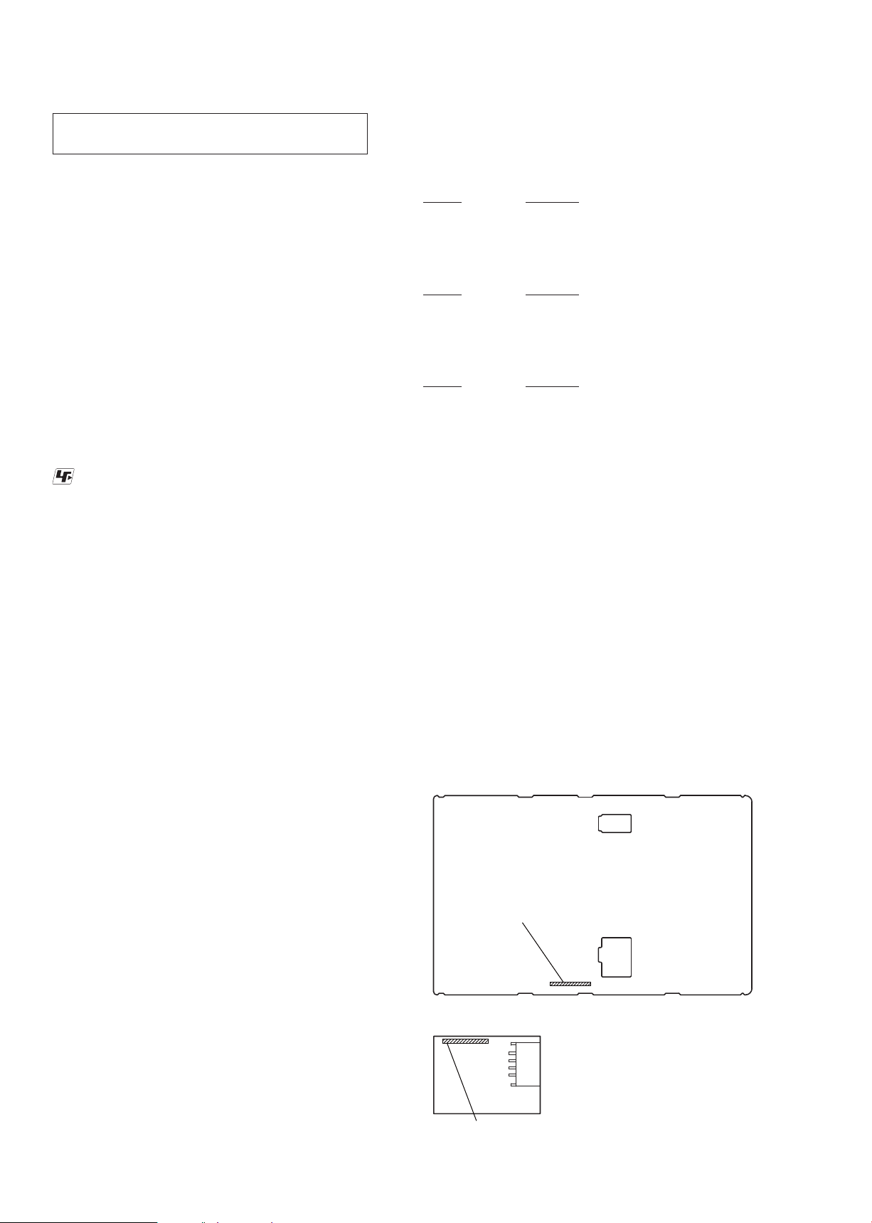
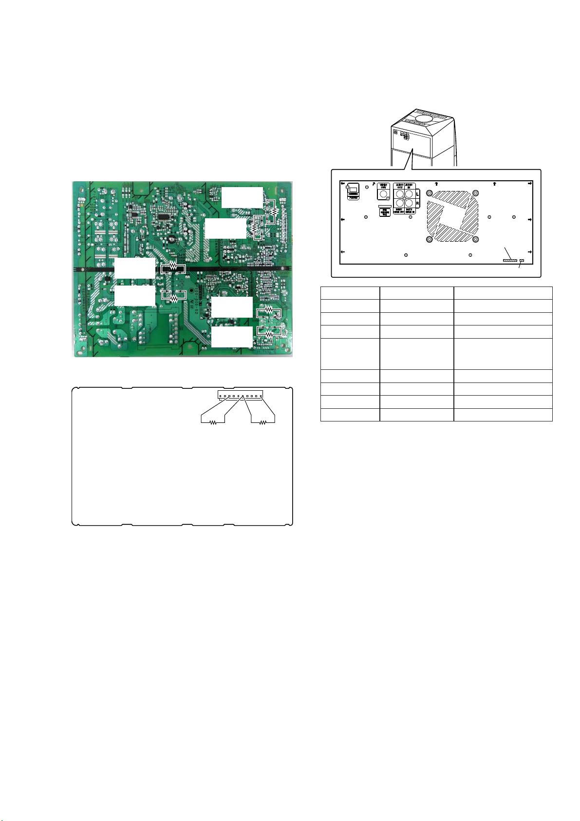
CAPACITOR ELECTRICAL DISCHARGE PROCESSING
When checking the board, the electrical discharge is necessary for
the electric shock prevention.
Connect the resistor to both ends of respective capacitors.
• D-AMP board
CN1000 (pin 6 and 10, pin 6 and 3)
• Switching regulator (SWR1)
C202, C203, C403, C407, C531 and C532
– Switching Regulator (Conductor Side) –
800 :/2 W
(for C403)
800 :/2 W
(for C407)
800 :/2 W
(for C531)
800 :/2 W
(for C532)
– D-AMP Board (Conductor Side) –
800 :/2 W
(for C203)
800 :/2 W
(for C202)
CN1000
110
800 :/2 W
(pin 3 and 6)
800 :/2 W
(pin 6 and 10)
MODEL IDENTIFICATION
Distinguish by Part No. and Destination code on the rear side of
a main unit.
– Rear View –
– Back Panel –
Part No.
Destination code
Part No. Destination code Destination
4-488-633-0[]
4-488-633-1[]
4-488-633-2[]
4-488-633-3[]
4-488-633-4[]
4-488-633-5[]
4-488-633-6[]
4-488-633-7[]
E4/SA2 African and South African
E12 Indian
E51 Chilean and Peruvian
E93
SP6 Singapore and Malaysia
TH1 Thai
MX4 Mexican
E2 120V AC area in E
United Arab Emirates,
Kuwait, Iraq, Kenya,
Tanzania and Nigeria
5
Page 6
MHC-V6D
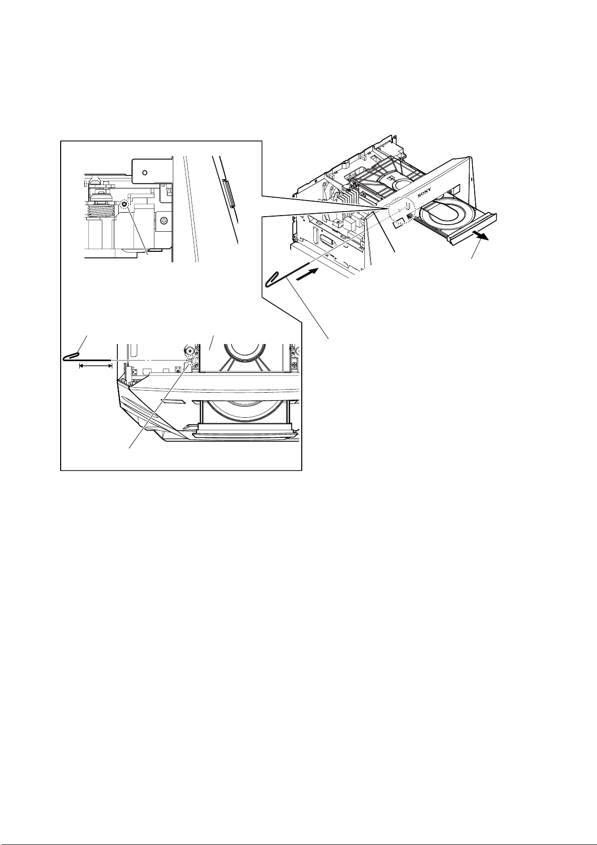
HOW TO OPEN THE TRAY WHEN POWER SWITCH TURN OFF
Note 1: After the side panel and top panel are removed, this work is done.
Note 2: Please prepare the thin wire (clip etc. processed to the length of 8 cm or more).
thin wire (clip etc. )
8 cm or more
hole
hole
– Left view –
2 Draw out the tray.
CD mechanism deck
1 Insert the clip etc. in the hole,
and push the lever in the direction
of the arrow.
tray
– Top view –
6
Page 7
DISASSEMBLY
• This set can be disassembled in the order shown below.
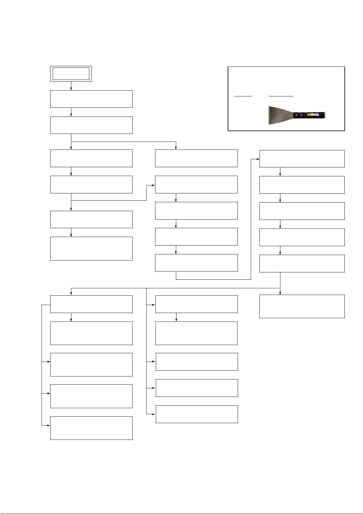
2-1. DISASSEMBLY FLOW
SET
SECTION 2
MHC-V6D
JIG
When disassembling the unit, use the following
jig for speaker removal.
2-2. SIDE L, R PANEL BLOCK
(Page 8)
2-3. TOP PANEL BLOCK
(Page 9)
2-5. LOADING PANEL BLOCK
(Page 11)
2-6. CDM BLOCK
(Page 12)
2-27. FFC HOLDER
(Page 32)
2-28. OPTICAL PICK-UP BLOCK
(CMS-S76RFS7G) (OP1)
(Page 33)
2-4. VOLUME KNOB BLOCK
(Page 10)
2-7. BACK PANEL BLOCK
(Page 13)
2-8. ARAGON BOARD-1
(Page 14)
2-9. ARAGON BOARD-2
(Page 15)
2-10. ARAGON BOARD-3
(Page 16)
Part No. Description
J-2501-238-A JIG FOR SPEAKER REMOVAL
2-11. D-AMP BOARD-1
(Page 17)
2-12. D-AMP BOARD-2
(Page 18)
2-13. SUB CHASSIS
(Page 19)
2-14. FRONT PANEL BLOCK-1
(Page 20)
2-15. FRONT PANEL BLOCK-2
(Page 21)
2-17. FRONT PANEL (SP) BLOCK
(Page 23)
2-18. SPEAKER LED BOARD,
FRONT PANEL (SP) ASSY
(Page 24)
2-19. LOUDSPEAKER (25 cm)
(WOOFER) (SP5)
(Page 25)
2-20. LOUDSPEAKER (10 cm)
(MID: L-CH) (SP1)
(Page 26)
2-21. LOUDSPEAKER (10 cm)
(MID: R-CH) (SP3)
(Page 27)
2-22. FL BOARD BLOCK
(Page 28)
2-23. BLUETOOTH MODULE
(BT1)
(Page 29)
2-24. USB BOARD BLOCK
(Page 30)
2-25. MIC BOARD
(Page 31)
2-26. NFC MODULE (NFC1)
(Page 31)
2-16. SWITCHING REGULATOR
(SWR1)
(Page 22)
7
Page 8

MHC-V6D
Note: Follow the disassembly procedure in the numerical order given.
2-2. SIDE L, R PANEL BLOCK
3 screw cap
2 claw
2 claw
Insert needle-nose pliers behind
1
the second fin, and press
in the direction of the arrow.
Note:
Do not damage screw cap.
2 claw
needle-nose pliers
4 three screws
(BVTP3 u 10)
6 side L panel block
5 Remove the side L panel block
in the direction of the arrow.
4 three screws
(BVTP3 u 10)
2 claw
Insert needle-nose pliers behind
1
the second fin, and press
in the direction of the arrow.
Note:
3 screw cap
Do not damage screw cap.
needle-nose pliers
4 three screws
(BVTP3 u 10)
6 side R panel block
5 Remove the side R panel block
in the direction of the arrow.
4 three screws
(BVTP3 u 10)
8
Page 9
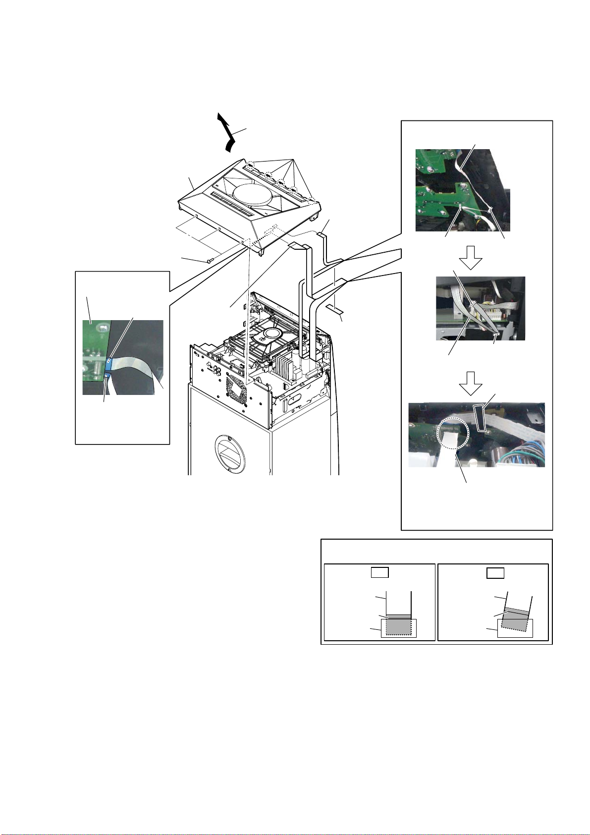
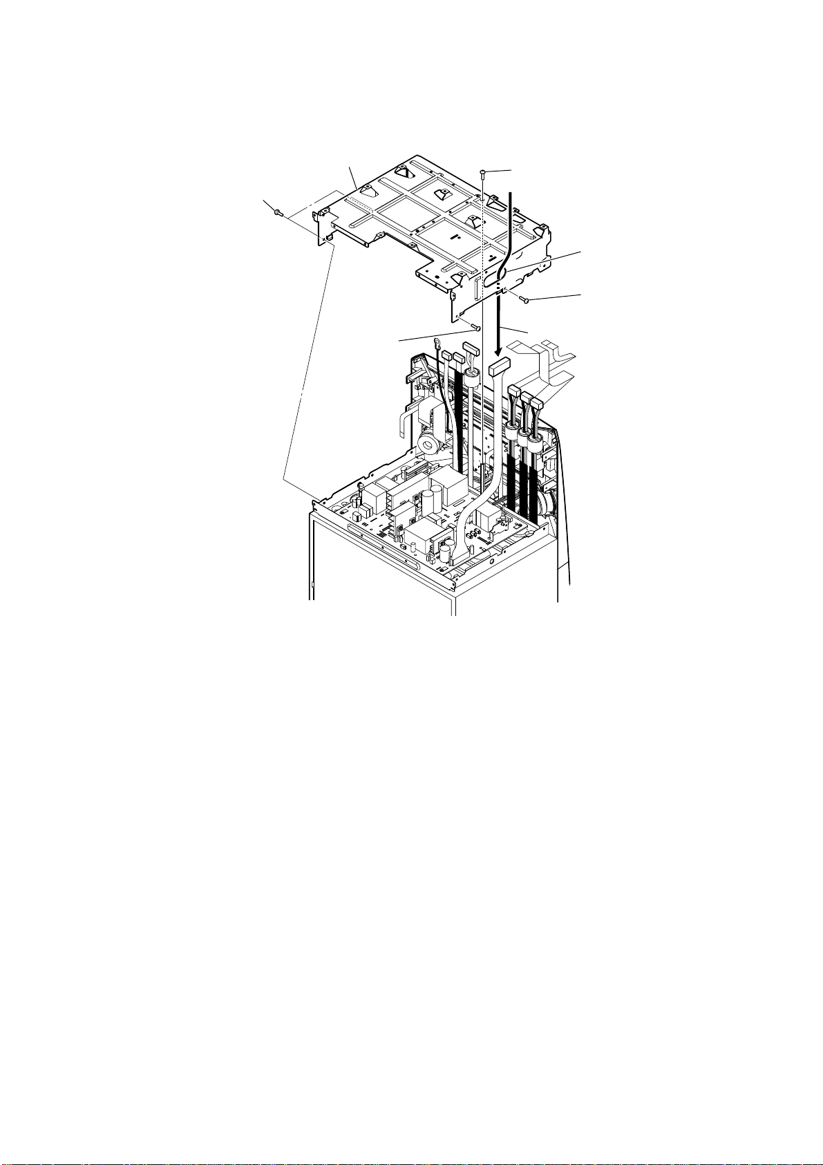
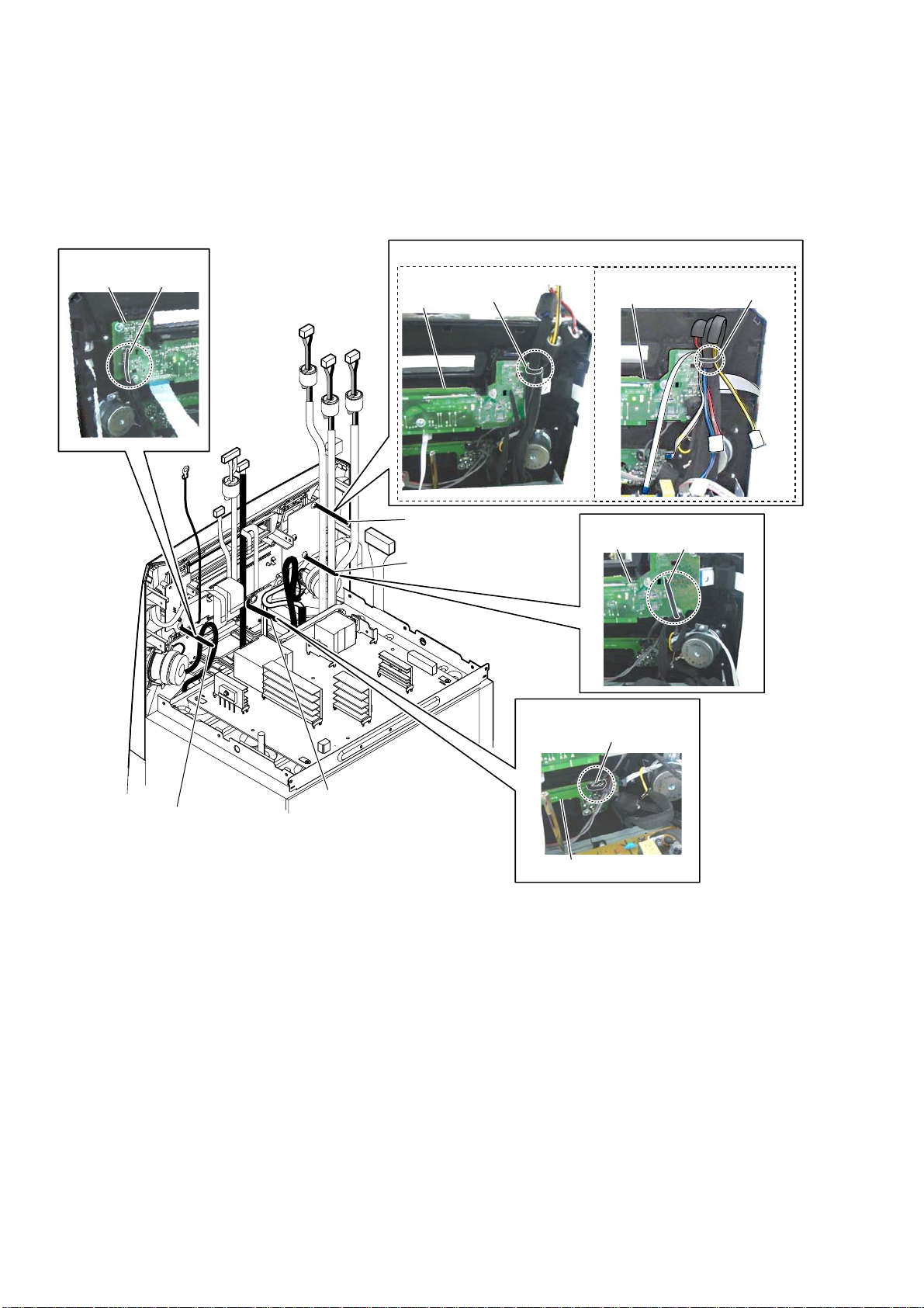
2-3. TOP PANEL BLOCK
MHC-V6D
7 top panel block
1 three screws
(BVTP3 u 10)
WireVHWWLQJ
TOP KEY A board
Terminal face is
below side.
Terminal face is
below side.
–7RSSDQHOEORFN
ERWWRPYLHZ–
6 flexible flat cable
(15P) (CN2100)
3 Remove the top panel block
in the direction of the arrow.
2 five claws
5 flexible flat cable
(4P) (CN2102)
4 cushion (H)
WireVHWWLQJ
flexible flat cable (4P)
guide line
guide line
flexible flat cable (15P)
guide line
guide line
cushion (H)
–7RSUHDUYLHZ–
heat sink
Fix the cushion (H) so that
Note 1:
the flexible flat cable does not
come in contact with the heat sink.
When installing the flexible flat cable, ensure that
Note 2:
the colored line is parallel to the connector after insertion.
OK
Insert straight into the interior.
flexible flat
cable
colored line
connector
flexible flat
cable
colored line
connector
NG
Insert at a slant.
9
Page 10

MHC-V6D
2-4. VOLUME KNOB BLOCK
volume knob block
2
+RZWRLQVWDOOWKHYROXPHNQREEORFN
When installing the volume knob block,
Note 1:
aline the two ribs of volume knob and
the shaft.
hole
top panel block
Push the volume knob block
1
by flat-head screwdriver.
±BRWWRPYLHZ–
–7RSYLHZ–
volume knob block
rib
shaft
TOP KEY A board
–7RSSDQHOEORFNERWWRPYLHZ–
hole
TOP KEY B board
$SSOLFDWLRQSRVLWLRQRIVXQFDOO&)'=
–BRWWRPYLHZ–
rib
shaft
When installing the volume knob block,
Note 2:
please apply suncall (CFD-703Z) to rib
and shaft inside.
10
Page 11

2-5. LOADING PANEL BLOCK
s
MHC-V6D
thin wire (clip etc. )
8 cm or more
hole
– Left view –
hole
CD mechanism deck
tray
– Top view –
2 Draw out the tray.
4 loading panel block
1 Insert the clip etc. in the hole,
and push the lever in the direction
of the arrow.
3 two
claw
11
Page 12
MHC-V6D
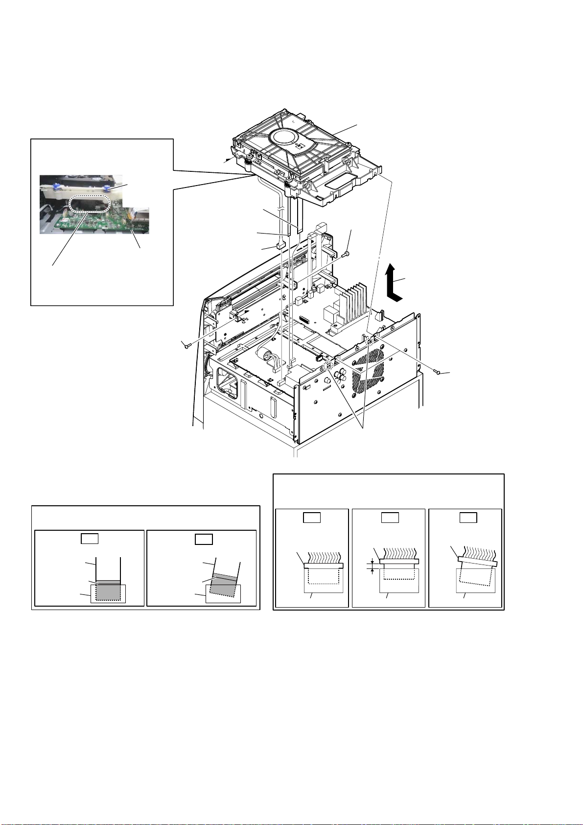
2-6. CDM BLOCK
WireVHWWLQJ
CDM block
ARAGON board
Connect the wire from the CDM
Note 1:
block to the ARAGON board and
place it neatly inside the CDM
block.
6 flexible flat cable
(24P) (CN302)
5 flexible flat cable
(5P) (CN303)
4 connector
(CN401)
7 CDM block
1 screw
(BVTP3 u 10)
3 Remove the CDM block
in the direction of the arrow.
1 screw
(BVTP3 u 10)
When installing the flexible flat cable, ensure that
Note 2:
the colored line is parallel to the connector after insertion.
OK
Insert straight into the interior.
flexible flat
cable
colored line
connector
flexible flat
cable
colored line
connector
NG
Insert at a slant.
2 two hooks
–7RSUHDUYLHZ–
Insert the connector straight into the interior.
Note 3:
There is a possibility that using this device without
the connector correctly installed will damage it.
OK NG NG
Insert straight into
the interior.
connector
connector
Insert only part way.
connector
connector connector
1 two screws
(BVTP3 u 10)
Insert at a slant.
connector
12
Page 13
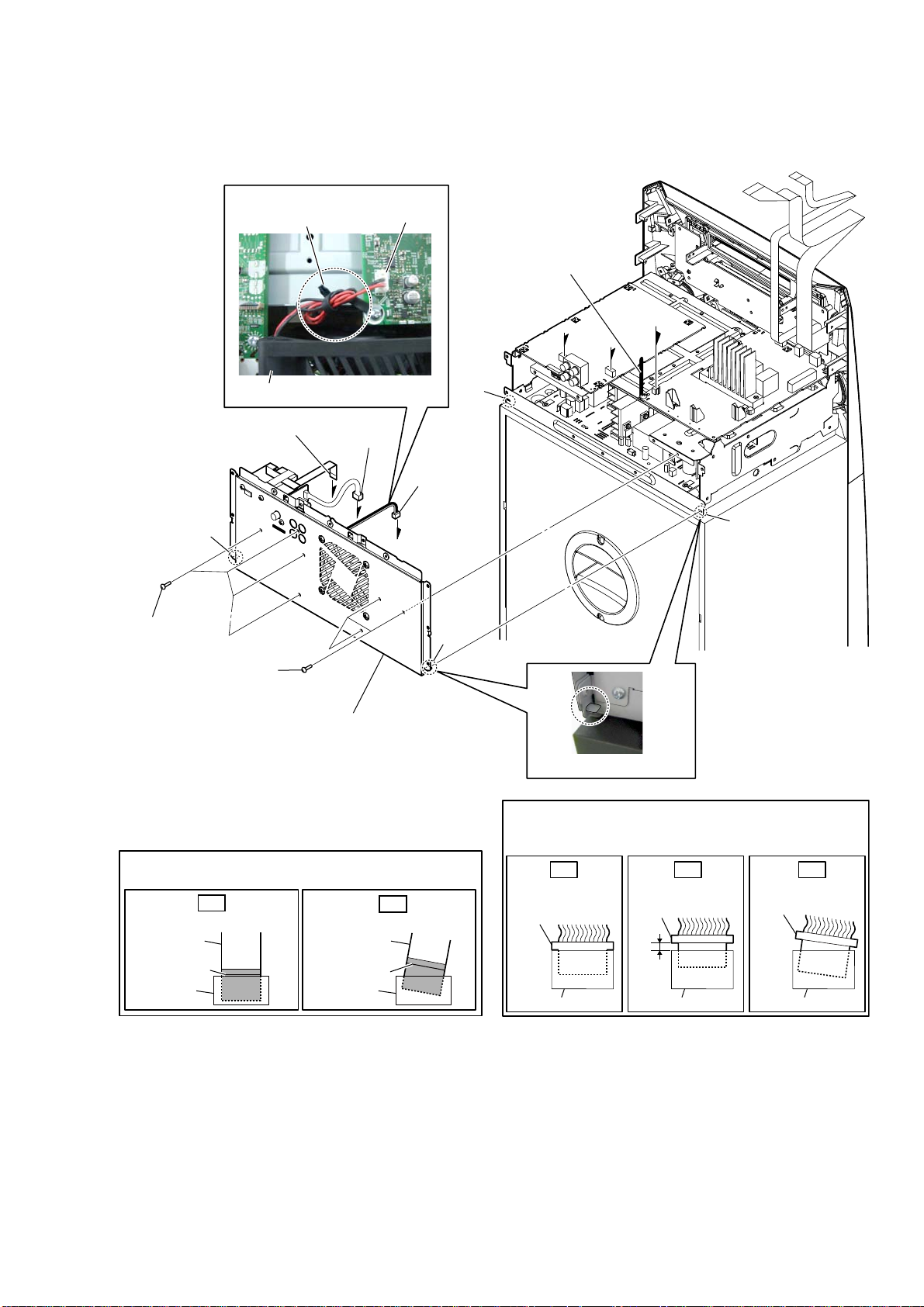
2-7. BACK PANEL BLOCK
'& faQ wire VettiQJ
coating clip
CN1003
1 Remove the DC fan wire
from the coating clip.
C
A
MHC-V6D
B
DC fan
3 flexible flat cable (9P)
(CN851)
hook
5 four screws
(BV/RING)
5 three screws
(BV/RING)
6 back panel block
Note 1:
align two hooks and two holes.
When installing the flexible flat cable, ensure that
Note 2:
the colored line is parallel to the connector after insertion.
OK
Insert straight into the interior.
flexible flat
cable
colored line
connector
4 connector
(CN901)
A
C
When installing the back panel block,
Insert at a slant.
flexible flat
cable
colored line
connector
2 DC fan
connector
(CN1003)
B
NG
hook
hole
hole
– Top rear view –
– Left view –
Insert the connector straight into the interior.
Note 3:
There is a possibility that using this device without
the connector correctly installed will damage it.
OK NG NG
Insert straight into
the interior.
connector
connector
Insert only part way.
connector
connector connector
Insert at a slant.
connector
13
Page 14

MHC-V6D
2-8. ARAGON BOARD-1
• Continued on 2-9 (page 15).
:LUHVHWWLQJ
coating clip
ARAGON board
3 Remove the wire
from the coating clip.
7 flexible flat cable (10P)
(CN102)
4 connector
(CN001)
6 connector
(CN451)
1 cushion (H)
:LUHVHWWLQJ
cushion (H)
2 wire flat type
(19 core)
(CN110)
D-AMP board
ARAGON board
5 connector
(CN601)
When installing the flexible flat cable, ensure that
Note 1:
the colored line is parallel to the connector after insertion.
OK
Insert straight into the interior.
flexible flat
cable
colored line
connector
flexible flat
cable
colored line
connector
NG
Insert at a slant.
–7RSUHDUYLHZ–
Insert the connector straight into the interior.
Note 2:
There is a possibility that using this device without
the connector correctly installed will damage it.
OK NG NG
Insert straight into
the interior.
connector
connector
Insert only part way.
connector
connector connector
Insert at a slant.
connector
14
Page 15

2-9. ARAGON BOARD-2
• Continued on 2-10 (page 16).
MHC-V6D
:LUHVHWWLQJ
cushion (H)
FL board
When installing the flexible flat cable, ensure that
Note:
the colored line is parallel to the connector after insertion.
OK
Insert straight into the interior.
flexible flat
cable
colored line
connector
ARAGON board
2 flexible flat cable (8P)
(CN105)
NG
Insert at a slant.
flexible flat
cable
colored line
connector
1 cushion (H)
3 flexible flat cable (23P)
(CN109)
–7RSUHDUYLHZ–
15
Page 16

MHC-V6D
2-10. ARAGON BOARD-3
• Abbreviation
E93: United Arab Emirates, Kuwait, Iraq, Kenya, Tanzania and Nigeria models
(E93)
3 lug wire
2 coating clip
1 screw
(BV/RING)
1 screw
(BV/RING)
(E93)
4 filament tape
(sub material)
5 sheet
(EMC-absober)
1 three screws
(BV/RING)
6 ARAGON board
– Top rear view –
16
Page 17

2-11. D-AMP BOARD-1
• Continued on 2-12 (page 18).
MHC-V6D
3 connector
(CN1009)
[yellow]
[blue]
4 connector
(CN1008)
[red]
5 connector
(CN1010)
2 connector
(CN1000)
:LUHVHWWLQJ
filament tape
(sub material)
1 two filament tapes
(sub material)
Insert the connector straight into the interior.
Note:
There is a possibility that using this device without
the connector correctly installed will damage it.
OK NG NG
Insert straight into
the interior.
connector
D-AMP board
–/HIWYLHZ–
Insert only part way.
connector
filament tape
(sub material)
Insert at a slant.
connector
– Top rear view –
connector
connector connector
17
Page 18

MHC-V6D
2-12. D-AMP BOARD-2
)OH[LEOHIODWFDEOH3VHWWLQJ
short long
to D-AMP board
CN1006
D-AMP
board
Terminal face is
below side.
terminal face
1 flexible flat cable (19P)
(CN1006)
2 two screws
(BV/RING)
2 two screws
(BV/RING)
2 screw
(BV/RING)
3 coating
clip
4 two screws
(PTPWH2.6 u L)
6 heat sink
7 thermal sheet
2 screw
(BV/RING)
8 D-AMP board
5 bracket
(HS)
–7RSUHDUYLHZ–
When installing the flexible flat cable, ensure that
Note:
the colored line is parallel to the connector after insertion.
OK
Insert straight into the interior.
flexible flat
cable
colored line
connector
flexible flat
cable
colored line
connector
NG
Insert at a slant.
18
Page 19
2-13. SUB CHASSIS
MHC-V6D
2 two screws
(BV/RING)
4 sub chassis
2 screw
(BV/RING)
1 screw
(PSW M3 u 10)
hole
2 screw
(BV/RING)
3 Draw out the wire from hole.
– Top rear view –
19
Page 20
MHC-V6D
2-14. FRONT PANEL BLOCK-1
• Continued on 2-15 (page 21).
• Abbreviation
E93: United
Arab Emirates, Kuwait, Iraq, Kenya, Tanzania and Nigeria models
:LUHVHWWLQJ
FL board
coating clip
:LUHVHWWLQJ
(E93)
FL board
1 Remove the wire from
the coating clip.
3 Remove the wire from
the coating clip.
coating clip
(([FHSW(
FL board
:LUHVHWWLQJ
FL board
coating clip
coating clip
2 Remove the wire from
the coating clip.
:LUHVHWWLQJ
coating clip
4 Remove the wire from
the coating clip.
–7RSUHDUYLHZ–
USB board
20
Page 21

2-15. FRONT PANEL BLOCK-2
MHC-V6D
6 front panel block
5 two bosses
MIC board
4 three screws
(BV/RING)
5 boss
C
2 terminal
(narrow side)
[yellow]
1 terminal
(wide side)
[black]
5 boss
:LUHVHWWLQJ
[yellow]
3 connector
(CN2002)
2 terminal
(wide side)
[black]
Note 1:
over the top of the loudspeaker.
C
Pass the flexible flat cable (4P)
[black]
1 terminal
(narrow side)
[blue]
:LUHVHWWLQJ
[black]
[blue]
– Top rear view –
Insert the connector straight into the interior.
Note 2:
There is a possibility that using this device without
the connector correctly installed will damage it.
OK NG NG
Insert straight into
the interior.
connector
connector
Insert only part way.
connector
connector connector
Insert at a slant.
connector
21
Page 22

MHC-V6D
2-16. SWITCHING REGULATOR (SWR1)
1 Remove the wire from
the coating clip.
:LUHVHWWLQJ
switching regulator
(SWR1)
coating clip
5 three screws
(BV/RING)
7 switching regulator
(SWR1)
5 screw
(BV/RING)
6 coating clip
4 connector
(CN201)
5 two screws
(BV/RING)
2 connector
(CN101)
– Top rear view –
3 connector
(CN401)
5 two screws
(BV/RING)
When you install the connector, please install them correctly.
Note:
There is a possibility that this machine damages when not
correctly installing it.
Insert is straight
to the interior.
connector
OK NG NG
connector
Insert is shallow
connector
connector connector
Insert is incline
connector
22
Page 23
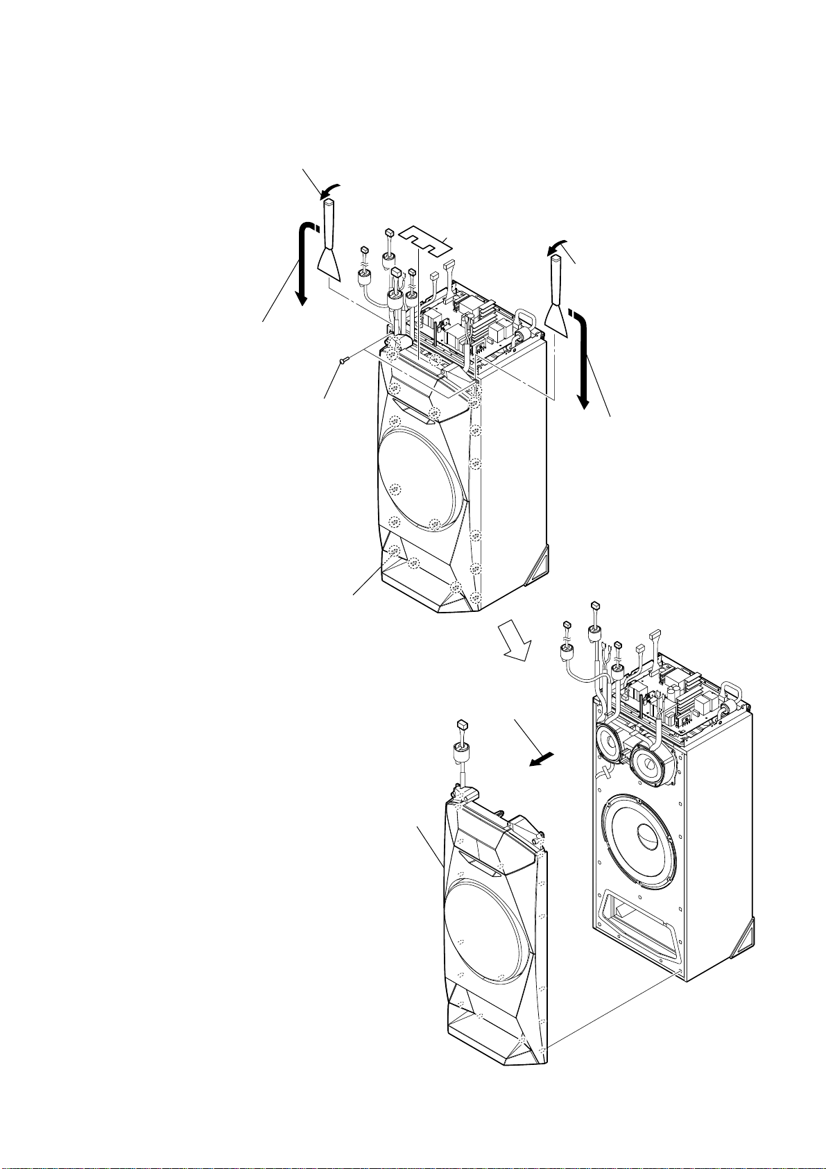
2-17. FRONT PANEL (SP) BLOCK
3 Insert the jig into the space and slowly
remove the front panel (SP) block.
Note: When using a jig, please work
so as not to injure front panel (SP)
block and speaker cabinet.
4 All bosses are removed while moving
jig in the direction of the arrow, and
front panel (SP) block is removed.
2 two tapping screws
(3.5 u 14)
MHC-V6D
1 screw cushion
3 Insert the jig into the space and slowly
remove the front panel (SP) block.
Note: When using a jig, please work
so as not to injure front panel (SP)
block and speaker cabinet.
4 All bosses are removed while moving
jig in the direction of the arrow, and
front panel (SP) block is removed.
total nineteen bosses
6 front panel (SP) block
5 Remove the front panel (SP) block
in the direction of the arrow.
23
Page 24
MHC-V6D
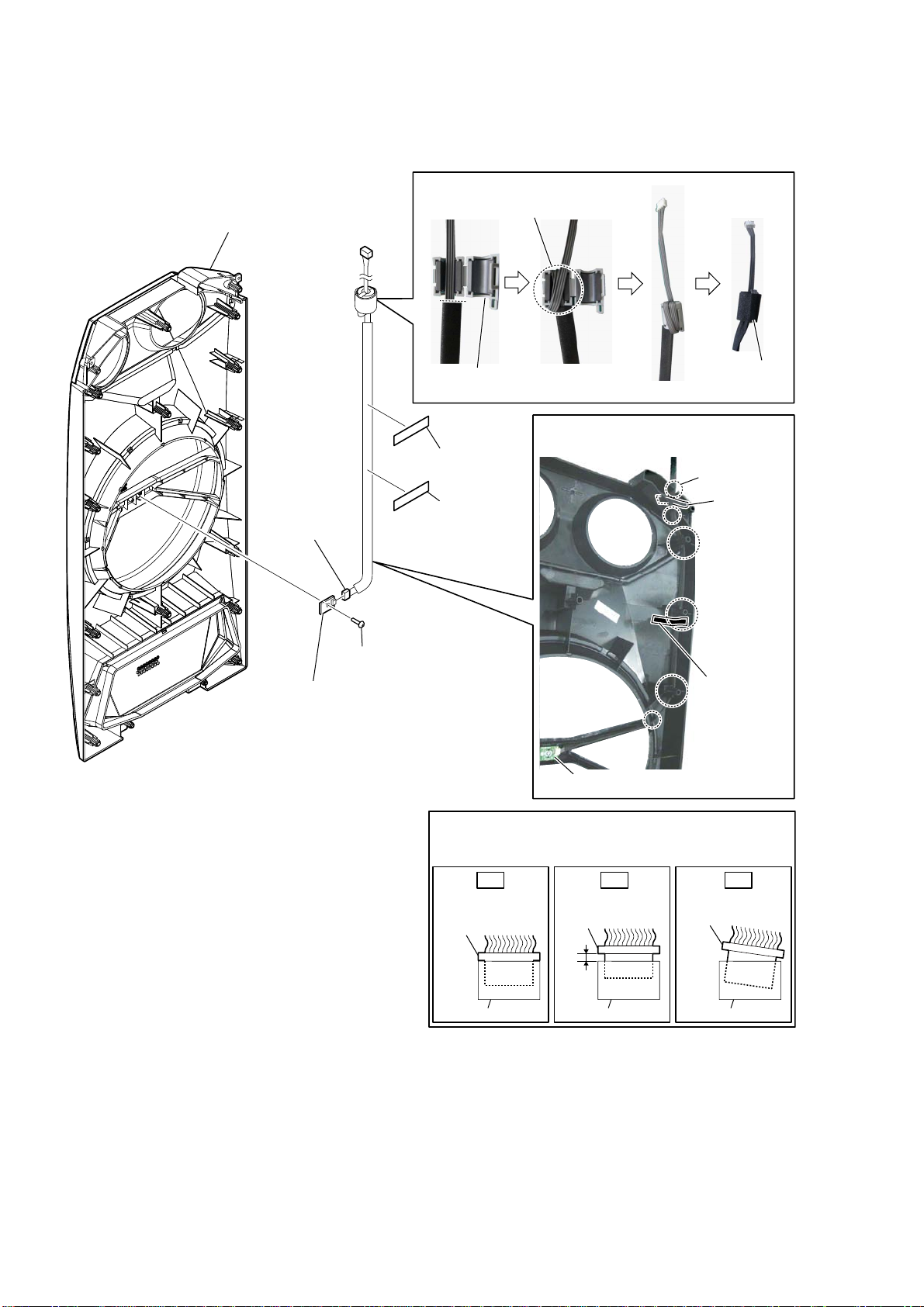
2-18. SPEAKER LED BOARD, FRONT PANEL (SP) ASSY
6OHHYHIHUULWHFODPS)&VHWWLQJ
5 front panel (SP) assy
Wrap twice.
– Front panel (SP) assy rear view –
3 connector
(CN1800)
2 screw
(BVTP3 u 8)
4 SPEAKER LED board
sleeve ferrite clamp
(FC5)
1 cushion (H)
1 cushion (H)
cushion
(E 0.5)
:LUHVHWWLQJ
total six grooves
cushion (H)
cushion (H)
SPEAKER LED board
Insert the connector straight into the interior.
Note:
There is a possibility that using this device without
the connector correctly installed will damage it.
OK NG NG
Insert straight into
the interior.
connector
connector
Insert only part way.
connector
connector connector
Insert at a slant.
connector
24
Page 25
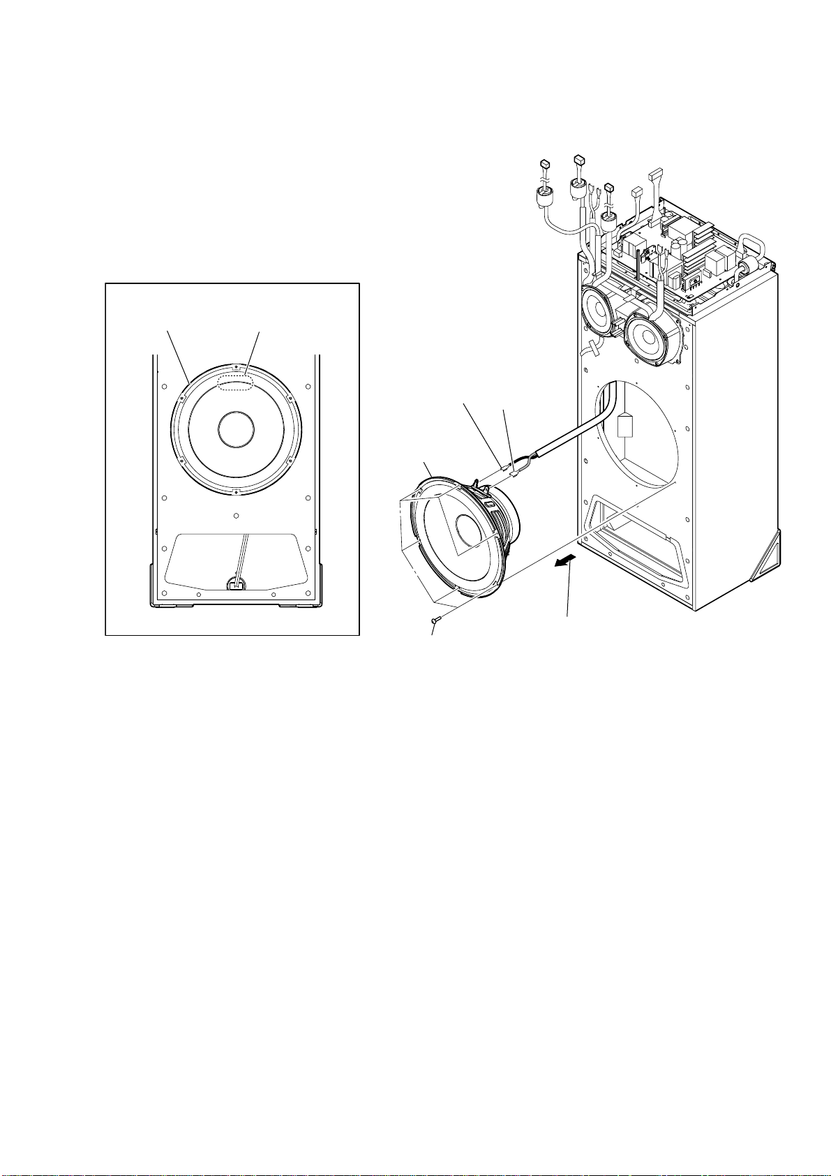
2-19. LOUDSPEAKER (25 cm) (WOOFER) (SP5)
+RZWRLQVWDOOWKHORXGVSHDNHUFP63
MHC-V6D
loudspeaker (25 cm)
(SP5)
terminal position
3 terminal
(narrow side)
[black]
4 loudspeaker
(25 cm) (woofer)
(SP5)
1 six screws
(BVTP4 u 20)
3 terminal
(wide side)
[red]
2 Remove the loudspeaker (25 cm) (SP5)
in the direction of the arrow.
25
Page 26

MHC-V6D
2-20. LOUDSPEAKER (10 cm) (MID: L-CH) (SP1)
+RZWRLQVWDOOWKHORXGVSHDNHUFP63
loudspeaker (10 cm)
(SP1)
:LUHVHWWLQJ
rib
terminal position
rib
:LUHVHWWLQJ
loudspeaker
(10 cm) (SP1)
terminal
(narrow side)
groove
terminal
(wide side)
4 terminal
(narrow side)
4 terminal
(wide side)
speaker cable
1 Remove the speaker cable.
5 loudspeaker (10 cm)
(mid: L-ch) (SP1)
2 four tapping screws
(3.5 u 14)
3 Remove the loudspeaker (10 cm) (SP1)
in the direction of the arrow.
–)URQWOHIWYLHZ–
26
Page 27

2-21. LOUDSPEAKER (10 cm) (MID: R-CH) (SP3)
MHC-V6D
+RZWRLQVWDOOWKHORXGVSHDNHUFP63
loudspeaker (10 cm)
(SP3)
:LUHVHWWLQJ
cushion (H)
:LUHVHWWLQJ
rib
terminal position
wire
rib
1 cushion (H)
:LUHVHWWLQJ
groove
terminal
(narrow side)
terminal
(wide side)
loudspeaker
(10 cm) (SP3)
5 terminal
(narrow side)
5 terminal
(wide side)
wire
2 Remove the wire.
6 loudspeaker (10 cm)
(mid: R-ch) (SP3)
3 four tapping screws
(3.5 u 14)
4 Remove the loudspeaker (10 cm) (SP3)
in the direction of the arrow.
–)URQWOHIWYLHZ–
27
Page 28

MHC-V6D
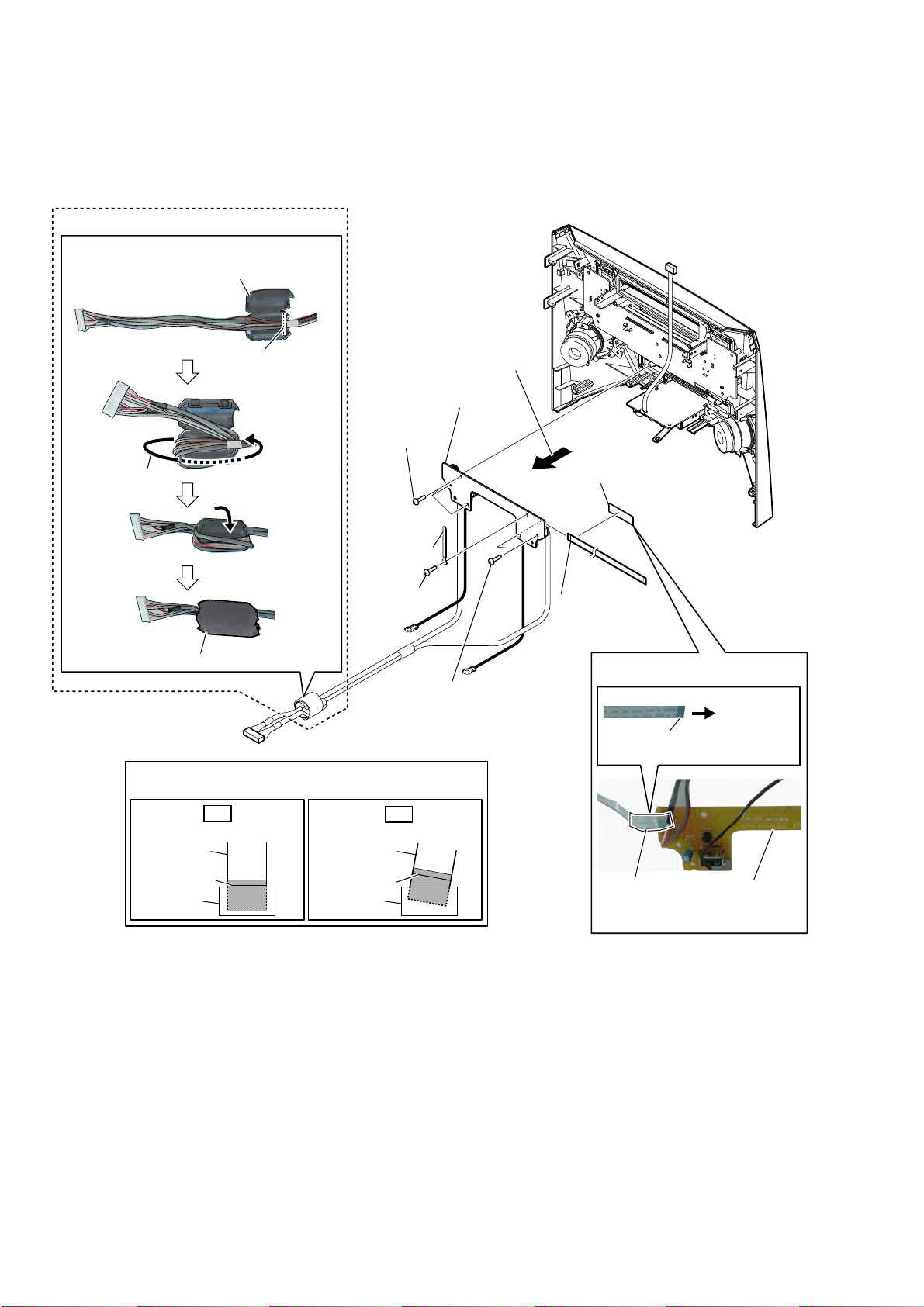
2-22. FL BOARD BLOCK
• Abbreviation
E93: United Arab Emirates, Kuwait, Iraq, Kenya, Tanzania and Nigeria models
:LUHVHWWLQJ
ferrite core
(FC4)
filament tape
(sub material)
terminal face
to FL board
FL board
filament tape
(sub material)
2 three screws
(BVTP3 u 8)
9 FL board
block
2 screw
(BVTP3 u 8)
3 coating clip
8 flexible flat cable (23P)
(CN2000)
3 coating
clip
2 screw
(BVTP3 u 8)
7 filament tape
(sub material)
to FL board
terminal
face
2 screw
(BVTP3 u 8)
6 flexible flat cable
(15P)
(CN2001)
1 cushion (H)
–)URQWSDQHOUHDUYLHZ–
5 filament tape
(sub material)
4 Remove the FL board block
in the direction of the arrow.
)HUULWHFRUH)&VHWWLQJ
flexible flat cable
(
ferrite core (FC4)
)HUULWHFRUH)&VHWWLQJ
flexible flat cable
(23P)
cushion (E 0.5)
cushion (E 0.5)
guide line
ferrite core
(FC1)
ferrite core
(FC1)
3 coating
2 screw
(BVTP3 u 8)
clip
:LUHVHWWLQJ
FL board
When installing the flexible flat cable, ensure that
Note:
the colored line is parallel to the connector after insertion.
Insert straight into the interior.
flexible flat
cable
colored line
connector
cushion (H)
OK
guide line
cushion (E 0.5)
flexible flat
cable
colored line
connector
ferrite core
(FC4)
cushion
(E 0.5)
NG
Insert at a slant.
28
Page 29

2-23. BLUETOOTH MODULE (BT1)
MHC-V6D
WireVeWWiQJ
WireVeWWiQJ
filament tape
(sub material)
bluetooth module
(BT1)
flexible flat cable (10P)
(FFC7)
2 Remove the bluetooth
module (BT1) in the
direction of the arrow.
3 filament tape
(sub material)
to
bluetooth
module
(BT1)
–)rRQWSDQeOreDrYieZ–
1 cishion (H)
5 bluetooth module
(BT1)
4 flexible flat cable (10P)
(FFC7)
+RZWRiQVWDOOWKeEOXeWRRWKPRGXOe%7
cushion (H)
OK NG
Terminal face is
below side.
bluetooth module
(BT1)
When installing the flexible flat cable, ensure that
Note:
the colored line is parallel to the connector after insertion.
OK
Insert straight into the interior.
flexible flat
cable
colored line
connector
terminal face
bluetooth module
(BT1)
NG
Insert at a slant.
flexible flat
cable
colored line
connector
bluetooth module
(BT1)
29
Page 30
MHC-V6D
2-24. USB BOARD BLOCK
• Abbreviation
E93: United Arab Emirates, Kuwait, Iraq, Kenya, Tanzania and Nigeria models
(E93)
Ferrite Fore (F&3) VettinJ
ferrite core (FC3)
– Front panel rear view –
guide line
Wrap once.
cushion (E 0.5)
When installing the flexible flat cable, ensure that
Note:
the colored line is parallel to the connector after insertion.
OK
Insert straight into the interior.
flexible flat
cable
colored line
connector
3 Remove the USB board block
in the direction of the arrow.
6 USB board block
1 three screws
(BVTP3 u 8)
2 coating clip
1 screw
(BVTP3 u 8)
NG
Insert at a slant.
flexible flat
cable
colored line
connector
1 two screws
(BVTP3 u 8)
4 filament tape
(sub material)
5 flexible flat cable
(4P)
(CN2202)
Wire VettinJ
terminal
face
filament tape
(sub material)
to USB board
USB board
30
Page 31

2-25. MIC BOARD
MHC-V6D
– Front panel rear view –
1 knob
(MIC)
2 screw
(BVTP3 u 8)
3 MIC board
2-26. NFC MODULE (NFC1)
WireVeWWiQJ
NFC module block
filament tape
(sub material)
When installing the flexible flat cable, ensure that
Note:
the colored line is parallel to the connector after insertion.
OK
Insert straight into the interior.
flexible flat
cable
colored line
connector
2 Peel off the adhesive sheet (NFC).
5 flexible flat cable (8P)
(FFC6)
4 filament tape
(sub material)
6 Peel off the
tape (NFC).
1 screw
(BVTP3 u 8)
Insert at a slant.
flexible flat
cable
colored line
connector
2 screw
(BVTP3 u 8)
7 NFC holder
NG
3 Remove the NFC module block
in the direction of the arrow.
8 NFC module
(NFC1)
WireVeWWiQJ
NFC module
block
Terminal face is
below side.
NFC module
block
OK
NG
–)rRQWSDQeOreDrYieZ–
to
NFC module
(NFC1)
terminal face
flexible flat cable (8P)
(FFC6)
31
Page 32

MHC-V6D
2-27. FFC HOLDER
1 two screws
(BVTP3 u 8)
1 two screws
(BVTP3 u 8)
2 CD mechanism deck block
FFC holder
6
Note:
check that installed firmly
two bosses and claw.
5 Draw out the flexible flat
cable (24P) from hole.
When installing the FFC holder,
hole
boss
3 cushion (H)
4 Remove the
FFC holder
in the direction
of the arrow.
boss
3DVWLQJSRVLWLRQRIFXVKLRQ+
FFC holder
cushion (H)
–Bottom view –
+RZWRLQVWDOOWKH))&KROGHU
OK NG
32
claw
– CD mechanism deck block bottom view –
There is a gap.
There is no gap.
Page 33

2-28. OPTICAL PICK-UP BLOCK (CMS-S76RFS7G) (OP1)
chuck holder block
2
5 insulator
screw
0 insulator
qa optical pick-up block
(CMS-S76RFS7G)
(OP1)
5 insulator
screw
0 insulator
5 insulator screw
7 connector
9 connector
MHC-V6D
)Oe[iEOeIODWFDEOe3VeWWiQJ
Terminal face is below side.
–7RSYieZ–
5 insulator screw
0 insulator
WireVeWWiQJ
0 insulator
claw
1
Remove the
6
in the direction of the arrow.
3
Draw out the tray.
Note 3:
please refer to “HOW TO OPEN THE TRAY
WHEN POWER SWITCH TURN OFF” on page 6.
When installing the flexible flat cable, ensure that
Note 1:
the colored line is parallel to the connector after insertion.
Insert straight into the interior.
flexible flat
cable
colored line
connector
optical pick-up
three
4
claws
two
1
claws
When you can not draw out the tray,
OK
block
Insert at a slant.
flexible flat
cable
colored line
connector
1
claw
NG
1
claw
1
±BRWWRPYieZ–
8 flexible flat cable (24P)
claw
(FFC1)
Insert the connector straight into the interior.
Note 2:
There is a possibility that using this device without
the connector correctly installed will damage it.
OK NG NG
Insert straight into
the interior.
connector
connector
Insert only part way.
connector
connector connector
Insert at a slant.
connector
33
Page 34

MHC-V6D
SECTION 3
TEST MODE
COLD RESET
It can clears all data including preset data stored in the memory to
initial conditions. Execute this mode when returning the this unit
to the customer.
Procedure:
1. Press the [?/1] button to turn the power on.
2. Press two buttons of the [x] and [PAN] simultaneously for
three seconds.
3. The message “COLD RESET” is displayed on the fl uorescent
indicator tube, then becomes the standby state.
Screen display
USER RESET
It can clears all data including preset data stored in the memory
to initial conditions (Only the connection history information of
Bluetooth is not initialized).
Procedure:
1. Press the [
2. Press two buttons of the [x] and [BASS BAZUCA] simultaneously for three seconds.
3. The message “RESET” is displayed on the fl uorescent indica-
tor tube, then becomes the standby state.
Screen display
AM TUNER STEP CHANGE
It can change AM step interval into 9 kHz or 10 kHz.
Procedure:
1. Press the [
2. Press the [FUNCTION] button to turn the AM function.
3. Press the [
4. While pressing the [> TUNING+] button, press the [
button.
5. The message “9K STEP” or “10K STEP” is displayed on the
fl uorescent indicator tube, and AM step interval changed.
Screen display
] button to turn the power on.
?/1
] button to turn the power on.
?/1
] button to turn the power off.
?/1
?/1
DISC TRAY LOCK MODE
It can be unable to take sample disc out of disc tray in the shop.
Procedure:
1. Press the [?/1] button to turn the power on.
2. Press the [FUNCTION] button to turn the DVD/CD function.
3. Press the [Z] button to open the disc tray and set the disc.
4. Press the [Z] button to close the disc tray.
5. Press two buttons of the [x] and [ENTER] simultaneously for
three seconds.
6. The message “LOCKED” is displayed on the fl uorescent indi-
cator tube and the disc tray is locked.
(Even if pressing the [Z] button, the message “LOCKED” is
displayed on the fl uorescent indicator tube and the disc tray is
locked)
Screen display
Releasing method:
1. Press two buttons of the [x] and [ENTER] simultaneously for
three seconds.
2. The message “UNLOCKED” is displayed on the fl uorescent
indicator tube and the disc tray is unlocked.
Bluetooth PAIRING HISTORY CLEAR
It can clear the Bluetooth pairing history.
Procedure:
1. Press the [?/1] button to turn the power on.
2. Press the [FUNCTION] button to turn the Bluetooth function.
3. Press two buttons of the [x] and [FLANGER] simultaneously
for three seconds.
4. The message “BT HISTORY” → “CLEAR” is displayed on
the fl uorescent indicator tube, and the pairing history of Blue-
tooth is cleared.
Screen display
]
34
or
Page 35

MHC-V6D
Ver. 1.3
VERSION DISPLAY
It can confi rm the SC and MTK version.
Procedure:
1. Press the [?/1] button to turn the power on.
2. Press two buttons of the [ENTER] and [MOVIE/GAME] simultaneously for three seconds.
3. The SC and MTK version is displayed on the fl uorescent indi-
cator tube, and it returns to the display of the normal mode.
SC version
MTK version
(Displayed values in the above fi gure are example)
PANEL TEST
It can confi rm the fl uorescent indicator tube, LEDs, model name,
destination, software version and button.
Procedure:
1. Press the [?/1] button to turn the power on.
2. Press two buttons of the [ENTER] and [FOOTBALL] simultaneously for three seconds.
3. It enters the panel test mode, and all segments on the fl uores-
cent indicator tube and all LEDs light up.
Screen display
ALL USB SEARCH
1 USB PGM
FLDR SHUF
cPLAYcREC
REC
NX
USB A
1
USB B VIDEO PHOTO MUSIC TUNED MONO
NTSC SLEEP PRESETSTEREO
AUTO
%
4. Each time the [ENTER] button is pressed, the screen display is
changed in order as follows.
ALL USB SEARCH
1 USB PGM
FLDR SHUF
cPLAYcREC
REC
NX
USB
1 USB
SHUF
cPLAY
REC
ALL SEARCH
PGM
FLDR
cREC
ALL USB SEARCH
1 USB PGM
FLDR SHUF
cPLAYcREC
REC
NX
USB A%NTSC SLEEP PRESETSTEREO
1
USB B VIDEO PHOTO MUSIC TUNED MONO
1
USB B VIDEO PHOTO MUSIC MONO
USB A NTSC SLEEP PRESETSTEREO
USB A%NTSC SLEEP PRESETSTEREO
1
USB B VIDEO PHOTO MUSIC TUNED MONO
TUNED
All segments and
AUTO
all LEDs turn on
Speaker illumination:
white
Test pattern 1
AUTO
%
Speaker illumination:
red
Test pattern 2
Speaker illumination:
green
All segments and
AUTO
all LEDs turn on
Speaker illumination:
blue
All segments and
all LEDs turn off
Speaker illumination:
off
6. Each time [ +PRESET+] button is pressed, tthe display
changes destination → SC version → MTK version → OPU
version → UI version → PF version → SYS version → CD
version → CMA version → CMB version → ST version →
TA version → TM version this order, and returns to the model
name display.
Model name
SYS version
Destination
CD version
SC version
CMA version
MTK version
CMB version
OPU version
ST version
UI version
TA version
PF version
TM version
(Displayed values in the above fi gure are example)
Destination Display
120V AC area in E model (E2)
African model (E4)
Indian model (E12)
Chilean and Peruvian models (E51)
United Arab Emirates, Kuwait, Iraq, Kenya,
Tanzania and Nigeria models (E93)
South African model (SA2)
Mexican model (MX4)
Singapore and Malaysia models (SP6)
Thai model (TH1)
LATIN
EA3-2
E12
LATIN
EA3-2
EA3-2
MX
ASIA-2
ASIA-2
7. When pressing the [x] button while the each version is displayed, month and day of the software creation is displayed.
When pressing the [
x] button again, the display returns to the
each version display.
Screen display
5. When pressing the [ +PRESET+] button, the model name is
displayed on the fl uorescent indicator tube.
Screen display
(Displayed values in the above fi gure are example)
– Continued on next page –
35
Page 36

MHC-V6D
8. When pressing the [ –PRESET–] button, “K 0 V0” is displayed on the fl uorescent indicator tube.
Screen display
9. Each time a button is pressed, “K 0” value increases. However,
once a button is pressed, it is no longer taken into account.
When pressing the all buttons, “K22” and “OK” are displayed
alternately
Screen display
10. “V0” value increases “V1”, “V2”, “V3” · · · “V8”, “V9”, “V0”
if turn the [VOLUME/DJ CONTROL] knob clockwise, or it
decreases “V9”, “V8”, “V7” · · · “V2”, “V1”, “V0” if turn the
knob counterclockwise.
Releasing method:
Press two buttons of the [ENTER] and [FOOTBALL] simultaneously for three seconds.
DVD COLOR SYSTEM CHANGE
It can change DVD color system into NTSC or PAL.
Procedure:
1. Press the [?/1] button to turn the power on.
2. Press the [FUNCTION] button to turn the DVD/CD function.
3. Press two buttons of the [P AN] and [LED COLOR] simultaneously for three seconds.
4. The message “COLOR NTSC” or “COLOR PAL”is displayed
on the fl uorescent indicator tube, and DVD color system
changed.
Screen display
DVD SERVICE MODE
• This mode let you make diagnosis and adjustment easily by
using the remote commander and the TV. The instructions, diagnostic results, etc. are given on the on-screen display.
• TEST DISC LIST
Be sure to use the DVD disc that matches the signal standards
of your region.
• For CD
Part No. Description
3-702-101-01 DISC (YEDS-18), TEST
4-225-203-01 DISC (PATD-012), TEST
J-2501-307-A DISC (HLX-A1), TEST
• For DVD SL (Single Layer)
Part No. Description
J-6090-069-A DISC (HLX-503), TEST (NTSC)
J-6090-088-A DISC (HLX-504), TEST (NTSC)
J-6090-077-A DISC (HLX-506), TEST (PAL)
• For DVD DL (Double Layer)
Part No. Description
J-6090-071-A DISC (HLX-501), TEST (NTSC)
J-6090-089-A DISC (HLX-505), TEST (NTSC)
J-6090-078-A DISC (HLX-507), TEST (PAL)
• Procedure to enter to DVD Service Mode:
1. Press the [
] button to turn the power on.
?/1
2. Press the [FUNCTION] button to turn the DVD/CD function.
3. Press two buttons of the [WAH] and [LED COLOR] simultaneously for three seconds.
4. The message “SERVICE IN” appears on the fl uorescent in-
dicator tube and the Top Menu of Remocon Diagnosis Menu
appears on the on-screen display on the TV. The model name,
main unit’s micom version information (IF-con) and DVD
fi rmware version information (Syscon) are displayed at the
bottom of the on-screen display.
Remocon Diagnosis Menu
0. External Chip Check
1. Servo Parameter Check
2. Drive Manual Operation
3. Emergency History
4. Version Information
Model Name : V6D_GA
IF
–
con : Ver. 01.02 (0000)
Syscon : Ver. 1.020
or
5. When the “NTSC” mark is lights up, DVD color system is
NTSC.
When the “NTSC” mark is turns off, DVD color system is
PAL.
Screen display
NTSC
MUSIC
(Displayed characters in the above fi gure are example)
36
5. To execute each function, press its number by using numeric
button on the remote commander.
Releasing method:
Press the [
] button to turn the power off.
?/1
Page 37

MHC-V6D
• Execute IOP Measurement
In order to execute IOP measurement, the following standard
procedures must be followed.
1. From the Top Menu of Remocon Diagnosis Menu, select “2.
Drive Manual Operation” by pressing the [2] button on the
remote commander. The following screen appears on the onscreen display.
Drive Manual Operation
1. Servo Control
2. Track/Layer Jump
3. Manual Adjustment
4. Tray Aging Mode
5. MIRR time Adjust
0. Return to Top Menu
2. Select “3. Manual Adjustment” by pressing the [3] button on
the remote commander. The following screen appears on the
on-screen display.
Manual Adjust
1. Track Balance Adjust:
2. Track Gain Adjust:
3. Focus Balance Adjust:
4. Focus Gain Adjust:
5. Eq Boost Adjust:
6. Iop:
7. TRV. Level:
8. S curve(FE) Level:
9. RFL(PI) Level:
0. MIRR Time:
O o
Change Value
[RETURN] Return to previous menu
3. Select “6. Iop:” by pressing the [6] button on the remote commander.
4. Wait until a hexadecimal number appears in the on-screen display as below:
Manual Adjust
1. Track Balance Adjust:
2. Track Gain Adjust:
3. Focus Balance Adjust:
4. Focus Gain Adjust:
5. Eq Boost Adjust:
6. Iop: ED
7. TRV. Level:
8. S curve(FE) Level:
9. RFL(PI) Level:
0. MIRR Time:
O o
Change Value
[RETURN] Return to previous menu
(Displayed values in the above fi gure are example)
5. Convert data from hexadecimal to decimal by using conversion table.
6. Please fi nd the label on the rear of the BU (Base Unit).
The default IOP value is written in the label.
7. Subtract between these two values.
8. If the remainder is smaller than 93 (decimal), then it is OK.
However if the value is higher than 93, then the BU is defec-
tive and need to be change.
9. Press the [RETURN] button on the remote commander to return to previous menu.
10. Press the [0] button on the remote commander to return to the
Top Menu of Remocon Diagnosis Menu.
11. Press the [
] button to turn the power off.
?/1
• Check Emergency History
To check the emergency history, please follow the following
procedure.
1. From the Top Menu of Remocon Diagnosis Menu, select “3.
Emergency History” by pressing the [3] button on the remote
commander. The following screen appears on the on-screen
display.
Emg. History Check
Laser Hours CD 999h 59min
01. 01 05 04 04
00 00 00 00
02. 02 02 01 01 00 A9 4B 00
00 00 00 00
[Next]Next Page [Prev]Prev Page
[0] Return to Top Menu
DVD 999h 59min
00 92 46 00
00 00 23 45
00 00 23 45
(Displayed values in the above fi gure are example)
2. Y ou can check the total time when the laser is turned on during
playback of DVD and CD from the above menu. The maximum time, which can be displayed are 999h 59min.
3. You can check the error code of latest 10 emergency history
from the above menu. To view the previous or next page of
emergency history, press the [.] button or [>] button
on the remote commander. The error code consists of “Error
Code”, “Parameter of error code” and “Time of error code”.
• Error Code
Example of Error code
01. 01 05 04 04 00 92 46 00
00 00 00 00
00 00 23 45
The meaning of error code is as below:
01: Communication error (No reply from syscon)
02: Syscon hung up
03: Power OFF request when syscon hung up
19: Thermal shutdown
24: MoveSledHome error
25: Mechanical move error (5 Changer)
26: Mechanical move stack error
30: DC motor adjustment error
31: DPD offset adjustment error
32: TE balance adjustment error
33: TE sensor adjustment error
34: TE loop gain adjustment error
35: FE loop gain adjustment error
36: Bad jitter after adjustment
40: Focus NG
42: Focus layer jump NG
51: Spindle stop error
52: Open kick spindle error
60: Focus on error
61: Seek fail error
62: Read Q data/ID error
70: Lead in data read fail
71: TOC read time out (CD)
80: Can’t buffering
81: Unknown media type
37
Page 38

MHC-V6D
• Parameter of error code
This is the detail of error code.
Example of Error code
01. 01 05 04 04 00 92 46 00
00 00 00 00
00 00 23 45
• Time of error code
This is the laser time when an error occurred.
Example of Error code
01. 01 05 04 04 00 92 46 00
00 00 00 00
00 00 23 45
To clear the Laser Hours
While pressing the [SHIFT] button on the remote commander,
press the [ DISPLAY] button on the remote commander and then
press the [CLEAR] button on the remote commander. The data for
both CD and DVD data are reset.
Emg. History Check
Laser Hours CD 0h 0min
01. 01 05 04 04
00 00 00 00
02. 02 02 01 01 00 A9 4B 00
00 00 00 00
[Next]Next Page [Prev]Prev Page
[0] Return to Top Menu
DVD 0h 0min
00 92 46 00
00 00 23 45
00 00 23 45
To clear the Emergency History
Press the [DVD TOP MENU] button on the remote commander.
And then while pressing the [SHIFT] button on the remote commander, press the [CLEAR] button on the remote commander.
The error code for all emergency history would be reset.
To clear the Initialize Setup Data
Press the [DVD/TUNER MENU] button on the remote commander. And then while pressing the [SHIFT] button on the remote commander, press the [CLEAR] button on the remote commander.
Emg. History Check
Laser Hours CD 999h 59min
DVD 999h 59min
Initialiez setup data ...
[Next]Next Page [Prev]Prev Page
[0] Return to Top Menu
To return to the Top Menu of Remocon Diagnosis Menu
Press the [0] button on the remote commander.
• Check Version Information
To check the version information, please follow the following
procedure.
1. From the Top Menu of Remocon Diagnosis Menu, select “4.
Version information” by pressing the [4] button on the remote
commander. The following screen appears on the on-screen
display.
Version Information
Firm(Main): Ver. x.xxx
Firm(Sub): xx.xx
RISC: xxxxxx
8032: xxxxxx
Audio DSP: xx.xx.xx.xx
Servo DSP: xx.xx.xx.xx
[0] Return to Top Menu
Emg. History Check
Laser Hours CD 999h 59min
01. 00 00 00 00
00 00 00 00
02. 00 00 00 00 00 00 00 00
00 00 00 00
[Next]Next Page [Prev]Prev Page
[0] Return to Top Menu
DVD 999h 59min
00 00 00 00
00 00 00 00
00 00 00 00
To return to the Top Menu of Remocon Diagnosis Menu, press
the [0] button on the remote commander.
38
Page 39

SECTION 4
ELECTRICAL CHECK
MHC-V6D
TUNER SECTION
FM TUNE LEVEL CHECK
generator
Procedure:
1. Press the [?/1] button to turn the power on.
2. Input the following signal from signal generator to FM antenna
input directly.
Carrier frequency : A = 87.5 MHz, B = 98 MHz, C = 108 MHz
Deviation : 75 kHz
Modulation : 1 kHz
ANT input : 35 dBu (EMF)
Note: Use 75 ohm coaxial cable to connect signal generator and the unit.
You cannot use video cable for checking.
Use signal generator whose output impedance is 75 ohm.
3. Set to FM tuner function and tune A, B and C signals.
4. Confi rm “TUNED” is lit on the display for A, B and C signals.
When the selected station signal is received in good condition,
“TUNED” is displayed.
signal
0 dB = 1 V
unit
MHC-V6D
3939
Page 40

MHC-V6D
SECTION 5
DIAGRAMS
5-1. BLOCK DIAGRAM - CD/USB Section -
OPTICAL PICK-UP BLOCK
(CMS-S76RFS7G)
RF
VOA/A
VOB/B
VOC/C
VOD/D
VOE/E+G
VOF/F+H
VC
PD
LD (780)
LD (650)
MSW
VR (780)
VR (650)
NC (LIMIT)
AUTOMATIC POWER
CONTROL (FOR CD)
Q402
AUTOMATIC POWER
CONTROL (FOR DVD)
Q401
RF AMP, SERVO/AUDIO PROCESSOR
123 R FIP
1 RF_C
128 R F_B
127 R F_A
2 RF_D
4 RF_F
3 RF_E
10 V20
13 MDI1
14 LDO1
15 LDO2
23 MSW
19 CD_VR
20 DVD_VR
44 LIMITSW
IC301
ASDATA0, MTK-BCK,
MTK-LRCK, MTK-MCK
J2400
VIDEO OUT
3
D+
2
D–
ADIN
CN2204
A
PLAY
5V 500mV
>001B
(Page 41)
>002B
(Page 41)
X301
27MHz
ASDATA0
MTK-BCK
MTK-LRCK
MTK-MCK
VIDEO AMP
IC901
4VIN
USB HUB CONTROLLER
IC451
24 DP0
23 DM0
2VOUT
3VSAG
1POWER SAVE
2DP1
1DM1
118ASDATA0
113ABCK
117ALRCK
112ACLK
106ADIN
100CVBS
8XTALO
7XTALI
25USB_DP
24USB_DM
SP+
SP–
SL+
SL–
TRK+
TRK–
FCS+
FCS–
FOCUS/TRACKING COIL DRIVE,
SPINDLE/SLED/LOADING MOTOR DRIVE
11 VOSL+
12 VOSL–
17 VOLD+
18 VOLD–
16 VOTK–
15 VOTK+
14 VOFC+
13 VOFC–
IC401
4VINSL+
23VINLD
26VINTK
1VINFC
28MUTE
27BIAS
17 DMO
18 FMO
21 TRO
22 FOO
45 MUTE
11 V14/VREF0
X451
SERIAL FLASH
IC302
2
31SF_DO
32SF_DI
SO
5
SI
6
SCK33SF_CK
1
_CS30SF_CS#
12MHz
8X2
4DP2
7X1
3DM2
RESET
14
3
2
CN2203
D+
B
REC/PLAY
D–
5V 500mV
SIGNAL PATH
: DISC PLAY
SD-RAM
IC306
RD0 – RD15
RA0 – RA11
85BA0
86BA1
82CAS#
83RAS#
47SDA
48SCL
IFSDI
IFSDO
IFSCK
IFCS#
IFBSY
40
35
34
PRST#
42
41
38
DG0, DQ1 – DQ15
A0 – A9,
A10/AP, A11
20
BA0
21
BA1
38
CLK72RCLK
16
WE80RWE#
17
CAS
18
RAS
15
LDQM61DQM0
39
UDQM70DQM1
5
SDA
6
SCL
7
WE46EEWP
EEPROM
IC304
: AUDIO
: USB
: VIDEO
MHC-V6D
MS-476 BOARD
TRAY-OUT
LOAD+
LOAD–
TRAY-IN
10 VOTR+
9VOTR–
22
20
17
19
16
15
MTK-SDI
MTK-CLK
MTK-SDO
6FWD
7REV
122 CD-MOTOR+
124 CD-MOTOR–
4 CDM-LOAD-SW
3 CDM-UNLOAD-SW
MTK-BUSY
MTK-XIFCS
MTK-RESET
SYSTEM CONTROLLER
IC101 (1/4)
13
HUB-RESET
2
VIDEO-MUTE
4040
Page 41

5-2. BLOCK DIAGRAM - MAIN Section -
ASDATA0, MTK-BCK,
MTK-LRCK, MTK-MCK
>001B
(Page 40)
TU1
TUNER1AM3RZ ASSY
(TUNER UNIT)
AUDIO L/LRCK
ANTENNA
FM/AM
>002B
AUDIO R/BCK
DA (for IIC)
CK (for IIC)
CE (p con)
IIC/RDSI
ADIN
(Page 40)
J2300
MIC 1
J2301
MIC 2
R-ch is omitted due to same as L-ch.
SIGNAL PATH
: DISC PLAY
: TUNER
: AUDIO
: Bluetooth
: MIC
J601 (1/2)
AUDIO IN
PARTY CHAIN IN
L
R
R-CH
R-CH
ST-DATA
ST-DATA
128
ST-CLK
ST-CE
ST-RDS
+
ST-CLK
127
ST-CLK
ST-DATA
LINK
DETECT
Q605, 607
ST-CE
ST-RDS
59
114
115
ST-CE
ST-RDS
LINK-DET
ANALOG AUDIO
SELECTOR
IC605
15 X2
11 X3
12 X0
AB
10 9
R-CH
INVERTER
Q604
41
ANALOG-ASEL
13X
42
ANALOG-BSEL
ANALOG AUDIO
SELECTOR
IC602
1Y0
4Y3
AB
10 9
INVERTER
Q611
51
176
LINK-OUT-A
MIC AMP
IC2300
MIC LEVEL
LINK-OUT-B
VR2318
3Y
ASDATA0
MTK-BCK
MTK-LRCK
MTK-MCK
MTK-BCK
MTK-LRCK
GAIN
CONTROL
Q2300, 2301
LINE AMP
IC603
LINE AMP
IC601
R-CH
R-CH
D2300
MUTING
Q602
MUTING
CONTROL
Q606
94
/LINK-MUTE
A/D CONVERTER
IC606
13
VINL
14
VINR
8
BCK
7
LRCK
6
SCKI
DOUT
LINK SET
CONTROL
Q603
175
LINK-SET
DIGITAL AUDIO SELECTOR
1A
2B
9
A/D CONVERTER
IC609
13 9
VINL DOUT
14
VINR
BCK
LRCK
SCKI
D/A CONVERTER
IC604
2 7
DATA VOUTL
BCK
LRCK
SCK
J601 (2/2)
L
R
IC607
5Y
SEL
6
8
7
6
8VOUTR
R-CH
1
3
16
AUDIO OUT
PARTY CHAIN OUT
SAMPLE RATE CONVERTER
4SDIN
5BCKI
2 RCKI
111
ANALOG-CSEL/SD_D1_0
IC610
RST
13
1
SRC-RST0
23SDOUT
25BCKO
24LRCKO6 LRCKI
14
26
24
SSI3_BCKO
SSI3_LRCKO
AUDIO_CLK_OUT
BT1
Bluetooth MODULE
BT-RXD
BT-TXD
BT-RESET
29
30
SSI0_BCKO
SSI0_LRCKO
ARAGON-BCK0
ARAGON-LRCK0
28 SSI3_DI
BUS BUFFER
IC102 (1/2)
SERIAL FLASH
IC106
2
SO/SIO1
5
SI/SIO0
3
WP/SIO2 166 Q-Flash-SIO2
HOLD/SIO3 167 Q-Flash-SIO3
EEPROM
IC105
SYSTEM CONTROLLER
IC101 (2/4)
7
6
SCLK 168 Q-Flash-CLK
1
CS 169 Q-Flash-CS
2
SDA
6
SCL
65 BT-RXD (MD-CLK)
133 BT-TXD
55 SSI1_DI
173 MIC-DETECT
27 SSI3_DOUT3
172 Q-Flash-SIO1
170 Q-Flash-SIO0
126 C P-DATA
125 C P-CLK
5 BT-RESET
MHC-V6D
DOUT0
32SSI0_DO
DOUT2
33SSI2_DO
ARAGON-MCK
71XTAL
70EXTAL
68RTC-X2
67RTC-X1
92AUDIO-X2
91AUDIO-X1
X102
13.333MHz
X101
32.768kHz
X103
12.288MHz
(Page 42)
>003B
DOUT0, DOUT2,
ARAGON-MCK,
ARAGON-BCK0,
ARAGON-LRCK0
RESET
>004B
(Page 43)
MHC-V6D
4141
Page 42

MHC-V6D
5-3. BLOCK DIAGRAM - AMP Section -
D/A CONVERTER
(Page 41)
>003B
DOUT0, DOUT2,
ARAGON-MCK,
ARAGON-BCK0,
ARAGON-LRCK0
DOUT0
ARAGON-BCK0
ARAGON-LRCK0
ARAGON-MCK
2 7
1
3
16
IC611
DATA VOUTL
BCK
LRCK
SCK
AUDIO AMP
IC1011
3 14
DAC LPF
8VOUTR
IC612
MUTING
Q1035
MUTING
Q1033
PRE AMP
IC1015
IN– HO
AUDIO AMP
IC1009
3 14
IN– HO
11LO
13VS5CSD
11LO
BOOSTER
Q1028
BOOSTER
Q1030
BOOSTER
Q1023
BOOSTER
Q1025
D1061
SP1
(MID)
(L-CH)
SP2
(TWEETER)
(L-CH)
SP3
(MID)
(R-CH)
SP4
(TWEETER)
(R-CH)
DOUT2
ARAGON-BCK0
ARAGON-LRCK0
ARAGON-MCK
RESET
SWITCH
Q1008
D/A CONVERTER
IC615
2
DATA
1
BCK
3
LRCK
16
SCK
SHUTDOWN
SWITCH
Q1058
13VS5CSD
AUDIO AMP
IC1012
8VOUTR
DAC LPF
IC616
POWER ON/OFF
SWITCH
Q1031
POWER ON/OFF
SWITCH
Q1026
POWER ON/OFF
SWITCH
Q1036
MUTING
Q1042
MUTING
CONTROL
Q109
PRE AMP
IC1016
CLOCK
BAND PASS FILTER
IC1003
3 14
IN– HO
11LO
13VS5CSD
BOOSTER
Q1032
BOOSTER
Q1034
FAN MOTOR
DRIVE
Q1059, 1062,
Q1065, 1069
OVER LAOD
DETECT
Q1037
OVER LAOD
DETECT
Q1027
DC DETECT
Q1060
SP5
(SUBWOOFER)
M1
MM
(FAN)
MHC-V6D
120
/AMP-RESET
131
/AMP-SD
96
/LINE-MUTE-FR
/AMP-RESET
>005B
(Page 43)
136
AMP-CLK-FR
SYSTEM CONTROLLER
IC101 (3/4)
132
/DC-DET
SIGNAL PATH
: AUDIO
4242
Page 43

5-4. BLOCK DIAGRAM - PANEL/POWER SUPPLY Section -
SYSTEM CONTROLLER
IC101 (4/4)
THERMISTOR-PROTECT 78
135
SIRCS
SPM-AMBIENT-TEMP 80
40 FL-SOUT
35 FL-CLK
134 FL-BK
45 POWER-KEY
84 AD-KEY0
85 AD-KEY1
83
MASTER-VOLUME
48 RGB-SOUT
137 RGB-SCLK
118 RGB-PWM-CLK
RGB-TRANS-LED/
113
SD_CD_0
D2100
DJ EFFECT
FLANGER
D2101
DJ EFFECT
ISOLATOR
D2102
DJ EFFECT
WAH
D2103
DJ EFFECT
PAN
D2108
BASS BAZUCA
6OUT1
13 OUT8
7OUT2
14 OUT9
10 OUT5
S2000, 2100, 2102,
S2107, 2109, 2111,
S2113, 2200, 2201
(TOP AND FRONT PANEL KEYS)
S2103, 2105, 2114, 2115,
S2150 – 2157
(TOP PANEL KEYS)
LED DRIVER
IC2002
2SIN
3SCK
21PWMCLK
4TRANS
8OUT3
15OUT10
REMOTE CONTROL
RECEIVER
IC2000
ND2000
FLUORESCENT
INDICATOR TUBE
CLK
STB
S2001
I / 1
EN2100
VOLUME/
DJ CONTROL
(ILLUMINATION)
(ILLUMINATION)
DIN
SW
D2104
D2105
ROTARY
ENCODER
PCONT-DAMP
130/PS-PROTECT
79SPM-C-MON
117
165C-CONT
8BT-ON
76RES
TEMPERATURE DETECT
Q1066, 1067
TH571
TEMPERATURE
MONITOR
Q574 – 576
D1024
CHARGING
CONTROL
Q571, 572
RESET SIGNAL
GENERATOR
IC103
D1034
TH1008
TH1009
TH1010
(FOR IC301)
DVDD5V
+3.3V
D+3.3V
E+3.3V
FE+5V
BT+3.3V
+1.2V
FE_3.3V
E+1.18V
+3.3V
REGULATOR
IC305
+1.2V
REGULATOR
IC303
POWER SUPPLY
PROTECT
Q1000, 1002 – 1004, 1007
B+ SWITCH
Q008, 009
B+ SWITCH
Q006, 007
B+ SWITCH
Q103, 104
B+ SWITCH
Q005
D1007
FOR
FLUORESCENT
INDICATOR TUBE
GVDD
–5V
–18V
+5V
+18V
VIN
VDD
AVDD+5V
AVDD+9V
SW+13V
MHC-V6D
REGULATOR
IC1002
–5V
REGULATOR
IC1001
+5V
REGULATOR
IC1000
DC/DC
VH
F+
CONVERTER
D2006, 2011, Q2004
+5V
REGULATOR
IC006
DC/DC CONVERTER
IC002
14 SW2
3 SW1
16VIN2
1VIN1
REGULATOR
Q1005
REGULATOR
Q1006
B+ SWITCH
Q2002, 2003
+6V
REGULATOR
IC2003
+9V
REGULATOR
IC004
POWER
CONTROL
Q012
B+ SWITCH
Q011
–VH
+VH
B+ SWITCH
Q003, 004
13V
–46V
–VL
+VL
–VH
+VH
MAIN-ON
SWR1
SWITCHING
REGULATOR
MHC-V6D
D2109
CONNECTION
PAIRING
BLUETOOTH
(GRN)
(RED)
(BLU)
D1800
SPEAKER
ILLUMINATION
11 OUT6
16 OUT11
17 OUT12
18 OUT13
(Page 41)
>004B
9OUT4
12OUT7
RESET
D2153
(ILLUMINATION)
D2151
(ILLUMINATION)
NFC1
NFC MODULE
(RC-S801)
SPICLK
RF-DET
DATA
IRQ
SEL
57PCONT-PSAVE-PROTECT
47USB-OC
USB+5V
164MTK-POWER-CTRL
12VBUS-OE
AC-CUT
56PCONT-BTSTBY
63
60 NFC-DATA
44 NFC-SPICLK
129
NFC-IRQ
SW
49 NFC-SW
52 NFC-SEL
53 NFC-RF-DET
(MD-BOOT0)
POWER
CONTROL
Q001
FE_5.2V
M+5.2V
OVER CURRENT
DETECT
IC452
B+ SWITCH
Q002
POWER
CONTROL
Q017, 018
BUS BUFFER
IC102 (2/2)
DC/DC CONVERTER
IC001
3
SW1
14 SW2
5
EN1
12 EN2
AC DETECT
Q107
VIN1
1
16VIN2
CURRENT
CONTROL SWITCH
Q1070, 1071
13.5V
AC-DET
/AMP-RESET
>005B
(AC IN)
(Page 42)
4343
Page 44

MHC-V6D
Ver. 1.3
THIS NOTE IS COMMON FOR PRINTED WIRING BOARDS AND SCHEMATIC DIAGRAMS.
(In addition to this, the necessary note is printed in each block.)
For Printed Wiring Boards.
Note:
• X : Parts extracted from the component side.
• Y : Parts extracted from the conductor side.
• : Pattern from the side which enables seeing.
(The other layers’ patterns are not indicated.)
Caution:
Pattern face side:
(Conductor Side)
Parts face side:
(Component Side)
Caution:
Pattern face side:
(SIDE B)
Parts face side:
(SIDE A)
• ARAGON board is multi-layer printed board. However,
the patterns of intermediate layers have not been included in diagrams.
• Indication of transistor.
C
Q
B
E
• Abbreviations
E2 : 120V AC Area in E model
E4 : African model
E51 : Chilean and Peruvian models
E93 : United Arab Emirates, Kuwait, Iraq, Kenya,
Tanzania and Nigeria models
IND : Indian model
MX : Mexican model
SAF : South African model
Parts on the pattern face side seen
from the pattern face are indicated.
Parts on the parts face side seen from
the parts face are indicated.
Parts on the pattern face side seen
from the pattern face are indicated.
Parts on the parts face side seen from
the parts face are indicated.
These are omitted.
For Schematic Diagrams.
Note:
• All capacitors are in μF unless otherwise noted. (p: pF) 50
WV or less are not indicated except for electrolytics and
tantalums.
• All resistors are in Ω and 1/4 W or less unless otherwise
specifi ed.
• C : Panel designation.
Note: The components identifi ed by mark 0 or dotted
line with mark 0 are critical for safety.
Replace only with part number specifi ed.
• A : B+ Line.
• B : B– Line.
• Voltages and waveforms are dc with respect to ground
under no-signal (detuned) conditions.
no mark : TUNER
( ) : CD PLAY
{ } : DVD PLAY
[ ] : USB
< > : Bluetooth
: Impossible to measure
*
• Voltages are taken with VOM (Input impedance 10 M).
Voltage variations may be noted due to normal production
tolerances.
• Waveforms are taken with a oscilloscope.
Voltage variations may be noted due to normal production
tolerances.
• Circled numbers refer to waveforms.
• Signal path.
F : AUDIO
f : TUNER
J : DISC PLAY
E : USB
a : Bluetooth
L : VIDEO
N : MIC
• Abbreviations
E2 : 120V AC Area in E model
E4 : African model
E51 : Chilean and Peruvian models
E93 : United Arab Emirates, Kuwait, Iraq, Kenya,
Tanzania and Nigeria models
IND : Indian model
MX : Mexican model
MY : Malaysia model
SAF : South African model
SP : Singapore model
TH : Thai model
• Circuit Boards Location
MS-476 board
Bluetooth module
(BT1)
TOP KEY B board
FL board
USB board
MIC board
D-AMP board
TOP KEY A board
VIDEO board
TUNER1AM3RZ assy
(tuner unit) (TU1)
ARAGON board
switching regulator
(SWR1)
NFC module
(RC-S801) (NFC1)
SPEAKER LED board
MHC-V6D
4444
Page 45

MHC-V6D
5-5. SCHEMATIC DIAGRAM - MAIN Section (1/9) -
2
A
>101S
ARAGON
BOARD
(2/9)
B
(Page 46)
>102S
ARAGON
BOARD
(9/9)
(Page 53)
C
D
OP1
OPTICAL
PICK-UP
BLOCK
(CMS-S76RFS7G)
(1/2)
E
F
G
(Page 46)
H
MTK-POWER-CTRL
FFC1
(LO:DVD.HI:CD)MSW
>103S
ARAGON
BOARD
(2/9)
>104S
ARAGON
BOARD
(6/9)
(Page 50)
FE_OPO
FE_OP–
FE_CD_LDD
FE_DVD_LDD
FE_VREFO
FE_LD_CD
FE_LD_DVD
DVDD3.3V
FE_5V
E+3.3V
GND (LD) 1
LD (650) 2
LD (780) 6
VR (650) 7
VR (780) 8
VOE/E+G 10
VCC 11
GND (PDIC) 13
VOF/F+H 14
VOB/B 15
VOA/A 16
VOD/D 19
VOC/C 20
TRK– 21
TRK+ 22
FCS+ 23
FCS– 24
FE_FCS–
FE_FCS+
FE_TRK+
FE_TRK–
FE_DMO
FE_FMO
FE_TRO
FE_FOO
FE_LIMIT
FE_MUTE
USBM
USBP
GND
NC 3
5V 4
PD 5
NC 9
VC 12
RF 17
I
J
>105S
ARAGON
BOARD
(7/9)
(Page 51)
MTK-POWER-CTRL
K
MTK_PWR_CONT
L
(NC)
EVER+3.3V
M
N
3
45 7 1989 22
(1/9)ARAGON BOARD
0
R386
C302
0.1
C366
CN302
24P
JL301
JL302
JL303
JL304
JL305
JL306
JL307
JL308
JL309
JL310
JL311
JL312
JL313
JL314
JL315
JL316
JL317
JL318
18
JL319
JL320
JL321
JL322
JL323
JL324
CN304
6P
JL346
6MTK_RESET
JL347
5
JL348
4TXD
JL349
3RXD
JL350
2GND
JL351
1
C367
0.01
0.01
R305
0
10k
R306
R310
4.7k
0
R307
100
R308
100
R309
FE_VOE
FE_VOF
FE_VOB
FE_VOA
FE_VOD
FE_VOC
FE_FMO
FE_TRO
FE_FOO
JL330
JL331
JL354
JL343
JL353
JL342
JL352
R304
100k
C303
0.1
C316
10
C319
10
47
47
47
R331
R340
R327
R321
100
• See page 68 for Waveforms. • See page 69 for IC Block Diagrams. • See page 74 for IC Pin Function Description.
6
R358
100
10 11 12 13 14
CL316
CL321
CL320
R367
R365
R360
47
100
100
4
CL314
C334
C338
0.01
0.1
R349
SL301
C322
10p
C323
12p
C330
0.1
C328
10
C326
0.01
C331
0.1
R319
10k
R334
100k
X301
27MHz
R332
330
R328
12
R326
0
15k
R330
0R335
R337
0
R339
5.1k
R329
0
()
1_CS
(1.4)
2SO
(3.2)
3_W
4GND 5SI
IC302
SERIAL FLASH
C324
0.1
W25Q32BVSSIG-R
FE_DMO
FE_FMO
FE_TRO
FE_FOO
FE_VOC
FE_VOB
FE_VOA
FE_VOD
FE_VOF
1
FE_VOE
(2.3) {0}
(3.1) {2.3}
R361
IC302
R387
R357
3.3k
4.7k
3.3k
(3.2)
8VCC
(3.2)
7_HOLD
(
)
6SCK
(
)
R343
3.3k
6
(2)
1
RF_C
(2)
2
RF_D
(1.4)
3
RF_E
(1.5)
4
RF_F
(1.1)
5
AVDD12_2
(3.2)
6
AVDD33_1
(
)
7
XTALI
(0.5)
8
XTALO
9
AGND33
(1.9)
10
V20
(1.3)
11
V14/VREF0
(0)
12
REXT
(0.1)
13
MDI1
14
LDO1
15
LDO2
(3.2)
16
AVDD33_2
(
)
17
DMO
(1.3)
18
FMO
(0)
19
CD_VR
(0.1)
20
DVD_VR
(1.3)
21
TRO
(1.5)
22
FOO
(3.2)
23
MSW
(0)
24
USB_DM
(2.9)
25
USB_DP
(3.2)
26
VDD33_USB
27
VSS33_USB
(0.7)
28
PAD_V R
(1.1)
29
VDD12_USB
(
)
30
SF_CS#
(1.4)
31
SF_DO
(0.1)
32
SF_DI
R348
R342
4.7k
47
R346
3.3k
R351
10k
100
C337
1
CL310
CL312
(2)
(2)
(1.6)
(1.7)
(3.2)
(0.8)
(1.1)
(3.2)
RFIP
RF_B
RF_A
OPDIST
AGND12
SPFG/OP-
AVDD12_1
IOPMON/OPO
T
SF_CK
IFSCK
IFSDORXTX
PRST#NCIFSDI
36 37 38 39 40 41 424344 45 46 47 48 49
33 34 35
(1.2)
(3.1)
(1.5)
CL309
CL311
100
100
R345
R344
(3.1)
(3.2)
(3.2)
(3.3)
(2.4)
CL313
0
100
0
R350
R352
R347
R354 0
R355 0
R362
10k
C341
10
(0)
(3.2)
(1.5)
ALRCK
ASDATA0
ADACVDD1
ADACVDD2
RF AMP, SERVO/AUDIO PROCESSOR
IFBSY
IFCS#
MFISW
LIMITSW
(3)
(2.9)
(2.7)
(3.1)
CL317
CL315
R359
1k
JL338
R356
47
CL318
NC
MUTE
(1.5)
(3.2)
AVCM
EEWP
(0.1)
CL319
(1.6)
NC
ABCK
IC301
IC301
CXD9990R
SDA
SCLNCDVSS33
)
(
C336
0.01
35
C339
0.01
CL345
CL344
CL329
CL330
CL331
(1.6)
(3.2)
(1.1)
NC
NC
ACLK
AADVDD
ADACVSS2
ADACVSS1
DVDD33
RD0
RD1
RD2
50 51 52
53 54 55 56 57 58 59 60 61 62 63 64
)
(1)
(
(0.8)
(0.8)
(3.2)
CL322
RD0
RD3
RD2
RD1
C342
C325
0.01
0.01
R366
0
R364
0
R363
0
IC304
R1EX24016ASAS0A
1A0
2A1
3A2
4GND 5SDA
ADIN
RD3
EEPROM
IC304
C340
C343
1
1
CL335
R368
150
R370
C345
560
0.1
2
CL333
CL334
CL332
(3.2)
{0.5}
(1.2)
(0)
97989910010110210310410510610710810911011111211311411511 611711811 9120121122123124125126127128
SC/CB/B
RD5
8VCC
7WE
6SCL
FS
VREF
CVBS
SY/Y/G
DACVSSC
DACVDDB
RD6
RD7
DQM0
RD15
)
(
(0.8)
(0.7)
(2.7)
(1.2)
R369
22
RD7
RD6
(3.2)
(3.2)
()
(0.1)
C349
0.01
RD14
DACVDDC
MFIDET
XMAMUTE
DVDD12
DVDD33
DVSS12
DVDD33
(1.3)
R373
R374
10k
C354
0.1
(3.2)
96
CL336
95
CL337
94
CL338
93
SPDIF
(1.5)
92
RA3
(1.6)
91
RA2
(1.6)
90
RA1
(0)
89
RA0
(0)
88
RA10
(1.1)
87
(2)
86
BA1
(1.9)
85
BA0
(3.2)
84
(3.1)
83
RAS#
(3)
82
CAS#
81
(3.2)
80
RWE#
(1.5)
79
RA4
(1.9)
78
RA5
(1.4)
77
RA6
(1.5)
76
RA7
(0)
75
RA8
(0)
74
RA9
(0)
73
RA11
(1.5)
72
RCLK
(3.2)
71
(2.9)
70
DQM1
(1)
69
RD8
(0.8)
68
RD9
(0.8)
67
RD10
(1.1)
66
RD11
(1)
65
RD12
RD13
0
R377
R376
4.7k
4.7k
CR/R
AADVSS
DVDD12
RD4
(1.1)
(0.8)
(1.1)
RD5
RD4
CL308
JL339
R375
0
R371
R372
0
10k
C352
0.1
C350
47
10V
22
R380
R379
22
RD8
C347
RD9
0.01
RD10
RD11
RD12
RD13
RD14
RD15
R378
0
RD8
RD9
C348
RD10
0.01
RD11
C346
0.01
C344
0.01
RD12
RD13
RD14
RD15
15
CL307
R324
0
(3.2)
C355
C353
1
0.01
RB303
22
RB305
22
22
RB302
22
RB304
RB301
22
RB306
22
RB307
22
(0)
C314
0.01
IC305
+3.3V REGULATOR
IC305
BU33TD3WG-TR
NC
5VOUT
RA3
RA2
RA1
RA0
RA10
BA1
BA0
RA4
RA5
RA6
RA7
RA8
RA9
RA11
16
R323
C315
1
1k
(3.2)
3CE4
2GND
(4.9)
1VDD
RAS
CAS
RWE
DQM0
17
IC303
+1.2V REGULATOR
MM1701CHBE
()
CN
4
GND
3
NC_2
2
(1.1)
VOUT
1
C356
1
RA4
(1.5)
RA5
(1.9)
RA6
(1.4)
RA7
(1.5)
RA8
RA9
RA11
(3.2)
(1.5)
(2.9)
R381
10k
C357
0.1
(3.2)
(0.8)
(0.8)
C358
0.1
(3.2)
(1.3)
C307
C308
0.001
0.001
IC303
(0)
(0)
(0)
(1)
(
)
(
)
(
)
()
CONT
NC_6
NC_7
IC306
SD-RAM
M12L64164A-7TG2Y
29 A4
30 A5
31 A6
32 A7
33 A8
34 A9
35 A11
36 NC
37 CLKE
38 CLK
39
UDQM
40
NC
41
VSS
42 DQ8
43 VDDQ
44 DQ9
45
DQ10
46
VSSQ
47
DQ11
48 DQ12
49 VDDQ
50
DQ13
51
DQ14
52
VSSQ
53 DQ15
54 VSS
C309
0.001
18
JL341
R322
0
(3.2)
5
6
7
(3.2)
VIN
8
IC306
(3.2)
27VDD28 VSS
(1.5)
26A3
(1.6)
25A2
(1.6)
24A1
(0)
23A0
(0)
22A10/AP
(2)
21BA1
(1.9)
20BA0
(0)
19CS
(3.1)
18RAS
(3)
17CAS
(3.2)
16WE
(2.7)
15LDQM
(3.2)
14VDD
(
13DQ7
12VSSQ
(
11DQ6
(
10DQ5
(3.2)
9VDDQ
(
8DQ4
(
7DQ3
6VSSQ
(
5DQ2
(
4DQ1
(3.2)
3VDDQ
(
2DG0
(3.2)
1VDD
C310
R313
0.001
1k
C311
0.1
C312
1
C359
0.01
C364
0.1
RA3
RA2
RA1
RA0
RA10
BA1
BA0FE_DMO
R382
10k
C360
0.1
)
)
)
C365
0.1
)
)
)
)
C363
0.1
)
C362
10
R383
R384
0
0
R312
1k
R316
1k
R317
1k
20
RAS
CAS
RWE
DQM0
RB308
22
RD7
RD6
RD5
RD4
RB309
22
RD3
RD2
RD1
RD0
R302
2.2k
R301
3.3k
R385
0
CL339
JL329
JL328
JL327
JL326
JL325
JL337
JL336
JL334
JL332
JL333
JL335
211
ASDATA 0
MTK-LRCK
>106S
MTK-BCK
MTK-MCK
ARAGON
BOARD
ADIN
(5/9)
(Page 49)
GND
>131S
CVBUS
ARAGON
DVDD5V
BOARD
(3/9)
(Page 47)
>132S
DVDD5V
ARAGON
BOARD
(9/9)
(Page 53)
VCTL
FE_3.3V
>107S
GND
ARAGON
BOARD
(2/9)
LOAD+
(Page 46)
LOAD–
CN303
5P
1
LOAD–
2
LOAD+
3
TRAY-IN
4
GND
5
TRAY-OUT
UNLOAD_END_SW
LOAD_END_SW
XIFCS
XIFBSY
IFSDI
IFSCK
IFSDO
XSYSRST
FFC2
MS-476
BOARD
>108S
ARAGON
BOARD
(7/9)
(Page 51)
MHC-V6D
Note 1: IC301 and IC302 on the ARAGON board cannot replace with single.
When these parts are damaged, replace the complete mounted board.
4545
Note 2: When the MS-476 board is defective, replace the CDM90
ASSY (Ref. No. CDM1).
Page 46

MHC-V6D
5-6. SCHEMATIC DIAGRAM - MAIN Section (2/9) -
1
2
3
A
FE_MUTE
FE_TRO
FE_FMO
B
>103S
ARAGON
BOARD
(1/9)
FE_FOO
FE_DMO
(Page 45)
FE_LIMIT
FE_TRK–
FE_TRK+
BOARD
(7/9)
FE_FCS–
FE_FCS+
FWD
REV
C
>109S
ARAGON
SL402
SL401
SL403
SL404
(Page 51)
D
E
>110S
ARAGON
BOARD
(9/9)
(Page 53)
FE_5.2V_TRAY
FE_GND_M
FE_3.3V_1
FE_5.2V_M
• See page 69 for IC Block Diagrams.
45 789
(2/9)ARAGON BOARD
C402
C403
330p
0.015
IC401
FOCUS/TRACKING COIL DRIVE,
R402
R401
R406
R407
SPINDLE/SLED/LOADING MOTOR DRIVE
27k
R408
10k
10k
0
CL404
CL405
0
C404
C401
100
0.1
10V
CL401
CL402
CL403
(1.4)
(1.5)
(0)
(0)
(5.2)
(0)
(0)
(3.4)
(1.6)
(2.2)
(2.8)
IC401
AM5890S
1
VINFC
2
TRB_1
3
REGO2
4
VINSL+
5
REGO1
6
FWD
7
REV
29 30
PGND PGND
8
Vcc1
9
VOTR–
10
VOTR+
11
VOSL+
12
VOSL–
13
VOFC–
VOFC+ VOTK+
MUTE
BIAS
VINTK
TRB_2
RESET
VINLD
GND
VCTL
VCCD
Vcc2
VOLD–
VOLD+
VOTK–
6
R415
27k
R418
15k
R433
0
C413
0.1
R411
C407
C412
10k
100
10V
C411
0.1
330p
C409
0.1
(3.1)
28
(1.3)
27
(1.3)
26
CL408
25
CL409
24
(1.3)
23
22
CL411
CL410
C408
0.1
(1.3)
21
20
(5.2)
19
(2.5)
18
(2.5)
17
(2.5)
16
(2.5)
1514
R422
47k
C420
47
35V
CL414
(3.1) {2.3}
Q401
2SA2119K
AUTOMATIC POWER
CONTROL (FOR DVD)
C421
0.01
15
R42315R425
(3.2) {3}
R424
100k
SL405
SL406
SL407
SL408
CL412
15
R426
(0)
{2.3}
(1.7)
R429
100k
CL413
{0}
15
15
R42715R428
R430
(3) {3.2}
AUTOMATIC POWER
CONTROL (FOR CD)
CL415
(2.3) {3.1}
Q402
2SA2119K
10 11 12 13
R421
100
C423
R431
47k
47
35V
CN401
FE_DVD_LDD
FE_VREFO
FE_CD_LDD
FE_OPFE_OPO
FE_LD_CD
FE_LD_DVD
6P
SL+6
SL–5
NC(LIMIT)4
NC(GND)3
SP+2
SP–1
>101S
ARAGON
BOARD
(1/9)
(Page 45)
C424
0.01
C418
C419
R432
100
0.1
0.1
JL401
JL402
JL403
JL404
JL405
JL406
OP1
OPTICAL
PICK-UP
BLOCK
(CMS-S76RFS7G)
(2/2)
F
G
MHC-V6D
R409
R404
1/2W
10k
C405
0.1
1
C406
R410
0.1
10k
D401
RB520S-30FJTE61
D402
RB520S-30FJTE61
CL406
CL407
VCTL
FE_3.3V
GND
LOAD+
LOAD-
>107S
ARAGON
BOARD
(1/9)
(Page 45)
4646
Page 47

MHC-V6D
MHC-V6D
5-7. SCHEMATIC DIAGRAM - MAIN Section (3/9) -
1
2
3
(3/9)ARAGON BOARD
A
>131S
ARAGON
BOARD
(1/9)
(Page 45)
CVBUS
DVDD5V
JL904
IC901
VIDEO AMP
IC901
B
7
CN901
2P
>08S
VIDEO
BOARD
CN2400
C
(Page 63)
TUNER-L
TUNER-R
>111S
ARAGON
BOARD
D
E
(4/9)
(Page 48)
>112S
ARAGON
BOARD
(6/9)
(Page 50)
GND
D+3.3V
JL621
1VOUT
JL622
2GND
1
2
3
4
5
6
7
8
{3.3}
{1.5}
{1.5}
R762
1
2
3
10
NJM41031F1(TE2)
POWER SAVE
VOUT
VSAG
R76110R760
10
V+
6
GND
5
VIN
4
F
C696
C699
10
0.1
16V
G
R747
0
C692
100p
C689
H
100p
R743
3.3k
I
R744
10k
R764
J
4.7k
C688
10
16V
R746
2.7k
C686
820p
R745
2.7k
C687
C685
0.001
47p
C698
C700
10
0.1
16V 16V 16V
• See page 68 for Waveforms. • See page 69 for IC Block Diagrams.
45 789
JL905
R905
0
{4.9}
{2.3}
C904
C906
0.1
1
6
C695
C691
0.1
10
16V
IC611
D/A CONVERTER
IC611
PCM1754DBQR
1.6
1BCK
1.2
2DATA
1.6
3 LRCK
4DGND
5NC
4.9
6VCC
2.5
7VOUTL
2.5
R763
0
C697
10
16V
R749
0
C690
10
16V 16V
8 VOUTR 9AGND
4.5
4.5
6
4.5
7
9
8VCC
IC612
BA4558F-E2
C702
0.1
DAC LPF
IC612
C701
16SCK
15FMT
14MUTE
13DEMP
12TEST
11ZEROA
10VCOM
4GND5
3
2
1
R765
4.7k
47
6.3V
1.6
0
2.5
4.5
4.5
4.5
R766
R817
10
R797
10
C742
10
C740
100p
R799
3.3k
R800
10k
R811
4.7k
C745
C756
16V
R807
2.7k
R806
2.7k
47p
10
C705
10
16V
R770
C707
820p
C708
C709
0.001
10k
47p
R907
C914
0.1
C724
4.7k
10
4.7k
47
6.3V
R908
C913
3.3k
R767
2.7k
R768
2.7k
R769
0
C704
10
4747
C744
0.001
C757
C751
C726
6.3V
C747
10 11 12 13 14 15
CN851
9P
R859
R857
JL618
0
0
R855
R851
0
R853
0
C752
C754
0.1
0.1
470
C753
0.1
C741
0.1
0.1
R794
0
JL623
1 IISD (data audio)
JL624
2VDD
JL625
3 AUDIO L/LRCK
JL626
4 CE (p con)
JL627
5 AUDIO R/BCK
JL628
6GND
JL629
7 DA (for IIC)
JL630
8 IIC/RDSI
JL631
9 CK (for IIC)
R856
0
0
0R854
0R852
R822
10
R821
10
ST-CLK
ST-RDS
ST-DATA
ST-CE
VIDEO-MUTE
DOUT0
DOUT2
ARAGON-BCK0
ARAGON-LRCK0
ARAGON-MCK
GND
D+3.3V
>113S
ARAGON
BOARD
(7/9)
(Page 51)
>115S
ARAGON
(Page 52)
>114S
ARAGON
BOARD
(8/9)
(Page 52)
FFC3
BOARD
(8/9)
TU1
TUNER1AM3RZ
ASSY
(TUNER UNIT)
ANTENNA
FM/AM
IC615
D/A CONVERTER
R910
R795
10
0
R796
10
0.1
R798
0
C743
10
16V
R809
0
C746
820p
C749
10
16V
0.1
1.6
1.2
1.6
4.9
2.5
4.5
4.5
4.5
PCM1754DBQR
1BCK
2DATA
3 LRCK
4DGND
5NC
6VCC
7VOUTL
8 VOUTR 9AGND
5
6
7
9
8VCC
C759
IC615
IC616
DAC LPF
IC616
BA4558F-E2
0.1
GND
C758
R819
C748
10
JL617
R792
0
10
16V
R825
0
R816
0
AVDD+5V
AVDD+9V
SW-R
FRONT-L
FRONT-R
>116S
ARAGON
BOARD
(9/9)
(Page 53)
>117S
ARAGON
BOARD
(7/9)
(Page 51)
1.6
16SCK
15FMT
0
14MUTE
13DEMP
12TEST
11ZEROA
2.5
10VCOM
4
4.5
3
4.5
2
4.5
1
R812
4.7k
47
6.3V
Page 48

MHC-V6D
5-8. SCHEMATIC DIAGRAM - MAIN Section (4/9) -
1
A
B
C
D
E
F
C601
4.7
G
H
I
J
K
L
C610
4.7
M
2
3
45 789
(4/9)ARAGON BOARD
R624
2.2k
-2.6
0
46
Q602
IMX25T110
-3.4
3.3
R625
Q606
LTA014EUBFS8TL
3.2
MUTING CONTROL
R628
4.7k
R627
4.7k
R915
4.7k
R642
27k
C766
R644
4.7
68k
R608
4.7k
C607
0.1
C767
4.7
C605
47
6.3V
JL601
C606
0.1
2.2k
4.5
4.5
4.5
R607
470k
IC602
ANALOG AUDIO SELECTOR
IC602
SN74LV4052APWR
8GND9B
7GND
6INH
2.5
5Y1
2.5
4Y3
2.5
3Y
2.4
2Y2
2.5
1Y0
IC601
LINE AMP
IC601
BA4558F-E2
1
2
3
4GND 5
3.2
0
0
10A
2.5
11
X3
2.5
12X0
2.5
13X
2.5
14
X1
2.5
15X2
4.9
16VCC
8VCC
7
6
5
9
4.5
4.5
4.5
Q611
RN1902
INVERTER
4
00
31
0
-2.2
R916
R649
R600
68k
1
3.2
2
63
JL602
C625
4.7
MUTING
R606
0
R621
0
4.7k
27k
R615
470k
R616
4.7k
R602
47k
R610 47k
R603
47k
R611 47k
R604 1M
R612 1M
R605 47k
R613 47k
R648 1M
R636 1M
R647
47k
R635
47k
R646 47k
R634 47k
R645
47k
R633 47k
• See page 69 for IC Block Diagrams.
6
R653
6.8k
R756
6.8k
R750
C620
47
C621
47
C612
R906
47k
R639
47k
R752
100
R753
R751
100
4.7
4.9
4.9
4.9
4.7C637
C656
100
100
Q603
RN4902(T5RSONY,D,F)
LINK SET CONTROL
1
3
4.7C638
0.1
C627
10
R650
22k
0
6
0
4
IC605
ANALOG AUDIO SELECTOR
IC605
SN74LV4052APWR
2.5
1Y0
2.5
2Y2
2.5
3Y
2.4
4Y3
2.4
5Y1
6INH
7GND
8GND 9B
16VCC
15X2
14X1
13X
12X0
11X3
10A
10 11 12 13 14
J601
CN601
4P
L
AUDIO OUT
PARTY CHAIN OUT
R
L
AUDIO IN
PARTY CHAIN IN
R
/LINE-MUTE
LINK-DET
LINK-SET
LINK-OUT-A
LINK-OUT-B
ANALOG-BSEL
ANALOG-ASEL
MIC-DET
4P
A+9V
4
MIC GND
3
MIC SIGNAL
2
MIC DET
1
TUNER-R
TUNER-L
1
2
3
4
5
6
7
8
DIN1
(Page 51)
>134S
(Page 52)
>111S
ARAGON
BOARD
(3/9)
(Page 47)
>133S
ARAGON
BOARD
(8/9)
>118S
ARAGON
BOARD
(7/9)
ARAGON
BOARD
(8/9)
>09S
MIC
BOARD
CN2300
(Page 63)
(Page 52)
9
10
11
12
>119S
13
ARAGON
14
BOARD
(5/9)
15
16
(Page 49)
17
18
JL619
C602
R913
4.7
68k
C631
4.7
C628
2.2
R911
R662
R641
15k
C658
4.9
2.5
2.5
2.5
2.5
2.5
0
4.9
56k
470k
C641
R663
10p
680k
R686
82k
R651
C665
2.2
4.7
C616
C651
0.1
0.1
Q605
HN1C01FU
4
0
2.3
6
68k
C661
4.7
R657
47k
47k
R664
1MR658
1MR665
R659
47k
R666
47k
1MR693
R681
1M
47kR694
47kR682
47k
R695
47k
R683
47k
R696
47kR684
R914
68k
C657
C652
R912
R671
56k
470k
R669
C643
680k
10p
Q605, 607
LINK DETECT
R685
R689
68k
C662
4.7
R705
22 22
C667
R709
47 47
C669
0.001 0.001
R698
47k
82k
R692
22k
C629
C660
2.2
R700
22k
10
JL612
R704
C666
4.74.7
R708
IC609
A/D CONVERTER
PCM1808PWR
C670
Q604
RN1902
INVERTER
IC609
C672
C673
10
0.1
16V
2.3
3
0
1
R697
47k
Q607
RN4902(T5RSONY,D,F)
4
0
0
6
4.9
6
0
2
1
C675
0.1
R718
0
2.5
2.5
12
14
11
13
FMT
VINL
VINR
VREF1AGND2VCC3VDD4DGND
2.5
4.9
C639
220p
5
3
2.3
4.9
1
0
3
3.3
5
4
R722
10
1.1
1.6
8
9
BCK
MD010MD1
DOUT
SCKI6LRCK
5
3.2
7
1.6
1.6
C674
C678
0.1
0.001
C917
R711
1k
R716
1k
R723
10
R720
10
C679
100.10.1
JL620
JL604
JL605
JL606
JL610
10
JL603
JL632
JL609
JL611
JL613
JL614
JL615
JL616
R733
0
R719
10
MHC-V6D
4848
Page 49

MHC-V6D
5-9. SCHEMATIC DIAGRAM - MAIN Section (5/9) -
1
2
3
(5/9)ARAGON BOARD
A
R626
4.7k
R619
C603
0.001
2.7k
R618
2.7k
C608
820p
R617
R609
4.7k
1.5k
B
4.5
4.5
4.5
1234
GND
C
5678
4.5
4.5
4.5
D
E
R614
C604
47p
R622
4.7k
10k
F
IC603
LINE AMP
IC603
BA4558F-E2
VCC
9
R638
1.5k
C634
820p
R652
2.7k
R654
2.7k
C633
R640
R655
C614
0.001
C613
47
0.1
C635
10k
4.7k
47p
C642
R620
R656
10p
3.3k
3.3k
G
H
I
• See page 69 for IC Block Diagrams.
1.2
9
DOUT
SCKI6LRCK
1.6
C649
0.1
8VOUTR9AGND
7VOUTL
6VCC
5NC
4DGND
3LRCK
2DATA
1BCK
1.6
1.6
8
BCK
7
6
C653
2.5
2.5
4.9
1.6
1.2
1.6
IC606
A/D CONVERTER
PCM1808PWR
0.1
C655
IC606
R687
R690
22
10
R699
C626
22
0.1
IC607
DIGITAL AUDIO SELECTOR
IC607
R701
10
R702
10
R677
10
0
C624
100p
R629
C630
0
100p
R643
0
C622
C617
10
0.1
16V
R630
10
R6310R726
10
R632
10
0.9
1A
1.2
2B
3_Y
4GND 5Y
TC7WH157FK
8VCC
7_ST
6SEL
45 789
C618
VINL
2.5
1.6
10
16V
3.2
12
11
FMT
4.9
D/A CONVERTER
PCM1754DBQR
10 VCOM
11 ZEROA
12 TEST
13 DEMP
14 MUTE
15 FMT
16 SCK
C615
0.1
5
3.2
IC604
IC604
MD010MD1
R661
C640
4.7
100
C645
C644
10p
10
16V6.3V
C632
47
C619
47
C609
C648
4.7
R674
100
2.4
14
2.5
C646
0.1
10
16V
R820
10
2.4
13
VINR
VREF1AGND2VCC3VDD4DGND
10 11 12 13 14 15
18
17
16
15
>119S
14
ARAGON
13
BOARD
(4/9)
12
(Page 48)
11
10
9
ADIN
C664
MTK-BCK
ASDATA0
MTK-MCK
MTK-LRCK
GND
C684
C680
C671
0.1
0.1
0.1
0.1
>106S
ARAGON
BOARD
(1/9)
(Page 45)
IC610
SAMPLE RATE CONVERTER
IC610
1.6
1.2
1.6
1.6
3.2
3.2
0
SRC4182
LGAP1
MODE2 28
RCKI2
MODE1 27
NC3
MODE0 26
SDIN4
BCKO 25
BCKI5
LRCKO 24
LRCKI6
SDOUT 23
VIO7
VDD 22
DGND8
DGND 21
BYPAS9
TDMI 20
IFMT010
OFMT0 19
IFMT111
OFMT1 18
IFMT212
OWL0 17
RST13
OWL1 16
MUTE14 RDY 15
R738
R741
R740
10
10
R739
100
0
ARAGON-BCK3
ARAGON-LRCK3
DIN3
DOUT3
SRC-RST0
ANALOG-CSEL/SD_D1_0
>120S
ARAGON
BOARD
(8/9)
(Page 52)
>121S
ARAGON
BOARD
(7/9)
1.6
1.6
1.2
3.2
3.2
0
(Page 51)
R728
R721
C681
0
R729
10
R730
10
R731
10
R732
10
0
R725
0.01
R734
0
0
3.2
R712
100
3.3
1.2
R715
R691
R688
22
10
10
MHC-V6D
4949
Page 50

MHC-V6D
5-10. SCHEMATIC DIAGRAM - MAIN Section (6/9) -
1
2
A
B
C
D
R451
100
R452
10k
R453
100k
R454
JL465
JL466
10k
E
>112S
ARAGON
BOARD
(3/9)
(Page 47)
D+3.3V
GND
C451
0.1
F
• See page 68 for Waveforms. • See page 69 for IC Block Diagrams.
3
45 789
(6/9)ARAGON BOARD
R469
10k
1k
1k
X451
12MHz
C457
27p
R456
R457
C456
R458
27p
0
8
JL464
[3.3]
[3.2]
[3.2]
[3.2]
11
12
DM4
DP4
13
RESET
14
TEST/SCL
15
DVDD
16
[0]
PGANG
17
OVCUR2/SMD
18
C454
0.1
IC451
USB HUB CONTROLLER
GL850G-OGY33
PWREN219OVCUR1/SMC
20
[3.2]
JL467
R455
10k
C452
0.1
[3.2]
[3.2]
9
10
DP3
DM3
AVDD_11
IC451
PWREN1/SDA21AVDD_2222DM023DP0
[3.2]
JL468
[1]
[1.4]
8
X17X2
DP2
DP1
[3.2]
6
[0.4]
5
[0]
4
[0]
3
[0]
2
[0]
1
C455
0.1
AVDD_6
RREF
DM2
DM1
24
[0]
[2.9]
C453
10
C459
0.1
R460
680
6
C468
0.1
C464
0.1
C467
0.1
C460
R463
22k
0.1
C462
16V
R472
0
10
IC452
C465
C463
0.1
R467
C466
0.1
0.1
JL455
R470
100
22k
JL454
R468
330
R462
100
JL451
R464
330
JL452
C461
0.1
OVER CURRENT DETECT
BA2903FV-E2
4GND 5
[4.9]
3
[4.9]
2
[3.2]
1
IC452
[4.9]
[4.9]
6
[3.2]
7
[13]
8VCC
10 11
CN451
10P
JL469
JL456
JL457
JL458
JL459
JL470
JL460
JL461
JL462
JL463
SHIELD10
USB B GND9
D+ B8
D– B7
USB B +5V6
SHIELD5
USB A GND4
D+ A3
D– A2
USB A +5V1
HUB-RST
USB-OC
SW+13V
USB+5V
GND
USBP
USBM
>104S
ARAGON
BOARD
(Page 45)
>122S
ARAGON
BOARD
(7/9)
(Page 51)
>123S
ARAGON
BOARD
(9/9)
(Page 53)
(1/9)
>02S
USB
BOARD
CN2200
(Page 62)
>01S
USB
BOARD
CN2201
(Page 62)
G
MHC-V6D
JL453
R465
0.1
R466
0.1
5050
Page 51

MHC-V6D
MHC-V6D
5-11. SCHEMATIC DIAGRAM - MAIN Section (7/9) -
1
A
B
C
D
>108S
ARAGON
BOARD
(1/9)
(Page 45)
>105S
ARAGON
BOARD
(1/9)
(Page 45)
>118S
ARAGON
BOARD
(4/9)
(Page 48)
(Page 46)
E
>121S
ANALOG-CSEL/SD_D1_0
ARAGON
BOARD
(5/9)
(Page 49)
F
>113S
ARAGON
BOARD
(3/9)
(Page 47)
>125S
ARAGON
BOARD
(9/9)
>122S
ARAGON
BOARD
(6/9)
(Page 50)
PCONT-PSAVE-PROTECT
G
H
(Page 53)
I
FFC4
>03S
J
D-AMP
BOARD
(1/2)
CN1006
(Page 60)
K
>117S
ARAGON
BOARD
(3/9)
L
(Page 47)
>124S
ARAGON
BOARD
(9/9)
(Page 53)
>109S
ARAGON
BOARD
(2/9)
UNLOAD_END_SW
LOAD_END_SW
MTK-POWER-CTRL
PCONT-BTSTBY
XIFBSY
XSYSRST
ANALOG-ASEL
ANALOG-BSEL
/LINE-MUTE
LINK-OUT-A
LINK-OUT-B
LINK-SET
LINK-DET
ST-CLK
ST-DATA
ST-RDS
USB-OC
HUB-RST
PCONT-DAMP
VBUS-OE
C-CONT
AC-CUT
AC_DET
FRONT-R
FRONT-L
EVER+13V
M+5.2V
FL+13V
IFSCK
XIFCS
IFSDO
ST-CE
2
IFSDI
SW-R
3
45 789
(7/9)ARAGON BOARD
XSYSRST
UNLOAD_END_SW
LOAD_END_SW
MTK-POWER-CTRL
ANALOG-ASEL
ANALOG-BSEL
/LINE-MUTE
LINK-OUT-A
LINK-OUT-B
LINK-SET
LINK-DET
ST-DATA
USB-OC
HUB-RST
PCONT-BTSTBY
PCONT-DAMP
VBUS-OE
C-CONT
IFSCK
XIFCS
IFSDO
XIFBSY
ST-CE
ST-CLK
ST-RDS
FWD
REV
IFSDI
3.2
/LINE-MUTE-FR
3.3
Q109
LTA014EUBFS8TL
MUTING CONTROL
-5.9
/AMP-RESET
/PS-PROTECT
JL266
FWD
REV
ANALOG-CSEL/SD_D1_0
PCONT-PSAVE-PROTECT
CN112
19P
JL257
1AGND
JL239
2SWR
JL258
3AGND
JL240
4FL
JL259
5AGND
JL241
6FR
JL260
7AGND
JL242
8/SS-DET
JL243
9LINE-MUTE
JL244
10/AMP-RESET
JL245
11/AMP-SD
JL246
12/PS-PROTECT
JL247
13AMP-CLK-SW
JL248
14AMP-CLK-FR
JL249
15/DC-DETECT
JL251
16/TEMP-PROTECT
JL252
17M+5V
JL264
18GND
JL265
1913V
JL267
• See page 69 for IC Block Diagrams.
6
R120
47k
SS-DET
/AMP-SD
AMP-CLK
/DC-DET
JL263JL262JL261
JL269
3.3
R142
0
0
R151
R115
1k
0
Q107
KRC402-RTK
AC DETECT
R116
47k
C106
C102
0.1
0.1
R117
10k
JL128
C103
47
6.3V
10 11 12 13 14 15
CN107
16P
DEBUG-RXD(MD-BOOT1)
TEST-MON0/SD_D2_0
AC-CUT(MD-BOOT0)
TEST-MON1/SD_D3_0
FL-CLK
TEST-MON2/SD_CMD_0
PCONT-BTSTBY
TEST-MON3/SD_CLK
TEST-MON4/SD_D0_0
FL-LATCH
ANALOG-CSEL/SD_D1_0
RGB-TRANS-LED/SD_CD_0
RGB-TRANS-LED-SPK/SD_WP_0
R125
R123
47k
10k
R129
100
JL111
IC102
BUS BUFFER
IC102
TC74VHC126FT (EK)
14
3.3
VCC
13
3.3
12
3.3
11
3.3
10
3.3
9
3.3
3.3
IC103
RESET SIGNAL GENERATOR
3.3
C105
C104
2200p
0.1
BU4229F-TR
CT
3
VOUT
4
1
3.3
2
3.3
3
3.3
4
3.3
5
3.3
6
3.3
78
GND
IC103
3.3
VDD
2
GND
1
C284
0.1
JL149
C109
1
D102
DA2J10100L
R122
C107
R119
0
0.1
R140
22k
R127
10k
R130
100
R132
47
R131
100
R133
47
R134
47
R135
47
JL148
0
3.2
R136
22k
SS-DET
BT-RXD
DEBUG-RXD(MD-BOOT1)
R128
R126
1k
0
Q103
2SB1710TL
R108
2.6
AC-CUT(MD-BOOT0)
Q103, 104
B+ SWITCH
10k
JL150
RESET
C110
0.1
3.3
3.3
BT-ON
R139
R143
22k
22k
Q104
KRC402-RTK
0
R109
2.2k
MASTER-VOLUME
POWER-KEY
SIRCS
RGB-SCLK
RGB-TRANS-LED/SD_CD_0
RGB-PWM-CLK
RGB-SOUT
AD-KEY1
AD-KEY0
FL-BK
FL-SOUT
FL-CLK
NFC-RF-DET
NFC-SW
NFC-IRQ
NFC-SEL
NFC-DATA
NFC-SPICLK
BT-RESET
BT-TXD
BT-RXD
JL196
JL197
JL198
JL199
JL200
JL201
JL215
JL195
JL216
JL202
JL217
JL203
JL235
JL204
JL205
JL206
JL101
JL102
JL232
JL231
JL230
JL229
JL147
JL146
JL145
JL144
JL143
JL142
JL141
JL140
JL139
JL138
JL137
JL136
JL135
JL134
JL133
JL132
JL131
JL130
JL129
JL194
JL157
JL156
JL155
JL154
JL153
JL152
JL151
JL115
JL109
JL114
JL108
JL107
JL106
JL105
JL104
JL113
JL112
1 MD BOOT1
2DAT2
3 MD BOOT0
4 CD/DAT3
5LED0
6CMD
7 PCONT-BTSTBY
8VDD
9GND
10 CLK
11 GND
12 DAT0
13 LED1
14 DAT1
15 CD
16 WP
CN109
23P
23 VOL
22 POWER KEY
21 SIRCS
20 E+3.3V
19 RGB-SCLK
18 RGB-TRANS
17 RGB-PWM
16 RGB-SD
15 3.3V
14 DGND
13 AD-KEY1
12 AD-KEY0
11 FL-LAT
10 FL-BK
9 FL-SDO
8FL-CLK
7 LED+5.2V
6 LED+5.2V
5 LED+5.2V
4LED GND
3LED GND
2LED GND
1 FL+13V
CN105
8P
CN102
10P
7BT-RTS
5 BT-TXD
3GPIO
2GND
21
22
23
24
25
26
27
(Page 52)
28
29
30
GND8
RF-DET7
SW6
IRQ5
SEL4
DATA3
SPICLK2
VDD1
GND10
BT-RESET9
3.3V8
BT-CTS6
BT-RXD4
GND1
>126S
ARAGON
BOARD
16
(NC)
(8/9)
FFC5
>04S
FL
BOARD
CN2000
(Page 65)
FFC6
NFC1
NFC MODULE
(RC-S801)
FFC7
BT1
Bluetooth
MODULE
5151
Page 52

MHC-V6D
Ver. 1.3
5-12. SCHEMATIC DIAGRAM - MAIN Section (8/9) -
A
B
C
D
E
F
G
H
I
J
K
L
M
N
1
>115S
ARAGON
BOARD
(3/9)
(Page 47)
>120S
ARAGON
BOARD
(5/9)
(Page 49)
>127S
ARAGON
BOARD
(9/9)
(Page 53)
(Page 48)
(Page 51)
ARAGON-MCK
ARAGON-BCK0
ARAGON-LRCK0
VIDEO-MUTE
ARAGON-BCK3
ARAGON-LRCK3
>133S
ARAGON
BOARD
(4/9)
>126S
ARAGON
BOARD
(7/9)
SPM-C-MON
SPM-AMBINET-TEMP
SRC-RST0
2
3
45 7 1989
(8/9)ARAGON BOARD
C136
C134
0.1
E2, E4, E51, E93,
SAF, MX, IND
R102
6.8k (MX)
10k (E2, E51)
47k (E4, E93, SAF, IND)
0.1
C127
10p
R186
0
14
15
10k
15k
R146
R145
R102
R144
15k
ARAGON-MCK
ARAGON-BCK0
ARAGON-LRCK0
DOUT0
DOUT2
DIN3
DOUT3
DIN1
21
22
23
24
25
26
27
28
29
30
VIDEO-MUTE
ARAGON-BCK3
ARAGON-LRCK3
SRC-RST0
POWER-KEY
USB-OC
RGB-SOUT
NFC-SW
LINK-OUT-B
NFC-SEL
NFC-RF-DET
PCONT-BTSTBY
PCONT-PSAVE-PROTECT
LINK-DET
NFC-DATA
AD-KEY0
RESET
AD-KEY1
MASTER-VOLUME
DOUT0
DOUT2
C168
0.1
R300
10k
R161
DIN3
220k
DOUT3
R162
220k
R106
10k
R181
100
R165
100
100
R167
0.1
C113
100
R171
100
R172
R107
10k
100R173
10k
R101
0.1C111
0.1
C112
0.1
C114
0.1
C115
0.1C131
C118
0.1
C116
0.1
C117
4.7
C280
0.1
C282
0.1
C281
0.1
C120
0
C121
0.01
C122
0.1
C123
0.1
R160
R158
470
470R159
1kR157
R160
0 (SP, MY, TH)
6.8k (IND)
10k (E4, E93, SAF)
47k (E2, E51, MX)
• See page 68 for Waveforms. • See page 74 for IC Pin Function Description.
10 11 12 13 14
ARAGON-LRCK0
47R211
JL183
1.6
30
VSS
SSI0_LRCKO
VSS
TEST-MON0/SD_D2_0
103
000
JL184
TEST-MON0/SD_D2_0
DIN3
ARAGON-BCK0
47R215
47R213
JL185
JL187
1.6
1.1
28
29
SSI3_DI
SSI0_BCKO
TEST-MON1/SD_D3_0
VCC
104
105
1.1
JL186
47
R21447R212
TEST-MON1/SD_D3_0
DOUT3
ARAGON-LRCK3
47R295
47R218
10k
R216
JL189
JL222
3.3
1.2
1.6
25
26
27
SSI3_DOUT3
SSI3_LRCKO
SYSTEM CONTROLLER
TEST-MON2/SD_CMD_0
VSS
106
107
108
0
JL188
JL166
47
47
R217
R100
TEST-MON2/SD_CMD_0
TEST-MON3/SD_CLK
IFSDI
ARAGON-BCK3
100R221
47
R219
JL190
(3.1)
1.6
22
23
24
VSS
PVCC
SSI3_BCKO
IC101
IC101
R7S7200022CFP
TEST_MON3/SD_CLK
PVCC
TEST-MON4/SD_D0_0
109
110
111
000
3.3
3.3
JL191
JL192
47
R22247R220
TEST-MON4/SD_D0_0
ANALOG-CSEL/SD_D1_0
XIFCS
IFSDO
R229
R224
0
100
100R226
47pC141
47pC142
47pC143
47pC139
(3)
(1.6)
1.1
18
19
20
21
VSS
VCC
MTK-SDI
MTK-SDO
MTK-XIFCS
ANALOG-CSEL/SD_D1_0
RGB-TRANS-LED-SPK/SD_WP_0
RGB-TRANS-LED/SD_CD_0
ST-RDS
ST-CE
112
113
114
115
3.2
3.3
100
100
100
R227
R223
R225
R166
100
R228
100
RGB-TRANS-LED/SD_CD_0
ST-RDS
ST-CE
RGB-TRANS-LED-SPK/SD_WP_0
IFSCK
XIFBSY
HUB-RST
VBUS-OE
XSYSRST
ARAGON-MCK
R237
100
47R232
10kR105
100
100
100
R234
R235
R230
JL193
0
3.3
3.3
[3.3]
1.7
(3.3)
(2.5)
(3.1)
16
17
MTK-CLK
MTK-BUSY
VSS
PCONT-DAMP
116
117
3.2
PCONT-DAMP
14
15
MTK-RESET
RGB-PWM-CLK
118
119
1.1
1.6
100
R233
RGB-PWM-CLK
12
13
VBUS-OE
HUB-RESET
AUDIO_CLK_OUT
VCC
/AMP-RESET
VSS
120
121
3.2
100
R236
/AMP-RESET
10
11
PVCC
CD-MOTOR+
122
123
(0)
3.3
100
R238
FWD
C144
0.1
13.333MHz
6
DOUT0
DOUT2
FL-CLK
FL-SOUT
NFC-SPICLK
ANALOG-BSEL
ANALOG-ASEL
R189
100
JL254
JL234
JL110
C135
C140
C148
C161
C149
0.1
C126
10p
X102
R188
1M
0R163
100R164
100
R197
100R168
R170
47
100R174
100
R103
R175
10k
100
R176
10kR153
R154
100
100R155
100R156
100R178
100
R179
100R180
0.01
0.1
0.1
100
10V
C278
C279
22p
R185
0
JL162
JL163
JL164
JL268
JL160
JL159
JL158
JL255
JL165
JL256
JL167
JL168
C128
10
C129
0.1
FB101
X101
32.768kHz
<3.3>
3.3
3.2
0
0
3.3
3.3
0
1.5
3.2
3.2
3.2
1.1
1.6
0
3.3
3.2
3.3
3.3
1.3
1.6
1.1
1.6
1.6
3.3
3.3
3
3.3
1.7
2.7
3.3
3.3
3.3
3.3
3.3
R196
1M
C130
10p
22p
11
12
45
POWER-KEY
46
VSS
47
USB-OC
48
RGB-SOUT
49
NFC-SW
50
PVCC
51
LINK-OUT-B
52
NFC-SEL
53
NFC-RF-DET
54
SSI1_DO
55
SSI1_DI
56
PCONT-BTSTBY
57
PCONT-PSAVE-PROTECT
58
VCC
59
LINK-DET
60
NFC-DATA
61
VSS
62
PVCC
63
AC-CUT(MD-BOOT0)
64
DEBUG-RXD(MD-BOOT1)
65
BT-RXD(MD-CLK)
66
SS-DET(MD-CLKS)
67
RTC-X1
68
RTC-X2
69
PLLVCC
70
EXTAL
71
XTAL
72
VSS
73
VSS
74
NMI
75
VSS
76
RES
77
PVCC
78
THERMISTOR-PROTECT
79
SPM-C-MON
80
SPM-AMBIENT-TEMP
81
MODEL-DEST-IN
82
INT-FAN- DET
83
MASTER-VOLUME
84
AD-KEY0
85
AD-KEY1
86
AVCC
87
AVSS
88
AVREF
X103
12.288MHz
C132
10p
R192
220k
R200
0
100R201
0R198
100R193
0R195
3.3
3.3
3.3
3.3
0
0
39
40
41
42
43
44
FL-SOUT
DEBUG-TXD
NFC-SPICLK
ANALOG-ASEL
ANALOG-BSEL
BSCANP89PVCC90AUDIO-X191AUDIO-X292VSS93/LINE-MUTE94VCC95/LINE-MUTE-FR96TRST97TDO98TDI99TMS
0.1
3.31.6
3.3
16
100R203
R282
R190
100k
10k
JL178
/LINE-MUTE
JL179
36
37
38
CKIO
PVCC
FL-LATCH
1.103.2
3.3
100R207
JL180
/LINE-MUTE-FR
47R210
47R209
100R208
JL181
JL182
3.3
1.1
1.2
1.2
31
33
34
35
VSS
VCC
FL-CLK
SSI0_DO32SSI2_DO
TCK
100
101
102
3.2
3.2
JL175
15
BT-ON
BT-RESET
SRC-RST0
UNLOAD_END_SW
100
R257
10k
10kR256
10kR259
R263
JL212
JL211
{3.3}
(0.3)
2
3
VIDEO-MUTE
CDM-UNLOAD-SW
/PS-PROTECT
/AMP-SD
130
131
3.3
3.3
100
100
R258
R262
/PS-PROTECT
/AMP-SD
R265
100
R267
10k
9
1013
3.3
1
SRC-RST0
LINK-OUT-A
LINK-SET
MIC-DETECT
Q-Flash-SIO1
Q-Flash-SIO0
Q-Flash-CS
Q-Flash-CLK
Q-Flash-SIO3
Q-Flash-SIO2
MTK-POWER-CTRL
USBUVSS
USBUVCC
USBAVSS
USBAVCC
USBAPVCC
USBAPVSS
USBDVSS
USBDVCC
USBDPVSS
USBDPVCC
USBDVSS
USBDVCC
USBDPVSS
USBDPVCC
RGB-SCLK
AMP-CLK-FR
/DC-DET
132
3.3
R298
10k
R266
100
/DC-DET
VIDEO-MUTE
C-CONT
VBUSIN0
VBUSIN1
USB-X2
USB-X1
BT-TXD
C133
C137
0.1
0.1
R261
0
176
175
0
174
3.3
PVCC
173
0
172
171
VSS
170
169
0
168
0
167
166
165
3.2
164
3.2
163
VSS
162
VSS
161
160
1.1
159
158
1.1
157
3.3
156
155
3.3
REFIN
154
153
1.1
152
151
DP0
150
DM0
149
148
3.3
147
146
1.1
145
144
DP1
143
DM1
142
141
3.3
140
139
0
138
VSS
137
0
136
1.6
135
3.2
SIRCS
134
3.1
FL-BK
133
<3.3>
4.7k
R268
4.7kR264
4.7k
R260
4.7k
R253
4.7k
R250
4.7kR246
4.7k
R244
C138
C147
0.1
0.1
C150
C146
C162
0.1
100
0.01
10V
R272
100
R284
10k
R283
10k
R270
100
100R271
R183
10k
100
R273
R274
100
5.6k
R285
100R276
JL214
47
R277
100R278
JL213
100R279
R280
100
0.0015
R281
10k
LOAD_END_SW
R242
100
100
R254
100
10k
10k
10k
R251
R240
R099
R104
JL209
(0.3)
<3.3>01.1
3.2
7
8
9
4
5
6
VSS
VCC
BT-ON
BT-RESET
DAC-MUTE
LINEOUT-SEL
PVCC
124
(0)
100
R241
REV
CDM-LOAD-SW
CD-MOTOR-
CP-CLK
CP-DATA
ST-CLK
ST-DATA
NFC-IRQ
125
126
127
128
129
3.3
3.3
3.3
3.3
1.9
JL210
100
100
100
100
100
R245
R248
R252
R255
R243
JL208
JL207
ST-CLK
ST-DATA
NFC-IRQ
CP-CLK
CP-DATA
16
C154
0.1
C155
0.1
C158
C153
C156
C157
C159
C160
C277
0.1
0.1
LINK-OUT-A
LINK-SET
MTK-POWER-CTRL
R114
0
R113
0
RGB-SCLK
AMP-CLK
C-CONT
BT-TXD
0.1
SIRCS
FL-BK
0.1
0.1
0.1
47R288
RESET
CP-CLK
CP-DATA
17
C164
C167
0.1
0.1
1
0
CS
2
1
SO/SIO1
3
1.1
WP/SIO2
4
GND
47
47
R290
R289
IC106
SERIAL FLASH
IC106
W25Q32FVSSIG
R191
100
JL172
JL224
JL225
R206
HOLD/SIO3
JL173
10k
18
8
3.3
VCC
7
6
SCLK
5
SI/SIO0
JL174
R204
10k
JL170
1
GND
2
3.3
SDA
3
NC_3
4
NC_4
1
0
1.43.2
JL171
JL176
R202
10k
JL169
IC105
EEPROM
MFI337S3959
47R291
R292
47
R294
100k
R293
R110
100k
47
R111
100k
R112
100k
R287
100k
R286
100k
R194
10k
IC105
8
3.2
VCC
7
0
RST
6
3.3
SCL
5
NC_5
JL228
20
MIC-DET
>134S
ARAGON
BOARD
(4/9)
(Page 48)
>129S
E+1.18V
ARAGON
E+3.3V
BOARD
(9/9)
(Page 53)
>114S
GND
D+3.3V
ARAGON
BOARD
(3/9)
(Page 47)
>128S
D+3.3V
ARAGON
GND
BOARD
(9/9)
(Page 53)
JL227
C165
C166
R297
10k
0.1
0.1
MHC-V6D
O
Note: IC105 and IC106 on the ARAGON board cannot replace with single.
When these parts are damaged, replace the complete mounted board.
5252
Page 53

MHC-V6D
5-13. SCHEMATIC DIAGRAM - MAIN Section (9/9) -
1
A
ARAGON
BOARD
>124S
(7/9)
(Page 51)
(AC IN)
ARAGON
BOARD
(8/9)
SWR1
SWITCHING
REGULATOR
(1/2)
(Page 52)
B
C
D
>125S
E
ARAGON
BOARD
(7/9)
(Page 51)
F
G
H
>128S
PCONT-BTSTBY
PCONT-PSAVE-PROTECT
>123S
ARAGON
BOARD
(6/9)
(Page 50)
2
M+5.2V
FL+13V
EVER+13V
D+3.3V
AC-DET 5
MAIN ON 6
AC_DET
AC-CUT
PCONT-DAMP
VBUS-OE
C-CONT
SW+13V
USB+5V
GND
13.5V 1
13.5V 2
GND 3
GND 4
3
45 789
(9/9)ARAGON BOARD
CN001
6P
JL005
FB004
C010
100p
JL001
C005
C003
22
22
JL006
JL037
JL045
JL004
R059
C080
22p
56k
R002
10k
FB003
C024
C011
470
0.1
25V
R063
0
JL044
R013
0
C013
C019
10
0.1
JL042
R009
0
L001
4.7uH
C007
0.022
C008
0.022
R007
15
• See page 68 for Waveforms. • See page 69 for IC Block Diagrams.
6
JL059
Q008
2SB1710TL
3.3
R061
10k
R062
680
3.2
Q009
KRC402-RTK
3.2
0
Q017
LTA014EUBFS8TL
3.2
POWER CONTROL
R058
0
0
JL065
Q017, 018
Q008, 009
B+ SWITCH
2.5
JL066JL067
3.3
0
KRC402-RTK
JL049
3.2
C083
C084
0.1
100
16V
Q018
R068
10k
HN1C01FU
R064
68k
JL058
Q012
POWER
CONTROL
13.1
R065
3.3k
0.2
13
0.1
R067
10k
C040
0.1
C030
10
Q011
2SB1710TL
B+ SWITCH
11.9
0.7
0.8
13.1
R066
R074
3.3k
3.3k
JL060
46
0.1
C087
C088
0.1
100
16V
JL043
IC001
DC/DC CONVERTER
IC001
17
C017
R014
0.1
13.1
0
10.4
4.9
3.3
TPS542941PWPR
1
VIN1
2
VBST1
3
SW1
4
PGND1
5
EN1
6
PG1
7
1
VFB1
8
GND
VBST2
PGND2
VREG5
VIN2
SW2
EN2
PG2
VFB2
18
16
13.1
15
10.8
14
5.2
13
12
3.2
11
10
0.9
9
5.6
C035
1
C079
R017
0.1
0
L006
4.7uH
C041
0.022
C042
0.022
C049
R021
15
C052
22
22
10 11 12 13 14 15
JL055
D003
C045
JL056
C075
Q006
KRC402-RTK
0.1
0.1
JL047
C085
0.1
2SB1710TL
4.9
4.2
JL029
R040
470
JL030
3.1
JC009
0
JL061
Q003, 004
B+ SWITCH
Q004
2SB1710TL
12.9
13.1
12.3
R029
68k
R033
R012
0
R016
0
JL040
FB006FB005
R023
C081
56k
22p
R024
2.2k
FB008
R031
10k
FB007
3.3k
Q003
KRC402-RTK
JL003
R028
10k
JL022
JL021
3.2
2SB1690KT146
B+ SWITCH
5.2
4.5
JL026
R035
3.3k
JL046
0
C051
0.33
Q002
5.2
Q001
RN1911
POWER
CONTROL
3.3
R030
680
JL023
3.1
5
R037
10k
Q005
2SB1690KT146
B+ SWITCH
2.5
0
4
JL053
JL054
R051
JL050
C064
0.1
0
R052
0
C066
C074
0.1
100
10V
IC004
+9V REGULATOR
IC004
KIA7809AF/API
IN OUT
22
GND
33
R039
10k
3.2
JL024
R034
220
JL025
0
36
3.1
2
1
JL057
D005
BAV99-215BAV99-215
C048
0.1
IC006
+5V REGULATOR
IC006
KIA7805AF-RTF/PW
912.9
IO
11
C057
C062
0.33
100
16V
Q007
0
4.9
Q006, 007
B+ SWITCH
JL032
R048
0
JL033
R047
0
16
17
18
FE_5.2V_M
>110S
FE_5.2V_TRAY
FE_GND_M
FE_3.3V_1
4.99
G
JL048
AVDD+9V
AVDD+5V
ARAGON
BOARD
(2/9)
(Page 46)
>116S
ARAGON
BOARD
(3/9)
(Page 47)
C068
C072
100
0.1
10V
DVDD5V
>132S
ARAGON
BOARD
R054
0
R053
0
FE_5V
DVDD3.3V
MTK-POWER-CTRL
E+3.3V
C067
C065
0.1
C071
C073
1
100
10V
100
10V
(1/9)
(Page 45)
(Page 45)
>102S
ARAGON
BOARD
(1/9)
MHC-V6D
R003
C078
33k
22p
I
L002
2.2uH
J
C009
0.022
C012
K
C004
22
0.022
C006
22
R006
R008
10k
15
C014
0.1
C021
10
IC002
DC/DC CONVERTER
IC002
20 19
C018
R015
0.1
C036
13.1
0
8.9
3.3
13.1
0.8
5.6
1
TPS542941PWPR
16
VIN2
15
VBST2
14
SW2
13
PGND2
12
EN2
11
PG2
10
VFB2
9
VREG5
VBST1
PGND1
C039
0.1
C032
10
1
13.1
VIN1
2
6.8
3
1.1
SW1
4
5
13.1
EN1
6
PG1
7
0.9
VFB1
8
GND
R043
22k
C034
R018
0.1
0
R041
12k
L007
2.2uH
C046
0.022
C047
0.022
R022
C050
22
15
JC007
0
JC008
0
Q572
2SB1710TL
3.3
Q571, 572
D572
DA2J10100L
KRC402-RTK
3.3
2.9
R572
220k
3.2
Q571
Q574 - 576
TEMPERATURE
MONITOR
R575
1k
0
C571
470
4V
D571
DA2J10100L
R571
220k
CHARGING CONTROL
C573
0.1
C053
22
TH571
R577
6.8k
LTA014EUBFS8TL
R576
2.2M
Q575
3.3
13.1
R574
1k
11.9
Q574
RHK005N03T146
0
13.1
S
3.3
R578
10k
JL041
0
3.2
Q576
KRC402-RTK
C574
0.1
E+3.3V
E+1.18V
(Page 52)
SPM-C-MON
SPM-AMBINET-TEMP
>129S
ARAGON
BOARD
(8/9)
>127S
ARAGON
BOARD
(8/9)
(Page 52)
Note: IC001 and IC002 on the ARAGON board cannot replace with single.
When these parts are damaged, replace the complete mounted board.
5353
Page 54

MHC-V6D
Ver. 1.3
5-14. PRINTED WIRING BOARDS - MAIN Section (1/2) -
1 2 3 4 5 6 7 8 9 10 11 12
(Suffix-11) (Suffix-12)
>03P
A
B
BT1
C
Bluetooth
MODULE
D
>04P
BOARD
CN2000
(Page 64)
E
NFC1
NFC MODULE
(RC-S801)
F
(AC IN)
SWR1
SWITCHING
REGULATOR
(1/2)
G
H
ARAGON BOARD (SIDE A)
FFC7
FFC5
FL
JL132
JL131
JL130
FFC6
JL138
JL134
CN001
JL109
JL108
JL113
2
1
JL244
JL242
JL257
JL258
JL259
JL243
JL260
JL261
JL262
JL263
JL053
JL115
CN102
9
1
23
22
CN109
2
1
CN105
8
7
2
1
6
1
TH571
JL054
10
2
JL232
JL129
JL157
JL152
JL107
JL104 JL105
JL231
JL230
JL147
JL145
JL143
JL142
JL137
JL135
JL133
JL154
C024
JL114
JL140
JL156
JL153
JL151
R012
JL106
JL045
JL037
JL194
JL112
JL141
JL026
JL155
JL047
FFC4
CN112
JL246
JL245
JL040
D-AMP
BOARD
CN1006
JL248
JL146
C057
JL005
C018
C009
C012
R008
JL247
FB008
FB007
Q575
Q576
C574
L002
JL249
C571
JL004
JL006
(Page 58)(Page 56)
>07P
18
19
JL251
JL252
JL617
C072
JL144
E2, E4, E51, E93,
SAF, MX, IND
R578
C573
E
E
C088
C006
C004
C078
R003
R006
16
R015
R016
• See page 44 for Circuit Boards Location.
D-AMP
BOARD
CN1006
R278
R276
R279
R156
JL003
C079
C041
C042
R021
R765
R155
JL255
R281
L006
C704
C701
C688
C705
C753
JL150
R154
FB006
FB005
JL158
R153
JL159
C702
R023
R017
R058
JL239
R127
R176
C126C127
JL160
X102
R186
Q017
C081
R031
JL043
R188
JL059
E
C035
16
C052
C049
9
R024
JL139
IC103
R576
R574
A
D572
JL046
9
C021
JL265
JL136
C103
D
Q574
E
R572
Q572
E
JL066
IC002
R119
JL176
JL175
JL174
JL173
JL172
Q571
K
JL264
JL266
SG
R575
C039
C032
C741
1
Q109
R571
C105
R794
JL240
JL241
R128
JL188
R166
C149
R063
E
Q107
JL191
JL049
C110
X103
R203
JL184
JL044
R160
R236
R102
JL168
R207
JL227
R241
Q008
R117
R115
R233
JL208
R238
R255
R180
JL186
JL166
JL192
R196
R200
JL167
E
JL269
JL210
JL214
C084
R062
R179
E
R061
Q009
C690
C698
C697
C696
R280
R764
JL256
R178
JL213
JL165
88
89
132
133
C083
JL618
R142
C726
C104
JL128
R126
A
R122
34
D102
K
2
JL148
C107
JL178
E
C130
JL180
C132
JL171
JL170
JL228
JL207
JL169
K
JL225
D571
A
JL224
R113
C150
JC007
JL041
C053
JC008
C050
L007
R041
8
R043
1
C034
C046
R018
C047
R022
C749
C756
R811
C743
C742
R132
X101
C279
R185
C278
IC101
R285
Q018
IC001
C040
C030
• : Uses unleaded solder.
OP1
R820
SL301
JL317
C452
R452
C066
FFC1
R309
R308
JL321
JL305
JL326
R454
R453
C451
R451
R711
R716
R632
JL318
JL050
OPTICAL
PICK-UP BLOCK
(CMS-S76RFS7G)
JL612
IC604
1168
C617
R630
R631
135
IC305
X301
JL329
C310
JL328
C309
JL330JL331
JL468
JL467
JL466
C453
JL465
C075
C074
FFC2
MS-476
BOARD
JL623
1
JL625
CN851
JL627
R857
C655
C653
C649
C645
C646
R327
C353C356
C323
R332
R340
C609
4
C322
R334
R351
R349
R643
R629
C619
R656
R371
R372
C355
1
32
R342
8
IC302
1
C630
CL335
128
33
R620
C334
5
4
C624
C632
C633
C337
9
C622
R335
R337
CL308
R331
R677
JL631
R618
C608
C604
R614
R617
R619
R609
C603
IC603
58
R640
R654
R638
C634
R655
C635
R652
C341
IC301
R350
R345
R344
R347
R354
JL333
JL334
JL629
14
C615
C350
R355
JL338
R321
R356
85
JL336
JL337
JL611
C614
C618
97
64
RB309
R363
9
R368
R366
JL609
96
65
RB308
C656
R375
R369
C363
R364
IC304
14
JL332
JL354
C408
JL353
JL352
C412
C401
JL405
JL406
CN401
D402
JL404
JL403
JL402
SL406
C418
SL405
JL401
C419
SL407
SL408
C405
C406
R404
AKA
D401
K
R409
R410
1
6
MIC
BOARD
>09P
C102
R283
R273
R103
JL268
C013C014
C019
R284
R274
828
R812
C109
R136
JL237
C758
C759
C748
R125
R133
R123
JL149
R120
R173
R174
R116
R292
R293
R291
C003
C005
R059
L001
8
C080
R002
1
R014
JL042
R013
JL267
JL238
C106
E
R101
C113
JL164
R111
FB004
R171
R172
R170
176
JL001
45
R110
C017
C007
C008
R007
JL632
JL161
44
FB003
R907
1
C724
R168
R167
R197
R221
R226
R165
JL209
JL212
R164
JL193
JL236
R181
JL162
JL179
JL061
JL234
JL254
R201
JL222
R908
R189
JL189
JL211
R270
R271
R272
R193
C139
R224
R229
R234
C913
R195
JL163
JL187
C914
R198
JL181
JL183
R230
R163
JL185
JL190
R235
R254
R257
R261
R265
JL182
R215
R295
R218
R219
R232
AK
JL055
K/A
D003
R733
JL048
C420
C423
C045
>02P
JL032
USB
BOARD
CN2200
R386
1
10
R053
C073
C695
CN451
C672
C367
R307
JL029
Q001
JL312
JL316
Q006
C678
JL453
JL021
C691
JL304
JL308
JL451
R305
R040
C679
C674
C673
C675
R729
R728
C366
JL306
JL314
JL320
JL322
JL463
JL462
JL461
JL460
JL459
JL458
JL457
JL456
JL469
E
1
634
JL023
JL455
JL470
JL030
JL025
JL614
R718
JL302
JL310
JL454
R034
R030
JL324
JL327
JL325
R460
C459
JL613
JL616
2
CN302
24
JL452
CN2300
23
C457
JL024
JL022
JL615
1
JL323
C463
24
1
IC451
6
7
C065
>01P
R725
C680
C684
R741
(Page 63)
CN601
4
1
R734
JL301
JL303
JL309
JL307
JL311
JL313
JL315
JL319
1
4
5
CN303
C462
19
18
13
JL464
12
C456
R458
X451
C067
JL033
USB
BOARD
CN2201
(Page 62)(Page 62)
TU1
TUNER1AM3RZ
ASSY
(TUNER UNIT)
FFC3
JL624
2
JL626
JL628
JL630
8
R853
C662
R684
R683
R682
163
R681
R698
Q604
R697
4
C610
R633
R634
C625
R635
R636
R639
JL602
R692
Q607
JL603
C605
JL339
C364
RB303
JL340
RB305
RB304
RB302
RB301
R380
R379
RB306
RB307
C362
R384
R383
6
CN304
(NC)
1
JL335
SL401
SL402
R415R418
C413
R408
C403
R401
C651
C616
163
R616
C607
R381
JL904
R385
JL347
SL403
C402
R402
ANTENNA
R666
R665
R664
R657
C661
R911
R610
R611
R612
R613
R700
4
C629
C917
C606
Q603
1
R608
3
C621
JL341 JL342 JL343
JL905
JL621
C357
C358
JL346
JL348
JL349
JL350
JL351
JL206
JL526
SL404
C411
FM/AM
C638
C602
C643
JL601
R625
3
CN901
JL501
C631
R624
4
6
4
JL510
JL527
JL525
Q602
R627
R669
C641
R751
JL344
JL524
JL607
R662
R663
R913
R671
6
R753
2
1
1
R641
R650
C048
R912
C628
R653
JL345
JL507
JL514
R914
JL610
JL620
JL523
JL606
C620
JL619
JL622
JL513
JL057
D005
JL111
JL110
JL103
JL508
A/K
JL608
JL604
JL605
C627
JL521
AK
C652
JL201
JL512
R752
JL215
JL509
JL520
C657
R750
JL195
JL519
R628
R756
JL205
JL504
JL505
JL511
JL516
JL056
C639
JL515
JL202
JL522
JL199
JL197
JL503
JL518
JL235
JL200
JL517
C284
JL502
JL506
JL204
JL198
JL196
JL203
JL216
JL217
1-889-489-
16
1
CN107
(NC)
>08P
VIDEO
BOARD
CN2400
(Page
63)
12
(12)
MHC-V6D
Note 1: IC001, IC002, IC301 and IC302 on the ARAGON board can-
not replace with single. When these parts are damaged, replace the complete mounted board.
Note 2: Refer to the “NEW/FORMER DISCRIMINATION OF D-
AMP AND SPEAKER LED BOARDS” on page 4 for how to
distinguish suffi x-11 and suffi x-12 of D-AMP board.
5454
Note 3: When the MS-476 board is defective, replace the CDM90
ASSY (Ref. No. CDM1).
Page 55

MHC-V6D
5-15. PRINTED WIRING BOARD - MAIN Section (2/2) -
1 2 3 4 5 6 7 8 9 10 11 12
A
B
J601
AUDIO IN
PARTY CHAIN
L
IN
R
C
OUT
L
R
AUDIO OUT
PARTY CHAIN
ARAGON BOARD (SIDE B)
R659
R658
C637
R602
R603
R604
R605
R686
C665
R685
C660
R606
R642
C601
R644
C766 C767
R607
R651
R915
6
1
R689
1
4
1
IC605
8
1
IC602
8
4
Q605
3
IC601
D
R905
28
3
1
54
CL339
C167
C906
4
C904
6
E
IC901
F
G
R411
C407
• See page 44 for Circuit Boards Location.
R859
R852
R304
28
R615
8
5
CL412
R855
C658
16
9
16
9
634
1
R621
R916
R649
C612
R600
CL338
IC306
CL408
CL409
22
R696
R695
R694
R693
R645
R646
R647
R648
Q611
R851
R906
CL337
R377
CL336
R376
C648
C640
CL330
C345
CL410
27
1
R373
21
R370
C352
C346
C347
R622
C360
C365
R319
C409
CL333
CL334
C354
R374
CL411
R854
R856
R674
R661
R302
R626
C359
R382
C348
C349
CL329
R301
R361
R359
C644
C642
C613
CL332
C343
C344
15
14
C626
CL321
R367
C342
CL315
R387
8
CL316
R360
CL319
C339
C340
R362
CL322
R348
IC606
CL320
R358
R365
CL314
C338
CL318
R330
CL317
R357
R343R346
C314 C315
CL331
R328
CL313
CL311
IC303
58
C330
C331
C325
C326
R352
R323
C328
C336
R326
C316
C319
R378
CL309
C324
R324
14
7
1
CL307
R329
CL312
C312
R322
CL310
R339
R687
R690
R691
R688
R699
R701
R702
IC607
1
4
R712 R715
C664
• : Uses unleaded solder.
IC609
R731
7
1
R730
R704
R705
8
C671
5
C670R708
C666
C667
C669
R709
C681
R721
14 1
8
14
R732
IC610
R740
R310
R306
C302
R312
R313
C303
R470
R467
58
14
R462
R463
R739
R468
R464
28
R738
IC452
R465
C461
R424
C421
R466
C466
C467
C464
C424
C311
R054
R047
C307
R316
R317
R469
R455
Q005
R037
R472
15
C454
C308
R433
C455
R456
E
C465
C460
R457
R726
Q401
R429
Q402
C468
CL415
R722
R719
R723
R720
E
CL414
E
CL413
R432
R422
R421
R423
R425
R426
R431
R427
R428
R430
R048
C071
Q007
1
IC612
45
R767
C709
C708
C689
IC611
R817
C116
C120
C122
C123
C281
C121
C280
C282
C136
C138
R223
R225
C144
C147
C160
R250
R253
R260
JC009
C692
C687
C128
FB101
C131
C134
R282
R298
R246
R248
R252
R258
R264
C700
8
8
1
R268
C162
R763
C752
R194
R244
C129
C685
R146
R266
R262
R277
C277
C699
R190
R202
R204
R206
R100
R220
R227
R749
R744
R762
R761
R760
R245
R145
Q606
C686
R746
R745
R743
R297
R243
R114
R144
E
C165
R159
R212
R214
8
1
C161
R217
R157R158
R222
R228
5
4
R191
C166
IC105
3
3
IC006
IC004
C036
C068
C062
C085
C051
R033
R035
Q003
C010 C011
Q103
E
R108
R109
E
Q104
2
R792
1
R151
2
1
Q004
E
R029
E
R064
E
Q011
C087
R068
4
R074
R067
163
R577
R066
R065
Q012
C757
R769
R809
8
C707
C746
R768
R807
R806
R766
R770
R799
R800
C745
R747
R798
C744
C751
R797
R796
R795
9
16
R910
8
1
C754
R816
R825
9
16
R819
IC615
R131
R129 R130
1
IC616
45
C747
C740
17
IC102
814
R135
R211
R822
R039
E
R213
R209
R821
R240
R263
R267
R210
R105
R104
R237
R208
R099
R251
R242
R256
R259
R183
C143
C168
R216
C146
C148
C153
R161
R300
R192
C135
C137
IC106
548
C111
C133
C140
C141
C142
R009
R112
R289
R162
R294
R290
R106
R288
R286
R107
R139
1
R143
R287
R134
C112
C154
C164
C114
R140
C155
C115
C156
C157
R175
C118
C158
C117
C159
MHC-V6D
IC401
78
CL402
CL401
1
CL405
CL403
CL404
R406
R407
H
C404
14
CL407
CL406
R051
R052
C064
Q002
E
R028
1-889-489-
12
(12)
Note: IC105 and IC106 on the ARAGON board cannot replace with
single. When these parts are damaged, replace the complete
mounted board.
5555
Page 56

MHC-V6D
5-16. PRINTED WIRING BOARD - D-AMP Board (Component Side) (Suffi x-11) -
1 2 3 4 5 6 7 8 9 10 11 12 13
A
(CHASSIS)
B
C
D
E
(CHASSIS)
F
G
D-AMP BOARD (COMPONENT SIDE)
C1256
C1263
C1219
C1179
ET1001
C1271
C1270
C1186
C1229
C1213
ET1000
R1231
R1332
R1259
R1661
R1343
C1214
C1194
C1193
AA
D1061
K/K
CL1102
R1330
CL1104
CL1103
C1260
R1240
C1202
C1255
CL1101
C1232
C1178
6
13
R1668
R1670
R1340
1
34
Q1037
4
CL1105
Q1027
R1245
C1224
R1263
6
C1281
R1342
R1227
C1184
CL1106
R1672
Q1070
R1665
R1664
E
R1667
C1661
D1037
D1027
K
A
D1031
A
K
Q1071
E
D1001
K/K
K
A
R1673
2
1
CN1006
D1000
A/A
18
19
KK
R1003
R1004
R1008
R1007
AA
R1001
R1002
R1005
R1006
H
FFC4
>03P
ARAGON
BOARD
CN112
(Page 54)
MHC-V6D
• See page 44 for Circuit Boards Location.
C1004
E
Q1002
R1017
R1010
Q1000
C1000
E
AK
D1038
AK
D1032
AK
D1028
R1510
R1241
R1141
R1387
R1009
R1000
• : Uses unleaded solder.
A
R1320
R1311
R1280
R1215
D1024
D1034
3
3
1
R1314
R1276
3
1
R1277
3
1
R1216
A/A
A/A
4
6
Q1007
E
R1282
R1222
Q1003
3
1
C1490
C1485
C1506
C1499
C1493
D1002
JL1056
C1261
C1022
C1497
1
IC1002
2
CL1036
C1021
C1023
R1633
R1301
R1295
D1035
D1029
R1198
D1025
R1550
R1552
16
AK
16
R1265
AK
16
R1204
AK
9
9
9
R1551
E
R1299
R1631
R1261
R1629
R1202
Q1066
R1297
R1251
R1200
R1285
R1632
R1323
IC1012
R1634
IC1011
R1225
IC1009
R1589
R1336
R1313
R1321
5
21
4
3
Q1034
5
21
4
3
Q1032
5
21
4
3
Q1030
5
21
4
3
Q1028
5
21
4
3
Q1025
5
21
4
3
Q1023
R1307
R1302
R1300
R1274
R1264
R1211
R1205
R1203
D1036
R1266
D1030
D1026
R1278
R1549
R1213
C1465
K
A
K
A
K
A
R1319
R1310
C1246
R1284
R1281
R1279
C1218
R1223
R1221
R1214
C1170
R1292
R1289
R1249
R1242
R1237
R1195
R1630
R1553
JC1063
D1007
C1244
R1283
C1211
C1168
R1032
8
1
C1245
8
1
8
1
C1167
R1554
E
R1556
R1027
AK
R1324
C1248
C1210
R1224
C1171
C1249
C1225
C1250
C1262
C1252
R1304
R1303
C1227
C1238
C1228
C1226
R1267
R1270
C1173
C1185
C1175
C1172
R1207
R1206
Q1067
R1555
JC1061
Q1004
E
C1231
C1174
R1201
K
K
4
6
C1251
4
6
4
6
K
K
R1038
R1309
Q1036
R1337
Q1031
R1290
R1252
R1210
Q1026
R1238
R1298
AKK
1
3
Q1058
4
6
C1504
R1616
IC1016
14
R1611
R1612
JL1058
C1494
R1598
C1286
R1599
JL1055
R1600
85
IC1015
14
R1595
R1596
JL1054
R1597
D1008
JL1057
C1488
6
13
R1636
R1638
JL1053
C1508
58
R1346
4
R1620
C1509
R1640
C1288
R1353
R1338
R1619
Q1008
R1642
JC1032
R1618
C1502
R1643
Q1035
Q1033
C1026
R1034
C1505
R1499
R1639
R1603
E
Q1042
E
E
R1315
C1003
L1000
R1024
C1010
R1030
8
14
IC1003
R1044
KK
D1006
R1041
C1028
C1027
C1468
46
13
R1567
R1562
D1004
D1003
3
IC1001
2
CL1037
Q1060
R1573
C1007
AA
R1028
K
A
Q1005
E
CL1040
R1040
1
C1013
21
IC1000
3
C1471
C1460
R1568
C1461
C1467
R1571
Q1062
R1565
R1570
R1572
R1558
R1660
Q1069
E
R1013
R1022
R1021
C1014
R1011
R1019
R1018
Q1065
1
3
KA
Q1059
R1557
E
1-889-848-
6
4
D1051
R1663
C1463
R1659
E
C1462
11
(11)
C1008
D1005
R1029
A
E
K
Q1006
CL1039
R1043
R1042
A
K/K
A
D1010
CL1038
C1025
C1024
AA
D1009
K/K
R1033
R1561
5
C1016
R1037R1035
Note: Refer to the “NEW/FORMER DISCRIMINATION OF D-AMP
AND SPEAKER LED BOARDS” on page 4 for how to distinguish suffi x-11 and suffi x-12 of D-AMP board.
5656
Page 57

MHC-V6D
5-17. PRINTED WIRING BOARD - D-AMP Board (Conductor Side) (Suffi x-11) -
1 2 3 4 5 6 7 8 9 10 11 12 13
A
D-AMP BOARD (CONDUCTOR SIDE)
C1005 C1006
A1002
B
R1645
C
C1019 C1020
R1617
A1001
R1604
C1243
R1305
CL1084
R1296
R1294
CL1085
D
R1352
R1591
R1316
R1271
C1166
R1208
R1250
C1209
CL1080
R1244
CL1079
CL1074
R1199
R1197
CL1075
C1012
R1602
E
F
C1011
R1646
R1601
A1000
G
CN1003
13
H
• See page 44 for Circuit Boards Location.
TH1010
R1291
R1239
R1194
R1293
R1243
R1196
C1269
C1257
C1241
C1236
C1192
CL1044
CL1043
C1180
CL1053
CL1049
CL1048
R1333
R1286
R1234
CL1054
C1267
C1239
CL1042
CL1107
C1190
C1268
CL1051
R1308
C1240
CL1047
R1275
C1191
R1212
CL1052
C1259
TH1009
CL1046
TH1008
C1237
C1183
C1258
C1247
C1234
C1223
C1182
C1169
CL1055
CL1050
CL1045
• : Uses unleaded solder.
CL1035
L1017
L1014
L1011
1
C1484
C1474
C1473
CL1015
CL1016
CL1014
CL1018
CL1032
CL1013
CL1017
CL1012
CL1019
CL1010
C1276
C1199
C1498
CL1011
SWR1
SWITCHING
REGULATOR
(2/2)
CN1000
R1505
CL1008
CL1009
CL1033
CL1006
CL1007
CL1004
CL1003
CL1005
CL1002
CL1001
CL1034
R1671
R1669
10
L1018
R1326
CL1027
R1253
R1228
CL1028
R1229
R1254
CL1021
CL1020
CN1008
C1196
CL1029
R1662
CN1010
C1272
C1323
C1325
C1329
C1335
CL1026
C1160
C1157
C1212
C1164
C1163
CN1009
C1125
C1126
C1112
C1122
3
1
2
1
3
1
1-889-848-
2
1
11
(11)
SP5
(SUBWOOFER)
SP1
(MID)
(L-CH)
SP2
(TWEETER)
(L-CH)
SP3
(MID)
(R-CH)
SP4
(TWEETER)
(R-CH)
CL1069
R1325
C1275
L1015
CL1066
C1198
L1012
CL1063
MHC-V6D
(FAN)
M
M1
Note: Refer to the “NEW/FORMER DISCRIMINATION OF D-AMP
AND SPEAKER LED BOARDS” on page 4 for how to distinguish suffi x-11 and suffi x-12 of D-AMP board.
5757
Page 58

MHC-V6D
5-18. PRINTED WIRING BOARD - D-AMP Board (Component Side) (Suffi x-12) -
1 2 3 4 5 6 7 8 9 10 11 12 13
A
(CHASSIS)
B
C
D
E
(CHASSIS)
F
G
D-AMP BOARD (COMPONENT SIDE)
C1256
C1263
C1219
C1179
ET1001
C1271
C1270
C1186
C1229
C1213
ET1000
R1231
R1332
R1259
R1661
R1343
C1214
C1194
C1193
AA
D1061
K/K
CL1102
R1330
CL1104
CL1103
C1260
R1240
C1202
C1255
CL1101
C1232
C1178
6
13
R1668
R1670
R1340
1
34
Q1037
4
CL1105
Q1027
R1245
C1224
R1263
6
C1281
R1342
R1227
C1184
CL1106
Q1070
R1665
R1664
E
R1667
C1661
D1037
D1027
K
A
D1031
A
K
Q1071
E
D1001
K/K
K
A
R1673
2
1
CN1006
D1000
A/A
18
19
KK
R1003
R1004
R1008
R1007
AA
R1001
R1002
R1005
R1006
H
FFC4
>07P
ARAGON
BOARD
CN112
(Page 54)
MHC-V6D
• See page 44 for Circuit Boards Location.
C1004
E
Q1002
R1017
R1010
Q1000
C1000
E
AK
D1038
AK
D1032
AK
D1028
R1510
R1009
R1000
• : Uses unleaded solder.
A
R1320
R1311
R1280
R1215
D1024
D1034
3
3
1
R1314
R1276
3
1
R1277
3
1
R1216
A/A
A/A
4
6
Q1007
E
R1282
R1222
Q1003
3
1
C1490
C1485
C1506
C1499
C1493
D1002
JL1056
C1261
C1022
C1497
1
IC1002
2
CL1036
C1021
C1023
R1633
R1295
D1035
D1029
R1198
D1025
R1550
R1552
16
AK
16
R1265
AK
16
R1204
AK
9
9
9
R1551
E
R1299
R1631
R1261
R1629
R1202
Q1066
R1323
IC1012
R1297
R1285
IC1011
R1251
R1225
IC1009
R1200
R1589
R1336
R1321
5
21
4
3
Q1034
5
21
4
3
Q1032
5
21
4
3
Q1030
5
21
4
3
Q1028
5
21
4
3
Q1025
5
21
4
3
Q1023
R1307
R1302
R1300
R1274
R1264
R1211
R1205
R1203
D1036
R1266
D1030
D1026
R1549
K
A
K
A
K
A
C1465
R1319
R1310
C1246
R1284
R1281
R1279
C1218
R1223
R1221
R1214
C1170
R1301
R1292
R1289
R1249
R1242
R1237
R1195
D1007
R1283
R1553
C1244
C1211
C1168
R1032
8
1
C1245
8
1
8
1
C1167
R1554
E
R1556
R1027
AK
R1324
C1248
C1210
R1224
C1171
C1249
C1225
C1250
C1252
R1304
R1303
C1227
C1228
C1226
R1267
R1270
C1173
C1175
C1172
R1207
R1206
Q1067
R1555
C1262
C1238
C1185
Q1004
E
C1231
C1174
R1201
K
K
4
6
C1251
4
6
4
6
K
K
R1038
R1309
Q1036
R1337
Q1031
R1290
R1252
R1210
Q1026
R1238
R1298
AKK
1
3
Q1058
4
6
C1504
IC1016
14
R1611
JL1058
C1494
R1598
C1286
JL1055
R1600
85
IC1015
14
R1595
JL1054
R1597
D1008
JL1057
C1488
6
13
R1636
R1638
JL1053
C1508
58
R1346
4
R1620
C1509
R1640
C1288
R1353
R1338
Q1008
C1502
R1643
Q1035
Q1033
R1642
C1026
R1034
C1505
R1499
R1639
R1603
E
Q1042
E
E
R1315
C1003
L1000
R1024
C1010
R1030
8
14
IC1003
R1035
KK
D1006
R1041
C1028
C1027
C1468
46
13
R1567
R1562
D1004
D1003
3
IC1001
2
CL1037
Q1060
R1573
C1007
AA
R1028
K
A
Q1005
E
CL1040
R1040
1
C1013
21
IC1000
3
C1471
C1460
R1568
C1467
R1571
Q1062
R1565
R1570
R1572
R1558
R1660
Q1069
E
R1022
R1021
C1014
R1019
R1018
Q1065
1
3
KA
Q1059
E
1-889-848-
6
4
D1051
R1557
R1663
C1463
R1659
E
C1462
12
(12)
C1008
D1005
R1029
A
E
K
Q1006
CL1039
R1043
R1042
A
K/K
A
D1010
CL1038
C1025
C1024
AA
D1009
K/K
R1033
R1561
5
C1016
Note: Refer to the “NEW/FORMER DISCRIMINATION OF D-AMP
AND SPEAKER LED BOARDS” on page 4 for how to distinguish suffi x-11 and suffi x-12 of D-AMP board.
5858
Page 59

MHC-V6D
5-19. PRINTED WIRING BOARD - D-AMP Board (Conductor Side) (Suffi x-12) -
1 2 3 4 5 6 7 8 9 10 11 12 13
A
D-AMP BOARD (CONDUCTOR SIDE)
C1005 C1006
B
CL1084
C
C1019 C1020
R1617
C1243
R1305
R1604
R1291
R1296
R1294
CL1085
D
R1352
R1316
R1271
C1166
R1208
R1250
C1209
CL1080
R1244
CL1079
CL1074
R1199
R1197
CL1075
C1012
R1602
E
C1011
R1601
F
G
CN1003
13
H
• See page 44 for Circuit Boards Location.
TH1010
C1268
R1239
R1194
R1293
R1243
R1196
C1269
C1241
C1192
C1257
C1236
CL1044
CL1043
C1180
CL1053
CL1049
CL1048
R1333
R1286
R1234
CL1054
C1267
C1239
CL1042
CL1107
C1190
CL1051
R1308
C1240
CL1047
R1275
C1191
R1212
CL1052
C1259
TH1009
CL1046
TH1008
C1237
C1183
C1258
C1247
C1234
C1223
C1182
C1169
CL1055
CL1050
CL1045
• : Uses unleaded solder.
CL1035
L1017
L1014
L1011
1
C1484
C1474
C1473
CL1015
CL1016
CL1014
CL1018
CL1032
CL1013
CL1017
CL1012
CL1019
CL1010
C1276
C1199
C1498
CL1011
SWR1
SWITCHING
REGULATOR
(2/2)
CN1000
R1505
CL1008
CL1009
CL1033
CL1006
CL1007
CL1004
CL1003
CL1005
CL1002
CL1001
CL1034
R1671
R1669
10
L1018
R1326
CL1027
R1253
R1228
CL1028
R1229
R1254
CL1021
CL1020
CN1008
C1196
CL1029
R1662
CN1010
C1272
C1323
C1325
C1329
C1335
CL1026
C1160
C1157
C1212
C1164
C1163
CN1009
C1125
C1126
C1112
C1122
3
1
2
1
3
1
1-889-848-
2
1
12
(12)
SP5
(SUBWOOFER)
SP1
(MID)
(L-CH)
SP2
(TWEETER)
(L-CH)
SP3
(MID)
(R-CH)
SP4
(TWEETER)
(R-CH)
CL1069
R1325
C1275
L1015
CL1066
C1198
L1012
CL1063
MHC-V6D
(FAN)
M
M1
Note: Refer to the “NEW/FORMER DISCRIMINATION OF D-AMP
AND SPEAKER LED BOARDS” on page 4 for how to distinguish suffi x-11 and suffi x-12 of D-AMP board.
5959
Page 60

MHC-V6D
5-20. SCHEMATIC DIAGRAM - D-AMP Board (1/2) -
A
B
C
D
E
F
G
H
I
J
K
L
1
>130S
(Page 61)
>03S
ARAGON
BOARD
(7/9)
CN112
(Page 51)
D-AMP
BOARD
(2/2)
FFC4
AMP-ON
FR-OUT
SW-OUT
TH-PROTECT
CLK500KHZ
DC-DETECT
LINE-MUTE
FRONT-R
FRONT-L
FRONT-R-GND
FRONT-L-GND
SW-GND
/AMP-RESET
/AMP-SD
/PS-PROTECT
AMP-CKL-SW
/DC-DETECT
/TEMP-PROTECT
PGND
GVDD
FL-OUT
AGND
AGND
AGND
AGND
2
3
45 7 1989
(1/2)D-AMP BOARD
(Suffix-12)
R1011
0
(Suffix-11) (Suffix-11)
R1018
R1019
100
100
1/2W
1/2W
C1012
C1011
220
220
35V
35V
C1013
C1014
0.47
0.47
21.9
1
R1499
100k
C1498
1000p
100V
(Suffix-12)
C1003
0.001
R1568
15k
IN
OUT
2
4.9
(Suffix-11)
JC1032
0
0
0
GND
6
4
3
C1024
0.1
C1027
220
6.3V
HN1B01FU
DC DETECT
Q1060
C1025
C1028
(Suffix-12)
R1024
470
C1010
100p
220
6.3V
(Suffix-12)
IC1000
+5V REGULATOR
IC1000
KIA7805AF-RTF/PW
0
R1387
CL1038
CL1037
CL1039
CL1040
0
0
R1241
R1141
(Suffix-11)
R1505
10k
R1510
47k
L1000
220uH
R1561
270k
C1468
100
6.3V
–5V
+5V
–VH
+VH
+18V
–18V
OCP
SW
CN1006
19P
CL1019
19
CL1018
SWR
18
CL1017
17
CL1016
FL
16
CL1015
15
CL1014
14
FR
CL1013
13
CL1012
12/SS-DET
CL1011
11LINE-MUTE
CL1010
10
CL1009
9
CL1008
8
CL1007
7
CL1006
6AMP-CLK-FR
CL1005
5
CL1004
4
CL1003
3
M+5V
CL1002
2
GND
CL1001
1
13V
• See page 68 for Waveforms.
6
R1013
0
R1022
R1021
100
100
1/2W
1/2W
DSC7003R0L
-22.2
1
IN
IC1001
3
GND
OUT
–5V REGULATOR
2
-4.9
0.1
R1030
13.1
1
13
3.3
3
IC1001
KIA7905F-RTF/PW
(Suffix-11)
R1037
0
R1035
4.7k
R1034
0
R1033
4.7k
1k
R1562
100k
C1016
C1026
R1567
Q1006
47k
R1029
470
23.9
19.4
18.8
R1043
10k
D1009
BAV70
IC1003
CLOCK BAND PASS
FILTER
IC1003
BA4580RF-E2
0.1
0.1
JC1061
0
JC1063
0
(Suffix-11)
(Suffix-12)
(Suffix-11)
(Suffix-12)
D1006
DZ2J068M0L
10 11 12 13 14 15
C1008
C1007
0.47
0.47
C1006
C1005
220
220
35V
35V
D1005
D1004
DZ2J120M0L
C1019
C1020
220
220
25V
25V
R1041
R1042
6.8k
6.8k
-4.900
45
VEE
000
21
13.1
13.1
R1555
R1556
33k
10k
DZ2J120M0L
6
-19.4
D1003
DZ2J068M0L
D1010
BAW56
R1549
10k
2SC3906K-T146E
R1044
0
(Suffix-11)
0
123
VCC
7
8
4.9
12.4
Q1067
LSAR523UBFS8TL
R1028
470
R1040
10k
C1465
0.1
R1550
22k
R1551
4.7k
-61.3
Q1066
(Suffix-12)
Q1066, 1067
TEMPERATURE
DETECT
R1554
1k
-23.9
DSA700300L
REGULATORREGULATOR
-18.8
R1552
560
-61.8
R1589
220k
R1553
220k
Q1005
-61.9
Q1008
RN4902(T5RSONY,D,F)
RESET SWITCH
43
3.1
4.9
Q1058
RN1902
SHUTDOWN SWITCH
3.3
34
4.9
-4.9
Q1070, 1071
CURRENT CONTROL SWITCH
R1664
10k
R1665
3.3k
Q1071
LSCR523UBFS8TL
R1673
1.5k
R1667
C1661
1k
10
D1051
RB551V-30TE-17
R1557
10k
R1663
3.3k
C1462
10
16
61
2SA1576A-T106-QR
R1558
3.3k
0
0
4.9
0
-4.9
Q1070
DSA700300L
R1672
0
(Suffix-11)
DSA700300L
13.1
13.1
Q1069
Q1065
HN1C01FU
43
0.6
3.1
Q1059
R1668
R1669
100
1W
100
1W
R1000
1/2W
R1009
3.9k
(Suffix-12)
12.8
4.9
16
1
R1670
100
1W
R1671
100
1W
4.9
0
0.3
0
C1000
4.7
Q1000
2SA1576A-T106-QR
R1659
47k
R1010
1
1/2W
C1004
23.9 -23.9
7.2 -7.2
R1661
3.9k
D1061
BAV70
R1660
12k
C1471
C1463
10
100
16V
4.7
R1017
3.9k
2SC4081T106R
R1038
150k
4.9
-61.9 -61.9
R1662
3.9k
C1460
0.1
(Suffix-11)
C1461
-23.923.9
Q1002
D1007
DZ2J140M0L
Q1004
2SC3906K-T146E
Q1059, 1062, 1065, 1069
FAN MOTOR DRIVE
(Suffix-12)
0.1
LTA014EUBFS8TL
4.9
Q1000, 1002, 1003, 1004, 1007
POWER SUPPLY PROTECT
CL1036
R1032
10k
R1027
C1021
10k
C1122
C1112
0.001
0.015
3.3
0.2
Q1062
2SC3906K-T146E
Q1003
16V
0.3
4.9
D1002
DZ2J068M0L
IC1002
REGULATOR
IC1002
KIA7812AF-RTF/PW
-49.9
OUT
21
C1023
47
0.1
C1323
C1164
C1163
0.015
0.001
0.001
R1565
100k
R1570
3.3
R1571
C1467
10
3.3
Q1007
RN1902
3.3
3
4
0.3
C1022
-4.9
16
D1008
DZ2J068M0L
C1497
0.47
47
25V
C1126
C1125
0.001
250V
C1157
0.01
0.01
250V
250V
4.9
-44.7
IN
GND
3
C1325
0.015
R1572
2.2
R1573
3.3
C1160
0.001
250V
R1002
R1003
R1006
R1005
16
R1004
R1001
120k
120k
47k
47k
R1007
C1329
22k
D1000
BAW56
D1001
BAV70
R1008
180k
C1335
0.01
0.001
250V
250V
22k
180k
CL1035
CL1032
CL1033
CL1034
CL1029
CL1028
CL1027
CL1026
CL1020
CL1021
17
CN1000
ET1000
ET1001
CN1009
CN1008
CN1010
CN1003
10P
E
E
2P
2P
3P
3P
–46V1
–VH2
–VH3
–VH4
–VL5
PGND6
+VL7
+VH8
+VH9
10 +VH
(CHASSIS)
(CHASSIS)
1FR-OUT
NC2
3GND
1
GND
FL-OUT2
1SW-OUT
2PGND
NC
3
FAN+ (NC)
1
2 FAN–
3 FAN+
18
SWR1
SWITCHING
REGULATOR
(2/2)
SP3
(MID)
(R-CH)
SP4
(TWEETER)
(R-CH)
SP1
(MID)
(L-CH)
SP2
(TWEETER)
(L-CH)
SP5
(SUBWOOFER)
M1
(FAN)
M
MHC-V6D
Note: Refer to the “NEW/FORMER DISCRIMINATION OF D-AMP
AND SPEAKER LED BOARDS” on page 4 for how to distinguish suffi x-11 and suffi x-12 of D-AMP board.
6060
Page 61

MHC-V6D
5-21. SCHEMATIC DIAGRAM - D-AMP Board (2/2) -
A
B
C
D
E
F
G
H
I
J
K
L
1
>130S
D-AMP
BOARD
(1/2)
(Page 60)
FRONT-R-GND
FRONT-L-GND
TH-PROTECT
SW-OUT
DC-DETECT
FL-OUT
FR-OUT
AMP-ON
CLK500KHZ
LINE-MUTE
FRONT-R
FRONT-L
SW-GND
2
3
45 7 1989
(2/2)D-AMP BOARD
PGND
-VH
+VH
OCP
+5V
-5V
R1597
R1638
4.7k
Q1033
2SD2114KT146
MUTING
-6
R1315
2.2k
0
R1642
100
-18V
+18V
SW
GVDD
R1338
2.2k
R1603
2.2k
-6
Q1035
2SD2114KT146
MUTING
-6
Q1042
2SD2114KT146
MUTING
R1643
100
0
R1346
4.7k
R1620
C1509
R1640
6.3V
100
0
R1639
4.7k
R1601
120k
(Suffix-12)
(Suffix-11)
C1508
47
R1619
6.3V
0
IC1015
PRE AMP
IC1015
NJM2043M-D-TE2
R1353
C1288
0
47
6.3V
(Suffix-12) (Suffix-11)
R1602
120k
0
47
(Suffix-11)
R1612
0
R1636
R1617
120k
12k
JL1054
JL1053
JL1055
R1599
R1598
27k
JL1057
JL1058
(Suffix-11)
R1618
120k
(Suffix-12)
-18.8
0
0
27k
00.1
JL1056
-18.8
0
(Suffix-12)
• See page 69 for IC Block Diagrams.
6
R1646
(Suffix-12)
(Suffix-11)
R1596
0
R1316
C1261
C1485
10p
R1595
120k
6
7V+8
0.1
18.8
R1600
120k
C1493
10p
0
6
0
0
(Suffix-11)
(Suffix-12)
C1499
R1611
R1616
100
47
6.3V
123V–45
C1286
47
R1352
6.3V
100
C1490
0.1
C1494
10p
47
6.3V
120k
0.3
123V–45
IC1016
PRE AMP
IC1016
NJM2043M-D-TE2
7V+8
18.8
120k
(Suffix-12)
0
(Suffix-11)
C1488
C1166
470p
CL1079
R1199
C1209
R1250
0.1
2.2k
R1591
470p
2.2k
R1645
0
C1505
C1506
0
(Suffix-11)
10
35V
10
35V
(Suffix-11)
(Suffix-12)
C1243
470p
CL1084
R1296
2.2k
R1314
CL1074
R1208
3.3k
(Suffix-12)
R1271
3.3k
R1604
R1305
100
3.3k
C1502
0.1
C1504
0.1
10 11 12 13 14 15
R1201
4.7
R1197
47k
C1168
47
6.3V
C1173
6.3V
C1175
0.0022
R1222
4.7
R1238
22k
R1216
0
R1244
47k
R1252
4.7
C1211
47
6.3V
C1227
47
6.3V
C1228
0.0022
R1282
4.7
R1290
22k
R1277
0
R1294
47k
R1298
4.7
C1244
47
6.3V
C1250
47
6.3V
C1252
0.0022
R1320
4.7
R1337
22k
0
R1207
47
3.3k
POWER ON/OFF SWITCH
-4.8
-4.9
0
R1267
3.3k
CL1080
POWER ON/OFF SWITCH
-4.8
4
-4.9
0
6
R1304
3.3k
CL1085
POWER ON/OFF SWITCH
-4.8
4
-4.9
0
6
CL1075
4
6
R1270
Q1031
HN1B01FU
R1303
Q1036
HN1B01FU
R1206
Q1026
HN1B01FU
220
220
220
C1167
0.01
C1172
1000p
100V
C1174
0.0022
C1185
10
4.9
3
4.9
1
C1210
0.01
C1226
1000p
100V
C1231
0.0022
C1238
10
4.9
3
4.9
1
C1245
0.01
C1249
1000p
100V
C1251
0.0022
C1262
10
4.9
3
4.9
1
C1225
R1280
R1276
C1248
R1311
R1309
R1196
100
R1195
68k
RF05VAM2STR
(Suffix-11)
-5.4
2.7
-5.1
-8.6
-49.9
-56.9
-61.9
-56.5
R1249
68k
(Suffix-11)
R1295
68k
(Suffix-11)
TH1010 TH1009
R1239
4.7k
R1204
3.3k
R1630
0
R1223
5.6k
R1237
4.7k
RF05VAM2STR
R1265
3.3k
R1632
0
R1284
5.6k
R1289
4.7k
RF05VAM2STR
R1301
3.3k
R1634
0
R1321
5.6k
R1336
4.7k
IC1009
C1171
0.01
R1215
1k
R1210
220k
0.01
1k
220k
0.01
1k
220k
4.9
4.9
-4.8
-56.7
-59.4
R1224
R1225
5.6k
R1243
100
4.9
0
0
4.9
-4.8
-56.7
-59.4
R1283
R1285
5.6k
4.7k
R1293
100
4.9
0
0
4.9
-4.8
-56.7
-59.4
R1323
R1324
4.7k
5.6k
D1034
BAW56
AUDIO AMP
IC1009
IRS2092STRPBF-CU
1
VAA
2
GND
3
0
IN–
4
0
COMP
5
CSD
6
VSS
7
VREF
8
OCSET
R1629
330
4.7k
IC1011
AUDIO AMP
IC1011
IRS2092STRPBF-CU
1
VAA
2
GND
3
IN–
4
COMP
5
CSD
6
VSS
7
VREF
8
OCSET
R1631
330
IC1012
AUDIO AMP
IC1012
IRS2092STRPBF-CU
1
VAA
2
GND
3
IN–
4
COMP
5
CSD
6
VSS
7
VREF
8
OCSET
R1633
330
D1024
BAW56
TH1008
R1194
16
CSH
15
VB
14
HO
13
VS
12
VCC
11
LO
10
COM
9
DT
16
-5.4
CSH
15
2.3
VB
14
-5.6
HO
13
-8.6
VS
12
-49.9
VCC
11
-56.9
LO
10
-61.9
COM
9
-56.5
DT
16
-5.4
CSH
15
2.5
VB
14
-5.2
HO
13
-8.6
VS
12
-49.9
VCC
11
-56.9
LO
10
-61.9
COM
9
-56.5
DT
R1291
4.7k
4.7k
R1198
D1025
68k
R1200
R1202
4.7k
C1170
22
R1211
68k
C1192
0.22
D1029
R1251
4.7k
C1218
22
R1274
68k
C1241
0.22
D1035
R1297
4.7k
C1246
22
R1307
68k
C1269
0.22
D1026
RF05VAM2STR
(Suffix-12)
(Suffix-11)
R1213
0
(Suffix-12)
R1221
10
D1030
RF05VAM2STR
(Suffix-12)
(Suffix-11)
R1278
0
(Suffix-12)
R1281
10
D1036
RF05VAM2STR
(Suffix-12)
(Suffix-11)
R1313
0
(Suffix-12)
R1319
10
R1203
4.7
R1205
10
R1264
4.7
R1266
10
R1300
4.7
R1302
10
10k
R1214
82k
R1242
68k
R1261
10k
R1279
82k
R1292
68k
R1299
10k
R1310
82k
-3.9
Q1023
IRF6775MTR1PBF
-56.9
Q1025
IRF6775MTR1PBF
-4.4
Q1028
IRF6775MTR1PBF
-56.9
Q1030
IRF6775MTR1PBF
-3.3
Q1032
IRF6775MTR1PBF
-56.9
Q1034
IRF6775MTR1PBF
Q1023, 1025
BOOSTER
61.8
2
-8.6
-8.6
2
-61.9
Q1028, 1030
BOOSTER
61.8
2
-8.6
-8.6
2
-61.9
Q1032, 1034
BOOSTER
61.8
2
-8.6
-8.6
2
-61.9
S
S
S
S
S
S
35
R1212
10
431
5
CL1107
C1183
0.0022
250V
431
CL1042
5
C1191
0.0022
250V
R1275
10
431
5
CL1046
C1237
0.0022
250V
431
CL1047
5
C1240
0.0022
250V
R1308
10
431
5
CL1051
C1259
0.0022
250V
41
CL1052
C1268
0.0022
250V
CL1043
CL1044
CL1048
CL1049
CL1053
CL1054
C1180
C1190
R1234
C1236
C1239
R1286
C1257
C1267
R1333
16
C1169
2.2
100V
L1011
20uH
220p
100V
CL1045
220p
100V
C1182
10
2.2
1/2W
100V
C1223
2.2
100V
L1014
20uH
220p
100V
CL1050
220p
100V
C1234
2.2
10
1/2W
100V
C1247
2.2
100V
L1017
20uH
220p
100V
CL1055
220p
100V
C1258
2.2
10
1/2W
100V
D1027
RF201L2STE25
D1028
RF201L2STE25
D1031
RF201L2STE25
D1032
RF201L2STE25
D1037
RF201L2STE25
D1038
RF201L2STE25
17
R1245
39k
R1240
180k
C1473
0.47
250V
C1199
3300
71V
C1198
3300
71V
C1474
0.47
250V
C1276
3300
71V
C1275
3300
71V
R1342
39k
R1340
180k
C1484
0.47
250V
18
Q1027
HN1C01FU
OVER LOAD DETECT
CL1105
CL1106
CL1103
CL1104
CL1102
CL1101
C1178
0.01
250V
C1184
0.01
250V
R1227
R1263
C1224
0.01
250V
C1232
0.01
250V
C1255
0.01
250V
C1260
0.01
250V
R1330
3.3
3.3
3.3
4
0
12.9
6
CL1063
CL1066
OVER LOAD DETECT
4
0
12.9
6
CL1069
C1202
4.7
R1343
150k
C1281
4.7
L1012
L1015
L1018
C1193
0.22
100V
C1194
0.22
100V
R1229
47
2W
R1253
47
2W
C1214
0.22
100V
C1213
0.22
100V
Q1037
HN1C01FU
C1270
0.22
100V
C1271
0.22
100V
R1325
47
2W
12.9
3
0
1
C1179
220p
100V
C1186
220p
100V
R1231
C1196
R1228
47
2W
R1254
47
2W
R1326
47
2W
3.3
0.01
250V
C1212
R1259
3.3
0.01
250V
C1219
220p
100V
C1229
220p
100V
12.9
3
0
1
C1256
220p
100V
C1263
220p
100V
R1332
C1272
0.01
3.3
250V
MHC-V6D
Note: Refer to the “NEW/FORMER DISCRIMINATION OF D-AMP
AND SPEAKER LED BOARDS” on page 4 for how to distinguish suffi x-11 and suffi x-12 of D-AMP board.
6161
Page 62

MHC-V6D
5-22. PRINTED WIRING BOARD - USB Board -
1 2 3 4 5 6 7 8
USB BOARD
A
CL2204
CL2203
6
JW2705
CN2200
FB2200
JW2700
JW2702
C2200
B
>02P
ARAGON
BOARD
CN451
(Page 54)
CL2202
1
CL2200
• See page 44 for Circuit Boards Location.
S2201
REC TO USB B
4
CN2203
A
K
D2200
1
R2211
R2217
CL2210
CN2203
B
REC/PLAY
5V 500mA
R2216
R2202
R2201
R2210
C2206
W002
C2209
R2212
• : Uses unleaded solder.
S2200, 2201
CN2204
A
PLAY
5V 500mA
R2218
CL2211
ENTER
R2214
CL2209
S2200
4
R2200
C2211
AK
D2201
CN2204
CL2214
1
R2213
R2215
W001
CL2212
C2212
R2219
R2203
R2204
R2209
CL2213
JW2703
C2203
1-889-851-
JW2701
CL2208
21
(21)
3
1
JW2704
CN2201
CN2202
1
FB2201
5
4
2
CL2205
CL2206
CL2207
FFC8
TOP KEY A
BOARD
CN2102
>05P
(Page 66)
>01P
ARAGON
BOARD
CN451
(Page 54)
5-23. SCHEMATIC DIAGRAM - USB Board -
1
2
3
USB BOARD
A
CN2200
6P
>02S
ARAGON
BOARD
(6/9)
B
CN451
(Page 50)
USB B +5V 1
2NC
NC 3
D– B 4
D+ B 5
USB B GND 6
CL2200
CL2202
CL2203
CL2204
FB2200
D2200
DZ2J068M0L
C
CL2205
CL2206
CL2207
CL2208
CL2213
CL2214
FB2201
R2209
D2201
DZ2J068M0L
4.7k
CL2212
D
E
>01S
ARAGON
BOARD
CN451
(Page 50)
(Page 67)
>05S
TOP KEY A
BOARD
CN2102
(6/9)
FFC8
USB A +5V 1
D– A 3
D+ A 4
USB A GND 5
2NC
1N.C
2N.C
3AD-KEY0
4DGND
CN2201
CN2202
5P
4P
S2200
ENTER
(CHASSIS) (CHASSIS) (CHASSIS)(CHASSIS)
C2206
C2211
6
(CHASSIS)
(CHASSIS)
(CHASSIS)
(CHASSIS)
(CHASSIS)
REC/PLAY
5V 500mA
(CHASSIS)
5V 500mA
CN2203
CN2204
PLAY
R2216
R2219
1
2
3
4
0
W002
1
2
3
4
0
W001
0R2201
0
R2202
R2217
C2209
0.01
C2212
0.01
R2212
R2218
R2215
0
0
0
0
CL2210
R2204
CL2211
R2211
R2214
R2210
0
0
0R2203
0
R2213
0
0
10
10
45 78
C2200
100
6.3V
C2203
100
6.3V
R2200
CL2209
6.8k
S2201
REC TO USB B
B
A
MHC-V6D
6262
Page 63

MHC-V6D
5-24. PRINTED WIRING BOARDS - MIC/VIDEO Boards -
1 2 3 4 5 6
J2300 J2301
A
B
C
>09P
ARAGON
BOARD
CN601
(Page 54)
MIC BOARD
CL2309
Q2301
CL2302
CL2307
CL2301
CL2300
CL2305
Q2300
R2300
CN2300
R2303
C2301
R2301
CL2306
JW2301
5
R2305
3
1
VR2318
MIC LEVEL
R2306
D
C2306
SG
CL2308
R2302
E
A
D2300
R2304
C2304
CL2310
C2303
R2308
K
C2314
321
C2302
JR2301
C2317
CL2313
CL2314
R2312
R2311
MIC 1
K/A K/A
C2328
KAKA
D2302 D2301
CL2325
C2312
CL2319
CL2326
C2313
85
C2316
R2313
CL2324
R2318
C2315
C2320
R2315
C2326
R2316
R2314
C2323
IC2300
JW2302
JW2304
14
C2308
R2310
C2311
C2310
CL2316
C2307
R2307
C2305
CL2327
CL2322
C2321
JW2303
CL2312
CL2320
R2309
C2309
MIC 2
CL2323
• See page 44 for Circuit Boards Location.
C2327
C2325
R2319
R2317
C2322
(CHASSIS)
11
1-889-854-
(11)
J2400
VIDEO
OUT
• : Uses unleaded solder.
VIDEO BOARD
C2402
R2400
C2400
CN2400
>08P
143
ARAGON
BOARD
CN901
1-889-855-
11
(11)
(Page 54)
MHC-V6D
5-25. SCHEMATIC DIAGRAM - MIC/VIDEO Boards -
A
B
C
D
E
F
1
>09S
ARAGON
BOARD
(4/9)
CN601
(Page 48)
MIC GND
MIC SIGNAL
MIC DET
A+9V
2
MIC BOARD
CN2300
5P
CL2300
5
CL2301
4
CL2302
3
2NC
CL2305
1
R2302
R2303
470
220k
D2300
DA2J10100L
CL2306
3
C2301
R2300
C2302
0.1
50V
1M
10
50V
R2301
CL2307
Q2300, 2301
GAIN CONTROL
CL2308
1M
LSAR523UBFS8TL
RHK005N03T146
45 789
4.5
4.1
Q2300
0
CL2309
Q2301
0
0
S
C2303
0.1
C2304
R2305
R2304
6
CL2314
R2310
2.2
50V
C2307
100k
68p
IC2300
MIC AMP
CL2310
4.5
4.5
R2311
4.5
CL2316
R2308
10k
C2308
220p
C2306
R2306
0.1
3.3k
100
100k
CL2313
50V
R2307
C2305
CL2312
R2309
C2309
100k
680p
C2314
R2312
0.1
10k
0.1
50V
C2312
10k
C2313
220
0.1
10V
IC2300
BA4558F-E2
1
2
3
45
VEE
10k
VCC
CL2319
VR2318
MIC LEVEL
8
9
7
4.5
6
4.5
4.5
50k
C2320
C2317
50V
0.001
C2311
220
10V
R2313
33k
2.2
C2315
220p
R2314
33k
C2310
0.1
10 11 12 13
C2327
C2402
0.001
D2301
BAV99-215
D2302
BAV99-215
C2328
0.001
C2400
CN2400
1000
R2400
75
150p
4P
6.3V
1VOUT
2NC
3GND
4NC
C2316
0.001
C2322
R2317
R2319
C2323
2.2
R2315
50V
1k
C2321
2.2
50V
CL2322
CL2320
2.2
50V
CL2323
1k
C2325
0.001
100k
R2316
R2318
CL2324
1k
C2326
0.001
100k
1P
VIDEO BOARD
J2400
VIDEO
OUT
CL2326
CL2325
CL2327
(CHASSIS)
(Page 47)
>08S
ARAGON
BOARD
(3/9)
CN901
J2300
MIC 1
J2301
MIC 2
6363
Page 64

MHC-V6D
5-26. PRINTED WIRING BOARDS - PANEL Section -
1 2 3 4 5 6 7 8 9 10 11 12 13
FL BOARD
A
C2006
C2005
A/K
B
C
Q2004
C2049
C2051
2
3
1
JW2512
13
46
C2050
IC2003
D
D2006
A/K
C2013
D2011
K
A
G
S
K
A
Q2003
R2014
R2015
C2008
D
R2006
S2000
Z
JW2514
R2013
D2015
C2045
C2002
R2007
R2008
AK
Q2002
JW2503
JW2504
JW2505
JW2538
JC002
2
1
CL2038
CL2040
R2055
JW2502
CL2045
CL2061
FFC5
C2000
E
E
• See page 44 for Circuit Boards Location.
C2067
C2011
CL2036
JW2511
412
CL2034
CL2033
CL2035
JW2517
JW2518
JW2507
CL2052
JW2501
CL2047
CN2000
2
JW2537
>04P
JW2513
CL2048
ARAGON
BOARD
CN109
JW2515
CL2046
(Page 54)
R2002
R2001
R2003
R2017
JC010
(E93)
R2018
CL2042
22
R2019
23
CL2037
R2020
CL2063
CL2062
CL2059
C2017
R2021
R2030
CL2060
K
A
D2044
CL2058
CL2032
JW2519
C2016
CL2031
C2071
JW2520
JW2521
CL2065
• : Uses unleaded solder.
S2000, 2001
C2072
JW2506
JW2508
JW2509
JW2522
CL2029
JR2501
CL2028
C2015
JW2523
19
R2016
JW2500
CL2057
ND2000
FLUORESCENT INDCATOR TUBE
CL2053
CL2055
CL2030
1
CL2027
C2014
32
JW2528
JW2529
CL2056
CL2054
CL2022
JW2531
JW2532
1
JW2533
1
JW2524
JW2534
CL2039
C2034
R2028
S2001
R2023
C2073
CL2008
JR2503
CL2006
JW2527
CL2011
CL2001
C2040
CL2000
CL2043
CL2077
CL2003
R2024
53
50
CL2009
54
CL2004
C2046
JW2530
JW2535
CL2044
IC2000
C2001
R2022
SPEAKER LED BOARD
(SIDE A)
13
1
(E93)
JW2525
41
CL2079
C2041
C2075
C2074
CL2078
CN2002
C2029
CL2013
CL2015
C2039
CL2010
C2036
JR2500
C2037
C2035
CL2012
CL2002
1
R2033
R2034
C2033
C2032
R2038
C2026
R2035
CL2017
CL2019
CL2026
1324
IC2002
112
CL2020
R2043
R2039
JW2510
R2025
CL2041
R2037
C2030
CL2023
R2044
R2045
C2024
C2023
CL2075
CL2014
CL2016
R2041
C2021
R2042
C2020
R2040
C2019
CL2072
CL2070
CL2005
JR2502
CL2007
R2026
R2029
SPEAKER LED BOARD
(SIDE B)
CL2021
C2031
CL2073
C2022
CL2024
C2025
CL2074
CL2018
CL2066
14
CL2025
2
CL2068
CL2069
R2036
JW2526
CN2001
CL2064
CL2049
CL2067
CL2071
15
1
CL2076
CL2050
CL2051
1-889-850-
FFC9
21
(21)
>06P
TOP KEY A
BOARD
CN2100
(Page
66)
D1800
SPEAKER
ILLUMINATION
D1800
(RED)
46
(Suffix-11)
(GRN)(BLU)
31
D1800
SPEAKER
ILLUMINATION
(Suffix-12)
F
G
46
3
1
SPEAKER LED BOARD
(SIDE A)
46
3
1
4
1
CN1800
1-889-849-
4
1
CN1800
1-889-849-
11
(11)
SPEAKER LED BOARD
(SIDE B)
12
(12)
JC1802
JC1800
JC1801
1-889-849-
1-889-849-
11
(11)
12
(12)
Note: Refer to the “NEW/FORMER DISCRIMINATION OF D-AMP
AND SPEAKER LED BOARDS” on page 4 for how to distinguish suffi x-11 and suffi x-12 of SPEAKER LED board.
MHC-V6D
6464
Page 65

MHC-V6D
5-27. SCHEMATIC DIAGRAM - PANEL Section -
A
B
C
D
E
F
1
>04S
ARAGON
BOARD
(7/9)
CN109
(Page 51)
FFC5
2
FL+13V 1
LED GND 2
LED GND 3
LED GND 4
LED+5.2V 5
LED+5.2V 6
LED+5.2V 7
FL-CLK 8
FL-SDO 9
FL-BK
FL-LAT 11
AD-KEY0 12
AD-KEY1 13
DGND 14
3.3V 15
RGB-SD 16
RGB-PWM 17
RGB-TRANS 18
RGB-SCLK 19
E+3.3V 20
SIRCS 21
POWER KEY
VOL 23
FL BOARD
CN2000
23P
CL2038
CL2039
CL2040
CL2041
CL2042
CL2043
CL2044
CL2045
CL2046
CL2047
10
CL2048
CL2049
CL2050
CL2051
CL2052
CL2053
CL2054
CL2055
CL2056
CL2057
CL2058
CL2059
22
CL2060
3
R2055
33k
45 789
R2006
47k
R2007
4.7k
C2000
100
16V
R2001
100
100
R2002
R2003
100
S2000
S2001
• See page 68 for Waveforms. • See page 69 for IC Block Diagrams.
6
Q2003
12.9
0.6
PMV48XP,215
S
R2008
47k
12.9
1.1
Q2002, 2003
B+ SWITCH
0
Q2002
LSCR523UBFS8TL
Q2004
BC817DPN
DC/DC CONVERTER
12.9
7.2
7.4
2
7.2
1346
5
7.4
30
C2013
D2006
BAV99-215
1
C2006
C2005
D2011
BAV99-215
1
C2008
R2013
D2015
33k
1
1
C2002
1
IC2003
+6V REGULATOR
C2049
IC2003
KIA7806API-U/PF
12.9
0.33
6
OUT
IN
21
3
COMMON
C2050
0.1
C2051
JC002
0
C2046
10
35V
0.1
CL2004
CL2009
F+
F+
R2014
R2015
10
10
C2045
0.1
DZ2J330M0L
C2014
0.1
CL2022
CL2027
SW
VIN
ND2000
FLUORESCENT INDICATOR TUBE
10 11 12 13 14 15
C2017
R2016
CL2034
LGND
0.1
CL2035
C2011
1
D2044
CL2037
CL2036
14219325354 50
F–
F–
68k
100p
0.1
100p
0.1
100p
C2072
C2067
C2071
C2015
C2016
CL2028
CL2029
CL2030
CL2031
CL2032
CL2033
VH
DIN
CLK
STB
VDD
OSC
PGND
R2017
100
UDZVTE-172.0B
R2018
100
R201956R202056R2021
100
R2030
56
16
17
CN2001
15P
CL2061
1 5.2V
CL2062
2 AD-KEY0
CL2063
3 AD-KEY1
CL2064
G
4.7
12
OUT49OUT510OUT611OUT7
OUT914OUT1015OUT1116OUT1217OUT1318OUT1419OUT1520PWMCLK
13
5.5
5.4
CL2012
CL2014
CL2016
CL2018
CL2025
CL2020
CL2023
C2020
C2019
0.01
OUT8
CL2026
CL2024
CL2021
CL2019
CL2017
CL2015
C2029
C2021
C2033
C2022
0.01
0.01
C2032
0.01
0.01
0.01
0.01
C2025
C2031
C2023
0.01
0.01
C2030
0.01
0.01
C2024
C2026
R2042
R2045
R2043
R2039
47
R2040
47
R2041
47
47
47
47
R2044
47
0.01
0.01
R2038
47
R2037
47
R2036
47
R2035
47
R2034
47
R2033
47
(E93)
C2073 1000p 100V
C2074 1000p 100V
C2075 1000p 100V
C2039
IC2002
CL2007
CL2005
CL2002
C2037
100p
CL2000
CL2010
000
5.1
5.34.2
OUT05OUT16OUT27OUT3
CL2013
CL2011
100p
8
1
2
3
4
SIN
SCK
GND
TRANS
SOUT22REXT23VDD
21
24
3.211.6
CL2006
CL2003
CL2008
CL2001
0.1
R2028
C2034
820
R2029
100
R2026
100
R2025
H
100
C2036
C2035
100p
100p
I
IC2002
LED DRIVER
TC62D723FNG
J
R2022
47
R2023
100
K
(E93)
JC010
0
C2041
C2001
1
0.001
L
3.3
VCC
3
GND
2
3
VO
1
IC2000
REMOTE CONTROL RECEIVER
IC2000
PNA4823M03S0
R2024
100
C2040
47
6.3V
CL2065
CL2066
CL2067
CL2068
CL2069
CL2070
CL2071
CL2072
CL2073
CL2074
CL2075
CL2076
CL2077
CL2078
CL2079
CN2002
4P
4VOL
5DGND
6LED1
7LED8
8LED2
9LED9
10 LED3
11 L ED10
12 LED4
13 LED7
14 LED5
15 LED6
1 M+5.2V
2 GREEN_LED
3 RED_LED
4 BLUE_LED
FFC9
(Page 67)
>06S
TOP KEY A
BOARD
CN2100
GREEN_LED 2
M+5.2V 1
RED_LED 3
BLUE_LED 4
SPEAKER LED BOARD
CN1800
4P
D1800
SMLVN6RGB1U15QYA
SPEAKER
ILLUMINATION
0JC1800
0JC1801(GRN)
0JC1802
(RED)
(Suffix-11)(Suffix-12)
(BLU)
MHC-V6D
Note: Refer to the “NEW/FORMER DISCRIMINATION OF D-AMP
AND SPEAKER LED BOARDS” on page 4 for how to distinguish suffi x-11 and suffi x-12 of SPEAKER LED board.
6565
Page 66

MHC-V6D
5-28. PRINTED WIRING BOARDS - KEY Section -
1 2 3 4 5 6 7 8 9 10 11
TOP KEY A BOARD
A
CL2111
B
S2102
C
D2108, S2102
BASS BAZUCA
D2108
R2125
D
CL2101
R2103
CL2106
CL2104
R2107
S2115
FOOTBALL
JL2117
CN2101
JW2107
JL2119
JL2118
JL2115
6
E
JL2116
1
• See page 44 for Circuit Boards Location.
S2100
R2114
S2114
MOVIE/GAME
D2103
CL2109
D2103, S2100
DJ EFFECT
PAN
JW2106
JW2112
D2105
(ILLUMINATION)
R2111
JW2105
S2113
D2102
CL2103
CL2100
CL2107
D2102, S2113
DJ EFFECT
WAH
C2100
R2105
• : Uses unleaded solder.
S2111
CL2105
R2104
D2101, S2111
R2106
D2101
DJ EFFECT
ISOLATOR
JW2104
JW2108
JW2103
D2104
(ILLUMINATION)
JW2113
R2108
3
1
2
EN2100
ROTARY
ENCODER
VOLUME/
DJ CONTROL
CL2102
D2100
S2109
D2100, S2109
DJ EFFECT
FLANGER
JL2104
JL2106
R2100
CL2113
JL2101
FUNCTION
LED COLOR
JL2103
S2105
S2103
JL2105
JL2107
JL2108
JL2109
JW2100
JW2111
JW2110
R2130
JW2109
R2101
1-889-852-
CL2112
S2107
D2109
D2109, S2107
CONNECTION PAIRING
BLUETOOTH
JL2110
JL2113 JL2114
JW2102
JL2100
JL2102
JL2121
JL2120
21
(21)
JL2111
JL2112
JW2101
CN2100
15
14
2
1
3
1
CN2102
(Page
FFC9
64)
>06P
FL
BOARD
CN2001
FFC8
4
>05P
2
USB
BOARD
CN2202
(Page
62)
MHC-V6D
F
S2100, 2102, 2103, 2105, 2107, 2109,
S2111, 2113 – 2135, 2150 – 2157
TOP KEY B BOARD
S2150
MUSIC
R2153
CL2151
PARTY CHAIN
CL2150
R2151
JL2150
16
JL2151
S2151
+
PRESET+
JL2152
CN2150
JL2153
R2154
JL2154
JW2151
CL2152
R2155
S2152
PRESET
–
CL2153
JW2152
–
S2153
>
TUNING +
D2153
(ILLUMINATION)
CL2154
R2156
S2154
.
TUNING –
R2157
JL2155
S2155
X
D2151
(ILLUMINATION)
R2158
JL2156
S2156
N
G
H
R2159
S2157
x
JL2157
I
21
(21)
1-889-853-
6666
Page 67

5-29. SCHEMATIC DIAGRAM - KEY Section -
MHC-V6D
1
2
3
45 789
6
TOP KEY A BOARD
A
D2104
R2108
1.5k
R2103
CL2107
DJ EFFECT
WAH
CL2104
1k
S2114
MOVIE/GAME
D2105
1L0353W61B3MKT01
R2111
2.2k
R2107
1.5k
CL2109
CL2106
DJ EFFECT
PAN
S2115
FOOTBALL
R2125
R2101
CL2112
R2130
680
S2107 S2109 S2111 S2113 S2100 S2102
CONNECTION
PAIRING
BLUETOOTH
C2100
0.001
ROTARY ENCODER
VOLUME/
DJ CONTROL
2
3
B
CL2100
C
D2100
D
CN2100
15P
JL2114
155.2V
JL2113
14AD-KEY0
JL2112
13AD-KEY1
JL2111
12VOL
JL2110
11DGND
E
FFC9
>06S
FL
BOARD
CN2001
(Page 65)
F
JL2109
10LED1
JL2108
9LED8
JL2107
8LED2
JL2106
7LED9
JL2105
6LED3
JL2104
5LED10
JL2103
4LED4
JL2102
3LED7
JL2101
2LED5
JL2100
1LED6
1L0352V22F3MIT02
DJ EFFECT
FLANGER
1L0352V22F3MIT02
DJ EFFECT
ISOLATOR
CL2102
1k
DJ EFFECT
FLANGER
EN2100
CL2103
1
R2105
10k
CL2113 CL2101
S2103
LED COLOR
D2101
R2106
0
D2102
1L0352V22F3MIT02
DJ EFFECT
WAH
1L0352V22F3MIT02
DJ EFFECT
R2104
R2100
D2103
PAN
CL2105
1.5k
DJ EFFECT
ISOLATOR
680
S2105
FUNCTION
1L0353W61B3MKT01
(ILLUMINATION) (ILLUMINATION)
D2108
1L0352V22F3MIT02
BASS BAZUCA
D2109
1L0352B13F0MIT02
CONNECTION
PAIRING
BLUETOOTH
0
R2114
3.3k
CL2111
10 11
CN2102
4P
4N.C
CN2101
6P
3N.C
2 AD-KEY0
1DGND
1 AD-KEY1
2NC
3DGND
4 M+5.2V
5LED4
6LED7
JL2120
BASS BAZUCA
JL2121
JL2115
JL2116
JL2117
JL2118
JL2119
FFC8
>05S
USB
BOARD
CN2202
(Page 62)
MHC-V6D
G
H
TOP KEY B BOARD
CN2150
6P
JL2150
1AD-KEY1
2NC
JL2151
3DGND
JL2152
4M+5.2V
JL2153
5LED4
JL2154
6LED7
R2151
1.5k
CL2150
D2153
1L0353W61B3MKT01
R2153
2.2k
S2150 S2151 S2153 S2154 S2155 S2156 S2157
MUSIC
PARTY CHAIN
1L0353W61B3MKT01
(ILLUMINATION)(ILLUMINATION)
PRESET+
D2151
R2154
3.3k
S2152
PRESET–
R2155
4.7k
R2156
6.8k
TUNING+ TUNING–
CL2154CL2152 CL2153CL2151
R2157
10k
R2158
15k
R2159
22k
JL2157JL2155 JL2156
I
6767
Page 68

MHC-V6D
• Waveforms
– ARAGON Board –
IC301 8 (XTALO)
1
37.2 ns
500 mV/DIV, 20 ns/DIV
IC301 <z// (CVBS)
2
(Color bar)
H
500 mV/DIV, 20 Ps/DIV
IC301 <zzx (ACLK)
3
1.2 Vp-p
1.4 Vp-p
IC901 2 (VOUT)
7
(Color bar)
H
500 mV/DIV, 20 Ps/DIV
IC451 8 (X2)
8
83 ns
1 V/DIV, 50 ns/DIV
IC101 qf (AUDIO_CLK_OUT)
9
2.8 Vp-p
2.9 Vp-p
IC101 e; (SSI0_LRCKO)
qd
20.8 Ps
1 V/DIV, 10 Ps/DIV
IC101 yk (RTC-X2)
qf
30.4 Ps
500 mV/DIV, 20 Ps/DIV
IC101 ua (XTAL)
qg
3.6 Vp-p
1.7 Vp-p
IC002 2 (VBST1)
ql
IC002 qg (VBST2)
w;
5.8 Ps
5 V/DIV, 2 Ps/DIV
5.8 Ps
5 V/DIV, 2 Ps/DIV
19.8 Vp-p
18.4 Vp-p
– D-AMP Board –
IC1003 6, 7
wa
2 Ps
500 mV/DIV, 2 Ps/DIV
– FL Board –
Q2004 (BASE)
e;
1.6 Vp-p
59 ns
1 V/DIV, 50 ns/DIV
IC301 <zzc (ABCK)
4
352 ns
1 V/DIV, 200 ns/DIV
IC301 <zzm (ALRCK)
5
22.7 Ps
1 V/DIV, 10 Ps/DIV
IC301 <zxc (RFIP)
6
(CD play mode)
4.5 Vp-p
4.5 Vp-p
4 Vp-p
81 ns
1 V/DIV, 50 ns/DIV
IC101 wf (SSI3_BCKO)
0
324 ns
1 V/DIV, 200 ns/DIV
IC101 wh (SSI3_LRCKO)
qa
20.8 Ps
1 V/DIV, 10 Ps/DIV
IC101 wl (SSI0_BCKO)
qs
4.1 Vp-p
4.5 Vp-p
3.4 Vp-p
75 ns
1 V/DIV, 50 ns/DIV
IC101 os (AUDIO-X2)
qh
81.5 ns
1 V/DIV, 50 ns/DIV
IC001 2 (VBST1)
qj
5 V/DIV, 500 ns/DIV
IC001 qg (VBST2)
qk
3.3 Vp-p
3.5 Vp-p
18.4 Vp-p
13.4 Vp-p
7.4 Ps
5 V/DIV, 5 Ps/DIV
200 mV/DIV, 100 ns/DIV
MHC-V6D
1 Vp-p
324 ns
1 V/DIV, 200 ns/DIV
4.5 Vp-p
6.4 Ps
18.4 Vp-p
5 V/DIV, 2 Ps/DIV
6868
Page 69

• IC Block Diagrams
– ARAGON Board –
IC001 TPS542941PWPR
IC002 TPS542941PWPR
MHC-V6D
VIN1
VBST1
SW1
PGND1
EN1
PG1
VFB1
GND
VREG5VREG5
VIN1
PG COMP
+
+
+
UVUV2
ERR COMP
+
+
ZC2ZC1
+16%
16%
32%
REF2
SS2
+
PGND
PGND2
SW2
PGND
VIN216
15
VBST2
SW2
14
PGND2
13
12
EN2
11
PG2
10
VFB2
VREG5
9
CH1 MIN-OFF
REF_OCL
EN LOGIC
CONTROL
TIMER
SW1
LOGIC
+
FIXED
SOFT START
SS1 SS2
REF1
REF2
VREG5
1
2
3
4
PGND1
+
SW1
5
6
PG COMP
PGND
16%
+16%
32%
REF1
SS1
ERR COMP
PGND
7
8
XCON XCON
+
+
+
UV UV1
+
+
EN LOGIC
UV1
UV2
UVLO
TSD
CONTROL
OCP2OCP1
REF
UVLO
LOGIC
CH2 MIN-OFF
TIMER
REF_OCL
+
SW2
PROTECTION
LOGIC
5V REG
IC103 BU4229F-TR
GND
1
VREF
+
–
2
VDD
IC303 MM1701CHBE
1VOUT
CURRENT
LIMITTER
VOUT4
CT
3
2NC
3GND
4CN
DRIVER
THERMAL
SHUTDOWN
REFERENCE
BIAS
8VIN
7NC
6NC
5CONT
69
Page 70

MHC-V6D
IC305 BU33TD3WG-TR
1VIN
VOLTAGE
REFERENCE
OVER CURRENT
PROTECTION
2GND
3STBY
THERMAL
SHUTDOWN
STANDBY
IC401 AM5890S
MUTE
–
+
1
VOUT5
NC
4
VINFC
TRB1
REGO2
VINSL+
REGO1
FWD
REV
VCC1
VOTR–
VOTR+
VOSL+
VOSL–
VOFC–
VOFC+
2
3
4
5
6
7
8
9
10
11
12
13
14
+
PRE
DRIVER
VCC1
TRAY
DRIVER
SLED
DRIVER (4x)
ACTUATOR
DRIVER (6x)
VCC1
VCC2
+
+
VCC2
VCC2
+
+
VOLTAGE
DETECTION
SPINDLE
DRIVER (4x)
ACTUATOR
DRIVER (6x)
THERMAL
SHUT DOWN
+
VCC2
28
MUTE
27
BIAS
26
VINTK
25
TRB2
RESET
24
23
VINLD
GND
22
21
VCTL
VCCD20
19
VCC2
18
VOLD–
17
VOLD+
16
VOTK–
15
VOTK+
IC451 GL850G-OGY33
OVCUR2#/SMD
18
PWREN2#
AVDD
DM0
DP0 24
19
20
21
22
23
OVCUR1#/
PWREN1#
OVCUR2#
DSPORT1
LOGIC
DSPORT
TRANSCEIVER
1
OVCUR1#/SMC
PWREN1#/SDA
2
DM1
TRANSCEIVER
DSPORT2
TRANSCEIVER
DP1
USPORT
LOGIC
DSPORT
3
DM2
RESET#
TEST/SCL
DVDD
PGANG
14
15
16
17
SMD
SMC
SDA
REPEATER/TT
4
DP2
DSPORT4
LOGIC
DSPORT3
LOGIC
ROUTING LOGIC
5
6
RREF
AVDD
REPEATER
TT (TRANSACTION TRANSLATOR)
UTMISIE
LOGIC
USPORT
REGISTER
CONTROL/STATUS
SCL, SDA, SMC, SMD,
PGANG, RESET#, TEST
CPU
ROMRAM
DSPORT
TRANSCEIVER
DSPORT
TRANSCEIVER
FRTIMER
PLL
×40, ×10
DP4
13
DM4
12
AVDD
11
DP3
10
DM3
9
X2
8
X1
7
70
Page 71

2Y0
A
2Y2
2-COM
2Y3
GND
GND
2Y1
INH
MHC-V6D
IC604, 611, 615 PCM1754DBQRIC602, 605 SN74LV4052APWR
16
1
2
3
4
5
6
7
8
VCC
15
1Y2
1Y1
14
1
1-COM
13
12
1Y0
11
1Y3
A
10
9
B
BCK
VCC
2DATA
3LRCK
4DGND
POWER
5NC
SUPPLY
6
ENHANCED MULTILEVEL
DELTA-SIGMA MODULATOR
SYSTEM
CLOCK
AUDIO
SERIAL
PORT
4x/8x OVERSAMPLING DIGITAL
FILTER & FUNCTION CONTROL
SYSTEM
CLOCK
MANAGER
SERIAL
CONTROL
PORT
ZERO
DETECT
16 SCK
15
FMT
14
MUTE
13 DEMP
12 TEST
11 ZERO
VCOM
10
9
AGND
IC606, 609 PCM1808PWR
DELTA-SIGMA
MODULATOR
VREF 1
AGND
VCC
VDD
DGND
SCKI
LRCK
REFERENCE
DELTA-SIGMA
MODULATOR
2
3
4
5
6
7
POWER
SUPPLY
u1/64
DECIMATION
FILTER
WITH
HIGH-PASS
FILTER
CLOCK & TIMING CONTROL
ANTIALIAS
LOW-PASS FILTER
ANTIALIAS
LOW-PASS FILTER
SERIAL
INTERFACE
&
MODE/FORMAT
CONTROL
D/A
CONVERTER
OUTPUT AMP
& LOW-PASS
FILTER
7VOUTL
8VOUTR
VINR
14
VINL
13
FMT12
MD111
MD010
DOUT9
BCK8
D/A
CONVERTER
OUTPUT AMP
& LOW-PASS
FILTER
IC607 TC7WH157FK
A
B
EN G
Y
Y
GND
1
A
2
B
3
Y
4
8
117
116
5
VCC
ST
SELECT
Y
71
Page 72

MHC-V6D
IC610 SRC4182
1LGRP
2RCKI
3NC
4SDIN
5BCKI
6LRCKI
7VIO
8DGND
9BYPAS
10IFMT0
11IFMT1
12IFMT2
13RST
14MUTE
REFERENCE
CONTROL
CLOCK
AUDIO
INPUT
PORT
LOGIC
RATE
ESTIMATOR
INTERPOLATION
FILTERS
RE-SAMPLER
DECIMATION
FILTERS
AUDIO
OUTPUT
PORT
28
MODE2
27
MODE1
26 MODE0
25 BCKO
24 LRCKO
23 SDOUT
22 VDD
21 DGND
20 TDMI
19 OFMT0
18 OFMT1
17 OWL0
16 OWL1
15 RDY
IC901 NJM41031F1 (TE2)
POWER SAVE 1
VOUT
VSAG
2
3
75 : DRIVER
6 dB
LPF
CLAMP
– D-AMP Board –
IC1009, 1011, 1012 IRS2092STRPBF-CU
1
VAA
GND
COMP
CSD
VSS
VREF
OCSET
VAA+VSS
OTA
2
+
IN-
3
4
5
6
7
8
2
PROTECTION
CONTROL
LOW SIDE CS
COMP
+
HV LEVEL
SHIFT
HV LEVEL
SHIFT
HV LEVEL
SHIFT
6
V+
GND5
VIN
4
DEAD TIME
SD DT
HV LEVEL
SHIFT
HV LEVEL
SHIFT
HIGH
SIDE CS
CSH16
15
VB
HO
14
VS13
VCC
12
LO
11
COM10
DT
9
72
Page 73

– FL Board –
IC2002 TC62D723FNG
GND
1
POR
CIRCUIT
MHC-V6D
VDD24
23
REXT
SIN
SCK
TRANS
SOUT
SELECTION
CIRCUIT
22
21
SOUT
PWMCLK
PWM
COUNTER
POD
CIRCUIT
F/F
2
3
4
COMMAND
CONTROL
CIRCUIT
16-bit SHIFT REGISTER
DAT A TRANSFER
CONTROL CIRCUIT
PWM DATA
REGISTER
COMPARATOR
OUTPUT ON/OFF
SETTING DATA
REGISTER
OUTPUT
DELAY
CIRCUIT
16-bit ×2
STATE SETTING
REGISTER
OUT0
OUT1
OUT2
OUT3
OUT4
OUT5
OUT6
OUT7
CONSTANT
CURRENT
OUTPUT
CIRCUIT
ERROR
DETECTION
RESULT DATA
REGISTER
5
6
7
8
9
10
11
12
OUTPUT
OPEN/SHORT
DETECTION
CIRCUIT
TSD
CIRCUIT
8-bit DAC
REFERENCE
VOLTAGE
OUT1520
19
OUT14
18
OUT13
OUT1217
OUT1116
15
OUT10
OUT9
14
13
OUT8
73
Page 74

MHC-V6D
• IC Pin Function Description
ARAGON BOARD IC101 R7S7200022CFP (SYSTEM CONTROLLER)
Pin No. Pin Name I/O Description
1 SRC-RST0 O Reset signal output to the sample rate converter “L”: reset
2 VIDEO-MUTE O Muting signal output to the video amplifi er “L”: muting on
3 CDM-UNLOAD-SW I Unloading end detection switch input terminal
4 CDM-LOAD-SW I Loading end detection switch input terminal
5 BT-RESET I Reset signal input from the Bluetooth module “L”: reset
6 DAC-MUTE O Muting signal output terminal Not used
7 VCC - Power supply terminal (+1.2V)
8 BT-ON O Power on/off control signal output terminal for Bluetooth section “H”: power on
9 VSS - Ground terminal
10 LINEOUT-SEL O Audio signal selection signal output terminal Not used
11 PVCC - Power supply terminal (+3.3V)
12 VBUS-OE O VBUS power on/off control signal output to the DC/DC converter “H”: power on
13 HUB-RESET O Reset signal output to the USB hub controller “L”: reset
14 AUDIO_CLK_OUT O Master clock signal output to the D/A converter, A/D converter and sample rate converter
15 MTK-RESET O Reset signal output to the servo/audio processor “L”: reset
16 MTK-BUSY O Busy signal output to the servo/audio processor
17 MTK-CLK I Serial data transfer clock signal input from the servo/audio processor
18 VSS - Ground terminal
19 MTK-XIFCS I Chip select signal input from the servo/audio processor
20 MTK-SDI I Serial data input from the servo/audio processor
21 VCC - Power supply terminal (+1.2V)
22 MTK-SDO O Serial data output to the servo/audio processor
23 VSS - Ground terminal
24 SSI3_BCKO O Bit clock signal output to the D/A converter
25 PVCC - Power supply terminal (+3.3V)
26 SSI3_LRCKO O L/R sampling clock signal output to the D/A converter
27 SSI3_DOUT3 O Audio signal output to the D/A converter
28 SSI3_DI I Audio signal input from the sample rate converter
29 SSI0_BCKO O Bit clock signal output to the A/D converter and D/A converter
30 SSI0_LRCKO O L/R sampling clock signal output to the A/D converter and D/A converter
31 VSS - Ground terminal
32 SSI0_DO O Audio signal (L-ch/R-ch) output to the D/A converter
33 SSI2_DO O Audio signal (subwoofer) output to the D/A converter
34 VCC - Power supply terminal (+1.2V)
35 FL-CLK O Serial data transfer clock signal output to the fl uorescent indicator tube
36 VSS - Ground terminal
37 CKIO - Not used
38 FL-LATCH O Latch signal output terminal Not used
39 PVCC - Power supply terminal (+3.3V)
40 FL-SOUT O Serial data output to the fl uorescent indicator tube
41, 42
43 DEBUG-TXD O Transmit data output terminal for the debug Not used
44 NFC-SPICLK O Serial data transfer clock signal output to the NFC module
45 POWER-KEY I Power key input terminal
46 VSS - Ground terminal
47 USB-OC I VBUS power over current detection signal input terminal
48 RGB-SOUT O Serial data output to the LED driver
49 NFC-SW O Standby control signal output to the NFC module
50 PVCC - Power supply terminal (+3.3V)
51 LINK-OUT-B O Analog audio signal selection signal output terminal
52 NFC-SEL O Data read/write control signal output to the NFC module
53 NFC-RF-DET I RF detection signal input from the NFC module
54 SSI1_DO O Not used
55 SSI1_DI I Audio (microphone) signal input from the A/D converter
56 PCONT-BTSTBY O Power on/off control signal output terminal “H”: power on
ANALOG-ASEL,
ANALOG-BSEL
O Digital audio signal selection signal output terminal
74
Page 75

Pin No. Pin Name I/O Description
57
58 VCC - Power supply terminal (+1.2V)
59 LINK-DET I Audio link detection signal input from AUDIO IN/PARTY CHAIN IN jack
60 NFC-DATA O Serial data output to the NFC module
61 VSS - Ground terminal
62 PVCC - Power supply terminal (+3.3V)
63
64
65 BT-RXD (MD-CLK) I Receive data input from the Bluetooth module
66 SS-DET (MD-CLKS) I Speaker detection signal input terminal Not used
67 RTC-X1 I RTC clock input terminal (32.768 kHz)
68 RTC-X2 O RTC clock output terminal (32.768 kHz)
69 PLLVCC - Power supply terminal (+1.2V) (for PLL)
70 EXTAL I System clock input terminal (13.333 MHz)
71 XTAL O System clock output terminal (13.333 MHz)
72, 73 VSS - Ground terminal
74 NMI I Non-maskable interrupt signal input terminal Fixed at “H” in this unit
75 VSS - Ground terminal
76 RES I Reset signal input from the reset signal generator “L”: reset
77 PVCC - Power supply terminal (+3.3V)
78
79 SPM-C-MON I Voice coil temperature monitor signal input terminal
80
81 MODEL-DEST-IN I Destination setting terminal
82 INT-FAN-DET I Not used
83 MASTER-VOLUME I Jog dial pulse input from the rotary encoder (VOLUME/DJ CONTROL)
84 AD-KEY0 I Top and front panel key input terminal
85 AD-KEY1 I Top panel key input terminal
86 AVCC - Power supply terminal (+3.3V)
87 AVSS - Ground terminal
88 AVREF I Reference power supply (+3.3V) input terminal
89 BSCANP I Boundary scan setting terminal Fixed at “L” in this unit
90 PVCC - Power supply terminal (+3.3V)
91 AUDIO-X1 I Audio clock input terminal (12.288 MHz)
92 AUDIO-X2 O Audio clock output terminal (12.288 MHz)
93 VSS - Ground terminal
94 /LINE-MUTE O
95 VCC - Power supply terminal (+1.2V)
96 /LINE-MUTE-FR O Speaker audio muting on/off control signal output terminal “H”: muting on
97 TRST I Reset signal input terminal for the JTAG Not used
98 TDO O Data output terminal for the JTAG Not used
99 TDI I Data input terminal for the JTAG Not used
100 TMS I Mode selection input terminal for the JTAG Not used
101 TCK I Clock signal input terminal for the JTAG Not used
102 VSS - Ground terminal
103, 104
105 VCC - Power supply terminal (+1.2V)
106
107 VSS - Ground terminal
108
109 PVCC - Power supply terminal (+3.3V)
PCONT-PSAVE-
PROTECT
AC-CUT
(MD-BOOT0)
DEBUG-RXD
(MD-BOOT1)
THERMISTOR-
PROTECT
SPM-AMBIENT-
TEMP
TEST-MON0/
SD_D2_0,
TEST-MON1/
SD_D3_0
TEST-MON2/
SD_CMD_0
TEST_MON3/
SD_CLK
O Power on/off control signal output terminal “H”: power on
I AC cut on/off detection signal input terminal “L”: AC cut on
I Receive data input terminal for the debug Not used
I Amplifi er temperature monitor signal input terminal
I Ambient temperature monitor signal input terminal
AUDIO OUT/PARTY CHAIN OUT jack muting on/off control signal output terminal
“H”: muting on
O Software checking signal output terminal for the test port Not used
O Software checking signal output terminal for the test port Not used
O Software checking signal output terminal for the test port Not used
MHC-V6D
75
Page 76

MHC-V6D
Pin No. Pin Name I/O Description
110
111
112
113
114 ST-RDS I RDS interrupt signal input from the tuner unit
115 ST-CE O Power on/off control signal output to the tuner unit
116 VSS - Ground terminal
117 PCONT-DAMP O Power on/off control signal output to the switching regulator “H”: power on
118 RGB-PWM-CLK O Serial data transfer clock signal output to the LED driver
119 VCC - Power supply terminal (+1.2V)
120 /AMP-RESET O
121 VSS - Ground terminal
122 CD-MOTOR+ O Loading motor drive signal output to the optical pick-up block (forward direction)
123 PVCC - Power supply terminal (+3.3V)
124 CD-MOTOR– O Loading motor drive signal output to the optical pick-up block (reverse direction)
125 CP-CLK O Serial data transfer clock output to the EEPROM
126 CP-DATA I/O Two-way serial data with the EEPROM
127 ST-CLK O Serial data transfer clock signal output to the tuner unit
128 ST-DATA I/O Two-way serial data with the tuner unit
129 NFC-IRQ I Interrupt request signal input from the NFC
130 /PS-PROTECT I Power supply protect signal input terminal
131 /AMP-SD I Shutdown signal input terminal
132 /DC-DET I Speaker DC detection signal input terminal
133 BT-TXD O Transmit data output to the Bluetooth module
134 FL-BK O Latch signal output to the fl uorescent indicator tube
135 SIRCS I SIRCS signal input from remote control receiver
136 AMP-CLK-FR O Amplifi er clock signal output terminal
137 RGB-SCLK O Serial data transfer clock signal output to the LED driver
138 VSS - Ground terminal
139 USB-X1 I USB clock input terminal Not used
140 USB-X2 O USB clock output terminal Not used
141 USBDPVCC - Power supply terminal (+3.3V)
142 USBDPVSS - Ground terminal
143, 144 DM1, DP1 I/O Not used
145 VBUSIN1 I Not used
146 USBDVCC - Power supply terminal (+1.2V)
147 USBDVSS - Ground terminal
148 USBDPVCC - Power supply terminal (+3.3V)
149 USBDPVSS - Ground terminal
150, 151 DM0, DP0 I/O Not used
152 VBUSIN0 I Not used
153 USBDVCC - Power supply terminal (+1.2V)
154 USBDVSS - Ground terminal
155 REFIN I USB reference power supply input terminal
156 USBAPVSS - Ground terminal
157 USBAPVCC - Power supply terminal (+3.3V)
158 USBAVCC - Power supply terminal (+1.2V)
159 USBAVSS - Ground terminal
160 USBUVCC - Power supply terminal (+1.2V)
161 USBUVSS - Ground terminal
162, 163 VSS - Ground terminal
164 MTK-POWER-CTRL O Power on/off control signal output terminal for CD section “H”: power on
165 C-CONT O Charging control signal output terminal
166, 167
168 Q-Flash-CLK O Serial data transfer clock signal output to the serial fl ash
TEST-MON4/
SD_D0_0
ANALOG-CSEL/
SD_D1_0
RGB-TRANS-LED-
SPK/SD_WP_0
RGB-TRANS-LED/
SD_CD_0
Q-Flash-SIO2,
Q-Flash-SIO3
O Software checking signal output terminal for the test port Not used
O Digital audio signal selection signal output terminal
O LED drive transfer signal output terminal Not used
O LED drive transfer signal output to the LED driver
Reset signal output terminal “L”: reset
Fan motor drive signal output terminal
I/O Two-way serial data with to the serial fl ash
76
Page 77

Pin No. Pin Name I/O Description
169 Q-Flash-CS O Chip select signal output to the serial fl ash
170 Q-Flash-SIO0 I/O Two-way serial data with to the serial fl ash
171 VSS - Ground terminal
172 Q-Flash-SIO1 I/O Two-way serial data with to the serial fl ash
173 MIC-DETECT I Microphone detection signal input terminal “H”: microphone is inserted
174 PVCC - Power supply terminal (+3.3V)
175 LINK-SET O Audio link set signal output terminal
176 LINK-OUT-A O Analog audio signal selection signal output terminal
MHC-V6D
77
Page 78

MHC-V6D
ARAGON BOARD IC301 CXD9990R (RF AMP, SERVO/AUDIO PROCESSOR)
Pin No. Pin Name I/O Description
1 RF_C I RF main beam (A) input from the optical pick-up block
2 RF_D I RF main beam (D) input from the optical pick-up block
3 RF_E I RF sub beam (F) input from the optical pick-up block
4 RF_F I RF sub beam (E) input from the optical pick-up block
5 AVDD12_2 - Power supply terminal (+1.2V) (analog system)
6 AVDD33_1 - Power supply terminal (+3.3V) (analog system)
7 XTALI I System clock input terminal (27 MHz)
8 XTALO O System clock output terminal (27 MHz)
9 AGND33 - Ground terminal (analog system)
10 V20 O Reference voltage (+2V) output to the optical pick-up block
11 V14/VREF0 O Reference voltage output to the coil/motor driver
12 REXT I External resistor connection terminal
13 MDI1 I Laser power monitor input from the optical pick-up block
14 LDO1 O Laser diode drive signal output to the optical pick-up block (for CD)
15 LDO2 O Laser diode drive signal output to the optical pick-up block (for DVD)
16 AVDD33_2 - Power supply terminal (+3.3V) (analog system)
17 DMO O Spindle motor control signal output to the coil/motor driver
18 FMO O Sled motor control signal output to the coil/motor driver
19 CD_VR O Variable resistor control signal output to the optical pick-up block (for CD)
20 DVD_VR O Variable resistor control signal output to the optical pick-up block (for DVD)
21 TRO O Tracking coil control signal output to the coil/motor driver
22 FOO O Focus coil control signal output to the coil/motor driver
23 MSW O CD/DVD selection signal output terminal “L”: DVD, “H”: CD
24 USB_DM I/O Two-way USB data (–) bus with the USB hub controller
25 USB_DP I/O Two-way USB data (+) bus with the USB hub controller
26 VDD33_USB - Power supply terminal (+3.3V) (for USB)
27 VSS33_USB - Ground terminal (for USB)
28 PAD_VRT I/O USB generating reference current input/output terminal
29 VDD12_USB - Power supply terminal (+1.2V) (for USB)
30 SF_CS# O Chip select signal output to the serial fl ash
31 SF_DO I Serial data input from the serial fl ash
32 SF_DI O Serial data output to the serial fl ash
33 SF_CK O Serial data transfer clock signal output to the serial fl ash
34 IFSCK O Serial data transfer clock signal output to the system controller
35 IFSDO O Serial data output to the system controller
36 RX I Serial data input terminal for fl ash writing
37 TX O Serial data output terminal for fl ash writing
38 PRST# I Reset signal input from the system controller “L”: reset
39 NC - Not used
40 IFSDI I Serial data input from the system controller
41 IFBSY I Busy signal input from the system controller
42 IFCS# O Chip select signal output to the system controller
43 MFISW I MFI selection signal input terminal Fixed at “H” in this unit
44 LIMITSW I Limit detection switch input terminal
45 MUTE O Muting signal output to the coil/motor driver
46 EEWP O Write protect signal output to the EEPROM
47 SDA I/O Two-way I2C data bus with the EEPFOM
48 SCL O I2C clock signal output to the EEPROM
49 NC O Not used
50 DVSS33 - Ground terminal (digital system)
51 DVDD33 - Power supply terminal (+3.3V) (digital system)
52 to 55 RD0 to RD3 I/O Two-way data bus with the SD-RAM
56 DVDD12 - Power supply terminal (+1.2V) (digital system)
57 to 60 RD4 to RD7 I/O Two-way data bus with the SD-RAM
61 DQM0 O Data mask signal output to the SD-RAM (lower byte)
62 to 69 RD15 to RD8 I/O Two-way data bus with the SD-RAM
70 DQM1 O Data mask signal output to the SD-RAM (upper byte)
71 DVDD33 - Power supply terminal (+3.3V) (digital system)
78
Page 79

Pin No. Pin Name I/O Description
72 RCLK O Clock signal output to the SD-RAM
73 to 79 RA11, RA9 to RA4 O Address signal output to the SD-RAM
80 RWE# O Write enable signal output to the SD-RAM
81 DVSS12 - Ground terminal (digital system)
82 CAS# O Column address strobe signal output to the SD-RAM
83 RAS# O Row address strobe signal output to the SD-RAM
84 DVDD33 - Power supply terminal (+3.3V) (digital system)
85, 86 BA0, BA1 O Bank address signal output to the SD-RAM
87 DVDD12 - Power supply terminal (+1.2V) (digital system)
88 to 92 RA10, RA0 to RA3 O Address signal output to the SD-RAM
93 SPDIF O SPDIF signal output terminal Not used
94 XMAMUTE O Audio muting control signal output terminal Not used
95 MFIDET I MFI detection signal input terminal Not used
96 DACVDDC - Power supply terminal (+3.3V) (for D/A converter)
97 VREF - Band-gap reference voltage terminal
98 FS - Full scale adjustment terminal
99 DACVSSC - Ground terminal (for D/A converter)
100 CVBS O Composite video signal output to the video amplifi er
101 DACVDDB - Power supply terminal (+3.3V) (for D/A converter)
102 SY/Y/G O Component video (Y) signal output terminal Not used
103 SC/CB/B O Component video (Cb/Pb) signal output terminal Not used
104 CR/R O Component video (Cr/Pr) signal output terminal Not used
105 AADVSS - Ground terminal (for A/D converter)
106 ADIN I Audio data input from the A/D converter
107, 108 NC - Not used
109 AADVDD - Power supply terminal (+3.3V) (for A/D converter)
110, 111
112 ACLK O Master clock signal output to the A/D converter
113 ABCK O Bit clock signal output to the A/D converter and sample rate converter
114 NC - Not used
115 AVCM - Audio D/A converter reference voltage terminal
116 NC - Not used
117 ALRCK O L/R sampling clock signal output to the A/D converter and sample rate converter
118 ASDATA0 O Audio data output to the sample rate converter
119, 120
121 AVDD12_1 - Power supply terminal (+1.2V) (analog system)
122 AGND12 - Ground terminal (analog system)
123 RFIP I AC coupled RF signal input from the optical pick-up block
124 OPDIST I Not used
125 IOPMON/OPO I Positive input to the internal operational amplifi er
126 SPFG/OP– I Negative input to the internal operational amplifi er
127 RF_A I RF main beam (C) input from the optical pick-up block
128 RF_B I RF main beam (B) input from the optical pick-up block
ADACVSS2,
ADACVSS1
ADACVDD1,
ADACVDD2
- Ground terminal (for D/A converter)
- Power supply terminal (+3.3V) (for D/A converter)
MHC-V6D
79
Page 80

MHC-V6D
Ver. 1.3
SECTION 6
EXPLODED VIEWS
Note:
• -XX and -X mean standardized parts, so
they may have some difference from the
original one.
• Items marked “*” are not stocked since
they are seldom required for routine service. Some delay should be anticipated
when ordering these items.
• The mechanical parts with no reference
number in the exploded views are not supplied.
6-1. SIDE PANEL SECTION
not
supplied
#1
1
#1
#1
• Color Indication of Appearance Parts Example:
KNOB, BALANCE (WHITE) . . . (RED)
The components identifi ed by mark 0
or dotted line with mark 0 are critical for
safety.
Replace only with part number specifi ed.
#1
#1
#1
Parts Color Cabinet’s Color
loading panel section
• Abbreviations
E2 : 120V AC Area in E model
E4 : African model
E51
E93 : United Arab Emirates, Kuwait,
Iraq, Kenya, Tanzania and
Nigeria models
IND : Indian model
MX : Mexican model
MY : Malaysia model
SAF : South African model
SP : Singapore model
TH : Thai model
: Chilean and Peruvian models
3
not
supplied
2
#1
#1
#1
#1
#1
#1
1
Ref. No. Part No. Description Remark Ref. No. Part No. Description Remark
1 4-484-665-01 CAP, SCREW
2 4-484-663-02 PANEL, SIDE R (for R-ch)
3 4-484-664-02 PANEL, SIDE L (for L-ch)
#1 7-685-647-79 SCREW +BVTP 3X10 TYPE2 IT-3
80
Page 81

6-2. LOADING PANEL SECTION
MHC-V6D
top panel section
not supplied
54
#1
B
55
A
B
CDM block section
A
#1
C
#1
#1
#1
C
#1
not
52
supplied
#1
53
51
When replacing the Ref. No. 53
Note:
for new part, cut out and use it
for a specified size.
5 mm
5 mm
Ref. No. Part No. Description Remark Ref. No. Part No. Description Remark
51 4-484-669-01 PANEL, LOADING
52 4-484-689-01 SPRING (LP)
53 3-831-441-11 CUSHION, SPEAKER GRILLE (FAB-NW)
not supplied
(See Note)
back panel section
54 4-484-668-01 BASE (LP)
55 4-474-153-11 CUSHION (H)
#1 7-685-647-79 SCREW +BVTP 3X10 TYPE2 IT-3
81
Page 82

MHC-V6D
6-3. BACK PANEL SECTION
not
supplied
D
E
not supplied
F
D
M1
not supplied
(VIDEO board)
not supplied
103
#1
102
#1
F
#1
102
103
#1
102
102
101
102
FFC3
102
E
102
102
102
102
TU1
101
101
102
102
102
D-AMP board, ARAGON board section
Ref. No. Part No. Description Remark Ref. No. Part No. Description Remark
101 4-474-153-11 CUSHION (H)
102 3-704-515-22 SCREW (BV/RING)
103 4-536-576-11 CUSHION (E15)
FFC3 9-885-196-65 FY13 FFC F030 (1.0 mm_9P_TUNER)
M1 1-855-307-11 DC FAN
TU1 A-1846-569-A TUNER1AM3RZ ASSY (Tuner unit)
#1 7-685-647-79 SCREW +BVTP 3X10 TYPE2 IT-3
102103 103
102 102
– Rear view –
#1
#1 #1
102
82
Page 83

6-4. D-AMP BOARD, ARAGON BOARD SECTION
not supplied
155
O
159
L
153
159
159
M
N
154
P
not
supplied
155
159
159
159
not
supplied
159
not
supplied
159
156
P
159
J
FFC4
I
159
S
K
Q
R
(E93)
G
MHC-V6D
Ver. 1.3
not
supplied
159
157
159
not supplied
front panel section
159
159
159
H
S
J
159
R
FC1
K
(E93)
G
L
I
151
M
152
H
N
Q
158
O
159
159
switching regulator section
Ref. No. Part No. Description Remark Ref. No. Part No. Description Remark
151 4-474-156-51 CUSHION (E 0.5)
152 4-474-153-91 CUSHION (H)
153 A-1988-841-A D-AMP BOARD, COMPLETE
154 4-527-091-01 THERMAL SHEET
155 4-435-965-01 SCREW+PTPWH 2.6XL (DIA8.0)
156 4-474-153-11 CUSHION (H)
157 A-2057-795-A ARAGON BOARD, COMPLETE (for SERVICE)
157 A-2057-796-A ARAGON BOARD, COMPLETE (for SERVICE)
157 A-2057-797-A ARAGON BOARD, COMPLETE (for SERVICE)
157 A-2057-798-A ARAGON BOARD, COMPLETE (for SERVICE)
157 A-2057-799-A ARAGON BOARD, COMPLETE (for SERVICE)
157 A-2057-800-A ARAGON BOARD, COMPLETE (for SERVICE)
157 A-2057-801-A ARAGON BOARD, COMPLETE (for SERVICE)
157 A-2072-506-A ARAGON BOARD, COMPLETE (for SERVICE)
(E4)
157 A-2072-508-A ARAGON BOARD, COMPLETE (for SERVICE)
(IND)
158 4-151-153-21 SCREW, +PSW M3X10 (SPECIAL NECK)
(SAF)
159 3-704-515-32 SCREW (BV/RING)
FC1 1-457-413-11 CORE, FERRITE
(E93)
FFC4 9-885-196-68 FY13 FFC F060 (1.0 mm_19P_AMP)
(SP, MY)
(E51)
(MX)
(TH)
(E2)
83
Page 84

MHC-V6D
6-5. SWITCHING REGULATOR SECTION
not supplied
not supplied
206
212
SWR1
212
206
212
206
210
206
212
206
212
211
206
212
212
212
206
not supplied
not supplied
206
202
204
FC5
not
supplied
not
supplied
203
203
207
#2
not supplied
(SPEAKER
LED board)
205
206
209
206
speaker cabinet section
not supplied
207
208
201
Ref. No. Part No. Description Remark Ref. No. Part No. Description Remark
201 X-2588-866-1 PANEL, FRONT (SP) ASSY
202 4-535-350-01 CUSHION, SCREW
203 4-474-153-01 CUSHION (H)
204 4-474-156-11 CUSHION (E 0.5)
205 4-474-153-11 CUSHION (H)
206 4-874-614-02 SCREW (1) (3.5X14), TAPPING
207 4-474-155-71 CUSHION (E 1)
208 4-474-155-81 CUSHION (E 1)
209 4-151-153-21 SCREW, +PSW M3X10 (SPECIAL NECK)
210 4-534-351-01 SPACER (HEX)
211 4-534-016-01 CUSHION (PWB)
212 3-704-515-32 SCREW (BV/RING)
* FC5 1-500-082-11 CLAMP, SLEEVE FERRITE
0 SWR1 1-474-563-11 SWITCHING REGULATOR
#2 7-685-646-71 SCREW +BVTP 3X8 TYPE2 IT-3
84
Page 85

MHC-V6D
Ver. 1.4
6-6. SPEAKER CABINET SECTION
(E93)
255
not supplied
not supplied
252
252
T
U
252
SP1
252
252
252
252
253
252
FC6
255
252
FC8
(E93)
254
255
(E93)
FC7
Note: About Ref. No. 260 and AC1
PLATE (AC CORD) and AC INLET have been changed
from the midway of production. When replacing new
parts, please check form and replace for the same parts.
Discrimination
plate (AC cord)
hole
FC2
Former
type
256
258
259
257
New
type
251
251
251
264
AC1
264
260
251
251
251
252
252
252
252
T
U
252
SP3
not
supplied
264
261
252
259
not
supplied
251
251
251
251
Ref. No. Part No. Description Remark Ref. No. Part No. Description Remark
251 4-238-407-12 SCREW (1) (4X20), +BV TAPPING
252 4-874-614-02 SCREW (1) (3.5X14), TAPPING
253 4-484-671-01 STAND (10SP)
254 4-474-153-11 CUSHION (H)
255 4-474-156-11 CUSHION (E 0.5) (E93)
256 4-474-156-41 CUSHION (E 0.5)
257 4-484-673-01 HANDLE (REAR)
258 4-534-975-01 CUSHION (HANDLE)
259 4-484-672-01 CORNER GUARD
260 4-484-688-11 PLATE (AC CORD) (Former type) (See Note)
260 4-484-688-21 PLATE (AC CORD) (New type) (See Note)
261 4-534-974-01 CUSHION (PLATE)
262 4-527-276-01 SHEET (FOOT)
SP5
265
263
262
263 4-488-303-01 FOOT
264 4-874-614-12 SCREW (1) (3.5X14), TAPPING
265 4-534-973-01 CUSHION (AC)
0 AC1 1-843-966-11 AC INLET (2P) (Former type) (See Note)
0 AC1 1-844-308-11 AC INLET (New type) (See Note)
FC2 1-457-369-12 CORE, FERRITE
* FC6 1-500-082-11 CLAMP, SLEEVE FERRITE (E93)
* FC7 1-500-082-11 CLAMP, SLEEVE FERRITE (E93)
* FC8 1-500-082-11 CLAMP, SLEEVE FERRITE (E93)
SP1 1-858-982-11 LOUDSPEAKER (10 cm) (Mid) (L-ch)
SP3 1-858-982-11 LOUDSPEAKER (10 cm) (Mid) (R-ch)
SP5 1-858-983-11 LOUDSPEAKER (25 cm) (Woofer)
262
263
262
262
85
Page 86

MHC-V6D
6-7. TOP PANEL SECTION
• Bottom view
not supplied
(TOP KEY B board)
303
#2
303
303
#2
303
#2
303
#2
303
#2
#2
#2
#2
303
303
#2
#2
#2
303
303
#2
#2
303
#2
#2
303
303
#2
#2
303
303
#2
#2
#2
#2
#2
not supplied
(TOP KEY A board)
303
303
303
When replacing the Ref. No. 303
Note:
for new part, cut out and use it
for a specified size.
5 mm
5 mm
302
not supplied
301
#2
#2
not supplied
(HOLD board)
Ref. No. Part No. Description Remark Ref. No. Part No. Description Remark
301 4-484-646-02 KNOB, VOLUME
302 X-2588-879-2 PANEL, TOP ASSY
303 3-831-441-11 CUSHION, SPEAKER GRILLE (FAB-NW)
(See Note)
#2 7-685-646-71 SCREW +BVTP 3X8 TYPE2 IT-3
86
Page 87

6-8. FRONT PANEL SECTION
• Rear view
MHC-V6D
Ver. 1.3
#2
not supplied
not supplied
355
355
SP4
354
354
not supplied
(FL board)
#2
#2
FFC5
#2
not supplied
355
353
#2
#2
#2
not supplied
356
#2
not
supplied
353
not
supplied
353
NFC1
not
supplied
FFC7
FFC9
357
FFC6
BT1
#2
not supplied
(MIC board)
FC4
359
#2
(E93)
360
358
359
354
SP2
354
352
355
355
not
supplied
355
#2
#2
353
FFC8
When replacing the Ref. No. 353
Note:
for new part, cut out and use it
for a specified size.
5 mm
5 mm
(E93)
FC3
#2
#2
#2
#2
351
Ref. No. Part No. Description Remark Ref. No. Part No. Description Remark
351 4-474-156-11 CUSHION (E 0.5) (E93)
352 4-531-940-01 KNOB (MIC)
353 3-831-441-11 CUSHION, SPEAKER GRILLE (FAB-NW)
(See Note)
354 4-986-971-12 SCREW (3.5)
355 3-087-053-01 +BVTP2.6 (3CR)
356 A-2054-068-A USB BOARD, COMPLETE (Except E93)
356 A-2054-069-A USB BOARD, COMPLETE (E93)
357 4-475-030-01 ADHESIVE SHEET (NFC)
358 X-2588-878-1 PANEL, FRONT ASSY
359 4-474-153-11 CUSHION (H)
360 4-474-156-61 CUSHION (E 0.5) (E93)
BT1 1-492-699-11 BLUETOOTH MODULE
FC3 1-457-369-12 CORE, FERRITE (E93)
FC4 1-500-635-11 CORE, FERRITE (E93)
FFC5 9-885-196-67 FY13 FFC F050 (1.0 mm_15P_KEY)
FFC6 9-885-196-63 FY13 FFC F010 (0.5 mm_8P_NFC)
FFC7 9-885-196-64 FY13 FFC F020 (0.5 mm_10P_BT)
FFC8 9-885-196-71 FY13 FFC F090 (1.0 mm_4P_USB)
FFC9 9-885-196-66 FY13 FFC F040 (1.0 mm_23P_FL)
NFC1 8-989-470-05 RC-S801 (NFC module)
SP2 1-858-981-11 LOUDSPEAKER (4 cm) (Tweeter) (L-ch)
SP4 1-858-981-11 LOUDSPEAKER (4 cm) (Tweeter) (R-ch)
#2 7-685-646-71 SCREW +BVTP 3X8 TYPE2 IT-3
87
Page 88

MHC-V6D
6-9. CDM BLOCK SECTION
DVD mechanism deck section
(CDM90-DVBU202 or CDM90-DVBU204)
#2
403
404
#2
401
405
404
403
405
not
supplied
not supplied
405
402
#2
405
#2
not supplied
404
403
402
404
403
not supplied
not supplied
not supplied
401
Ref. No. Part No. Description Remark Ref. No. Part No. Description Remark
401 4-533-939-01 SPRING, INSULATOR (F) (for Front side)
402 4-533-940-01 SPRING, INSULATOR (R) (for Rear side)
403 4-533-382-01 INSULATOR
404 4-533-702-01 STEP SCREW
405 2-345-115-01 SCREW (S), FLOAT
#2 7-685-646-71 SCREW +BVTP 3X8 TYPE2 IT-3
88
Page 89

6-10. DVD MECHANISM DECK SECTION (CDM90-DVBU202 or CDM90-DVBU204)
CDM1
MHC-V6D
451
MS-476
board
452
452
451
452
451
OP1
453
not supplied
452
451
FFC2
454
Ref. No. Part No. Description Remark Ref. No. Part No. Description Remark
451 2-634-618-21 INSULATOR
452 3-087-599-01 INSULATOR SCREW
453 4-418-987-01 SHEET (S76)
454 4-474-153-81 CUSHION (H)
CDM1 A-1937-669-C CDM90 ASSY (Including MS-476 board)
FFC1 9-885-196-70 FY13 FFC F080 (0.5 mm_24P_OP) (Except E93)
FFC1 9-885-196-73 FY13 FFC F110 (0.5 mm_24P_OP_EM) (E93)
FFC2 9-885-196-69 FY13 FFC F070 (1.0 mm_5P_CDM) (Except E93)
FFC2 9-885-196-72 FY13 FFC F100 (1.0 mm_5P_CDM_EM) (E93)
0 OP1 A-2046-956-A OPTICAL PICK-UP BLOCK (CMS-S76RFS7G)
FFC1
(for SERVICE) (Including Sled motor, Spindle motor)
89
Page 90

MHC-V6D
Ver. 1.3
ARAGON
SECTION 7
ELECTRICAL PARTS LIST
Note:
• Due to standardization, replacements in
the parts list may be different from the
parts specifi ed in the diagrams or the com-
ponents used on the set.
• -XX and -X mean standardized parts, so
they may have some difference from the
original one.
• Items marked “*” are not stocked since
they are seldom required for routine service. Some delay should be anticipated
when ordering these items.
• RESISTORS
All resistors are in ohms.
METAL: Metal-fi lm resistor.
METAL OXIDE: Metal oxide-fi lm resistor.
F: nonfl ammable
Ref. No. Part No. Description Remark Ref. No. Part No. Description Remark
A-2057-795-A ARAGON BOARD, COMPLETE (for SERVICE)
A-2057-796-A ARAGON BOARD, COMPLETE (for SERVICE)
A-2057-797-A ARAGON BOARD, COMPLETE (for SERVICE)
A-2057-798-A ARAGON BOARD, COMPLETE (for SERVICE)
A-2057-799-A ARAGON BOARD, COMPLETE (for SERVICE)
• CAPACITORS
uF: μF
• COILS
uH: μH
• SEMICONDUCTORS
In each case, u: μ, for example:
uA. . : μA. . , uPA. . , μPA. . ,
uPB. . : μPB. . , uPC. . , μPC. . ,
uPD. . : μPD. .
• Abbreviations
E2 : 120V AC area in E model
E4 : African model
E51 : Chilean and Peruvian models
E93 : United Arab Emirates, Kuwait,
Iraq, Kenya, Tanzania and
Nigeria model
C045 1-118-347-11 CERAMIC CHIP 0.1uF 10% 25V
(E4)
C046 1-118-389-11 CERAMIC CHIP 0.022uF 10% 25V
C047 1-118-389-11 CERAMIC CHIP 0.022uF 10% 25V
(IND)
C048 1-118-347-11 CERAMIC CHIP 0.1uF 10% 25V
(SAF)
(SP, MY)
* C049 1-116-714-11 CERAMIC CHIP 22uF 20% 6.3V
* C050 1-116-714-11 CERAMIC CHIP 22uF 20% 6.3V
(E93)
C051 1-114-814-11 CERAMIC CHIP 0.33uF 10% 25V
* C052 1-116-714-11 CERAMIC CHIP 22uF 20% 6.3V
* C053 1-116-714-11 CERAMIC CHIP 22uF 20% 6.3V
IND : Indian model
MX : Mexican model
MY : Malaysia model
SAF : South African model
SP : Singapore model
TH : Thai model
When indicating parts by reference number, please include the board name.
The components identifi ed by mark 0
or dotted line with mark 0 are critical for
safety.
Replace only with part number specifi ed.
A-2057-800-A ARAGON BOARD, COMPLETE (for SERVICE)
A-2057-801-A ARAGON BOARD, COMPLETE (for SERVICE)
A-2072-506-A ARAGON BOARD, COMPLETE (for SERVICE)
A-2072-508-A ARAGON BOARD, COMPLETE (for SERVICE)
***********************
< CAPACITOR >
* C003 1-116-714-11 CERAMIC CHIP 22uF 20% 6.3V
* C004 1-116-714-11 CERAMIC CHIP 22uF 20% 6.3V
* C005 1-116-714-11 CERAMIC CHIP 22uF 20% 6.3V
* C006 1-116-714-11 CERAMIC CHIP 22uF 20% 6.3V
C007 1-118-389-11 CERAMIC CHIP 0.022uF 10% 25V
C008 1-118-389-11 CERAMIC CHIP 0.022uF 10% 25V
C009 1-118-389-11 CERAMIC CHIP 0.022uF 10% 25V
C010 1-118-358-11 CERAMIC CHIP 100PF 1% 50V
C011 1-118-347-11 CERAMIC CHIP 0.1uF 10% 25V
C012 1-118-389-11 CERAMIC CHIP 0.022uF 10% 25V
C013 1-118-386-11 CERAMIC CHIP 0.1uF 10% 16V
C014 1-118-386-11 CERAMIC CHIP 0.1uF 10% 16V
C017 1-118-386-11 CERAMIC CHIP 0.1uF 10% 16V
C018 1-118-386-11 CERAMIC CHIP 0.1uF 10% 16V
C019 1-116-716-11 CERAMIC CHIP 10uF 10% 16V
C021 1-116-716-11 CERAMIC CHIP 10uF 10% 16V
C024 1-112-797-11 ELECT CHIP 470uF 20% 25V
C030 1-116-716-11 CERAMIC CHIP 10uF 10% 16V
C032 1-116-716-11 CERAMIC CHIP 10uF 10% 16V
C034 1-118-386-11 CERAMIC CHIP 0.1uF 10% 16V
C057 1-117-681-11 ELECT CHIP 100uF 20% 16V
(TH)
C062 1-114-814-11 CERAMIC CHIP 0.33uF 10% 25V
C064 1-118-347-11 CERAMIC CHIP 0.1uF 10% 25V
(E2)
* C065 1-118-035-11 CERAMIC CHIP 0.1uF 10% 25V
C066 1-165-492-21 ELECT CHIP 100uF 20% 10V
(E51)
C067 1-165-492-21 ELECT CHIP 100uF 20% 10V
(MX)
* C068 1-118-035-11 CERAMIC CHIP 0.1uF 10% 25V
C071 1-116-737-11 CERAMIC CHIP 1uF 20% 10V
C072 1-165-492-21 ELECT CHIP 100uF 20% 10V
C073 1-165-492-21 ELECT CHIP 100uF 20% 10V
C074 1-118-386-11 CERAMIC CHIP 0.1uF 10% 16V
C075 1-118-386-11 CERAMIC CHIP 0.1uF 10% 16V
C078 1-164-858-11 CERAMIC CHIP 22PF 5% 50V
C079 1-118-386-11 CERAMIC CHIP 0.1uF 10% 16V
C080 1-164-858-11 CERAMIC CHIP 22PF 5% 50V
C081 1-164-858-11 CERAMIC CHIP 22PF 5% 50V
C083 1-118-347-11 CERAMIC CHIP 0.1uF 10% 25V
C084 1-117-681-11 ELECT CHIP 100uF 20% 16V
* C085 1-118-035-11 CERAMIC CHIP 0.1uF 10% 25V
C087 1-118-347-11 CERAMIC CHIP 0.1uF 10% 25V
C088 1-117-681-11 ELECT CHIP 100uF 20% 16V
* C102 1-118-035-11 CERAMIC CHIP 0.1uF 10% 25V
C103 1-165-708-11 ELECT CHIP 47uF 20% 6.3V
C104 1-118-386-11 CERAMIC CHIP 0.1uF 10% 16V
C105 1-162-966-91 CERAMIC CHIP 0.0022uF 10% 50V
* C106 1-118-035-11 CERAMIC CHIP 0.1uF 10% 25V
* C107 1-118-035-11 CERAMIC CHIP 0.1uF 10% 25V
C109 1-116-737-11 CERAMIC CHIP 1uF 20% 10V
* C110 1-118-035-11 CERAMIC CHIP 0.1uF 10% 25V
* C111 1-118-035-11 CERAMIC CHIP 0.1uF 10% 25V
C035 1-116-734-11 CERAMIC CHIP 1uF 20% 16V
C036 1-116-734-11 CERAMIC CHIP 1uF 20% 16V
C039 1-118-386-11 CERAMIC CHIP 0.1uF 10% 16V
C040 1-118-386-11 CERAMIC CHIP 0.1uF 10% 16V
C041 1-118-389-11 CERAMIC CHIP 0.022uF 10% 25V
C042 1-118-389-11 CERAMIC CHIP 0.022uF 10% 25V
90
* C112 1-118-035-11 CERAMIC CHIP 0.1uF 10% 25V
* C113 1-118-035-11 CERAMIC CHIP 0.1uF 10% 25V
* C114 1-118-035-11 CERAMIC CHIP 0.1uF 10% 25V
* C115 1-118-035-11 CERAMIC CHIP 0.1uF 10% 25V
* C116 1-118-035-11 CERAMIC CHIP 0.1uF 10% 25V
C117 1-118-041-11 CERAMIC CHIP 4.7uF 10% 10V
Page 91

MHC-V6D
ARAGON
Ref. No. Part No. Description Remark Ref. No. Part No. Description Remark
* C118 1-118-035-11 CERAMIC CHIP 0.1uF 10% 25V
C120 1-218-990-81 SHORT CHIP 0
C121 1-118-391-11 CERAMIC CHIP 0.01uF 10% 50V
* C122 1-118-035-11 CERAMIC CHIP 0.1uF 10% 25V
C315 1-116-737-11 CERAMIC CHIP 1uF 20% 10V
C316 1-116-717-11 CERAMIC CHIP 10uF 20% 10V
C319 1-116-717-11 CERAMIC CHIP 10uF 20% 10V
C322 1-164-850-11 CERAMIC CHIP 10PF 0.5PF 50V
* C123 1-118-035-11 CERAMIC CHIP 0.1uF 10% 25V
C126 1-164-850-11 CERAMIC CHIP 10PF 0.5PF 50V
C127 1-164-850-11 CERAMIC CHIP 10PF 0.5PF 50V
C128 1-116-717-11 CERAMIC CHIP 10uF 20% 10V
* C129 1-118-035-11 CERAMIC CHIP 0.1uF 10% 25V
C130 1-164-850-11 CERAMIC CHIP 10PF 0.5PF 50V
* C131 1-118-035-11 CERAMIC CHIP 0.1uF 10% 25V
C132 1-164-850-11 CERAMIC CHIP 10PF 0.5PF 50V
* C133 1-118-035-11 CERAMIC CHIP 0.1uF 10% 25V
* C134 1-118-035-11 CERAMIC CHIP 0.1uF 10% 25V
* C135 1-118-035-11 CERAMIC CHIP 0.1uF 10% 25V
* C136 1-118-035-11 CERAMIC CHIP 0.1uF 10% 25V
* C137 1-118-035-11 CERAMIC CHIP 0.1uF 10% 25V
* C138 1-118-035-11 CERAMIC CHIP 0.1uF 10% 25V
C139 1-164-866-11 CERAMIC CHIP 47PF 5% 50V
* C140 1-118-035-11 CERAMIC CHIP 0.1uF 10% 25V
C141 1-164-866-11 CERAMIC CHIP 47PF 5% 50V
C142 1-164-866-11 CERAMIC CHIP 47PF 5% 50V
C143 1-164-866-11 CERAMIC CHIP 47PF 5% 50V
* C144 1-118-035-11 CERAMIC CHIP 0.1uF 10% 25V
* C146 1-118-035-11 CERAMIC CHIP 0.1uF 10% 25V
* C147 1-118-035-11 CERAMIC CHIP 0.1uF 10% 25V
* C148 1-118-035-11 CERAMIC CHIP 0.1uF 10% 25V
C149 1-165-492-21 ELECT CHIP 100uF 20% 10V
C150 1-165-492-21 ELECT CHIP 100uF 20% 10V
* C153 1-118-035-11 CERAMIC CHIP 0.1uF 10% 25V
* C154 1-118-035-11 CERAMIC CHIP 0.1uF 10% 25V
* C155 1-118-035-11 CERAMIC CHIP 0.1uF 10% 25V
* C156 1-118-035-11 CERAMIC CHIP 0.1uF 10% 25V
* C157 1-118-035-11 CERAMIC CHIP 0.1uF 10% 25V
C323 1-164-852-11 CERAMIC CHIP 12PF 5% 50V
C324 1-118-386-11 CERAMIC CHIP 0.1uF 10% 16V
C325 1-118-459-11 CERAMIC CHIP 0.01uF 10% 25V
C326 1-118-459-11 CERAMIC CHIP 0.01uF 10% 25V
C328 1-116-717-11 CERAMIC CHIP 10uF 20% 10V
C330 1-118-386-11 CERAMIC CHIP 0.1uF 10% 16V
C331 1-118-386-11 CERAMIC CHIP 0.1uF 10% 16V
C334 1-118-459-11 CERAMIC CHIP 0.01uF 10% 25V
C336 1-118-459-11 CERAMIC CHIP 0.01uF 10% 25V
C337 1-116-737-11 CERAMIC CHIP 1uF 20% 10V
C338 1-118-386-11 CERAMIC CHIP 0.1uF 10% 16V
C339 1-118-459-11 CERAMIC CHIP 0.01uF 10% 25V
C340 1-116-737-11 CERAMIC CHIP 1uF 20% 10V
C341 1-116-717-11 CERAMIC CHIP 10uF 20% 10V
C342 1-118-459-11 CERAMIC CHIP 0.01uF 10% 25V
C343 1-116-737-11 CERAMIC CHIP 1uF 20% 10V
C344 1-118-459-11 CERAMIC CHIP 0.01uF 10% 25V
C345 1-118-386-11 CERAMIC CHIP 0.1uF 10% 16V
C346 1-118-459-11 CERAMIC CHIP 0.01uF 10% 25V
C347 1-118-459-11 CERAMIC CHIP 0.01uF 10% 25V
C348 1-118-459-11 CERAMIC CHIP 0.01uF 10% 25V
C349 1-118-459-11 CERAMIC CHIP 0.01uF 10% 25V
C350 1-128-994-21 ELECT CHIP 47uF 20% 10V
C352 1-118-386-11 CERAMIC CHIP 0.1uF 10% 16V
C353 1-116-737-11 CERAMIC CHIP 1uF 20% 10V
C354 1-118-386-11 CERAMIC CHIP 0.1uF 10% 16V
C355 1-118-459-11 CERAMIC CHIP 0.01uF 10% 25V
C356 1-116-737-11 CERAMIC CHIP 1uF 20% 10V
C357 1-118-386-11 CERAMIC CHIP 0.1uF 10% 16V
C358 1-118-386-11 CERAMIC CHIP 0.1uF 10% 16V
* C158 1-118-035-11 CERAMIC CHIP 0.1uF 10% 25V
* C159 1-118-035-11 CERAMIC CHIP 0.1uF 10% 25V
* C160 1-118-035-11 CERAMIC CHIP 0.1uF 10% 25V
C161 1-118-459-11 CERAMIC CHIP 0.01uF 10% 25V
C162 1-118-459-11 CERAMIC CHIP 0.01uF 10% 25V
* C164 1-118-035-11 CERAMIC CHIP 0.1uF 10% 25V
* C165 1-118-035-11 CERAMIC CHIP 0.1uF 10% 25V
* C166 1-118-035-11 CERAMIC CHIP 0.1uF 10% 25V
* C167 1-118-035-11 CERAMIC CHIP 0.1uF 10% 25V
* C168 1-118-035-11 CERAMIC CHIP 0.1uF 10% 25V
C277 1-164-938-11 CERAMIC CHIP 0.0015uF 10% 50V
C278 1-164-858-11 CERAMIC CHIP 22PF 5% 50V
C279 1-164-858-11 CERAMIC CHIP 22PF 5% 50V
* C280 1-118-035-11 CERAMIC CHIP 0.1uF 10% 25V
* C281 1-118-035-11 CERAMIC CHIP 0.1uF 10% 25V
* C282 1-118-035-11 CERAMIC CHIP 0.1uF 10% 25V
C284 1-118-386-11 CERAMIC CHIP 0.1uF 10% 16V
C302 1-118-386-11 CERAMIC CHIP 0.1uF 10% 16V
C303 1-118-386-11 CERAMIC CHIP 0.1uF 10% 16V
C307 1-118-403-11 CERAMIC CHIP 0.001uF 10% 50V
C308 1-118-403-11 CERAMIC CHIP 0.001uF 10% 50V
C309 1-118-403-11 CERAMIC CHIP 0.001uF 10% 50V
C310 1-118-403-11 CERAMIC CHIP 0.001uF 10% 50V
C311 1-118-386-11 CERAMIC CHIP 0.1uF 10% 16V
C312 1-116-737-11 CERAMIC CHIP 1uF 20% 10V
C314 1-118-459-11 CERAMIC CHIP 0.01uF 10% 25V
C359 1-118-459-11 CERAMIC CHIP 0.01uF 10% 25V
C360 1-118-386-11 CERAMIC CHIP 0.1uF 10% 16V
C362 1-116-717-11 CERAMIC CHIP 10uF 20% 10V
C363 1-118-386-11 CERAMIC CHIP 0.1uF 10% 16V
C364 1-118-386-11 CERAMIC CHIP 0.1uF 10% 16V
C365 1-118-386-11 CERAMIC CHIP 0.1uF 10% 16V
C366 1-118-459-11 CERAMIC CHIP 0.01uF 10% 25V
C367 1-118-459-11 CERAMIC CHIP 0.01uF 10% 25V
C401 1-165-492-21 ELECT CHIP 100uF 20% 10V
C402 1-100-904-11 CERAMIC CHIP 330PF 10% 50V
C403 1-114-807-11 CERAMIC CHIP 0.015uF 10% 25V
* C404 1-118-035-11 CERAMIC CHIP 0.1uF 10% 25V
* C405 1-118-035-11 CERAMIC CHIP 0.1uF 10% 25V
* C406 1-118-035-11 CERAMIC CHIP 0.1uF 10% 25V
* C407 1-118-035-11 CERAMIC CHIP 0.1uF 10% 25V
* C408 1-118-035-11 CERAMIC CHIP 0.1uF 10% 25V
* C409 1-118-035-11 CERAMIC CHIP 0.1uF 10%
C411 1-100-904-11 CERAMIC CHIP 330PF 10% 50V
C412 1-165-492-21 ELECT CHIP 100uF 20% 10V
* C413 1-118-035-11 CERAMIC CHIP 0.1uF 10% 25V
* C418 1-118-035-11 CERAMIC CHIP 0.1uF 10% 25V
* C419 1-118-035-11 CERAMIC CHIP 0.1uF 10% 25V
C420 1-128-403-11 ELECT CHIP 47uF 20% 35V
C421 1-118-391-11 CERAMIC CHIP 0.01uF 10% 50V
C423 1-128-403-11 ELECT CHIP 47uF 20% 35V
C424 1-118-391-11 CERAMIC CHIP 0.01uF 10% 50V
25V
91
Page 92

MHC-V6D
ARAGON
Ref. No. Part No. Description Remark Ref. No. Part No. Description Remark
* C451 1-118-035-11 CERAMIC CHIP 0.1uF 10% 25V
* C452 1-118-035-11 CERAMIC CHIP 0.1uF 10% 25V
* C453 1-116-720-11 CERAMIC CHIP 10uF 20% 6.3V
* C454 1-118-035-11 CERAMIC CHIP 0.1uF 10% 25V
C644 1-164-850-11 CERAMIC CHIP 10PF 0.5PF 50V
C645 1-124-779-00 ELECT CHIP 10uF 20% 16V
C646 1-118-386-11 CERAMIC CHIP 0.1uF 10% 16V
C648 1-118-041-11 CERAMIC CHIP 4.7uF 10% 10V
* C455 1-118-035-11 CERAMIC CHIP 0.1uF 10% 25V
C456 1-164-860-11 CERAMIC CHIP 27PF 5% 50V
C457 1-164-860-11 CERAMIC CHIP 27PF 5% 50V
* C459 1-118-035-11 CERAMIC CHIP 0.1uF 10% 25V
C460 1-118-347-11 CERAMIC CHIP 0.1uF 10% 25V
C461 1-118-347-11 CERAMIC CHIP 0.1uF 10% 25V
C462 1-124-779-00 ELECT CHIP 10uF 20% 16V
C463 1-118-347-11 CERAMIC CHIP 0.1uF 10% 25V
C464 1-118-347-11 CERAMIC CHIP 0.1uF 10% 25V
C465 1-118-347-11 CERAMIC CHIP 0.1uF 10% 25V
C466 1-118-347-11 CERAMIC CHIP 0.1uF 10% 25V
C467 1-118-347-11 CERAMIC CHIP 0.1uF 10% 25V
C468 1-118-347-11 CERAMIC CHIP 0.1uF 10% 25V
C571 1-100-582-21 ELECT CHIP 470uF 20% 4V
* C573 1-118-035-11 CERAMIC CHIP 0.1uF 10% 25V
* C574 1-118-035-11 CERAMIC CHIP 0.1uF 10% 25V
C601 1-118-041-11 CERAMIC CHIP 4.7uF 10% 10V
C602 1-118-041-11 CERAMIC CHIP 4.7uF 10% 10V
C603 1-118-403-11 CERAMIC CHIP 0.001uF 10% 50V
C604 1-164-866-11 CERAMIC CHIP 47PF 5% 50V
C605 1-165-708-11 ELECT CHIP 47uF 20% 6.3V
* C606 1-118-035-11 CERAMIC CHIP 0.1uF 10% 25V
* C607 1-118-035-11 CERAMIC CHIP 0.1uF 10% 25V
C608 1-117-949-81 CERAMIC CHIP 820PF 10% 50V
C609 1-124-779-00 ELECT CHIP 10uF 20% 16V
C610 1-118-041-11 CERAMIC CHIP 4.7uF 10% 10V
C612 1-118-041-11 CERAMIC CHIP 4.7uF 10% 10V
* C613 1-118-035-11 CERAMIC CHIP 0.1uF 10% 25V
C614 1-165-708-11 ELECT CHIP 47uF 20% 6.3V
* C615 1-118-035-11 CERAMIC CHIP 0.1uF 10% 25V
C649 1-118-386-11 CERAMIC CHIP 0.1uF 10% 16V
* C651 1-118-035-11 CERAMIC CHIP 0.1uF 10% 25V
C652 1-118-403-11 CERAMIC CHIP 0.001uF 10% 50V
C653 1-118-386-11 CERAMIC CHIP 0.1uF 10% 16V
C655 1-116-717-11 CERAMIC CHIP 10uF 20% 10V
* C656 1-118-035-11 CERAMIC CHIP 0.1uF 10% 25V
C657 1-118-386-11 CERAMIC CHIP 0.1uF 10% 16V
C658 1-118-041-11 CERAMIC CHIP 4.7uF 10% 10V
* C660 1-116-727-11 CERAMIC CHIP 2.2uF 10% 16V
C661 1-118-041-11 CERAMIC CHIP 4.7uF 10% 10V
C662 1-118-041-11 CERAMIC CHIP 4.7uF 10% 10V
C664 1-118-386-11 CERAMIC CHIP 0.1uF 10% 16V
* C665 1-116-727-11 CERAMIC CHIP 2.2uF 10% 16V
C666 1-118-041-11 CERAMIC CHIP 4.7uF 10% 10V
C667 1-118-041-11 CERAMIC CHIP 4.7uF 10% 10V
C669 1-118-403-11 CERAMIC CHIP 0.001uF 10% 50V
C670 1-118-403-11 CERAMIC CHIP 0.001uF 10% 50V
C671 1-118-386-11 CERAMIC CHIP 0.1uF 10% 16V
C672 1-124-779-00 ELECT CHIP 10uF 20% 16V
C673 1-118-386-11 CERAMIC CHIP 0.1uF 10% 16V
C674 1-118-386-11 CERAMIC CHIP 0.1uF 10% 16V
C675 1-118-386-11 CERAMIC CHIP 0.1uF 10% 16V
C678 1-118-386-11 CERAMIC CHIP 0.1uF 10% 16V
C679 1-116-717-11 CERAMIC CHIP 10uF 20% 10V
C680 1-118-386-11 CERAMIC CHIP 0.1uF 10% 16V
C681 1-118-459-11 CERAMIC CHIP 0.01uF 10% 25V
C684 1-118-386-11 CERAMIC CHIP 0.1uF 10% 16V
C685 1-164-866-11 CERAMIC CHIP 47PF 5% 50V
C686 1-117-949-81 CERAMIC CHIP 820PF 10% 50V
C687 1-118-403-11 CERAMIC CHIP 0.001uF 10% 50V
* C616 1-118-035-11 CERAMIC CHIP 0.1uF 10% 25V
C617 1-118-386-11 CERAMIC CHIP 0.1uF 10% 16V
C618 1-124-779-00 ELECT CHIP 10uF 20% 16V
C619 1-116-707-11 CERAMIC CHIP 47uF 20% 10V
C620 1-116-707-11 CERAMIC CHIP 47uF 20% 10V
C621 1-116-707-11 CERAMIC CHIP 47uF 20% 10V
C622 1-124-779-00 ELECT CHIP 10uF 20% 16V
C624 1-164-874-11 CERAMIC CHIP 100PF 5% 50V
C625 1-118-041-11 CERAMIC CHIP 4.7uF 10% 10V
C626 1-118-386-11 CERAMIC CHIP 0.1uF 10% 16V
C627 1-116-865-11 CERAMIC CHIP 10uF 10% 25V
* C628 1-116-727-11 CERAMIC CHIP 2.2uF 10% 16V
C629 1-116-716-11 CERAMIC CHIP 10uF 10% 16V
C630 1-164-874-11 CERAMIC CHIP 100PF 5% 50V
C631 1-118-041-11 CERAMIC CHIP 4.7uF 10% 10V
C632 1-116-707-11 CERAMIC CHIP 47uF 20% 10V
C633 1-118-403-11 CERAMIC CHIP 0.001uF 10% 50V
C634 1-117-949-81 CERAMIC CHIP 820PF 10% 50V
C635 1-164-866-11 CERAMIC CHIP 47PF 5% 50V
C637 1-118-041-11 CERAMIC CHIP 4.7uF 10% 10V
C638 1-118-041-11 CERAMIC CHIP 4.7uF 10% 10V
C639 1-164-933-11 CERAMIC CHIP 220PF 10% 50V
C640 1-118-041-11 CERAMIC CHIP 4.7uF 10% 10V
C641 1-164-850-11 CERAMIC CHIP 10PF 0.5PF 50V
C642 1-164-850-11 CERAMIC CHIP 10PF 0.5PF 50V
C643 1-164-850-11 CERAMIC CHIP 10PF 0.5PF 50V
C688 1-124-779-00 ELECT CHIP 10uF 20% 16V
C689 1-164-874-11 CERAMIC CHIP 100PF 5% 50V
C690 1-124-779-00 ELECT CHIP 10uF 20% 16V
C691 1-124-779-00 ELECT CHIP 10uF 20% 16V
C692 1-164-874-11 CERAMIC CHIP 100PF 5% 50V
C695 1-118-386-11 CERAMIC CHIP 0.1uF 10% 16V
C696 1-124-779-00 ELECT CHIP 10uF 20% 16V
C697 1-124-779-00 ELECT CHIP 10uF 20% 16V
C698 1-124-779-00 ELECT CHIP 10uF 20% 16V
C699 1-118-386-11 CERAMIC CHIP 0.1uF 10% 16V
* C700 1-118-035-11 CERAMIC CHIP 0.1uF 10% 25V
C701 1-165-708-11 ELECT CHIP 47uF 20% 6.3V
* C702 1-118-035-11 CERAMIC CHIP 0.1uF 10% 25V
C704 1-124-779-00 ELECT CHIP 10uF 20% 16V
C705 1-124-779-00 ELECT CHIP 10uF 20% 16V
C707 1-117-949-81 CERAMIC CHIP 820PF 10% 50V
C708 1-164-866-11 CERAMIC CHIP 47PF 5% 50V
C709 1-118-403-11 CERAMIC CHIP 0.001uF 10% 50V
C724 1-124-779-00 ELECT CHIP 10uF 20% 16V
C726 1-128-392-11 ELECT CHIP 470uF 20% 6.3V
C740 1-164-874-11 CERAMIC CHIP 100PF 5% 50V
C741 1-118-386-11 CERAMIC CHIP 0.1uF 10% 16V
C742 1-124-779-00 ELECT CHIP 10uF 20% 16V
C743 1-124-779-00 ELECT CHIP 10uF 20% 16V
C744 1-118-386-11 CERAMIC CHIP 0.1uF 10% 16V
C745 1-164-866-11 CERAMIC CHIP 47PF 5% 50V
92
Page 93

MHC-V6D
ARAGON
Ref. No. Part No. Description Remark Ref. No. Part No. Description Remark
C746 1-117-949-81 CERAMIC CHIP 820PF 10% 50V
C747 1-118-403-11 CERAMIC CHIP 0.001uF 10% 50V
C748 1-124-779-00 ELECT CHIP 10uF 20% 16V
C749 1-124-779-00 ELECT CHIP 10uF 20% 16V
C751 1-118-386-11 CERAMIC CHIP 0.1uF 10% 16V
C752 1-118-386-11 CERAMIC CHIP 0.1uF 10% 16V
C753 1-118-386-11 CERAMIC CHIP 0.1uF 10% 16V
C754 1-118-386-11 CERAMIC CHIP 0.1uF 10% 16V
C756 1-124-779-00 ELECT CHIP 10uF 20% 16V
* C757 1-118-035-11 CERAMIC CHIP 0.1uF 10% 25V
C758 1-165-708-11 ELECT CHIP 47uF 20% 6.3V
* C759 1-118-035-11 CERAMIC CHIP 0.1uF 10% 25V
C766 1-118-041-11 CERAMIC CHIP 4.7uF 10% 10V
C767 1-118-041-11 CERAMIC CHIP 4.7uF 10% 10V
C904 1-118-386-11 CERAMIC CHIP 0.1uF 10% 16V
C906 1-165-908-11 CERAMIC CHIP 1uF 10% 10V
C913 1-165-708-11 ELECT CHIP 47uF 20% 6.3V
* C914 1-118-035-11 CERAMIC CHIP 0.1uF 10% 25V
C917 1-116-716-11 CERAMIC CHIP 10uF 10% 16V
< CONNECTOR >
CN001 1-770-470-21 PIN, CONNECTOR (PC BOARD) 6P
CN102 1-820-825-81 CONNECTOR, FFC/FPC (LIF) 10P
CN105 1-820-384-31 CONNECTOR, FFC/FPC (LIF) 8P
CN107 1-778-384-51 CONNECTOR, FFC/FPC 16P
CN109 1-820-121-41 CONNECTOR, FFC/FPC 23P
CN112 1-820-117-41 CONNECTOR, FFC/FPC 19P
CN302 1-843-557-11 FFC ST CONNECTOR (NON-ZIF) 24P
CN303 1-794-362-51 FFC/CONNECTOR, FPC (LIF (NON-ZIF)) 5P
CN304 1-573-806-21 PIN, CONNECTOR (1.5 mm) (SMD) 6P
CN401 1-770-470-21 PIN, CONNECTOR (PC BOARD) 6P
CN451 1-770-468-21 PIN, CONNECTOR (PC BOARD) 10P
CN601 1-764-250-21 PIN, CONNECTOR (PC BOARD) 4P
CN851 1-820-112-41 CONNECTOR, FFC/FPC 9P
CN901 1-770-469-21 PIN, CONNECTOR (PC BOARD) 2P
< DIODE >
IC102 6-707-866-01 IC TC74VHC126FT (EK)
IC103 6-719-856-01 IC BU4229F-TR
IC105 (Not supplied) IC MFI337S3959 (See Note)
IC106 (Not supplied) IC W25Q32FVSSIG (See Note)
IC301 (Not supplied) IC CXD9990R (See Note)
IC302 (Not supplied) IC W25Q32BVSSIG-R (See Note)
IC303 6-712-033-01 IC MM1701CHBE
IC304 6-714-351-01 IC R1EX24016ASAS0A
IC305 6-717-694-01 IC BU33TD3WG-TR
IC306 6-720-220-01 IC M12L64164A-7TG2Y
IC401 6-720-195-01 IC AM5890S
* IC451 6-721-151-01 IC GL850G-OGY33
IC452 6-718-580-01 IC BA2903FV-E2
IC601 8-759-909-71 IC BA4558F
IC602 8-759-596-39 IC SN74LV4052APWR
IC603 8-759-909-71 IC BA4558F
IC604 6-705-973-01 IC PCM1754DBQR
IC605 8-759-596-39 IC SN74LV4052APWR
IC606 6-710-554-01 IC PCM1808PWR
IC607 8-759-680-48 IC TC7WH157FK
IC609 6-710-554-01 IC PCM1808PWR
IC610 6-707-800-01 IC SRC4182
IC611 6-705-973-01 IC PCM1754DBQR
IC612 8-759-909-71 IC BA4558F
IC615 6-705-973-01 IC PCM1754DBQR
IC616 8-759-909-71 IC BA4558F
IC901 6-720-187-01 IC NJM41031F1 (TE2)
< JACK >
J601 1-794-981-11 JACK, PIN 4P (AUDIO OUT/PARTY CHAIN OUT,
AUDIO IN/PARTY CHAIN IN)
< JUMPER RESISTOR >
JC007 1-216-295-91 SHORT CHIP 0
JC008 1-216-295-91 SHORT CHIP 0
JC009 1-216-295-91 SHORT CHIP 0
D003 6-500-400-01 DIODE BAV99-215
D005 6-500-400-01 DIODE BAV99-215
D102 6-502-961-01 DIODE DA2J10100L
D401 8-719-069-29 DIODE RB520S-30FJTE61
D402 8-719-069-29 DIODE RB520S-30FJTE61
D571 6-502-961-01 DIODE DA2J10100L
D572 6-502-961-01 DIODE DA2J10100L
< FERRITE BEAD >
FB003 1-469-670-21 FERRITE, EMI (SMD) (2012)
FB004 1-469-670-21 FERRITE, EMI (SMD) (2012)
FB005 1-469-670-21 FERRITE, EMI (SMD) (2012)
FB006 1-469-670-21 FERRITE, EMI (SMD) (2012)
FB007 1-469-670-21 FERRITE, EMI (SMD) (2012)
FB008 1-469-670-21 FERRITE, EMI (SMD) (2012)
FB101 1-481-515-11 BEAD, FERRITE (1608)
< IC >
IC001 (Not supplied) IC TPS542941PWPR (See Note)
IC002 (Not supplied) IC TPS542941PWPR (See Note)
IC004 6-715-078-01 IC KIA7809AF/API
IC006 6-717-138-01 IC KIA7805AF-RTF/PW
IC101 6-721-336-01 IC R7S7200022CFP
Note: IC001, IC002, IC105, IC106, IC301 and IC302 on the ARAGON
board cannot replace with single. When these parts are damaged,
replace the complete mounted board.
< COIL >
L001 1-460-359-11 COIL, CHOKE 4.7uH
L002 1-460-358-11 COIL, CHOKE 2.2uH
L006 1-457-439-11 CHOKE COIL (SMD) 4.7uH
L007 1-460-358-11 COIL, CHOKE 2.2uH
< TRANSISTOR >
Q001 6-550-987-01 TRANSISTOR RN1911
Q002 6-550-363-01 TRANSISTOR 2SB1690KT146
Q003 8-729-054-16 TRANSISTOR KRC402-RTK
Q004 6-551-728-01 TRANSISTOR 2SB1710TL
Q005 6-550-363-01 TRANSISTOR 2SB1690KT146
Q006 8-729-054-16 TRANSISTOR KRC402-RTK
Q007 6-551-728-01 TRANSISTOR 2SB1710TL
Q008 6-551-728-01 TRANSISTOR 2SB1710TL
Q009 8-729-054-16 TRANSISTOR KRC402-RTK
Q011 6-551-728-01 TRANSISTOR 2SB1710TL
Q012 8-729-427-72 TRANSISTOR XP4501
Q017 6-552-922-01 TRANSISTOR LTA014EUBFS8TL
Q018 8-729-054-16 TRANSISTOR KRC402-RTK
Q103 6-551-728-01 TRANSISTOR 2SB1710TL
Q104 8-729-054-16 TRANSISTOR KRC402-RTK
Q107 8-729-054-16 TRANSISTOR KRC402-RTK
93
Page 94

MHC-V6D
Ver. 1.3
ARAGON
Ref. No. Part No. Description Remark Ref. No. Part No. Description Remark
Q109 6-552-922-01 TRANSISTOR LTA014EUBFS8TL
Q401 6-551-120-01 TRANSISTOR 2SA2119K
Q402 6-551-120-01 TRANSISTOR 2SA2119K
Q571 8-729-054-16 TRANSISTOR KRC402-RTK
Q572 6-551-728-01 TRANSISTOR 2SB1710TL
Q574 6-552-967-01 FET RHK005N03T146
Q575 6-552-922-01 TRANSISTOR LTA014EUBFS8TL
Q576 8-729-054-16 TRANSISTOR KRC402-RTK
* Q602 6-551-959-01 TRANSISTOR IMX25T110
Q603 6-551-039-01 TRANSISTOR RN4902 (T5RSONY, D, F)
Q604 6-550-978-01 TRANSISTOR RN1902
Q605 8-729-427-72 TRANSISTOR XP4501
Q606 6-552-922-01 TRANSISTOR LTA014EUBFS8TL
Q607 6-551-039-01 TRANSISTOR RN4902 (T5RSONY, D, F)
Q611 6-550-978-01 TRANSISTOR RN1902
< RESISTOR >
R002 1-208-911-11 METAL CHIP 10K 0.5% 1/16W
R003 1-208-923-11 METAL CHIP 33K 0.5% 1/16W
R006 1-208-911-11 METAL CHIP 10K 0.5% 1/16W
R007 1-218-931-11 METAL CHIP 15 5% 1/16W
R008 1-218-931-11 METAL CHIP 15 5% 1/16W
R009 1-216-864-11 SHORT CHIP 0
R012 1-216-296-11 SHORT CHIP 0
R013 1-216-864-11 SHORT CHIP 0
R014 1-216-864-11 SHORT CHIP 0
R015 1-216-864-11 SHORT CHIP 0
R016 1-216-864-11 SHORT CHIP 0
R017 1-216-864-11 SHORT CHIP 0
R018 1-216-864-11 SHORT CHIP 0
R021 1-218-931-11 METAL CHIP 15 5% 1/16W
R022 1-218-931-11 METAL CHIP 15 5% 1/16W
R023 1-218-974-11 METAL CHIP 56K 5% 1/16W
R024 1-208-895-81 METAL CHIP 2.2K 0.5% 1/16W
R028 1-218-965-11 METAL CHIP 10K 5% 1/16W
R029 1-216-843-11 METAL CHIP 68K 5% 1/10W
R030 1-218-843-11 METAL CHIP 680 0.5% 1/10W
R031 1-208-911-11 METAL CHIP 10K 0.5% 1/16W
R033 1-216-827-11 METAL CHIP 3.3K 5% 1/10W
R034 1-216-813-11 METAL CHIP 220 5% 1/10W
R035 1-216-827-11 METAL CHIP 3.3K 5% 1/10W
R037 1-218-965-11 METAL CHIP 10K 5% 1/16W
R039 1-218-965-11 METAL CHIP 10K 5% 1/16W
R040 1-216-817-11 METAL CHIP 470 5% 1/10W
R041 1-208-709-11 METAL CHIP 12K 0.5% 1/16W
R043 1-208-715-11 METAL CHIP 22K 0.5% 1/16W
R047 1-216-864-11 SHORT CHIP 0
R048 1-216-864-11 SHORT CHIP 0
R051 1-216-295-91 SHORT CHIP 0
R052 1-216-295-91 SHORT CHIP 0
R053 1-216-864-11 SHORT CHIP 0
R054 1-216-864-11 SHORT CHIP 0
R058 1-216-864-11 SHORT CHIP 0
R059 1-218-974-11 METAL CHIP 56K 5% 1/16W
R061 1-218-965-11 METAL CHIP 10K 5% 1/16W
R062 1-218-951-11 METAL CHIP 680 5% 1/16W
R063 1-216-864-11 SHORT CHIP 0
R064 1-216-843-11 METAL CHIP 68K 5% 1/10W
R065 1-216-827-11 METAL CHIP 3.3K 5% 1/10W
R066 1-216-827-11 METAL CHIP 3.3K 5% 1/10W
R067 1-218-965-11 METAL CHIP 10K 5% 1/16W
R068 1-218-965-11 METAL CHIP 10K 5% 1/16W
R074 1-216-827-11 METAL CHIP 3.3K 5% 1/10W
R099 1-218-965-11 METAL CHIP 10K 5% 1/16W
R100 1-218-937-11 METAL CHIP 47 5% 1/16W
R101 1-218-965-11 METAL CHIP 10K 5% 1/16W
R102 1-218-963-11 METAL CHIP 6.8K 5% 1/16W
(MX)
R102 1-218-965-11 METAL CHIP 10K 5% 1/16W
(E2, E51)
R102 1-218-973-11 METAL CHIP 47K 5% 1/16W
(E4, E93, SAF, IND)
R103 1-218-941-81 METAL CHIP 100 5% 1/16W
R104 1-218-965-11 METAL CHIP 10K 5% 1/16W
R105 1-218-965-11 METAL CHIP 10K 5% 1/16W
R106 1-218-965-11 METAL CHIP 10K 5% 1/16W
R107 1-218-965-11 METAL CHIP 10K 5% 1/16W
R108 1-218-965-11 METAL CHIP 10K 5% 1/16W
R109 1-218-957-11 METAL CHIP 2.2K 5% 1/16W
R110 1-218-977-11 METAL CHIP 100K 5% 1/16W
R111 1-218-977-11 METAL CHIP 100K 5% 1/16W
R112 1-218-977-11 METAL CHIP 100K 5% 1/16W
R113 1-216-864-11 SHORT CHIP 0
R114 1-216-864-11 SHORT CHIP 0
R115 1-218-953-11 METAL CHIP 1K 5% 1/16W
R116 1-218-973-11 METAL CHIP 47K 5% 1/16W
R117 1-218-965-11 METAL CHIP 10K 5% 1/16W
R119 1-218-990-81 SHORT CHIP 0
R120 1-218-973-11 METAL CHIP 47K 5% 1/16W
R122 1-218-990-81 SHORT CHIP 0
R123 1-218-965-11 METAL CHIP 10K 5% 1/16W
R125 1-218-973-11 METAL CHIP 47K 5% 1/16W
R126 1-218-990-81 SHORT CHIP 0
R127 1-218-965-11 METAL CHIP 10K 5% 1/16W
R128 1-218-953-11 METAL CHIP 1K 5% 1/16W
R129 1-218-941-81 METAL CHIP 100 5% 1/16W
R130 1-218-941-81 METAL CHIP 100 5% 1/16W
R131 1-218-941-81 METAL CHIP 100 5% 1/16W
R132 1-218-937-11 METAL CHIP 47 5% 1/16W
R133 1-218-937-11 METAL CHIP 47 5% 1/16W
R134 1-218-937-11 METAL CHIP 47 5% 1/16W
R135 1-218-937-11 METAL CHIP 47 5% 1/16W
R136 1-218-969-11 METAL CHIP 22K 5% 1/16W
R139 1-218-969-11 METAL CHIP 22K 5% 1/16W
R140 1-218-969-11 METAL CHIP 22K 5% 1/16W
R142 1-216-864-11 SHORT CHIP 0
R143 1-218-969-11 METAL CHIP 22K 5% 1/16W
R144 1-218-967-11 METAL CHIP 15K 5% 1/16W
R145 1-218-967-11 METAL CHIP 15K 5% 1/16W
R146 1-218-965-11 METAL CHIP 10K 5% 1/16W
R151 1-216-864-11 SHORT CHIP 0
R153 1-218-965-11 METAL CHIP 10K 5% 1/16W
R154 1-218-941-81 METAL CHIP 100 5% 1/16W
R155 1-218-941-81 METAL CHIP 100 5% 1/16W
R156 1-218-941-81 METAL CHIP 100 5% 1/16W
R157 1-218-953-11 METAL CHIP 1K 5% 1/16W
R158 1-218-949-11 METAL CHIP 470 5% 1/16W
R159 1-218-949-11 METAL CHIP 470 5% 1/16W
R160 1-218-963-11 METAL CHIP 6.8K 5% 1/16W
(IND)
94
Page 95

MHC-V6D
Ver. 1.3
ARAGON
Ref. No. Part No. Description Remark Ref. No. Part No. Description Remark
R160 1-218-965-11 METAL CHIP 10K 5% 1/16W
(E4, E93, SAF)
R160 1-218-973-11 METAL CHIP 47K 5% 1/16W
(E2, E51, MX)
R160 1-218-990-81 SHORT CHIP 0 (SP, MY, TH)
R161 1-218-981-81 METAL CHIP 220K 5% 1/16W
R162 1-218-981-81 METAL CHIP 220K 5% 1/16W
R163 1-218-990-81 SHORT CHIP 0
R223 1-218-941-81 METAL CHIP 100 5% 1/16W
R224 1-218-990-81 SHORT CHIP 0
R225 1-218-941-81 METAL CHIP 100 5% 1/16W
R226 1-218-941-81 METAL CHIP 100 5% 1/16W
R227 1-218-941-81 METAL CHIP 100 5% 1/16W
R228 1-218-941-81 METAL CHIP 100 5% 1/16W
R229 1-218-941-81 METAL CHIP 100 5% 1/16W
R230 1-218-941-81 METAL CHIP 100 5% 1/16W
R164 1-218-941-81 METAL CHIP 100 5% 1/16W
R165 1-218-941-81 METAL CHIP 100 5% 1/16W
R166 1-218-941-81 METAL CHIP 100 5% 1/16W
R167 1-218-941-81 METAL CHIP 100 5% 1/16W
R168 1-218-941-81 METAL CHIP 100 5% 1/16W
R170 1-218-937-11 METAL CHIP 47 5% 1/16W
R171 1-218-941-81 METAL CHIP 100 5% 1/16W
R172 1-218-941-81 METAL CHIP 100 5% 1/16W
R173 1-218-941-81 METAL CHIP 100 5% 1/16W
R174 1-218-941-81 METAL CHIP 100 5% 1/16W
R175 1-218-965-11 METAL CHIP 10K 5% 1/16W
R176 1-218-941-81 METAL CHIP 100 5% 1/16W
R178 1-218-941-81 METAL CHIP 100 5% 1/16W
R179 1-218-941-81 METAL CHIP 100 5% 1/16W
R180 1-218-941-81 METAL CHIP 100 5% 1/16W
R181 1-218-941-81 METAL CHIP 100 5% 1/16W
R183 1-218-965-11 METAL CHIP 10K 5% 1/16W
R185 1-218-990-81 SHORT CHIP 0
R186 1-218-990-81 SHORT CHIP 0
R188 1-218-989-11 METAL CHIP 1M 5% 1/16W
R189 1-218-941-81 METAL CHIP 100 5% 1/16W
R190 1-218-977-11 METAL CHIP 100K 5% 1/16W
R191 1-218-941-81 METAL CHIP 100 5% 1/16W
R192 1-218-981-81 METAL CHIP 220K 5% 1/16W
R193 1-218-941-81 METAL CHIP 100 5% 1/16W
R194 1-218-965-11 METAL CHIP 10K 5% 1/16W
R195 1-218-990-81 SHORT CHIP 0
R196 1-250-567-11 METAL CHIP 1M 1% 1/16W
R197 1-218-941-81 METAL CHIP 100 5% 1/16W
R198 1-218-990-81 SHORT CHIP 0
R232 1-218-937-11 METAL CHIP 47 5% 1/16W
R233 1-218-941-81 METAL CHIP 100 5% 1/16W
R234 1-218-941-81 METAL CHIP 100 5% 1/16W
R235 1-218-941-81 METAL CHIP 100 5% 1/16W
R236 1-218-941-81 METAL CHIP 100 5% 1/16W
R237 1-218-941-81 METAL CHIP 100 5% 1/16W
R238 1-218-941-81 METAL CHIP 100 5% 1/16W
R240 1-218-965-11 METAL CHIP 10K 5% 1/16W
R241 1-218-941-81 METAL CHIP 100 5% 1/16W
R242 1-218-941-81 METAL CHIP 100 5% 1/16W
R243 1-218-941-81 METAL CHIP 100 5% 1/16W
R244 1-218-961-11 METAL CHIP 4.7K 5% 1/16W
R245 1-218-941-81 METAL CHIP 100 5% 1/16W
R246 1-218-961-11 METAL CHIP 4.7K 5% 1/16W
R248 1-218-941-81 METAL CHIP 100 5% 1/16W
R250 1-218-961-11 METAL CHIP 4.7K 5% 1/16W
R251 1-218-941-81 METAL CHIP 100 5% 1/16W
R252 1-218-941-81 METAL CHIP 100 5% 1/16W
R253 1-218-961-11 METAL CHIP 4.7K 5% 1/16W
R254 1-218-941-81 METAL CHIP 100 5% 1/16W
R255 1-218-941-81 METAL CHIP 100 5% 1/16W
R256 1-218-965-11 METAL CHIP 10K 5% 1/16W
R257 1-218-941-81 METAL CHIP 100 5% 1/16W
R258 1-218-941-81 METAL CHIP 100 5% 1/16W
R259 1-218-965-11 METAL CHIP 10K 5% 1/16W
R260 1-218-961-11 METAL CHIP 4.7K 5% 1/16W
R261 1-218-990-81 SHORT CHIP 0
R262 1-218-941-81 METAL CHIP 100 5% 1/16W
R263 1-218-965-11 METAL CHIP 10K 5% 1/16W
R264 1-218-961-11 METAL CHIP 4.7K 5% 1/16W
R200 1-218-990-81 SHORT CHIP 0
R201 1-218-941-81 METAL CHIP 100 5% 1/16W
R202 1-218-965-11 METAL CHIP 10K 5% 1/16W
R203 1-218-941-81 METAL CHIP 100 5% 1/16W
R204 1-218-965-11 METAL CHIP 10K 5% 1/16W
R206 1-218-965-11 METAL CHIP 10K 5% 1/16W
R207 1-218-941-81 METAL CHIP 100 5% 1/16W
R208 1-218-941-81 METAL CHIP 100 5% 1/16W
R209 1-218-937-11 METAL CHIP 47 5% 1/16W
R210 1-218-937-11 METAL CHIP 47 5% 1/16W
R211 1-218-937-11 METAL CHIP 47 5% 1/16W
R212 1-218-937-11 METAL CHIP 47 5% 1/16W
R213 1-218-937-11 METAL CHIP 47 5% 1/16W
R214 1-218-937-11 METAL CHIP 47 5% 1/16W
R215 1-218-937-11 METAL CHIP 47 5% 1/16W
R216 1-218-965-11 METAL CHIP 10K 5% 1/16W
R217 1-218-937-11 METAL CHIP 47 5% 1/16W
R218 1-218-937-11 METAL CHIP 47 5% 1/16W
R219 1-218-937-11 METAL CHIP 47 5% 1/16W
R220 1-218-937-11 METAL CHIP 47 5% 1/16W
R221 1-218-941-81 METAL CHIP 100 5% 1/16W
R222 1-218-937-11 METAL CHIP 47 5% 1/16W
R265 1-250-471-11 METAL CHIP 100 1% 1/16W
R266 1-218-941-81 METAL CHIP 100 5% 1/16W
R267 1-218-965-11 METAL CHIP 10K 5% 1/16W
R268 1-218-961-11 METAL CHIP 4.7K 5% 1/16W
R270 1-218-941-81 METAL CHIP 100 5% 1/16W
R271 1-218-941-81 METAL CHIP 100 5% 1/16W
R272 1-218-941-81 METAL CHIP 100 5% 1/16W
R273 1-218-941-81 METAL CHIP 100 5% 1/16W
R274 1-218-941-81 METAL CHIP 100 5% 1/16W
R276 1-218-941-81 METAL CHIP 100 5% 1/16W
R277 1-218-937-11 METAL CHIP 47 5% 1/16W
R278 1-218-941-81 METAL CHIP 100 5% 1/16W
R279 1-218-941-81 METAL CHIP 100 5% 1/16W
R280 1-218-941-81 METAL CHIP 100 5% 1/16W
R281 1-218-965-11 METAL CHIP 10K 5% 1/16W
R282 1-218-965-11 METAL CHIP 10K 5% 1/16W
R283 1-218-965-11 METAL CHIP 10K 5% 1/16W
R284 1-218-965-11 METAL CHIP 10K 5% 1/16W
R285 1-208-905-11 METAL CHIP 5.6K 0.5% 1/16W
R286 1-218-977-11 METAL CHIP 100K 5% 1/16W
R287 1-218-977-11 METAL CHIP 100K 5% 1/16W
R288 1-218-937-11 METAL CHIP 47 5% 1/16W
95
Page 96

MHC-V6D
ARAGON
Ref. No. Part No. Description Remark Ref. No. Part No. Description Remark
R289 1-218-937-11 METAL CHIP 47 5% 1/16W
R290 1-218-937-11 METAL CHIP 47 5% 1/16W
R291 1-218-937-11 METAL CHIP 47 5% 1/16W
R363 1-218-990-81 SHORT CHIP 0
R364 1-218-990-81 SHORT CHIP 0
R365 1-218-937-11 METAL CHIP 47 5% 1/16W
R292 1-218-937-11 METAL CHIP 47 5% 1/16W
R293 1-218-937-11 METAL CHIP 47 5% 1/16W
R294 1-218-977-11 METAL CHIP 100K 5% 1/16W
R295 1-218-937-11 METAL CHIP 47 5% 1/16W
R297 1-218-965-11 METAL CHIP 10K 5% 1/16W
R298 1-218-965-11 METAL CHIP 10K 5% 1/16W
R300 1-218-965-11 METAL CHIP 10K 5% 1/16W
R301 1-218-959-11 METAL CHIP 3.3K 5% 1/16W
R302 1-218-957-11 METAL CHIP 2.2K 5% 1/16W
R304 1-218-977-11 METAL CHIP 100K 5% 1/16W
R305 1-218-990-81 SHORT CHIP 0
R306 1-218-965-11 METAL CHIP 10K 5% 1/16W
R307 1-218-990-81 SHORT CHIP 0
R308 1-218-941-81 METAL CHIP 100 5% 1/16W
R309 1-218-941-81 METAL CHIP 100 5% 1/16W
R310 1-218-961-11 METAL CHIP 4.7K 5% 1/16W
R312 1-218-953-11 METAL CHIP 1K 5% 1/16W
R313 1-218-953-11 METAL CHIP 1K 5% 1/16W
R316 1-218-953-11 METAL CHIP 1K 5% 1/16W
R317 1-218-953-11 METAL CHIP 1K 5% 1/16W
R319 1-218-965-11 METAL CHIP 10K 5% 1/16W
R321 1-218-941-81 METAL CHIP 100 5% 1/16W
R322 1-216-864-11 SHORT CHIP 0
R323 1-218-953-11 METAL CHIP 1K 5% 1/16W
R324 1-216-864-11 SHORT CHIP 0
R326 1-216-864-11 SHORT CHIP 0
R327 1-218-937-11 METAL CHIP 47 5% 1/16W
R328 1-216-798-11 METAL CHIP 12 5% 1/10W
R329 1-216-864-11 SHORT CHIP 0
R330 1-218-967-11 METAL CHIP 15K 5% 1/16W
R366 1-218-990-81 SHORT CHIP 0
R367 1-218-941-81 METAL CHIP 100 5% 1/16W
R368 1-250-475-11 METAL CHIP 150 1% 1/16W
R369 1-218-933-11 METAL CHIP 22 5% 1/16W
* R370 1-250-489-11 METAL CHIP 560 1% 1/16W
R371 1-216-864-11 SHORT CHIP 0
R372 1-218-965-11 METAL CHIP 10K 5% 1/16W
R373 1-216-864-11 SHORT CHIP 0
R374 1-218-965-11 METAL CHIP 10K 5% 1/16W
R375 1-218-990-81 SHORT CHIP 0
R376 1-218-961-11 METAL CHIP 4.7K 5% 1/16W
R377 1-218-961-11 METAL CHIP 4.7K 5% 1/16W
R378 1-216-864-11 SHORT CHIP 0
R379 1-218-933-11 METAL CHIP 22 5% 1/16W
R380 1-218-933-11 METAL CHIP 22 5% 1/16W
R381 1-218-965-11 METAL CHIP 10K 5% 1/16W
R382 1-218-965-11 METAL CHIP 10K 5% 1/16W
R383 1-216-864-11 SHORT CHIP 0
R384 1-216-864-11 SHORT CHIP 0
R385 1-216-864-11 SHORT CHIP 0
R386 1-216-295-91 SHORT CHIP 0
R387 1-218-959-11 METAL CHIP 3.3K 5% 1/16W
R401 1-218-965-11 METAL CHIP 10K 5% 1/16W
R402 1-218-970-81 METAL CHIP 27K 5% 1/16W
R404 1-257-362-21 METAL CHIP 1 5% 1/2W
R406 1-218-990-81 SHORT CHIP 0
R407 1-218-990-81 SHORT CHIP 0
R408 1-218-965-11 METAL CHIP 10K 5% 1/16W
R409 1-218-965-11 METAL CHIP 10K 5% 1/16W
R410 1-218-965-11 METAL CHIP 10K 5% 1/16W
R331 1-218-937-11 METAL CHIP 47 5% 1/16W
R332 1-250-483-11 METAL CHIP 330 1% 1/16W
* R334 1-250-543-11 METAL CHIP 100K 1% 1/16W
R335 1-218-990-81 SHORT CHIP 0
R337 1-218-990-81 SHORT CHIP 0
R339 1-250-512-11 METAL CHIP 5.1K 1% 1/16W
R340 1-218-937-11 METAL CHIP 47 5% 1/16W
R342 1-218-937-11 METAL CHIP 47 5% 1/16W
R343 1-218-959-11 METAL CHIP 3.3K 5% 1/16W
R344 1-218-941-81 METAL CHIP 100 5% 1/16W
R345 1-218-941-81 METAL CHIP 100 5% 1/16W
R346 1-218-959-11 METAL CHIP 3.3K 5% 1/16W
R347 1-218-990-81 SHORT CHIP 0
R348 1-218-961-11 METAL CHIP 4.7K 5% 1/16W
R349 1-218-941-81 METAL CHIP 100 5% 1/16W
R350 1-218-990-81 SHORT CHIP 0
R351 1-218-965-11 METAL CHIP 10K 5% 1/16W
R352 1-218-941-81 METAL CHIP 100 5% 1/16W
R354 1-218-990-81 SHORT CHIP 0
R355 1-218-990-81 SHORT CHIP 0
R356 1-218-937-11 METAL CHIP 47 5% 1/16W
R357 1-218-959-11 METAL CHIP 3.3K 5% 1/16W
R358 1-218-941-81 METAL CHIP 100 5% 1/16W
R359 1-218-953-11 METAL CHIP 1K 5% 1/16W
R360 1-218-941-81 METAL CHIP 100 5% 1/16W
R361 1-218-961-11 METAL CHIP 4.7K 5% 1/16W
R362 1-218-965-11 METAL CHIP 10K 5% 1/16W
R411 1-218-965-11 METAL CHIP 10K 5% 1/16W
R415 1-218-970-81 METAL CHIP 27K 5% 1/16W
R418 1-218-967-11 METAL CHIP 15K 5% 1/16W
R421 1-218-941-81 METAL CHIP 100 5% 1/16W
R422 1-218-973-11 METAL CHIP 47K 5% 1/16W
* R423 1-250-572-11 METAL CHIP 15 1% 1/10W
R424 1-218-977-11 METAL CHIP 100K 5% 1/16W
* R425 1-250-572-11 METAL CHIP 15 1% 1/10W
* R426 1-250-572-11 METAL CHIP 15 1% 1/10W
* R427 1-250-572-11 METAL CHIP 15 1% 1/10W
* R428 1-250-572-11 METAL CHIP 15 1% 1/10W
R429 1-218-977-11 METAL CHIP 100K 5% 1/16W
* R430 1-250-572-11 METAL CHIP 15 1% 1/10W
R431 1-218-973-11 METAL CHIP 47K 5% 1/16W
R432 1-218-941-81 METAL CHIP 100 5% 1/16W
R433 1-216-295-91 SHORT CHIP 0
R451 1-218-941-81 METAL CHIP 100 5% 1/16W
R452 1-218-965-11 METAL CHIP 10K 5% 1/16W
R453 1-218-977-11 METAL CHIP 100K 5% 1/16W
R454 1-218-965-11 METAL CHIP 10K 5% 1/16W
R455 1-218-965-11 METAL CHIP 10K 5% 1/16W
R456 1-218-953-11 METAL CHIP 1K 5% 1/16W
R457 1-218-953-11 METAL CHIP 1K 5% 1/16W
R458 1-218-990-81 SHORT CHIP 0
* R460 1-250-491-11 METAL CHIP 680 1% 1/16W
R462 1-218-941-81 METAL CHIP 100 5% 1/16W
R463 1-218-969-11 METAL CHIP 22K 5% 1/16W
96
Page 97

MHC-V6D
ARAGON
Ref. No. Part No. Description Remark Ref. No. Part No. Description Remark
R464 1-218-947-11 METAL CHIP 330 5% 1/16W
R465 1-248-311-11 RES-CHIP 0.1 1% 1/4W
R466 1-248-311-11 RES-CHIP 0.1 1% 1/4W
R648 1-218-989-11 METAL CHIP 1M 5% 1/16W
R649 1-218-970-11 METAL CHIP 27K 5% 1/16W
R650 1-218-969-11 METAL CHIP 22K 5% 1/16W
R467 1-218-969-11 METAL CHIP 22K 5% 1/16W
R468 1-218-947-11 METAL CHIP 330 5% 1/16W
R469 1-218-965-11 METAL CHIP 10K 5% 1/16W
R470 1-218-941-81 METAL CHIP 100 5% 1/16W
R472 1-218-990-81 SHORT CHIP 0
R571 1-218-981-81 METAL CHIP 220K 5% 1/16W
R572 1-218-981-81 METAL CHIP 220K 5% 1/16W
R574 1-218-953-11 METAL CHIP 1K 5% 1/16W
R575 1-218-953-11 METAL CHIP 1K 5% 1/16W
R576 1-220-804-11 METAL CHIP 2.2M 5% 1/16W
R577 1-250-515-11 METAL CHIP 6.8K 1% 1/16W
R578 1-218-965-11 METAL CHIP 10K 5% 1/16W
R600 1-208-931-11 METAL CHIP 68K 0.5% 1/16W
R602 1-218-973-11 METAL CHIP 47K 5% 1/16W
R603 1-218-973-11 METAL CHIP 47K 5% 1/16W
R604 1-218-989-11 METAL CHIP 1M 5% 1/16W
R605 1-218-973-11 METAL CHIP 47K 5% 1/16W
R606 1-218-990-81 SHORT CHIP 0
R607 1-218-985-11 METAL CHIP 470K 5% 1/16W
R608 1-218-961-11 METAL CHIP 4.7K 5% 1/16W
R609 1-218-961-11 METAL CHIP 4.7K 5% 1/16W
R610 1-218-973-11 METAL CHIP 47K 5% 1/16W
R611 1-218-973-11 METAL CHIP 47K 5% 1/16W
R612 1-218-989-11 METAL CHIP 1M 5% 1/16W
R613 1-218-973-11 METAL CHIP 47K 5% 1/16W
R614 1-218-965-11 METAL CHIP 10K 5% 1/16W
R615 1-218-985-11 METAL CHIP 470K 5% 1/16W
R616 1-218-961-11 METAL CHIP 4.7K 5% 1/16W
R617 1-218-955-11 METAL CHIP 1.5K 5% 1/16W
R618 1-218-958-11 METAL CHIP 2.7K 5% 1/16W
R651 1-218-975-11 METAL CHIP 68K 5% 1/16W
R652 1-218-958-11 METAL CHIP 2.7K 5% 1/16W
R653 1-218-963-11 METAL CHIP 6.8K 5% 1/16W
R654 1-218-958-11 METAL CHIP 2.7K 5% 1/16W
R655 1-218-965-11 METAL CHIP 10K 5% 1/16W
R656 1-218-959-11 METAL CHIP 3.3K 5% 1/16W
R657 1-218-973-11 METAL CHIP 47K 5% 1/16W
R658 1-218-989-11 METAL CHIP 1M 5% 1/16W
R659 1-218-973-11 METAL CHIP 47K 5% 1/16W
R661 1-218-941-81 METAL CHIP 100 5% 1/16W
R662 1-218-974-11 METAL CHIP 56K 5% 1/16W
R663 1-218-987-11 METAL CHIP 680K 5% 1/16W
R664 1-218-973-11 METAL CHIP 47K 5% 1/16W
R665 1-218-989-11 METAL CHIP 1M 5% 1/16W
R666 1-218-973-11 METAL CHIP 47K 5% 1/16W
R669 1-218-987-11 METAL CHIP 680K 5% 1/16W
R671 1-218-974-11 METAL CHIP 56K 5% 1/16W
R674 1-218-941-81 METAL CHIP 100 5% 1/16W
R677 1-218-990-81 SHORT CHIP 0
R681 1-218-989-11 METAL CHIP 1M 5% 1/16W
R682 1-218-973-11 METAL CHIP 47K 5% 1/16W
R683 1-218-973-11 METAL CHIP 47K 5% 1/16W
R684 1-218-973-11 METAL CHIP 47K 5% 1/16W
R685 1-218-976-11 METAL CHIP 82K 5% 1/16W
R686 1-218-976-11 METAL CHIP 82K 5% 1/16W
R687 1-218-933-11 METAL CHIP 22 5% 1/16W
R688 1-218-929-11 METAL CHIP 10 5% 1/16W
R689 1-218-975-11 METAL CHIP 68K 5% 1/16W
R690 1-218-929-11 METAL CHIP 10 5% 1/16W
R691 1-218-929-11 METAL CHIP 10 5% 1/16W
R619 1-218-958-11 METAL CHIP 2.7K 5% 1/16W
R620 1-218-959-11 METAL CHIP 3.3K 5% 1/16W
R621 1-218-990-81 SHORT CHIP 0
R622 1-218-961-11 METAL CHIP 4.7K 5% 1/16W
R624 1-218-957-11 METAL CHIP 2.2K 5% 1/16W
R625 1-218-957-11 METAL CHIP 2.2K 5% 1/16W
R626 1-218-961-11 METAL CHIP 4.7K 5% 1/16W
R627 1-218-961-11 METAL CHIP 4.7K 5% 1/16W
R628 1-218-961-11 METAL CHIP 4.7K 5% 1/16W
R629 1-216-864-11 SHORT CHIP 0
R630 1-218-929-11 METAL CHIP 10 5% 1/16W
R631 1-218-929-11 METAL CHIP 10 5% 1/16W
R632 1-218-929-11 METAL CHIP 10 5% 1/16W
R633 1-218-973-11 METAL CHIP 47K 5% 1/16W
R634 1-218-973-11 METAL CHIP 47K 5% 1/16W
R635 1-218-973-11 METAL CHIP 47K 5% 1/16W
R636 1-218-989-11 METAL CHIP 1M 5% 1/16W
R638 1-218-955-11 METAL CHIP 1.5K 5% 1/16W
R639 1-218-973-11 METAL CHIP 47K 5% 1/16W
R640 1-218-961-11 METAL CHIP 4.7K 5% 1/16W
R641 1-218-967-11 METAL CHIP 15K 5% 1/16W
R642 1-218-970-11 METAL CHIP 27K 5% 1/16W
R643 1-216-864-11 SHORT CHIP 0
R644 1-208-931-11 METAL CHIP 68K 0.5% 1/16W
R645 1-218-973-11 METAL CHIP 47K 5% 1/16W
R646 1-218-973-11 METAL CHIP 47K 5% 1/16W
R647 1-218-973-11 METAL CHIP 47K 5% 1/16W
R692 1-218-969-11 METAL CHIP 22K 5% 1/16W
R693 1-218-989-11 METAL CHIP 1M 5% 1/16W
R694 1-218-973-11 METAL CHIP 47K 5% 1/16W
R695 1-218-973-11 METAL CHIP 47K 5% 1/16W
R696 1-218-973-11 METAL CHIP 47K 5% 1/16W
R697 1-218-973-11 METAL CHIP 47K 5% 1/16W
R698 1-218-973-11 METAL CHIP 47K 5% 1/16W
R699 1-218-933-11 METAL CHIP 22 5% 1/16W
R700 1-218-969-11 METAL CHIP 22K 5% 1/16W
R701 1-218-929-11 METAL CHIP 10 5% 1/16W
R702 1-218-929-11 METAL CHIP 10 5% 1/16W
R704 1-218-933-11 METAL CHIP 22 5% 1/16W
R705 1-218-933-11 METAL CHIP 22 5% 1/16W
R708 1-218-937-11 METAL CHIP 47 5% 1/16W
R709 1-218-937-11 METAL CHIP 47 5% 1/16W
R711 1-218-953-11 METAL CHIP 1K 5% 1/16W
R712 1-218-941-81 METAL CHIP 100 5% 1/16W
R715 1-218-933-11 METAL CHIP 22 5% 1/16W
R716 1-218-953-11 METAL CHIP 1K 5% 1/16W
R718 1-218-990-81 SHORT CHIP 0
R719 1-218-929-11 METAL CHIP 10 5% 1/16W
R720 1-218-929-11 METAL CHIP 10 5% 1/16W
R721 1-218-990-81 SHORT CHIP 0
R722 1-218-929-11 METAL CHIP 10 5% 1/16W
R723 1-218-929-11 METAL CHIP 10 5% 1/16W
R725 1-218-990-81 SHORT CHIP 0
R726 1-218-990-81 SHORT CHIP 0
97
Page 98

MHC-V6D
ARAGON D-AMP
Ref. No. Part No. Description Remark Ref. No. Part No. Description Remark
R728 1-218-990-81 SHORT CHIP 0
R729 1-218-929-11 METAL CHIP 10 5% 1/16W
R730 1-218-929-11 METAL CHIP 10 5% 1/16W
R859 1-216-864-11 SHORT CHIP 0
R905 1-218-990-81 SHORT CHIP 0
R906 1-218-973-11 METAL CHIP 47K 5% 1/16W
R731 1-218-929-11 METAL CHIP 10 5% 1/16W
R732 1-218-929-11 METAL CHIP 10 5% 1/16W
R733 1-216-864-11 SHORT CHIP 0
R734 1-218-990-81 SHORT CHIP 0
R738 1-218-929-11 METAL CHIP 10 5% 1/16W
R739 1-218-929-11 METAL CHIP 10 5% 1/16W
R740 1-218-941-81 METAL CHIP 100 5% 1/16W
R741 1-218-990-81 SHORT CHIP 0
R743 1-218-959-11 METAL CHIP 3.3K 5% 1/16W
R744 1-218-965-11 METAL CHIP 10K 5% 1/16W
R745 1-218-958-11 METAL CHIP 2.7K 5% 1/16W
R746 1-218-958-11 METAL CHIP 2.7K 5% 1/16W
R747 1-216-864-11 SHORT CHIP 0
R749 1-218-990-81 SHORT CHIP 0
R750 1-218-941-81 METAL CHIP 100 5% 1/16W
R751 1-218-941-81 METAL CHIP 100 5% 1/16W
R752 1-218-941-81 METAL CHIP 100 5% 1/16W
R753 1-218-941-81 METAL CHIP 100 5% 1/16W
R756 1-250-515-11 METAL CHIP 6.8K 1% 1/16W
R760 1-218-929-11 METAL CHIP 10 5% 1/16W
R761 1-218-929-11 METAL CHIP 10 5% 1/16W
R762 1-218-929-11 METAL CHIP 10 5% 1/16W
R763 1-216-864-11 SHORT CHIP 0
R764 1-218-961-11 METAL CHIP 4.7K 5% 1/16W
R765 1-218-961-11 METAL CHIP 4.7K 5% 1/16W
R766 1-218-959-11 METAL CHIP 3.3K 5% 1/16W
R767 1-218-958-11 METAL CHIP 2.7K 5% 1/16W
R768 1-218-958-11 METAL CHIP 2.7K 5% 1/16W
R769 1-218-990-81 SHORT CHIP 0
R770 1-218-965-11 METAL CHIP 10K 5% 1/16W
R792 1-216-864-11 SHORT CHIP 0
R794 1-216-864-11 SHORT CHIP 0
R795 1-218-929-11 METAL CHIP 10 5% 1/16W
R796 1-218-929-11 METAL CHIP 10 5% 1/16W
R797 1-218-929-11 METAL CHIP 10 5% 1/16W
R907 1-218-961-11 METAL CHIP 4.7K 5% 1/16W
R908 1-218-961-11 METAL CHIP 4.7K 5% 1/16W
R910 1-218-990-81 SHORT CHIP 0
R911 1-218-985-11 METAL CHIP 470K 5% 1/16W
R912 1-218-985-11 METAL CHIP 470K 5% 1/16W
R913 1-218-975-11 METAL CHIP 68K 5% 1/16W
R914 1-218-975-11 METAL CHIP 68K 5% 1/16W
R915 1-208-699-11 METAL CHIP 4.7K 0.5% 1/16W
R916 1-208-699-11 METAL CHIP 4.7K 0.5% 1/16W
< COMPOSITION CIRCUIT BLOCK >
RB301 1-234-370-21 RES, NETWORK 22 (1005X4)
RB302 1-234-370-21 RES, NETWORK 22 (1005X4)
RB303 1-234-370-21 RES, NETWORK 22 (1005X4)
RB304 1-234-370-21 RES, NETWORK 22 (1005X4)
RB305 1-234-370-21 RES, NETWORK 22 (1005X4)
RB306 1-234-370-21 RES, NETWORK 22 (1005X4)
RB307 1-234-370-21 RES, NETWORK 22 (1005X4)
RB308 1-234-370-21 RES, NETWORK 22 (1005X4)
RB309 1-234-370-21 RES, NETWORK 22 (1005X4)
< THERMISTOR >
TH571 1-804-949-11 THERMISTOR, NTC (SMD)
< VIBRATOR >
X101 1-814-273-11 QUARTZ CRYSTAL UNIT (32.768 kHz)
X102 1-814-767-11 QUARTZ CRYSTAL UNITS (13.333 MHz)
X103 1-814-466-11 QUARTZ CRYSTAL UNITS (12.288 MHz)
X301 1-814-023-11 QUARTS CRYSTAL UNIT (27 MHz)
X451 1-814-365-11 QUARTZ CRYSTAL UNITS (12 MHz)
************************************************************
A-1988-841-A D-AMP BOARD, COMPLETE
*********************
< CAPACITOR >
R798 1-216-864-11 SHORT CHIP 0
R799 1-218-959-11 METAL CHIP 3.3K 5% 1/16W
R800 1-218-965-11 METAL CHIP 10K 5% 1/16W
R806 1-218-958-11 METAL CHIP 2.7K 5% 1/16W
R807 1-218-958-11 METAL CHIP 2.7K 5% 1/16W
R809 1-218-990-81 SHORT CHIP 0
R811 1-218-961-11 METAL CHIP 4.7K 5% 1/16W
R812 1-218-961-11 METAL CHIP 4.7K 5% 1/16W
R816 1-218-990-81 SHORT CHIP 0
R817 1-218-929-11 METAL CHIP 10 5% 1/16W
R819 1-218-929-11 METAL CHIP 10 5% 1/16W
R820 1-218-929-11 METAL CHIP 10 5% 1/16W
R821 1-218-929-11 METAL CHIP 10 5% 1/16W
R822 1-218-929-11 METAL CHIP 10 5% 1/16W
R825 1-218-990-81 SHORT CHIP 0
R851 1-218-990-81 SHORT CHIP 0
R852 1-218-990-81 SHORT CHIP 0
R853 1-218-990-81 SHORT CHIP 0
R854 1-218-990-81 SHORT CHIP 0
R855 1-218-990-81 SHORT CHIP 0
R856 1-218-990-81 SHORT CHIP 0
R857 1-216-864-11 SHORT CHIP 0
98
C1000 1-118-041-11 CERAMIC CHIP 4.7uF 10% 10V
C1003 1-118-290-11 CERAMIC CHIP 0.001uF 10% 50V
C1004 1-118-041-11 CERAMIC CHIP 4.7uF 10% 10V
C1005 1-126-949-11 ELECT 220uF 20% 35V
C1006 1-126-949-11 ELECT 220uF 20% 35V
C1007 1-116-739-11 CERAMIC CHIP 0.47uF 10% 50V
C1008 1-116-739-11 CERAMIC CHIP 0.47uF 10% 50V
C1010 1-118-291-11 CERAMIC CHIP 100PF 5% 50V
C1011 1-126-949-11 ELECT 220uF 20% 35V
C1012 1-126-949-11 ELECT 220uF 20% 35V
C1013 1-116-739-11 CERAMIC CHIP 0.47uF 10% 50V
C1014 1-116-739-11 CERAMIC CHIP 0.47uF 10% 50V
C1016 1-118-347-11 CERAMIC CHIP 0.1uF 10% 25V
C1019 1-104-666-11 ELECT 220uF 20% 25V
C1020 1-104-666-11 ELECT 220uF 20% 25V
C1021 1-137-765-21 ELECT CHIP 47uF 20% 16V
C1022 1-116-739-11 CERAMIC CHIP 0.47uF 10% 50V
C1023 1-118-347-11 CERAMIC CHIP 0.1uF 10% 25V
C1024 1-118-347-11 CERAMIC CHIP 0.1uF 10% 25V
C1025 1-118-347-11 CERAMIC CHIP 0.1uF 10% 25V
C1026 1-118-347-11 CERAMIC CHIP 0.1uF 10% 25V
C1027 1-100-354-21 ELECT CHIP 220uF 20% 6.3V
Page 99

MHC-V6D
D-AMP
Ref. No. Part No. Description Remark Ref. No. Part No. Description Remark
C1028 1-100-354-21 ELECT CHIP 220uF 20% 6.3V
C1112 1-118-290-11 CERAMIC CHIP 0.001uF 10% 50V
C1122 1-164-245-11 CERAMIC CHIP 0.015uF 10% 25V
C1243 1-164-315-91 CERAMIC CHIP 470PF 5% 50V
C1244 1-165-708-11 ELECT CHIP 47uF 20% 6.3V
C1245 1-118-373-11 CERAMIC CHIP 0.01uF 10% 50V
C1125 1-100-761-21 CERAMIC CHIP 0.01uF 10% 250V
C1126 1-100-245-21 CERAMIC CHIP 0.001uF 10% 250V
C1157 1-100-761-21 CERAMIC CHIP 0.01uF 10% 250V
C1160 1-100-245-21 CERAMIC CHIP 0.001uF 10% 250V
C1163 1-164-245-11 CERAMIC CHIP 0.015uF 10% 25V
C1164 1-118-290-11 CERAMIC CHIP 0.001uF 10% 50V
C1166 1-164-315-91 CERAMIC CHIP 470PF 5% 50V
C1167 1-118-373-11 CERAMIC CHIP 0.01uF 10% 50V
C1168 1-165-708-11 ELECT CHIP 47uF 20% 6.3V
C1169 1-116-782-91 CERAMIC CHIP 2.2uF 10% 100V
C1170 1-114-236-21 CERAMIC CHIP 22uF 10% 25V
C1171 1-118-373-11 CERAMIC CHIP 0.01uF 10% 50V
C1172 1-118-354-11 CERAMIC CHIP 1000PF 5% 100V
C1173 1-165-708-11 ELECT CHIP 47uF 20% 6.3V
C1174 1-116-173-91 CERAMIC CHIP 0.0022uF 5% 50V
C1175 1-116-173-91 CERAMIC CHIP 0.0022uF 5% 50V
C1178 1-100-761-21 CERAMIC CHIP 0.01uF 10% 250V
C1179 1-100-153-91 CERAMIC CHIP 220PF 5% 100V
C1180 1-100-153-91 CERAMIC CHIP 220PF 5% 100V
C1182 1-116-782-91 CERAMIC CHIP 2.2uF 10% 100V
* C1183 1-100-925-21 CERAMIC CHIP 0.0022uF 10% 250V
C1184 1-100-761-21 CERAMIC CHIP 0.01uF 10% 250V
C1185 1-100-703-91 CERAMIC CHIP 10uF 10% 25V
C1186 1-100-153-91 CERAMIC CHIP 220PF 5% 100V
C1190 1-100-153-91 CERAMIC CHIP 220PF 5% 100V
* C1191 1-100-925-21 CERAMIC CHIP 0.0022uF 10% 250V
C1192 1-127-715-11 CERAMIC CHIP 0.22uF 10% 16V
C1193 1-118-118-91 CERAMIC CHIP 0.22uF 10% 100V
C1194 1-118-118-91 CERAMIC CHIP 0.22uF 10% 100V
C1196 1-100-761-21 CERAMIC CHIP 0.01uF 10% 250V
C1246 1-114-236-21 CERAMIC CHIP 22uF 10% 25V
C1247 1-116-782-91 CERAMIC CHIP 2.2uF 10% 100V
C1248 1-118-373-11 CERAMIC CHIP 0.01uF 10% 50V
C1249 1-118-354-11 CERAMIC CHIP 1000PF 5% 100V
C1250 1-165-708-11 ELECT CHIP 47uF 20% 6.3V
C1251 1-116-173-91 CERAMIC CHIP 0.0022uF 5% 50V
C1252 1-116-173-91 CERAMIC CHIP 0.0022uF 5% 50V
C1255 1-100-761-21 CERAMIC CHIP 0.01uF 10% 250V
C1256 1-100-153-91 CERAMIC CHIP 220PF 5% 100V
C1257 1-100-153-91 CERAMIC CHIP 220PF 5% 100V
C1258 1-116-782-91 CERAMIC CHIP 2.2uF 10% 100V
* C1259 1-100-925-21 CERAMIC CHIP 0.0022uF 10% 250V
C1260 1-100-761-21 CERAMIC CHIP 0.01uF 10% 250V
C1261 1-165-708-11 ELECT CHIP 47uF 20% 6.3V
C1262 1-100-703-91 CERAMIC CHIP 10uF 10% 25V
C1263 1-100-153-91 CERAMIC CHIP 220PF 5% 100V
C1267 1-100-153-91 CERAMIC CHIP 220PF 5% 100V
* C1268 1-100-925-21 CERAMIC CHIP 0.0022uF 10% 250V
C1269 1-127-715-11 CERAMIC CHIP 0.22uF 10% 16V
C1270 1-118-118-91 CERAMIC CHIP 0.22uF 10% 100V
C1271 1-118-118-91 CERAMIC CHIP 0.22uF 10% 100V
C1272 1-100-761-21 CERAMIC CHIP 0.01uF 10% 250V
C1275 1-127-813-11 ELECT (BLOCK) 3300uF 20% 71V
C1276 1-127-813-11 ELECT (BLOCK) 3300uF 20% 71V
C1281 1-118-041-11 CERAMIC CHIP 4.7uF 10% 10V
C1286 1-165-708-11 ELECT CHIP 47uF 20% 6.3V
C1288 1-165-708-11 ELECT CHIP 47uF 20% 6.3V
C1323 1-118-290-11 CERAMIC CHIP 0.001uF 10% 50V
C1325 1-164-245-11 CERAMIC CHIP 0.015uF 10% 25V
C1329 1-100-245-21 CERAMIC CHIP 0.001uF 10% 250V
C1198 1-127-813-11 ELECT (BLOCK) 3300uF 20% 71V
C1199 1-127-813-11 ELECT (BLOCK) 3300uF 20% 71V
C1202 1-118-041-11 CERAMIC CHIP 4.7uF 10% 10V
C1209 1-164-315-91 CERAMIC CHIP 470PF 5% 50V
C1210 1-118-373-11 CERAMIC CHIP 0.01uF 10% 50V
C1211 1-165-708-11 ELECT CHIP 47uF 20% 6.3V
C1212 1-100-761-21 CERAMIC CHIP 0.01uF 10% 250V
C1213 1-118-118-91 CERAMIC CHIP 0.22uF 10% 100V
C1214 1-118-118-91 CERAMIC CHIP 0.22uF 10% 100V
C1218 1-114-236-21 CERAMIC CHIP 22uF 10% 25V
C1219 1-100-153-91 CERAMIC CHIP 220PF 5% 100V
C1223 1-116-782-91 CERAMIC CHIP 2.2uF 10% 100V
C1224 1-100-761-21 CERAMIC CHIP 0.01uF 10% 250V
C1225 1-118-373-11 CERAMIC CHIP 0.01uF 10% 50V
C1226 1-118-354-11 CERAMIC CHIP 1000PF 5% 100V
C1227 1-165-708-11 ELECT CHIP 47uF 20% 6.3V
C1228 1-116-173-91 CERAMIC CHIP 0.0022uF 5% 50V
C1229 1-100-153-91 CERAMIC CHIP 220PF 5% 100V
C1231 1-116-173-91 CERAMIC CHIP 0.0022uF 5% 50V
C1232 1-100-761-21 CERAMIC CHIP 0.01uF 10% 250V
C1234 1-116-782-91 CERAMIC CHIP 2.2uF 10% 100V
C1236 1-100-153-91 CERAMIC CHIP 220PF 5% 100V
* C1237 1-100-925-21 CERAMIC CHIP 0.0022uF 10% 250V
C1238 1-100-703-91 CERAMIC CHIP 10uF 10% 25V
C1239 1-100-153-91 CERAMIC CHIP 220PF 5% 100V
* C1240 1-100-925-21 CERAMIC CHIP 0.0022uF 10% 250V
C1241 1-127-715-11 CERAMIC CHIP 0.22uF 10% 16V
C1335 1-100-761-21 CERAMIC CHIP 0.01uF 10% 250V
C1460 1-118-347-11 CERAMIC CHIP 0.1uF 10% 25V
C1461 1-118-347-11 CERAMIC CHIP 0.1uF 10% 25V
(Suffi x-11) (See Note)
C1462 1-116-716-11 CERAMIC CHIP 10uF 10% 16V
* C1463 1-116-720-11 CERAMIC CHIP 10uF 20% 6.3V
C1465 1-118-347-11 CERAMIC CHIP 0.1uF 10% 25V
* C1467 1-116-720-11 CERAMIC CHIP 10uF 20% 6.3V
C1468 1-165-979-21 ELECT CHIP 100uF 20% 6.3V
C1471 1-117-681-11 ELECT CHIP 100uF 20% 16V
C1473 1-116-881-11 FILM 0.47uF 5% 250V
C1474 1-116-881-11 FILM 0.47uF 5% 250V
C1484 1-116-881-11 FILM 0.47uF 5% 250V
C1485 1-162-915-11 CERAMIC CHIP 10PF 0.5PF 50V
C1488 1-118-347-11 CERAMIC CHIP 0.1uF 10% 25V
C1490 1-118-347-11 CERAMIC CHIP 0.1uF 10% 25V
C1493 1-162-915-11 CERAMIC CHIP 10PF 0.5PF 50V
C1494 1-165-708-11 ELECT CHIP 47uF 20% 6.3V
C1497 1-128-992-21 ELECT CHIP 47uF 20% 25V
C1498 1-100-158-91 CERAMIC CHIP 1000PF 5% 100V
C1499 1-162-915-11 CERAMIC CHIP 10PF 0.5PF 50V
C1502 1-118-347-11 CERAMIC CHIP 0.1uF 10% 25V
C1504 1-118-347-11 CERAMIC CHIP 0.1uF 10% 25V
C1505 1-114-599-21 ELECT CHIP 10uF 20% 35V
C1506 1-114-599-21 ELECT CHIP 10uF 20% 35V
C1508 1-165-708-11 ELECT CHIP 47uF 20% 6.3V
C1509 1-165-708-11 ELECT CHIP 47uF 20% 6.3V
Note: Refer to the “NEW/FORMER DISCRIMINATION OF D-AMP
AND SPEAKER LED BOARDS” on page 4 for how to distinguish
suffi x-11 of D-AMP board.
99
Page 100

MHC-V6D
D-AMP
Ref. No. Part No. Description Remark Ref. No. Part No. Description Remark
C1661 1-116-716-11 CERAMIC CHIP 10uF 10% 16V
< COIL >
< CONNECTOR >
CN1000 1-779-092-11 PIN, CONNECTOR (PC BOARD) 10P
CN1003 1-564-506-11 PLUG, CONNECTOR 3P
CN1006 1-820-117-41 CONNECTOR, FFC/FPC 19P
CN1008 1-564-320-00 PIN, CONNECTOR (3.96 mm PITCH) 2P
CN1009 1-564-321-00 PIN, CONNECTOR (3.96 mm PITCH) 2P
* CN1010 1-564-104-00 PIN, CONNECTOR (3.96 mm PITCH) 3P
< DIODE >
D1000 6-503-857-01 DIODE BAW56
D1001 6-500-514-01 DIODE BAV70
D1002 6-502-970-01 DIODE DZ2J068M0L
D1003 6-502-970-01 DIODE DZ2J068M0L
D1004 6-503-026-01 DIODE DZ2J120M0L
D1005 6-503-026-01 DIODE DZ2J120M0L
D1006 6-502-970-01 DIODE DZ2J068M0L
D1007 6-502-974-01 DIODE DZ2J140M0L
D1008 6-502-970-01 DIODE DZ2J068M0L
D1009 6-500-514-01 DIODE BAV70
D1010 6-503-857-01 DIODE BAW56
D1024 6-503-857-01 DIODE BAW56
D1025 6-503-987-01 DIODE RF05VAM2STR
D1026 6-503-987-01 DIODE RF05VAM2STR
D1027 6-502-759-01 DIODE RF201L2STE25
D1028 6-502-759-01 DIODE RF201L2STE25
D1029 6-503-987-01 DIODE RF05VAM2STR
D1030 6-503-987-01 DIODE RF05VAM2STR
D1031 6-502-759-01 DIODE RF201L2STE25
D1032 6-502-759-01 DIODE RF201L2STE25
D1034 6-503-857-01 DIODE BAW56
D1035 6-503-987-01 DIODE RF05VAM2STR
D1036 6-503-987-01 DIODE RF05VAM2STR
D1037 6-502-759-01 DIODE RF201L2STE25
D1038 6-502-759-01 DIODE RF201L2STE25
D1051 8-719-073-35 DIODE RB551V-30TE-17
D1061 6-500-514-01 DIODE BAV70
< LUG TERMINAL >
L1000 1-400-922-11 INDUCTOR 220uH
L1011 1-482-160-21 INDUCTOR 20uH
L1012 1-420-872-71 COIL, AIR-CORE
L1014 1-482-160-21 INDUCTOR 20uH
L1015 1-420-872-71 COIL, AIR-CORE
L1017 1-482-160-21 INDUCTOR 20uH
L1018 1-420-872-71 COIL, AIR-CORE
< TRANSISTOR >
Q1000 8-729-026-53 TRANSISTOR 2SA1576A-T106-QR
Q1002 8-729-905-35 TRANSISTOR 2SC4081-R
Q1003 6-552-922-01 TRANSISTOR LTA014EUBFS8TL
Q1004 8-729-924-99 TRANSISTOR 2SC3722K-E
Q1005 6-552-746-01 TRANSISTOR DSA700300L
Q1006 8-729-056-46 TRANSISTOR 2SC5053T100Q
Q1007 6-550-978-01 TRANSISTOR RN1902
Q1008 6-551-039-01 TRANSISTOR RN4902 (T5RSONY, D, F)
Q1023 6-552-698-01 FET IRF6775MTR1PBF
Q1025 6-552-698-01 FET IRF6775MTR1PBF
Q1026 8-729-013-28 TRANSISTOR HN1B01FU
Q1027 8-729-427-72 TRANSISTOR XP4501
Q1028 6-552-698-01 FET IRF6775MTR1PBF
Q1030 6-552-698-01 FET IRF6775MTR1PBF
Q1031 8-729-013-28 TRANSISTOR HN1B01FU
Q1032 6-552-698-01 FET IRF6775MTR1PBF
Q1033 8-729-023-22 TRANSISTOR 2SD2114K
Q1034 6-552-698-01 FET IRF6775MTR1PBF
Q1035 8-729-023-22 TRANSISTOR 2SD2114K
Q1036 8-729-013-28 TRANSISTOR HN1B01FU
Q1037 8-729-427-72 TRANSISTOR XP4501
Q1042 8-729-023-22 TRANSISTOR 2SD2114K
Q1058 6-550-978-01 TRANSISTOR RN1902
Q1059 6-552-746-01 TRANSISTOR DSA700300L
Q1060 8-729-013-28 TRANSISTOR HN1B01FU
Q1062 8-729-924-99 TRANSISTOR 2SC3722K-E
Q1065 8-729-427-72 TRANSISTOR XP4501
Q1066 8-729-924-99 TRANSISTOR 2SC3722K-E
Q1067 6-552-891-01 TRANSISTOR LSAR523UBFS8TL
Q1069 8-729-026-53 TRANSISTOR 2SA1576A-T106-QR
* ET1000 1-780-408-11 TERMINAL, LUG (Suffi x-11) (See Note)
* ET1001 1-780-408-11 TERMINAL, LUG (Suffi x-11) (See Note)
< IC >
IC1000 6-717-138-01 IC KIA7805AF-RTF/PW
IC1001 6-717-136-01 IC KIA7905F-RTF/PW
IC1002 6-717-191-01 IC KIA7812AF-RTF/PW
IC1003 6-717-488-01 IC BA4580RF-E2
IC1009 6-720-389-01 IC IRS2092STRPBF-CU
IC1011 6-720-389-01 IC IRS2092STRPBF-CU
IC1012 6-720-389-01 IC IRS2092STRPBF-CU
IC1015 8-759-700-09 IC NJM2043M-D
IC1016 8-759-700-09 IC NJM2043M-D
< JUMPER RESISTOR >
JC1032 1-216-864-11 SHORT CHIP 0 (Suffi x-11) (See Note)
JC1061 1-216-864-11 SHORT CHIP 0 (Suffi x-11) (See Note)
JC1063 1-216-864-11 SHORT CHIP 0 (Suffi x-11) (See Note)
Note: Refer to the “NEW/FORMER DISCRIMINATION OF D-AMP
AND SPEAKER LED BOARDS” on page 4 for how to distinguish
suffi x-11 of D-AMP board.
100
Q1070 6-552-746-01 TRANSISTOR DSA700300L
Q1071 6-552-892-01 TRANSISTOR LSCR523UBFS8TL
< RESISTOR >
R1000 1-257-362-21 METAL CHIP 1 5% 1/2W
R1001 1-216-846-11 METAL CHIP 120K 5% 1/10W
R1002 1-216-841-11 METAL CHIP 47K 5% 1/10W
R1003 1-216-841-11 METAL CHIP 47K 5% 1/10W
R1004 1-216-846-11 METAL CHIP 120K 5% 1/10W
R1005 1-216-848-11 METAL CHIP 180K 5% 1/10W
R1006 1-216-837-11 METAL CHIP 22K 5% 1/10W
R1007 1-216-837-11 METAL CHIP 22K 5% 1/10W
R1008 1-216-848-11 METAL CHIP 180K 5% 1/10W
R1009 1-216-828-11 METAL CHIP 3.9K 5% 1/10W
R1010 1-257-362-21 METAL CHIP 1 5% 1/2W
R1011 1-216-864-11 SHORT CHIP 0 (Suffi x-11) (See Note)
R1013 1-216-864-11 SHORT CHIP 0 (Suffi x-11) (See Note)
R1017 1-216-828-11 METAL CHIP 3.9K 5% 1/10W
R1018 1-227-869-21 METAL CHIP 100 5% 1/2W
 Loading...