

Sony MHC-V5 Schematic
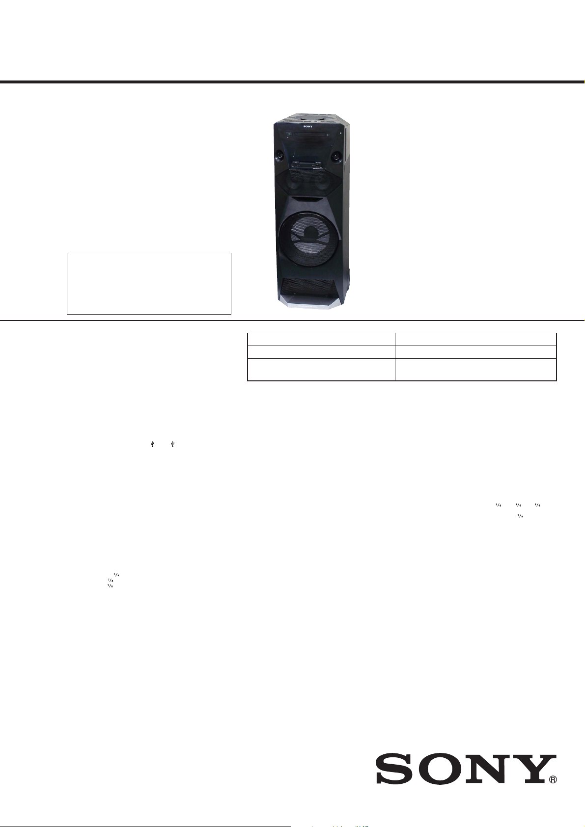
MHC-V5
SERVICE MANUAL
Ver. 1.3 2014.08
Note:
Be sure to keep your PC used for service and
checking of this unit always updated with the
latest version of your anti-virus software.
In case a virus affected unit was found during
service, contact your Service Headquarters.
Model Name Using Similar Mechanism NEW
CD Mechanism Type CDM90-DVBU202 or CDM90-DVBU204
Optical Pick-up Block Name
US Model
E Model
Australian Model
CMS-S76RFS7G or CMS-S76RFS7G1 or
CMS-S76RFS7GP
AUDIO POWER
SPECIFICATIONS
POWER OUTPUT AND TOTAL
HARMONIC DISTORTION: (USA model
only)
Left/Right Channel:
With 5 ohm loads, both channels
driven, from 800 – 20,000 Hz;
rated 150 watts per channel
minimum RMS power, with no
more than 0.7% total harmonic
distortion from 250 milliwatts to
rated output.
Amplifier section
Power output (rated):
Left/Right Channel: 320 W +
320W (at 5 ohms, 1 kHz, 1% THD)
Power output (reference):
Left/Right Channel: 480 W +
480W (per channel at 5 ohms,
1kHz)
Subwoofer: 480 W (at 5 ohms,
100Hz)
Speaker section
Speaker system: Tweeter + Mid range
speaker + woofer
Tweeter L/R: 40 mm (1
Mid L/R: 100 mm (3
Woofer: 250 mm (9
in) cone type
in) cone type
in) cone type
Inputs
AUDIO IN/PARTY CHAIN IN L/R:
Voltage 2 V, impedance
47kilohms
A (USB), B (USB) port:
Type A, maximum current:
500mA
Outputs
AUDIO OUT/PARTY CHAIN OUT L/R:
Voltage 2 V, impedance 47
kilohms
iPod/iPhone section
Made for
– iPhone 5s
– iPhone 5c
– iPhone 5
– iPhone 4s
– iPhone 4
– iPhone 3GS
–i Pod touch (5th generation)
–i Pod touch (4th generation)
Disc player section
System:
Compact disc and digital audio
system
Laser Diode Properties
Emission Duration: Continuous
Laser Output*: Less than 44.6 μW
* This output is the value
measurement at a distance of
200 mm from the objective lens
surface on the Optical Pick-up
Block with 7 mm aperture.
Frequency response:
20Hz – 20kHz
Signal-to-noise ratio:
More than 90dB
Dynamic range:
More than 88dB
SPECIFICATIONS
Tuner section
FM stereo, FM/AM superheterodyne
tuner
Antenna:
FM lead antenna
AM loop antenna
FM tuner section
Tuning range:
USA model:
87.5MHz - 108.0MHz (100kHz
step)
Other models:
87.5MHz - 108.0MHz (50kHz
step)
AM tuner section
Tuning range:
531kHz – 1,710kHz (9kHz step)
530kHz – 1,710kHz (10kHz step)
BLUETOOTH section
Communication system:
BLUETOOTH Standard version 3.0
Output:
BLUETOOTH Standard Power
Class 2
Maximum communication range:
Line of sight approx. 10 m
Frequency band:
2.4 GHz band (2.4000 GHz –
2.4835GHz)
Modulation method:
FHSS (Freq Hopping Spread
Spectrum)
Compatible BLUETOOTH profiles
A2DP (Advanced Audio
Distribution Profile)
AVRCP 1.3 (Audio Video Remote
Control Profile)
SPP (Serial Port Profile)
Supported codecs:
SBC (Sub Band Codec)
AAC (Advanced Audio Coding)
1)
The actual range will vary depending
on factors such as obstacles between
devices, magnetic fields around a
microwave oven, static electricity,
reception sensitivity, antenna’s
performance, operating system,
software application, etc.
2)
BLUETOOTH standard profiles
indicate the purpose of BLUETOOTH
communication between devices.
Supported audio formats
Supported bit rate:
MPEG1 Layer-3:
32 kbps – 320 kbps, VBR
WMA (USB devices only):
48 kbps – 192 kbps, VBR
2)
:
AAC (USB devices only):
48 kbps – 320 kbps, VBR
Sampling frequencies:
MPEG1 Layer-3:
32 kHz/44.1 kHz/48 kHz
WMA (USB devices only):
44.1 kHz
AAC (USB devices only):
44.1 kHz
1)
General
Power requirements:
USA model:
AC 120 V, 60 Hz
Argentina and Australian models:
AC 220 V – 240 V, 50/60 Hz
Mexican model:
AC 120 V – 240 V, 60 Hz
Other models:
AC 120 V – 240 V, 50/60 Hz
Power consumption:
240W (0.5 W at the Power Saving
mode)
Dimensions (w/h/d) (Approx.):
339 mm × 908 mm × 325 mm
in × 35 in × 12 in)
(13
Mass (Approx.):
18 kg (39lb 10
Supplied accessories:
Remote control (1)
R6 (Size AA) batteries (2)
AC power cord (1)
FM lead/AM loop antenna (1)
Design and specifications are subject
to change without notice.
oz)
9-893-954-04
2014H33-1
2014.08
©
HOME AUDIO SYSTEM
Sony Corporation
Published by Sony Techno Create Corporation
MHC-V5
License and Trademark Notice
WALKMAN® and W ALKMAN® logo
are registered trademarks of Sony
Corporation.
MPEG Layer-3 audio c oding
technology and patents licensed
from Fraunhofer IIS and Thomson.
Windows Media is either a
registered trademark or trademark
of Microsoft Corporation in
the United States and/or other
countries.
This product is protected by
certain intellectual property rights
of Microsoft Corporation. Use or
distribution of such technology
outside of this product is prohibited
without a license from Microsoft or
an authorized Microsoft subsidiar y.
The BLUETOOTH® word mark and
logos are registered trademarks
owned by Bluetooth SIG, Inc. and
any use of such marks by Sony
Corporation is under license. Other
trademarks and trade names ar e
those of their respective owners.
The N Mark is a trademark or
registered trademark of NFC Forum,
Inc. in the United States and in other
countries.
Android™ is a trademark of Google
Inc.
Google Play™ is a trademark of
Google Inc.
iPhone and iPod touch ar e
trademarks of Apple Inc., registered
in the U.S. and other countries. App
Store is a service mark of Apple Inc.
“Made f or iPod” and “Made for
iPhone” mean that an electr onic
accessory has been designed
to connect specically to iPod
or iPhone, respectively, and has
been certied by the developer
to meet Apple per formance
standards. Apple is not responsible
for the operation of this device
or its compliance with safety and
regulatory standards. Please note
that the use of this a ccessory with
iPod or iPhone may a ect wireless
performance.
All other trademarks and registered
trademarks are of their respective
holders. In this manual, ™ and ®
marks are not specied.
SAFETY CHECK-OUT
After correcting the original service problem, perform the following safety check before releasing the set to the customer:
Check the antenna terminals, metal trim, “metallized” knobs,
screws, and all other exposed metal parts for AC leakage.
Check leakage as described below.
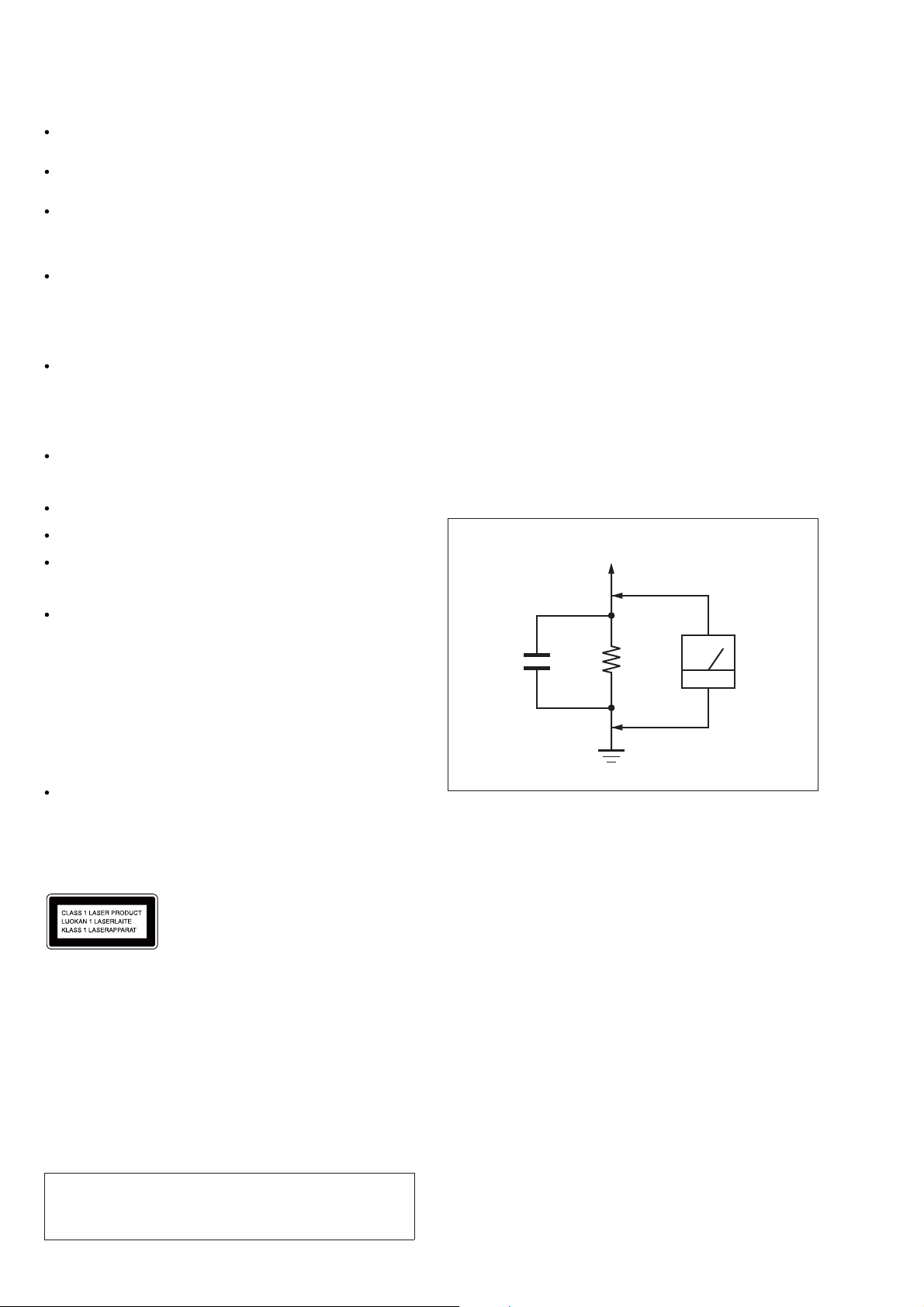
LEAKAGE TEST
The AC leakage from any exposed metal part to earth ground and
from all exposed metal parts to any exposed metal part having a
return to chassis, must not exceed 0.5 mA (500 microamperes.).
Leakage current can be measured by any one of three methods.
1. A commercial leakage tester, such as the Simpson 229 or RCA
WT-540A. Follow the manufacturers’ instructions to use these
instruments.
2. A battery-operated AC milliammeter. The Data Precision 245
digital multimeter is suitable for this job.
3. Measuring the voltage drop across a resistor by means of a
VOM or battery-operated AC voltmeter. The “limit” indication
is 0.75 V, so analog meters must have an accurate low-voltage
scale. The Simpson 250 and Sanwa SH-63Trd are examples
of a passive VOM that is suitable. Nearly all battery operated
digital multimeters that have a 2 V AC range are suitable. (See
Fig. A)
To Exposed Metal
Parts on Set
AC
1.5 kΩ0.15 μF
voltmeter
(0.75 V)
Earth Ground
Fig. A. Using an AC voltmeter to check AC leakage.
Except for customers in the
USA
This appliance is classied as a CLASS 1
LASER product. This marking is located
on the rear exterior.
NOTES ON CHIP COMPONENT REPLACEMENT
• Never reuse a disconnected chip component.
• Notice that the minus side of a tantalum capacitor may be damaged by heat.
CAUTION
Use of controls or adjustments or performance of procedures
other than those specifi ed herein may result in hazardous radia-
tion exposure.
2
SAFETY-RELATED COMPONENT WARNING!
COMPONENTS IDENTIFIED BY MARK 0 OR DOTTED LINE
WITH MARK 0 ON THE SCHEMATIC DIAGRAMS AND IN
THE PARTS LIST ARE CRITICAL TO SAFE OPERATION.
REPLACE THESE COMPONENTS WITH SONY PARTS
WHOSE PART NUMBERS APPEAR AS SHOWN IN THIS
MANUAL OR IN SUPPLEMENTS PUBLISHED BY SONY.

TABLE OF CONTENTS
MHC-V5
Ver. 1.3
1. SERVICING NOTES ............................................. 4
2. DISASSEMBLY
2-1. Disassembly Flow ........................................................... 7
2-2. Side L, R Panel Block ..................................................... 8
2-3. Top Panel Block .............................................................. 9
2-4. Loading Panel Block ....................................................... 10
2-5. CDM Block-1 ................................................................. 11
2-6. CDM Block-2 ................................................................. 12
2-7. Duct ................................................................................. 13
2-8. Back Panel Block ............................................................ 14
2-9. ARAGON Board-1 ......................................................... 15
2-10. ARAGON Board-2 ......................................................... 16
2-11. ARAGON Board-3 ......................................................... 16
2-12. D-AMP Board-1 .............................................................. 17
2-13. D-AMP Board-2 .............................................................. 18
2-14. Sub Chassis ..................................................................... 19
2-15. Front Panel-1 ................................................................... 19
2-16. Front Panel-2 ................................................................... 20
2-17. Switching Regulator (SWR1) ......................................... 21
2-18. Front Panel (SP) Block ................................................... 22
2-19. SPEAKER LED Board, Front Panel (SP) Assy .............. 23
2-20. Loudspeaker (25 cm) (Woofer) (SP5) ............................. 24
2-21. Loudspeaker (10 cm) (Mid: L-ch) (SP1) ........................ 25
2-22. Loudspeaker (10 cm) (Mid: R-ch) (SP3) ........................ 26
2-23. FL Board Block ............................................................... 27
2-24. Bluetooth Module (BT1) ................................................ 28
2-25. USB Board Block ........................................................... 29
2-26. NFC Module (NFC1) ...................................................... 30
2-27. FFC Holder ..................................................................... 31
2-28. Optical Pick-up (CMS-S76RFS7G) (OP1) ..................... 32
2-29. Volume Knob Block ........................................................ 33
3. TEST MODE ............................................................ 34
4. ELECTRICAL CHECKS ...................................... 37
5. DIAGRAMS
5-1. Block Diagram - CD/USB Section - ............................... 38
5-2. Block Diagram - MAIN Section - ................................... 39
5-3. Block Diagram - AMP Section - ..................................... 40
5-4. Block Diagram
- PANEL/POWER SUPPLY Section - ............................ 41
5-5. Schematic Diagram - MAIN Section (1/9) - ................... 43
5-6. Schematic Diagram - MAIN Section (2/9) - ................... 44
5-7. Schematic Diagram - MAIN Section (3/9) - ................... 45
5-8. Schematic Diagram - MAIN Section (4/9) - ................... 46
5-9. Schematic Diagram - MAIN Section (5/9) - ................... 47
5-10. Schematic Diagram - MAIN Section (6/9) - ................... 48
5-11. Schematic Diagram - MAIN Section (7/9) - ................... 49
5-12. Schematic Diagram - MAIN Section (8/9) - ................... 50
5-13. Schematic Diagram - MAIN Section (9/9) - ................... 51
5-14. Printed Wiring Boards - MAIN Section (1/2) - .............. 52
5-15. Printed Wiring Boards - MAIN Section (2/2) - .............. 53
5-16. Printed Wiring Board
- D-AMP Board (Component Side) - .............................. 54
5-17. Printed Wiring Board
- D-AMP Board (Conductor Side) - ................................ 55
5-18. Schematic Diagram - D-AMP Board (1/2) - ................... 56
5-19. Schematic Diagram - D-AMP Board (2/2) - ................... 57
5-20. Printed Wiring Board - USB Board (Former type) - ...... 58
5-21. Schematic Diagram - USB Board (Former type) - ......... 58
5-22. Printed Wiring Board - USB Board (New type) - ........... 59
5-23. Schematic Diagram - USB Board (New type) - ............. 59
5-24. Printed Wiring Boards - PANEL Section - ..................... 60
5-25. Schematic Diagram - PANEL Section - .......................... 61
5-26. Printed Wiring Boards - KEY Section - .......................... 62
5-27. Schematic Diagram - KEY Section - .............................. 63
6. EXPLODED VIEWS
6-1. Side Panel Section .......................................................... 75
6-2. Loading Panel Section .................................................... 76
6-3. Back Panel Section ......................................................... 77
6-4. D-AMP Board, ARAGON Board Section ...................... 78
6-5. Switching Regulator Section .......................................... 79
6-6. Speaker Cabinet Section ................................................. 80
6-7. Top Panel Section ........................................................... 81
6-8. Front Panel Section ......................................................... 82
6-9. CDM Block Section ........................................................ 83
6-10. CD Mechanism Deck Section
(CDM90-DVBU202 or CDM90-DVBU204) ................. 84
7. ELECTRICAL PARTS LIST .............................. 85
Accessories are given in the last of the electrical parts list.
Note 1: Refer to the “NEW/FORMER DISCRIMINATION OF USB
BOARD” on page 4 for how to distinguish New type and Former type of USB board. (Except Australian model)
Note 2: Refer to the service manual supplement-2 for information of
FL, TOP KEY A, TOP KEY B and USB boards of Australian
model.
3
MHC-V5
Ver. 1.3
SECTION 1
SERVICING NOTES
NOTES ON HANDLING THE OPTICAL PICK-UP
BLOCK OR BASE UNIT
The laser diode in the optical pick-up block may suffer electrostatic break-down because of the potential difference generated by
the charged electrostatic load, etc. on clothing and the human body.
During repair, pay attention to electrostatic break-down and also
use the procedure in the printed matter which is included in the
repair parts.
The fl exible board is easily damaged and should be handled with
care.
NOTES ON LASER DIODE EMISSION CHECK
The laser beam on this model is concentrated so as to be focused
on the disc refl ective surface by the objective lens in the optical
pickup block. Therefore, when checking the laser diode emission,
observe from more than 30 cm away from the objective lens.
UNLEADED SOLDER
Boards requiring use of unleaded solder are printed with the leadfree mark (LF) indicating the solder contains no lead.
(Caution: Some printed circuit boards may not come printed with
the lead free mark due to their particular size)
: LEAD FREE MARK
Unleaded solder has the following characteristics.
• Unleaded solder melts at a temperature about 40 °C higher
than ordinary solder.
Ordinary soldering irons can be used but the iron tip has to be
applied to the solder joint for a slightly longer time.
Soldering irons using a temperature regulator should be set to
about 350 °C.
Caution: The printed pattern (copper foil) may peel away if
the heated tip is applied for too long, so be careful!
• Strong viscosity
Unleaded solder is more viscous (sticky, less prone to fl ow)
than ordinary solder so use caution not to let solder bridges
occur such as on IC pins, etc.
• Usable with ordinary solder
It is best to use only unleaded solder but unleaded solder may
also be added to ordinary solder.
NOTE OF REPLACING THE MS-476 BOARD
When the MS-476 board is defective, replace the CDM90 ASSY
(Ref. No. CDM1).
NOTE OF REPLACING THE IC001, IC002, IC105, IC106,
IC302 AND IC306 ON THE ARAGON BOARD
IC001, IC002, IC105, IC106, IC302 and IC306 on the ARAGON
board cannot replace with single. When these parts are damaged,
replace the complete mounted board.
NOTE OF PERFORMING THE OPERATION CHECK IN
THE STATE THAT HEAT SINK WAS REMOVED
When performing the operation check in the state that this unit was
disassembled, it is possible to perform the operation check in the
state that heat sink was removed. But don’t perform the operation
check in the long time, and perform the operation check in the
volume state as low as possible.
RELEASING THE DISC TRAY LOCK
The disc tray lock function for the antitheft of sample disc in the
shop is equipped.
Disc tray lock function can be released by the following procedure.
Releasing Procedure:
1. Press the [
] button to turn the power on.
?/1
2. Press the [FUNCTION] button to turn the CD function.
3. Press two buttons of the [x] and [ENTER] simultaneously for
fi ve seconds.
4. The message “UNLOCKED” is displayed on the fl uorescent
indicator tube and the disc tray is unlocked.
Note: When “LOCKED” is displayed, the disc tray lock is not released by
turning power on/off with the [
?/1
] button.
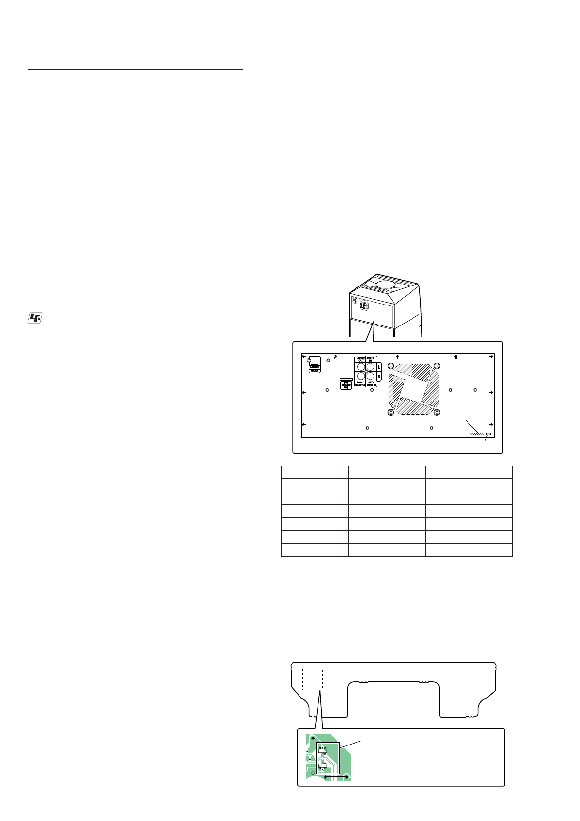
MODEL IDENTIFICATION
Distinguish by Part No. and Destination code on the rear side of
a main unit.
– Rear View –
– Back Panel –
Part No.
Destination code
Part No. Destination code Destination
4-484-682-0[]
4-484-682-1[]
4-484-682-2[]
4-484-682-4[]
4-484-682-5[]
4-484-682-7[]
E2 120V AC Area in E
AU1 Australian
U2 US
E51 Chilean and Peruvian
MX4 Mexican
AR2 Argentina
NEW/FORMER DISCRIMINATION OF USB BOARD
(120V AC area in E, Chilean, Peruvian, Mexican and Argentina
models only)
As for this unit, circuit on the USB board has been changed in the
midway of production.
Distinguish of New/Former type of USB board, please refer to the
following fi gure.
– USB Board (Conductor Side) –
TEST DISCS
Use following TEST DISC (for CD) when this unit confi rms the
operation and checks it.
Part No. Description
3-702-101-01 DISC (YEDS-18), TEST
4-225-203-01 DISC (PATD-012), TEST
J-2501-307-A DISC (HLX-A1), TEST
4
AK
D2208
JW2700
A/K
K/A
D2210
KA
JW2702
200
(120V AC area in E, Chilean, Peruvian,
Mexican and Argentina models only)
D2208/D2210
Former type : Mount
New type : No mount
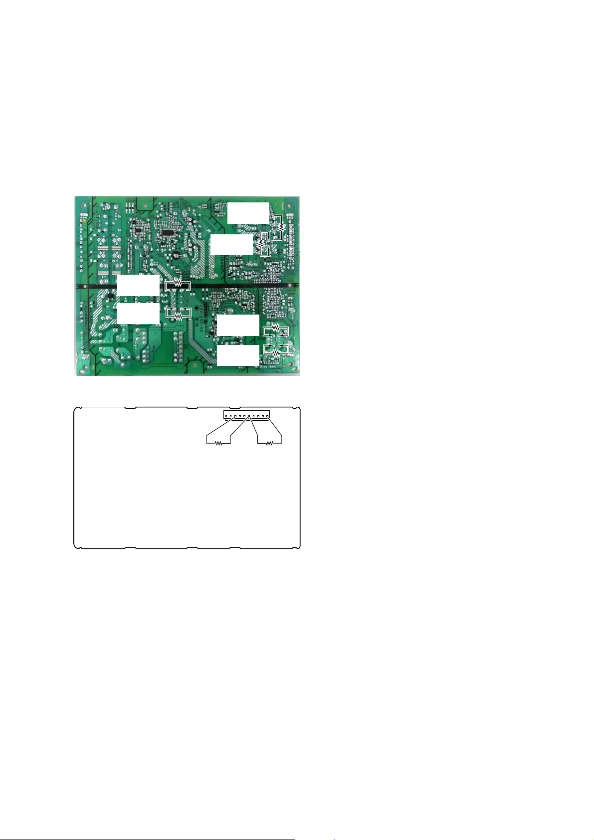
CAPACITOR ELECTRICAL DISCHARGE PROCESSING
When checking the board, the electrical discharge is necessary for
the electric shock prevention.
Connect the resistor to both ends of respective capacitors.
• D-AMP board
CN1000 (pin 6 and 10, pin 6 and 3)
• Switching regulator (SWR1)
C202, C203, C403, C407, C531 and C532
– Switching Regulator (Conductor Side) –
800 :/2 W
(for C403)
800 :/2 W
(for C407)
800 :/2 W
(for C531)
800 :/2 W
(for C532)
800 :/2 W
(for C203)
MHC-V5
– D-AMP Board (Conductor Side) –
800 :/2 W
(pin 3 and 6)
800 :/2 W
(for C202)
CN1000
110
800 :/2 W
(pin 6 and 10)
5

MHC-V5
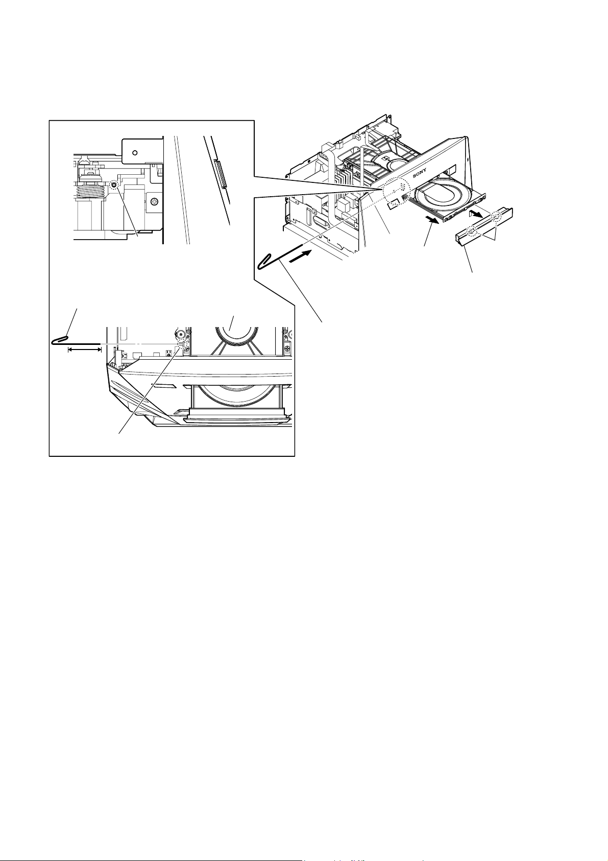
HOW TO OPEN THE TRAY WHEN POWER SWITCH TURN OFF
Note 1: After the side panel and top panel are removed, this work is done.
Note 2: Please prepare the thin wire (clip etc. processed to the length of 8 cm or more).
thin wire (clip etc. )
8 cm or more
hole
hole
– Left view –
2 Draw out the tray.
CD mechanism deck
1 Insert the clip etc. in the hole,
and push the lever in the direction
of the arrow.
tray
– Top view –
6

DISASSEMBLY
• This set can be disassembled in the order shown below.
2-1. DISASSEMBLY FLOW
SET
2-2. SIDE L, R PANEL BLOCK
(Page 8)
2-3. TOP PANEL BLOCK
(Page 9)
2-29. VOLUME KNOB BLOCK
(Page 33)
2-4. LOADING PANEL BLOCK
(Page 10)
Note:
of production.
SECTION 2
Duct is deleted from the midway
MHC-V5
Ver. 1.1
JIG
When disassembling the unit, use the following
jig for speaker removal.
Part No. Description
J-2501-238-A JIG FOR SPEAKER REMOVAL
2-5. CDM BLOCK-1
(Page 11)
2-6. CDM BLOCK-2
(Page 12)
2-27. FFC HOLDER
(Page 31)
2-28. OPTICAL PICK-UP BLOCK
(CMS-S76RFS7G) (OP1)
(Page 32)
2-18. FRONT PANEL (SP) BLOCK
(Page 22)
2-19. SPEAKER LED BOARD,
FRONT PANEL (SP) ASSY
(Page 23)
2-7. DUCT
(Page 13)
2-8. BACK PANEL BLOCK
(Page 14)
2-9. ARAGON BOARD-1
(Page 15)
2-10. ARAGON BOARD-2
(Page 16)
2-11. ARAGON BOARD-3
(Page 16)
2-23. FL BOARD BLOCK
(Page 27)
2-24. BLUETOOTH MODULE (BT1)
(Page 28)
2-12. D-AMP BOARD-1
(Page 17)
2-13. D-AMP BOARD-2
(Page 18)
2-14. SUB CHASSIS
(Page 19)
2-15. FRONT PANEL-1
(Page 19)
2-16. FRONT PANEL-2
(Page 20)
2-17. SWITCHING REGULATOR
(SWR1)
(Page 21)
2-20. LOUDSPEAKER (25 cm)
(WOOFER) (SP5)
(Page 24)
2-21. LOUDSPEAKER (10 cm)
(MID: L-CH) (SP1)
(Page 25)
2-22. LOUDSPEAKER (10 cm)
(MID: R-CH) (SP3)
(Page 26)
2-25. USB BOARD BLOCK
(Page 29)
2-26. NFC MODULE (NFC1)
(Page 30)
7

MHC-V5
Ver. 1.1
Note: Follow the disassembly procedure in the numerical order given.
2-2. SIDE L, R PANEL BLOCK
Note 1: Side L panel and side R panel has been changed from the mid-
way of production. Four screw caps are deleted at the same
time. Please distinguish the new type and the former type with
the numbers of screw caps.
(Former type)
3 screw cap
2 claw
3 screw cap
2 claw
2 claw
3 screw
cap
2 two
claws
(Former type)
2 claw
(Former type)
2 claw
Insert needle-nose pliers behind
1
the second fin, and press
in the direction of the arrow.
Note 2:
needle-nose pliers
4 three screws
(BVTP3 u 10)
Do not damage screw cap.
6 side L panel block
5 Remove the side L panel block
in the direction of the arrow.
4 three screws
(BVTP3 u 10)
2 claw
2 claw
3 screw cap
(Former type)
2 claw
3 screw cap
2 claw
2 claw
Insert needle-nose pliers behind
1
the second fin, and press
in the direction of the arrow.
Note 2:
3 screw cap
Do not damage screw cap.
needle-nose pliers
4 three screws
(BVTP3 u 10)
6 side R panel block
5 Remove the side R panel block
in the direction of the arrow.
4 three screws
(BVTP3 u 10)
8

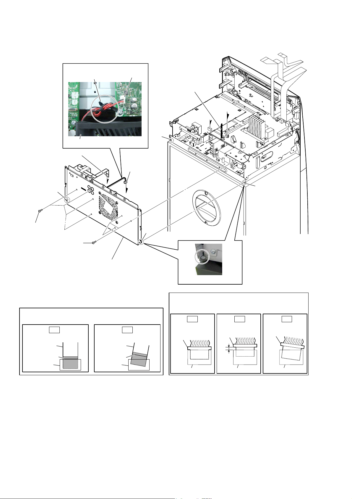
2-3. TOP PANEL BLOCK
MHC-V5
Ver. 1.1
3 Remove the top panel block
in the direction of the arrow.
7 top panel block
1 three screws
(BVTP3 u 10)
WireVeWWiQJ
TOP KEY A board
Terminal face is
below side.
6 flexible flat
cable (15P)
(CN2100)
When installing the flexible flat cable,
Note 2:
the colored line is not slanted after insertion.
OK NG
Insert is straight to the interior. Insert is incline
flexible flat
cable
colored line
connectorconnector
flexible flat cable (4P)
guide line
guide line
2 five claws
5 flexible flat
cable (4P)
(CN2102)
flexible flat
cable
colored line
WireVeWWiQJ
4 cushion (H)
ensure that
guide line
Terminal face is
below side.
–7RSSDQeOEORFN
ERWWRPYieZ–
–7RSreDrYieZ–
flexible flat cable
(15P)
Fix the cushion (H) so that
Note 1:
the flexible flat cable does not
come in contact with the heat sink.
guide line
cushion (H)
heat sink
9
MHC-V5
2-4. LOADING PANEL BLOCK
thin wire (clip etc. )
8 cm or more
hole
– Left view –
hole
CD mechanism deck
tray
– Top view –
2 Draw out the tray.
4 loading panel block
1 Insert the clip etc. in the hole,
and push the lever in the direction
of the arrow.
3 two
claws
10
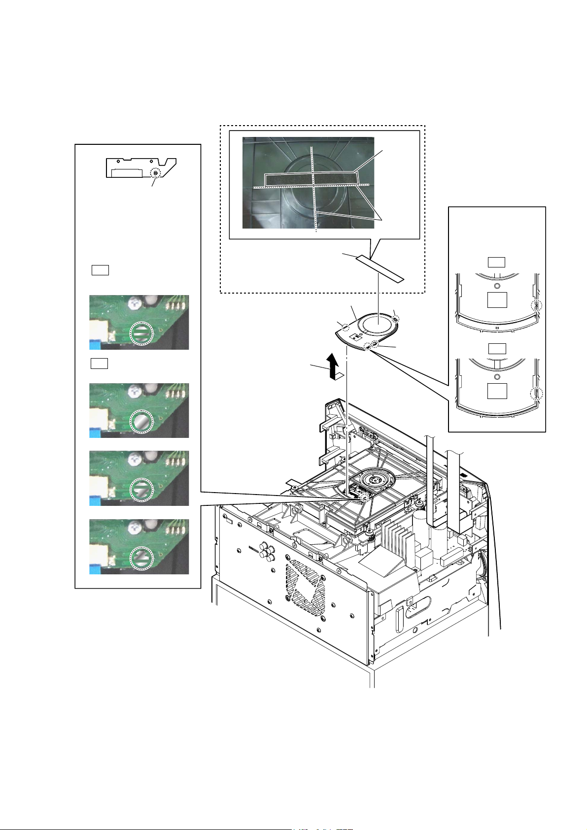
2-5. CDM BLOCK-1
• Continued on 2-6 (page 12).
Note 1: Before disconnecting fl exible fl at cable (24P) (CN302), solder the short-land.
Solder the short-land.
5
Note 2: When assembling the CDM
block, remove the solder of
short-land after connecting
flexible flat cable (24P)
(CN302).
OK
Solder is removed cleanly.
Cushion (E) is deleted from
Note 4:
the midway of production.
1 cushion (E)
cushion (E)
guide line
MHC-V5
Ver. 1.1
When installing
Note 3:
the chuck cap,
align the triangle
marks.
OK
NG
Solder is not removed.
3 Remove the chuck cap
in the direction
of the arrow.
4 chuck cap
2 claw
2 claw
2 claw
NG
– Top rear view –
11
MHC-V5
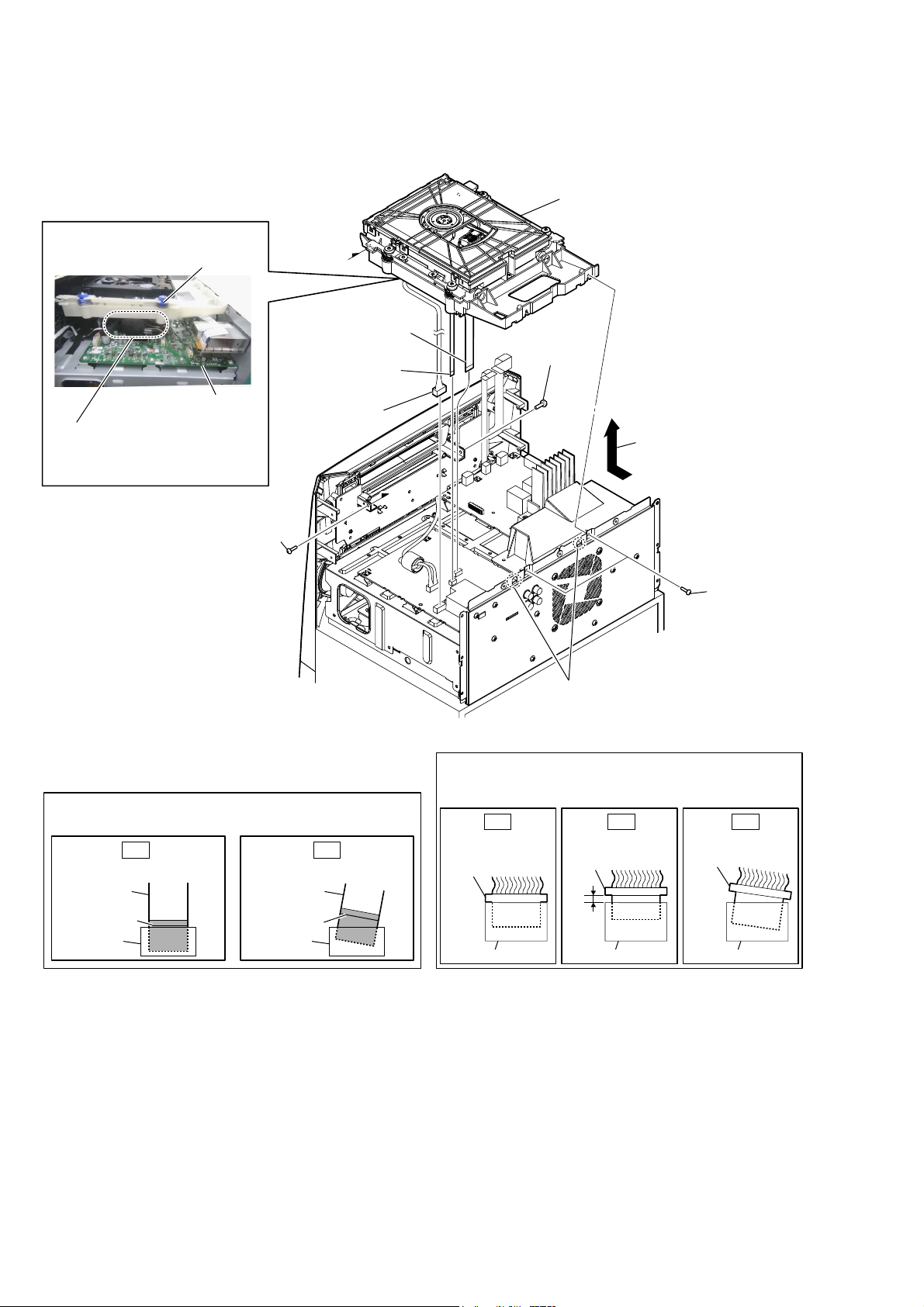
2-6. CDM BLOCK-2
WireVeWWiQJ
CDM block
7 CDM block
6 flexible flat cable
(24P) (CN302)
5 flexible flat cable
(5P) (CN303)
ARAGON board
Connect the wire from the CDM
Note 1:
block to the ARAGON board and
place it neatly inside the CDM
block.
1 screw
(BVTP3 u 10)
When installing the flexible flat cable,
Note 2:
the colored line is not slanted after insertion.
OK NG
Insert is straight to the interior. Insert is incline
flexible flat
cable
colored line
colored line
connectorconnector
4 connector
(CN401)
ensure that
flexible flat
cable
–7RSreDrYieZ–
Note 3:
There is a possibility that this machine damages when not
correctly installing it.
Insert is straight
to the interior.
connector
connector
1 screw
(BVTP3 u 10)
3 Remove the CDM block
in the direction of the arrow.
1 two screws
(BVTP3 u 10)
2 two hooks
When you install the connector, please install them correctly.
OK NG NG
Insert is shallow
connector
connector connector
Insert is incline
connector
12
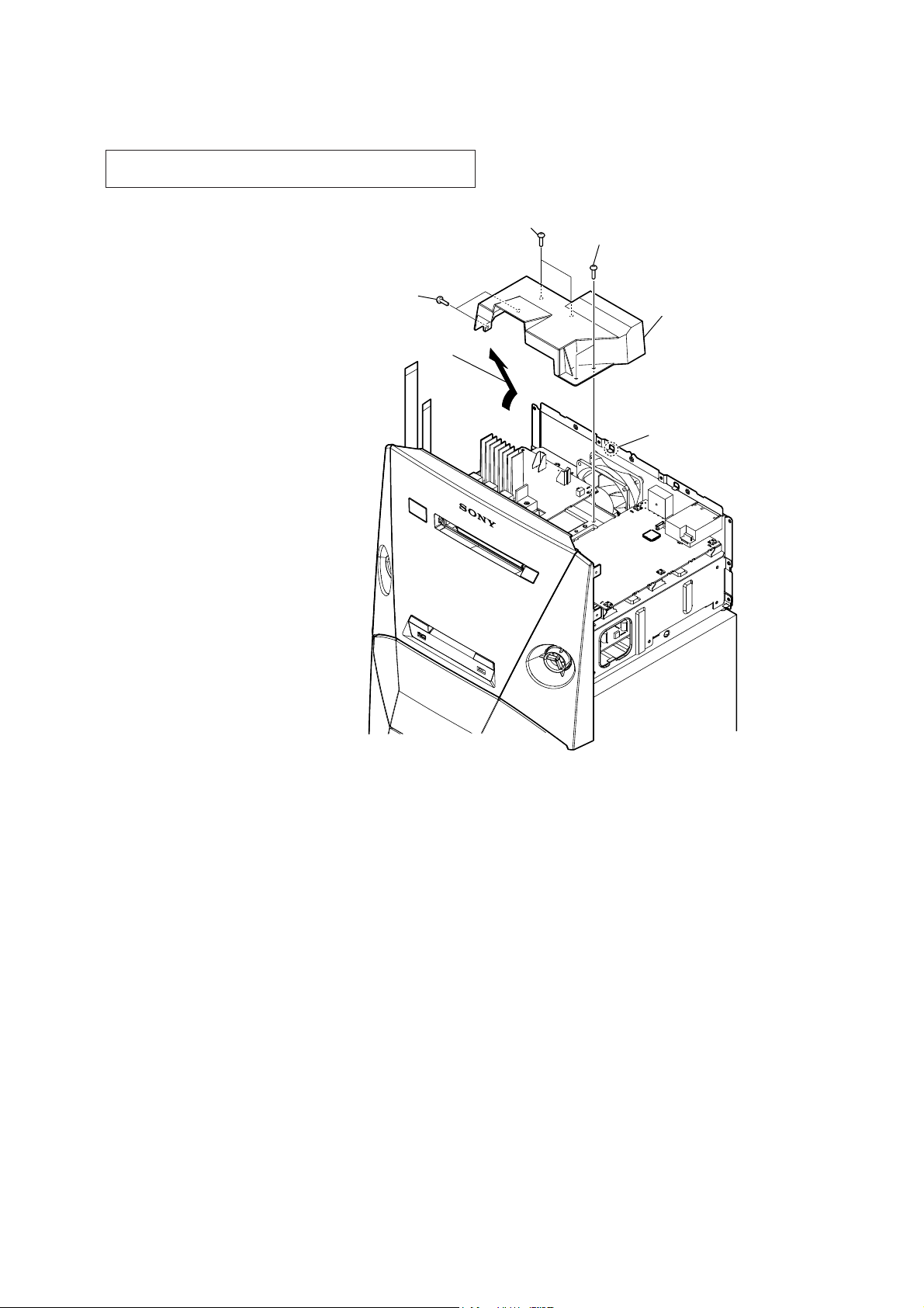
2-7. DUCT
Note: DUCT is deleted from the midway of production. Six screws
(BV/RING) are deleted at the same time.
1 two screws
(BV/RING)
3 Remove the duct in the direction
of the arrow.
MHC-V5
Ver. 1.1
1 two screws
(BV/RING)
1 two screws
(BV/RING)
4 duct
2 hook
13
MHC-V5
2-8. BACK PANEL BLOCK
'& faQ wire VettiQJ
coating clip
CN1003
1 Remove the DC fan wire
from the coating clip.
B
A
DC fan
3 flexible flat cable (9P)
(CN851)
hook
4 four screws
(BV/RING)
4 three screws
(BV/RING)
5 back panel block
Note 1:
align two hooks and two holes.
When installing the flexible flat cable,
Note 2:
the colored line is not slanted after insertion.
OK NG
Insert is straight to the interior. Insert is incline
flexible flat
cable
colored line
When installing the back panel block,
flexible flat
cable
colored line
connectorconnector
2 DC fan connector
(CN1003)
A
B
ensure that
hook
hole
hole
– Top rear view –
– Left view –
When you install the connector, please install them correctly.
Note 3:
There is a possibility that this machine damages when not
correctly installing it.
OK NG NG
Insert is straight
to the interior.
connector
connector
Insert is shallow
connector
connector connector
connector
Insert is incline
14

2-9. ARAGON BOARD-1
• Continued on 2-10 (page 16).
:LUHVHWWLQJ
coating clip
:LUHVHWWLQJ
ARAGON board
3 Remove the wire
from the coating clip.
7 flexible flat cable (10P)
(CN102)
4 connector
(CN001)
1 cushion (H)
:LUHVHWWLQJ
cushion (H)
2 flexible flat cable (19P)
(CN110)
MHC-V5
Ver. 1.3
D-AMP board
ARAGON board
wire
cushion (E 0.5)
Cushion (E 0.5) is deleted from
Note 3:
the midway of production.
([FHSW86$XVWUDOLDQ
When installing the flexible flat cable,
Note 1:
the colored line is not slanted after insertion.
OK NG
Insert is straight to the interior. Insert is incline
flexible flat
cable
colored line
ARAGON
board
ensure that
flexible flat
cable
colored line
connectorconnector
6 connector
(CN451)
([FHSW86
$XVWUDOLDQ
5 cushion (E 0.5)
Cushion (E 0.5) is deleted from
–7RSUHDUYLHZ–
When you install the connector, please install them correctly.
Note 2:
There is a possibility that this machine damages when not
correctly installing it.
OK NG NG
Insert is straight
to the interior.
connector
connector
Note 3:
the midway of production.
Insert is shallow
connector
connector connector
Insert is incline
connector
15

MHC-V5
Ver. 1.3
2-10. ARAGON BOARD-2
• Continued on 2-11.
:LUHVHWWLQJ
cushion (H)
1 cushion (H)
FL board
When installing the flexible flat cable,
Note:
the colored line is not slanted after insertion.
OK NG
Insert is straight to the interior. Insert is incline
flexible flat
cable
colored line
ARAGON board
ensure that
flexible flat
cable
colored line
connectorconnector
2-11. ARAGON BOARD-3
1 screw
(BV/RING)
1 four screws
(BV/RING)
2 coating clip
2 flexible flat cable (8P)
(CN105)
(US, Australian)
3 filament tape
(sub material)
4 sheet
(EMC-absober)
–7RSUHDUYLHZ–
5 ARAGON board
3 flexible flat cable (23P)
(CN109)
16
– Top rear view –
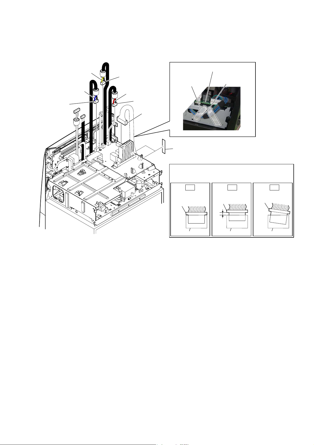
2-12. D-AMP BOARD-1
• Continued on 2-13 (page 18).
MHC-V5
3 connector
(CN1009)
[yellow]
[blue]
4 connector
(CN1008)
[red]
5 connector
(CN1010)
2 connector
(CN1000)
:ire VeWWiQJ
filament tape
(sub material)
1 two filament tapes
(sub material)
When you install the connector, please install them correctly.
Note:
There is a possibility that this machine damages when not
correctly installing it.
OK NG NG
Insert is straight
to the interior.
connector
D-AMP board
– /eIW view –
Insert is shallow
connector
filament tape
(sub material)
Insert is incline
connector
– Top rear view –
connector
connector connector
17

MHC-V5
Ver. 1.1
2-13. D-AMP BOARD-2
)OH[LEOHIODWFDEOH3VHWWLQJ
short
Terminal face is
CN1006
below side.
long
D-AMP
board
Terminal face
to D-AMP board
1 flexible flat cable (19P)
(CN1006)
2 two screws
(BV/RING)
2 two screws
(BV/RING)
2 screw
(BV/RING)
3 coating
clip
4 two screws
(PTPWH2.6 u L)
6 heat sink
7 thermal sheet
2 screw
(BV/RING)
8 D-AMP board
5 bracket
(HS)
–7RSUHDUYLHZ–
When installing the flexible flat cable,
Note:
the colored line is not slanted after insertion.
OK NG
Insert is straight to the interior. Insert is incline
flexible flat
cable
colored line
ensure that
flexible flat
cable
colored line
connectorconnector
18

MHC-V5
2-14. SUB CHASSIS
2 two screws
(BV/RING)
4 sub chassis
2 screw
(BV/RING)
1 screw
(PSW M3 u 10)
hole
2 screw
(BV/RING)
3 Draw out the wire from hole.
2-15. FRONT PANEL-1
• Continued on 2-16 (page 20).
:LUHVHWWLQJ
FL board
coating clip
– Top rear view –
1 Remove the wire from
the coating clip.
3 Remove the wire from
the coating clip.
:LUHVHWWLQJ
FL board
coating clip
:LUHVHWWLQJ
FL board
coating clip
2 Remove the wire from
the coating clip.
–7RSUHDUYLHZ–
4 Remove the wire from
the coating clip.
:LUHVHWWLQJ
USB board
coating clip
19

MHC-V5
Ver. 1.1
2-16. FRONT PANEL-2
wire
wire
4 two screws
(BV/RING)
When you install the connector, please install them correctly.
Note 2:
There is a possibility that this machine damages when not
correctly installing it.
OK NG NG
Insert is straight
to the interior.
connector
Insert is shallow
connector
Insert is incline
connector
([FepW 86
Ground (USB L) plate
Note 3:
and ground (USB R)
plate has been changed
into wire from the
midway of production.
6 front panel block
5 two bosses
ground (USB L) plate
ground (USB R) plate
4 two screws
(BV/RING)
5 boss
C
2 terminal
(narrow side)
[yellow]
5 boss
connector
:ire VeWWiQJ
[yellow]
3 connector
(CN2002)
2 terminal
(wide side)
[black]
connector connector
Pass the wire (flat type) (4 core)
Note 1:
over the top of the loudspeaker.
[black]
C
1 terminal
(narrow side)
[blue]
:ire VeWWiQJ
1 terminal
(wide side)
[black]
[black]
– Top rear view –
[blue]
20

2-17. SWITCHING REGULATOR (SWR1)
1 Remove the wire from
the coating clip.
:ire VeWWiQJ
switching regulator
(SWR1)
MHC-V5
coating clip
5 three screws
(BV/RING)
7 switching regulator
(SWR1)
5 screw
(BV/RING)
6 coating clip
4 connector
(CN201)
5 two screws
(BV/RING)
2 connector
(CN101)
– Top rear view –
3 connector
(CN401)
5 two screws
(BV/RING)
When you install the connector, please install them correctly.
Note:
There is a possibility that this machine damages when not
correctly installing it.
Insert is straight
to the interior.
connector
OK NG NG
connector
Insert is shallow
connector
connector connector
Insert is incline
connector
21
MHC-V5
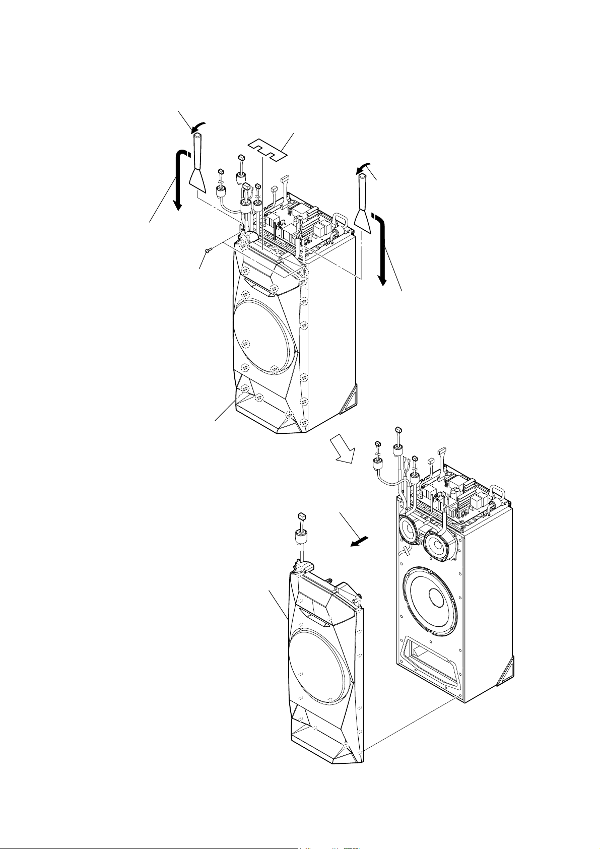
2-18. FRONT PANEL (SP) BLOCK
3 Insert the jig into the space and slowly
remove the front panel (SP) block.
Note:
so as not to injure front panel (SP)
block and speaker cabinet.
When using a jig, please work
4 All bosses are removed while moving
jig in the direction of the arrow, and
front panel (SP) block is removed.
2 two tapping screws
(3.5 u 14)
1 screw cushion
3 Insert the jig into the space and slowly
remove the front panel (SP) block.
Note:
so as not to injure front panel (SP)
block and speaker cabinet.
4 All bosses are removed while moving
jig in the direction of the arrow, and
front panel (SP) block is removed.
When using a jig, please work
total nineteen bosses
6 front panel (SP) block
5 Remove the front panel (SP) block
in the direction of the arrow.
22
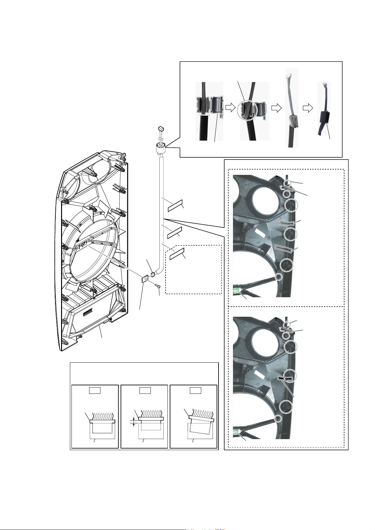
2-19. SPEAKER LED BOARD, FRONT PANEL (SP) ASSY
6OHHYHIHUULWHFODPS)&VHWWLQJ
MHC-V5
Ver. 1.1
Wrap twice.
–)URQWSDQHO63DVV\UHDUYLHZ–
3 connector
(CN1800)
1 cushion (H)
1 cushion (H)
1 cushion (H)
Cushion (H) is
Note 1:
deleted from the
midway of
production.
2 screw
(BVTP3 u 8)
4 SPEAKER LED board
sleeve ferrite clamp
(FC5)
:LUHVHWWLQJ
cushion
(E 0.5)
)RUPHUW\SH
total six grooves
cushion (H)
cushion (H)
cushion (H)
SPEAKER LED board
NHZW\SH
total six grooves
cushion (H)
5 front panel (SP) assy
When you install the connector, please install them correctly.
Note 2:
There is a possibility that this machine damages when not
correctly installing it.
OK NG NG
Insert is straight
to the interior.
connector
connector
Insert is shallow
connector
connector connector
connector
Insert is incline
cushion (H)
SPEAKER LED board
23
MHC-V5
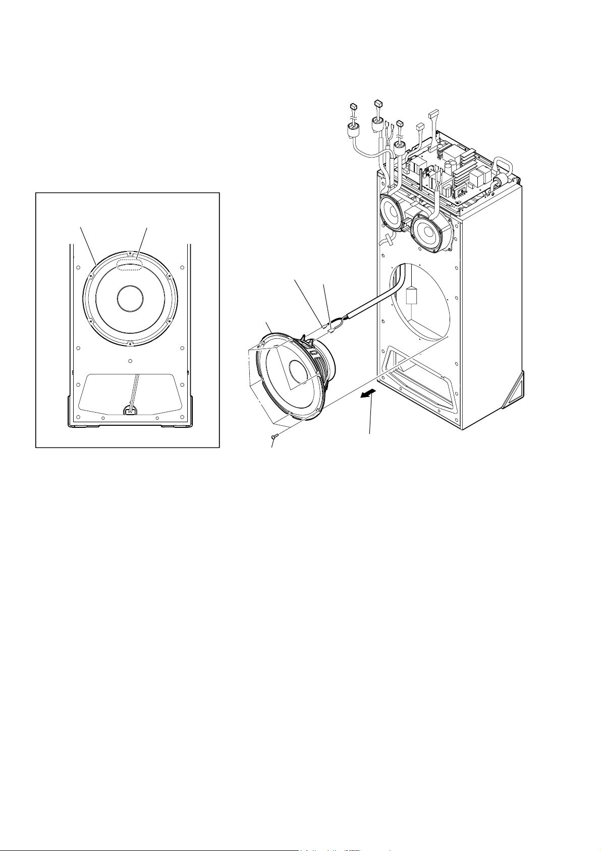
2-20. LOUDSPEAKER (25 cm) (WOOFER) (SP5)
+RZWRLQVWDOOWKHORXGVSHDNHUFP63
loudspeaker (25 cm)
(SP5)
terminal position
3 terminal
(narrow side)
[black]
4 loudspeaker
(25 cm) (woofer)
(SP5)
1 six screws
(BVTP4 u 20)
3 terminal
(wide side)
[red]
2 Remove the loudspeaker (25 cm) (SP5)
in the direction of the arrow.
24

2-21. LOUDSPEAKER (10 cm) (MID: L-CH) (SP1)
MHC-V5
+RZWRLQVWDOOWKHORXGVSHDNHUFP63
loudspeaker (10 cm)
(SP1)
:LUHVHWWLQJ
rib
terminal position
rib
:LUHVHWWLQJ
loudspeaker
(10 cm) (SP1)
terminal
(narrow side)
groove
terminal
(wide side)
4 terminal
(narrow side)
4 terminal
(wide side)
speaker cable
1 Remove the speaker cable.
5 loudspeaker (10 cm)
(mid: L-ch) (SP1)
2 four tapping screws
(3.5 u 14)
3 Remove the loudspeaker (10 cm) (SP1)
in the direction of the arrow.
–)URQWOHIWYLHZ–
25

MHC-V5
2-22. LOUDSPEAKER (10 cm) (MID: R-CH) (SP3)
+RZWRLQVWDOOWKHORXGVSHDNHUFP63
loudspeaker (10 cm)
(SP3)
:LUHVHWWLQJ
cushion (H)
:LUHVHWWLQJ
rib
terminal position
wire
rib
1 cushion (H)
:LUHVHWWLQJ
groove
terminal
(narrow side)
terminal
(wide side)
loudspeaker
(10 cm) (SP3)
5 terminal
(narrow side)
5 terminal
(wide side)
wire
2 Remove the wire.
6 loudspeaker (10 cm)
(mid: R-ch) (SP3)
3 four tapping screws
(3.5 u 14)
4 Remove the loudspeaker (10 cm) (SP3)
in the direction of the arrow.
–)URQWOHIWYLHZ–
26

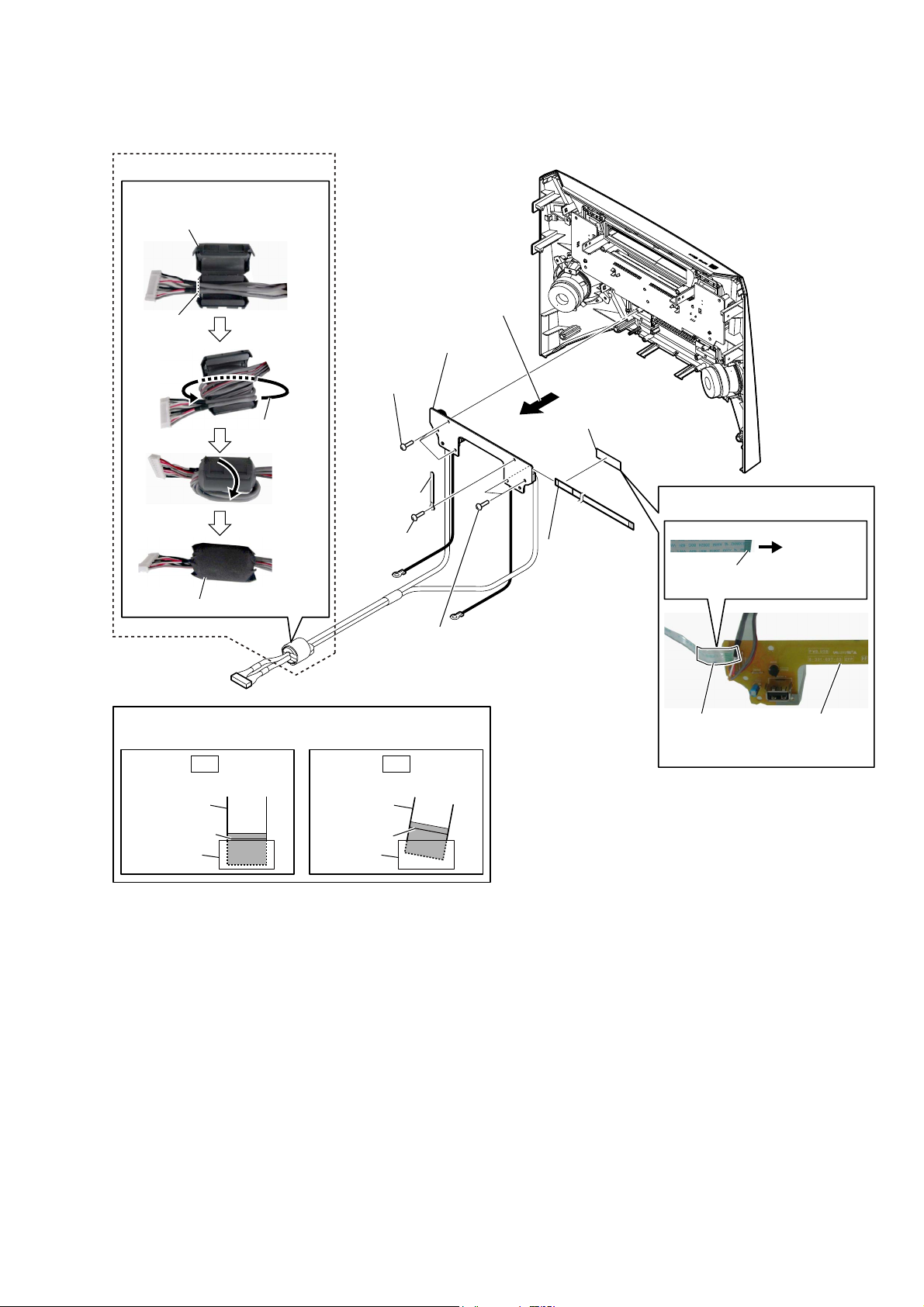
2-23. FL BOARD BLOCK
MHC-V5
Ver. 1.3
WireVHWWLQJ
ferrite core
(FC4)
filament tape
(sub material)
)HUULWHFRUH)&VHWWLQJ
flexible flat cable
(23P)
FL board
2 three screws
(BVTP3 u 8)
2 screw
(BVTP3 u 8)
3 coating clip
9 flexible flat cable
(23P) block
(CN2000)
2 screw
(BVTP3 u 8)
guide line
Terminal
face
filament tape
(sub material)
2 screw
(BVTP3 u 8)
3 coating
clip
2 screw
(BVTP3 u 8)
to FL board
8 filament tape
(sub material)
3 coating
clip
to FL board
0 FL board
block
7 flexible flat cable
(15P) block
(CN2001)
4 sheet
(FL)
Sheet (FL) is deleted
Note 3:
from the midway of
production.
WireVHWWLQJ
short
Terminal
face
long
–)URQWSDQHOUHDUYLHZ–
5 Remove the FL board block
in the direction of the arrow.
6 filament tape
(sub material)
)HUULWHFRUH)&VHWWLQJ
guide line
1 cushion
(H)
ferrite core
cushion (H)
(FC4)
flexible flat cable (15P)
ferrite core (FC4)
cushion (E 0.5)
cushion (E 0.5)
ferrite core
(FC1)
ferrite core
(FC1)
FL board
Cushion (H), cushion (E 0.5) and
Note 2:
ferrite core (FC4) are deleted from
the midway of production.
(Except US and Australian models)
When installing the flexible flat cable,
Note 1:
the colored line is not slanted after insertion.
OK NG
Insert is straight to the interior. Insert is incline
flexible flat
cable
colored line
ensure that
flexible flat
cable
colored line
connectorconnector
cushion
(E 0.5)
cushion
(E 0.5)
27

MHC-V5
Ver. 1.1
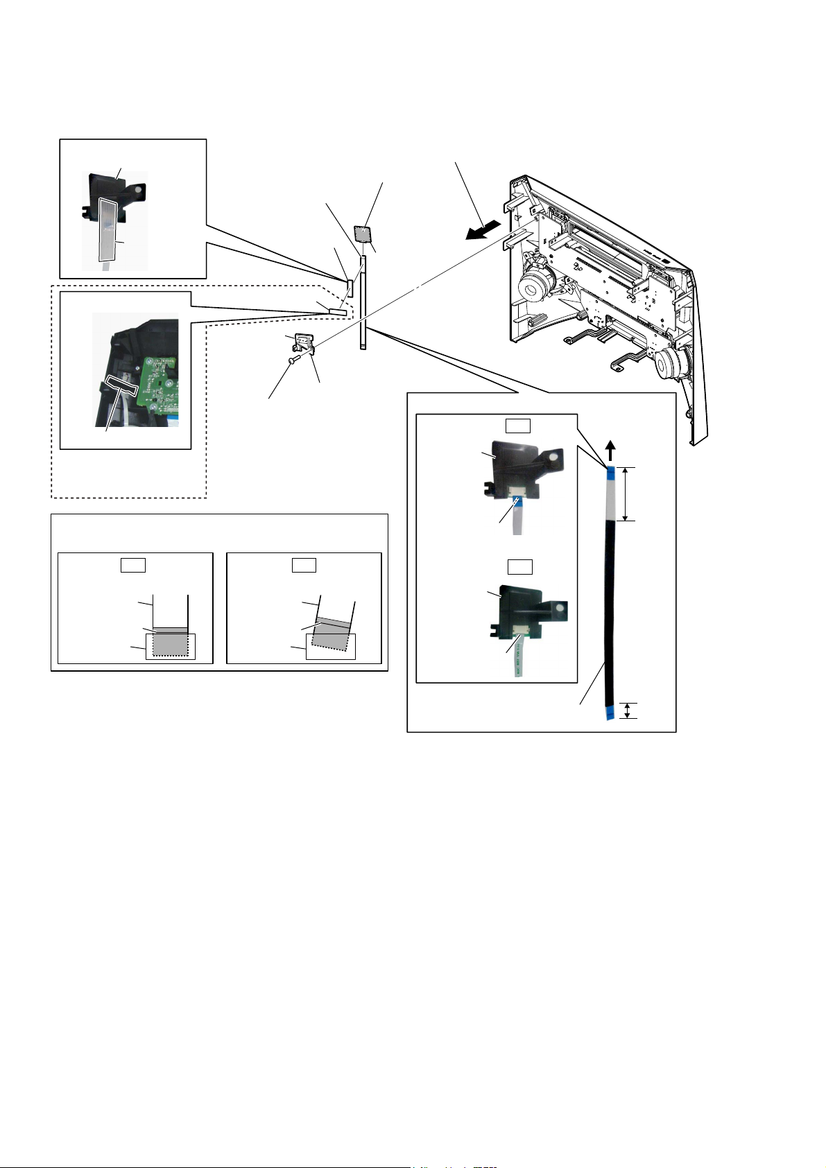
2-24. BLUETOOTH MODULE (BT1)
WireVeWWiQJ
short
WireVeWWiQJ
filament tape
(sub material)
bluetooth module
(BT1)
flexible flat cable (10P)
(FFC7)
3 filament tape
(sub material)
long
2 Remove the bluetooth
module (BT1) in the
direction of the arrow.
5 bluetooth module
(BT1)
4 flexible flat cable (10P)
(FFC7)
+RZWRiQVWDOOWKeEOXeWRRWKPRGXOe%7
to
bluetooth
module
(BT1)
–)rRQWSDQeOreDrYieZ–
1 cishion (H)
cushion (H)
OK NG
Terminal face is
below side
bluetooth module
(BT1)
When installing the flexible flat cable,
Note:
the colored line is not slanted after insertion.
OK NG
Insert is straight to the interior. Insert is incline
flexible flat
cable
colored line
Terminal face
bluetooth module
(BT1)
ensure that
flexible flat
cable
colored line
connectorconnector
bluetooth module
(BT1)
28
2-25. USB BOARD BLOCK
(US, Australian)
)errite FRre ()&) setting
ferrite core (FC3)
guide line
MHC-V5
Ver. 1.3
– )rRnt Sanel rear view –
3 Remove the USB board block
in the direction of the arrow.
6 USB board block
1 three screws
(BVTP3 u 8)
Wrap once.
2 coating clip
1 screw
(BVTP3 u 8)
cushion (E 0.5)
When installing the flexible flat cable,
Note:
the colored line is not slanted after insertion.
OK NG
Insert is straight to the interior. Insert is incline
flexible flat
cable
colored line
ensure that
flexible flat
cable
colored line
connectorconnector
1 two screws
(BVTP3 u 8)
4 filament tape
(sub material)
5 flexible flat
cable (4P)
(CN2202)
Wire setting
Terminal
face
filament tape
(sub material)
to USB board
USB board
29
MHC-V5
Ver. 1.1
2-26. NFC MODULE (NFC1)
WireVeWWiQJ
NFC module block
filament tape
(sub material)
WireVeWWiQJ
cushion (H)
Cushion (H) is deleted
Note 2:
from the midway of
production.
When installing the flexible flat cable,
Note 1:
the colored line is not slanted after insertion.
3 Peel off the adhesive sheet (NFC).
6 flexible flat cable (8P)
(FFC6)
5 filament tape
(sub material)
1 cushion (H)
7 Peel off the
tape (NFC).
2 screw
(BVTP3 u 8)
ensure that
9 NFC module
(NFC1)
8 NFC holder
4 Remove the NFC module block
in the direction of the arrow.
WireVeWWiQJ
OK
NFC module
block
Terminal face is
below side
–)rRQWSDQeOreDrYieZ–
to
NFC module
(NFC1)
long
OK NG
Insert is straight to the interior. Insert is incline
flexible flat
cable
colored line
flexible flat
cable
colored line
connectorconnector
NFC module
block
Terminal face
flexible flat cable (8P)
(FFC6)
NG
short
30
 Loading...