

Page 1
Models TB60/TB60RT
Replaces 0083739 March 2014
OPERATOR’S
MANUAL
Part Number 0083739
June 2014
Page 2

The aerial platform is not electrically insulated. Death or serious injury will result from contact
with, or inadequate clearance from, an energized conductor.
Do not go closer than the minimum safe approach distance as dened by the Minimum Safe
Approach Distance section in Chapter 3 – Safety.
Regard all conductors as energized.
Allow for electrical wire sag and aerial platform sway.
If the platform, booms, or any part of the aerial platform contacts a high-voltage electrical conductor,
the entire machine can become electrically charged.
If that happens, remain on the machine and do not contact any other structure or object. This includes
the ground, adjacent buildings, poles, and any other objects that are not part of the aerial platform.
Such contact could make your body a conductor to the other object, creating an electrical shock
hazard resulting in death or serious injury.
If an aerial platform is in contact with an energized conductor the platform operator must warn ground
personnel in the vicinity to stay away. Their bodies can conduct electricity creating an electrical shock
hazard resulting in death or serious injury.
Do not approach or leave the aerial platform until the electricity has been turned off.
Do not attempt to operate the lower controls when the platform, booms, or any part of the aerial
platform is in contact with a high-voltage electrical conductor or if there is an immediate danger of
such contact.
Personnel on or near an aerial platform must be continuously aware of electrical hazards, recognizing that death or serious injury can result from contact with an energized conductor.
California
Proposition 65 Warning
Battery posts, terminals and related accessories contain lead
and lead components, a chemical known to the State of California to cause cancer and birth defects or other reproductive
harm. Wash hands after handling.
California
Proposition 65 Warning
Diesel and gasoline engine exhaust and some of its constituents are known by the State of California to cause cancer, birth
defects and other reproductive harm.
Page 3

Table of Contents
Electrical Danger ............................ Inside Front Cover
California Proposition 65 ................ Inside Front Cover
Chapter 1 – Introduction
Aerial Platform Features ...........................................1
Options .....................................................................1
Operator’s Manual ....................................................1
Safety Alerts .............................................................1
Operation ..................................................................2
Maintenance .............................................................2
Manual of Responsibilities ........................................2
Additional Information ...............................................2
Chapter 3 – Specications
Component Identication ..........................................3
Working Envelope ....................................................4
General Specications..............................................5
Engine Specications ...............................................6
Engine Oil Viscosity ..................................................8
Chapter 3 – Safety
Electrocution Hazards ............................................11
Minimum Safe Approach Distance .........................11
Prestart Inspection..................................................12
Work Place Inspection and Practices .....................12
Operation ................................................................12
Tip-Over and Falling Hazards .................................13
Electrical System ....................................................13
Hydraulic System....................................................13
Engine and Fuel Handling Precautions ..................14
Placards and Decals...............................................14
Chapter 4 – Safety Devices
Emergency Stop Controls.......................................15
Emergency Power System .....................................15
Emergency Lowering Knob ....................................16
Ground Operation Switch .......................................16
Platform Foot Switch ..............................................16
Guardrails ...............................................................16
Lanyard Anchors.....................................................16
Ground Fault Circuit Interrupter ..............................17
Tilt Alarm .................................................................17
Engine Protection Systems ....................................17
High Engine Temperature Alarm .........................17
Low Oil Pressure Alarm .......................................17
Horn ........................................................................18
All Motion Alarm......................................................18
Flashing Light .........................................................18
Driving Lights .......................................................... 18
Platform Work Lights ..............................................18
Bump Guard System ..............................................18
Chapter 5 – Gauges and Displays
Hour Meter..............................................................19
Engine Temperature Gauge ...................................19
Ammeter – Cummins, Deutz and Ford Engines .....19
Voltmeter – General Motors Engines......................19
Engine Air Filter Gauge ..........................................19
Fuel Gauge .............................................................19
Engine Oil ...............................................................20
Hydraulic Fluid Filter Gauge ...................................20
Fluid Level and Temperature Gauge ......................20
Chapter 6 – Controls
Battery Disconnect Switch ...................................... 21
Lower Controls .......................................................21
Emergency Stop Button ......................................21
Control Selector Switch .......................................21
Start Switch .........................................................21
Ground Operation Switch ....................................22
Rotation Switch ...................................................22
Boom Elevation Switch .......................................22
Boom Extend/Retract Switch ..............................22
Boom Speed Knob .............................................22
Platform Level Switch ..........................................23
Platform Rotation Switch .....................................23
Engine/Emergency Power Switch .......................23
Throttle Switch ....................................................23
Fuel Switch ..........................................................23
Hydraulic System Warm-up Switch .....................23
Circuit Breaker Reset Buttons ................................24
Upper Controls .......................................................24
Start Switch .........................................................24
Emergency Stop Button ......................................25
Drive Joystick ......................................................25
Drive Range Switch .............................................25
Boom Joystick .....................................................26
Boom Extension Switch ......................................26
Platform Level Switch ..........................................26
Platform Rotation Switch .....................................26
Boom Speed Knob ..............................................26
Throttle Switch ....................................................26
Engine/Emergency Power Switch .......................26
Platform Foot Switch ..............................................27
Machine/Generator Switch .....................................27
Hydraulic System Warm-up Switch ........................27
Driving and Platform Work Lights ...........................27
Horn Button ............................................................28
TB60 – 0083739
Page 4

Table of Contents
Chapter 7 – Prestart Inspection
Operator’s Manual ..................................................29
Engine ....................................................................29
Oil Level ..............................................................29
Coolant ................................................................29
Radiator ...............................................................30
Fuel Tank .............................................................30
Fuel Line .............................................................31
Air Filter ...............................................................31
Charging System ................................................31
Cold Weather Start Kit ........................................31
Electrical System ....................................................32
Battery Fluid Level ..............................................32
Battery Terminals .................................................32
Cables and Wiring Harness .................................... 32
Hydraulic System....................................................32
Fluid Level ...........................................................32
Fluid Filter ...........................................................33
Hoses, Tubes, and Fittings ..................................33
Tires and Wheels ....................................................33
Lower Control Station .............................................34
Operating Controls ..............................................34
Emergency Stop ..................................................34
Emergency Power ...............................................34
Emergency Lowering .............................................. 34
Level Sensor...........................................................35
Flashing Light .........................................................35
Sandblast Protection Kit .........................................36
Structures ...............................................................36
Weldments ..........................................................36
Slide Pads ...........................................................36
Wire Ropes .........................................................36
Fasteners ............................................................37
Upper Control Station .............................................37
Guardrail System ................................................37
Lanyard Anchors .................................................38
Operating Controls ..............................................38
Emergency Stop ..................................................38
Emergency Power ...............................................38
Horn ....................................................................39
Electrical Power Outlet ........................................39
All Motion Alarm......................................................39
Air Line to Platform .................................................39
Driving and Platform Work Lights ...........................39
Tow Kit ....................................................................40
Platform Glazier Package ....................................... 40
Platform Control Cover ...........................................40
Placards and Decals...............................................40
Prestart Inspection Checklist ..................................47
Chapter 8 – Operation
Cold Weather Start Up ...........................................49
Engine Cold Weather Start Kit ................................49
Cummins, Kubota and Ford – Block Heater ........49
Cummins – Ether Injection ..................................49
Deutz – Manifold Preheater ................................50
GM – Radiator Hose In-Line ...............................50
Hydraulic System Cold Weather Warm-Up ............50
Hydraulic System Warm-up Switch .....................50
Manually Warming The Hydraulic System ..........50
Preparing for Operation ..........................................50
Lower Controls .......................................................50
Upper Controls .......................................................51
Boom Operation ..................................................52
Driving and Steering ............................................52
Drive Speeds .......................................................53
Motion Warning Alarm .........................................53
Four Wheel Drive....................................................53
Gradeability ............................................................53
Percent vs. Degree of Slope ...............................54
Driving on a Slope ...............................................54
Calculating Percent Grade ..................................54
Machine Gradeability ..........................................55
All Motion Alarm......................................................55
Four Wheel Drive....................................................55
Electrical Power Outlet ...........................................55
AC Generator .........................................................55
Dual Fuel ................................................................56
Air Line ...................................................................56
Driving Lights .......................................................... 56
Platform Work Lights ..............................................56
Platform Glazier Package ....................................... 57
Platform Capacity ................................................57
Bump Guard System ..............................................57
Chapter 9 – Stowing and Transporting
Stowing ...................................................................59
Transporting ...........................................................59
Driving .................................................................59
Winching .............................................................60
Hoisting ...............................................................60
Securing for Transport .........................................61
Chapter 10 – Emergency Operation
Emergency Power System .....................................63
Lower Controls ....................................................63
Upper Controls ....................................................63
Emergency Lowering .............................................. 64
Towing ....................................................................65
Chapter 11 – Troubleshooting
Troubleshooting Chart ............................................67
Appendix A – Glossary
Limited Warranty
TB60 – 0083739
Page 5

Chapter 1 – Introduction
Aerial Platform Features
The aerial platform is a boom-supported elevating work
platform used to raise personnel, tools and materials to
the workstation. The booms are raised and lowered with
hydraulic cylinders. Hydraulic motors on the drive wheels
provide power to move the aerial platform.
The standard machine includes the following features.
Proportional boom lift, swing and drive control
180 degree hydraulic platform rotation
360 degree continuous turntable rotation
39″ x 96″ (99 cm x 243 cm) steel
500 lb (227 kg) capacity platform
Platform gravity gate
Drivable at full height
Two safety lanyard attachments
Manual lowering valve at chassis
Hydraulic oil level and temperature gauges
Tie-down/lifting lugs
Battery operated emergency power system
Engine anti-restart
High engine temperature shut down
Low oil pressure shut down
Tilt alarm
Hour meter
Ammeter – Cummins, Deutz, Ford engines
Voltmeter – GM engine
Coolant temperature gauge
Spark arrestor mufer – GM engines
Foam lled tires
Four wheel drive
Five year limited warranty
The machine may be powered with one of the following
engines.
Cummins B3.3 – Diesel
Deutz F4L-1011F – Diesel
Deutz F4L-2011F – Diesel
Kubota V2403-M-T – Diesel
Ford LRG 425 – Gasoline, LPG or dual fuel
Ford LRG 423 – Gasoline, LPG or dual fuel
General Motors 2.4L – Gasoline, LPG or dual fuel
Options
The following options may be provided on the machine.
Proportional boom extend and retract
Lower control cover
Platform work lights – ood lights
Flashing light
Driving lights – two headlights and two rear lights
Platform swinging gate
Side entry gravity gate
Sandblast protection kit
Cold weather start kit
Hydraulic system cold weather warm-up kit
AC generator – hydraulic powered, 110 V, 2000 W
AC generator – hydraulic powered, 220 V, 50Hz
All motion alarm
Airline to platform
Tow kit
30″ x 96 (76 cm x 244 cm) aluminum 500 lb
(272 kg) capacity platform
30″ x 96″ (76 cm x 244 cm) steel 500 lb
(227 kg) capacity platform
30″ x 60″ (76 cm x 152 cm) aluminum 600 lb
(272 kg) capacity platform
Horn
Two wheel drive
Platform glazier package
Platform welder package
Spark arrestor mufer – Deutz engines
Dual fuel with 20 gallon gasoline tank
Tilt warning light
Flotation tires
Highway tread tires
Non-marking tires
Canadian Standards Association (CSA)
Operator’s Manual
This manual provides information for safe and proper
operation of the aerial platform. Some information in
this manual refers to options that may or may not be on
your machine. Read and understand the information
in this Operator’s Manual before operating the aerial
platform on the job.
The aerial platform has been manufactured to conform
to all applicable requirement of the following organizations.
Occupational Safety and Health Administration
(OSHA)
American National Standards Institute (ANSI)
Additional copies of this manual may be ordered from
Snorkel. Supply the model and manual part number
from the front cover to assure that the correct manual
will be supplied.
All information in this manual is based on the latest
product information at the time of publication. Snorkel
reserves the right to make product changes at any time
without obligation.
Safety Alerts
A safety alert symbol is used throughout this manual to
indicate danger, warning and caution instructions. Follow
these instructions to reduce the likelihood of personal
injury and property damage. The terms danger, warning
TB60 – 0083739 1
Page 6

Chapter 1 – Introduction
and caution indicate varying degrees of personal injury
or property damage that can result if the instruction is
not followed.
Danger
Indicates an imminently hazardous situation which,
if not avoided, will result in death or serious injury.
This signal word is to be used in the most extreme
situations.
Warning
Indicates a potentially hazardous situation which, if
not avoided, could result in death or serious injury.
Caution
Indicates a potentially hazardous situation which, if
not avoided, may result in minor or moderate injury. It
may also be used to alert against unsafe practices.
Notes
Notes are used to provide special information or helpful
hints to assist in aerial platform operation, but do not
indicate a hazardous situation.
Operation
The aerial platform has built-in safety features and has
been factory tested for compliance with Snorkel specications and industry standards. However, any personnel
lifting aerial platform can be potentially dangerous in the
hands of untrained or careless operators.
Warning
The potential for an accident increases when the
aerial platform is operated by personnel who are not
trained and authorized. Death or serious injury can
result from such accidents. Read and understand
the information in this manual and on the placards
and decals on the machine before operating the
aerial platform on the job.
Maintenance
Every person who maintains, inspects, tests, or repairs
the aerial platform must be qualied to do so. Following
the daily prestart inspection in this Operator’s Manual will
help keep the aerial platform in optimum working condition. Other maintenance functions must be performed
by maintenance personnel who are qualied to work on
the aerial platform.
Caution
Welding current can be very intense. Damage to electronic components may result. Connect the ground
clamp as close as possible to the area being welded.
Disconnect battery cables and any microprocessors
and engine control modules before welding on the
machine.
If it becomes necessary to weld aerial platform components as a method of repair, take all precautions to
prevent damage to electronic circuitry and devices on
the machine. This includes, but may not be limited to,
disconnecting battery cables and electronic devices.
Do not modify this aerial platform without prior written con-
sent of the Snorkel Engineering Department. Modication
may void the warranty, adversely affect stability, or affect
the operational characteristics of the aerial platform.
Manual of Responsibilities
All owners and users of the aerial platform must read,
understand, and comply with all applicable regulations.
Ultimate compliance to OSHA regulations is the responsibility of the user and their employer.
ANSI publications clearly identify the responsibilities
of all personnel who may be involved with the aerial
platform. A reprint of the “Manual of Responsibilities for
Dealers, Owners, Users, Operators, Lessors and Lessees of ANSI/SIA A92.5-2006 Boom-Supported Elevating Work Platforms” is available from Snorkel dealers or
from the factory upon request.
Training is essential and must be performed by a quali-
ed person.
Become procient in knowledge and actual operation
before using the aerial platform on the job.
The operator must be trained and authorized to
perform any functions of the aerial platform.
Operation of the aerial platform must be within the
scope of the machine specications.
The operator bears ultimate responsibility for following
all manufacturer’s instructions and warnings, regulations
and safety rules of their employer and/or any state or
federal law.
2 TB60 – 0083739
Copies are also available from:
Scaffold Industry Association, Inc.
P.O. Box 20574
Phoenix, AZ 85036-0574 USA
Additional Information
For additional information contact your local dealer or
Snorkel at:
Snorkel International
P.O. Box 1160
St. Joseph, MO 64502-1160 USA
1-800-255-0317
http://www.snorkelusa.com
Page 7
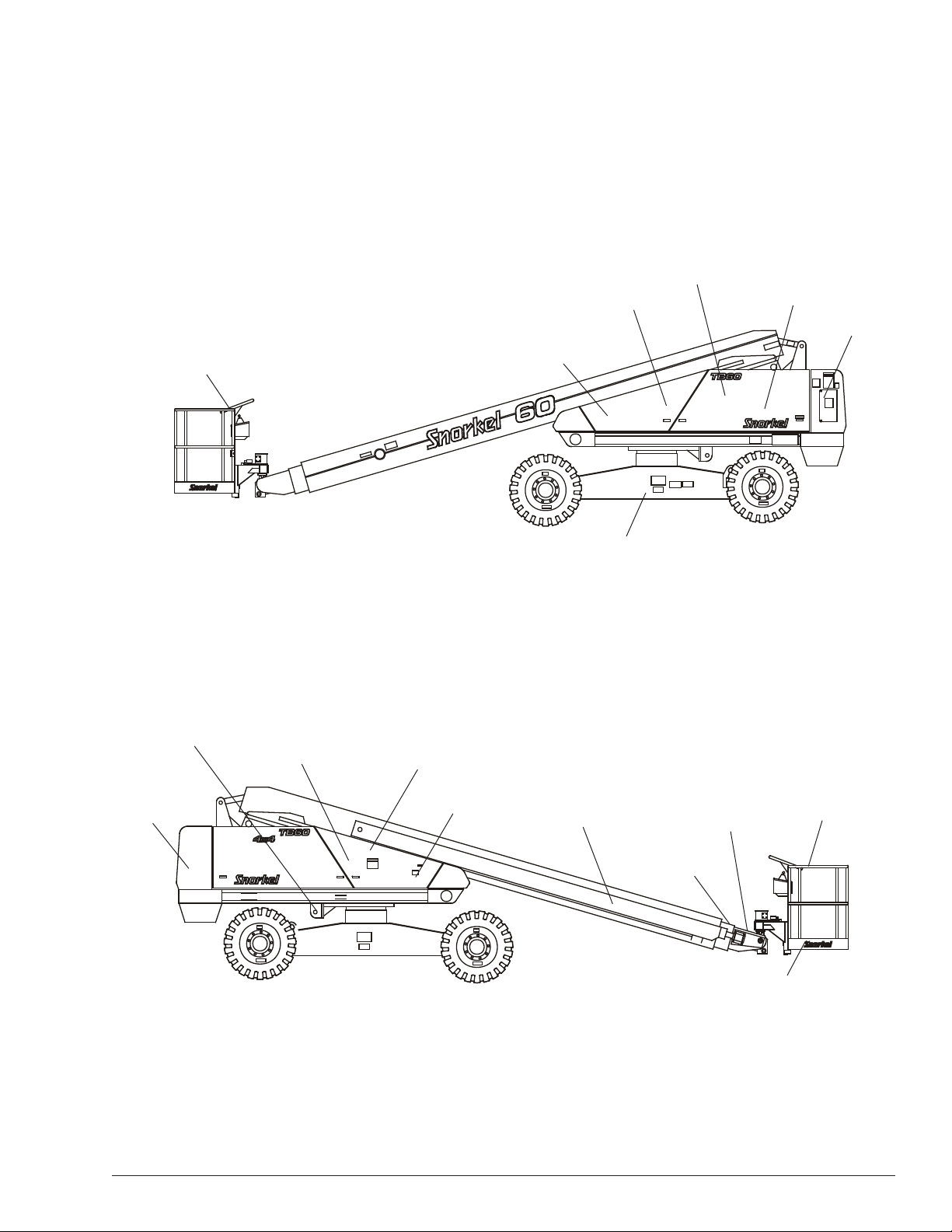
Component Identication
Chapter 3 – Specications
Fuel Tank
Operator’s
Manual
Wiring Box
Lower Controls
Upper Controls
Emergency
Lowering
Valve
Hydraulic Fluid Tank
And Filter
Battery Disconnect Switch
LP Fuel Tank
Right Side
Chassis
Steer Wheels
Engine
Steer Wheels
Batteries
Main Boom
Tip Boom
Intermediate
Boom
Platform
Platform
Foot Switch
Left Side
TB60 – 0083739 3
Page 8
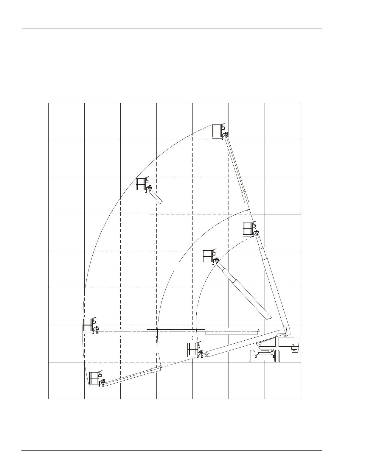
Chapter 2 – Specications
72°
16°
Working Envelope
Feet
(Meters)
70
(21.3)
60
(18.3)
50
(15.2)
40
(12.2)
30
(9.1)
20
(6.1)
10
(3)
0
10
(3)
60
(18.3)
4 TB60 – 0083739
50
(15.2)
40
(12.2)
30
(9.1)
20
(6.1)
(3)
010
10
(3)
Page 9

General Specications
Chapter 2 – Specications
Aerial Platform
Working height 66′ (20.1 m)
Maximum platform height 60′ (18.3 m)
Horizontal reach 50′ (15.2 m)
Main boom
Articulation -16° to +72°
Extension 0 to 27′ 4″ (0 to 8.33 m)
Turntable rotation 360° continuous
Turning radius, inside 15′ 5″ (4.7m)
Wheelbase 10′ (3 m)
Ground clearance 13″ (33 cm)
Maximum wheel load 10,600 lbs (4808 kg)
Maximum ground pressure 64 psi (442 kPa)
Weight, GVW
Approximate 20,700 lbs (9,389 kg)
Stowed width 8′ 5″ (2.5 m)
Stowed length 30′ 10″ (9.4 m)
Stowed height 8′ 9″ (2.7 m)
Platform
Dimensions
Standard steel 39″ x 96″ (99 cm x 243 cm)
Rated work load 500 lb (227 kg)
Optional aluminum 30″ x 60″ (76 cm x 152 cm)
Rated work load 600 lb (272 kg)
Optional aluminum 30″ x 96″ (76 cm x 244 cm)
Rated work load 500 lb (227 kg)
Optional steel 30″ x 96″ (76 cm x 244 cm)
Rated work load 500 lb (227 kg)
Rotation 90° CW to 80° CCW
Maximum number of occupants 2 people
Optional AC generator 125 VAC
Optional AC generator 220 VAC, 50 Hz
Function Speed
Turntable rotation, 360 degrees 85 to 95 seconds
Main boom
Up 40 to 50 seconds
Down 40 to 50 seconds
Extend 60 to 70 seconds
Retract 50 to 60 seconds
Platform rotation, 170 degrees 16 to 20 seconds
Drive
High, booms stowed 3.0 mph (4.8 km/h)
Low, booms elevated 1.0 mph (1.6 km/h)
Drive System
Standard Four-wheel drive
Gradeability 30%
Optional Two-wheel drive
Gradeability 25%
Tires
Foam Fillled
Highway tread,14 ply 15″ x 19.5″ (38 cm x 50 cm)
Bar lug, 4x4 12 ply 15″ x 19.5″ (38 cm x 50 cm)
Flotation, 4x4 40″ x 19-19.5″ (101.6 cm x 50 cm)
Air Fillled
Flotation 40″ x 19-19.5″ (101.6 cm x 50 cm)
Electrical System
Voltage 12 V DC negative chassis ground
Source 12 V 550 CCA battery
Fluid recommended distilled water
Hydraulic System
Maximum pressure 2,500 psi (17,250 kPa)
Reservoir capacity 26.1 US gal (99 l)
System capacity 35 US gal (132 l)
Maximum operating temperature 200°F (93°C)
Hydraulic uid recommended
Above 10°F (-12°C) Mobil DTE-13M (ISO VG32)
Below 10°F (-12°C) Mobil DTE-11M (ISO VG15)
Engine
Diesel Cummins B3.3
Deutz F4L-1011F
Deutz F4L-2011F
Kubota V2403-M-T
Gasoline and/or LPG Ford LRG 423
Ford LRG 425
General Motors 2.4L
Fuel Tank Capacity
Diesel or gasoline 40 US gal (151 l)
LPG 43.5 lbs (19.7 kg)
Dual fuel gasoline 20 US gal (76 l)
Ambient Air Temperature Operating Range
Fahrenheit 0°F to 110°F
Celsius -18°C to 43°C
Maximum Wind Speed
Gust or steady 28 mph (12.8 m/s)
TB60 – 0083739 5
Page 10

Chapter 2 – Specications
Engine Specications
Engine Displacement Fuel Grade Coolant
Diesel
Cummins
B3.3
Deutz
F4L-1011F
Deutz
F4L-2011F
Kubota
V2403-M-T
199 cu. in.
(3.26 liter)
190 cu. in.
(3.11 liter)
190 cu. in.
(3.11 liter)
148.5 cu. in.
(2.43 liter)
ASTM No. 2D fuel with a mini-
mum Cetane no. of 40.1 For op-
erating temperature below 0°C
(32°F) use winterized No. 2D.
Diesel
DIN 51 601 (February 1986).
BS 2869: A1 and A2 (with A2
refer to Deutz manual about
sulfur content)
ASTM D 975-88: 1-D and 2-D
3
CEN EN 590 or DIN EN 590
NATO Code F-54 and F-75
For operating temperatures
1
below 0°C (32°F) use winter
grade diesel.
Diesel
DIN 51 601 (February 1986).
BS 2869: A1 and A2 (with A2
refer to Deutz manual about
sulfur content)
ASTM D 975-88: 1-D and 2-D
CEN EN 590 or DIN EN 590
NATO Code F-54 and F-75
For operating temperatures
1
below 0°C (32°F) use winter
grade diesel.
Diesel
Diesel Fuel No. 2-D
ASTM D975
50% Water
50% Antifreeze
1
1
50% water
1
50% Antifreeze
Air
Air
Operating
Temperature
140°F to 212°F
2
60°C to 100°C
172°F to 203°F
78°C to 95°C
172°F to 203°F
78°C to 95°C
2
NA
Oil
Capacity
2 US gal
(7.5 liter)
2.75 US
gal (10.4
liter)
2.75 US
gal (10.4
liter)
2.51 gal
(9.5 liter)
Grade
15W-40
3
CH4/SG
API: CD
higher
API: CD
higher
CF grade
or higher
Oil
SAE
3
API
or
3
or
3
API:
3
Note 1: Refer to the engine manufacturers manual for specic fuel recommendations and specications.
Note 2: Refer to the engine manufacturers manual for specic coolant recommendations and specications.
Note 3: Refer to the engine manufacturers manual for specic lubricating oil recommendations and specications.
6 TB60 – 0083739
Page 11

Chapter 2 – Specications
Engine Displacement Fuel Grade Coolant
Ford
LRG 425
Ford
LRG 423
GM
2.4L
153 cu. in.
(2.5 liter)
140 cu. in.
(2.3 liter)
150 cu. in.
(2.4 liter)
Gasoline
Unleaded 87 or 89 octane.
Do not use gasoline blends with
more than 10% ethanol by
volume octane index of 87 or 89.
3
LPG
HD-5 USA
EN589 European
Gasoline
Unleaded gasoline 85 octane
(motor method).
LPG
Gas Processors Association
Standard 2140
Category: special duty propane
Gasoline
Unleaded 87 octane
LPG
HD-5
1
1
1
50% Water
50% Antifreeze
1
50% Water
50% Antifreeze
1
50% Water
50% Antifreeze
Operating
Temperature
195°F to 220°F
3
91°C to 104°C
160°F to 190°F
3
71°C to 88°C
176°F to 183°F
5
80°C to 84°C
Oil
Capacity
4.5 US qt
(4.26 liter)
4 US qt
(3.8 liter)
With lter:
1.12 US gal
(4.5 liter)
W/o lter:
1.18 US gal
(4.25 liter)
Grade
API: SH
3
Gasoline
API: SH
SG only if
SH is not
available
SG or SH
ILSAC
Oil
or SJ
LPG
GF-4
2
2
4
Note 1: Refer to the engine manufacturers manual for specic fuel recommendations and specications.
Note 2: Refer to the engine manufacturers manual for specic lubricating oil recommendations and specications.
Note 3: Refer to the Ford LRG 425 Operator Handbook for specic coolant recommendations and specications.
Note 4: API Starburst symbol on GF-4 oils reads “API Service SM.”
Note 5: Refer to the engine manufacturers manual for specic coolant recommendations and specications.
TB60 – 0083739 7
Page 12
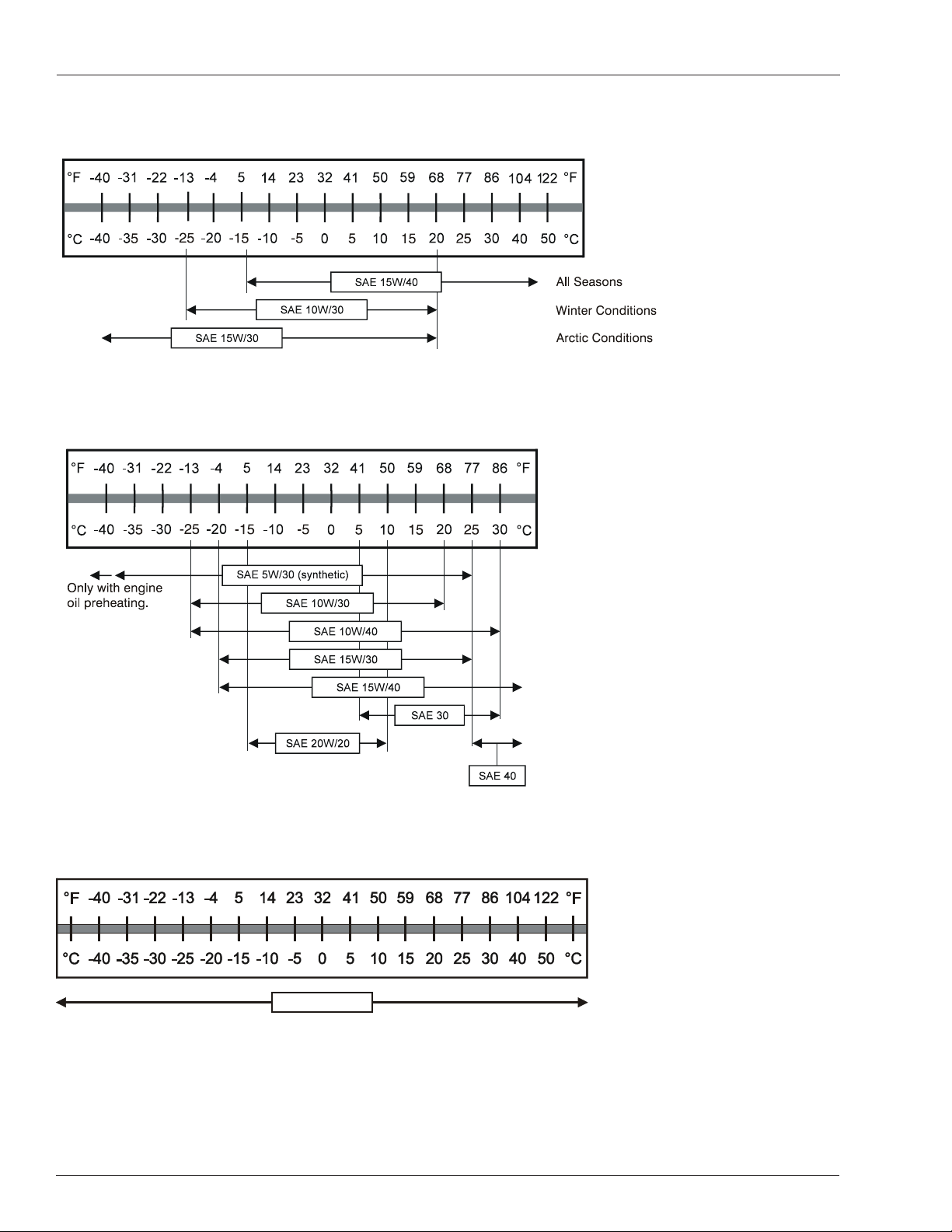
Chapter 2 – Specications
S AE 1 5W /4 0
Engine Oil Viscosity
Cummins B3.3
Deutz F4L-1011F
Deutz F4L-2011F
Kubota V2403-M-T
8 TB60 – 0083739
Page 13
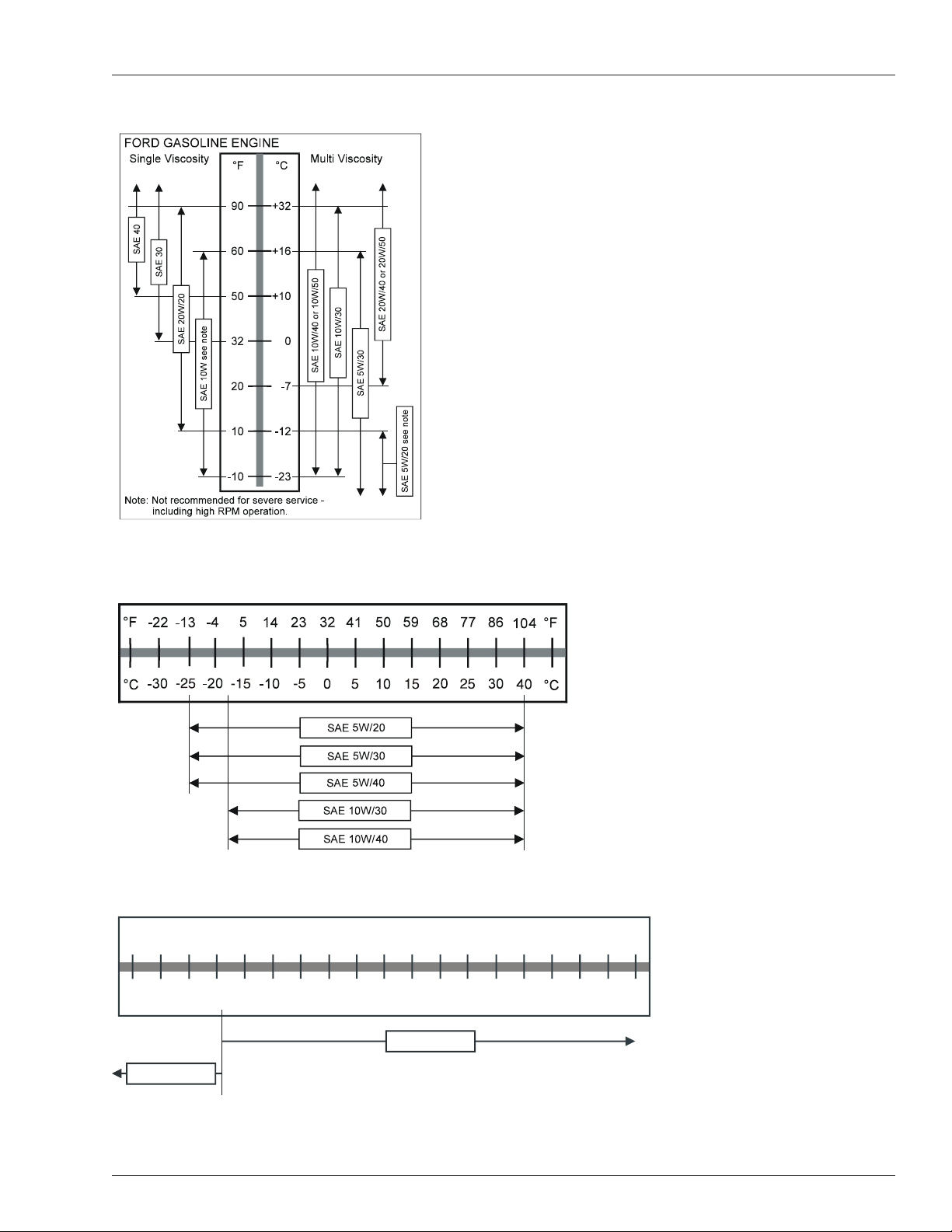
Ford LRG 423
°F
°F
-4 0
-3 1
-2 2
-1 3
-4
5
14
23 32
41
50 59 6 8 7 7 8 6 104
122
°C
°C
-4 0
-3 5
-3 0 -2 5 -2 0 -15 -1 0
-5
0
10
15 2 0 25
30
40 5 0
5
S AE 5 W /3 0
S AE 0 W /3 0
Chapter 2 – Specications
Ford LRG 425
General Motors 2.4L
Note
No straight weight oils and no specialized diesel oils are
to be used in GM engines.
TB60 – 0083739 9
Page 14

Chapter 2 – Specications
10 TB60 – 0083739
Page 15
Chapter 3 – Safety
D enotes
pro h ib ited
zon e
Knowledge of the information in this manual, and
proper training, provide a basis for safely operating the
aerial platform. Know the location of all controls and
how they operate to act quickly and responsibly in an
emergency.
Safety devices reduce the likelihood of an accident.
Never disable, modify, or ignore any safety device.
Safety alerts in this manual indicate situations where
accidents may occur.
If any malfunction, hazard or potentially unsafe condition
relating to capacity, intended use, or safe operation is suspected, stop aerial platform operation and seek assistance.
The operator bears ultimate responsibility for following
all manufacturer’s instructions and warnings, regulations
and safety rules of their employer and/or any state or
federal law.
Electrocution Hazards
The aerial platform is made of metal components and is
not insulated. Regard all conductors as energized. Do
not operate outside during a thunderstorm.
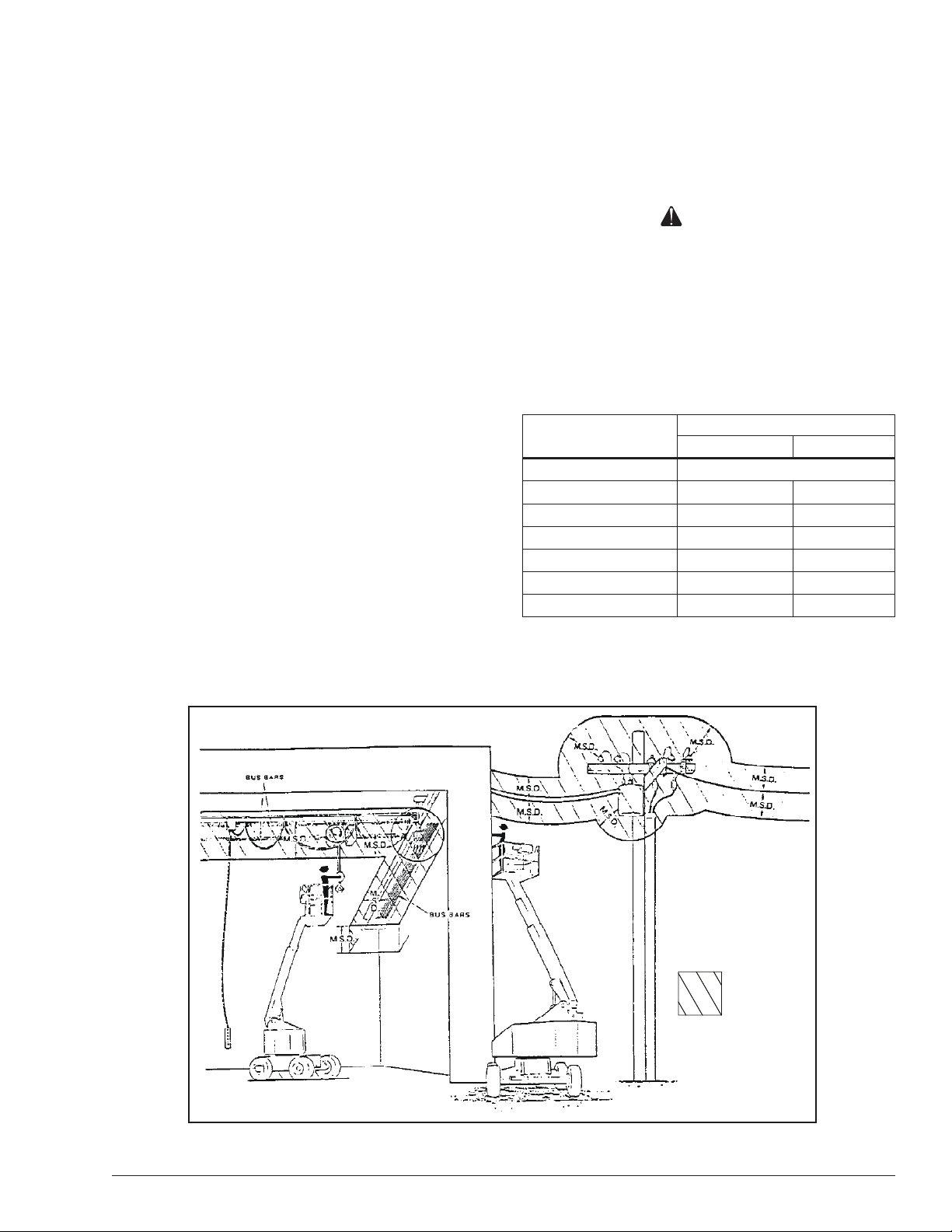
Minimum Safe Approach Distance
Minimum safe approach distances to energized power
lines and their associated parts must be observed while
operating the aerial platform.
Danger
The aerial platform is not electrically insulated.
Death or serious injury will result from contact
with, or inadequate clearance from, an energized
conductor. Do not go closer than the minimum safe
approach distance as dened by ANSI.
ANSI publications dene minimum distances that must
be observed when working near bus bars and energized
power lines. Table 1 and Figure 3 are reprinted courtesy
of Scaffold Industry Association, ANSI/SIA A92.5.
Voltage Range
(Phase to Phase)
0 to 300V Avoid Contact
Over 300V to 50kV 10 3.05
Over 50kV to 200kV 15 4.60
Over 200kV to 350Kv 20 6.10
Over 350kV to 500kV 25 7.62
Over 500kV to 750kV 35 10.67
Over 750kV to 1000kV 45 13.72
Minimum Safe Approach Distance
Feet Meters
Table 1 – Minimum Safe Approach Distance
Figure 3 – Minimum Safe Approach Distance
TB60 – 0083739 11
Page 16

Chapter 3 – Safety
Prestart Inspection
Perform a prestart inspection before each shift as described in Chapter 7. Do not use the aerial platform on
the job unless you are trained and authorized to do so.
Work Place Inspection and Practices
Do not use the aerial platform as a ground connection
when welding.
The welding ground clamp must be attached to the
same structure that is being welded.
Electrical current ow can be very intense, causing
serious internal damage to some components.
Inspect the area before and during aerial platform use.
The following are some potential hazards that may be
in the work place.
• Debris
• Slopes
• Drop-offs or holes
• Bumps and oor obstructions
• Overhead obstructions
• Unauthorized persons
• High voltage conductors
• Wind and weather conditions
• Inadequate surface and support to withstand load
forces applied by the aerial platform in all operating
congurations
Before using the aerial platform in any hazardous
(classied) location, make certain it is approved and
of the type required by ANSI/NFPA 505 for use in that
particular location.
booms, or platform. Allow sufcient room and time
to stop movement to avoid contact with structures
or other hazards.
Always look in the direction of movement.
Drive with care and at speeds compatible with the
work place conditions.
Use caution when driving over rough ground, on
slopes and when turning.
Do not engage in any form of horseplay or permit
riders any place other than in the platform.
Secure all accessories, containers, tools, and other
materials in the platform to prevent them from accidentally falling or being kicked off the platform. Remove all
objects that do not belong in or on the aerial platform.
Never steady the platform by positioning it against another platform.
Warning
The potential for an accident increases when operating an aerial platform that is damaged or malfunctioning. Death or serious injury could result from
such accidents. Do not operate the aerial platform
if it is damaged or malfunctioning.
Do not operate the aerial platform if it is damaged or not
functioning properly. Qualied maintenance personnel
must correct the problem before putting the aerial platform back into service.
Know and understand the job site trafc-ow patterns
and obey the agmen, road signs and signals.
While operating the aerial platform, a good safety
practice is to have qualied personnel in the immediate
work area to:
• Help in case of an emergency
• Operate emergency controls as required
• Watch for loss of control by platform operator
• Warn the operator of any obstructions or hazards
that may not be obvious to them
• Watch for soft terrain, sloping surfaces, drop-offs,
etc. where stability could be jeopardized
• Watch for bystanders and never allow anyone to be
under, or to reach through the booms while operating the aerial platform
Danger
Pinch points may exist between moving components.
Death or serious injury will result from becoming
trapped between components, buildings, structures,
or other obstacles. Make sure there is sufcient clearance around the machine before moving the chassis,
Operation
Use three points of support when entering or exiting
the platform. For example, use two hands and one foot
when climbing into the platform.
Never cover the platform oor grating or otherwise obstruct your view below. Make sure the area below the
platform is free of personnel before lowering.
Keep both feet positioned rmly on the platform oor.
Operate the controls slowly and deliberately to avoid
jerky and erratic operation.
Always stop the controls in neutral before going in
the opposite direction.
Do not dismount while the aerial platform is in motion
or jump off the platform.
Properly stow the aerial platform and secure it against
unauthorized operation at the end of each work day,
before transporting, or if it is left unattended.
12 TB60 – 0083739
Page 17

Chapter 3 – Safety
Tip-Over and Falling Hazards
Operate the aerial platform only on a rm, at, level
surface capable of withstanding all load forces imposed
by the aerial platform in all operating conditions. Refer to
the General Specications chart for the maximum wheel
load and ground pressure. Raise the booms only when
the aerial platform is on level ground.
Danger
The aerial platform can tip over if it becomes unstable. Death or serious injury will result from a tip-over
accident. Do not drive or position the aerial platform
for elevated use near any drop-off, hole, slope, soft
or uneven ground, or other tip-over hazard.
All platform occupants must wear a fall restraint device
connected to a lanyard anchor point.
It is best not to transfer from the platform to another
structure or from the structure to the platform, unless
that is the safest way to do the job. Judge each situation
separately taking the work environment into account. If
it is necessary to transfer from the platform to another
structure the following guidelines apply:
1. Where possible, place the platform over a roof or
walking structure to do the transfer.
2. Transfer your anchorage from one structure to the
other before stepping across.
3. Remember that you might be transferring to a structure where personal fall arrest is required.
4. Use the platform entrance, do not climb over or
through the guardrails.
Do not operate the aerial platform in windy or gusty
conditions. Do not add anything to the aerial platform
that will increase the wind loading such as billboards,
banners, ags, etc.
Never operate the aerial platform without all parts of the
guardrail system in place and the gate closed. Make
sure that all protective guards, cowlings and doors are
securely fastened.
Do not climb on the guardrails or use ladders, planks or
other devices to extend or increase the work position
from the platform.
Take care to prevent rope, electrical cords, and hoses,
etc., from becoming caught in or on the aerial platform.
If the platform or booms becomes caught on an ad-
jacent structure or other obstacle and is prevented
from normal motion, reverse the control to free the
platform.
If control reversal does not free the platform, evacu-
ate the platform before attempting to free it.
Electrical System
Charge the batteries in a well-ventilated area free of
ame, sparks or other hazards that might cause re or
explosion.
Do not operate any of the aerial platform functions while
the battery charger is plugged in.
Warning
Batteries give off hydrogen and oxygen that can
combine explosively. Death or serious injury could
result from a chemical explosion. Do not smoke or
permit open ames or sparks when checking the
batteries.
Battery acid can damage the skin and eyes. Serious
infection or reaction can result if medical treatment
is not given immediately. Wear face and eye protection when working near the batteries.
Batteries contain sulfuric acid that can damage your
eyes or skin on contact.
Wear a face shield, rubber gloves, and protective
clothing when working around batteries.
If acid contacts your eyes, ush immediately with
clear water and get medical attention.
If acid contacts your skin, wash off immediately with
clear water.
Do not exceed the platform capacity as indicated on
the platform rating placard on the platform. Do not carry
loads that extend beyond the platform guardrails without
prior written consent from Snorkel.
Do not operate the aerial platform from trucks, trail-
ers, railway cars, oating vessels, scaffolds or similar
equipment unless the application is approved in writing
by Snorkel.
Do not use the aerial platform as a crane, hoist, jack or
for any purpose other than to position personnel, tools
and materials.
TB60 – 0083739 13
Hydraulic System
The hydraulic system contains hoses with hydraulic uid
under pressure.
Danger
Hydraulic uid escaping under pressure can have
enough force to inject uid into the esh. Serious
infection or reaction will result if medical treatment
is not given immediately. In case of injury by escaping hydraulic uid, seek medical attention at once.
Page 18

Chapter 3 – Safety
Do not place your hand or any part of your body in front
of escaping hydraulic uid. Use a piece of cardboard or
wood to search for hydraulic leaks.
Engine and Fuel Handling Precautions
Refer to the engine manufacturer’s Operator’s Manual
for complete information on safe engine operation,
maintenance and specications.
Danger
Engine exhaust contains carbon monoxide, a poisonous gas that is invisible and odorless. Breathing
engine exhaust fumes will cause death or serious
illness. Do not run the engine in an enclosed area
or indoors without adequate ventilation.
Operate dual fuel machines on LPG fuel when indoors
to reduce exhaust fumes and carbon monoxide.
Be careful not to run the diesel fuel tank empty. Bleed
the fuel system if air enters the lines between the tank
and the injection pump.
Allow the engine to return to idle before shutting the
engine off.
Do not smoke or permit open ames while fueling or
near fueling operations.
Never remove the fuel cap or ll the fuel tank while the
engine is running or hot. Never allow fuel to spill on hot
machine components.
Maintain control of the fuel ller nozzle when lling the
tank. Spilled fuel is a potential re hazard.
Do not overll the fuel tank. Allow room for expansion.
Clean up spilled fuel immediately.
Tighten the fuel tank cap securely. If the fuel cap is lost,
replace it with an approved cap from Snorkel. Use of a
non-approved cap without proper venting may result in
pressurization of the tank.
Never use fuel for cleaning purposes.
For diesel engines, use the correct fuel grade for the
operating season.
Caution
Engine coolant escaping under pressure may cause
serious burns. Shut the engine off and let it cool
before removing the radiator cap.
Let the engine and radiator cool before adding coolant.
Placards and Decals
The aerial platform is equipped with placards and decals that provide instruction for operation and accident
prevention. Do not operate the aerial platform if any
placards or decals are missing or not legible.
14 TB60 – 0083739
Page 19
Chapter 4 – Safety Devices
This aerial work platform is manufactured with safety
devices, placards, and decals to reduce the likelihood
of an accident.
For the safety of all personnel, do not disable, modify,
or ignore any safety device.
On older machines the emergency stop is a two-
position toggle switch with a red safety guard.
Push the guard down over the toggle switch to dis-
connect power to all control circuits. Lift the guard
and push the switch up to restore power.
Safety devices are included in the daily prestart
inspection.
Warning
The potential for an accident increases when safety
devices do not function properly. Death or serious
injury could result from such accidents. Do not alter,
disable, or override any safety device.
If any safety devices are defective, remove the aerial
platform from service until qualied maintenance personnel can make repairs.
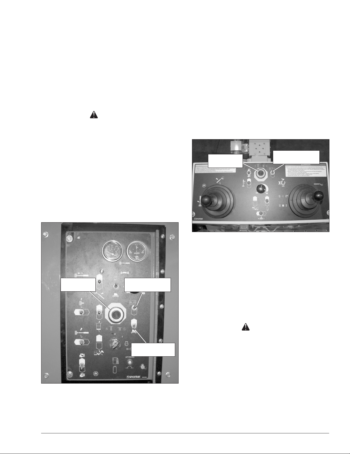
Emergency Stop Controls
There is an emergency stop control at the lower and
upper controls.
At the lower controls, the emergency stop button is a
two-position push button (refer to Figure 4.1).
Note
The lower controls override the upper controls. If the upper control emergency stop button is engaged, the lower
controls can still be used to operate the aerial platform.
At the upper controls, the emergency stop is a two-posi-
tion push button (refer to Figure 4.2).
Emergency
Stop Button
Engine/Emergency
Power Switch
Figure 4.2 – Upper Controls
Push the emergency stop button inward to discon-
nect power to the upper control circuits.
Emergency
Stop Button
Engine/Emergency
Power Switch
Ground Operation
Switch
Figure 4.1 – Lower Controls
Push the emergency stop button inward to discon-
nect power to all control circuits.
Pul l the bu tto n ou twa rd to r estore po wer.
Pull the button outward to restore power.
Emergency Power System
The emergency power system includes a back-up pump,
motor, and battery. Use this system to operate the boom
and turntable functions to lower the platform if the main
power system fails due to engine or pump failure.
Caution
The emergency power system is for emergency
lowering and stowing only. The length of time the
pump can be operated depends on the capacity
of the battery. Do not use this system for normal
operation.
Hold the engine/emergency power switch (refer to
Figure 4.1 and 4.2) downward to activate the emergency power system.
Release the switch to disengage the emergency
power system.
The length of time the pump can be operated de-
pends on the capacity of the battery.
TB60 – 0083739 15
Page 20
Chapter 4 – Safety Devices
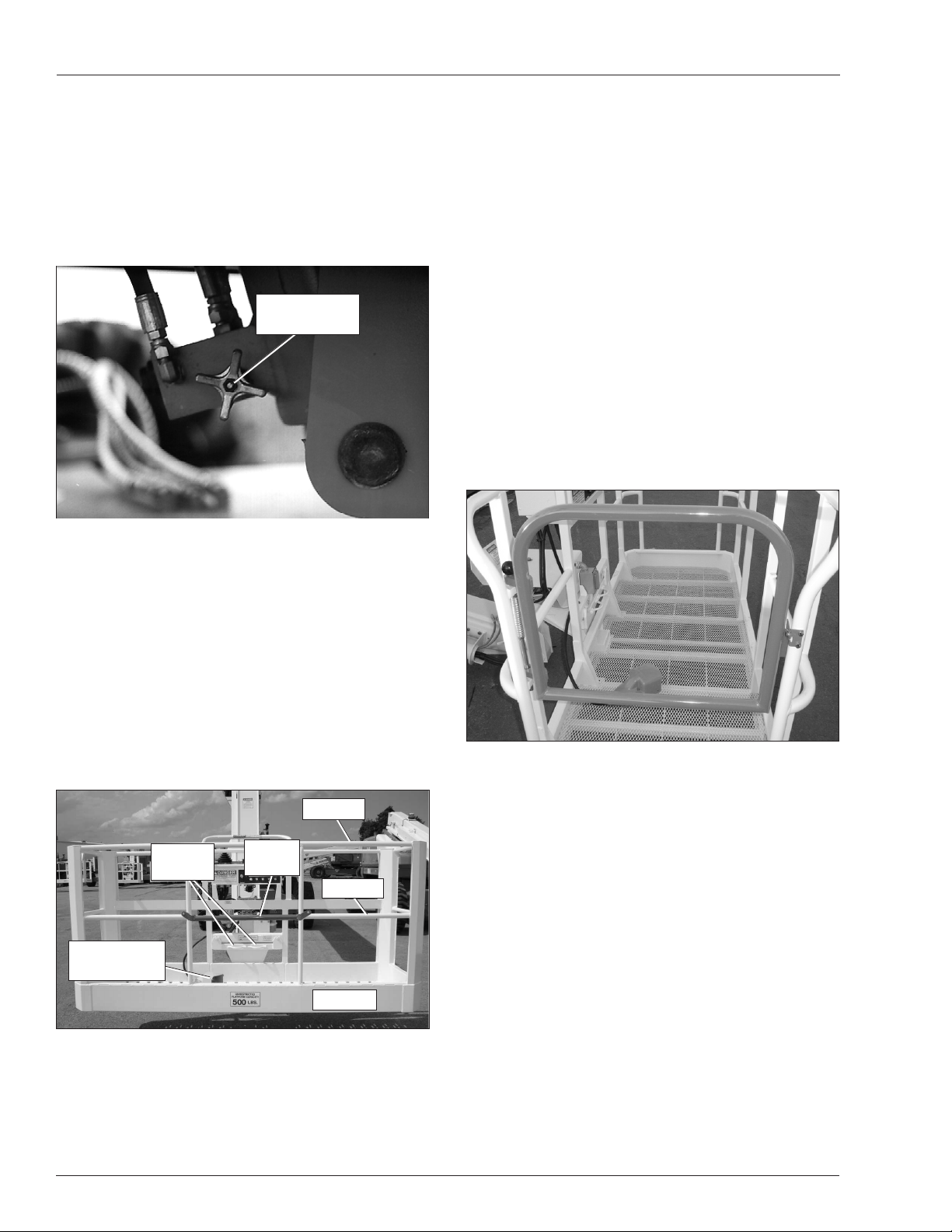
Emergency Lowering Knob
The emergency lowering knob may be used to lower
the booms if the engine will not start and the emergency
power system will not work.
The knob is on the base end of the main boom lift
cylinder (refer to Figure 4.3) under the left side of the
turntable.
Emergency
Lowering Knob
Figure 4.3 – Emergency Lowering Knob
Guardrails
The guardrails (refer to Figure 4.5) help protect personnel from falling off the platform.
The guardrail system includes:
A top rail
A mid rail
A gravity gate or optional swinging gate
Optional side entry gravity gate
Toeboards around the sides of the platform.
The gravity gate(s) allow for access to the platform and
close automatically after entering or exiting the platform.
After entering the platform check to make sure the gates
are fully lowered and even with the mid rail.
The optional swinging gate (refer to Figure 4.5) allows
for access to the platform. The gate must be securely
latched except when personnel are entering or leaving
the platform.
Ground Operation Switch
The ground operation switch (refer to Figure 4.1) prevents boom and platform movement if a control switch
on the lower control panel is accidentally moved.
Hold the switch up to operate the machine from the
lower controls.
Platform Foot Switch
Step down on the platform foot switch (refer to Figure
4.4) to activate the upper controls.
Top Rail
Lanyard
Anchors
Platform Foot
Switch
Figure 4.4 – Platform
The foot switch must be engaged and a control must be
moved to operate the boom, drive and/or platform from
the upper controls.
Gravity
Gate
Mid Rail
Toeboard
Figure 4.5 – Platform Swing Gate
Lanyard Anchors
Two lanyard anchors for fall restraint anchorage are
provided below the upper controls at the front of the
platform (refer to Figure 4.4).
Note
The lanyard anchors are not designed for lifting or tying
the machine down.
All personnel in the platform must connect their fall
restraint device to a lanyard anchor before raising
the platform.
Attach only one fall restraint device to each lanyard
anchor.
Do not use the aerial platform for personal fall arrest
anchorage.
16 TB60 – 0083739
Page 21
Ground Fault Circuit Interrupter
The electrical power outlet at the platform (refer to Figure
4.6) contains a ground fault circuit interrupter (GFCI) to
provide protection for personnel.
Electrical
Power Outlet
Figure 4.6 – Electrical Outlet
Tilt Alarm
If the aerial platform chassis is out of level more than
ve degrees when the main boom is raised or extended,
an alarm will sound. The tilt alarm is located under the
upper control panel.
Chapter 4 – Safety Devices
Engine
Temperature
Gauge
Figure 4.7 – Lower Control Panel
Danger
The aerial platform can tip over if it becomes unstable. Death or serious injury will result from a tip-over
accident. Do not drive or position the aerial platform
for elevated use near any drop-off, hole, slope, soft
or uneven ground, or other tip-over hazard.
Completely retract and lower the main boom and then
drive to a level surface when the tilt alarm sounds.
The tilt alarm is for added protection and does not
justify operating on anything other than rm, at, level
surfaces.
Engine Protection Systems
A constant alarm will sound to warn against high engine
temperature or low oil pressure.
The engine will shut-down
if the operating temperature exceeds a preset level
or if the oil pressure is too low for safe operation.
An engine temperature gauge is on the lower control
panel (refer to Figure 4.7).
High Engine Temperature Alarm
If the coolant in a Cummins or GM engine exceeds the
engine operating temperature an alarm will sound and
the engine will shut off.
If the oil in a Deutz engine exceeds 230°F (110°C) an
alarm will sound and the engine will shut off. Any time
there is no alternator current being produced, an alarm
will sound and the engine will shut off. This prevents
high engine temperature if the fan belt breaks.
Do not restart the engine until the condition that caused
the overheating has been corrected.
Low Oil Pressure Alarm
The low oil pressure alarm sounds when the engine oil
pressure is near the lower limit for safe engine operation.
If the alarm sounds, lower the platform to the ground
and then turn the engine off.
If the engine oil pressure falls below a safe operating
value the engine will shut off.
The engine can be restarted with low oil pressure,
but it will only run for a few seconds before it shuts
off again.
Do not restart the engine until the condition that
caused the low oil pressure has been corrected.
TB60 – 0083739 17
Page 22
Chapter 4 – Safety Devices
Horn
An optional horn may be used to warn personnel on
the ground. The horn button is on the right side of the
upper control box.
The horn is operational when the emergency stop button and the start switches are both on, at the lower and
the upper controls.
All Motion Alarm
An optional all motion alarm may be provided on the
machine. The alarm sounds, in short beeps, anytime the
machine functions are being operated. The alarm is used
to warn personnel in the work area to stand clear.
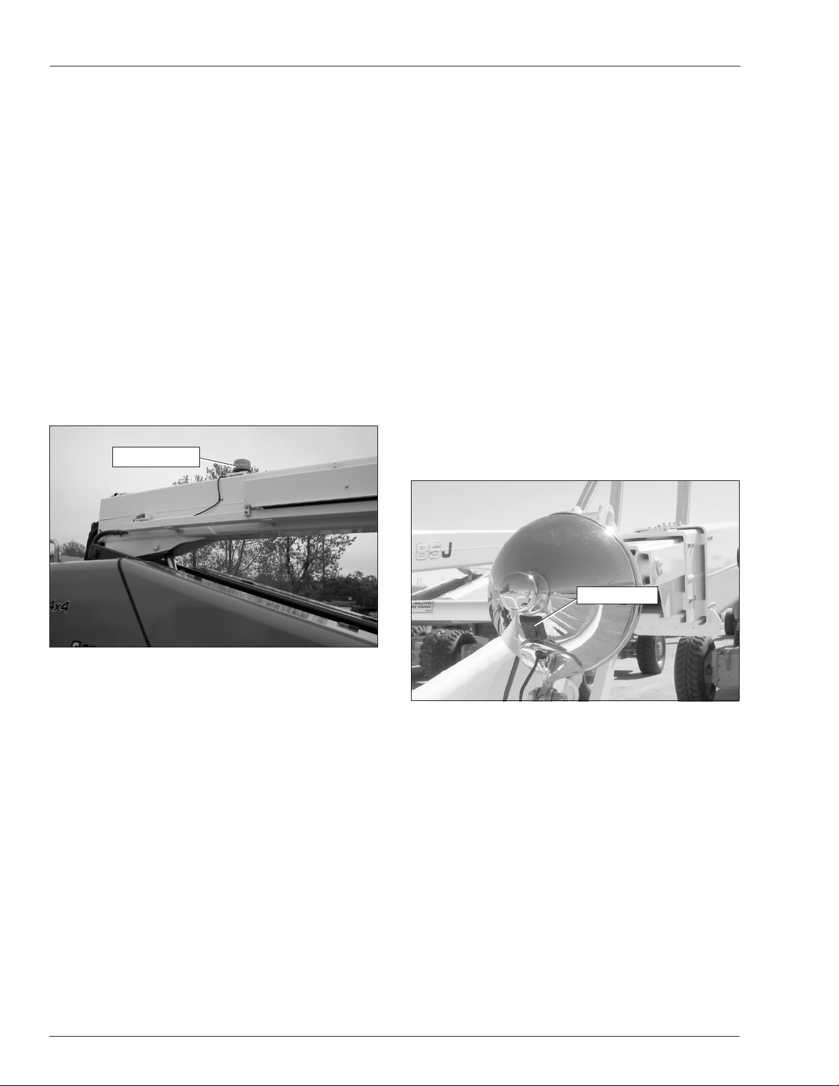
Flashing Light
An optional amber ashing light may be located on
the top of the boom near the base end (refer to Figure
4.8). The ashing light warns personnel that the aerial
platform is in the area.
Flashing Light
Driving Lights
The optional headlights and blinking tail lights may be
used to help improve visibility while driving the aerial
platform and help others see it too.
The headlights are located on the top of the front
cowling.
The tail lights are mounted on the sides of the rear
cowling.
Do not use the driving lights to drive on public
roadways.
Platform Work Lights
The optional platform work lights may be used to help
improve visibility while working aloft in dimly lit areas.
The platform work lights are located on the top rail of
the platform, one on each side of the upper control
panel (refer to Figure 4.9).
Do not use the platform work lights to drive on public
roadways.
Figure 4.8 – Flashing Light
The light ashes at about one ash per second when
the engine is running.
Light Switch
Figure 4.9 – Platform Work Lights
Bump Guard System
The optional bump guard system is a spring mounted
padded railing below the platform. There are two infrared
lights mounted along the bottom of the platform next
to two infrared sensitive switches. The lights shine on
reectors on the bump guard system and are reected
back to the switches.
If the bump guard comes into contact with a stationary
object, the bump guard moves and one or both of the
light beams is broken, immediately stopping all platform
movement.
18 TB60 – 0083739
Page 23
Chapter 5 – Gauges and Displays
The aerial platform is equipped with several gauges to
monitor the condition of the machine before and during
operation.
Hour Meter
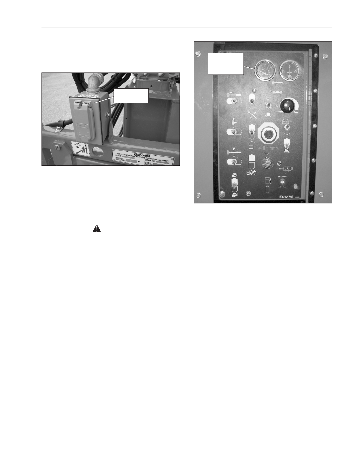
The hour meter is located on the wiring box on the left
side of the lower controls (refer to Figure 5.1). It measures the accumulated engine operating time.
Hour
Meter
Figure 5.1 – Wiring Box
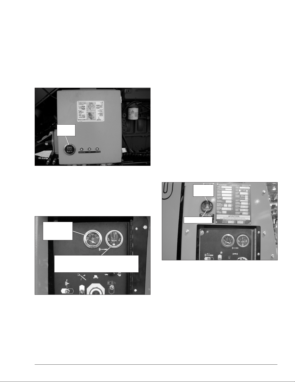
Engine Temperature Gauge
The temperature gauge is located on the lower control
panel (refer to Figure 5.2).
Ammeter – Cummins, Deutz and Ford Engines
The ammeter is located on the lower control panel (refer
to Figure 5.2). The ammeter displays the level of current
ow from the alternator to the batteries.
After the engine has been running for a few minutes
under normal operating conditions, the ammeter
gauge indicator should read “0.”
Machines with Kubota engines do not have an engine
ammeter gauge.
Voltmeter – General Motors Engines
The voltmeter is located on the engine gauge panel
above the lower controls. The voltmeter displays battery voltage.
After the engine has been running for a few minutes
under normal operating condition, the voltmeter
should indicate between 12.5 and 14 volts.
Engine Air Filter Gauge
The air lter gauge (refer to Figure 5.3) is located on the
engine gauge panel above the lower controls.
Air Filter
Gauge
Machines with Kubota engines do not have an engine
temperature gauge.
Engine
Temperature
Gauge
Ammeter – Cummins, Deutz,
and Ford Engines
Voltmeter – General Motors Engines
Figure 5.2 – Lower Controls
The gauge on liquid cooled engines shows the
temperature of the water and antifreeze mixture in
the engine block.
The gauge on air cooled engines shows the temper-
ature of the engine oil as the oil leaves the lter.
Reset Button
Figure 5.3 – Air Filter Gauge
The air lter gauge measures the air pressure between
the intake manifold and the air lter.
The yellow indicator disk inside the sight glass stays
at its highest level when the engine is turned off.
When the yellow indicator disk reaches the red area,
it’s time to change the lter element.
After changing the lter, press the reset button to reset
the indicator disk to the bottom of the sight glass.
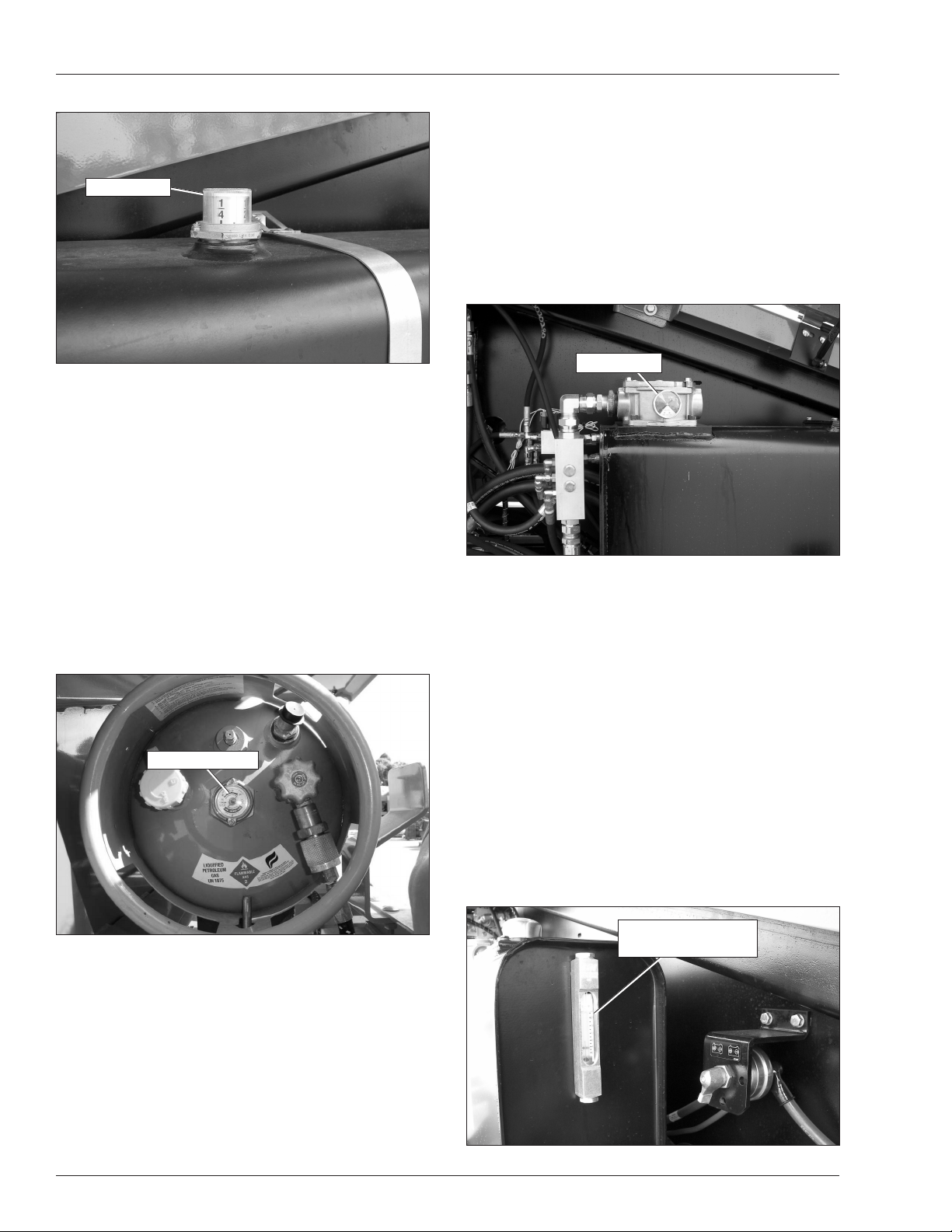
Fuel Gauge
The fuel gauge is located on top of the diesel or gasoline
tank (refer to Figure 5.4). Access the gauge by opening
the door on the right side of the chassis.
TB60 – 0083739 19
Page 24
Chapter 5 – Gauges and Displays
Fuel Gauge
Hydraulic Fluid Filter Gauge
The uid lter gauge (refer to Figure 5.6) is located on the
return line lter on the top of the reservoir. The reservoir
is behind the door on the left side of the turntable.
During high pump ow situations, the gauge indi-
cates the condition of the lter.
When the needle on the gauge is in the red zone,
its time to change the lter.
Figure 5.4 – Fuel Tank
Read the fuel gauge at the line in the clear plastic
window.
The gauge indicates the fuel tank level in fractions
of a full tank.
Note
Do not run a diesel fuel tank empty. Air in the fuel line
makes the engine hard to start.
LPG tanks have a fuel gauge that has two scales. One
scale measures the fuel level when the tank is mounted
vertical and the other is used when the tank is mounted
horizontal (refer to Figure 5.5).
Horizontal Scale
Filter Gauge
Figure 5.6 – Hydraulic Fluid Filter Gauge
Fluid Level and Temperature Gauge
A sight gauge on the right side of the hydraulic reservoir
displays the level and temperature of the hydraulic uid
(refer to Figure 5.7). The reservoir is behind the door on
the left side of the machine.
Only read the uid level when the aerial platform is in the
stowed position, booms completely down and retracted.
Otherwise, the cylinders act as large reservoirs for hy-
draulic uid making the level appear too low.
The fluid should be between the minimum and
maximum lines.
If the temperature rises above 200°F (93°C) stop
machine operation and let the uid cool before resuming operation.
Fluid Level and
Figure 5.5 – LPG Tank
The LPG tank is mounted horizontally behind the
Temperature Gauge
rear cowling door on the right side of the machine.
Read the horizontal scale to determine the fuel level.
Engine Oil
The engine oil level is measured with a dipstick. The
dipstick is the only way to accurately determine the
engine oil level. The engine oil level should always be
between the add and full marks on the dipstick.
20 TB60 – 0083739
Figure 5.7 – Hydraulic Fluid Filter Gauge
Page 25
Chapter 6 – Controls
Danger
Pinch points may exist between moving components. Death or serious injury can result from being
trapped between components, buildings, structures,
or other obstacles. Make sure all personnel stand
clear while operating the aerial platform.
Controls to position the platform are located on the
lower control panel on the turntable and on the upper
control panel in the platform.
Controls to drive the aerial platform are located on
the upper control panel only.
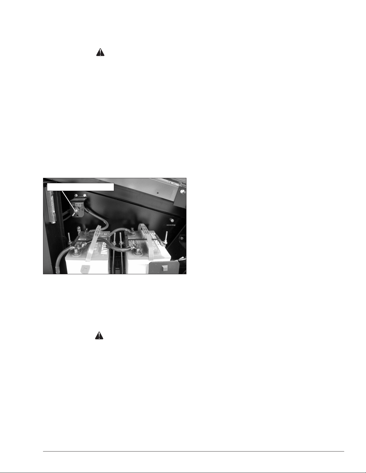
Battery Disconnect Switch
The battery disconnect is located behind the door on
the left side of the turntable above the batteries (refer
to Figure 6.1).
Battery Disconnect Switch
The following are located on the lower control panel.
• Emergency stop button
• Control selector switch
• Start switch
• Ground operation switch
• Rotation switch
• Boom elevation switch
• Boom extend/retract switch
• Boom speed knob
• Platform level switch
• Platform rotation switch
• Engine/emergency power switch
• Throttle switch
• Fuel switch (dual fuel machines)
Emergency Stop Button
The emergency stop button
two-position, red push button.
Push the button inward to disconnect power to all
(refer to Figure 6.2)
is a
control circuits.
Pull the button outward to restore power.
On older machines, the emergency stop is a two-position
toggle switch with a red safety guard.
Figure 6.1 – Battery Disconnect Switch
The battery disconnect removes electrical power from all
electrically controlled functions when in the off position.
Place the switch in the on position to electrically
connect the battery to the electrical system.
Caution
Only authorized personnel should operate the aerial
platform. Unqualied personnel may cause injury
to coworkers or property damage. Lock the battery
disconnect switch in the off position before leaving
the aerial platform unattended.
Turn the battery disconnect switch off to prevent
unauthorized use of the aerial platform.
Lower Controls
The lower controls (refer to Figure 6.2) are located on the
right side of the turntable. Boom and platform functions
can be operated from the lower controls.
Push the guard down over the toggle switch to dis-
connect power to all control circuits
Lift the guard and push the toggle switch up to re-
store power.
Control Selector Switch
Use the control selector switch (refer to Figure 6.2)
to select between the lower control and upper control
operation.
Push the switch upward to operate the aerial platform
from the upper controls.
Push the switch downward to operate the aerial
platform from the lower controls.
Start Switch
The start switch (refer to Figure 6.2) works like an automobile ignition switch.
Hold the switch in the start position until the engine
starts, then release it to on.
If the engine dies, the switch must be turned to off
before it can be turned back to start.
An alarm sounds, when the switch is turned on, to warn
others that the machine engine is being started.
TB60 – 0083739 21
Page 26

Chapter 6 – Controls
Boom Extend/Retract
Switch
Boom Elevation
Switch
Control Selector
Switch
Boom Speed
Knob
Emergency Stop Button
Platform Rotation
Switch
Platform Level Switch
Rotation Switch
Throttle Switch
Figure 6.2 – Lower Controls
Note
On some machines it may be necessary to pause about
three seconds in the on position before going to start so
the starter can engage.
If the platform is to stay in a particular position for a long
time, turn the start switch to off to shut off the engine
and save fuel.
Engine/Emergency
Power Switch
Ground Operation
Switch
Start Switch
Circuit Breaker Reset Button
Boom Elevation Switch
The boom elevation switch (refer to Figure 6.2) is used
to raise or lower the main boom. The switch is spring
returned to the center off position.
Hold the switch up to raise the main boom.
Hold the switch down to lower the main boom.
Ground Operation Switch
The ground operation switch (refer to Figure 6.2) is used
to operate the machine from the lower controls. The
switch is spring returned to the off position.
Hold the ground operation switch upward continually
Boom Extend/Retract Switch
The boom extend/retract switch (refer to Figure 6.2) is
used to extend or retract the booms. The switch is spring
returned to the center off position.
Hold the switch to the left to extend the tip boom.
to operate the machine from the lower controls.
Hold the switch to the right to retract the tip boom.
The engine speed increases when the switch is
held upward.
Boom Speed Knob
The boom speed knob (refer to Figure 6.2) is used to
Rotation Switch
control the speed of the following boom functions:
The rotation switch (refer to Figure 6.2) is used to rotate the turntable in a clockwise or counterclockwise
direction. The switch is spring returned to the center
Main boom raise/lower
Boom extend/retract
off position.
Set the knob to slow when beginning a movement. The
Hold the switch to the right to rotate the turntable
counterclockwise.
speed may be increased by slowly rotating the knob
toward fast. For smooth operation, rotate the knob to
slow when ending movement.
Hold the switch to the left to rotate the turntable
clockwise.
22 TB60 – 0083739
Page 27

Chapter 6 – Controls
Platform Level Switch
The platform level switch (refer to Figure 6.2) is used to
level the platform oor with respect to the ground. The
switch is spring returned to the center off position.
Hold the switch upward to tilt the platform oor up-
ward or away from the ground.
Hold the switch downward to tilt the platform oor
downward or toward the ground.
Platform Rotation Switch
The platform rotation switch (refer to Figure 6.2) is used
to rotate the platform relative to the end of the tip boom.
The switch is spring returned to the center off position.
Hold the switch to the right to rotate the platform
counterclockwise.
Hold the switch to the left to rotate the platform
clockwise.
Engine/Emergency Power Switch
The engine/emergency power switch (refer to Figure 6.2)
is used to operate turntable, boom, and platform functions using the emergency power system. The switch is
spring returned to the engine position for aerial platform
engine operation.
Caution
The emergency power system is for emergency
lowering and stowing only. The length of time the
pump can be operated depends on the capacity
of the battery. Do not use this system for normal
operation.
Hold the engine/emergency power switch downward
to activate the emergency power system.
Release the switch to disengage the emergency
power system.
Note
The emergency power system is for lowering the platform during an emergency and is not intended for normal
machine operation.
If the engine is running, it will stop when the switch is
placed in the emergency power position.
Throttle Switch
The throttle switch (refer to Figure 6.2) is used to set the
engine throttle speed to either low or high idle.
Place the switch in the low position before starting
the engine.
The engine has a two speed throttle operation from the
lower controls.
Place the throttle switch is in the low position to idle
the engine.
Place the switch in the high position to increase the
engine speed to mid-range.
Placing the ground controls switch in the on position
also increase the engine speed to mid-range
Fuel Switch
Engines on machines with the dual fuel option can be
operated using gasoline or liqueed petroleum gas
(LPG). Dual fuel machines have a gasoline tank and
an LPG tank behind the door on the right side of the
turntable.
The fuel switch may be used to select between gasoline
and LPG operation.
Place the switch downward to operate the engine
using gasoline.
Place the switch upward to operate the engine us-
ing LPG.
Hydraulic System Warm-up Switch
The optional hydraulic uid warm-up switch is used to
warm the hydraulic uid when the ambient temperature
is below 32°F (0°C) and boom movement is sluggish
because of cold uid.
Caution
Not all hydraulic uid is suitable to use in the hydraulic system. Some have poor lubricating char-
acteristics and may increase component wear. Only
use hydraulic uid as recommended.
Use cold weather hydraulic oil as recommended in the
machine General Specications in temperatures of 10°F
(-12°C) or below.
The toggle switches for the warm-up system are on
the lower control panel and on the front of the upper
control panel.
Note
Machine functions are not operational while using the
hydraulic warm-up system.
To warm-up the hydraulic uid from the lower controls:
1. Start the engine from the lower controls.
Place the switch in the high position for machine
operation and for engine and/or hydraulic system
2. Place the hydraulic uid warm-up switch in the on
position.
warm-up.
TB60 – 0083739 23
Page 28

Chapter 6 – Controls
The engine throttle speed will increase to warm
the hydraulic uid.
The engine throttle speed will decrease and return
to idle once the hydraulic uid reaches a preset
temperature.
If the warm-up switch is left on the engine speed
will continue to increase and decrease to keep the
hydraulic uid at a preset temperature.
3.
When the engine throttle speed returns to idle, place
the hydraulic uid warm-up switch in the off position.
Circuit Breaker Reset Button
Circuit Breaker Reset Buttons
The wiring box has a circuit breaker for the main and run
circuits. There is a reset button for each circuit breaker
on the front of the wiring box (refer to Figure 6.3).
Circuit Breaker Reset Buttons
Figure 6.3 – Wiring Box
The upper control panel has a circuit breaker for the
swing (turntable rotation), lift, drive and main control
circuits. The circuit breakers are on the front of the up-
per control panel (refer to Figure 6.4).
Circuit Breaker Reset Buttons
Figure 6.5 – Electrical Power Outlet
The circuit breakers protect the electrical wiring and
components from electrical overload in case of a short
circuit or other fault.
Caution
A tripped circuit breaker indicates a malfunction in
the electrical system. Component damage can result
if the cause of the malfunction is not corrected. Do
not operate the aerial platform if the circuit breaker
trips repeatedly.
Push the button to reset the circuit breaker.
Upper Controls
The upper controls (refer to Figure 6.6) are located on the
control panel at the platform. Boom, platform, and drive
functions can be operated from the upper controls.
The following controls are located on the upper control
panel.
• Start switch
• Emergency stop button
• Boom joystick
• Boom extension switch
• Boom speed knob
• Drive joystick
• Drive range switch
• Platform level switch
• Platform rotate switch
• Engine/emergency power switch
• Throttle switch
• Hydraulic system warm-up (option)
Start Switch
Start Switch
The engine can be started from the platform using the
anti-restart master switch on the front of the upper con-
trol panel (refer to Figure 6.6). This switch is similar to
Figure 6.4 – Upper Control Panel Front
The electrical power outlet at the platform has a 15 amp
circuit breaker. The reset button is on the right side of
an automobile ignition switch.
Turn the switch to start until the engine starts, then
release it to on.
the electrical box (refer to Figure 6.5).
24 TB60 – 0083739
Page 29

If the engine dies, the switch must be turned to off
before it can be turned back to start.
An alarm sounds when the switch is turned on to warn
others that the machine engine is being started.
Chapter 6 – Controls
Drive Joystick
The drive joystick (refer to Figure 6.6) is used to control
forward and reverse motion of the aerial platform. It is
also used to steer the machine. The steering and drive
functions may be operated simultaneously.
Note
On some machines it may be necessary to pause about
three seconds in the on position before going to start so
the starter can engage.
If the platform is to stay in a particular position for a
long time, turn the switch to off to shut off the engine
and save fuel
Emergency Stop Button
The emergency stop is a two-position, red push button on
the top of the upper control panel (refer to Figure 6.6).
Push the button inward to disconnect power to all
control circuits at the upper controls.
Pull the button outward to restore power.
Note
The lower controls override the upper controls. If the upper control emergency stop button is engaged the lower
controls can still be used to operate the aerial platform.
Push the emergency stop button inward when the
upper controls are not in use to protect against unintentional operation.
Note
The distance the joystick is moved is proportional to the
speed of the function.
To move the aerial platform forward, hold the joystick
forward as indicated by the directional arrows on
the chassis.
To move the aerial platform backward, hold the
joystick backward as indicated by the directional
arrows on the chassis.
To steer to the right, hold the joystick to the right as
indicated by the directional arrows on the chassis.
To steer to the left, hold the joystick to the left as
indicated by the directional arrows on the chassis.
Note
The steering wheels are not self-centering. Set the steering wheels straight ahead after completing a turn.
Drive Range Switch
The drive range switch (refer to Figure 6.6) has two
positions to select drive wheel operation:
Boom Joystick
Emergency Stop
Throttle
Switch
Boom Extension Switch
Start Switch
Button
Engine/Emergency
Power Switch
Drive Range
Switch
Drive Joystick
Boom Speed Knob
Platform Level
Switch
Platform Rotation
Switch
Figure 6.6 – Upper Controls
TB60 – 0083739 25
Page 30

Chapter 6 – Controls
•
High range – high speed and low torque operation.
•
Low range – low speed and high torque operation.
Boom Joystick
The boom joystick (refer to Figure 6.6) is used to raise
and lower the main boom and to rotate the turntable.
The boom and turntable functions may be operated
simultaneously.
Note
The distance the joystick is moved is proportional to the
speed of the function.
Hold the joystick forward to raise the main boom and
backward to lower the boom.
Hold the joystick to the right to rotate the turntable
counterclockwise and to the left to rotate the turntable clockwise.
Boom Extension Switch
The boom extension switch (refer to Figure 6.6) is used
to extend or retract the tip and intermediate booms. The
switch is spring returned to the center off position.
Hold the switch backward to extend the booms.
Hold the switch forward to retract the booms.
Platform Level Switch
The platform level switch (refer to Figure 6.6) is used to
level the platform oor with respect to the ground. The
switch is spring returned to the center off position.
Hold the switch forward to tilt the platform oor up-
ward or away from the ground.
Hold the switch backward to tilt the platform oor
downward or toward the ground.
Platform Rotation Switch
The platform rotation switch (refer to Figure 6.6) is used
to rotate the platform relative to the end of the tip boom.
The switch is spring returned to the center off position.
Set the knob to slow when beginning a boom movement.
The speed may be increased by slowly rotating the knob
toward fast. For smooth operation, rotate the knob to
slow when ending boom movement.
Throttle Switch
The throttle switch (refer to Figure 6.6) is used to set the
engine throttle speed to either low or high idle.
Place the switch in the low position for normal ma-
chine operation.
Place the switch in the high position to drive at
maximum speed.
The engine may have two or three speed throttle op-
eration.
On machines with a two speed throttle:
With the throttle switch in the low position, the engine
will operate at low speed only. Operation will be
quieter and the engine will consume less fuel than
at high throttle operation.
High engine speed is obtained when the main boom
is horizontal, the foot switch is depressed, the throttle
switch is in the high position, and the drive joystick
is moved out of neutral into the forward or reverse
position.
On machines with three speed throttle:
Press down on the platform foot switch to increase
the engine speed from low to mid-range, independent of the throttle switch.
High engine speed is obtained when the main boom
is horizontal, the foot switch is depressed, the throttle
switch is in the high position, and the drive joystick
is moved out of neutral into the forward or reverse
position.
Place the throttle switch place in the low position to
drive the machine in mid-range engine speed.
Hold the switch to the left to rotate the platform
clockwise.
Engine/Emergency Power Switch
The engine/emergency power switch (refer to Figure 6.6)
is used to operate turntable, boom, and platform func-
Hold the switch to the right to rotate the platform
counterclockwise.
tions using the emergency power system. The switch is
spring returned to the engine position for aerial platform
engine operation.
Boom Speed Knob
Use the boom speed control knob (refer to Figure 6.6)
to control the speed of the following boom functions.
Caution
The emergency power system is for emergency
• Boom extend/retract
• Boom raise/lower
• Platform rotate
• Platform level up/down
26 TB60 – 0083739
lowering and stowing only. The length of time the
pump can be operated depends on the capacity
of the battery. Do not use this system for normal
operation.
Page 31

Hold the engine/emergency power switch backward
to activate the emergency power system.
Release the switch to disengage the emergency
power system.
Note
The emergency power system is for lowering the platform during an emergency and is not intended for normal
machine operation.
If the engine is running, it will stop when the switch is
placed in the emergency power position.
Platform Foot Switch
The upper controls are interlocked through the platform
foot switch (refer to Figure 6.7).
Chapter 6 – Controls
With the engine running, place the switch in the
generator position to provide electrical power to the
electrical outlet at the platform.
Place the switch in the machine position to turn off
the generator and resume machine operation.
Machine functions will not operate while the switch is in
the generator position.
Hydraulic System Warm-up Switch
The optional hydraulic uid warm-up switch is used to
warm the hydraulic uid when the ambient temperature
is below 32°F (0°C) and boom movement is sluggish
because of cold uid.
Caution
Not all hydraulic uid is suitable to use in the hydraulic system. Some have poor lubricating char-
acteristics and may increase component wear. Only
use hydraulic uid as recommended.
Platform Foot
Switch
Figure 6.7 – Platform
Step down on and hold the platform foot switch to
activate the drive and boom functions from the upper
controls.
Machine/Generator Switch
The switch for the optional AC generator is located on the
front of the upper control panel (refer to Figure 6.8).
Machine/Generator
Switch
Use cold weather hydraulic oil as recommended in the
machine General Specications in temperatures of 10°F
(-12°C) or below.
The toggle switches for the warm-up system on the lower
control panel and one on the upper control panel.
Note
Machine functions are not operational while using the
hydraulic warm-up system.
To warm-up the hydraulic uid from the upper controls:
1. Start the engine from the upper controls.
2. Place the hydraulic uid warm-up switch in the on
position.
The engine throttle speed will increase to warm
the hydraulic uid.
The engine throttle speed will decrease and return
to idle once the hydraulic uid reaches a preset
temperature.
If the warm-up switch is left on the engine speed
will continue to increase and decrease to keep the
hydraulic uid at a preset temperature.
3.
When the engine throttle speed returns to idle, place
the hydraulic uid warm-up switch in the off position.
Driving and Platform Work Lights
Figure 6.8 – Upper Control Front
TB60 – 0083739 27
The control for the optional driving lights is on the back
of each light. Place the switch in the on position to operate the driving lights.
Page 32

Chapter 6 – Controls
The control for the optional platform work lights is on
the back of each light (refer to Figure 6.9).
Light Switch
Figure 6.9 – Platform Work Lights
Horn Button
The button for the optional horn is on the right side of
the upper control panel (refer to Figure 6.10).
Press the button to sound the horn.
Figure 6.10 – Upper Controls
Horn Button
28 TB60 – 0083739
Page 33

Chapter 7 – Prestart Inspection
Potential service and safety problems may be detected
by inspecting the aerial platform. This chapter includes
information on properly inspecting the aerial platform
and includes a prestart inspection check list at the end
of the chapter to ensure that no areas are overlooked.
Warning
The potential for an accident increases when operating an aerial platform that is damaged or malfunctioning. Death or serious injury could result from
such accidents. Do not operate the aerial platform
if it is damaged or malfunctioning.
Perform a prestart inspection at the beginning of each
shift, before using the aerial platform on the job. The
inspection site must have a smooth and level surface.
Operator’s Manual
The manual holder is located behind the front cowl-
ing door (refer to Figure 7.1) on the right side of the
machine.
Manual Holder
Engine
Visually inspect the engine and its components with the
engine off. The engine is located behind the doors at the
front of the machine (refer to Figure 7.2).
Coolant
Reservoir
Figure 7.2 – Engine Compartment
To inspect the engine:
1. Open the engine compartment doors and visually
inspect the engine and its components with the
engine off.
Figure 7.1 – Operator’s Manual Holder
To inspect the operator’s manual and manual holder:
1. Make certain the Operator’s Manual holder is securely fastened in place.
2. Check to see that the proper Operator’s Manual is
in the holder.
3. Check to see that the manual is complete with all
pages intact and in readable condition.
4. Make certain ANSI publication “Manual of Responsibilities for Dealers, Owners, Users, Operators,
Lessors and Lessees of ANSI/SIA A92.5-2006
Boom-Supported Elevating Work Platforms” is in
the manual holder.
2. Inspect the latch mechanisms to make certain they
are in good working condition to hold the engine
compartment door closed.
3. Make sure that the engine compartment door is fully
closed and latched before operating the machine
after inspection or service.
Oil Level
The proper oil level is between the two marks on the
dipstick.
To inspect the oil level:
1. Make sure the engine has been off for at least ve
minutes before checking the oil level. This will allow
time for the oil to drain to the pan for a more accurate
oil level reading.
2. Remove the dipstick and check to see that the oil
level is between the two marks.
3. If necessary, add oil before starting the engine.
Note
Refer to Chapter 2 for the correct engine oil grade and
weight.
Coolant
Cummins, Ford and GM engines are liquid cooled (refer
to Figure 7.2).
TB60 – 0083739 29
Page 34

Chapter 7 – Prestart Inspection
When the engine is cold, there should be about 1″
(2.5 cm) of coolant in the bottom of the reservoir.
When the engine is at operating temperature, the
coolant should be at the Hot level.
To inspect the coolant level:
2. Make sure the hoses are not hardened, cracked, or
feel spongy.
3. Make sure the cap is in place and tight.
4. Check under the chassis for coolant that has leaked.
Coolant leaks are easily visible on the ground.
Caution
Engine coolant escaping under pressure may cause
serious burns. Shut the engine off and let it cool
before removing the radiator cap.
1. Shut the engine off and wait for it to cool.
2. Check to make sure there is about 1″ (2.5 cm) of
coolant in the bottom of the reservoir.
3. If necessary, remove the cap from the coolant reservoir and add coolant. Tightly replace the cap.
Note
Refer to Chapter 2 for engine coolant specications. The
need to regularly add uid indicates a leak that should
be corrected.
Deutz engines are air cooled.
To inspect the air intake:
1. Visually inspect the air intake and fan (refer to Figure
7.3) to be sure they are free of obstructions that
could stop or slow the ow of air.
5. Make sure the radiator core and ventilation openings on the cover are free of bugs, dirt, or foreign
material that might restrict airow.
Fuel Tank
The fuel level gauge is behind the doors on the right side
of the chassis (refer to Figure 7.4). The gauge shows
the actual level of uid in the tank.
Fuel Gauge
Figure 7.4 – Fuel Tank
Air Intake
Fan Belt
Figure 7.3 – Air Intake
2. Inspect the fan belt to see that it is in place and not
cracked.
Radiator
To inspect the radiator:
1. Inspect the radiator hoses and clamps for wear,
leakage, or damage (refer to Figure 7.2).
To inspect the fuel tank:
1. Open the doors on the right side of the chassis to
access the fuel gauge.
2. Check fuel level indicated on the gauge.
3. If necessary, remove the cap and add fuel.
Note
Refer to Chapter 2 for fuel grade specications.
4. Make sure the cap is securely fastened.
Use the following procedure to change the LPG tank.
1. Close the shutoff valve (refer to Figure 7.5).
30 TB60 – 0083739
Page 35

Shutoff Valve
Quick Disconnect Fitting
Chapter 7 – Prestart Inspection
Air Filter Gauge
Reset Button
Engine Temperature Gauge
Pin
Slot
Figure 7.5 – LPG Tank
2. Remove the fuel line from the tank using the quick
disconnect tting.
3. Pull on each latch to release the straps from the
tank.
4. Carefully lift the tank from the cradle.
5. Place a full tank in the cradle, making sure the slot
in the tank aligns with the pin.
6. Latch both straps to secure the tank.
7. Connect the fuel line and open the shutoff valve.
Fuel Line
To inspect the fuel line:
1. Visually inspect the entire length of the fuel line
starting at the fuel tank.
2. Trace the line to the engine, inspecting for leaks and
damage.
Air Filter
The air lter gauge (refer to Figure 7.6) has an indicator
to show when the lter needs replaced.
Ammeter – Cummins, Deutz,
and Ford Engines
Voltmeter – General Motors Engines
Figure 7.6 – Gauges at Lower Controls
To inspect the air lter:
1. Turn the battery disconnect switch on and close the
cowling door.
2. On dual fuel machines, set the fuel switch to either
LPG or gasoline.
3. At the lower controls, pull the emergency stop button
outward.
4. Insert the key into the start switch and turn the engine on.
5. Check the clear zone after running the engine for
30 seconds.
• If the indicator is in the red area, replace the
lter.
• If the indicator is in the clear area, the filter
is OK.
6. Shut off the engine.
Charging System
When the engine is running, the ammeter needle (refer
to Figure 7.6) should be to the right of “0.” Left of the
“0” is discharging.
On machines with General Motors engines, when the
engine is running, the voltmeter should indicate between
12.5 and 14 volts.
Cold Weather Start Kit
If the machine is equipped with an optional engine block
heater, radiator hose in-line heater, visually inspect the
heater and power cord. Inspect for leaks around the
heater and for damage to the power cord.
TB60 – 0083739 31
Page 36

Chapter 7 – Prestart Inspection
Electrical System
Electrical power is supplied from either one or two, 550
CCA, 12 volt batteries (refer to gure 7.7). These batteries supply 12 volt DC electrical power to operate the
aerial platform electrical and electrohydraulic components, including the emergency power system.
Terminals
Figure 7.7 – Batteries
Machines with gasoline engines have one battery and
machines with diesel engines have two batteries. The
batteries are behind the door on the left side of the
turntable.
Caps
Warning
Batteries give off hydrogen and oxygen that can
combine explosively. Death or serious injury could
result from a chemical explosion. Do not smoke or
permit open ames or sparks when checking the
batteries.
3. If necessary, add distilled water.
Note
Use only distilled water when relling the battery. Tap
water may contain metallic solids such as iron which
can reduce the life of the battery.
4. Replace the caps on the battery. The caps must be
in place and tight during machine operation.
Battery Terminals
To inspect the battery terminals:
1. Check the top of the battery, the terminals, and cable
ends (refer to Figure 7.7). They should be clean and
free of corrosion.
2. If necessary, clean the top of the battery. Clean
the terminals and cable ends with a wire brush or
terminal cleaning tool.
3. Make sure all cable ends are securely fastened to
the terminals.
Cables and Wiring Harness
To inspect the cables and wiring harness:
1. Visually inspect all cables and wiring for wear and/or
physical damage such as loose connections, broken
wires, and frayed insulation.
2. Check the wiring in areas where a change in routing
direction may cause them to become pinched.
3. Make sure the cables and wires are properly routed
to avoid sharp edges, pinching, and scufng.
Caution
Even with low voltage electrical systems, severe
arcing can occur. Electrical shock or component
damage may result from contact with energized
conductors. Use caution when working with any
electrical device.
The batteries are automatically charged when the engine is running. Include batteries when inspecting and
servicing the electrical system.
For optimal battery performance the battery uid level
must be maintained and the battery connections must
be kept clean.
Battery Fluid Level
To inspect the battery uid level:
1. Remove the caps from the battery (refer to Figure
7.7).
2. Visually check the battery uid level making sure the
level is within ¼″ (6 mm) of the bottom of the ller
neck inside each hole.
32 TB60 – 0083739
Hydraulic System
Hydraulic power is supplied from an engine driven variable displacement piston pump.
Danger
Hydraulic uid escaping under pressure can have
enough force to inject uid into the esh. Serious
infection or reaction will result if medical treatment
is not given immediately. In case of injury by escaping hydraulic uid, seek medical attention at once.
The hydraulic reservoir is behind the door on the left side
of the turntable. The pump is mounted on the engine.
Fluid Level
To inspect the uid level:
1. Place the aerial platform on a level surface with the
platform fully stowed.
Page 37

2. Open the door on the right side of the chassis to ac-
cess the hydraulic uid level gauge (refer to Figure
7.8).
Full
Add
Figure 7.8 – Hydraulic Fluid Gauge
3. Make sure the uid level is between the minimum
and maximum lines.
Caution
Not all hydraulic uid is suitable to use in the hydraulic system. Some have poor lubricating char-
acteristics and may increase component wear. Only
use hydraulic uid as recommended.
4. If necessary, remove the ller cap and add uid of
the proper type. Replace the cap making sure it is
tightly in place.
Chapter 7 – Prestart Inspection
Figure 7.9 – Hoses, Tubes, and Fittings
2. Make sure the hoses are properly routed to avoid
sharp edges, kinking, and scufng.
3. Inspect the tubes for dents or other damage that
may restrict uid ow.
4. Make sure all hoses and tubes are held rmly in
their support brackets.
5. Check under the chassis for uid that has leaked.
Hydraulic fluid leaks are easily visible on the
ground.
Tires and Wheels
Visually inspect the tires and wheels (refer to Figure
7.10) to make sure they are suitable for service.
Note
Refer to Chapter 2 for the proper type and grade of
hydraulic uid to use. The need to regularly add uid
indicates a leak that should be corrected.
5. The sight glass on the reservoir has an internal
thermometer to measure the uid temperature. The
temperature should be less than 200°F (93°C).
Fluid Filter
Checking the condition of the hydraulic uid lter is part
of the machine maintenance schedule and should not
be performed by the operator.
Hoses, Tubes, and Fittings
To inspect the hoses, tubes and ttings:
1. Inspect all hydraulic hoses, tubes, and ttings for
wear, leakage, or damage (refer to Figure 7.9).
Figure 7.10 – Tires and Wheels
Foam lled tires do not have a pressure decal or a
valve core.
To inspect foam lled tires and wheels:
1. Check the wheel lug nuts to see that none are missing, damaged, or loose.
TB60 – 0083739 33
Page 38

Chapter 7 – Prestart Inspection
2. Carefully inspect for large holes or cuts where foam
is coming out of the tire.
3. Look for large imbedded objects, such as angle iron,
that can rip a tire open.
Note
Punctures caused by bolts, screws, or nails are not a
problem for foam lled tires.
Lower Control Station
With no personnel in the platform, test the operation
of each control from the lower controls (refer to Figure
7.11).
Control Selector
Switch
Emergency
Stop Button
Engine/Emergency
Power Switch
Danger
Pinch points may exist between moving components.
Death or serious injury will result from becoming
trapped between components, buildings, structures,
or other obstacles. Make sure all personnel stand
clear of the aerial platform while preforming prestart
inspection.
Warning
The potential for an accident increases when operating an aerial platform that is damaged or malfunctioning. Death or serious injury could result from
such accidents. Do not operate the aerial platform
if it is damaged or malfunctioning.
6. Test the operation of each function in both directions.
Note
When checking the turntable rotation function in the clockwise direction, the turntable will rotate toward you.
Emergency Stop
To test the emergency stop button from the lower controls:
Start Switch
Ground Operation
Switch
Figure 7.11 – Lower Controls
Operating Controls
Use the following procedure to operate the machine
from the lower controls.
1. Turn the battery disconnect switch on.
2. At the lower controls, pull the emergency stop button outward. Place the control selector switch in the
lower control position.
3. Insert the key in the start switch and turn until the
engine starts, then release it to on.
1. Push the emergency stop button (refer to Figure
7.11) inward to turn off electrical power.
2. Test the lower control functions to make sure they
do not operate.
Emergency Power
To test the emergency power system from the lower
controls:
1. Place the battery disconnect switch, the emergency
stop switch and the start switch in the on position.
2.
Hold the engine/emergency power switch (refer to
Figure 7.11) downward and the ground operation
switch upward to operate the aerial platform from the
lower controls using the emergency power system.
Emergency Lowering
The main boom can be lowered in an emergency using
the emergency lowering knob. The emergency lowering
knob is at the base of the main boom lift cylinder (refer
to Figure 7.12).
Use the following procedure to test the emergency
lowering system.
4. Let the engine warm to operating temperature.
5. Hold the ground operation switch upward.
34 TB60 – 0083739
1. Use the lower controls to raise the main boom.
2. Turn the engine off.
Page 39

Danger
Pinch points may exist between moving components.
Death or serious injury will result from becoming
trapped between components. Make sure all person-
nel stand clear while lowering the platform with the
emergency lowering knob.
3. Make sure there is nothing in the way to obstruct
the platform when it lowers.
4. Slowly turn the emergency lowering knob to open
the bleed down valve (refer to Figure 7.12). The
boom should slowly lower.
Emergency
Lowering Knob
Chapter 7 – Prestart Inspection
Level Sensor
Figure 7.13 – Level Sensor
5. Pull the level sensor to the side as far as possible
to activate the tilt alarm.
Warning
The potential for an accident increases when safety
devices do not function properly. Death or serious
injury can result from such accidents. Do not alter,
disable, or override any safety device.
Figure 7.12 – Emergency Lowering Knob
5. Turn the knob to close the cylinder bleed down
valve.
Warning
The potential for an accident increases when safety
devices do not function properly. Death or serious
injury could result from such accidents. Fully close
the emergency lowering valve before operating the
aerial platform.
6. Make certain the emergency lowering valve is fully
closed before operating the aerial platform.
Level Sensor
Use the following procedure to test the level sensor.
1. Position the aerial platform on a smooth, at, level
surface.
2. Remove all persons and materials from the platform.
6. If the alarm does not sound, remove the machine
from service until the problem is corrected.
7. Lower the main boom.
Flashing Light
The machine may be equipped with an optional ashing
light mounted on top of the cowling on each side of the
machine (refer to Figure 7.14).
Flashing Light
Figure 7.14 – Flashing Light
3. Start the engine and raise the main boom above
horizontal, approximately 15 to 20 degrees.
4. Open the rear door on the left side of the machine
to access the level sensor (refer to Figure 7.13).
TB60 – 0083739 35
To inspect the ashing lights:
1. Turn the battery disconnect on, pull the emergency
stop button outward at the lower controls, and turn
the start switch on.
2. Visually check to see that the light is ashing approximately one ash per second.
Page 40

Chapter 7 – Prestart Inspection
Note
There is not an off switch for the ashing light. The light
cannot be turned off.
Sandblast Protection Kit
The optional sandblast protection kit protects the cylinders from abrasion while sandblasting or from paint
overspray. Rubber covers (refer to Figure 7.15) protect
each cylinder rod as it extends and retracts. The covers prevent sand and paint from damaging the cylinder
seals and rod.
Cylinder Rod Cover
Slide Pads
The main boom has slide pads (refer to Figure 7.16)
between the boom sections.
Slide Pads
Slide Pads
Figure 7.16 – Boom Sections
To inspect the slide pads:
1. Use the lower controls to position the main boom
near horizontal. Extend the tip boom about 1′ (30
cm).
Figure 7.15 – Sandblast Protection Kit
To inspect the sand blast protection kit:
1. Inspect the covers while operating the machine to
ensure they are securely fastened and completely
cover the cylinder rod.
2. Make sure there are no holes in the covers.
Structures
Visually inspect all weldments and related components.
It is important to inspect the fasteners that connect the
components.
Weldments
To inspect the weldments:
1. Visually inspect all weldments for abnormal wear,
abrasion, or deformation that could cause interference between moving parts.
2. Inspect the welds on the structural components.
Pay particular attention to boom welds. The area to
be inspected should be clean and free of dirt and
grease.
2. Visually inspect the slide pads to make sure they
are securely fastened to the main boom.
3. Inspect the surface where the pads contact the tip
boom. The paint must be in place with no signs of
bare metal.
Wire Ropes
Visually inspect the wire ropes where they are connected
to the outside of the main boom. There is a wire rope
connection on the bottom of the tip end of the main boom
(refer to Figure 7.17) and also one on the top of the base
end of the boom (refer to Figure 7.18).
3. Look for visible cracks in the weld and at the weld
to parent material joint. A bright light may be used to
Figure 7.17 – Bottom of Main Boom at Tip End
provide adequate visibility of the inspection area.
36 TB60 – 0083739
Page 41

Chapter 7 – Prestart Inspection
Rotation Bearing Bolts
Figure 7.18 – Top of Main Boom at Base End
Also inspect the wire ropes just inside the base end of
the main boom (refer to Figure 7.19).
Figure 7.19 – Base End of Main Boom
Fasteners
To inspect the component fasteners:
1. Visually inspect all fasteners to see that none are
missing or loose.
Figure 7.20 – Inside Turntable
4. Inspect the inner and outer race rotation bearing
bolts to ensure that none are missing, damaged,
or loose.
Upper Control Station
Inspect the platform and upper controls, after verifying all
functions operated properly from the lower controls.
Guardrail System
The guardrail system includes (refer to Figure 7.21):
A top rail
A mid rail
A gravity gate or optional swinging gate
Optional side entry gravity gate
Toeboards around the sides of the platform.
Top Rail
Lanyard
Anchors
Gravity
Gate
Mid Rail
2. Inspect all of the bolts, nuts, rollpins, collars, and
snap rings that connect the booms and cylinders.
They should all be present, tight, and not damaged
in any way.
3. Raise the main boom to access the rotation bearing
Platform Foot
Switch
Toeboard
Figure 7.21 – Platform
bolts in the turntable (refer to Figure 7.20).
To inspect the guardrail system:
1. Inspect all components of the guardrail system.
Make sure the rails and toeboards are all in place
and free of any damage or deformation.
2. Visually inspect the rail and toeboard welds for
cracks.
TB60 – 0083739 37
Page 42

Chapter 7 – Prestart Inspection
3. Visually inspect all bolts and nuts fastening the
platform in place. They must be present and not
show any signs of looseness.
4. Inspect the gate(s) to be sure they are present, are
not damaged, and move freely.
Lanyard Anchors
There are two lanyard anchors below the upper control
panel (refer to Figure 7.21).
To inspect the lanyard anchors:
1. Visually inspect the lanyard anchors to make sure
they are in place and are not deformed.
2. Look for visible cracks in the welds and at the weld
to parent material joints. A bright light may be used to
provide adequate visibility of the inspection area.
Operating Controls
Use the following procedure to operate and test the
machine from the upper controls:
1. Turn the battery disconnect switch on.
2. At the lower controls, place the emergency stop
switch and the start switch in the on position. Place
the control selector switch in the upper control position.
3. At the upper controls (refer to Figure 7.22), pull the
emergency stop button outward.
Emergency
Stop Button
Engine/Emergency
Power Switch
or other obstacles. Make sure all personnel stand
clear of the aerial platform while performing the
prestart inspection.
Warning
The potential for an accident increases when operating an aerial platform that is damaged or malfunctioning. Death or serious injury could result from such
accidents. Do not operate the aerial platform if it is
damaged or malfunctioning.
6. Test the platform foot switch by moving a boom
function control without stepping on the foot switch.
If movement occurs the interlock is not functioning properly. Do not operate the machine until the
problem is corrected.
7. Test the operation of each control in both directions
from the upper controls.
8. The drive range switch and maximum travel speeds
are interlocked through limit switches on the turntable that senses the position of the main boom.
When the main boom is raised approximately
1½″ (3.8 cm) or exten ded appr oxima tely
1″ (2.5 cm), the machine should travel in low
speed only.
To operate in high speed the booms must be
stowed.
Emergency Stop
To test the emergency stop button from the upper
controls:
1.
At the lower controls, start the engine and place the
control selector switch in the upper control position.
2. At the upper controls, push the emergency stop but-
ton (refer to Figure 7.22) inward to turn off electrical
power.
3. Verify that the engine shuts off and the upper control
functions do not operate.
Start Switch
Emergency Power
To test the emergency power system from the upper
Figure 7.22 – Upper Controls
4. Turn the start switch on the front of the upper control
panel to start until the engine starts, then release
it.
controls:
1. Turn the battery disconnect switch on.
2. At the lower controls, pull the emergency stop button
outward and place the start switch in the on position.
5. Let the engine warm to operating temperature.
Place the control selector switch in the upper control
position.
Danger
Pinch points may exist between moving components.
Death or serious injury will result from becoming
3. At the upper controls (refer to Figure 7.22), pull the
emergency stop button outward and place the start
switch in the on position.
trapped between components, buildings, structures,
38 TB60 – 0083739
Page 43

Chapter 7 – Prestart Inspection
4. Hold the engine/emergency power switch in the
emergency power position and step on the platform
foot switch to verify operation of the aerial platform
using the emergency power system.
Horn
The machine may be equipped with an optional horn
(refer to Figure 7.23).
Operate the horn to ensure that it sounds to warn
personnel in the area.
Horn Button
Machine/Generator
Switch
Plug an electrical tool into the receptacle at the platform
and try to operate the tool to verify proper operation of
the outlet.
The outlet is equipped with a ground fault circuit inter-
rupter (GFCI). Use the following procedure to test the
GFCI.
1. Push the test button (refer to Figure 7.25).
Reset Button
Test Button
Figure 7.25 – Electrical Outlet
Figure 7.23 – Upper Controls
Electrical Power Outlet
Connect a source of 110 volt AC power to the power-
input connector on the left side of the wiring box (refer
to Figure 7.24).
Figure 7.24 – Wiring Box
Some machines may have an electrical cable already
plugged into the outlet on the lower control panel. In that
case, power is supplied by an optional AC generator. An
external power source is not required.
With the engine running, place the optional machine/
generator control (refer to Figure 7.23) in the generator
position to provide electrical power to the two electrical
outlets at the platform.
2. Plug an electrical tool into the outlet and verify the
power is off.
If the power is off, push the reset button to restore
power.
If the power is on, repair or replace the recep-
tacle.
All Motion Alarm
The machine may be equipped with an all motion
alarm.
Operate machine functions to ensure that the alarm
sounds to warn personnel in the area that the aerial
platform is in motion.
Air Line to Platform
The machine may be equipped with an optional air line
to the platform.
•
Inspect the components, including the air line, mounting hardware, and the caps on the input and output
connectors, etc. to verify all components are present
and are in working condition.
Driving and Platform Work Lights
The machine may be equipped with driving lights and/or
platform work lights.
• Turn the engine on and use the switch on the back
of each light to momentarily turn it on to see that it
works.
TB60 – 0083739 39
Page 44

Chapter 7 – Prestart Inspection
Keeper Pins
Straps
Padding
Trays
Tow Kit
The machine may be equipped with an optional tow
kit.
• Inspect the components, including the tow bar, steer
arm, and chains, etc. to verify all components are
present and are in working condition.
Platform Glazier Package
To inspect the platform glazier package:
1. Inspect the glazier trays (refer to Figure 7.26) to
make sure they are in good condition and are not
bent or distorted.
2. Inspect the keeper pins to make sure they are in
good condition and are not bent or distorted.
Platform Control Cover
The machine may be equipped with an optional platform
control cover.
Inspect the cover to ensure it ts properly over the
control panel.
Placards and Decals
To inspect the placards and decals:
1. Inspect all safety and operational placards and
decals. Make certain they are in place, in good
condition, and are legible.
2. Clean the placards and decals with soap and water,
and a soft cloth if the words or pictures cannot be
seen.
Caution
Solvents may contain hazardous ingredients. Follow
the manufacturer’s label for proper use and disposal.
Wear protective gloves and splash-proof safety
glasses when using solvents.
3. Remove wet paint overspray with a natural biodegradable solvent and a soft cloth.
Figure 7.26 – Platform
3. Make sure the straps and padding are in good condition and are not worn, cut or frayed.
4. Replace any missing, damaged, or illegible placards
or decals before operating the aerial platform.
Placard and decal kits are available from Snorkel.
The safety related placards and decals are illustrated
on the following pages.
40 TB60 – 0083739
Page 45

0074311
007349 1
SAFE OPERATION IN FORMATION
IS CO NTAI NED IN COMPARTMENT
LOCATED I NSIDE THIS DOOR.
This machi ne is equipped with foam filled or soli d tires, wheel
weight is critical for stabilit y.
To prevent machine tip over, replace tires with factory appro ved
foam fille d or solid tires ONLY.
attempt to inflate foam fill ed or solid tires.DO NOT
0073298
MACHINE TIPOVER HAZARD
DEATH or serio us injury can re sult if machine tips over.
SE RIA L
NU MB ER
MO DE L
NU MB ER
EM PT Y
VE HIC LE
WE IG HT
lbs
kg
MA XI MU M
WH EE L
LO AD
lbs
kg
EN GIN E
PO WE R ED
MO DE LS
hp
kW
BAT TE RY
PO WE R ED
MO DE LS
V
DR IVE
MO TO RS
BAT T ER IE S
V
Ah
MO NT H / Y EA R
OF M AN UFA C TU RE
MA XI MU M
PL ATF OR M
HE IGH T
RAT ED
NU MB ER O F
OC CU PA NT S
MA XI MU M
DR IVE
HE IGH T
ft
m
UN RE ST RI CT ED
PL ATF OR M
CA PAC IT Y
lbs
kg
MA XI MU M
AL LO WA BL E
WIN D SP EE D
mp h
m/ s
MA XI MU M
PL ATF OR M
RE AC H
ft
m
007 09 01
Ax le w e ig ht s w ith m ac hi ne i n th e s to w ed po si tio n .
lbs
lbs
kg
kg
D RI VE A X LE
ST EE R A XL E
Do no t re m ov e a n y w eig h t fr om th is m a ch in e .
An y w e ig ht a dd e d m us t b e d ist ri bu te d e qu a lly on ea ch ax le .
MA XI MU M
AL LO WA BL E
MA NU AL F OR CE
(SI DE PU LL )
lbs
N
Ind oo rs Outd oo rs
SL OP E S E NS OR AL A RM S ET TIN G
FRO N T
TO BA CK
de g
SID E
TO SID E
de g
MA XI MU M
OU TR IG GE R
LO AD
MA XI MU M
GR AD EA B ILIT Y
%
CH AR GE R
INP UT
V
Snorkel International
2009 Roseport Road
Elwood, KS 66024
1-800-255-0317
(One per Cylinder)
Chapter 7 – Prestart Inspection
0074311
0073298
Right Side
0073491
0070901
0070901
0323896
0323896
TB60 – 0083739 41
0073298
0073491
Page 46

Chapter 7 – Prestart Inspection
This machi ne is equipped with foam filled or soli d tires, wheel
weight is critical for stabilit y.
To prevent machine tip over, replace tires with factory appro ved
foam fille d or solid tires ONLY.
attempt to inflate foam fill ed or solid tires.DO NOT
0073298
MACHINE TIPOVER HAZARD
DEATH or serio us injury can re sult if machine tips over.
DANGER
0190989
DO NOT
REACH
THROUGH
HOLES.
E ng in e is equ ippe d w ith electric al he at er
sta rting aid. Use of et he r cou ld re su lt in
exp losion or se riou s in jury.
E X PLOSIO N HAZARD
00 75 56 3
D O N O T U S E E TH E R
WA R N IN G
0081441
(Dual Fuel or LPG Only
Inside Door)
0190989
0075563
(Cummins Only)
0074210
0073298
Right Side
42 TB60 – 0083739
0073298
0074210
0190989
0081441
0075563
Page 47

Chapter 7 – Prestart Inspection
A “RUNAWAY” SNORKELIFT CAN CAUSE OR SERIOUS INJURY. CHECK
WITH TOW VEHICLE MANUFACTURER OR MANUFACTURER'S LITERATURE TO SEE
THAT TOW VEHICLE CAN SAFELY TOW AND STOP TOTAL WEIGHT OF SNORKELIFT
ON THE STEEPEST GRADE YOU WILL ENCOUNTER. REMEMBER, SNORKELIFT
DOES NOT HAVE BRAKES WHEN IT IS TOWED.
BE CERTAIN TOW VEHICLE BRAKES ARE SET AND TOW BAR IS CONNECTED TO
BOTH TOW VEHICLE AND SNO RKELIFT BEFORE YOU TURN SNORKELIFT
DISCONNECT-PLATES OVER.
AT THE END OF THE TOW, BEFORE YOU DISCONNECT THE SNORKELIFT FROM
THE TOWING VEHICLE, TURN THE DISCONNECT-PLATES BACK OVER SO THE
NIPPLES ARE OUT. THAT WILL PREVENT THE MACHINE FROM ROLLING WHEN
YOU DISCONNECT IT FROM THE TOW VEHICLE.
DO NOT EXCEED 10 MPH (16 KM/HR) WHEN TOWING. AVOID SHARP TURNS.
DEATH
0082160
008 22 03
CRUSHING HAZARD
DEATH
DO NOT
OR S ERIOUS INJ URY CAN
RESULT FR OM BEING C RUSHED
BETWEE N COUNTERW EIGHT
AND TOW VEHICLE.
ATTEMPT TO ATTACH
TOW BA R TO TOW VEHI CLE
UNLESS SNORKELIF T
COUNTE RWEIGHT IS TO SIDE
OF CHA SSIS.
DANGER
DO NOT RIDE IN PLATFORM
WHILE UNIT IS BEING TOWED.
0082164
0323897
0082164
(Tow Option Only)
0082160
(Tow Option Only)
Right Side
0082203
(Tow Option Only)
0082164
0323897
0082160
TB60 – 0083739 43
0082203
Page 48

Chapter 7 – Prestart Inspection
0074316
Turning battery disconnect switch
off while engine is running will
damage engine governor.
Allow for sway, rock, and sag.
0074316
(Ford Engine Only Inside Door)
0323896
0323899
0323896
0323896
0073298
0073298
Left Side
0074316
Front
44 TB60 – 0083739
0323899
Page 49

0072530
DANGER
FA LL IN G O B JEC T HA ZA R D
DE AT H o r s er iou s inju ry ca n r es ult fro m los s of con tr ol
of ca rri ed ma te rial .
Gla zie r t ray s m us t o nly be in sta lled ar ou nd ve rtic al p lat for m r ails a nd mu st
be se cur ed us ing th e k eep er pin s p ro vid ed .
0421078
Alw ay s u se gla zi er t ray s i n p airs w ith the lo ad ev enl y d istr ibu ted be tw ee n
the tw o t ray s.
Se cur e c arr ied m ate ria l to pl atfo rm us ing tie do wn s trap s.
Pro te ct s tra ps fro m d am ag e due to sh arp e dge s.
Ke ep are a bel ow pla tfo rm cle ar of per so nne l.
Do no t u se in win dy co ndi tion s.
Th e S no rke l g laz ier pac ka ge mu st on ly b e ins talle d
on pla tfo rm s w ith sid e e nt ry g at es.
D A N G E R
M AC HIN E TIP O VE R H A ZA RD
DE AT H o r ser iou s inju ry ca n r es ult fro m im pro pe r l oa din g.
M axi mu m tota l lo ad ca rrie d by gla zie r tr ays m ust no t e xce ed 25 0 pou nd s.
Tota l c om bin ed lo ad car rie d in sid e pla tfor m and b y g laz ier tra ys mu st not
ex ce ed ma xim um p latf orm c apa ci ty.
Re ad gl azi er pac ka ge Op era to r’s Ma nu al b ef ore us ing .
04 21 07 7
Chapter 7 – Prestart Inspection
0072531
0072531
Platform
0072530
Upper Control Panel Front
0151410
Radiator
0151410
0421078
0421078
TB60 – 0083739 45
0421077
Platform Glazier Package
0421077
Page 50

Chapter 7 – Prestart Inspection
46 TB60 – 0083739
Page 51

Chapter 7 – Prestart Inspection
Prestart Inspection Checklist
Item Inspect For OK
Operator’s Manual In place, all pages readable and intact
Engine
Oil Level Between full and add marks
Coolant Liquid cooled engines – proper uid level
Air cooled engines – air intake and fan free of
obstructions, belt in good condition
Radiator Cap tight, good condition and clean
Fuel tank and line Tank full, cap in place and tight/no leaks
Air lter Clear indicator
Charging system Proper operation
Cold weather start kit No damage or deformation
Electrical System
Battery Condition and charged for proper operation
Battery uid level and terminals Proper level/clean, connectors tight
Cables and wiring harness No wear or physical damage
Hydraulic System
Fluid level Between add and full marks, cap in place and tight
Fluid lter Verify operation in the green zone
Hoses, tubes and ttings No leaks
Cold weather warm-up kit Proper operation
Tires and wheels Good condition
Lower Control Station
Operating controls Proper operation
Emergency stop and emergency power Shuts off lower controls/proper operation
Emergency Lowering Proper operation
Level Sensor Sounds tilt alarm
Flashing Lights Proper operation
Structures
Weldments – Chassis, turntable, booms, platform, etc.
Slide pads In place, no damage or deformation
Fasteners In place, tight, and no damage
Wire ropes No deformation or broken strands
Upper Control Station
Guardrail system and lanyard anchors Welds intact, no damage or deformation
Operating controls – Boom functions, drive, brakes, etc.
Emergency stop and emergency power Shuts off upper controls/proper operation
Horn Sounds when activated
Electrical power outlet – GFCI Proper operation
Driving and work lights Proper operation
Platform control cover In place and proper operation
All Motion Alarm Sounds when machine is operated and/or driven
Sandblast Protection Kit In place and proper operation
Air Line to Platform No damage or deformation, caps in place
Driving and Platform Work Lights No damage or deformation, proper operation
Tow Kit In place, no damage or deformation
Platform Glazier Package Good condition
Bump Guard System Good condition, proper operation
Placards and Decals In place and readable
Welds intact, no damage or deformation
Proper operation
TB60 – 0083739 47
Page 52

Chapter 7 – Prestart Inspection
48 TB60 – 0083739
Page 53

Chapter 8 – Operation
The aerial platform may be operated from either the
lower or upper controls.
Danger
The aerial platform is not electrically insulated.
Death or serious injury will result from contact
with, or inadequate clearance from, an energized
conductor. Do not go closer than the minimum safe
approach distance as dened by ANSI.
Pinch points may exist between moving components. Death or serious injury will result from becoming trapped between components, buildings,
structures, or other obstacles. Make sure there is
sufcient clearance around the machine before moving the chassis, booms, or platform. Allow sufcient
room and time to stop movement to avoid contact
with structures or other hazards.
The aerial platform can tip over if it becomes unstable. Death or serious injury will result from a tipover accident. Operate the aerial platform on a rm,
at, level surface. Avoid travel speeds and/or rough
terrain that could cause sudden changes in platform
position. Do not drive or position the aerial platform
for elevated use near any drop-off, hole, slope, soft
or uneven ground, or other tip-over hazard.
The platform rated work load is the total weight of the
personnel and equipment that may be lifted in the
platform.
The work loads are stated on the platform rating placard
at the:
rear of the platform
lower controls
upper controls
Cold, thick hydraulic oil does not ow well and may
cause delay in response to control movement and
improper voltage output of the optional AC generator.
Cold hydraulic oil may also cause cavitation and pump
damage. The hydraulic system may be equipped with
an optional cold weather warm-up kit.
Engine Cold Weather Start Kit
The optional engine cold weather start kit may be an
engine block heater or a radiator hose in-line heater. The
type of starting assist system depends on the engine
manufacturer.
The last two letters of the model number stamped on the
serial number placard indicates the engine manufacturer
(refer to Figure 8.1).
Last Two Letters
of Model Number
CU Cummins
DZ Deutz Manifold air preheater
KU Kubota Engine block heater
FO Ford Engine block heater
GM GM Radiator Hose In-Line
Figure 8.1 – Engine Manufacturer/Start System
Refer to the engine manufacturer below for specic cold
weather start-up information for that particular engine
type and cold weather start system.
Cummins, Kubota and Ford – Block Heater
Plug the heater cord into a 125 Volt AC, 600 watt source
eight hours before starting the engine. The heater will
warm the engine block to make cold weather starting
easier.
Engine
Manufacturer
Cold Weather
Start System
Engine block heater
or ether injection
Unplug the power cord before starting the engine.
Danger
The aerial platform can tip over if it becomes unstable. Death or serious injury will result from a
tip-over accident. Do not exceed the capacity values
indicated on the platform rating placard.
Capacity values indicate the rated lifting capacity and
do not indicate aerial platform stability.
The operator bears ultimate responsibility for ensuring
that the aerial platform is properly set up for the particular
conditions encountered.
Cold Weather Start Up
If the ambient temperature is 32°F (0°C) or below, the
engine and hydraulic system oil may need to be warmed
up before operation. Do not operate the engine at more
than a fast idle until the engine and hydraulic oil has had
a chance to warm. The engine may be equipped with
an optional cold weather start kit.
TB60 – 0083739 49
Cummins – Ether Injection
Some Cummins engines may have an ether injection
system instead of a block heater. Ether injection should
only be used to start a cold engine when the ambient
temperature is below 32°F (0°C).
Make sure there is a can of ether installed in the holder,
in the engine compartment on the right side of the machine. Use the following procedure to install a can of
ether as necessary.
1. Place the battery disconnect switch in the off position.
2. Unscrew the holding cup.
3. Place a new can of ether in the cup.
4. Screw the holding cup rmly into position.
Page 54

Chapter 8 – Operation
5. Place the battery disconnect switch in the on position.
Activate the toggle switch while the start switch is in the
start position to inject a measured amount of ether into
the intake manifold.
Note
Do not crank the engine longer than 20 seconds. If the
engine does not start wait for two minutes before trying
to start the engine again.
Deutz – Manifold Preheater
At the lower controls, hold the manifold heater switch on
for about a minute before turning the master switch to
start the engine. A glow plug in the manifold preheats the
air to help start the engine. Continue to hold the switch
while starting the engine. Do not release the switch until
the engine starts.
If the engine does not start within 20 seconds, continue
to hold the manifold heater switch and turn the master
switch off. Wait for one minute before trying to start the
engine again.
GM – Radiator Hose In-Line
Plug the heater cord into a 125 Volt AC, 600 watt source
either hours before starting the engine. The heater will
warm the water in the lower radiator hose to make cold
weather starting easier.
Unplug the power cord before starting the engine.
gine was started. For example, if the engine was started
from the lower controls, the warm-up switch at the lower
controls must be used for the system to operate.
To operate the warm-up system:
1. Start the engine and place the engine throttle in the
low position.
2.
From the same control station that the engine was
started, place the warm-up switch in the on position.
3. After the hydraulic uid reaches 50°F (10°C) as
indicated on the thermometer, place the warm-up
switch in the off position.
Manually Warming The Hydraulic System
The hydraulic oil may be warmed by bottoming out the
boom extension cylinder. Raise the main boom so it is
horizontal and operate the boom retract function while
the machine is stowed. With the cylinder bottomed out
the oil ow will produce heat to warm the hydraulic oil.
Caution
Not all hydraulic uid is suitable to use in the hydraulic system. Some have poor lubricating char-
acteristics and can increase component wear. Only
use hydraulic uid as recommended.
Use cold weather hydraulic oil as recommended in the
machine General Specications in temperatures of 10°F
(-12°C) or below.
Hydraulic System Cold Weather Warm-Up
Some machines may have a hydraulic uid warm-up
system that will automatically warm the uid upon activating the warm-up switch. The hydraulic uid may also
be warmed manually if the machine is not equipped with
the optional warm-up system.
Caution
Not all hydraulic uid is suitable to use in the hydraulic system. Some have poor lubricating char-
acteristics and can increase component wear. Only
use hydraulic uid as recommended.
Use cold weather hydraulic oil as recommended in the
machine General Specications in temperatures of 10°F
(-12°C) or below.
Hydraulic System Warm-up Switch
This system may be used to warm the hydraulic uid
when the ambient temperature is below 32°F (0°C) and
boom movement is sluggish because of cold uid.
There may be a toggle switch for the warm-up system
on the lower control panel and/or one on the upper
control panel.
The engine must be running and the switch used to turn
the system on must be at the same location that the en-
Preparing for Operation
Use the following procedure to prepare the aerial platform for operation:
1.
Perform a prestart inspection as described in Chapter 7.
2. Place the battery disconnect switch in the on position.
3. Close and latch the cowling doors.
4. Before painting or sandblasting make sure the sandblast protection kit and the platform control cover are
properly installed. These options, when used properly
will protect the control placards and cylinder rods from
paint overspray and abrasion while sandblasting.
Lower Controls
The lower controls override the upper controls. This
means that the lower controls can always be used to
operate the platform regardless of the position of the
upper control emergency stop button.
Boom, turntable, and platform functions may be operated from the lower controls. The lower controls may
be used for initial set up of the aerial platform, and for
testing and inspection.
50 TB60 – 0083739
Page 55

Chapter 8 – Operation
Use the following procedure to operate boom, turntable,
or platform functions using the lower controls. Refer to
Figure 8.2.
1. On dual fuel machines, set the fuel switch to either
LPG or gasoline.
2. Open the shut-off valve on the tank if using LPG.
3. Pull the emergency stop button (refer to Figure 8.2)
outward and place the control selector switch in the
lower control position.
Control Selector
Switch
Emergency
Stop Button
Engine/Emergency
Power Switch
7. Hold the appropriate toggle switch in the desired
direction.
8. Gradually turn the boom speed knob to control the
main boom raise/lower, extend/retract, and turntable
rotation speed.
9. Release the function toggle switch to stop movement.
10. Release the ground operation switch to the off position when no functions are being operated.
Upper Controls
The upper controls may be used for driving the aerial
platform and positioning the booms and platform while
on the job.
Use the following procedure to operate machine functions using the upper controls.
1. At the lower controls, pull the emergency stop button
outward to the on position and turn the start switch
on. Place the control selector switch in the upper
controls position.
2. On dual fuel machines, set the fuel switch to either
LPG or gasoline.
Start Switch
Ground Operation
Switch
Figure 8.2 – Lower Controls
4. Turn the start switch to on and pause a few seconds while the alarm sounds to alert others that the
machine is about to start. Turn the switch to start,
then release it to on. The engine will not start if the
switch is left in the on position for 30 seconds or
longer before turning it to start. The switch must be
turned back to off before the engine will start.
Note
If the machine has a GM engine, there will be a 7 to 10
second delay after starting the engine, before the throttle
will go to mid or high. Start the engine and wait 10 seconds before proceeding with machine operation.
5. Let the engine warm to operating temperature.
3. Open the shut-off valve on the tank if using LPG.
4. Enter the platform and securely close the gate.
5. Attach the fall restraint lanyard to one of the anchor
points (refer to Figure 8.3).
Lanyard
Anchors
Platform Foot
Switch
Figure 8.3 – Platform
6. Pull the emergency stop outward (refer to Figure
8.4).
6. Hold the ground operation switch upward to the on
position while operating the boom and turntable
control toggle switches.
TB60 – 0083739 51
Page 56

Chapter 8 – Operation
Emergency
Stop Button
Start Switch
Top
Figure 8.4 – Upper Controls
7. Turn the start switch to on and pause a few seconds while the alarm sounds to alert others that the
machine is about to start. Turn the switch to start,
then release it to on. The engine will not start if the
switch is left in the on position for 30 seconds or
longer before turning it to start. The switch must be
turned back to off before the engine will start.
Note
If the machine has a GM engine, there will be a 7 to 10
second delay after starting the engine, before the throttle
will go to mid or high. Start the engine and wait 10 seconds before proceeding with machine operation.
8. Let the engine warm to operating temperature.
Boom Operation
Use the following procedure to operate the turntable,
boom, or platform functions.
1. Turn the boom speed knob to slow.
2. Step down on the platform foot switch. This switch
must be held down to operate the upper controls.
3. Hold the appropriate control in the desired direction.
Always look in the direction of movement.
4. Gradually turn the boom speed knob to control the
boom raise, boom extend, and platform rotate/level
function speed.
Front
Driving and Steering
Danger
The aerial platform can tip over if it becomes unstable. Death or serious injury will result from a
tip-over accident. Do not drive an elevated aerial
platform on soft, uneven, or sloping surfaces. Do
not drive the machine on grades that exceed the
grade capability of the machine.
For operation of two wheel drive machines on grades up
to 25 percent, or four wheel drive machines on grades up
to 30 percent, it is recommended that the main boom be
near horizontal to provide adequate ground clearance.
A 25 percent grade is a 30″ (0.76 m) vertical rise in 10′
(3.05 m) horizontal length.
A 30 percent grade is a 36″ (0.91 m) vertical rise in 10″
(3.05 m) horizontal length.
Avoid driving with the platform over the front (steer) end
of the chassis. In this position the machine is difcult to
control because:
• drive and steer control movements and their resulting machine movements are reversed.
• when driving fast, sudden turns or stops produce
more severe reactions to platform occupants.
5. To stop movement release the control to its neutral
position or release the foot switch.
• more turning space is required to prevent the
platform from colliding with obstacles several feet
beyond the path of the tires.
Warning
Death or serious injury can result from improperly
driving or steering the aerial platform. Read and
understand the information in this manual and on
the placards and decals on the machine before operating the aerial platform on the job.
52 TB60 – 0083739
Page 57

Chapter 8 – Operation
The blue and yellow arrows on the chassis indicate the
direction the chassis will move when the drive or steer
control is moved toward the corresponding color.
When the machine is in the stowed position, with the
booms centered between the rear wheels, the direction
of drive and steer control movement corresponds with
the direction of chassis movement.
When the turntable is rotated from the stowed position,
with the booms to either side of or in front of the chassis,
the direction of control movement does not correspond
with the direction of chassis movement.
To avoid confusion, always drive to the work area
or move between work areas with the turntable and
booms in the stowed position.
After arriving at the work area, the booms may be
positioned to the side or the front of the chassis for
nal positioning.
Always look in the direction of movement as indi-
cated by the directional arrows on the chassis.
Use the following procedure to operate the drive and
steer functions.
1. Determine the desired drive range for the specic
driving conditions. Place the switch in the appropriate position to achieve the desired drive wheel
operation.
Use high range when traveling across rm, at,
level surfaces. High range can only be activated
when the booms are stowed. High range is for
high speed, low torque operation.
Use low range for driving on loading ramps or oth-
er steep grades and when safety considerations
demand slow deliberate machine movement. Low
range is for low speed, high torque operation.
2. Step down on the platform foot switch.
3. The drive speed is proportional to the joystick position.
• Push the drive joystick to the left to steer to the
left, the direction of the blue arrow.
Note
The steering wheels are not self-centering. Set the steering wheels straight ahead after completing a turn.
6. After driving to the desired location, release the foot
switch, or push the emergency stop button to apply
the parking brakes.
Drive Speeds
Drive speed ranges are interlocked through a limit switch
that senses the main boom position.
When the boom is elevated, only the slowest drive
speed will work regardless of the drive range switch
position.
To avoid a sudden speed change from high to low el-
evated boom speed, always bring the machine to a stop
before raising the booms from the stowed position.
Warning
The potential for an accident increases when safety
devices do not function properly. Death or serious
injury could result from such accidents. Do not alter,
disable, or override any safety device.
Do not use the aerial platform if it drives faster than
1 mph (1.6 km/h), or 44 feet (8 m) in 30 seconds, when
the booms are elevated from the stowed position.
Motion Warning Alarm
The optional motion warning alarm sounds loud intermittent beeps when the drive joystick is in the forward or
reverse position.
Four Wheel Drive
The machine may be equipped with a four wheel drive
system. This system operates full time and requires no
action by the operator.
Four wheel drive machines have a “4x4” decal on each
side of the chassis and all four of the wheel hubs are
drive hubs and look the same.
• Push the drive joystick forward to move the chassis forward, the direction of the blue arrow.
• Pull the joystick backward to move the chassis
backward, the direction of the yellow arrow.
4. To stop drive motion, return the joystick to neutral.
5. The drive joystick controls the two front wheels to
steer the aerial platform.
• Push the drive joystick to the right to steer to the
right, the direction of the yellow arrow.
TB60 – 0083739 53
Gradeability
Machine gradeability refers to the maximum slope that
the aerial platform is capable of travel under practical
conditions. It is based on mathematical calculation, but
it also takes into account the practical application.
At any given moment when driving the machine on a
slope, at least one, if not all, of the factors contributing
to achieving theoretical gradeabilty will not be at optimal performance. For example, tire contact may not be
the same at each drive wheel or the slope conditions
may not be optimal, which would then allow for loss of
traction.
Page 58

Chapter 8 – Operation
Length
Height
Length
Height
% of Grade
=
x
100
Percent vs. Degree of Slope
Gradeability is most often referenced as a percentage.
That value is based on a slope angle of 45° representing 100% grade.
Angle indicators, or inclinometers, often measure the
angle of the slope in degrees not the percent slope.
Because of that, it may be useful to understand the
relationship between percent slope and the degree of
the slope angle as shown in Figure 8.5.
Driving on a Slope
The machine should only be driven on a slope or loading ramp in the stowed position with the platform on the
downhill side.
Danger
The aerial platform can tip over if it becomes unstable. Death or serious injury will result from a
tip-over accident. Do not drive on slopes that exceed the grade capability of the machine, or where
conditions of the slope could cause driving to be
hazardous.
Place the drive speed in the low position before attempting to drive the machine on a slope.
Drive the aerial platform only on slopes, or loading
ramps that are within the 20 percent grade capability of
the aerial platform.
Calculate the percent grade:
before attempting to climb an unknown grade
if it is believed that there is a malfunction to deter-
mine if the slope is within the actual grade capability
of the aerial platform.
Calculating Percent Grade
The percent grade equals the height (rise) of the slope divided by the length (run) times 100. Refer to Figure 8.6.
Figure 8.6 – Percent Grade Formula
Angle of Slope
in Degrees
Figure 8.5 – Slope Percent/Degree Conversion
45°
40°
35°
30°
25°
20°
15°
10°
5°
0
100%
95%
90%
85%
80%
75%
70%
65%
60%
55%
50%
45%
40%
35%
30%
25%
20%
15%
10%
5%
Percent of
Grade
54 TB60 – 0083739
Page 59

Chapter 8 – Operation
Length
Height
Ground Slope
The grade can be measured with an inclinometer or by
using a tape measure, a level, and a straight 2 x 4. If
using an inclinometer, refer to the conversion diagram
if necessary.
To measure the grade without an inclinometer, use the
following procedure.
1. With the 2 x 4 laying parallel with the slope, lay the
level lengthwise on the 2 x 4.
2. Holding the downhill end, raise the 2 x 4 until the
level indicates that the board is level (refer to Figure
8.7).
Four wheel drive machines have a “4x4” decal on each
side of the chassis and all four of the wheel hubs are
drive hubs and look the same.
Electrical Power Outlet
The electrical outlet at the platform has 2, 3-prong, 110
volt AC electrical connectors. Their combined output is
limited by a 15 amp circuit breaker.
Power may be supplied to the outlet using an external
power source or by operating the optional AC generator.
To use the outlet, plug a source of power into the powerinput connector located on the left side of the wiring box
(refer to Figure 8.8). Unplug the source of power before
moving the aerial platform.
Figure 8.7 – Percent Grade Calculation
3. Use the tape measure to measure the distance
(height) from the end of the 2 x 4 to the ground.
Record the height distance.
4. Measure the length of the 2 x 4 and record this
measurement.
5. Use the formula in Figure 8.6 to calculate the percent
of the grade.
Machine Gradeability
The gradeability specication for four-wheel drive TB60
aerial platforms is 30%. An actual gradeability of 30%,
indicates that in most normal working conditions the
machine can be driven on a slope with an angle of 16.5
degrees.
The gradeability specication for two-wheel drive TB60
aerial platforms is 25%. An actual gradeability of 25%,
indicates that in most normal working conditions the
machine can be driven on a slope with an angle of 14
degrees.
All Motion Alarm
The optional all motion alarm sounds loud intermittent
beeps anytime the machine functions are being operated.
AC Generator
The optional generator supplies power to the electrical
outlet only when the engine is running and the machine
is stationary. The machine functions will not operate
when the machine/generator selector switch is in the
generator position.
Cold hydraulic oil does not ow well and may produce improper generator output voltage. Improper
outlet voltage can damage some electrical power
tools and equipment. Warm the hydraulic oil before
operating the generator.
Do not operate the generator unless the hydraulic oil
temperature is at least 100°F (38°C). Refer to Cold
Weather Start-Up for a hydraulic oil warm-up procedure.
To supply power to the electrical power outlet, start the
engine and place the machine/generator selector switch
(refer to Figure 8.9) in the generator position.
Figure 8.8 – Wiring Box
Caution
Four Wheel Drive
The machine may be equipped with a four wheel drive
system. This system operates full time and requires no
action by the operator.
TB60 – 0083739 55
Page 60

Chapter 8 – Operation
Caution
Fluid in the air line may damage some air tools or
freeze and damage the line. Drain and blow out the
air line after using it to conduct uids.
Use the following procedure to drain the air line.
Machine/Generator
Switch
Figure 8.9 – Upper Control Panel Front
The engine will run at high idle while the generator is
operating. The generator will continue to operate as
long as the engine is running and the switch is in the
generator position.
Dual Fuel
The dual fuel switch is located on the front of the lower
control panel.
Before starting the engine, place the fuel switch in the
gasoline or the LPG position. Open the shut-off valve on
the LPG gas tank if using LPG. Always keep the LPG
tank shut-off valve closed when not using LPG.
To switch from gasoline to LPG with the engine running:
1. Close the input connector on the turntable.
2. Open the output connector at the platform.
3. Raise the main boom slightly above horizontal.
4. Open the input connector on the turntable.
5. Allow the uid to drain from the line.
6. Lower the boom and close both connections.
Driving Lights
The optional driving lights are for use in dimly lit areas
and are not intended for driving on public roadways.
The machine may have two lights at the front of the
turntable or four lights, two at the front and two at the
rear of the turntable.
The lights are operational when the machine is set up
for operation from the upper controls and the light switch
is turned on.
If the engine is running, the idle speed increases when
the driving lights are turned on.
1. Open the shut-off valve on the LPG tank.
2. Place the fuel switch in the LPG position.
To switch from LPG to gasoline with the engine running:
1. Place the fuel switch in the gasoline position.
2. Close the shut-off valve on the LPG tank.
Air Line
The optional air line may be used to conduct air for tool
operation at the platform.
• The input connector is at the rear of the turntable
and the output connector is at the platform on the
rotator guard.
• The maximum working pressure of the line is 250
psi (1,723 kPa).
The air line may be used to conduct uids such as water
or antifreeze. Contact Snorkel for compatibility informa-
tion before using the air line to conduct other uids.
Note
Working with the driving or platform work lights on, while
the engine is off, can discharge the batteries enough that
the engine will not start or the emergency power system
will not operate. If the engine cannot be left running while
the lights are on, start and run the engine for at least 15
minutes each hour.
Platform Work Lights
The optional platform work lights are located on the top
rail of the platform next to the upper controls (refer to
Figure 8.10). The direction a light points can be adjusted
by using two ½″ wrenches to loosen the clamp below
the light.
56 TB60 – 0083739
Page 61

Figure 8.10 – Upper Controls
Chapter 8 – Operation
platform. The work load is stated on the platform rating placard mounted on the toeboard at the rear of the
platform.
The maximum total load carried by the glazier trays must
not exceed 250 lb (113 kg). The weight of the load in
the trays reduces the platform capacity by the amount
of the load.
Bump Guard System
The optional bump guard system is a spring mounted
padded railing below the platform. There are two infrared
lights mounted along the bottom of the platform next
to two infrared sensitive switches. The lights shine on
reectors on the bump guard system and are reected
back to the switches.
The lights are operational when the upper controls
emergency stop button is pulled up and the start switch
is turned on.
The engine speed increases to high idle when the platform work lights are turned on.
Note
Working with the platform work lights on, while the engine is off, can discharge the batteries enough that the
engine will not start and the emergency power system
will not operate. If the engine cannot be left running while
the lights are on, start and run the engine for at least 15
minutes each hour.
Platform Glazier Package
The glazier package allows the platform operator to
position glass at the work place. Refer to the Glazier
Package manual (Snorkel Part Number 0421269) for
information on proper use of the glazier package.
The package includes two lined trays with keeper pins,
platform rail padding, and tie-down straps with protectors
(refer to Figure 8.11)
.
If the bump guard comes into contact with a stationary
object, the bump guard moves and one or both of the
light beams is broken. A dark switch removes control
from the platform control box, immediately stopping all
platform movement.
To override the bump guard infrared switch, in order to
move away from the stationary object, do the following:
1. At the upper controls, hold the proximity override
switch up.
2. Use the controls on the upper control box to move
the platform away from the stationary object.
3. Return the proximity override switch to normal operation.
Tie-Down Straps
Rail Padding
Tray
Figure 8.11 – Glazier Package
Platform Capacity
The platform rated work load is the total weight of the
personnel and equipment that may be lifted in the
TB60 – 0083739 57
Page 62

Chapter 8 – Operation
58 TB60 – 0083739
Page 63

Chapter 9 – Stowing and Transporting
To prevent unauthorized use and damage, properly stow
the aerial platform at the end of each work day. It must
also be properly stowed while transporting.
Stowing
The properly stowed position is shown in Figure 9.1.
Figure 9.1 – Stowed Position
Use the following procedure to properly stow the aerial
platform.
1. Rotate the platform so it is perpendicular to the end
of the boom.
2. Fully retract the tip boom and then fully lower the
main boom.
3. Center the booms between the rear wheels.
4. If the engine has just been under load and is hot,
set the throttle switch to low and let the engine idle
for ve minutes.
5. Turn the start switch off and place the platform control box cover over the upper controls if the machine
is equipped with that option.
6. Push the lower controls emergency stop button
inward. Turn the start switch off and remove the
key.
7. Turn the battery disconnect switch off.
8. On dual fuel machines, close the shut-off valve on
the LPG tank.
9. Close and latch the cowling doors.
Transporting
The aerial platform may be moved on a transport vehicle.
Depending on the particular situation, the aerial platform
may be driven, winched, or hoisted onto a vehicle such
as a truck or trailer. Driving is the preferred method.
grade capability of the machine, or where conditions
of the ramp could cause driving to be hazardous.
Drive the aerial platform onto the transport vehicle if the
ramp incline is within the 25 percent grade capability
of the two wheel drive machines, or 30 percent grade
capabilities of the four wheel drive machines.
A 25 percent grade is a 30″ (0.76 m) vertical rise in 10′
(3.05 m) horizontal length.
A 30 percent grade is a 36″ (0.91 m) vertical rise in 10′
(3.05 m) horizontal length.
Use a winch to load and unload the aerial platform on
ramps that exceed the grade capability of the machine.
A winch may also be used when conditions of the ramp
could cause driving to be hazardous.
The equipment used to load, unload, and transport the
aerial platform must have adequate capacity. Refer to
Chapter 2 to determine the approximate weight of the
aerial platform.
The user assumes all responsibility for:
Choosing the proper method of transportation.
Choosing the proper selection and use of transporta-
tion and tie-down devices.
Making sure the equipment used is capable of sup-
porting the weight of the aerial platform.
Making sure all manufacturer’s instructions and
warnings, regulations and safety rules of their employer, the DOT, and/or any other state or federal
law are followed.
Driving
Use the following procedure to drive the aerial platform
onto the transport vehicle.
1. Locate the transport vehicle so it is in a straight line
with the loading ramp.
2. Chock the vehicle wheels so it cannot roll away from
the ramp while the machine is loaded.
3. Remove any unnecessary tools, materials, or other
loose objects from the platform.
4. Drive the machine to the foot of the loading ramp
with the front wheels nearest the ramp. Make sure
the machine is centered with the ramps and that the
steering wheels are straight.
Danger
The aerial platform can tip over if it becomes unstable. Death or serious injury will result from a tipover accident. Do not drive on slopes that exceed the
TB60 – 0083739 59
5. Rotate the platform so it is perpendicular to the
boom.
Page 64

Chapter 9 – Stowing and Transporting
6.
Retract the tip boom. Raise the main boom so it is
horizontal.
7. Rotate the turntable slightly to the side so you can
see the front wheels.
8. Verify that the machine wheels, loading ramps, and
transport vehicle are aligned.
Danger
The aerial platform can tip over if it becomes unstable. Death or serious injury will result from a
tip-over accident. Set the drive range to low before
driving up or down a grade.
9. Place the drive range switch in the low position.
10. Drive the aerial platform onto the transport vehicle
in a straight line through the grade transitions with
minimal turning.
11. Rotate the turntable to align the main boom between
the rear wheels.
12. When driving down the ramp, always back the machine with the platform on the downhill side only.
Winching
Use the following procedure to winch the aerial platform
onto the transport vehicle.
1. Locate the transport vehicle so the aerial platform
will not roll forward after it is loaded.
2. Remove any unnecessary tools, materials, or other
loose objects from the platform.
3. Drive the machine to the foot of the loading ramp
with the front wheels nearest the ramp. Make sure
the machine is centered with the ramps and that the
steering wheels are straight.
Tie-Down
Lugs
Figure 9.2 – Front Tie-Down Lugs
6. At each drive wheel, remove the two bolts from the
disconnect plate (refer to Figure 9.3). Turn the plate
over so the nipple points inward. Reinstall the two
bolts.
Bolt
Figure 9.3 – Drive Wheel
7. Use the winch to position the aerial platform on the
transport vehicle.
Disconnect Plate
4. Fully retract the tip boom. Lower the main boom as
much as possible making sure there is adequate
ground clearance between the platform and the
ramp.
5. Attach the winch to the tie-down lugs (refer to Figure
9.2) on the front of the chassis.
60 TB60 – 0083739
The aerial platform is free to move when the drive
hubs are disabled. Death or serious injury can result. Re-enable the drive hubs before operating the
aerial platform.
8. At each drive wheel, remove the two bolts and return
the plate to its original position as shown in Figure
9.3.
9. Start the engine and operate the drive control in
forward and reverse several times to engage the
drive hubs.
Hoisting
Use a four point sling arrangement attached to the
lifting lugs when hoisting the aerial platform. Machine
damage can occur if the sling is attached to the booms,
turntable, or platform.
Warning
Page 65

Chapter 9 – Stowing and Transporting
Warning
The potential for an accident increases when the aerial
platform is lifted using improper equipment and/or
lifting techniques. Death or serious injury could result
from such accidents. Use proper equipment and lifting
techniques when lifting the aerial platform.
Know the weight of the aerial platform and the capacity
of the lifting devices before hoisting.
Lifting devices include the hoist or crane, chains,
straps, cables, hooks, sheaves, shackles, slings, and
other hardware used to support the machine.
The empty vehicle weight is stamped on the serial
number placard and is listed in Chapter 2.
The user assumes all responsibility for:
Making sure the equipment used is capable of sup-
porting the weight of the aerial platform.
Making sure all manufacturer’s instructions and
warnings, regulations and safety rules of their employer and/or any state or federal law are followed.
Use the following procedure to hoist the aerial platform
onto the transport vehicle.
1. Properly stow the aerial platform.
Note
The lifting lugs at the rear of the chassis are farther apart
than those at the front. Rotating the turntable 180° will
place the counterweight at the rear of the chassis. This
will reduce the number of spreader bars needed by one
and sometimes two.
2.
Inspect the lifting lugs (refer to Figure 9.4) to make sure
they are free of cracks, rust and are in good condi-
tion. Have any damage repaired by a qualied service
technician before attempting to hoist the machine.
3. Remove all personnel, tools, materials, or other
loose objects from the platform.
4. Connect the chains or straps to the lifting lugs using
bolted shackles. Hooks that t properly in the lugs
and that have latching mechanisms to prevent them
from falling out under a slack line condition may also
be used.
Do not run the sling cable through the lifting lugs.
Cable damage and/or failure can result from the
cable contacting the sharp corners of the lug.
There is no effective way of putting a corner pro-
tector in the hole of the lug.
5. Use spreader bars of sufcient length to keep the
chains, straps, or cables from contacting the turntable or booms.
When using cables, use rigid corner protectors
at any point where the cable contacts on sharp
corners to prevent damaging the cable.
Careful rigging of the spreaders is required to
prevent machine damage.
6. Adjust the length of each chain or strap so the aerial
platform remains level when raised off the ground.
7. Use the hoist or crane to carefully raise and position
the aerial platform onto the transport vehicle.
Securing for Transport
Use the following procedure to secure the aerial platform
on the transport vehicle.
1. Chock the wheels.
2. Remove all personnel, tools, materials, or other
loose objects from the platform.
(One on each side of machine)
Lifting Lugs
Front of Machine
Lifting Lugs
Rear of Machine
Figure 9.4 – Lifting Lugs
TB60 – 0083739 61
Page 66

Chapter 9 – Stowing and Transporting
3. Raise the main boom about 1′ (0.3 m).
4. Place a wood block under the rotator pylon. Lower
the boom so the pylon rests on the wood block.
5. From the upper controls, turn the start switch to the
off position. If equipped, place the platform control
box cover over the upper controls.
6. From the lower controls, push the emergency stop
button inward. Turn the start switch to the off position
and remove the key.
7. Turn the battery disconnect switch off.
8. On duel fuel machines, close the shut-off valve on
the LPG tank (refer to Figure 9.5).
Shutoff Valve
10. Use wire-ties to fasten the platform gate to the
guardrails to prevent the gate from bouncing. Also,
use wire-ties to fasten the platform foot switch to
the platform oor.
Caution
Ratchets, winches, and come-alongs may produce
enough force to damage machine components. Do
not over tighten the straps or chains when securing
the aerial platform to the transport vehicle.
11. Determine if the platform is made of steel or aluminum. Steel platforms have toeboards with rolled
edges an aluminum platforms have toeboards with
straight edges.
Caution
Aluminum toeboards are not strong enough to use
when securing the platform to the transport vehicle.
Damage to the platform may occur if the nylon strap
is placed over the toeboards. Thread the strap
through the platform mounting bracket or over the
mid rail when securing an aluminum platform.
12.
Use a nylon strap to securely fasten the platform
against the wood block. On steel platforms, thread
the strap over the toeboard as shown in Figure 9.7.
Figure 9.5 – LPG Tank
9. Close and latch the cowling doors.
Steel
13. On aluminum platforms, thread the strap over the
platform mounting bracket or the mid rail as shown
in Figure 9.6.
14. Use chains or straps to securely fasten the aerial
platform to the transport vehicle using the tie-down
lugs as attachment points. Proper tie-down and
hauling are the responsibility of the carrier.
Aluminum
Figure 9.6 – Platform
62 TB60 – 0083739
Page 67

Chapter 10 – Emergency Operation
If the main hydraulic system fails, the aerial platform
may be lowered and stowed using the emergency
power system. The main boom may be lowered using
the emergency lowering knob. The machine may be
towed at slow speeds using the optional tow kit if the
drive system fails.
Refer to Emergency Power System, Emergency Lowering, or Towing for the appropriate procedure.
Emergency Power System
The emergency power system can be used to operate
the machine from the lower or upper controls.
Caution
The emergency power system is for emergency lowering and stowing only. The length of time the pump
can be operated depends on the capacity of the battery. Do not use this system for normal operation.
Only use the emergency power system if the main power
system fails.
Control Selector
Emergency
Stop Button
Start Switch
Switch
Engine/Emergency
Power Switch
Ground Operation
Switch
Lower Controls
Use the following procedure to operate the machine using
the emergency power system from the lower controls.
1. Place the battery disconnect switch in the on position
(refer to Figure 10.1).
Battery Disconnect Switch
Figure 10.1 – Battery Disconnect Switch
2. Place the key in the start switch (refer to Figure 10.2)
and turn the switch to the on position.
Figure 10.2 – Lower Controls
5. Hold the ground operation switch upward to the
on position while holding the engine/emergency
power switch downward to the emergency power
position.
6. Hold the appropriate function toggle switch in the
desired direction.
Upper Controls
For the upper controls to be operational:
• The battery disconnect switch must be in the on
position.
• The emergency stop button at the lower controls
must be in the on position.
• The start switch at the lower controls must be in the
on position.
• The control selector switch at the lower controls
must be in the upper control position.
3. Pull the emergency stop button outward.
Use the following procedure to operate the machine using
the emergency power system from the upper controls.
4. Place the control selector switch in the lower controls
position.
1. Pull the emergency stop button outward (refer to
Figure 10.3).
2. Turn the start switch on.
TB60 – 0083739 63
Page 68

Chapter 10 – Emergency Operation
Emergency
Stop Button
Engine/Emergency
Power Switch
Top
Figure 10.3 – Upper Controls
3. Step down on the platform foot switch (refer to Figure
10.4).
Platform Foot
Switch
Start Switch
Front
Use the following procedure to manually lower the main
boom.
1. Slowly turn the emergency lowering knob to open
the bleed down valve on the main boom lift cylinder
(refer to Figure 10.5). Control the rate of descent by
turning the knob.
Emergency
Lowering Knob
Figure 10.4 – Platform
4. Hold the engine/emergency power switch in the
emergency power position.
5. Hold the appropriate function toggle switch in the
Figure 10.5 – Emergency Lowering Knob
desired direction.
Emergency Lowering
The main boom can be lowered in an emergency using the emergency lowering knob at the base of the lift
cylinder. The emergency lowering knob allows the main
boom to be lowered only. Only use this method if the
engine will not start and the emergency power system
will not work.
The potential for an accident increases when safety
devices do not function properly. Death or serious
injury can result from such accidents. Fully close
the emergency lowering knob before operating the
aerial platform.
2. Turn the knob to close the cylinder bleed down
Warning
valve.
Danger
Pinch points exist between boom components and
between the booms and turntable. Death or serious
injury will result if the booms or platform lowers onto
personnel. Make sure all personnel stand clear while
lowering the booms.
64 TB60 – 0083739
Page 69

Towing
The aerial platform may be towed at slow speeds using
the optional tow kit. The tow vehicle must have sufcient
capacity to safely tow and stop itself and the aerial platform on the steepest grade and type of surface that may
be encountered. Refer to Chapter 2 for the approximate
weight of the aerial platform.
Warning
The aerial platform is free to move when the drive
hubs are disabled. Death or serious injury can result.
Securely fasten the tow vehicle to the aerial platform
before disabling the drive hubs.
Chapter 10 – Emergency Operation
Bolt
Disconnect Plate
Use the following procedure to manually disengage the
drive hubs and tow the machine.
1. With the machine in the stowed position, remove
the tow bar from the storage cradles and lay the
tow bar near the front of the chassis.
Danger
Pinch points may exist between machine components. Death or serious injury will result from becoming trapped between components. Do not attach
the tow bar to the tow vehicle until the counterweight
is to the side of the chassis.
2. Rotate the turntable, until the counterweight is to
the side of the chassis, to allow room to attach the
tow bar.
3. Attach the tow bar to the front steering arm with the
tow pin and snap pin.
4. Attach the tow bar to the tow vehicle.
5. Rotate the turntable so the counterweight is back
at the front of the chassis. Raise the platform about
3′ (1 m) above the ground.
Figure 10.6 – Drive Wheel
9. Do not exceed 10 mph (16 km/h) when towing. Use
caution when traveling around a curve or when turning a corner. If the tow bar contacts the chassis the
steering mechanism might be damaged, or the tow
vehicle and the aerial platform could jackknife.
Warning
The aerial platform is free to move when the drive
hubs are disabled. Death or serious injury can result. Re-enable the drive hubs before operating the
aerial platform.
10. After towing, push the steering oat valve knob
inward.
11. At each drive wheel, remove the two bolts and return
the plate to its original position as shown in Figure
10.8.
12. Unfasten the tow vehicle from the machine and
replace the tow bar on the storage cradles.
13. Verify that the drive system operates properly.
6. Shut the engine off and turn the battery disconnect
switch off.
7. Pull the steering oat valve knob outward. The valve
is located on the right side of the turntable.
8. At each drive wheel, remove the two bolts from the
disconnect plate (refer to Figure 10.6). Turn the plate
over so the nipple points inward. Reinstall the two
bolts.
TB60 – 0083739 65
Page 70

Chapter 10 – Emergency Operation
66 TB60 – 0083739
Page 71

Chapter 11 – Troubleshooting
The troubleshooting chart may be used to locate and
eliminate situations where machine operation may be
interrupted. If the problem cannot be corrected with the
action listed, stow the machine and remove it from ser-
vice. Repairs must be made by qualied maintenance
personnel.
Troubleshooting Chart
Symptom Possible Cause Corrective Action
Engine will not start from lower or
upper controls.
Out of fuel. The engine will crank,
but will not start.
Engine is cold. Cummins/Ford/GM engine – plug
High engine temperature. Let engine cool. Do not restart the
Low oil pressure. Do not try to start the engine until
Clogged air lter. Visually check air lter gauge.
Engine oil too thick for ambient
temperature.
Dual fuel machines. The fuel switch
on the lower control panel is set
incorrectly. The engine cranks, but
will not start.
Add correct type of fuel. Try starting
the engine for 20 seconds and then
let the starter motor cool for 60 seconds. Repeat as necessary.
Kubota engines – If engine will not
start after 4 cycles, refer to Fuel
Line Air Bleeding at the end of this
chart.
the block or radiator in-line heater
into a 125 Volt AC, 600 watt source
eight hours before starting the engine.
Deutz engine – Hold the manifold
heater switch on for about a minute
before starting the engine. Hold the
switch on until the engine starts.
engine until the cause of overheating
has been corrected.
the cause of low oil pressure has
been corrected. The engine can be
restarted with low oil pressure, but
it will only run a few seconds before
it shuts off again.
Refer to Chapter 2 for correct oil
weight.
• Place the fuel switch on the
lower control panel in the proper position for the fuel being
used.
• Make certain there is fuel in the
fuel tank.
• If using LPG make certain that
the fuel shut-off valve is open.
• Try starting the engine for 20
seconds and then let the starter
motor cool for 60 seconds. Repeat as necessary
TB60 – 0083739 67
Page 72

Chapter 11 – Troubleshooting
Symptom Possible Cause Corrective Action
Engine will not start from lower
controls.
Engine will not start from upper
controls.
Switches are set wrong. The engine
will not crank.
The start switch was left in the on
position for 30 seconds or longer
before turning it to start.
The main system circuit breaker
on the wiring box has tripped. The
engine will not crank.
Switches are set wrong. The engine
will not crank.
Turn the battery disconnect switch
on and then at the lower controls:
• Turn the start switch off.
• Pull the emergency stop button
outward.
• Place the control selector switch
in the lower control position.
• Place the start switch in the on
position for 5 seconds and then
turn the switch to start.
Turn the start switch to off, then to
start within 30 seconds.
Push the main system circuit breaker
button back in. If the button pops
back out, refer the problem to a
qualied service technician.
Turn the battery disconnect switch
on and then at the lower controls:
• Turn the start switch off.
• Pull the emergency stop button
outward.
• Place the control selector switch
in the upper control position.
• Place the start switch in the on
position.
From the upper controls:
• Turn the start switch off.
• Pull the emergency stop button
outward.
• Place the start switch in the on
position for 5 seconds and then
turn the switch to start.
Platform foot switch is activated. Do not step on foot switch while
starting the engine.
The start switch was left in the on
position for 30 seconds or longer
Turn the start switch back to off, then
to start within 30 seconds.
before turning it to start.
The main system circuit breaker on
the upper control panel or wiring
box has tripped. The engine will not
crank.
Push the main system circuit breaker
button back in. If the button pops
back out, refer the problem to a
qualied service technician.
68 TB60 – 0083739
Page 73

Chapter 11 – Troubleshooting
Symptom Possible Cause Corrective Action
Engine starts from the upper controls but no boom functions work
The AC generator switch is in the
generator position.
Place the switch in the machine position to operate machine functions.
– machines with AC generator option only.
Engine dies when the control selector
switch at the lower controls is placed
in the upper control position.
Constant tone alarm sounds while
the engine is running.
Upper controls are not set-up properly.
At the upper controls, pull the emergency stop button upward and turn
the anti-restart master switch on.
High engine temperature. Lower the platform and turn the
engine off and let it cool. Do not
restart the engine until the cause of
overheating has been corrected.
Low oil pressure. Lower the platform and turn the
engine off. Do not restart the engine
until the cause of low oil pressure
has been corrected.
No alternator current/broken fan
belt.
Turn the engine off. Do not restart
the engine until the cause of no alternator current has been corrected
or the fan belt is replaced.
Constant tone alarm sounds and
engine shuts off.
High engine temperature. Let the engine cool. Do not restart
the engine until the cause of overheating has been corrected.
Low oil pressure. Do not restart the engine until the
cause of low oil pressure has been
corrected. The engine can be restarted with low oil pressure, but it
will only run a few seconds before it
shuts off again.
All functions stop working. Low uid level in reservoir. Check uid level. Add correct type
of uid if necessary.
Engine or pump failure. Manually stow the machine using
the emergency power system or the
emergency lowering knob.
Circuit breaker is tripped. Push circuit breaker button in to
reset.
Electrical system malfunction. Manually lower the boom using the
emergency lowering knob.
Lower controls do not work.
Battery disconnect switch turned off.
Emergency stop switch at lower controls is pushed in to the off position.
Control selector switch is in the upper
control position.
Ground operation switch not held in
the on position.
Place switch in the on position.
Pull the emergency stop button
outward.
Place the switch in the lower control
position.
Hold the ground operation switch in
the on position while operating the
control toggle switches.
Upper controls do not work.
Battery disconnect switch turned off.
Emergency stop button at lower and
upper controls is in the off position.
Control selector switch at lower controls is in the lower control position.
Place switch in the on position.
Pull the emergency stop buttons
outward.
Place switch in the upper control
position.
Platform foot switch not engaged. Step down on platform foot switch
while operating controls.
TB60 – 0083739 69
Page 74

Chapter 11 – Troubleshooting
Symptom Possible Cause Corrective Action
Boom and drive functions seem
sluggish.
Hydraulic oil is cold and thick. Use cold weather hydraulic oil as
recommended for weather conditions. Warm oil before operating the
machine.
Boom jerks while it is extended. Wire ropes are loose. Refer the problem to a qualified
service technician.
Tip boom extend/retract and plat-
Boom speed knob set too slow. Turn knob toward fast.
form rotate functions do not work
from the upper controls.
Booms drift down. The emergency lowering valve is
open.
Turn the emergency lowering knob
to close the valve.
Hydraulic system malfunction. Stow the machine and do not oper-
ate until repairs are made.
Drive functions do
not work.
Machine on too steep a grade. Lower the booms and drive to a level
surface.
Drive hubs are disengaged. Turn drive wheel disconnect plates
around so nipples point outward.
Low hydraulic system pressure. Stow the machine and do not oper-
ate until repairs are made.
Can not reach maximum drive
speed.
Wheels won’t turn when winching
or pushing.
Steer wheels do not turn right or left
Booms are not retracted and low-
Fully retract and lower the booms.
ered.
Drive range switch is in low.
Place the switch in the high position.
Drive hubs are engaged. Turn drive wheel disconnect plates
around so nipples point inward.
Tow kit steering oat valve is open. Close the steering oat valve.
– machine with tow option only.
Tilt alarm does not work. Booms are stowed. Normal operation. The tilt alarm is
not operational when the booms
are stowed.
Circuit breaker will not reset. Electrical circuit has not had time
to cool.
Wait a minute or two for circuit to
cool, then push circuit breaker button in to reset.
Electrical system malfunction. Do not operate machine until repairs
are made.
Electrical outlet does not work. Power supply not plugged in.
Plug a source of power into the powerinput connector on the wiring box.
GFCI is tripped Push reset button on outlet.
AC generator switch not in the gen-
erator position.
With engine running, place the AC
generator switch in the generator
position.
Improper AC generator output
voltage.
Hydraulic oil is cold and thick. Use cold weather hydraulic oil as
recommended for weather conditions. Warm oil before operating.
Hydraulic uid temperature 200°F
(93°C) or more.
Prolonged machine operation or
driving.
High pressure uid return to reservoir
caused by kink or twisted hose.
Hydraulic system component failure.
Stop operation until uid cools.
Remove the kink or twist from the
hose. Let uid cool before operating.
Stow the machine and do not operate until repairs are made.
Severe hydraulic leak. Failure of hose, tube, tting, seal,
etc.
Do not operate machine until repairs
are made.
70 TB60 – 0083739
Page 75

Fuel Line Air Bleeding – Kubota V2403-M-T
If the engine will not start because of air in the fuel line,
use one of the following methods to remove the air to
restart the engine.
Open Bleeder Valve and Crank Engine
Slightly open the bleeder valve (refer to Figure 11.1)
and crank the engine for a few seconds to let the air
out. Close the valve and start the engine.
Bleeder Valve
Fuel Filter
Fuel Line
Bleeder Pump
Chapter 11 – Troubleshooting
Figure 11.1 – Kubota V2403-M-T
Fill the Fuel Filter
Remove the fuel lter. Fill the lter with fuel of the correct grade and replace it. Crank the engine for a few
seconds to start the engine.
Operate Bleeder Pump
Slightly open the bleeder valve and operate the bleeder
pump up and down until the air is out of the line. This
make take several minutes of operating the pump before
the air is removed from the line. Close the valve and
start the engine.
TB60 – 0083739 71
Page 76

Chapter 11 – Troubleshooting
72 TB60 – 0083739
Page 77

Appendix A – Glossary
aerial platform – a mobile device that has an adjustable position platform,
supported from ground level by a structure.
ambient temperature – the air temperature of the immediate environment.
ammeter – an instrument for measuring the strength of an electric current
in amperes.
authorized personnel – personnel approved as assigned to perform
specic duties at a specic location.
base – the relevant contact points of the aerial platform that form the
stability support (e.g. wheels, casters, outriggers, stabilizers).
boom – a movable cantilever beam which supports the platform.
center of gravity – the point in the aerial platform around which its weight
is evenly balanced.
chassis – the integral part of the aerial platform that provides mobility and
support for the booms.
fall restraint – a system that is used while working on a boom lift within the
boundaries of platform guardrails to provide restraint from being projected
upward from the platform. This system includes a harness or belt, lanyard
and a lanyard anchor. Federal OSHA, ANSI and Snorkel require the use
of additional fall protection beyond the platform guardrails on boom supported aerial platforms.
oor or ground pressure – the maximum pressure, expressed in pounds
per square inch, a single wheel concentrates on the oor or ground.
gradeability – the maximum slope that the aerial platform is capable of
travel.
guardrail system – a vertical barrier around the platform to prevent
personnel from falling.
hazardous location – any location that contains, or has the potential to
contain, an explosive or ammable atmosphere as dened by ANSI/NFPA
505.
intermediate boom – a telescopic boom section that extends and retracts
from within the main boom. The intermediate boom is between the base,
or lower most section of the main boom, and the tip boom.
level sensor – a device that detects a preset degree of variation from
perfect level. The level sensor is used to sound an alarm if operating on
a slope greater than the preset value.
lower controls – the controls located at ground level for operating some
or all of the functions of the aerial platform.
main boom – a boom assembly located between the turntable and the
platform.
manufacturer – a person or entity who makes, builds or produces an
aerial platform.
maximum travel height – the maximum platform height or the most ad-
verse conguration(s) with respect to stability in which travel is permitted
by the manufacturer.
Minimum Safe Approach Distance – the minimum safe distance that
electrical conductors may be approached when using the aerial platform.
Also called M.S.A.D.
operation – the performance of any aerial platform functions within the
scope of its specications and in accordance with the manufacturer’s
instructions, the users work rules, and all applicable governmental regulations.
operator – a qualied person who controls the movement of an aerial
platform.
personal fall arrest system – a fall protection system that is used while
working on an unprotected edge (such as a roof top with no guardrail).
This system includes a harness, lanyard or other connecting device, a
fall arrestor, an energy absorber or decelerator, an anchorage connector
and a secure anchorage such as a building beam, girders or columns. An
aerial platform is not a fall arrest anchorage.
platform – the portion of an aerial platform intended to be occupied by
personnel with their tools and materials.
platform height – the vertical distance measured from the oor of the
platform to the surface upon which the chassis is being supported.
prestart inspection – a required safety inspection routine that is performed
daily before operating the aerial platform.
qualied person – a person, who by reason of knowledge, experience
or training is familiar with the operation to be performed and the hazards
involved.
rated work load – the designed carrying capacity of the aerial platform
as specied by the manufacturer.
stow – to place a component, such as the platform, in its rest position.
tip boom – a telescopic boom section that extends and retracts from
within the main boom. The tip boom is nearest the platform.
turning radius – the radius of the circle created by the wheel during a
360° turn with the steering wheels turned to maximum. Inside turning radius
is the wheel closest to the center and outside turning radius is the wheel
farthest from the center.
turntable – the structure above the rotation bearing which supports the
main boom. The turntable rotates about the centerline of rotation.
unrestricted rated work load – the maximum designed carrying capacity of the aerial platform allowed by the manufacturer in all operating
congurations.
upper controls – the controls located on or beside the platform used for
operating some or all of the functions of the aerial platform.
wheelbase – the distance from the center of the rear wheel to the center
of the front wheel.
working envelope – the area dened by the horizontal and vertical limits
of boom travel that the platform may be positioned in.
working height – platform height plus six feet.
maximum wheel load – the load or weight that can be transmitted through
a single wheel to the oor or ground.
TB60 – 0083739 73
Page 78

Appendix A – Glossary
TB60 – 0083739
Page 79

Product Warranty
1. Snorkel warrants each new machine manufactured and sold by it to be free from defects in material
and workmanship for a period of one (1) year from date of delivery to a Customer. The warranty will
apply subject to the machine being operated in accordance with the rules, precauons, instrucons
and maintenance requirements outlined in the Snorkel Operator's and Repair Parts Manuals.
2. Snorkel further warrants the structural components, specically the mainframe chassis, turntable,
booms and/or scissor arms of each new machine manufactured by it to be free from defects in
material and workmanship for an addional period of four (4) years. Any such part or parts which,
upon examinaon by the Snorkel Warranty Department, are found to be defecve will be replaced or
repaired by Snorkel through its local Authorised Dealer. The structural warranty specically excludes
adverse aects on the machine structure arising from damage, abuse or misuse of the equipment.
3. Machines may be held in an authorised Distributor stock for a maximum of six (6) months from the
date of shipment from Snorkel, before the warranty period is automacally iniated.
4. It is the responsibility of the Distributor to complete and return a Predelivery/Warranty registraon,
before the act of rental/loan/demonstraon of the machine or delivery to an end user.
5. The Customer and Dealer shall not be entled to the benets of this warranty and Snorkel shall have
no obligaons here under unless the “Predelivery and Inspecon Record” has been properly completed and returned to the Snorkel Warranty department within een (15) days aer delivery of the
Snorkel product to the Customer or Dealer’s demonstraon/rental eet. Snorkel must be noed, in
wring, within ten (10) days, of any machine sold to a Customer from a Dealer’s rental eet during
the warranty period.
6. Any part or parts which upon examinaon by the Snorkel Product Support Department are found to
be defecve within the specied warranty period, will be replaced or repaired at the sole discreon of
Snorkel, through Snorkel directly or an authorised Distributor, at no charge. Any parts replaced under
warranty must be original Snorkel parts obtained through Snorkel directly or an authorised Distributor, unless expressly agreed otherwise in wring and in advance by Snorkel’s Warranty Department.
7. All parts being claimed under warranty must be held available for return and inspecon upon request
for a period of 90 days from date of claim submission, it is necessary that all parts are individually
tagged or marked with their part number and the warranty claim number. Aer 90 days all parts
replaced under warranty which have not been returned to Snorkel should be destroyed. Failure to
produce parts requested by the Warranty Administrator for inspecon within a period of 14 days will
result in the claim being automacally rejected in full. Materials returned for warranty inspecon
must have the following procedure:
Carefully packaged to prevent additional damage during shipping
Drained of all contents and all open ports capped or plugged
Shipped in a container tagged or marked with the RMA number
Shipped PREPAID. Any item(s) returned for warranty by any other means maybe refused and returned,
unless prior approval is agreed with Snorkel.
© Snorkel
© Snorkel International, Inc. – all rights reserved Printed in the U.S.A.
Page 80

Product Warranty
8. At the direcon of the Snorkel Warranty Department, any component part(s) of Snorkel products to
be replaced or repaired under this warranty program must be returned freight prepaid for inspecon.
An RMA (Returns Material Authorisaon) must be requested from Snorkel Warranty Department, a
copy to be placed with the returning component part(s).
9. All warranty replacement parts will be shipped freight prepaid (standard charge) from the Snorkel
Parts/Service Department or from the Vendor to Dealer or Customer.
10. All warranty claims are subject to approval by Snorkel Service Department. Snorkel reserves the right
to limit or adjust claims with regard to defecve parts, labor or travel me based on usual and cus-
tomary guidelines.
REPLACEMENT PARTS WARRANTY
Any part replaced under this limited warranty is not subject to further warranty cover beyond the normal
warranty period of the machine upon which the part was installed.
Any replacement parts sold (not delivered under a warranty claim) will be subject to a warranty period of
(6) six months from the date of invoice.
Parts held by a Distributor are covered under warranty for a period of (12) twelve months from the date
of invoice, provided that those parts have been subject to appropriate storage to prevent damage and
deterioration.
CLAIM PROCEDURE
The Snorkel Warranty Department must be notied within (48) forty-eight hours of any possible warranty situation during the applicable warranty period. Personnel performing major warranty repair or parts replacement
must obtain specic approval by the Snorkel Warranty Department prior to performing the warranty repair or
replacement.
When a Distributor/Customer perceive a warranty issue to exist the following steps must be adhered to:
All warranty claims must be submitted within 30 days of the date of the machine repair
All correspondence in respect of the claim to be on an ofcial Snorkel warranty claim form as supplied by
Snorkel’s Warranty Department
Allocate a warranty claim number to the repair
Place a purchase order for genuine Snorkel replacement parts
Snorkel to dispatch parts via the requested method (in line with the required response time)
Conrmation that a qualied technician is available to replace the part and that this person has been ac-
cepted by Snorkel to carry out such work under the warranty of the machine. Failure to do this may nullify
the warranty.
FREIGHT DAMAGE
If a machine is received in a damaged condition, then the damage must be noted on the bill of lading and/or delivery
documents and if possible photographs taken, prior to signing acceptance of the consignment. The freight company
must be contacted by the Distributor and a damage claim registered immediately.
THIS WARRANTY EXCLUDES AND SNORKEL DOES NOT WARRANT:
1. Engines, motors, res and baeries are manufactured by suppliers to Snorkel, who furnish their own
warranty. Snorkel will, however, to the extent permied; pass through any such warranty protecon
to the Distributor/Customer.
2. Any Snorkel product which has been modied or altered outside Snorkel factory without Snorkel written approval, if such modicaon or alteraon, in the sole judgment of Snorkel Engineering and/or
© Snorkel 2014
Page 81

Product Warranty
Service Departments, adversely aects the stability, reliability or service life of the Snorkel product or
any component thereof.
3. Any Snorkel product which has been subject to misuse and abuse, improper maintenance or accident.
“Misuse” includes but is not limited to operaon beyond the factory-rated load capacity and speeds.
“Improper maintenance” includes but is not limited to failure to follow the recommendaons con-
tained in the Snorkel Operator's and Repair Parts Manuals.
4. Normal wear of any Snorkel component part(s). Normal wear of component parts may vary with the
type, applicaon or type of environment in which the machine may be used; such as, but not limited
to sandblasng applicaons.
5. Roune maintenance, roune maintenance items and minor adjustments are not covered by this warranty, including but not limited to hydraulic uid, lters and lubricaon, paint and decals.
6. Any Snorkel product that has come into direct contact with any chemical or abrasive material.
7. Incidental or consequenal expenses, losses, or damages related to any part or equipment failure,
including but not limited to freight cost to transport the machine to a repair facility, downme of the
machine, lost me for workers, lost orders, lost rental revenue, lost prots, expenses or increased
cost. This warranty is expressly in lieu of all other warranes, representaons or liabilies of Snorkel,
either expressed or implied, unless otherwise amended in wring by Snorkel.
8. Snorkel Warranty policy does not cover any dues, taxes, environmental fees including without limitaon, disposal or handling of res, baeries and petrochemical items.
9. Item specically excluded are, fuel injectors, motor brushes, glow plugs, contactor ps and springs, oil
lters, lamp bulbs, lamp lenses, O-rings, coolants, lubricants and cleaning material.
10.
Failure of replacement parts due to fault misdiagnosis or incorrect ng by the Distributor/Customer.
SNORKEL MAKES NO WARRANTIES WHICH EXTEND BEYOND THE DESCRIPTION OF THIS LIMITED WARRANTY
SNORKEL MAKES NO IMPLIED WARRANTY OF MERCHANTABILITY OR FITNESS FOR A PARTICULAR
PURPOSE AND DISCLAIMS ALL LIABILITY FOR INCIDENTAL OR CONSEQUENTIAL DAMAGES, INCLUDING BUT NOT LIMITED TO INJURY TO PERSONS OR PROPERTY.
The Customer shall make all warranty claims
the
Distributor
, contact the Snorkel Service Department for further assistance.
through Snorkel directly or an Authorised Distributor
. If unable to contact
© Snorkel
Page 82

Product Warranty
APPEAL
The buyer may appeal in writing against a rejected or adjusted claim to Snorkel Warranty Department within a
period of 21 days of receiving the rejection or adjustment notice. The appeal should be grounded on express reasons and supported by relevant evidence. Appeals received outside of this time limit will not be considered.
WARRANTY SCHEDULE
Limited Warranty Periods
Item
New machine materials and workmanship
Structural components (Chassis, Turntable, Booms,
Scissors)
Parts held in a Distributor’s stock
Parts sold (non warranty)
Batteries
Other specically excluded parts:
Fuel injectors
Motor brushes
Glow plugs
Contactor tips and springs
Oils
Filters
Lamp bulbs
Lamp lenses
O-rings
Coolants
Lubricants
Cleaning materials
Warranty Period
1 year parts replacement
5 years parts replacement or repair
12 months from date of invoice
6 months from date of invoice
6 months from date of invoice
Not covered by Warranty
© Snorkel 2014
Page 83

Page 84

Local Distributor / Lokaler Vertiebshändler / Distributeur local
El Distribuidor local / ll Distributore locale
EUROPE, MIDDLE EAST
AFRICA & ASIA
PHONE: +44 (0) 845 1550 058
FAX: +44 (0) 845 1557 756
NORTH & SOUTH AMERICA
PHONE: +1 785 989 3000
TOLL FREE: +1 800 255 0317
FAX: +1 785 989 3070
AUSTRALIA
PHONE: +61 1300 700 450
FAX: +61 2 9609 3057
NEW ZEALAND
PHONE: +64 6 3689 168
FAX: +64 6 3689 164
 Loading...