

Page 1

Operator’s
Manual
P/N 0191915
February,2001
Page 2
DANGER
ELECTRICAL HAZARD
The TB126J is an all metal boom, NOT ELECTRICALLY INSULATED, aerial work platform.
Do not operate it near ELECTRICAL conductors. Regard all conductors as being energized.
Use the table and illustration below to determine safe clearance from electrical conductors.
Table 1 and Figure 3 are reprinted courtesy of Scaffold Industry Association, ANSI/SIA A92.5,
page 23.
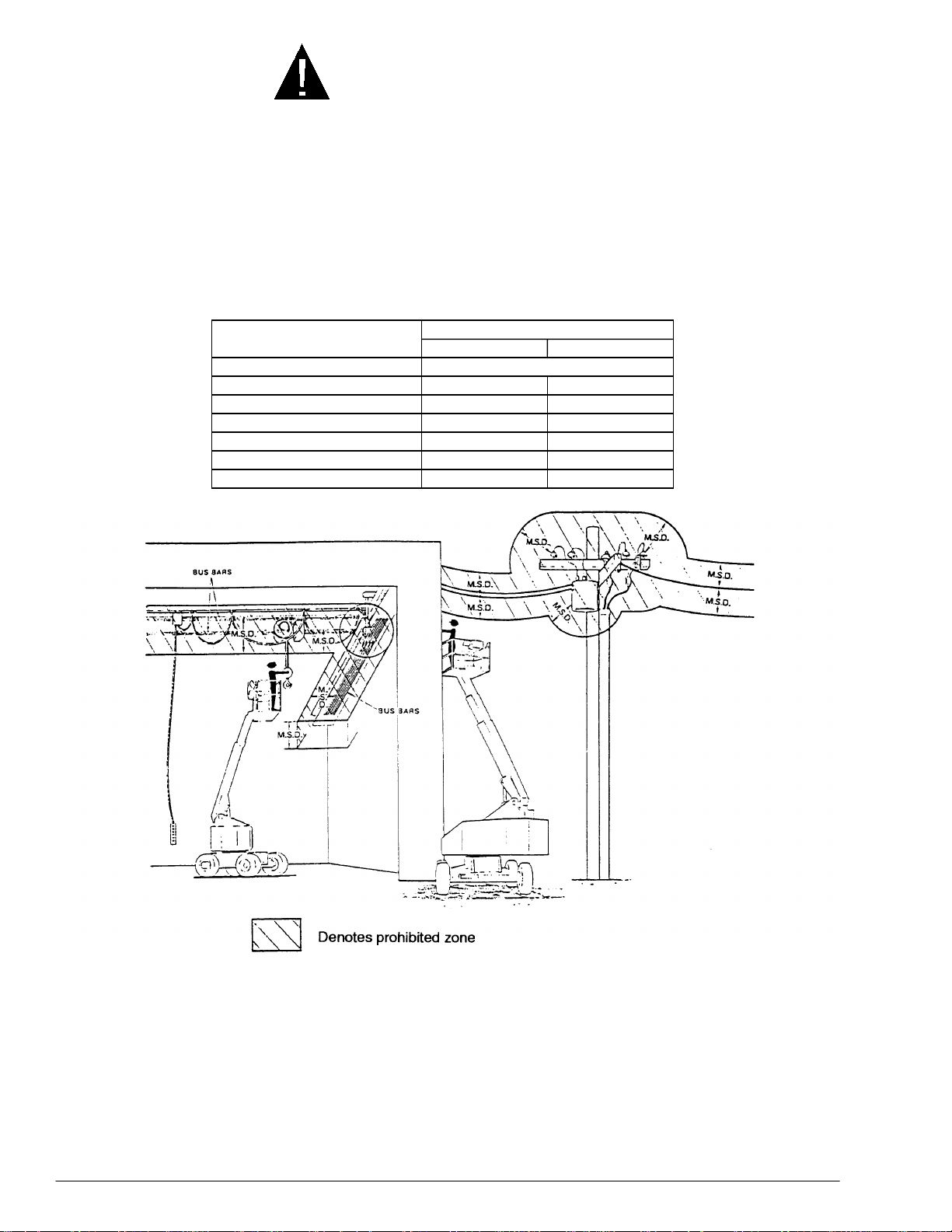
Table 1 - Minimum safe approach distance (M.S.A.D.)
to energized (exposed or insulated power lines
Voltage range
(phase to phase)
0 to 300V Avoid contact
Over 300V to 50KV 10 3.05
Over 50KV to 200KV 15 4.60
Over 200KV to 350KV 20 6.10
Over 350KV to 500KV 25 7.62
Over 500KV to 750KV 35 10.67
Over 750KV to 1000KV 45 13.72
Minimum safe approach distance
(Feet) (Meters)
Danger: - Do not allow machine personnel or conductive
materials inside prohibited zone.
- Maintain M.S.A.D. from all energized lines and parts
as well as those shown.
- Assume all electrical parts and wires are energized
unless known otherwise.
Caution: - Diagrams shown are only for purposes of illustrating
M.S.A.D. work positions, not all work positions.
Figure 3 - Minimum Safe Approach Distance (M.S.A.D.)
P/N 0191915
Page 3

DANGER
ELECTRICAL HAZARD
THE TB126J AERIAL WORK PLATFORM IS NOT
ELECTRICALLY INSULATED.
If the platform, booms, or any other conductive part of a TB126J contacts a highvoltage electrical conductor, the result can be
persons on or near the machine.
GO NO CLOSER THAN THE MINIMUM SAFE APPROACH
DISTANCES ON THE OPPOSITE PAGE.
Be sure to allow for sag and sway in the wires and the work platform.
If a TB126J comes in contact with a live electrical conductor, the entire machine
can be charged. If that happens, you should remain on the machine and not
contact any other structure or object within reach. That includes the ground,
adjacent buildings, poles, and any object not a part of the TB126J. Such contact
could make your body a conductor to the other object creating an electrical
shock hazard resulting in
or leave the TB126J until you are sure the electricity has been turned off.
SERIOUS INJURY
SERIOUS INJURY
DEATH
or
. Do not attempt to enter
or
DEATH
for
If a TB126J is in contact with a live conductor, the platform operator
others on the ground in the vicinity of the TB126J to
machine, since their bodies can also form a path for electricity to ground thus
creating an electrical shock hazard with possible
Do not attempt to operate the TB126J ground controls when the platform,
booms, or any other conducting part of a TB126J is in contact with electrical
wires or if there is an immediate danger of such contact.
Regard all conductors as energized.
Personnel working on or near a TB126J must be continuously aware of electrical
hazards, recognizing that
an electrical wire does occur.
SERIOUS INJURY
or
STAY AWAY
SERIOUS INJURY
DEATH
can result if contact with
MUST
from the
DEATH
or
warn
.
P/N 0191915
i
Page 4

TABLE OF CONTENTS
XX. CHAPTER TITLE
INTRODUCTION ....................................................iii
SIGNS .............................................................iii
QUALIFIED OPERATORS..............................iii
MAINTENANCE ..............................................iii
RESPONSIBILITIES OF PARTIES .................iv
ADDITIONAL INFORMATION.........................iv
1. SAFETY ............................................................. 1 - 1
SAFE OPERATION......................................... 1 - 1
Pre-start Inspection..................................... 1 - 1
Work Place Inspection and Practices ......... 1 - 1
Electrocution ............................................... 1 - 2
Tipover & Falling Hazards........................... 1 - 2
Crushing...................................................... 1 - 2
GENERAL SAFETY PRECAUTIONS.............. 1 - 2
Personnel Precautions................................ 1 - 2
Operator General Precautions .................... 1 - 2
Mounting & Dismounting Precautions......... 1 - 3
Starting and Stopping Precautions ............. 1 - 3
Operating Precautions ................................ 1 - 3
Operator Maintenance Precautions ............ 1 - 3
Fuel Handling Precautions.......................... 1 - 3
SAFETY DECALS & PLACARDS.................... 1 - 3
2. SAFETY DEVICES............................................. 2 - 1
TILT ALARM HORN, SIREN, & LIGHT ........... 2 - 1
EMERGENCY STOP SWITCHES................... 2 - 2
LANYARD ANCHOR POINTS......................... 2 - 2
GRAVITY GATE.............................................. 2 - 2
FOOT SWITCH ............................................... 2 - 3
GROUND OPERATION
EXTENDIBLE-AXLE INTERLOCKS................ 2 - 3
EMS LIGHTS & AUDIO ALARMS ................... 2 - 3
EMS TABLE .................................................... 2 - 5
OPERATOR HORN......................................... 2 - 5
DRIVING LIGHTS (option) .............................. 2 - 6
FLASHING LIGHTS (option) ........................... 2 - 6
PLATFORM WORK LIGHTS (option).............. 2 - 6
MOTION WARNING ALARM (option) ............. 2 - 6
GFCI OUTLET (option).................................... 2 - 6
GUARDRAILS ................................................ 2 - 6
3. SPECIFICATIONS ............................................. 3 - 1
GENERAL SPECIFICATIONS ........................ 3 - 1
PLATFORM SPECIFICATIONS ...................... 3 - 1
ENGINE DATA ................................................ 3 - 2
ENGINE OIL CHARTS .................................... 3 - 2
OVERALL DIMENSIONS ................................ 3 - 3
WORKING ENVELOPE .................................. 3 - 4
SERIAL-NUMBER LOCATIONS ..................... 3 - 5
CHASSIS NOMENCLATURE.......................... 3 - 5
TURNTABLE & BOOM NOMENCLATURE ......... 3 - 5
4. GAUGES............................................................ 4 - 1
FILTER MINDER............................................. 4 - 1
TEMPERATURE ............................................. 4 - 1
AMPS .............................................................. 4 - 1
HOURS
FUEL ............................................................... 4 - 2
HYDRAULIC OIL LEVEL................................. 4 - 2
HYDRAULIC OIL TEMPERATURE................. 4 - 2
HYDRAULIC OIL FILTER................................ 4 - 3
ENGINE OIL.................................................... 4 - 3
5. AUTOMATIC SHUT-OFFS
& CIRCUIT BREAKERS .................................... 5 - 1
AUTOMATIC SHUT-OFFS.............................. 5 - 1
CIRCUIT BREAKERS ..................................... 5 - 1
6. CONTROLS ....................................................... 6 - 1
GROUND-CONTROL BOX ............................. 6 - 2
PLATFORM-CONTROL BOX.......................... 6 - 4
CHASSIS......................................................... 6 - 6
TURNTABLE ................................................... 6 - 6
........................................................... 4 - 1
Engine Temperature ................................... 5 - 1
Engine Oil Pressure .................................... 5 - 1
Alternator Not Charging .............................. 5 - 1
SWITCH ................... 2 - 3
7. OPERATION...................................................... 7 - 1
CONTROL STATIONS.................................... 7 - 1
EMERGENCY STOPPING.............................. 7 - 1
STARTING FROM THE GROUND-
CONTROL BOX............................................ 7 - 1
Pre-start Conditions.................................... 7 - 1
Starting (from the ground)........................... 7 - 2
STARTING FROM THE PLATFORM-
CONTROL BOX............................................ 7 - 3
Pre-start Conditions.................................... 7 - 3
Starting (from the platform)......................... 7 - 4
MOVING THE PLATFORM............................. 7 - 5
MOVING THE PRO-126.................................. 7 - 8
STEERING...................................................... 7 - 8
125 V AC OUTLET AT THE PLATFORM........ 7 - 8
EXTEND & LOCK REAR AXLES.................... 7 - 9
RETRACT & LOCK REAR AXLES.................. 7 - 11
8. EMERGENCY OPERATION.............................. 8 - 1
EMERGENCY OPERATION FROM
THE PLATFORM-CONTROL BOX ............... 8 - 1
EMERGENCY OPERATION FROM
THE GROUND-CONTROL BOX................... 8 - 3
9. STOWING & TRANSPORTING......................... 9 - 1
STOWING....................................................... 9 - 1
TRANSPORTING............................................ 9 - 1
Trailering..................................................... 9 - 1
Securing to a Transport Vehicle ................. 9 - 3
Towing ........................................................ 9 - 4
10. DAILY INSPECTION & MAINTENANCE......... 10 - 1
DAILY INSPECTION AND
MAINTENANCE TABLE................................ 10 - 1
PLACARDS AND DECALS
INSPECTION CHART I................................. 10 - 10
PLACARDS AND DECALS
INSPECTION DRAWING I............................ 10 - 11
PLACARDS AND DECALS
INSPECTION CHART II................................ 10 - 12
PLACARDS AND DECALS
INSPECTION DRAWING II........................... 10 - 13
11. TROUBLESHOOTING..................................... 11 - 1
12. OPTIONS ......................................................... 12 - 1
PLATFORM WORK LIGHTS ..........................12 - 1
AIR LINE TO PLATFORM............................... 12 - 1
DRIVING LIGHTS ........................................... 12 - 1
COLD WEATHER START KIT........................ 12 - 1
Block Heaters .............................................12 - 1
Ether Injection............................................. 12 - 2
HYDRAULIC SYSTEM COLD
WEATHER WARM-UP KIT........................... 12 - 2
AC GENERATOR ...........................................12 - 2
MOTION WARNING ALARM ..........................12 - 2
TOW KIT ......................................................... 12 - 3
GFCI ...............................................................12 - 4
FLASHING LIGHTS ........................................ 12 - 4
SELF-CLOSING GATE ................................... 12 - 4
SPARK ARRESTOR ....................................... 12 - 4
13. FIRE FIGHTING & HAZARDOUS
CHEMICAL CONTAINMENT........................... 13 - 1
ANTI-FREEZE.................................................13 - 1
BATTERY, LEAD/ACID................................... 13 - 1
DIESEL FUEL ................................................. 13 - 1
FOAM IN TIRES..............................................13 - 1
GASOLINE...................................................... 13 - 2
HYDRAULIC OIL............................................. 13 - 2
LIQUEFIED PETROLEUM GAS .....................13 - 2
MOTOR OIL.................................................... 13 - 2
INDEX ....................................................................... I - 1
WARRANTY...................................(inside back cover)
ii
P/N 0191915
Page 5
INTRODUCTION
INTRODUCTION
The most important chapter in this manual is
“1. SAFETY.” Take time, now, to study it
closely. The information in that chapter might
save your life or prevent serious injury.
SIGNS
T
The following two conventions are used
throughout this manual.
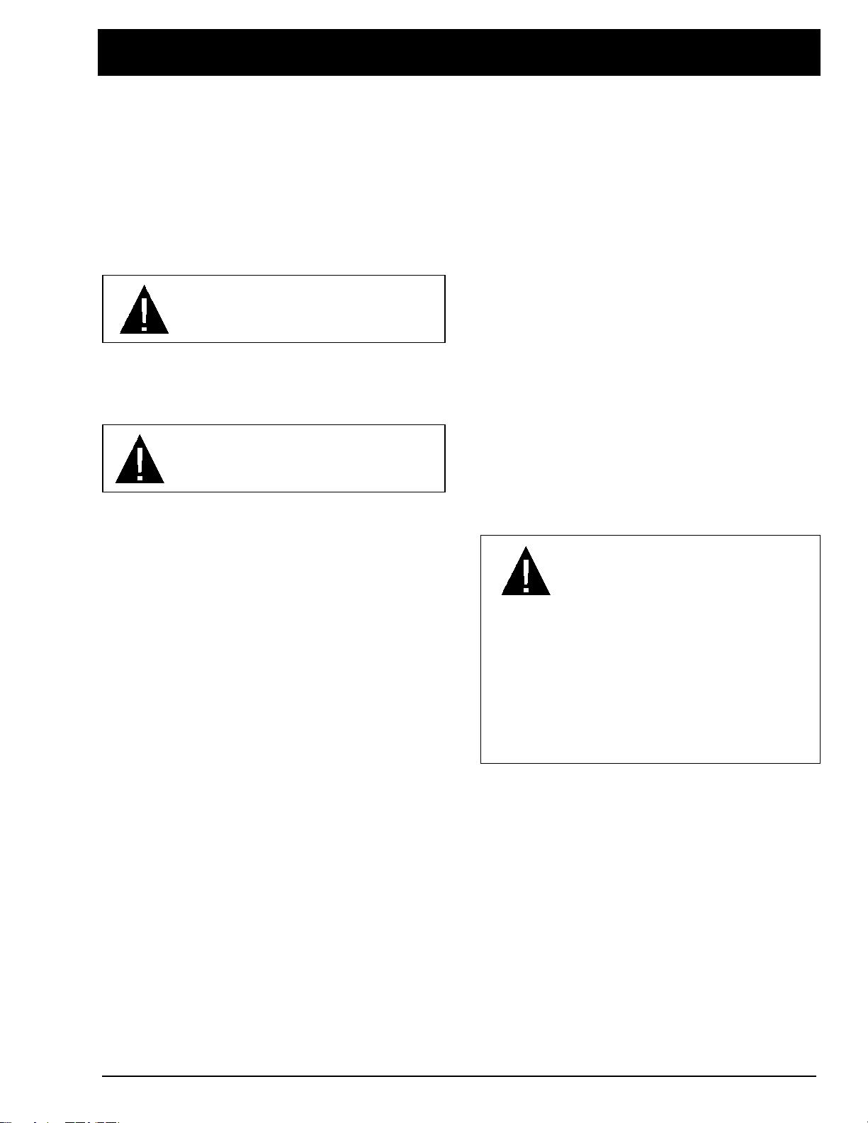
1. This sign
DANGER
means:
is involved
2. This sign
Attention! Become alert! Your safety
.
CAUTION
means one of two things: (1) an action, about to
be performed, is potentially hazardous and
might result in minor personal injury if not done
correctly, or (2) an action, about to be
performed, can damage the TB126J if not done
correctly.
QUALIFIED OPERATORS
T
The TB126J aerial platform has built-in safety
features and has been factory tested for
compliance with Snorkel specifications and
industry standards. However, any personnellifting device can be potentially dangerous in
the hands of untrained or careless operators.
The following rules will help ensure the
safety of personnel and help prevent
needless downtime because of damaged
equipment.
1. Only TRAINED and AUTHORIZED operators
shall be permitted to operate the equipment.
2. All manufacturer’s operating instructions and
safety rules and all employers’ safety rules and
all OSHA and other government safety rules
must be strictly adhered to.
3. Repairs and adjustments shall be made only
by QUALIFIED TRAINED maintenance
personnel.
4. No modification shall be made to the
equipment without prior written consent of the
Snorkel Engineering Department.
5. You must make a pre-start inspection of the
TB126J at the beginning of each shift. A
malfunctioning machine must not be used.
6. You must make an inspection of the work
place to locate possible hazards before
operating the TB126J.
DANGER
Misuse of this machine can result in DEATH
or SERIOUS INJURY.
Do not operate this equipment unless you
are TRAINED and AUTHORIZED and have
read and thoroughly understand all
information given in this Operator’s Manual
and on all DANGER and CAUTION signs on
the machine.
Training is essential and must be performed by
a QUALIFIED person. Become proficient in
knowledge and actual operation before using
the TB126J on the job. You must be trained
and authorized to perform any functions of the
TB126J. Operation of the TB126J must be
within the scope of the machine specifications.
Before operating the TB126J you must read
and understand the operating instructions in
this manual as well as the decals, warnings,
and instructions on the machine itself.
Before operating the TB126J you must be
AUTHORIZED by the person in charge to
do so.
P/N 0191915
MAINTENANCE
T
Every person who maintains, inspects, tests, or
repairs these machines, and every person
supervising any of these functions, must be
properly trained.
This Operator’s Manual provides a daily
inspection procedure that will help you keep
your TB126J in good operating condition. Do
not perform other maintenance unless you are
a TRAINED mechanic, QUALIFIED to work on
the TB126J. Call QUALIFIED maintenance
personnel if you find problems or malfunctions.
iii
Page 6

INTRODUCTION
Information contained in this manual concerns
only current TB126J’s, and the right is reserved
to make changes at any time without obligation.
RESPONSIBILITIES OF PARTIES
T
It is imperative that all owners and users of the
TB126J read, understand, and conform to all
applicable regulations. Ultimate compliance to
OSHA regulations is the responsibility of the
employer using the equipment.
ANSI Standard A92.5 identifies requirements of
all parties who might be involved with BoomSupported Elevating Work Platforms.
A reprint of the “Manual of Responsibilities for
Dealers, Owners, Users, Operators, Lessors
and Lessees of ANSI/SIA A92.5-1992 BoomSupported Elevating Work Platforms” is
available from Snorkel dealers or from the
factory upon request.
Copies are also available from:
Scaffold Industry Association
20335 Ventura Blvd. Suite 310
Woodland Hills, CA 91364-2471 USA
ADDITIONAL INFORMATION
T
For additional information, contact your local
dealer or write:
Snorkel International, Inc.
P.O. Box 1160
St. Joseph, MO 64502-1160 USA
816-364-0317
http://www.snorkelusa.com
iv
P/N 0191915
Page 7

1. SAFETY
1. SAFETY
SAFE OPERATION
T
The following safety information is vitally
important for safe operation of the TB126J.
Failure to follow these instructions can result in
personal injury or DEATH.
Pre-start Inspection
Prior to each shift, the TB126J shall be given a
visual inspection and function test. See the
“DAILY INSPECTION & MAINTENANCE”
chapter in this manual for a list of items to
inspect and test.
Do not operate the TB126J unless you are
trained and authorized, understand the operation
characteristics of the TB126J, and have
inspected and tested all functions to be sure they
are in proper working order. See the “DAILY
INSPECTION & MAINTENANCE” chapter.
Work Place Inspection and Practices
Do not use the TB126J as a ground for welding.
Ground to the work piece.
Before the TB126J is used, and during use,
check the area in which the TB126J is to be used
for possible hazards such as, but not limited to:
drop-offs or holes
•
bumps and floor obstructions
•
debris
•
overhead obstructions and high voltage
•
conductors
•
hazardous locations
•
inadequate surface and support to withstand
•
all load forces imposed by the aerial platform
•
in all operating configurations
•
wind and weather conditions
•
presence of unauthorized persons
•
other possible unsafe conditions
•
Before using the aerial platform in any hazardous
(classified) location, make certain it is approved
and of the type required by ANSI/NFPA 505 for
use in that particular location.
A recommended safety practice is to have
personnel that are trained in the operation of the
emergency controls working in the immediate
area of the TB126J to assist the platform
operator in the event of an emergency.
When moving the platform, check the clearance
around the TB126J to avoid contact with
structures or other hazards. Always look in the
direction of motion.
Keep ground personnel from under the platform
when the platform is raised.
Secure all accessories, containers, tools, and
other materials in the platform to prevent them
from accidentally falling or being kicked off the
platform.
Do not engage in any form of “horseplay” or
“stunt driving” while operating the TB126J.
Do not permit riders on the machine anyplace
other than on the platform.
Remove all loose objects stored in or on the
machine, particularly in the platform. Remove all
objects which do not belong in or on the
machine.
When other moving equipment is in the area,
take special precautions to comply with local
regulations regarding warnings.
Never steady the platform by positioning it
against another platform.
Do not operate a TB126J that is not functioning
properly, or has been damaged, until the
machine has been repaired by a qualified
maintenance person.
Do not operate a TB126J that does not have all
its decals and placards attached and legible.
Drive the machine with care and at speeds
compatible with conditions. Use extra caution
when driving over rough ground, on slopes, and
when turning.
Know and understand the job site traffic-flow
patterns and obey the flagmen, road signs, and
signals.
P/N 0191915
Watch for bystanders and never allow anyone to
be under, or to reach through, the machine and
its equipment while operating.
Use the recommended transport device when
loading the machine.
1 - 1
Page 8

1. SAFETY
Electrocution
The TB126J is an all-metal boom, NONINSULATED, aerial work-platform. Do not
operate it near ELECTRICAL conductors.
Regard all conductors as being energized.
Do not operate outside during a thunderstorm.
Tipover & Falling Hazards
Do not operate a TB126J from a position on
trucks, trailers, railway cars, floating vessels,
scaffolds, or similar equipment unless the
application is approved in writing by Snorkel.
If the platform or elevating assembly becomes
caught, snagged, or otherwise prevented from
normal motion by an adjacent structure or other
obstacles such that control reversal does not free
the platform, remove all personnel from the
platform before attempts are made to free the
platform using ground controls.
It is best not to transfer from the platform to
another structure or from the structure to the
platform, unless that is the safest way to do the
job. Judge each situation separately taking the
work environment into account. If it is necessary
to transfer from the platform to another structure
the following guidelines apply:
Where possible, place the work platform
•
over a roof or walking structure to do the
transfer.
Transfer your anchorage from one
•
structure to another before you step
across.
Remember that you might be transferring
•
to a structure where
is required.
Use the platform entrance, do not climb
•
over the guard rails.
All platform occupants MUST wear a fall restraint
device connected to a lanyard anchor point.
Do not exceed the unrestricted platform capacity
shown on the platform.
Do not raise the boom if the TB126J is on soft
ground. Operate the boom only on a firm surface
capable of withstanding all load forces imposed
by the aerial platform in all operating conditions.
personal fall arrest
Care shall be taken to prevent rope, electric
cords, and hoses, etc., from becoming entangled
in the aerial platform.
Raise the platform only when the TB126J is on
level ground.
Maintain a firm footing on the platform floor.
Climbing on the guard rails is prohibited.
Do not use ladders, planks, or other devices to
extend or increase your work position from the
platform.
Do not jerk the controls. Move the controls slowly
and deliberately to avoid jerky and erratic
operation. Always stop the controls in the neutral,
off, position before going in the opposite
direction.
Do not use the boom for any purpose other than
to position personnel, their tools, and materials.
Do not use the TB126J as a crane, hoist, or jack.
Do not operate the TB126J in winds, or wind
gusts, of 28 mph (45 km/hr) or more.
Do not add anything to the TB126J that will
increase the wind loading (billboards, banners,
flags, etc).
Crushing
Always look in the direction of travel. Avoid
overhead obstructions.
Never cover the floor grating or otherwise
obstruct your view below.
Make sure the area below the platform is free of
personnel before lowering.
T
GENERAL SAFETY PRECAUTIONS
Personnel Precautions
If you encounter any suspected malfunction of
the aerial platform, or any hazard or potentially
unsafe condition relating to capacity, intended
use, or safe operation, cease operation and seek
assistance from management.
Operator General Precautions
Make sure that all protective guards, cowlings,
and doors are in place and secure.
Do not carry loads from any point outside of the
platform.
1 - 2
Be sure the guardrail system, including the gate,
is in place and secure.
P/N 0191915
Page 9

Mounting & Dismounting Precautions
Fuel Handling Precautions
1. SAFETY
Use three points of support when getting on or
off the platform (two hands and one foot or a
similar set of points). Keep the platform clean.
Do not jump off the machine.
Do not dismount while the machine is in motion.
Starting and Stopping Precautions
Do not start until all personnel are clearly away
from the machine.
Before leaving the operator’s station, place the
machine in the stowed position.
When leaving the machine parked or
unattended, remove the starter key from the
MASTER KEY SWITCH
switch to OFF, then lock the
Operating Precautions
Do not modify the TB126J in any way.
When parts or components are replaced, they
shall be identical or equivalent to original Snorkel
parts or components.
Do not override any of the safety features of the
TB126J.
Limit travel speeds according to conditions. Take
into account: grade, surface, congestion,
visibility, side slope, location of personnel, and
other hazards.
Operator Maintenance Precautions
Do not use your hand to search for hydraulic oil
leaks. High pressure hydraulic oil can easily cut
and penetrate your skin — a very serious injury
that requires immediate attention by a medical
specialist trained in that type of injury. Use a
piece of cardboard or wood to search for
hydraulic oil leaks.
Do not attempt repairs unless you are trained.
Refer to manuals and experienced repair
personnel for help.
, set the
BATTERY
BATTERY
switch.
Do not smoke or permit open flames while
fueling or near fueling operations.
Never remove the fuel cap or refuel a gasoline
engine while the engine is running or hot. Never
allow fuel to spill on hot machine components.
Maintain control of the fuel filler nozzle when
filling the tank.
Do not fill the fuel tank to capacity. Allow room
for expansion.
Clean up spilled fuel immediately.
Tighten the fuel tank cap securely. If the fuel cap
is lost, replace it with an approved cap from
Snorkel. Use of a non-approved cap without
proper venting may result in pressurization of the
tank.
Never use fuel for cleaning purposes.
For diesel engines, use the correct fuel grade for
the operating season.
T
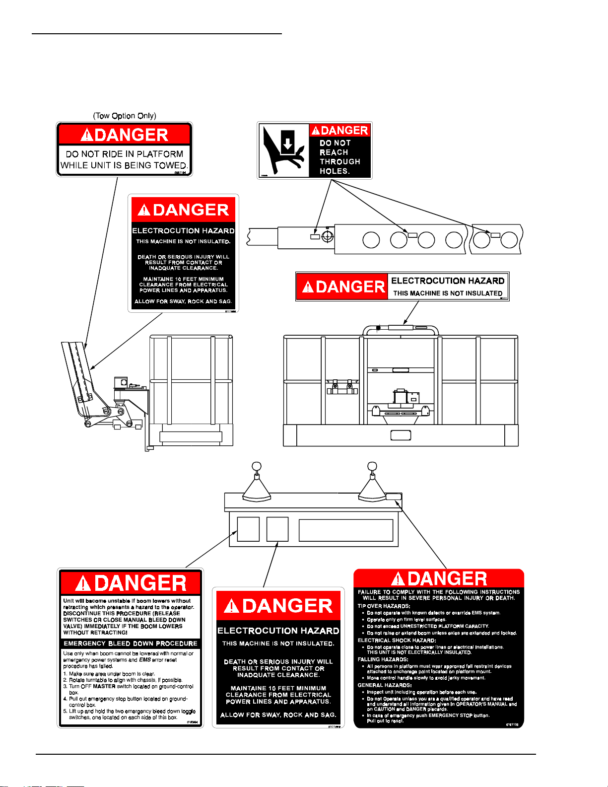
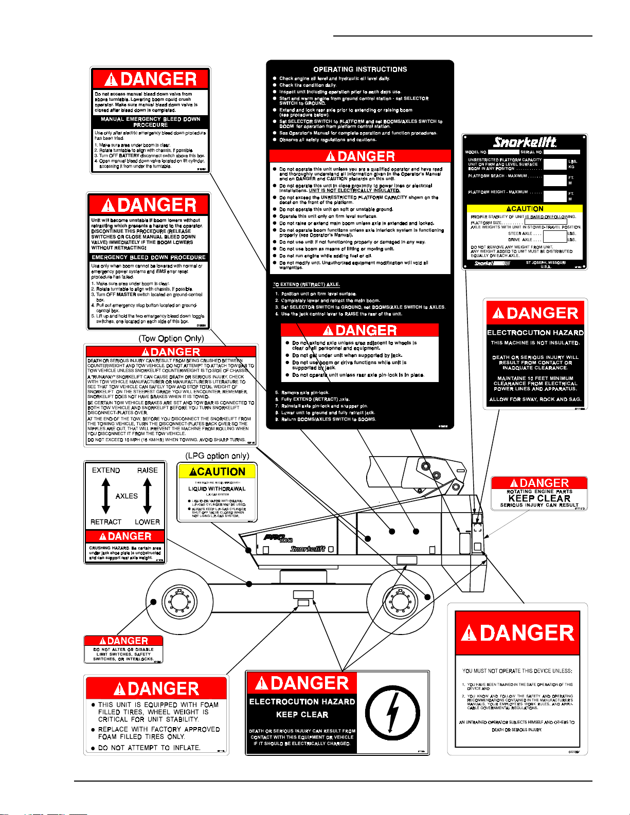
SAFETY DECALS & PLACARDS
There are several safety decals and placards on
the TB126J. Their locations and descriptions are
shown in this section. Take time to study them.
Be sure that all the safety decals and placards
on the TB126J are legible. Clean or replace them
if you cannot read the words or see the pictures.
Clean with soap & water and a soft cloth. Do not
use solvents.
You must replace a decal or placard if it is
damaged, missing, or cannot be read. If it is on a
part that is replaced, make sure a new decal or
placard is installed on the replaced part. See
your Snorkel dealer for new decals and placards.
Refer to PLACARDS AND DECALS
INSPECTION CHARTs and DRAWINGs in the
“DAILY INSPECTION AND MAINTENANCE”
chapter for part numbers, location, and required
quantities of all placards and decals.
Charge batteries in a well-ventilated area free of
flame, sparks, or other hazards that might cause
fire or explosion.
Use extreme caution when removing radiator
caps. Park the machine and let it cool down
before opening a pressurized compartment.
P/N 0191915
1 - 3
Page 10
1. SAFETY
Refer to PLACARDS AND DECALS INSPECTION CHARTS and DRAWINGS in the “DAILY
INSPECTION AND MAINTENANCE” chapter for part numbers, locations, and required
quantities of all placards and decals.
1 - 4
P/N 0191915
Page 11
1. SAFETY
P/N 0191915
1 - 5 (1 - 6 blank)
1 - 5
Page 12
For emergency operation controls and
procedures, see the “EMERGENCY
OPERATION” chapter in this manual.
The devices listed in this chapter are safety
devices. They are on a TB126J to increase
safety in the work place for both the operator and
other people near a TB126J. Do not by-pass,
disable, modify, or ignore any of these devices.
Check them carefully at the start of each work
shift to see that they are in working order (see
“DAILY INSPECTION & MAINTENANCE”
chapter). If any is found to be defective, remove
the TB126J from service immediately until a
qualified service technician can make repairs.
T
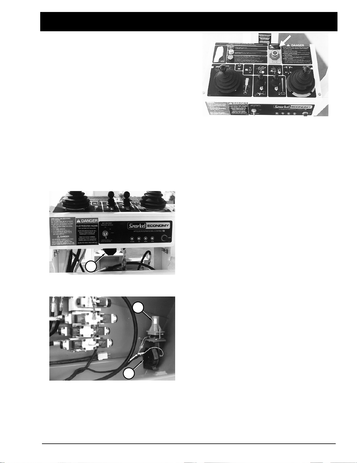
TILT-ALARM HORN, SIREN, & LIGHT
There is one tilt-alarm siren, one tilt-alarm horn,
and one tilt-alarm warning light on a TB126J.
2. SAFETY DEVICES
The tilt-alarm warning light is on the platformcontrol box.
The siren will emit a two-toned sound (high-lowhigh-low...) if the TB126J is tilted more than 3.5
(7 inch rise in 10 foot run / 18 cm rise in 3 m run)
and the booms are above horizontal or extended
more than 7 feet (2 m). The warning light will
come on and the horn will emit a continuous
sound at the same time the siren sounds.
2. SAFETY DEVICES
°
1
The siren (1) is located under the platformcontrol box.
3
NOTE: The platform siren will not sound if the
TB126J is being controlled from the groundcontrol box.
After the siren and/or horn begins to sound, if the
tilt continues to increase, the TB126J can tip
over. When you are in control of a TB126J and
you hear either of these two warning sounds, or
see the warning light come on, you should
immediately:
1. Stop using the
on the platform-control box.
2. Completely retract and completely lower the
booms.
3. Use the platform-control box
controller to move the TB126J to a level surface
or more firm ground before extending or raising
the booms again.
DRIVE/STEER
controller stick
DRIVE/STEER
2
The horn (2) is located in the turntable under the
tilt alarm sensor (3).
P/N 0191915
2 - 1
Page 13
2. SAFETY DEVICES
T
EMERGENCY STOP SWITCHES
T
LANYARD ANCHOR POINTS
OSHA regulations require all personnel on the
platform to attach the lanyard of their fall restraint
to a secure anchor point to prevent falls. The
anchorage point is the anchor to which you
should attach your fall restraint lanyard.
At the ground-control box:
EMERGENCY STOP
under any conditions, and the entire machine
stops, the engine turns off, and nothing moves.
This switch must be pulled up (out) for anything
on the TB126J to work.
At the platform-control box:
red
EMERGENCY STOP
entire machine stops, the engine turns off, and
nothing moves. This switch must be pulled to its
up (out) position to control the TB126J from the
platform.
NOTE: The ground-control box is designed to
override the platform-control box. If the
platform-control box
button is down (off) the ground-control box
can still be used to start and operate the
TB126J.
button in, at any time,
Press the red
Press the large
button down and the
EMERGENCY STOP
T
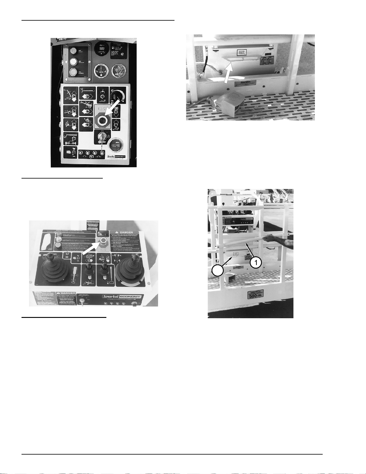
GRAVITY GATE
2
The gravity gate (1) is the place in the platform
guardrail system where you should enter and
leave the platform. Raise the gate and step
under it onto the platform. Once you have
entered the platform and attached your fall
restraint lanyard to the anchorage point (2),
check to see that the gravity gate (1) has fallen
back into place.
2 - 2
P/N 0191915
Page 14
2. SAFETY DEVICES
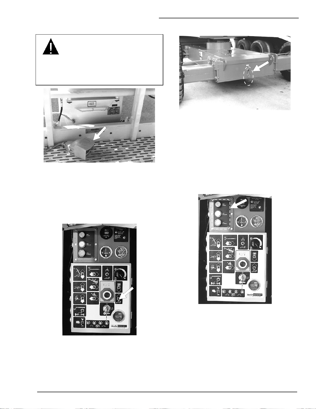
T
FOOT SWITCH
DANGER
Serious injury can result from sudden stops.
To avoid sudden stops, do not remove your
foot from the foot switch while the TB126J is
in motion.
The foot switch prevents the platform from
moving if something accidentally pushes one of
the platform controls on the platform-control box.
(It is a second action that must be performed, at
the same time as another, to make the platform
move.)
T
EXTENDIBLE-AXLE INTERLOCKS
The left and right rear axles of a TB126J must be
extended and locked for safe-working machine
stability. The booms cannot be raised or
extended unless the axles are completely
extended and locked into place. Instructions for
extending and locking the axles are given in the
“OPERATION” chapter.
T
EMS LIGHTS & AUDIO ALARMS
There are six envelope management system
(EMS) lights on a TB126J.
T
GROUND OPERATION SWITCH
The
GROUND OPERATION
platform from moving if something accidentally
pushes one of the platform-moving switches at
the ground-control box. (It is a second action that
must be performed, at the same time as another,
to make the platform move.)
switch prevents the
Three are on the instrument panel.
P/N 0191915
2 - 3
Page 15

2. SAFETY DEVICES
A second identical set of three is on the platformcontrol box.
2
1
In addition to EMS lights there are EMS audio
alarms.
3
The
EMS ENVELOPE
information about where the platform is located
relative to the platform’s safe working envelope.
(See the “SPECIFICATIONS” chapter for the
TB126J safe working envelope.) The
STATUS
the operator whether or not the envelope
management system is operating correctly .
(2) and
NOTE: EMS lights on the platform-control box
have the same names as those on the
instrument panel even though they are not
labeled on the platform-control box.
lights (1) give the operator
EMS
EMS WARNING
lights (3) tell
Two are above the instrument panel.
Two are on the bottom of the platform-control
box. The audio alarms emit various sounds to
alert the operator to unsafe conditions. The audio
alarms and EMS lights work together to give
valuable safety information. The table below
summarizes that information.
NOTE: When a TB126J engine first starts, the
EMS self-test will briefly sound all EMS audio
alarms and briefly turn all six EMS lights on to
check that they work. After the brief EMS selftest, conditions in the table below prevail.
2 - 4
P/N 0191915
Page 16
2. SAFETY DEVICES
EMS TABLE
LIGHT CONDITION AUDIO ALARM
GREEN
EMS
STATUS
WHITE
EMS
ENVELOPE
RED
ON
: Machine is ready for normal operation.
FLASHING
technician.
OFF
: Platform is well inside the safe working envelope.
FLASHING
safe working envelope.
ON
: Platform is outside the limits of the safe working
envelope.
ON
: EMS error detected. Press the red
light completely in and release it
WARNING
procedures described in the “EMERGENCY
OPERATION” chapter to retrieve the platform.
: Calibration error. Notify qualified service
DO NOT USE MACHINE
: Platform is less than 3 feet (1 m) inside the
light stays on, use the emergency
.
slowly
EMS WARNING
. If the red
None.
None.
None.
None.
None.
Continuous tone.
EMS
EMS
WARNING
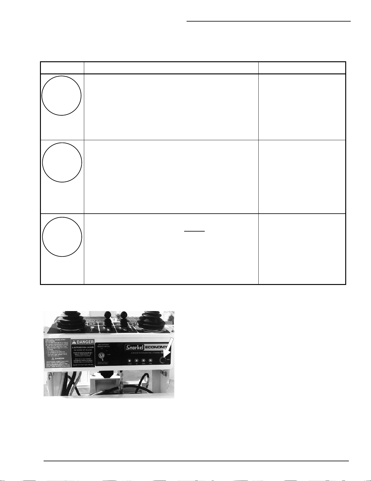
OPERATOR HORN
T
The operator
of the platform-control box. It is used primarily
to get the attention of people on the ground
when you are working aloft.
FLASHING
working envelope. Move boom into safe working
envelope.
HORN
: Platform is outside the limits of the safe
button is on the right side
Beeping
The horn itself is located below the tilt alarm
sensor, it is the same horn used to sound the
tilt alarm. For the horn to work the
switch must be ON and the following switches,
on the ground-control box, must be set as
indicated:
SELECTOR SWITCH
EMERGENCY STOP
MASTER KEY SWITCH
..........PLATFORM
... ...........pulled out
....................ON
BATTERY
P/N 0191915
2 - 5
Page 17
2. SAFETY DEVICES
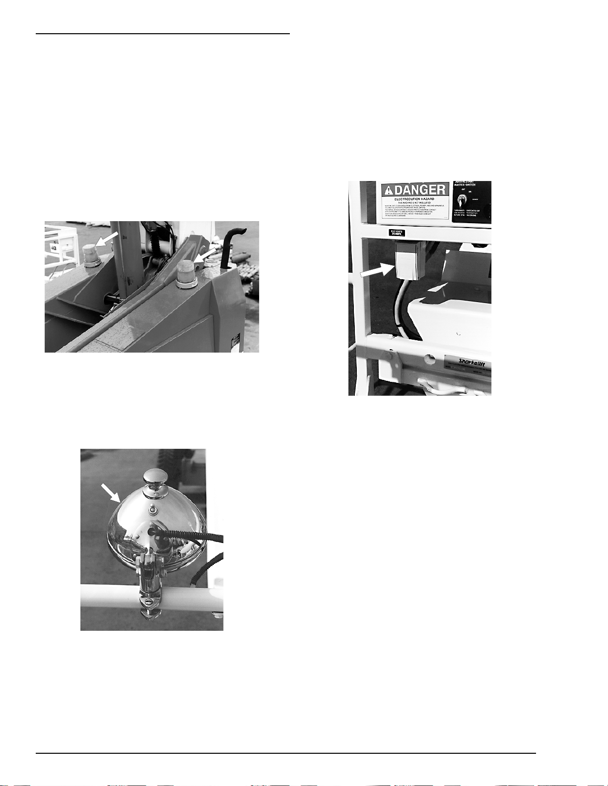
DRIVING LIGHTS (option)
T
MOTION WARNING ALARM
T
(option)
Two 30 watt headlights are located on top of
the front cowling, two 25 watt blinking taillights
are on the sides of the rear cowlings. Driving
lights help improve your visibility and help
others see you when you are driving on dimly lit
construction sites. Driving lights are not for
driving on public thoroughfares.
For more information about driving lights see
the “OPTIONS” chapter.
FLASHING LIGHTS
T
The flashing lights alert people that the TB126J
is present. The lights flash at about one flash
per second any time the engine is running.
There is no ON/OFF switch for the flashing
lights.
PLATFORM WORK LIGHTS
T
(option)
(option)
The motion warning alarm emits a loud beeping
sound at ground level anytime the
DRIVE/STEER
REVERSE. This alarm alerts people on the
ground that the TB126J is traveling along the
ground.
GFCI OUTLET
T
The GFCI (ground fault circuit interrupt) is the
electrical outlet located under the platformcontrol box. The GFCI protects against short
circuits to ground. When there is a short to
ground the GFCI shuts off power at the
electrical outlet.
controller is in FORWARD or
(option)
The platform work lights are located on top the
platform guard rail. Use the lights to improve
visibility when you are working aloft in dimly lit
areas. Do not use the platform work lights to
drive on public thoroughfares.
For more information about platform work lights
see the “OPTIONS” chapter.
2 - 6
For more information about the GFCI see the
“OPTIONS” chapter.
GUARDRAILS
T
The guardrails help protect you from falling off
the platform. Be sure the guardrails are
properly installed and that the gate is in place.
P/N 0191915
Page 18

3. SPECIFICATIONS
3. SPECIFICATIONS
The TB126J is a boom-supported elevating
work-platform built to conform to the following
standards:
OSHA Paragraph 1910.67 Title 29,
C.F.R.Vehicle-Mounted Elevating and Rotating
Work Platforms - Labor.
OSHA Paragraph 1926.556 Title 29, C.F.R.,
Aerial Lifts - Construction.
ANSI Standard A92.5, Boom-Supported
Elevating Work Platforms.
GENERAL SPECIFICATIONS
T
Working height (nominal) .....132 ft - 0 in (40.2 m)
Platform height (maximum) ..126 ft - 0 in (38.4 m)
Platform reach (maximum).....63 ft - 0 in (19.2 m)
Length
(booms down and retracted)..42 ft - 9 in (13.0 m)
Width:
axles retracted.........................8 ft - 6 in (2.6 m)
axles extended.....................12 ft - 10 in (3.9 m)
Height (booms down)...............10 ft - 4 in (3.1 m)
Wheelbase...............................12 ft - 0 in (3.7 m)
Ground clearance ........................... 13 in (33 cm)
Weight (approximate)....... 41,800 lbs (19,000 kg)
Wheel load, max. single ...... 21,170 lbs (9603 kg)
Ground pressure (max.) ............. 91 psi (628 kPa)
Travel speeds (max.) (See “CONTROLS”
chapter for explanation of settings for different
speeds.):
booms down and retracted
high speed, low torque .....3.0 mph (4.8 km/hr)
mid speed, mid torque......1.5 mph (2.4 km/hr)
high torque, low speed ...0.75 mph (1.2 km/hr)
booms up and/or extended
to mid elevation ..............0.75 mph (1.2 km/hr)
above mid elevation................................creep
Gradeability...................................................25%
Turning radius
outside................................ 33 ft - 0 in (10.0 m )
inside, axles retracted............ 21 ft - 2 in (6.5 m)
inside, axles extended ...........19 ft - 0 in (5.8 m)
Tires (foam filled) . 18 x 22 in (46 X 56 cm), 18 ply
Electrical system...12 V dc (neg. chassis ground)
Environmental operating ranges:
ambient air temperature ..............0°F to +110°F
(-18°C to +43°C)
wind speed
(maximum gust or steady) .... 28 mph (45 km/hr)
Fuel tank capacity:
std. gasoline/diesel........ 40 gal USA (151 liters)
optional LPG..................... 43.5 lbs USA (20 kg)
Hydraulic oil:
tank capacity ................. 60 gal USA (227 liters)
maximum temperature (at tank)... 200°F (93°C)
system capacity............. 90 gal USA (341 liters)
maximum pressure........ 2,800 psi (19,320 kPa)
Hydraulic oil recommended:
above 10°F (-13°C) Mobil DTE 13M (ISO VG32)
below 10°F (-13°C) Mobil DTE 11M (ISO VG15)
Boom elevation ...................+75°/-1° to horizontal
Boom movement times (complete range of
movement):
Jib Boom
UP..........................................40 - 45 seconds
DOWN ...................................16 - 20 seconds
Turntable Swing
360° CW or CCW,
boom retracted.................110 - 120 seconds
boom extended ................320 - 330 seconds
Platform Rotation
180° CW or CCW,.................. 16 - 20 seconds
Main Boom Elevation
UP (boom retracted).............90 - 120 seconds
UP (boom extended) ........... 150 -180 seconds
DOWN (boom retracted) .....90 - 120 seconds
DOWN (boom extended).....150 -180 seconds
Boom Extension
OUT .......................................65 - 75 seconds
IN ........................................... 35 - 45 seconds
PLATFORM SPECIFICATIONS
T
Unrestricted rated work load (total weight of personnel,
SIZE
PLATFORM
standard self-stowing
aluminum 30 x 92 (76 x 234) 500 lbs (227 kg) = 2 people + 147 lbs (67 kg)
optional steel 30 x 60 (76 x 152) 600 lbs (273 kg) = 3 people + 70 lbs (32 kg)
P/N 0191915
inches (cm)
tools, and materials that the platform is designed to
carry above its floor -- same as UNRESTRICTED
PLATFORM CAPACITY)
3 - 1
Page 19
3. SPECIFICATIONS
ENGINE DATA
T
ENGINE MAKE CONTINENTAL CONTINENTAL CUMMINS
MODEL TM27 4B3.9
FUEL gasoline LPG diesel
FUEL GRADE unleaded
85 octane
(motor method)
CYLINDERS 4
COOLANT 50% water + 50% ethylene glycol
POWER 71.5 hp @ 3000 rpm
(53.3 kW)
OPERATING TEMPERATURE
OIL SUMP CAPACITY 6 qt USA
OIL FILTER CAPACITY 1 qt USA
OIL GRADE API: SE, SF, SE/CD, SF/CD API: CE/SF, CD/SF
OIL WEIGHT see chart below see chart below
RUNNING TIME One full tank of gasoline or diesel will last an entire eight hour shift,
180°F - 202°F
(81°C - 94°C)
(5.7 liters)
(0.95 liters)
under normal working conditions. It normally takes between one and
two tanks of LPG per eight hour shift.
HD5
Gas Processors
Association Standard
2140. Category:
special duty
propane.
64.4 hp @ 3000 rpm
(48.0 kW)
ASTM No. 2 D
Cetane # > 40
(For operating temp.
below 32°F / 0°C use
“winterized” No. 2 D.)
76 hp @ 2500 rpm
(56.7 kW)
141°F - 211°F
(60°C - 100°C)
10 qt USA
(9.5 liters)
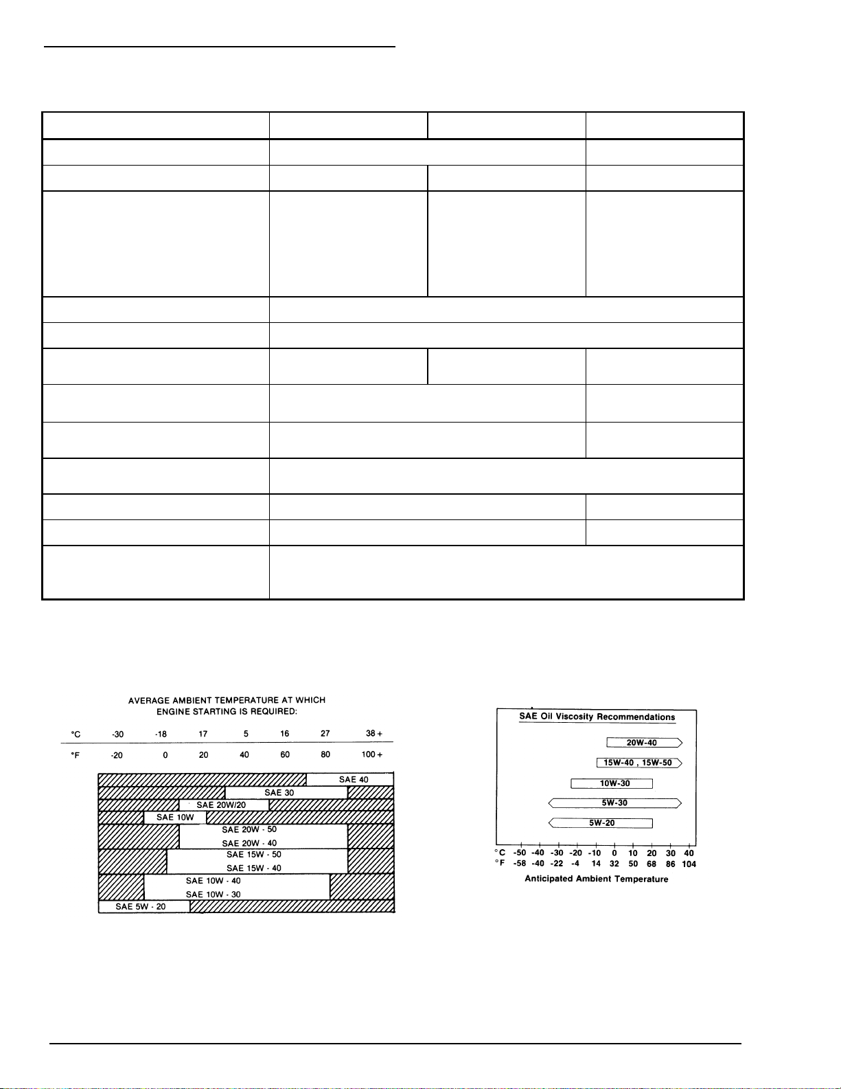
ENGINE OIL CHARTS
T
CONTINENTAL ENGINE CUMMINS ENGINE
3 - 2
P/N 0191915
Page 20
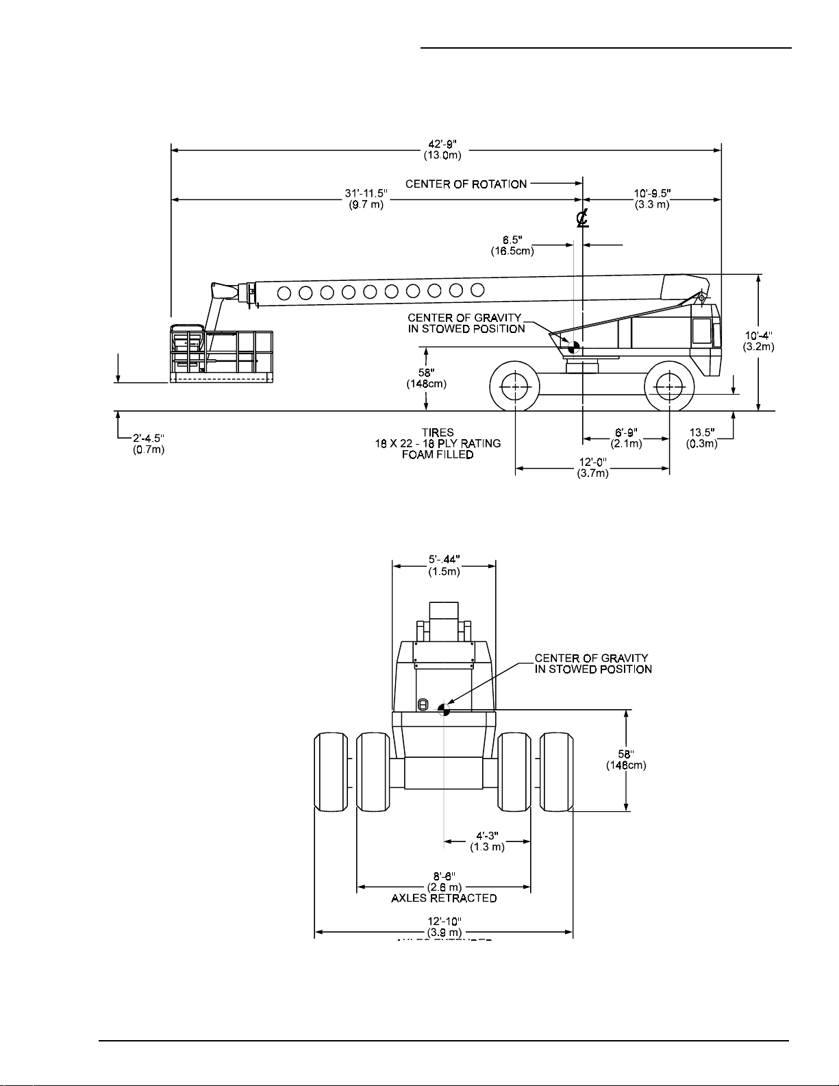
OVERALL DIMENSIONS
T
3. SPECIFICATIONS
P/N 0191915
3 - 3
Page 21
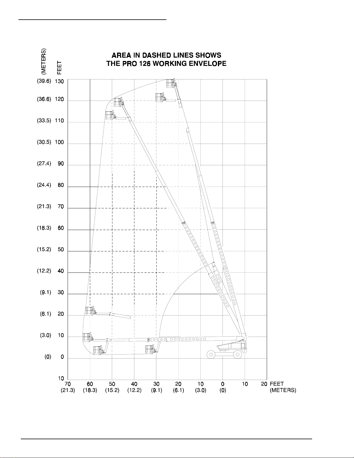
3. SPECIFICATIONS
WORKING ENVELOPE
T
3 - 4
P/N 0191915
Page 22
3. SPECIFICATIONS
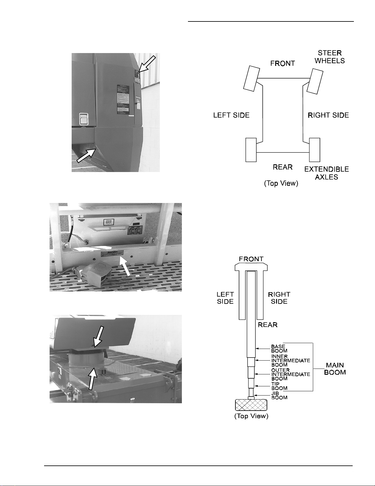
SERIAL-NUMBER LOCATIONS
T
Serial Numbers are located in five places.
1. Above the ground-control box on a placard.
(The last four digits are month and year
shipped.)
2. On the back-right of the counterweight.
CHASSIS NOMENCLATURE
T
3. On the platform toe-board, below the lanyard
anchor points, on a placard. (Last four digits
are mo. and yr. shipped.)
TURNTABLE & BOOM
T
NOMENCLATURE
NOTE: If the turntable is rotated 180° its
FRONT is above the REAR of the chassis.
4. Below the drain hole in the turntable.
5. At the weld behind the rotation-bearing
turret.
P/N 0191915
3 - 5 (3 - 6 blank)
3 - 5
Page 23
4. GAUGES
4. GAUGES
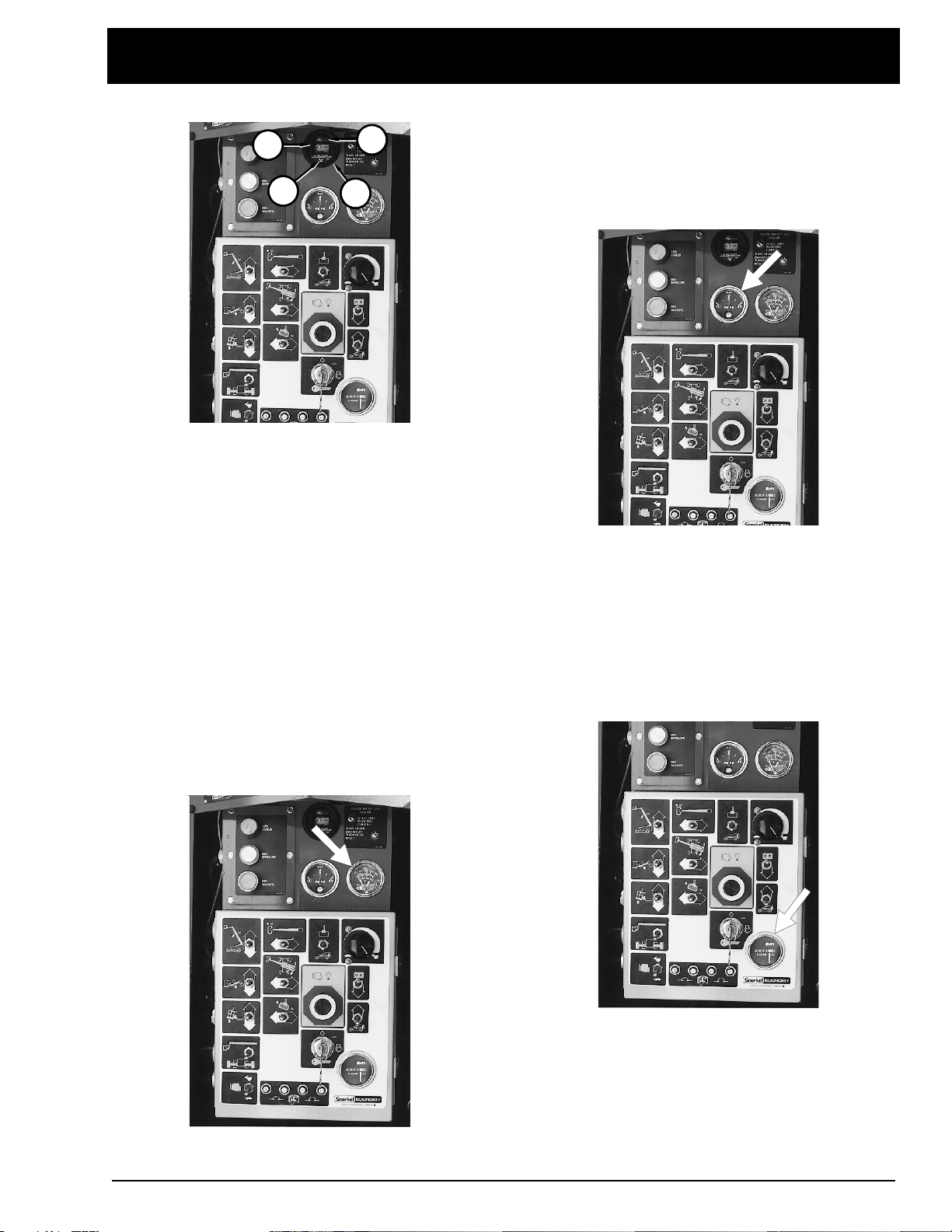
T
FILTER MINDER
2
4
The air filter gauge (1)
located just above the ground-control box. The
gauge measures the vacuum (air pressure)
between the intake manifold and the air filter. As
the filter clogs, the vacuum increases (pressure
drops). As the vacuum increases, the yellow
indicator (2) raises toward the red area (3) of the
sight glass. When the yellow indicator reaches
the red, it’s time to change the air filter.
The indicator (2) stays at its highest setting, it
does not go to the bottom of the sight glass
when the engine is turned off. After the filter is
changed, press the small
reset the indicator disk to the bottom of the sight
glass.
(FILTER MINDER)
RESET
3
1
is
button (4) to
temperature of the water-antifreeze mixture in
the engine block. The typical operatingtemperature range for a Continental engine is
180°F to 202°F (81°C to 94°C); for a Cummins
engine, 141°F to 211°F (60°C - 100°C).
T
AMPS
The
AMPS
from the alternator to the batteries. When the
engine is running, the needle in the
should not be to the left of “0.” Under normal
operating conditions, after the engine has been
running for a few minutes, this gauge should
read “0.”
T
HOURS
gauge shows the electric current
AMPS
gauge
T
TEMPERATURE
The
TEMPERATURE
above the ground-control box. It shows the
P/N 0191915
gauge is located just
The
HOURS
It accumulates time when:
BATTERY
SELECTOR SWITCH
MASTER KEY SWITCH
It also accumulates time when:
BATTERY
gauge is basically an electric clock.
........................ON
.......GROUND
...ON.
........................ON
4 - 1
Page 24
4. GAUGES
SELECTOR SWITCH
ANTI-RESTART
MASTER SWITCH
The
HOURS
when it is time to perform the periodic
maintenance listed in the Maintenance Manual.
T
FUEL
gauge cannot be reset. Use it to tell
...... PLATFORM
......... ON.
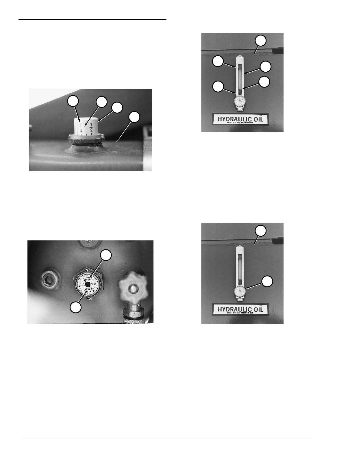
T
HYDRAULIC OIL LEVEL
4
5
2
1
3
4
3
1
2
The fuel gauge (1) is located on top of the
gasoline or diesel fuel tank (2). Read it at the line
(3) in the clear plastic window (4). It reads in
fractions-of-a-full-tank. The tank shown is a little
more than 1/4 full.
NOTE: Do not run a diesel fuel tank dry. Air in
the fuel line makes a diesel engine hard to
start.
1
The hydraulic-oil level gauge (1) is on the side of
the hydraulic oil tank (2). It shows the actual level
of oil inside the tank. Read it only when the
booms are completely down and completely
retracted. Otherwise, the lift and/or extend
cylinders become large reservoirs for hydraulic
oil and the oil level in the tank will be low. The oil
level (3) should be between the
and
T
HYDRAULIC OIL TEMPERATURE
LOW
mark (5).
HIGH
mark (4)
2
2
(OPTION - LPG) LPG tanks have two fuel
gauges (1) (2) on top. One measures correctly
when the tank is standing on end (
the other measures correctly when the tank is
laying down (
fractions-of- a-full-tank. TB126J tanks are
mounted horizontally. Therefore, you should read
the
HORIZONTAL
HORIZONTAL
scale (2).
). Both read in
VERTICAL
)
4 - 2
1
The hydraulic-oil temperature gauge (1) is
located at the bottom of the hydraulic-oil level
gauge. It measures the temperature of the oil in
the tank (2). The temperature should not exceed
200°F (93°C). If it does, reduce your driving
speed or stop the TB126J to let the hydraulic oil
cool.
P/N 0191915
Page 25
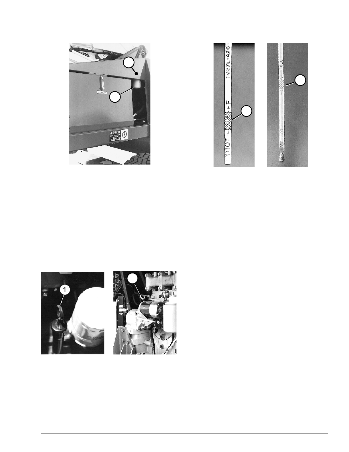
T
HYDRAULIC OIL FILTER
1
2
The hydraulic-oil filter gauge (1) is located above
the hydraulic-oil filter (2). The gauge measures
pressure into the filter. As the filter clogs, the
pressure goes up.
4. GAUGES
CONTINENTAL CUMMINS
4
3
Engine oil level should always be in the crosshatched area (3) (4) of the dipstick — never
above or below it. Check the oil level after the
engine has been turned off a few minutes so that
oil can run down out of the engine into the sump.
The hydraulic-oil filter gauge should only be read
by qualified trained maintenance personnel. An
accurate reading requires very special conditions
and should not be attempted by operators.
T
ENGINE OIL
CONTINENTAL CUMMINS
2
Engine oil level is measured with a dipstick (1)
(2). Oil sump and oil filter capacities given in the
“SPECIFICATIONS” chapter are approximate.
True values may vary from machine to machine
due to slight variations or modifications during
production. The oil dipstick is the only way to
accurately gauge if the engine oil level is correct.
P/N 0191915
4 - 3 (4 - 4 blank)
4 - 3
Page 26

AUTOMATIC SHUT-OFFS
T
5. AUTOMATIC SHUT-OFFS
5. AUTOMATIC SHUT-OFFS
& CIRCUIT BREAKERS
Engine Oil Pressure
There is a light inside the
switch at both the ground-control box and the
platform-control box.
The lights come on if the engine temperature,
engine oil pressure, or alternator current gets
outside preset values. When the
light comes on, immediately lower the
STOP
platform and correct the problem. Use
EMERGENCY POWER OPERATION
the platform to the ground if the engine has
automatically shut off. Use
BLEED DOWN
OPERATION
OPERATION” chapter for instructions).
only if
does not work (see “EMERGENCY
EMERGENCY STOP
EMERGENCY
to lower
EMERGENCY
EMERGENCY POWER
If the engine oil pressure in either a Continental
or Cummins engine drops to an unsafe level, the
lights in the
on and the engine automatically shuts off. Check
engine oil level (see “DAILY INSPECTION &
MAINTENANCE” chapter) before you try to
restart the engine. If the engine oil is low,
replenish it then check for leaks. Check the
engine oil filter to be sure it is in place and tight.
If the engine will not restart, or if it automatically
shuts off a second time, refer the problem to a
qualified service technician.
Alternator Not Charging
If the alternator on either a Continental or
Cummins engine fails, the lights in the
EMERGENCY STOP
TB126J will continue to run until the batteries get
too weak to work, then the engine will
automatically shut off. Check the alternator drive
belt to see if it is broken or loose (see “DAILY
INSPECTION & MAINTENANCE” chapter)
before you try to restart the engine. If the engine
will not restart, or if it starts but the
EMERGENCY STOP
problem to a qualified service technician.
EMERGENCY STOP
switches come on. The
light is still on, refer the
switches come
Engine Temperature
If the engine temperature (check the
TEMPERATURE
or Cummins engine reaches 210°F (99°C) the
lights in the
come on. If the engine temperature continues to
climb to 230°F (110°C) the engines will
automatically shut off and cannot be restarted
until they cool. Check engine coolant level (see
“DAILY INSPECTION & MAINTENANCE”
chapter) before you try to restart the engine. If
the coolant is low, replenish it then check for
leaks. If the engine will not restart, or if it
automatically shuts off a second time, refer the
problem to a qualified service technician.
gauge) of either a Continental
EMERGENCY STOP
switches will
T
CIRCUIT BREAKERS
There are ten circuit breakers on a TB126J.
Their purpose is to protect electrical circuits from
electrical overloads
Four are in the rear of the platform-control box.
P/N 0191915
5 - 1
Page 27

5. AUTOMATIC SHUT-OFFS
Four are on the ground-control box.
One is on the junction wiring box assembly.
If any of these circuit breakers pops out, as
shown here,
push it back in. If it pops out again, there is a
problem in its electrical circuit and the TB126J
should be removed from service immediately and
remain out of service until it is repaired by a
qualified service technician.
NOTE: Do not open the junction-wiring box
assembly to check the one breaker inside
unless the following occurs: the
EMERGENCY STOP
switch on the groundcontrol box is pulled out (on), but when you
turn the
MASTER KEY SWITCH
to on, neither
the EMS lights nor the EMS alarm comes on
for their self test. If neither the lights nor
audible alarm comes on, open the box and
check the breaker. If it has popped out, press
it in then try to start the engine.
When a circuit breaker trips that will not reset,
immediately attempt to lower the platform to the
ground by using normal operating procedures. If
normal procedures do not work, use emergency
procedures (described in the “EMERGENCY
OPERATION” chapter of this manual) to lower
the platform.
One is inside the junction wiring box assembly.
5 - 2
P/N 0191915
Page 28

This chapter explains what each control does.
This chapter does not explain how to use the
controls to produce useful work: refer to the
“OPERATION” chapter for that, after you have
read this chapter.
The only optional equipment discussed in this
chapter is the control for dual-fuel. For other
optional equipment controls, see the “OPTIONS”
chapter.
2
1
6. CONTROLS
6. CONTROLS
6
8
7
The names of the controls on the top left half of
the platform-control box (6) are shown on a decal
(7) in the left side of the handrail weldment (8).
There is a second similar decal on the right side
of the handrail weldment (8) that shows the
names of controls on the right half of the
platform-control box.
11
The main operating functions of a TB126J can
be controlled from the ground-control box (1) or
the platform-control box (2).
The names of the different controls on the
ground-control box (3) are shown on a decal (4)
on the inside of the door (5). The decal also
shows the names of the different settings to
which each control can be set.
10
Controls (9) for operating the jack and extendible
axles are on the rear of the chassis (11) along
with the axle interlock (10)
See the “EMERGENCY OPERATION” chapter
for the locations of emergency bleed down
controls and for correct emergency bleed down
procedures.
P/N 0191915
6 - 1
Page 29

6. CONTROLS
GROUND-CONTROL BOX
T
Controls for operating the TB126J from the
ground are located on the right side of the
machine behind the small door.
NOTE: The number of each control below
corresponds to the control’s call-out on the
next page.
EMERGENCY STOP
1.
at any time, under any conditions, and the entire
machine stops — the engine turns off and
nothing moves. This switch must be up for
anything on the machine to work.
EMERGENCY POWER OPERATION
2.
engine stops and cannot be restarted,
continuously holding this switch down activates a
small, battery-powered hydraulic-pump that
supplies emergency hydraulic power for the
machine. Boom movements will be slow and
have long lag times under EMERGENCY
POWER OPERATION.
SELECTOR SWITCH
3.
GROUND position for the ground-control box to
work. Must be in the PLATFORM position for the
platform controls to work.
BOOM SPEED
4.
fast the main boom moves in, out, up, or down.
Set it to SLOW until you are very familiar with the
way the machine works or if the platform is
working in dangerous or cramped surroundings.
: Press the red button in,
: If the
: Must be in the
: This control determines how
ENGINE THROTTLE
7.
LO unless you need to warm the engine and
hydraulic oil up fast. Return to LO after warm-up.
BOOMS/AXLES SWITCH
8.
be up (BOOMS) for the booms to move. It must
be down (AXLES) anytime you use the AXLES
controls, on the top-rear of the chassis, to move
the jack or the rear axles.
: Leave the switch set on
: This switch must
9 through 14 are the platform-moving switches.
Each is a three position, momentary contact,
normally-off switch.
PLATFORM LEVEL
9.
up relative to the end of the jib-boom. DN (down)
rotates the platform down.
PLATFORM ROTATION
10.
platform clockwise (as seen from above) relative
to the end of the jib-boom. CCW rotates the
platform counterclockwise.
JIB BOOM LIFT
11.
relative to end of the tip-boom. DN (down) lowers
the jib-boom.
TURNTABLE SWING
12.
turntable clockwise (as seen from above). CCW
rotates the turntable counterclockwise.
MAIN BOOM LIFT
13.
boom. DN (down) lowers the base-boom.
MAIN BOOM EXT./RET.
14.
the booms. RETRACT retracts the booms.
: UP rotates the platform
: CW rotates the
: UP raises the jib-boom
: CW rotates the entire
: UP raises the base-
: EXTEND extends
GROUND OPERATION
5.
hold this switch up any time you use one of the
six platform-moving switches (see box at right) to
move the platform. Holding the switch up
increases the engine speed and activates the
platform-moving switches in preparation to do
work.
MASTER KEY SWITCH
6.
like an automobile ignition switch. Hold it at
START until the engine starts then release it to
ON. If the engine dies in ON, the key must be
turned to OFF before it will go back to START.
NOTE: On some machines you might have to
pause about three seconds in the ON position
before going to START so the starter can
engage.
Turn the MASTER KEY SWITCH to OFF if the
platform is to stay in a particular position for a
long time. That will turn the engine off and save
fuel.
: You must manually
: This switch works
15. (OPTION set the FUEL switch to GASOLINE or L.P.-GAS
depending on which you want to use. If you
select L.P.-GAS be sure to open the valve on top
the LP gas tank. To switch fuels with the engine
running, see the DUAL FUEL SYSTEM decal on
the inside of the ground-control box door.
FUEL
): Before starting the engine
15
6 - 2
P/N 0191915
Page 30

6. CONTROLS
14
13
12
11
10
9
8
3
4
2
1
5
6
7
P/N 0191915
GROUND-CONTROL BOX
6 - 3
Page 31

6. CONTROLS
PLATFORM-CONTROL BOX
T
Controls for operating the TB126J from the
platform are located on the platform-control
box, with the exception of the yellow foot switch
which is on the platform floor.
NOTE: The number of each control below
corresponds to the control’s call-out on the
next page.
EMERGENCY STOP
1.
button down at any time, under any conditions,
and the entire machine stops — the engine
turns off and nothing moves. This switch must
be pulled to its up (or out) position if the
TB126J is to be controlled from the platform.
EMERGENCY POWER OPERATION
2.
engine stops and cannot be restarted, hold the
switch toward you and a small, battery-powered
hydraulic-pump comes on to supply power for
the machine. Boom movements will be slow
and have long lag times under EMERGENCY
POWER.
ENGINE THROTTLE
3.
on LO unless you want to
speed (see DRIVE RANGE below).
PLATFORM ROTATION
4.
platform clockwise (as seen from above)
relative to the end of the jib-boom. CCW
rotates the platform counterclockwise.
PLATFORM LEVEL
5.
up relative to the end of the jib-boom. DN
(down) rotates the platform down.
DRIVE RANGE
6.
HIGH RANGE SPEED SELECTOR VALVE that
is on top of the chassis near the rotation
bearing. Together with the position of the main
boom, the switch and valve determine how fast
the TB126J can travel along the ground. See
the DRIVE RANGE Table below for settings
and maximum speeds.
Switching from LO to HI changes the driving
conditions from low speed and high torque to
the wheels to high speed and low torque to the
wheels.
: Press the large red
: If the
: Leave this switch set
drive
at maximum
: CW rotates the
: UP rotates the platform
: This switch works with the
CAUTION
Prolonged driving in HI (3 mph, 4.8 km/hr)
heats the hydraulic oil. Periodically check the
thermometer at the hydraulic-oil tank sightglass. Do not let the oil exceed 200°F (93°C).
Stop the engine and let the oil cool if
necessary.
DRIVE RANGE
MAX.
SPEED
3.0 mph
(4.8 km/hr)
1.5 mph
(2.4 km/hr)
0.75 mph
(1.2 km/hr)
0.75 mph
(1.2 km/hr)
creep -- --
NOTE: ENGINE THROTTLE, at the platformcontrol box, must be set to HI for MAX. SPEED.
MAIN BOOM EXTEND/RETRACT
7.
extends the booms. RETRACT retracts the
booms. Speed of movement is proportional to
how far you push the controller.
JIB BOOM LIFT
8.
relative to end of the tip-boom. DN (down)
lowers the jib-boom. Speed of movement is
proportional to how far you push the controller.
ANTI-RESTART MASTER SWITCH
9.
switch works like an automobile ignition switch.
Hold it at START until the engine starts then
release it to ON. If the engine dies in ON, the
key must be turned to OFF before it will go
back to START. Turn the switch to OFF if the
platform is to stay in a particular position for a
long time. This will turn the engine off and save
fuel.
HORN
10.
11. Foot Switch: You must step down on the
foot switch, and hold it down, any time you use
any platform control that causes the platform to
move. Stepping on the foot switch increases
the engine speed and activates other
switches/controls in preparation to do work.
(The foot switch is to the platform what the
GROUND OPERATION switch is to the groundcontrol box.)
DRIVE
RANGE
HI up stowed
HI down stowed
LO -- stowed
-- --
: UP raises the jib-boom
: See ”SAFETY DEVICES” chapter.
Table
HRSS
VALVE
boom
position
extended but
below mid-
elevation
above mid-
elevation
: EXTEND
: This
6 - 4
P/N 0191915
Page 32

6. CONTROLS
PLATFORM-CONTROL BOX
9
NOTE: On some machines you might have to
pause about three seconds in the ON position
before going to START so the starter can engage.
10
11
P/N 0191915
NOTE: Do not step on the foot switch while
you are trying to start the engine.
6 - 5
Page 33

6. CONTROLS
STEER LEFT: Works the same as STEER RIGHT
1312
only for a left hand turn.
NOTE: The wheels stay the direction you turn
them, they do not automatically return to center
the way automobile wheels do.
T
CHASSIS
1.
AXLES
:
12.
LIFT/SWING CONTROLLER
UP: Slowly push the LIFT/SWING controller
forward and the main-boom raises. The further
forward you push the controller the faster the
main-boom raises.
DN: Same as UP only the main-boom goes down.
CW: Slowly push the LIFT/SWING controller to the
left and the turntable swings clockwise (from
above). The further left you push the controller the
faster the turntable swings.
CCW: Same as CW only the turntable swings
counterclockwise.
13.
DRIVE/STEER CONTROLLER
DRIVE FORWARD: Slowly push the
DRIVE/STEER controller forward and the TB126J
moves forward. The further forward you push the
controller the faster the TB126J goes (max. 3
mph, 4.8 km/hr).
NOTE: There are blue and yellow arrows on top
of the chassis. The blue arrows point to the
FORWARD end of the chassis and to the LEFT
side of the TB126J. The yellow arrows point to
the REVERSE end of the chassis and to the
RIGHT side of the TB126J. The
controller is color coded to match the arrows.
The color coding is designed to keep you from
becoming disoriented when you are aloft and
the platform is rotated with respect to the
chassis.
DRIVE REVERSE: Same as DRIVE FORWARD
except the TB126J moves backward.
:
:
DRIVE/STEER
RAISE: Lowers the jack (1) and raises the chassis (4).
LOWER: Raises the jack and lowers the chassis.
EXTEND: Extends both rear axles (2) (3).
RETRACT: Retracts both rear axles.
NOTE: The axles extend or retract one at a
time, not simultaneously.
For the AXLES controls to work BOOMS/AXLES
SWITCH must be set to AXLES and the
SELECTOR SWITCH set to GROUND. Also, the
main boom must be down and retracted.
2.
HIGH RANGE SPEED SELECTOR VALVE
This valve works with the DRIVE RANGE switch,
on top the platform-control box, to determine the
maximum speed the chassis can travel along the
ground. See DRIVE RANGE switch above for a
table of settings and speeds.
:
STEER RIGHT: Slowly push the DRIVE/STEER
controller to the right and the front wheels move in
the direction for a right hand turn. The longer you
hold the controller to the right the further the
wheels turn.
6 - 6
T
TURNTABLE
BATTERY
When the
switch (1) is set to
OFF, all of the
batteries are
disconnected from the
electrical system.
:
BATTERY
P/N 0191915
Page 34

Read and understand all the previous chapters in
this manual before you begin to operate a
TB126J.
Dual-fuel is the only optional equipment
discussed in this chapter. For operation of other
optional equipment, see the "OPTIONS" chapter.
CONTROL STATIONS
T
A TB126J can be operated from the groundcontrol box or from the platform-control box.
There are basically two differences between
ground-control and platform-control operations,
both are safety related:
DANGER
Do not attempt to operate the TB126J ground
controls when the platform, booms, or any
other conducting part of a TB126J is in
contact with energized electrical wires or if
there is an immediate danger of such contact.
7. OPERATION
7. OPERATION
STARTING FROM THE GROUND-
T
CONTROL BOX
Before you begin to operate the TB126J a
qualified operator must perform the "DAILY
INSPECTION & MAINTENANCE" described in
the chapter by that name in this manual.
Pre-start Conditions
After the DAILY INSPECTION & MAINTENANCE
has been performed, put the TB126J into its prestart conditions. Pre-start conditions for starting
from the ground-control box are:
1. Set the
to see that the
has not popped out (close the batterycompartment door).
BATTERY
switch (1) to ON and look
AUX. BATTERY
circuit breaker
1
1. The ground-control box can override the
platform-control box at any time. If a person
operating the machine from the platform
becomes incapacitated, a person on the
ground can always take over machine control.
2. The TB126J can only be driven from the
platform-control box. The wheels cannot be
made to move from the ground-control box.
This prevents ground-control operators from
running over themselves.
EMERGENCY STOPPING
T
Anytime you want to stop a TB126J, push either
of the two
in. (For a complete discussion of the
EMERGENCY STOP switches, see the
“CONTROLS” chapter.)
EMERGENCY STOP
buttons (1) (2)
1
2. Check the circuit breakers (2) to see that none
has popped out.
NOTE: You do not need to check the circuit
breakers on the platform-control box.
3. Set
4. Pull
5. Set
6. Set
7. Set
SELECTOR SWITCH
EMERGENCY STOP
ENGINE THROTTLE
BOOM SPEED
BOOMS/AXLES SWITCH
(6) as shown.
(3) to GROUND.
(4) out.
(5) to LO.
(7) to BOOMS.
3
6
4
7
P/N 0191915
2
5
7 - 1
Page 35

7. OPERATION
8. (OPTION - DUAL FUEL ) For machines set up
to run both gasoline and LP gas: Set the
switch to GASOLINE or L.P.-GAS depending on
which you want to use. If you select L.P.-GAS,
open the valve on top the LP gas tank.
Starting (from the ground)
FUEL
CAUTION
If the engine fails to start (at the next step) in 20
seconds, turn the key to OFF and wait 60
seconds before turning the key to START again.
3. Turn the key (3) to START and hold it there
until the engine starts (or for a maximum of 20
seconds) then release the key to ON.
Do not attempt to start a TB126J until the actions
in the previous part of this section (“STARTING
FROM THE GROUND-CONTROL BOX”) have
been completed.
NOTE: You cannot raise or extend the main
boom unless the rear axles are extended and
locked. If you want to move the platform, from
the ground-control station, go to the "EXTEND
& LOCK REAR AXLES" section of this
chapter.
1. Insert the key (1) into the
SWITCH
2. Turn the key (1) to ON and pause there a few
seconds while an alarm sounds to alert others
that the TB126J is about to start.
(2).
MASTER KEY
3
The engine should now be running.
1
2
NOTE: If you pause 30 seconds or more an
automatic protection feature will prevent the
TB126J from starting. If that happens, turn the
key to OFF and try again.
7 - 2
P/N 0191915
Page 36

7. OPERATION
STARTING FROM THE PLATFORM-
T
CONTROL BOX
Before you begin to operate the TB126J, a
qualified operator must perform the "DAILY
INSPECTION & MAINTENANCE" described in
the chapter by that name in this manual.
If you want to drive the TB126J with the main
boom down and retracted, you do not need to
extend the rear axles. Therefore, you should go
on to "Pre-Start Conditions" immediately below. If
you want to start the TB126J from the platformcontrol box then extend or raise the main boom,
you first need to extend and lock the rear axles
for stability. Therefore, you should go to the
"EXTEND & LOCK REAR AXLES" section in this
chapter.
Pre-start Conditions
After the DAILY INSPECTION & MAINTENANCE
has been performed, put the TB126J into its prestart conditions. Pre-start conditions for starting
from the platform-control box are:
1. Set the
to see that the
has not popped out (close the batterycompartment door).
BATTERY
AUX. BATTERY
switch (1) to ON and look
circuit breaker
4. At the ground-control box, pull the
EMERGENCY STOP
5. At the ground-control box, insert the key into
MASTER KEY SWITCH
the
NOTE: Because you set
SWITCH
when you set the
ON (unless the platform
switch and
SWITCH
6. Set the
BOOMS then close the ground-control door.
to PLATFORM, no alarm will sound
ANTI-RESTART MASTER
are both ON).
BOOMS/AXLES SWITCH
switch (4) out.
(5) and turn it to ON.
the SELECTOR
MASTER KEY SWITCH
EMERGENCY STOP
(6) to
to
3
4
6
5
2
1
2. Check the circuit breakers (2) to see that none
has popped out.
3. At the ground-control box, set the
SWITCH
(3) to PLATFORM.
NOTE: This last step is often overlooked. Set
SELECTOR SWITCH
the
to PLATFORM.
SELECTOR
7. (OPTION - DUAL FUEL ) For machines set up
to run both gasoline and LP gas: Set the
switch to GASOLINE or L.P.-GAS depending on
which you want to use. If you select L.P.-GAS,
open the valve on top the LP gas tank.
FUEL
P/N 0191915
7 - 3
Page 37

7. OPERATION
8. Put on your fall restraint, enter the platform,
close the gravity gate, and attach the lanyard of
your fall restraint to the anchorage point (7).
7
9. At the platform-control box (8) set the
following:
EMERGENCY STOP
ENGINE THROTTLE
DRIVE RANGE
(9)..............pulled out
(10)............LO
(11).....................LO
Starting (from the platform)
Do not attempt to start a TB126J until the actions
in the previous part of this section (STARTING
FROM THE PLATFORM CONTROL BOX) have
been completed.
1. Turn the
(1) to ON and pause there a few seconds while
an alarm sounds to alert others that the TB126J
is about to start.
ANTI-RESTART MASTER SWITCH
1
NOTE: If you pause 30 seconds or more an
automatic protection feature will prevent the
TB126J from starting. If that happens, turn the
ANTI-RESTART MASTER SWITCH
and try again.
to OFF
NOTE: With these settings the maximum
ground speed is 0.75 mph (1.2 km/hr). If you
want to go faster, see the "PLATFORMCONTROL BOX" section in the "CONTROLS"
chapter. Pay particular attention to the DRIVE
RANGE Table in that section.
10. Check the platform-control box circuit
breakers (12) to see that none has popped out.
9
11
10
12
8
CAUTION
If the engine fails to start (at the next step) in 20
seconds, turn the
SWITCH
turning the switch to START again.
2. Turn the
(2) to START and hold it there until the engine
starts (or for a maximum of 20 seconds) then
release the switch to ON.
to OFF and wait 60 seconds before
NOTE: Do not step on the foot switch while
you are trying to start the engine.
ANTI-RESTART MASTER
ANTI-RESTART MASTER SWITCH
2
7 - 4
The engine should now be running.
P/N 0191915
Page 38

MOVING THE PLATFORM
T
The engine should already be running (as
described earlier in this chapter) before you start
this section.
Before you can raise or extend the main boom
the rear axles must be extended (see "EXTEND
& LOCK REAR AXLES" in this chapter).
7. OPERATION
DANGER
Death or serious injury can result if a TB126J
tips over. A PRO- 100 might tip over if the
rear axles are retracted while the booms are
up or extended. The TB126J should have its
booms completely retracted and completely
down before retracting the rear axles.
DANGER
Be certain that the space into which you are
about to move the platform, boom, turntable,
and chassis is free of obstructions. Always
look in the direction of movement.
Do not operate near energized electrical
conductors. See the inside-front cover of this
manual for the minimum safe approach
distance to energized power lines.
DANGER
If you operate from the platform-control box,
be sure that the lanyard of your fall restraint
or harness is attached to the anchorage point
on the platform mount. Also, be sure the
gravity gate is closed behind you.
Each of the ways the platform can move is
shown in the following two-page spread. The
photos show the switches to push to move the
platform. The switch call-out numbers (on the
left-hand page) correspond to the illustration
numbers on the right-hand page.
NOTE: The correct procedure for retracting
the rear axles is shown at the end of this
chapter under "RETRACT & LOCK REAR
AXLES."
NOTE: At the end of each work day the
TB126J should be returned to the STOWED
POSITION as described under STOWING in
the "STOWING & TRANSPORTING" chapter.
P/N 0191915
7 - 5
Page 39

7. OPERATION
IMPORTANT
You must hold the
switch (7) up when you use any of the platformmoving switches (1 through 6) to move the
platform. This is a safety feature to prevent the
platform from moving if a single platform-moving
switch is accidentally pushed.
(ground-control box operation):
GROUND OPERATION
GROUND-CONTROL BOX
1
2
IMPORTANT
operation):
switch (8) when you use any of the platformmoving switches (1 through 6) to move the
platform. Also, you must be stepping on the foot
switch to use either the
the
DRIVE/STEER
safety feature to prevent the platform from
moving if a single platform-moving switch or
controller is accidentally pushed.
(platform-control box
You must be stepping on the foot
LIFT/SWING
controller. The foot switch is a
FOOT SWITCH
controller or
8
3
5
4
6
7
PLATFORM-CONTROL BOX
7 - 6
P/N 0191915
Page 40

7. OPERATION
1
MAIN BOOM LIFT
(LIFT)
3
JIB BOOM LIFT
UP
DN
2
MAIN BOOM EXT./RET.
(EXTEND)
4
TURNTABLE SWING
(SW ING)
INOUT
UP
5
PLATFORM LEVEL
UP
DN
CW
(clockwise)
6
PLATFORM ROTATION
CCW
(counterclockwise)
DN
P/N 0191915
(clockwise)
CW
CCW
(counterclockwise)
7 - 7
Page 41

7. OPERATION
MOVING THE TB126J
T
The TB126J chassis can only be moved form
the platform-control box. You cannot move the
chassis from the ground-control box.
There is a blue arrow on the DRIVE
FORWARD end of the chassis and a yellow
arrow on the DRIVE REVERSE end of the
chassis. Pushing the
DRIVE/STEER
controller
to DRIVE FORWARD causes the chassis to
move in the direction of the blue arrow on the
end of the chassis. Pushing the
DRIVE/STEER
controller to DRIVE REVERSE causes the
chassis to move in the direction of the yellow
arrow on the opposite end of the chassis.
NOTE: You must be stepping on the foot
switch for the
DRIVE/STEER
controller to
work.
DRIVE/STEER
CONTROLLER
DRIVE
FORWARD
stresses from building up in the tires and
steering mechanism. To release the brakes
DRIVE/STEER
the
controller must be in a
“drive position” -- not in its center, off,
position.
NOTE: When you release the
DRIVE/STEER
controller the wheels stay
where you set them. The wheels do not
return to the "straight ahead" position the
way automobile wheels do.
STEER LEFT STEER RIGHT
DRIVE/STEER
CONTROLLER
DRIVE
REVERSE
STEERING
T
The TB126J can only be steered from the
platform-control box. You cannot steer the
TB126J from the ground-control box.
There are two blue arrows on the STEER LEFT
side of the chassis and two yellow arrows on
the STEER RIGHT side of the chassis. Pushing
DRIVE/STEER
the
controller to STEER LEFT
causes the front wheels to turn for a left turn.
Pushing the
DRIVE/STEER
controller to
STEER RIGHT causes the front wheels to turn
for a right turn.
NOTE: You must be stepping on the foot
switch.
125 V AC OUTLET AT THE PLATFORM
T
The electrical box (1) has two 3-prong, 125 V
ac electrical connectors. Their combined output
is limited by a 20 A, slow-blow circuit breaker
(2) on the back of the box (1).
NOTE: You cannot steer the wheels while
the brakes are set. This prevents high
7 - 8
P/N 0191915
Page 42

7. OPERATION
The power-input connector (3) for the electrical
box (1) is inside the left rear side of the
turntable. Plug a source of power into the
power-input connector (3) if you intend to use
the electrical box (1) to power equipment.
CAUTION
Unplug the source of power before you move
the TB126J.
3
z
At the ground-control box:
(OPTION - DUAL FUEL ) For machines set up
to run both gasoline and LP gas: Set the
switch to GASOLINE or L.P.-GAS depending
on which you want to use. If you select L.P.GAS, open the valve on top the LP gas tank.
1. Pull
2. Set
3. Set
EMERGENCY STOP
SELECTOR SWITCH
ENGINE THROTTLE
(1) out.
(2) to GROUND.
(3) to LO.
FUEL
EXTEND & LOCK REAR AXLES
T
Before the main boom can be raised or
extended the rear axles of the TB126J must be
extended and locked. This section explains the
procedure for extending and locking the rear
axles.
z
Inside the turntable:
1. Set
the
popped out (close the battery-compartment
door).
BATTERY
AUX. BATTERY
(1) to ON and look to see that
circuit breaker has not
1
4. Set
BOOMS.
5. Insert the key (5) into the
SWITCH
6. Turn the key (5) to ON and pause there a
few seconds while an alarm sounds to alert
others that the TB126J is about to start.
BOOMS/AXLES SWITCH
(6).
(4) to
MASTER KEY
2
1
4
6
3
5
P/N 0191915
NOTE: If you pause 30 seconds or more an
automatic protection feature will prevent the
TB126J from starting. If that happens, turn
the key to OFF and try again.
7 - 9
Page 43

7. OPERATION
CAUTION
If the engine fails to start (at the next step) in
20 seconds, turn the key to OFF and wait 60
seconds before turning the key to START
again.
7. Turn the key (7) to START and hold it there
until the engine starts (or for a maximum of 20
seconds) then release the key to ON.
7
At the AXLES controls:
z
CAUTION
Rear axle weight is about to be lifted by the
jack. Check to be sure the area under the jack
shoe plate will support that weight and that the
area is clear of objects that might be crushed.
1. Push and hold the jack control lever (1) to
RAISE until the rear wheels (2) are off the
ground and the jack (3) has stopped lifting the
chassis.
2. Remove the snapper pin (4) from the pin lock
(5) then remove the pin lock (5) from the upper
hole (6) in the chassis.
NOTE: You might have to cycle the axle
control lever (7) back and forth, to relieve
pressure on the pin lock (5), while you twist
and pull the pin lock (5) out of the chassis.
The engine should now be running.
8. Set
BOOMS/AXLES SWITCH
NOTE: The engine rpm should automatically
increase when you switch to AXLES.
8
(8) to AXLES.
7 1
6
4
3. Push and hold the axle control lever (8) to
EXTEND until the axles (9) (10) stop extending.
NOTE: One axle might extend before the
other, they do not necessarily extend
together.
8
5
3
2
7 - 10
10
9
4. Completely insert the pin lock (11) into the
lower hole (12) in the chassis and install the
P/N 0191915
Page 44

snapper pin (13) through the pin lock (11) and
the hole lip.
NOTE: You might have to cycle the axle
control lever (14) back and forth, to align
holes inside the chassis, while you push the
pin lock (11) into the chassis.
5. Pull and hold the jack control lever (15) to
LOWER until the wheels are on the ground and
the jack stops retracting.
14
12
15
11
7. OPERATION
T
RETRACT & LOCK REAR AXLES
Retracting the rear axles is basically the
reverse of extending them.
DANGER
Death of serious injury can result if a
TB126J tips over. A TB126J might tip over if
the rear axles are retracted while the booms
are up or extended. The TB126J should have
its booms completely retracted and
completely down before retracting the rear
axles.
z
Inside the turntable:
13
z
At the ground-control box:
1. Set the
BOOMS.
BOOMS/AXLES SWITCH
to
1. Set
the
popped out (close the battery-compartment
door).
BATTERY
AUX. BATTERY
(1) to ON and look to see that
circuit breaker has not
1
z
At the ground-control box:
(OPTION - DUAL FUEL ) For machines set up
to run both gasoline and LP gas: Set the
switch to GASOLINE or L.P.-GAS depending
on which you want to use. If you select L.P.GAS, open the valve on top the LP gas tank.
FUEL
z
What next:
1. If you want to control the platform from the
ground-control box, go to the "MOVING THE
PLATFORM" section of this chapter.
2. If you want to control the platform from the
platform-control box, return to the "Pre-Start
Conditions" in the "STARTING FROM THE
PLATFORM CONTROL BOX" section of this
chapter.
P/N 0191915
7 - 11
Page 45

7. OPERATION
1. Pull
EMERGENCY STOP
(1) out.
2. Set
3. Set
4. Set
BOOMS.
5. Insert the key (5) into the
SWITCH
6. Turn the key (5) to ON and pause there a
few seconds while an alarm sounds to alert
others that the TB126J is about to start.
SELECTOR SWITCH
ENGINE THROTTLE
BOOMS/AXLES SWITCH
(6).
(2) to GROUND.
(3) to LO.
(4) to
MASTER KEY
2
1
4
6
3
7
The engine should now be running.
8. Set
BOOMS/AXLES SWITCH
NOTE: The engine rpm should automatically
increase when you switch to AXLES.
(8) to AXLES.
5
NOTE: If you pause 30 seconds or more an
automatic protection feature will prevent the
TB126J from starting. If that happens, turn
the key to OFF and try again.
CAUTION
If the engine fails to start (at the next step) in
20 seconds, turn the key to OFF and wait 60
seconds before turning the key to START
again.
7. Turn the key (7) to START and hold it there
until the engine starts (or for a maximum of 20
seconds) then release the key to ON.
8
7 - 12
P/N 0191915
Page 46

7. OPERATION
z
At the AXLES controls:
CAUTION
Rear axle weight is about to be lifted by the
jack. Check to be sure the area under the jack
shoe plate will support that weight and that the
area is clear of objects that might be crushed.
1. Push and hold the jack control lever (1) to
RAISE until the rear wheels (2) are off the
ground and the jack (3) has stopped lifting the
chassis.
1
3
3. Push and hold the axle control lever (8) to
RETRACT until the axles stop retracting.
NOTE: One axle might retract before the
other, they do not necessarily retract
together.
4. Completely insert the pin lock (9) into the
upper hole (10) in the chassis and install the
snapper pin (11) through the pin lock (9) and
the hole in the lip.
NOTE: You might have to cycle the axle
control lever (8) back and forth a few times,
to align holes inside the chassis, while you
push the pin lock (9) into the chassis.
8
10
9
11
2
2. Remove the snapper pin (4) from the pin lock
(5) then remove the pin lock (5) from the lower
hole in the chassis (6).
NOTE: You might have to cycle the axle
control lever (7) back and forth a few times,
to relieve pressure on the pin lock (5), while
you pull the pin lock (5) out of the chassis.
7
6
5
4
5. Pull and hold the jack control lever (12) to
LOWER until the wheels are on the ground and
the jack stops retracting.
12
P/N 0191915
7 - 13
Page 47

7. OPERATION
z
At the ground-control box:
1. Set the
BOOMS/AXLES SWITCH
to
BOOMS.
z
What next:
At this point you will probably want to do one of
the following two things.
1. Turn the TB126J off by pushing the
EMERGENCY STOP
MASTER KEY SWITCH
button in and turning the
to OFF.
2. Or you might want to drive the TB126J as
described under "MOVING THE TB126J"
earlier in this chapter.
7 - 14
P/N 0191915
Page 48

The following procedures are emergency
procedures only. Do not use them for normal
operation. Their purpose is to get the platform
and operator safely to ground when the TB126J
engine will not start or some other problem
keeps the platform from lowering in the normal
way.
EMERGENCY OPERATION FROM THE
T
PLATFORM-CONTROL BOX
Try Procedure A first. If Procedure A does not
work, use Procedure B.
8. EMERGENCY OPERATION
8. EMERGENCY OPERATION
5
6
z
Procedure A
z
1. The
BATTERY
switch (1) must be ON.
4
3
5. Set the
(pulled up).
6. Set the
(6) to ON.
7. Step on the foot switch (7).
EMERGENCY STOP
ANTI-RESTART MASTER SWITCH
8
8. Pull down and hold the
POWER OPERATION
EMERGENCY
switch (8).
7
switch (5) to on
2. The
3. The
pulled out (on).
4. The
PLATFORM.
P/N 0191915
MASTER KEY SWITCH
EMERGENCY STOP
SELECTOR SWITCH
2
(2) must be ON.
switch (3) must be
(4) must be set to
9. Use the switches and/or controllers on top of
the platform-control box to move the platform as
desired.
NOTE: Boom movements will be slow and
have long lag times under
POWER OPERATION
EMERGENCY
.
8 - 1
Page 49

8. EMERGENCY OPERATION
z
Procedure B
z
If the red
reset it by pressing it in then slowly releasing it. If
the red light goes out, try to restart the engine
and lower the platform in the normal way.
If the red light stays on and the green
STATUS
retracted in the normal way (if it is extended) or
lowered in the normal way (if it is almost
completely retracted). Use one or the other of
those two functions to retrieve the platform as
long as the green
If the red light stays on and the green light stays
off, continue with this procedure.
EMS WARNING
light (2) is on, the main boom can be
EMS STATUS
NOTE: If the green light goes out, try to reset
the red
the green light will come back on.
EMS WARNING
light (1) is on, try to
EMS
light is on.
light again to see if
2. The
pulled out (on).
3. The
PLATFORM.
4. Set the
(pulled up).
EMERGENCY STOP
SELECTOR SWITCH
EMERGENCY STOP
switch (4) must be
(5) must be set to
switch (6) to on
1. The
8 - 2
BATTERY
switch (3) must be ON.
5. Set the
(7) to OFF.
ANTI-RESTART MASTER SWITCH
DANGER
Death or serious injury can result if a TB126J
tips over. A TB126J can tip over if the booms
lower without retracting. At the next step,
stop immediately if the booms lower without
retracting.
If you have control over turntable swing,
align the turntable with the chassis to take
advantage of the extended base of support.
6. Pull up and hold both
DOWN
booms retract as they lower.
switches (8) (9) and watch to see that the
EMERGENCY BLEED
P/N 0191915
Page 50

EMERGENCY OPERATION FROM THE
T
GROUND-CONTROL BOX
Try Procedure C first. If Procedure C does not
work, try Procedure D second and Procedure E
third.
Procedure C
z
z
1
8. EMERGENCY OPERATION
7
7. Push and hold any of the six platform-moving
switches (7) to move the platform as desired.
1. Set the
BATTERY
4
3
2
2. Set the
3. Pull the
(on).
4. Set the
5. Push and hold the
switch (5) up.
6. Push and hold the
OPERATION
MASTER KEY SWITCH
EMERGENCY STOP
SELECTOR SWITCH
switch (6) down.
switch (1) to ON.
6
5
(2) to ON.
switch (3) out
(4) to GROUND.
GROUND OPERATION
EMERGENCY POWER
NOTE: Boom movements will be slow and
have long lag times under
POWER OPERATION
Procedure D
z
z
If the red
reset it by pressing it in then releasing it several
times. If the red light goes out, try to restart the
engine and lower the platform in the normal way.
If the red light stays on and the green
STATUS
retracted in the normal way (if it is extended) or
lowered in the normal way (if it is almost
completely retracted). Use one or the other of
those two functions to retrieve the platform as
long as the green
NOTE: If the green light goes out, try to reset
the red
the green light will come back on.
EMS WARNING
light (2) is on, the main boom can be
EMS STATUS
EMS WARNING
EMERGENCY
.
light (1) is on, try to
EMS
light is on.
light again to see if
P/N 0191915
If the red light stays on and the green light stays
off, continue with this procedure.
8 - 3
Page 51

8. EMERGENCY OPERATION
1. Set the
2. Set the
3. Pull the
(on).
BATTERY
MASTER KEY SWITCH
EMERGENCY STOP
switch (3) to ON.
switch (5) out
(4) to OFF.
5. Pull up and hold both
DOWN
booms retract as they lower.
z
z
switches (7) (8) and watch to see that the
Procedure E
EMERGENCY BLEED
4. Set the
SELECTOR SWITCH
(6) to GROUND.
DANGER
Death or serious injury can result if a TB126J
tips over. A TB126J can tip over if the booms
lower without retracting. At the next step,
stop immediately if the booms lower without
retracting.
If you have control over turntable swing,
align the turntable with the chassis to take
advantage of the extended base of support.
8 - 4
1. Set the
BATTERY
switch (1) to OFF.
P/N 0191915
Page 52

DANGER
Death or serious injury can result from being
crushed by the main boom as it lowers. At the
next step do not reach for the manual bleeddown valve from above the turntable.
Death or serious injury can result if a TB126J
tips over. A TB126J can tip over if the booms
lower without retracting. At the next step,
stop immediately if the booms lower without
retracting.
If you have any control over turntable swing,
align the turntable with the chassis to take
advantage of the extended base of support.
8. EMERGENCY OPERATION
3. Very slowly open the bleed-down valve. The
further it is opened, the faster the booms come
down
2. Reach the manual bleed-down valve from the
position shown above.
DANGER
Be certain you close the emergency bleeddown valve at the next step. Failure to do so
prevents the main boom from remaining
stationary in an elevated position.
4. Close the emergency bleed-down valve when
the main boom is horizontal.
P/N 0191915
8 - 5 (8 - 6 blank)
8 - 5
Page 53

STOWING
T
At the end of each work day (or in preparation for
lifting, towing, or storage) a qualified operator
should put the TB126J into its STOWED
POSITION then lock it.
The correct STOWED POSITION is shown here.
To bring the TB126J into the STOWED
POSITION use the controls on the groundcontrol box to:
1. Fully retract the main boom.
2. Fully lower the main boom.
9. STOWING & TRANSPORTING
T
TRANSPORTING
The user assumes all responsibility for choosing
the proper method of transportation, and the
proper selection and use of transportation and
tie-down devices, making sure the equipment
used is capable of supporting the weight of the
aerial platform and that all manufacturer’s
instructions and warnings, regulations and safety
rules of their employer, the DOT and/or any other
state or federal law are followed.
Trailering
9. STOWING & TRANSPORTING
DANGER
A TB126J weighs approximately 41,000
pounds (19,000 kg). Loading ramps must be
able to support that weight. Transport trailers
must be able to safely transport that weight.
Do not load a TB126J on grades over 25%; on
ramps with poor traction, uneven surfaces, or
steps; or if the machine must be loaded
backwards.
3. Fully lower the jib boom.
4. Center the main boom between the rear
wheels.
5. The rear axles should be completely retracted
and the jack should be completely up.
To lock the TB126J:
1. If the engine has just been under load and is
hot, set the
the engine idle for one minute.
2. Set the
remove the key, and close the ground-control
access door.
3. Set the
BATTERY
4. Close the door to the battery compartment.
5. (OPTION - LPG) For machines equipped with
LPG, close the valve on the LPG-tank
(completely screwed in).
6. Close and latch all other doors.
ENGINE THROTTLE
MASTER KEY SWITCH
BATTERY
switch.
switch to OFF and lock the
to LO and let
to OFF,
Here is the recommended transport position for a
TB126J on a conventional step-deck trailer. Drive
the machine forward onto the trailer, then rotate
the turntable 180°.
Here is the recommended transport position for a
TB126J on a folding tail (beaver tail) trailer. Drive
the machine forward onto the trailer as far as
possible.
P/N 0191915
9 - 1
Page 54

9. STOWING & TRANSPORTING
To safely drive a TB126J onto a transport trailer:
2
1
DANGER
Death or serious injury can result from losing
control of a TB126J while loading. Always set
the ENGINE THROTTLE and DRIVE RANGE to
LO anytime you drive up or down a grade.
3
1. Visually inspect the alignment of the loading
ramp (1) and the truck or trailer (2). They should
both be on the same straight line.
2. Chock (3) the wheels of the truck or trailer so
it cannot roll away form the loading ramp (1)
while the TB126J is being loaded.
3. Set the ground-control box for platform
operation.
5
4
6
7
4. Enter the platform and attach the lanyard of
your fall restraint to the anchorage point (4) on
the platform.
5. Use the controls of the platform-control box (5)
to raise the jib-boom (6) to its horizontal position.
6. Use the platform controls to bring the TB126J
into the STOWED POSITION (except jib-boom
horizontal) at the foot of the loading ramp (7) with
the steering wheels (8) nearest the ramp (7).
8
8. Set both
RANGE
9. Use the
platform slightly to the side so you are aligned
with the wheels and can see them better.
10. Use the
TB126J straight onto the ramp and trailer.
11. Use the
base boom between the rear wheels.
NOTE: If you are loading onto a conventional
step-deck trailer, align the base boom
between the front wheels. (See illustrations on
the previous page.)
12. Lower the jib-boom until it is about a foot (0.3
m) above the trailer.
13. Leave the engine running in preparation for
the next section.
14. Chock the TB126J wheels.
NOTE: In the stowed position (boom over rear
axles), the TB126J front (steering) axle
weighs approximately 16,400 pounds (7,450
kg) and the rear (extending) axle weighs
approximately 25,400 pounds (11,550 kg). If
you need to shift trailer axle-weight you can
transport a TB126J with the booms over the
front axle. However, you should always load
the TB126J with the booms over the rear axle
so that you do not get disoriented using the
controls.
ENGINE THROTTLE
to LO.
LIFT/SWING
DRIVE
LIFT/SWING
controller to slowly drive the
controller to move the
controller to align the
and
DRIVE
7. Visually check (from the platform) to be sure
the TB126J is aligned with the ramp and the
ramp is still aligned with the truck or trailer. All
should be in a straight line.
9 - 2
P/N 0191915
Page 55

Securing to a Transport Vehicle
9. STOWING & TRANSPORTING
This procedure assumes that you have just
finished the previous section, that the TB126J
engine is still running, and that the wheels are
chocked.
1
2
5
6
4
1. Use the platform-control box (1) to rotate the
platform (2) completely to the side as shown.
3
11
7
13
10
12
14
9
8
15
4. Place wooden blocks (8, 9) under the
bellcrank (10) and platform (7) then use the
controls on the platform-control box to lower the
bellcrank (10) and platform (7) onto the blocks
(8, 9).
5. Set the
OFF.
6. Set the
remove the key, and close the ground-control
access door.
7. Set the
BATTERY
ANTI-RESTART MASTER SWITCH
MASTER KEY SWITCH
BATTERY
switch.
switch to OFF and lock the
to OFF,
to
2. Release both over-center hook latches (3) (4).
DANGER
Death or serious injury can result from being
crushed between the platform and the rotator
frame. Do not reach through any part of the
platform when the over-center hooks are
undone. Do not operate the slide controls
from inside the platform.
3. Push in and hold the
button (6) at the same time that you push and
hold the
the chassis. Continue to hold both switches (5)
(6) until the platform, moves as far back toward
the chassis as it will go (see photo immediately
below).
SLIDE ACTUATOR SWITCH
SLIDE INTERLOCK
(5) toward
DANGER
Death or serious injury can result from falling
from the platform. Do not work from a TB126J
that has the platform slid to the side or that
has the over-center hook latches open. The
platform should only be slid to the side to
save space during transportation.
8. (OPTION - LPG) For machines equipped with
LPG, close the valve on the LPG tank
(completely screwed in).
9. Attach two nylon straps (11, 12) from the
underside of the base boom (13) , as shown, to
the trailer (14).
10. Use a nylon strap (15) to hold the platform
(7) on the blocks (8, 9) as shown.
16
17
18
11. Fasten a nylon strap (16) from the underside
of the base boom (13) to the bar (17) across the
lower end of the jib-boom (18).
P/N 0191915
9 - 3
Page 56

9. STOWING & TRANSPORTING
DANGER
14. Hook a long rubber strap (23) through the
hole (24) in the inside of one of the front cowling
doors (25).
15. Stretch the rubber strap (23) under the
turntable (26) to a similar hole in the opposite
front cowling door. (This prevents the front doors
from opening during transport.) Fasten the
engine compartment door with a similar strap
(27).
A loose TB126J can cause death or serious
injury. Do not attach tie downs to the steering
tie rods. The tie rods are not strong enough
to safely hold a TB126J.
12. Attach chains to the front (19) and back (20) tiedown lugs. Chocks may be removed at this time,
though it is a good idea to leave them in place.
22
21
13. Use rubber straps (21), as shown, to keep
the rear cowling doors (22) from opening during
transport.
16. Use wire-ties, as shown, to keep the foot
switch and gravity gate from bouncing around.
DANGER
Death or serious injury can result from falling
from the platform. Do not work from a TB126J
that has the platform slid to the side or that
has the over-center hook latches open. The
platform should only be slid to the side to
save space during transportation.
9 - 4
24
25
23
Reverse the above procedure after transporting.
Be certain to latch the over-center hook latches
before driving the TB126J off the trailer.
Towing
Do not tow a TB126J unless it is equipped with
the optional tow package. See the “OPTIONS”
chapter.
P/N 0191915
Page 57

At the start of each work day (or 8 hour shift) a
TB126J qualified operator must perform the
DAILY INSPECTION AND MAINTENANCE listed
in the table below.
The purpose of the daily inspection and
maintenance is to keep the TB126J in proper
working condition and to detect signs of
malfunction at the earliest possible time.
10. DAILY INSPECTION & MAINTENANCE
Do not operate a TB126J that is
known to be damaged or
malfunctioning. Defective parts or
equipment malfunctions jeopardize
the safety of the operator and other
personnel, and can cause damage to
the machine.
10. DAILY INSPECTION
DANGER
DAILY INSPECTION AND MAINTENANCE TABLE
(Set the
ITEM SERVICE REQUIRED
1. Engine fuel level Check fuel gauge (full)
2. Fuel tank cap Visually inspect (installation)
MASTER KEY SWITCH
to OFF before you begin this inspection)
& MAINTENANCE
3. Engine oil Check oil level (between dipstick lines)
4. Fuel leaks Visually inspect (hoses, connections, etc.)
5. Engine coolant Check fluid level and radiator hoses
6. Wiring harnesses Visually inspect (installation, condition)
7. Battery terminals Visually inspect (no corrosion)
8. Battery fluid level Check fluid level (in contact with filler neck)
9. Hydraulic oil Check fluid level (between lines on gauge)
10. Hydraulic oil leaks Visually inspect (hoses, tubes)
11. Tires and wheels Visually inspect (condition)
12. Bolts and fasteners Visually inspect (looseness)
13. Structural damage & welds Visually inspect (weld cracks, dents)
14. Platform gravity gate Visually inspect (operation)
15. Axle/boom interlock Check operation
16. Emergency power motor/pump Check operation (causes correct motion)
17. Air filter Check condition (gauge)
18. Charging system Visually inspect (gauge)
19. Control switches Actuate and visually inspect for operation
20. Slide pads Visually inspect (boom wear marks)
21. Whiffles and wire ropes Visually inspect (even tension, condition)
22. Envelope management system Check operation
23. Placards and decals Visually inspect (installation, condition)
P/N 0191915
10 - 1
Page 58

10. DAILY INSPECTION & MAINTENANCE
The rest of this chapter shows how to perform
the SERVICE REQUIRED for each ITEM in the
DAILY INSPECTION AND MAINTENANCE
TABLE.
5
1. Engine fuel level
Visually check to see that the gasoline or diesel
tank is full — this one is not.
5
1
2
4
Open the straps (4).
Manually lift the tank (5) out.
2. Fuel tank cap
Check to see that the tank cap is in place and is
tight.
3
7
6
(OPTION - LPG) Visually check to see that the
LPG tank is full (1).
To replace an LPG tank:
Close the valve (2).
Manually disconnect the fuel hose at the
knurled ring (3).
NOTE: Notice the positioning pin (6). At reinstallation be sure the slot (7) in the top of
the LPG tank (5) aligns with the pin (6).
3. Engine oil
CONTINENTAL GASOLINE ENGINE
10 - 2
P/N 0191915
Page 59

CUMMINS DIESEL ENGINE
Keep the oil level between the marks on the
dipsticks.
The distance between the top and bottom
dipstick marks corresponds to about 1 qt USA
(one liter). Add oil, if needed at top of the
engines.
10. DAILY INSPECTION & MAINTENANCE
5. Engine coolant
Both Continental and Cummins engines are
liquid cooled. At operating temperature the
coolant should be at the HOT level. When cold,
there should be about 1 inch (2.5 cm) of coolant
in the bottom of the reservoir.
The coolant is half water and half ethylene glycol.
To add coolant:
Turn the engine OFF at the ground-control
box
MASTER KEY SWITCH
Remove the cap from the coolant reservoir.
Add coolant and replace the cap.
.
NOTE: See the “SPECIFICATIONS” chapter
for the correct engine-oil grade and weight.
4. Fuel leaks
Visually inspect the entire length of the fuel line ,
from the engine to the fuel tank, for leaks.
6. Wiring harnesses
P/N 0191915
Inspect all the wiring harnesses, on the machine,
for loose connections, broken wires, and frayed
insulation.
10 - 3
Page 60

10. DAILY INSPECTION & MAINTENANCE
7. Battery terminals
Battery terminals should be clean and free of
corrosion.
8. Battery fluid level
2
1
9. Hydraulic oil
3
2
1
To check the hydraulic oil level:
Completely lower and completely retract the
booms.
The hydraulic oil temperature (1) should be
less than 200°F (93°C).
The hydraulic oil level should be between the
two marks on the sight-glass gauge (2).
If necessary, add hydraulic oil at the filler cap (3).
See the “SPECIFICATIONS” chapter for type
and grade of hydraulic oil.
DANGER
Batteries emit hydrogen and oxygen,
elements that can combine explosively. Do
not smoke or permit open flames or sparks
when checking batteries.
Remove the caps (1) from each battery and
visually check to see that the battery fluid is 1/4“
(6 mm) below the bottom of the filler neck (2)
inside each hole.
10. Hydraulic oil leaks
DANGER
Leaking hydraulic oil can cause burns, fires,
falls (slipping), cuts, and puncture wounds (if
under high pressure). Have a qualified trained
maintenance person repair all hydraulic fluid
leaks before you operate a TB126J.
Hydraulic oil leaks are easily visible and can
show up anyplace. Visually inspect the entire
machine for hydraulic oil. Check the ground
under the machine for leaked oil.
10 - 4
Look at the platform end of each boom. Oil can
run down the inside of a boom and drip out the
end.
P/N 0191915
Page 61

11. Tires
TB126J tires are foam filled. Punctures of the
type caused by bolts, screws, or nails are not a
problem. Look for large holes or long cuts
completely through the tire body: holes or cuts
where foam is being forced or eroded out of the
tire. Also, look for large imbedded objects, such
as angle iron, that can rip a tire body open under
some conditions.
10. DAILY INSPECTION & MAINTENANCE
Pay particular attention to all of the wheel nuts.
None should be visibly loose, missing, or
deformed.
12. Bolts & fasteners
Visually inspect all fasteners to see that none is
missing or obviously loose.
Pay particular attention to all of the safety-wired
bolts. Neither the wire nor the bolt heads should
be damaged in any way. (Check the turntable
end of the boom and the end of the lift cylinder
for other safety-wired bolts. Check both sides of
the machine.)
Pay particular attention to all of the upper
rotation-bearing bolts. None should be visibly
loose, missing, or have broken heads.
Pay particular attention to all of the lower (view
from under the machine) rotation-bearing bolts.
None should be visibly loose, missing, or have
broken heads.
P/N 0191915
10 - 5
Page 62

10. DAILY INSPECTION & MAINTENANCE
13. Structural damage & welds
Visually inspect all welds for cracks, all structural
members for deformity, and all sheet metal for
dents that could interfere with machine
operation.
15. Axle/boom interlock
3
1
With the axles (1) (2) retracted and the pin lock
(3) in place, you should not be able to raise the
main booms over a couple of degrees above the
horizontal nor should you be able to extend the
platform much beyond four feet (1.2m).
2
5
4
6
With the axles (4) (5) extended and the pin lock
(6) out, you should not be able to raise the main
booms over a couple of degrees above the
horizontal nor should you be able to extend the
platform much beyond four feet (1.2m).
Pay particular attention to boom welds. Closely
inspect boom welds, all the way around, for
cracks.
14. Platform gravity gate
Inspect the gate to be sure it is present and
moves freely.
10 - 6
9
8
7
With axles (7) (8) extended and pin lock (9) in
lower hole, extend the main boom 10 - 20 feet
(3 - 6 m).
P/N 0191915
Page 63

10. DAILY INSPECTION & MAINTENANCE
17. Air filter
Start the engine from the ground-control box.
3
11
10
12
With axles (10) (11) extended and the pin lock
(12) out, you should not be able to lower the jack
to raise the rear axles.
16. Emergency power motor/pump
DANGER
When the turntable rotates clockwise (CW) it
will move directly toward you. When you
check TURNTABLE SWING at CW (1) be sure
you have room to step backward.
1
3
1
The
FILTER MINDER
indicator in it (2). As the air filter clogs the yellow
indicator raises toward the red area (3) of the
sight glass. If the indicator is in the red, after the
engine has been running for 30 seconds in HI
ENGINE THROTTLE
replaced. (For further explanation of the
MINDER
18. Charging system
gauge, see the “GAUGES” chapter.)
NOTE: Leave the engine running for the next
step.
gauge (1) has a yellow
, the air filter needs to be
2
FILTER
2
Check each of the six boom-movement switches
(2), using
they work correctly. Check both positions of each
switch (2). (For correct emergency power
operating procedures see the “EMERGENCY
OPERATION” chapter.)
EMERGENCY POWER
(3), to see that
4
5
Check each of the boom-movement functions
from the platform-control box (4), using
EMERGENCY POWER
of each control. (For correct emergency power
operating procedures see the “EMERGENCY
OPERATION” chapter.)
(5). Check all positions
With the engine running in LO
THROTTLE
should not be to the left of “0” (left of “0” is
discharging).
NOTE: Leave the engine running for the next
step.
, the needle in the
ENGINE
AMPS
gauge
P/N 0191915
10 - 7
Page 64

10. DAILY INSPECTION & MAINTENANCE
19. Control switches
DANGER
When you check TURNTABLE SWING at CW
(1) the turntable will move directly toward
you. Be sure you have room to step
backward.
1
3
2
With the engine running, use the ground-control
box to extend the booms about 10 feet (three
metes). Visually inspect to see that all the slide
pads are in place in the rear ends of the booms:
seven slide pads (1) in the base boom, six (2) in
the inner-intermediate boom, and six (3) in the
outer-intermediate boom.
Look at the surface (4) that slides on each slide
pad. The paint should still be in place and there
should not be any signs of bare metal gouging.
Check each of the six boom-movement switches
(2) using
they cause the TB126J to move the way it
should. Check both positions of each switch. (For
correct operating procedures see the
“OPERATION” chapter.)
GROUND OPERATION
(3) to see that
4
Check all of the boom-movement, drive, and
steering functions from the platform-control box
(4) to see that they cause the TB126J to move
the way it should. (For correct operating
procedures see the “OPERATION” chapter.)
NOTE: Leave the engine running for the next
step.
Check the slide pads and paint inside the front
end (5) of the base boom similarly.
Completely retract the booms then turn the
engine OFF at the ground-control box
KEY SWITCH
21. Whiffles and wire ropes
While you are inspecting the whiffles check the
condition of the wire ropes near the whiffles. The
wire ropes should not have any broken strands
or be distorted in any way.
.
MASTER
20. Slide pads
10 - 8
Visually inspect the whiffle (1) at the rear end of
the base boom (2). The face of the whiffle (1)
should be parallel to the end of the base boom
(2). Visually check the stack of spring washers
(3) on the end of each wire rope (4). The
washers (3) should be squashed tightly
together...
P/N 0191915
Page 65

10. DAILY INSPECTION & MAINTENANCE
Also at the front of the base boom, check to see
that the face of the whiffle (11) is parallel to the
face of the whiffle support (12).
If any whiffle (1) (5) (9) (11) is canted, or if any of
the six stacks of spring washers (3) (8) has gaps,
remove the TB126J from service immediately
and have a qualified service technician repair the
condition.
...there should not be any gaps between the
washers as shown here.
Visually check the whiffle (5) at the rear of the
outer intermediate-boom (6) to see that the
whiffle face (5) is parallel to the end of the boom
(6).
22. Envelope management system
1
2
Extend and lock the rear axles.
Use the controls on the ground-control box to
raise the main boom slightly above horizontal.
Use the controls on the ground-control box to
extend the booms until they automatically stop.
The black & yellow tape (1) should be within 2
inches (5 cm) of being flush with the end of the
hose carrier cover (2) and the EMS ENVELOPE
lights (3) (4) should be on.
At the front of the base boom (7) visually check
all four spring-washer stacks (8) to see that there
are no gaps between the washers. Visually
check to see that the face of the whiffle (9) is
parallel to the edge of the boom (10).
P/N 0191915
3
NOTE: The EMS ENVELOPE lights (3) (4)
should start to flash a few feet before boom
extension stops.
If the booms stop in the wrong place or the light
does not work correctly, take the TB126J out of
service immediately until a qualified service
technician makes repairs.
4
10 - 9
Page 66

10. DAILY INSPECTION & MAINTENANCE
23. Placards and decals
Look to see that all placards and decals are in place and legible. Replace any missing or illegible
placards or decals before placing the TB126J into service for the daily work shift.
Placard and decal kits for the TB126J are available from Snorkel dealers.
The
OPTIONAL PLACARDS AND DECALS
that have the corresponding options.
PLACARDS AND DECALS INSPECTION CHART I
NO PART # DESCRIPTION REQ
1 0073667 Inspect wire ropes 2
2 0190989 Do not reach through
holes
3 969449 Stripe - 22 inches
long
4 0323899 Danger - electrocution
hazard
5 0073668 Caution - do not use
boom to lift
6 0072531 Danger - electrocution
hazard
7 0070921 125 volt - 20 amp 1
8 0071425 Platform identification 1
9 0090589 Platform capacity 500
pounds
10 0070418 Snorkelift 2
11 0191139 Danger - EMS
instructions
12 0191245 Platform controls
description
13 0150448 Attach fall protection
device
14 0190992 Electric emergency
bleed down
15 0191150 Platform control box -
front
16 0191138 Platform control box -
top
17 0190994 Danger - emergency
bleed down
instructions
18 0111342 High range speed
selector switch
19 0191251 Slide controls 1
20 0191253 Platform slide
interlock switch
21 0191252 Platform latches 2
22 0074311 Danger - cylinder fail 8
23 0191441 Operator’s manual 1
24 Reserved
, listed below on this page, are only installed on machines
OPTIONAL PLACARDS AND DECALS
NO PART # DESCRIPTION REQ
3
1
2
1
1
1
1
1
1
2
1
1
1
1
1
A 0181376 Lights ON-OFF 1
B 0191030 Machine generator,
modified
C 0191436 Warm-up 1
D 0082164 Danger do not ride in
platform
E 0181571 Fuel empty 1
1
1
10 - 10
P/N 0191915
Page 67

10. DAILY INSPECTION & MAINTENANCE
PLACARDS AND DECALS INSPECTION DRAWING I
P/N 0191915
10 - 11
Page 68

10. DAILY INSPECTION & MAINTENANCE
PLACARDS AND DECALS INSPECTION CHART II
NO PART # DESCRIPTION REQ
25 0191439 PRO 126 2
26 0071925 Gasoline fuel 1
27 0071927 Hydraulic oil 2
28 0070540 Yellow arrow 3
29 0073491 Safety information 1
30 0070541 Blue arrow 3
31 0070901 Serial number 1
32 0323897 Danger-you must not
operate
33 0190988 Ground controls
instructions
34 0191173 EMS ground
operation
35 0190937 Door strip 1
36 0191011 Terminal strip 1
37 0151410 Caution-rotating
engine parts
38 451986 Danger - do not alter
limit switch
39 0070921 115 volt - 20 amp 1
40 0323899 Danger-electrocution
hazard
41 0110708 Danger axles/jack 1
42 0073492 Rotate while greasing 2
43 7050004 Record pouch 1
44 0181562 ANSI 1
45 0191244 Ground controls
description
46 0190992 Electric emergency
bleed down
47 0190995 Danger - electric
emergency bleed
down instructions
48 0190999 EMS status 1
49 0073224 Manual reorder 1
50 0073043 Record box 1
51 0111623 Engine protection
system
52 0191174 EMS lights 1
53 0191137 Ground controls 1
54 0072276 Lug nut torque 4
55 0191236 EMS circuit breaker 1
56 0191000 EMS backup 1
57 0073089 Battery disconnect 1
58 0070418 Snorkelift 3
59 0323896 Danger-electrocution
hazard
60 0111343 High range speed valve 1
1
1
1
2
1
1
1
2
1
1
5
NO PART # DESCRIPTION REQ
61 0073298 Foam filled tires 2
62 0073585 Made in USA 2
63 0071926 Diesel fuel 1
64 7030003 Lubrication
recommend
65 0191441 Operator’s manual 1
66 0191491 Danger - EMS tamper 1
OPTIONAL PLACARDS AND DECALS
NO PART # DESCRIPTION REQ
F 0081441 Liquid withdrawal LP 1
G 0090492 Dual fuel 1
H 0191435 Warm-up ground
controls
I 0082171 Towing instructions 1
J 0071793 Warm-up instructions 1
K 0090493 Dual fuel instructions 1
L 0082160 Danger-towing 2
M 0073080 Cold start 1
N 0090760 Float valve (tow pkg) 1
P 0082203 Danger - crushing 1
1
1
10 - 12
P/N 0191915
Page 69

10. DAILY INSPECTION & MAINTENANCE
PLACARDS AND DECALS INSPECTION DRAWING II
P/N 0191915
10 - 13 (10 - 14 blank)
10 - 13
Page 70

11. TROUBLESHOOTING
11. TROUBLESHOOTING
All of the actions described in this chapter may
be performed by a TB126J
operator
-- a trained
and qualified service technician is not required.
Any problem that cannot be fixed by actions
listed below should be referred to a trained and
qualified TB126J
service technician.
TB126J OPERATOR TROUBLESHOOTING CHART
PROBLEM CAUSE REMEDY
Engine will not start from the
ground-control box
Engine will not start from the
platform-control box
.
.
1. Switches are set wrong.
(Engine will not crank.)
2. The
breaker, on the groundcontrol box, has tripped.
(Engine will not crank.)
3. Out of fuel. (Gasoline or
diesel engine cranks but will
not start.)
4. LPG OPTION.
FUEL
control box is set wrong.
(Engine cranks but will not
start.)
1. Stepping on foot switch.
(Engine will not crank.)
2. Switches are set wrong.
(Engine will not crank.)
MAIN SYSTEM
switch on the ground-
The first column, of the following chart, lists
some common problems encountered by
TB126J operators. The second column lists
some of the causes for each problem. The third
column lists remedies.
A.
BATTERY
circuit
Set
At the ground-control box:
B.
MASTER KEY SWITCH
Set
C.
D.
E.
seconds then turn
START.
Push the
If the button pops out again, refer the problem
to a qualified service technician.
Add fuel to tank then alternately crank engine
for 20 seconds and let starter motor cool for
60 seconds (20 on / 60 off).
A.
L.P.-GAS or GASOLINE.
B.
see if there is fuel in tank.
C.
valve, on top L.P. tank, is open.
D.
then let starter motor cool for 60 seconds.
Be sure you are not stepping on the foot
switch, or that the foot switch is not “blocked”
in any way, while you are trying to start the
engine.
A.
EMERGENCY STOP
Pull
SELECTOR SWITCH
Set
MASTER KEY SWITCH
Set
MAIN SYSTEM
FUEL
Set
Check the fuel gauge, on top of the tank, to
For L.P.-GAS only: Check to see that fuel
Alternately crank engine for 20 seconds
BATTERY
Set
At the ground-control box:
B.
MASTER KEY SWITCH
Set
C.
D.
At the
E.
SWITCH
F.
G.
SWITCH
H.
SWITCH
EMERGENCY STOP
Pull
SELECTOR SWITCH
Set
platform-control box:
Set the
to OFF.
Pull the
Turn the
to ON.
Turn the
to START.
switch to ON.
to OFF.
out (on).
to GROUND.
MASTER KEY SWITCH
switch (ground-control box) to
switch to ON.
ANTI-RESTART MASTER
EMERGENCY STOP
ANTI-RESTART MASTER
ANTI-RESTART MASTER
to ON for 5
(25) button back in.
to ON.
out (on).
to PLATFORM.
button up.
to
P/N 0191915
11 - 1
Page 71

11. TROUBLESHOOTING
TB126J OPERATOR TROUBLESHOOTING CHART (cont.)
PROBLEM CAUSE REMEDY
Engine will not start from the
platform-control box
(Continued)
Cannot raise or extend the
main boom.
Jerky platform movement
during extension.
Cannot attain maximum
speed (3 mph, 4.8 km/hr).
Tilt alarm does not work. Booms are completely down
Boom raises but will not stay
elevated.
Front wheels do not turn
during STEER RIGHT or
STEER LEFT.
.
3. The
BREAKER
control box, and/or the
SYSTEM
the ground-control box, has
tripped. (Engine will not
crank.)
4. Out of fuel. (Gasoline or
diesel engine cranks but will
not start.)
5. LPG OPTION.
FUEL
control box is set wrong.
(Engine cranks but will not
start.)
1. Rear axles not extended. Extend rear axles.
2. Pin lock not installed. Install pin lock.
Loose cables. Report problem to a trained & qualified service
1. Booms are not completely
down and completely
retracted.
2.
SELECTOR VALVE
3.
and completely retracted. (Tilt
alarm is not designed to work
under these conditions as a
convenience to personnel
loading and unloading
TB126J onto/from transport
vehicle.)
Manual bleed-down valve is
open.
1. Drive controller must be in
DRIVE FORWARD or DRIVE
REVERSE for steer wheels to
turn.
2. TOW OPTION machines
only: The
VALVE
MAIN CIRCUIT
, on the platform-
circuit breaker, on
switch on the ground-
HIGH RANGE SPEED
DRIVE RANGE
STEERING FLOAT
is open.
MAIN
is down.
set to LO. Set
Push the circuit breaker button(s) in. If the
button pops out again, refer the problem to a
qualified service technician.
Add fuel to tank then alternately crank engine
for 20 seconds and let starter motor cool for
60 seconds.
A.
FUEL
Set
L.P.-GAS or GASOLINE.
B.
Check the fuel gauge, on top of the tank, to
see if there is fuel in tank.
C.
For L.P.-GAS only: Check to see that fuel
valve, on top L..P. tank, is open.
D.
Alternately crank engine for 20 seconds
then let starter motor cool for 60 seconds.
technician.
Completely lower & completely retract the
booms.
Pull the
VALVE
DRIVE RANGE
Extend and raise the booms a little.
Close the manual bleed-down valve.
Push drive controller slightly forward or
backward when using STEER RIGHT or
STEER LEFT.
Close the
switch (ground-control box to
HIGH RANGE SPEED SELECTOR
up.
to HI.
STEERING FLOAT VALVE
.
11 - 2
P/N 0191915
Page 72

PLATFORM WORK LIGHTS
T
The platform work lights are located on top the
platform guard rail. For the lights to work the
BATTERY
switches, on the ground-control box, must be set
as indicated:
SELECTOR SWITCH
EMERGENCY STOP
MASTER KEY SWITCH
The toggle switch on the back of a light turns it
on.
If you want to change the direction a light points,
use two 1/2” box-end wrenches to loosen the
clamp immediately below the light, point the light
where you want it, then retighten the clamp.
switch must be ON and the following
.......PLATFORM
........UP FOR RUN
...ON
CAUTION
Incandescent lights draw three amperes (35
watts) each. Halogen lights draw four amperes
(50 watts) each. If you work with the lights turned
on and the engine turned off, the batteries can
discharge to the point they will not start the
engine or run the
hydraulic pump. If you cannot leave the engine
running while the lights are on, start and run the
engine at least 15 minutes in each hour.
AIR LINE TO PLATFORM
T
The input to the air line is on the bottom leftrear of the turntable. The outlet is on the
platform mounting frame. The maximum safe
working pressure for the air line is 250 psi
(1725 kPa).
EMERGENCY POWER
12. OPTIONS
12. OPTIONS
To drain the air line:
1. Close the turntable end of the air line.
2. Open the platform end of the air line.
3. Raise the jib boom completely up.
4. Raise the main boom slightly above the
horizontal.
5. Open the turntable end of the air line.
DRIVING LIGHTS
T
CAUTION
Together the four lights draw seven amperes. If
you work with the lights turned on and the engine
turned off, the batteries can discharge to the
point they will not start the engine or run the
EMERGENCY POWER
cannot leave the engine running while the lights
are on, start and run the engine at least 15
minutes in each hour.
Driving lights are for driving on dimly lit
construction sites, they are not for driving on
public thoroughfares. Two 30 watt headlights are
located on top of the front cowling, two 25 watt
blinking taillights are on the sides of the rear
cowlings. Each headlight has a toggle switch to
turn it on and off. Both blinking taillights are
controlled by a switch just in front of the right
taillight. For any of the lights to work both the
BATTERY
SWITCH
COLD WEATHER START KIT
T
Block Heaters
switch and the
must be ON.
hydraulic pump. If you
MASTER KEY
CAUTION
Water or anti-freeze solution in the air line
might damage some air tools. If you use the
air line to conduct water or anti-freeze
solution be sure to drain and blow out the air
line before attaching air tools.
The air line can be used to conduct air,
water, or anti-freeze solution. If you want to
conduct other liquids, contact the Snorkel
Engineering Department for compatibility
information.
P/N 0191915
CAUTION
Unplug the block heater just before starting the
engine. That will keep you from driving off while
the heater is still plugged in.
The block heater in a Continental or Cummins
engine is a freeze-plug type block-heater. The
engine is heated by convection of water that is
warmed by the heater. The heater is located in a
12 - 1
Page 73

12. OPTIONS
freeze-plug hole just below the engine exhaust
manifold. If the engine starting temperature is
expected to be 32°F (0°C) or below, plug the
power cord from the heater into 110 - 120 V ac,
600 watt source eight hours before starting the
engine.
Ether Injection
A Cummins diesel engine might have ether
injection instead of a block heater. Ether injection
should only be used to start a cold engine when
the ambient temperature is below 32°F (0°C).
Check to see that there is a can of ether installed
in the holder in the battery compartment. If there
is no can of ether:
1. Turn the
2. Unscrew the holding cup.
3. Put a can of ether in the cup.
4. Screw the cup firmly back into place.
5. Set the
Start the engine from the ground-control box in
the normal way. While the
SWITCH
cranking) press the
Pressing the
measured amount of ether into the intake
manifold regardless of how long you hold the
button in.
NOTE: Do not crank the engine longer than
20 seconds. If the engine does not start, wait
two minutes then try again.
BATTERY
BATTERY
is in START (and the engine is
COLD START
switch to OFF.
switch to ON.
MASTER KEY
COLD START
button injects a
button.
For the warm-up system to work, the engine
must be running and you must turn the
switch ON from the same station that you
UP
started the engine. (If you started the engine
from the ground-control box, turn the
switch on from the ground-control box. If you
started the engine from the platform-control box,
turn it on there.)
NOTE: If you only have one
you must start the engine from the station
where the
want to use the
While the warm-up system is ON, no machine
movement is possible.
T
AC GENERATOR
WARM-UP
switch is located if you
WARM-UP
WARM-UP
switch.
WARM-
WARM-UP
switch
CAUTION
Do not use the AC GENERATOR unless the
hydraulic oil is over 70°F (21°C). The output
voltage of the generator depends on the
temperature of the hydraulic oil. Temperature
below 70°F (21°C) will cause dangerously low
output voltages that can burn out some kinds of
electrical equipment.
The hydraulically powered, 115 V ac generator
can be used anytime the TB126J engine is
running and the TB126J is completely stationary.
Turning the generator on stops all machine
movement.
T
HYDRAULIC SYSTEM COLD WEATHER
WARM-UP KIT
The control switch for the HYDRAULIC SYSTEM
COLD WEATHER WARM-UP KIT is located on
the ground-control box near the
SWITCH
control box. When the ambient air temperature is
below 32°F (0°C) and boom movement is
sluggish because of cold hydraulic oil, turn the
WARM-UP
temperature, in the hydraulic oil tank, reaches
50°F.
and/or on the left side of the platform-
switch to ON until the hydraulic oil
MASTER KEY
12 - 2
Set the
platform-control box, to GENERATOR and a total
of 2 kW, continuous duty, 115 V ac power is
available from the two electrical outlets under the
platform-control box or the one electrical outlet
on the end of the generator housing.
T
The motion warning alarm emits a loud
...beep...beep...beep..., at ground level, anytime
the
REVERSE. This alarm alerts people on the
ground that the TB126J is traveling along the
ground.
MACHINE/GENERATOR
NOTE: To energize the two platform electrical
outlets, the power cord from the platform
outlets must be plugged into the receptacle on
the generator.
MOTION WARNING ALARM
DRIVE/STEER
controller is in FORWARD or
switch, on the
P/N 0191915
Page 74

TOW KIT
T
DANGER
Improper towing can cause a TB126J to break
away from the towing vehicle. A “runaway”
TB126J can cause death or serious injury.
Do not tow a TB126J faster than 10 mph (16
km/hr). A TB126J can behave erratically
above 10 mph (16 km/ hr).
Check with the tow vehicle manufacture or
manufacturer's literature to be sure the
towing vehicle can safely tow and stop a
41,800 pound (19,000 kg) TB126J on the
steepest grade and type of surface you will
encounter. Remember, the TB126J does not
have brakes when it is towed.
When you tow the TB126J around a corner or
a curve do not turn so sharply that either of
the tow bar chains is pulled tight. If a chain is
pulled tight the steering mechanism might be
damaged or the tow vehicle and TB126J
might jackknife.
12. OPTIONS
7. Rotate the turntable until the counterweight is
to the front then raise the platform approximately
3 feet (1 m) to keep the platform from scraping
the ground when the TB126J starts up a grade.
8. Pull the
of chassis) knob out.
STEERING FLOAT VALVE
(top front
DANGER
A “runaway” TB126J can cause death or
serious injury. Disconnecting the disconnectplates will allow the TB126J drive wheels to
turn freely. Before proceeding, be certain the
tow bar is installed and connected to a
towing vehicle that can safely control both
itself and the 41,800 pound (19,000 kg)
TB126J. Be certain the tow vehicle brakes are
set.
1. Remove the tow bar and tie rod weldment
from the storage cradles and lay them near the
front of the chassis.
2. Rotate the turntable until the counterweight is
to the side of the chassis.
DANGER
Death or serious injury can result from being
crushed between the counterweight and tow
vehicle. Do not attempt to attach the tow bar
to the tow vehicle unless the counterweight
is to the side.
3. Attach the tow bar to the towing lug with the
tow pin and snap pin.
4. Attach the tie rod weldment to the tow bar and
the right hand steering yoke.
5. Attach the two tow bar chains to the tie down
lugs.
6. Attach the ring-end of the tow bar to the tow
vehicle.
1
3
2
9. Remove the two bolts (1) that hold each drivewheel disconnect-plate (2).
10. Turn each disconnect-plate (2) over so that
the nipple (3) points inward, then retighten the
bolts (1).
DANGER
At the end of the tow, before you disconnect
the TB126J from the towing vehicle, turn the
disconnect-plates back over so the nipples
are out. This will prevent the TB126J from
rolling when you disconnect it from the tow
vehicle.
P/N 0191915
11. Reverse the above procedure at the end of
the tow.
12 - 3
Page 75

12. OPTIONS
GFCI OUTLET
T
The GFCI (ground fault circuit interrupt) is
located under the platform-control box. To use
the outlet set the
switch to GENERATOR.
The GFCI protects against short circuits to
ground. When there is a short to ground the
GFCI shuts off power to the electrical outlets.
MACHINE/GENERATOR
SELF-CLOSING GATE
T
The self-closing gate is designed to automatically
close after you enter or leave the platform. It
helps prevent people from falling off the platform.
SPARK ARRESTOR
T
The spark arrestor prevents incandescent carbon
particles from coming out the tail pipe. Baffles in
the spark arrestor slow the flow of particles
through the exhaust system. The additional time
spent in the exhaust system lets the carbon
completely burn before it comes out the tail pipe.
To reset the outlets:
Unplug the equipment being used.
Press the RESET button on the GFCI.
This should restore power to the outlets. If it
does not, set the
switch to MACHINE and refer the problem to a
trained service technician.
FLASHING LIGHTS
T
The flashing lights alert people that the TB126J
is present. The lights flash at about one flash per
second any time the engine is running. There is
no ON/OFF switch for the flashing lights.
MACHINE/GENERATOR
12 - 4
P/N 0191915
Page 76

13. FIRE FIGHTING & HAZARDOUS
13. FIRE FIGHTING
CHEMICAL CONTAINMENT
A TB126J contains the following materials and
objects that potentially could become significant
fire or environmental hazards during the lifetime
of a TB126J:
Anti-freeze (ethylene glycol)
Battery, lead/acid
Diesel fuel
Foam in tires
Gasoline
Hydraulic oil
Liquefied petroleum gas
Motor oil
The rest of this chapter lists manufacturers’
information you will need if you ever have to
control any of the above items during an upset or
emergency.
ANTIFREEZE
T
Fire extinguishing media
or CO2.
Special fire fighting procedures
may be ineffective on fire but can protect fire
fighters and cool closed containers. Use fog
nozzles if water is used. Do not enter confined
fire-space without full bunker gear. (Helmet with
face shield, bunker coats, gloves & rubber
boots). Use a NIOSH approved positive pressure
self-contained breathing apparatus. Keep
container tightly closed. Isolate from oxidizers,
heat & open flame.
Spill or leak
material & transfer to hood.
Waste disposal method
all vapors are gone. Dispose of remainder by
legally applicable methods.
BATTERY
T
Extinguishing media
CO2.
Special fire fighting procedures
pressure, self-contained breathing apparatus.
Unusual fire and explosion hazards
and oxygen gases are produced in the cells
during normal battery operation
(hydrogen is flammable and oxygen supports
combustion). These gases enter the air through
the vent caps. To avoid the chance of a fire or
explosion, keep sparks and other sources of
ignition away from the battery.
Spill or leak
all sources of ignition. Contain spill by diking with
soda ash (sodium carbonate) or quicklime
(UN 1993)
: Dry Chemical, foam,
: Water spray
: Small - mop up with absorbent
: Small - evaporate until
, LEAD/ACID
: Remove combustible materials and
(UN 2794)
: Dry chemical, foam, or
: Use positive
: Hydrogen
(calcium oxide). Cover spill with either chemical.
Mix well. Make certain mixture is neutral then
collect residue and place in a drum or other
suitable container. Dispose of as hazardous
waste.
Wear acid resistant boots, face shield, chemical
splash goggles, and acid resistant gloves. DO
NOT RELEASE UNNEUTRALIZED ACID!
Waste disposal method - Sulfuric Acid
Neutralize as above for a spill, collect residue,
and place in a drum or suitable container.
Dispose of as hazardous waste.
DO NOT FLUSH LEAD CONTAMINATED ACID
TO SEWER.
Waste disposal method - Batteries
lead smelter for reclamation following applicable
federal, state, and local regulations.
DIESEL FUEL
T
Extinguishing media
chemical, foam, or CO2.
Special fire fighting procedures
keep fire-exposed containers cool. If leak or spill
has not ignited, use water spray to disperse the
vapors and to provide protection for personnel
attempting to stop a leak. Water spray may be
used to flush spills away from exposures.
Unusual fire and explosion hazards
of combustion may contain carbon monoxide,
carbon dioxide, and other toxic materials. Do not
enter enclosed or confined space without proper
protective equipment including respiratory
protection.
Spill or leak
smallest area possible. Recover as much of the
product itself as possible by such methods as
vacuuming, followed by soaking up of residual
fluids by use of absorbent materials. Remove
contaminated items including contaminated soil
and place in proper containers for disposal.
Avoid washing, draining, or directing material to
storm or sanitary sewers .
Waste disposal method
the recoverable product as possible. Dispose of
nonrecyclable material as a RCRA hazardous
waste by such methods as incineration,
complying with federal, state, and local
regulations.
FOAM IN TIRES
T
Extinguishing media
foam, or CO2.
(NA 1993)
: Use water spray, dry
: Use water to
: Contain spill immediately in
: Recycle as much of
: Water, dry chemical,
:
: Send to
: Products
P/N 0191915
13 - 1
Page 77

13. FIRE FIGHTING
Special fire fighting procedures
emergency personnel to a safe area.
: Evacuate non
By itself, the liquid is expected to be a RCRA
ignitable hazardous waste.
Unusual fire and explosion hazards
fighters should use self-contained breathing
apparatus. Avoid breathing smoke, fumes, and
decomposition products. Use water spray to
drench smoldering elastomer. Product may melt,
after ignition, to form flammable liquid. Burning
produces intense heat, dense smoke, and toxic
gases, such as carbon monoxide, oxides of
nitrogen, and traces of hydrogen cyanide.
Spill or leak
inert solid material.
Waste disposal method
hazardous material. Dispose of material
according to any local, state, and federal
regulations.
T
GASOLINE
Extinguishing media
CO2.
Special fire fighting procedures
be ineffective to extinguish, but water should be
used to keep fire-exposed containers cool. If a
leak or spill has not ignited, use water spray to
disperse the vapors and to protect personnel
attempting to stop a leak. Water spray may be
used to flush spills away from areas of potential
ignition.
Unusual fire and explosion hazards
Flammable. Products of combustion may contain
carbon monoxide, carbon dioxide and other toxic
materials. Do not enter enclosed or confined
space without proper protective equipment
including respiratory protection.
Spill or leak
before proceeding with clean up. Use appropriate
personal protective equipment during clean up.
Dike spill. Prevent liquid from entering sewers,
waterways, or low areas. Soak up with sawdust,
sand, oil dry or other absorbent material. Shovel
or sweep up.
Remove source of heat, sparks, flame, impact,
friction or electricity including internal combustion
engines and power tools. If equipment is used for
spill cleanup, it must be explosion proof and
suitable for flammable liquid and vapor.
NOTE: Vapors released from the spill may
create an explosive atmosphere.
: Pick up and handle as any other
: Not considered a
(UN 1203)
: Dry chemical, foam, or
: Review fire and explosion hazards
: Fire
: Water may
: Highly
T
HYDRAULIC OIL
Extinguishing media
chemical, foam, or CO2.
Special fire fighting procedures
foam may cause frothing. Use water to keep fireexposed containers cool. Water spray may be
used to flush spills away from exposures.
Unusual fire and explosion hazards
of combustion may contain carbon monoxide,
carbon dioxide, and other toxic materials. Do not
enter enclosed or confined space without proper
protective equipment including respiratory
protection.
Spill or leak
smallest area possible. Recover as much of the
product itself as possible by such methods as
vacuuming, followed by soaking up of residual
fluids by use of absorbent materials. Remove
contaminated items including contaminated soil
and place in proper containers for disposal.
Avoid washing, draining or directing material to
storm or sanitary sewers .
Waste disposal method
the recoverable product as possible. Dispose of
nonrecyclable material as a RCRA hazardous
waste by such methods as incineration,
complying with federal, state, and local
regulations.
T
LIQUEFIED PETROLEUM GAS
: Contain spill immediately in
(UN 1270)
: Use water spray, dry
: Water or
: Products
: Recycle as much of
(UN
1075)
Extinguishing media
or BC fire extinguishers.
Special fire fighting procedures
gas. Use water to keep fire-exposed containers
cool. Use water spray to disperse unignited gas
or vapor. If ignition has occurred and no water
available, tank metal may weaken from overheating. Evacuate area. If gas has not ignited,
LP-gas liquid or vapor may be dispersed by
water spray or flooding.
Spill or leak
of gas. Eliminate sources of ignition. Ventilate
the area. Disperse with water spray. Contact
between skin and these gases in liquid form can
cause freezing of tissue causing injury similar to
thermal burn.
: Keep public away. Shut off supply
: Water spray. Class A-B-C
: Stop flow of
Waste disposal method
transportation and disposal must be in
accordance with applicable federal, state,
provincial, and local regulations. Do not flush to
surface water or sanitary sewer system.
: Treatment, storage,
13 - 2
Waste disposal method
T
MOTOR OIL
OIL (UN 1270) above.
(UN 1270)
: Controlled burning.
See HYDRAULIC
P/N 0191915
Page 78

INDEX
INDEX
- A -
Ac generator, 12-2
Adjustments, and maintenance personnel, iii
Air filter, 10-7
and ENGINE THROTTLE, 10-7
when to change, 4-1
Air line, 12-1
Alarm, EMS, 2-4
Alarm, motion warning, 2-6, 12-2
Alternator, shut-off, 5-1
see
Ammeter, 10-7,
AMPS gauge, 4-1
correct value, 10-7
Anchorage point, and fall restraint, 1-2, 2-2
ANSI/NFPA 505-1987, hazard classification,
ANSI standard A92.5-1992, requirements,
Antifreeze, 10-3, 13-1
ANTI-RESTART MASTER SWITCH, 6-4 to 6-5
Authorized, iii
Automatic shut-offs, 5-1
Axle/boom interlock, 6-1, 10-6
Axle weights, 9-2
AXLES control, 6-6
AMPS
iv,
1-1
3-1
- B -
Batteries
emergency handling, 13-1
fluid level, 10-4
terminals, 10-4
where to charge, 1-3
BATTERY switch, 6-6
locking, 1-3
Bleed-down valve, use and location, 8-4 to 8-5
Block heater, 12-1
Bolts and fasteners, 10-5
Boom
and platform movement, illustrated 7-7
elevation, 3-1
movement times, specifications, 3-1
speed, EMERGENCY POWER OPERATION, 8-3
use to, 1-2
BOOM SPEED control, 6-2 to 6-3
Booms, names of, 3-5
BOOMS/AXLES SWITCH, 6-2 to 6-3
-C-
California proposition 65, back cover
Cap, fuel tank, 10-2
CAUTION, signs, iii
Center of gravity, 3-3
Charging system, 10-7
- C -
Chassis, sides and ends, 3-5
Chocks, 9-2, 9-3
Circuit breakers, 5-1 to 5-2
Cold weather start kit, 12-1
COLD START button, 12-2
Continental engines, iv
Controls, 6-1
checking function, 10-8
movement of, 1-2
Coolant, engine, 10-3
Crane, TB126J as, 1-2
Crushing, 1-2
Cummins engines, iv
- D -
D-ring,
DAILY INSPECTION & MAINTENANCE, 1-1, 10-1 to 10-11
DANGER, signs, iii
Decals & placards
attached and legible, 1-1
cleaning, 1-3
safety, 1-3 to 1-5
when to replace, 1-3
Diesel fuel, 13-1,
Dimensions, TB126J overall, 3-3
Dipstick, 4-3, 10-3
Disconnect-plates, 12-3
DRIVE RANGE switch, 6-4 to 6-5
Drive range, table, 6-4
Drive speed, how to set, 6-4
DRIVE/STEER CONTROLLER, 6-6, 7-8
and optional motion alarm, 12-2
Driving lights, 2-6
Dual-fuel, definition, iv
see
anchorage point
see
fuel
- E -
Electrical
box, platform outlet, 2-6, 7-8, 12-4
conductor, as hazards, frontispiece, i, 1-2
outlets, ac generator, 12-2
plug, 7-9
system ground, 3-1
Electrocution, 1-2
Emergency operation
from ground-control box, 8-3 to 8-5
from platform-control box, 8-1 to 8-2
Emergency power, checking function, 10-7
EMERGENCY POWER OPERATION
and boom speed, 8-3
switch, 6-2 to 6-5
P/N 0191915
I - 1
Page 79

INDEX
(Continued)
- E -
EMERGENCY STOP switches, 2-2, 6-2 to 6-5
EMS
audio alarm, 2-4
ENVELOPE, checking function, 10-9
ENVELOPE, description, 2-4 to 2-5
lights, 2-3
STATUS, description, 2-4 to 2-5
STATUS, emergency operation, 8-2
WARNING, description, 2-4 to 2-5
WARNING, emergency operation, 8-2
Engine
data, 3-2
oil charts, 3-2
oil, checking, 4-3
oil pressure shut-off, 5-1
temperature shut-off, 5-1
ENGINE THROTTLE switch, 6-2 to 6-5
and battery charging, 10-7
checking air filter, 10-7
see
Envelope management system,
Envelope, working, 3-4
Environmental operating ranges, 3-1
Ether injection, 12-2
Extend and lock, rear axles, 7-9 to 7-11
Extendible axle, controls, 6-1
Extendible axle, interlock, 2-3
EMS
- F -
Falling hazards, 1-2
FILTER MINDER, 4-1, 10-7
Flashing lights, 2-6, 12-4
Floor grating, visibility, 1-2
Foam in tires, emergency handling, 13-1
Foot switch, 6-4
as safety device, 2-3
with platform-moving switches, 7-6
Front end, nomenclature, 3-5
Fuel
as cleaner, 1-3
cap, 1-3
filler nozzle, 1-3
grade, 3-2
handling precautions, 1-3
level, 10-2
tank
capacity, 3-1
filling, 1-3
pressurizing, 1-3
FUEL, gauge, 4-2
FUEL switch (option), 6-2
- G -
Gasoline, emergency handling, 13-2,
Gate
gravity, 2-2, 10-6
self-closing, 12-4
Generator, ac, 12-2
GFCI outlet, 2-6, 12-4
Gradeability, 3-1
Ground
bearing strength, 3-1
clearance, 3-1
soft, raising boom, 1-2
speed, how to set, 6-4
GROUND OPERATION switch, 6-2 to 6-3
with platform-moving switches, 7-6
as safety device 2-3
Ground fault circuit interrupt,
Guardrail, 2-6
climbing, 1-2
gate, 2-2
see
see
fuel
GFCI outlet
- H -
Headlights, 2-6
Height
platform, 3-1
working, 3-1
HIGH RANGE SPEED SELECTOR VALVE, 6-4, 6-6
Hoist, TB126J, 1-2
Hooks, over-center latches, 9-3
Horn, purpose, 2-5
Horn, tilt alarm, 2-1
HOURS, gauge, 4-1
HRSS VALVE, 6-4, 6-6
Hydraulic oil
and ac generator, 12-2
emergency handling, 13-2
filter, gauge, 4-3
leaks, 10-4
how to find, 1-3
level, 10-4
temperature, maximum, 6-4
specifications, 3-1
Hydraulic system, cold weather warm-up kit, 12-2
HYDRAULIC OIL level gauge, 4-2
HYDRAULIC OIL temperature gauge, 4-2
- I -
Inspection chart, placards and decals, 10-10
Inspection drawing, placards and decals, 10-11
Interlock, axle, 2-3, 6-1, 10-6
I - 2
P/N 0191915
Page 80

INDEX
- J -
Jack
controls, 6-1
shoe plate, lifting weight, 7-10, 7-13, 9-2
TB126J used as, 1-2
JIB BOOM LIFT switch, 6-2 to 6-5
- L -
Ladders and planks, used on platform, 1-2
Latches, over-center hook, 9-3
Leaks, fuel, 10-3
Leaks, hydraulic oil, 10-4
Left side, nomenclature, 3-5
Length, of TB126J, 3-1
LIFT/SWING CONTROLLER, 6-6
Lights,
driving, 2-6, 12-1
EMS, 2-3 to 2-4
EMS ENVELOPE, 2-4
checking function, 10-9
EMS STATUS, 2-4, 8-2, 8-3
EMS WARNING, 2-4, 8-2, 8-3
flashing, 2-6, 12-4
inside EMERGENCY STOP switches, 5-1
platform work, 2-6, 12-1
tilt alarm, 2-1
Liquefied petroleum gas, emergency handling, 132
Loads, where to carry, 1-2
Locking TB126J for transport, 9-1
LPG tank, 4-2
fuel in, 10-2
replacing, 10-2
- M -
Mounting & dismounting precautions, 1-3
Moving the chassis, how to, 7-8
Moving the platform, how to, 7-5
Muffler,
(Continued)
see
spark arrestor
- N -
Nomenclature
boom, 3-5
chassis, 3-5
turntable, 3-5
Nuts, wheel, 10-5
Nylon straps, 9-3
- O -
Oil, engine, emergency handling, 13-2
Oil level, engine, 10-2
Operating precautions, 1-3
Operation, when to cease, 1-2
Operator
authorized, 1-1
general precautions, 1-2
maintenance precautions, 1-3
qualified, iii
trained, 1-1
OSHA
fall restraint, 1-2, 2-2
paragraph 1910.67 title 29, 3-1
paragraph 1926.556 title 29, C.F.R., 3-1
regulations, iv
safety rules, iii
Outlet box, 2-6, 7-8, 12-4
Overheating engine, 5-1
- M -
M.S.A.D., frontispiece
MACHINE/GENERATOR switch, 12-2, 12-4
Main boom, definition, 3-5
Main boom, raising, axles extended, 7-9
MAIN BOOM EXT./RET switch, 6-2 to 6-3
MAIN BOOM EXTEND/RETRACT switch, 6-4 to 6-5
MAIN BOOM LIFT switch 6-2 to 6-3
Maintenance, who does, iii
MASTER KEY SWITCH, 6-2 to 6-3
Minimum safe approach distance, frontispiece, i
Modifications, consent to do, iii, 1-3
Motion alarm, 2-6
Motor oil
emergency handling, 13-2
grade, 3-2
weight, 3-2
P/N 0191915
- P -
Paint, 10-8
Parking, 9-1
Parts, replacement, 1-3
Personnel precautions, 1-2
Placards and decals, 1-4 to 1-5, 10-10 to 10-13
Platform and boom movement, illustrated 7-7
Platform
entering and leaving, 2-2
materials hanging from, 1-2
self-stowing, 9-3
snagged, 1-2
specifications, 3-1
transfer from, 1-2
when and where to raise, 1-2
work lights, 2-6
I - 3
Page 81

INDEX
(Continued)
- P -
PLATFORM LEVEL switch, 6-2 to 6-5
PLATFORM ROTATION switch, 6-2 to 6-5
Platform-moving switches, 6-2, 7-6
Pre-start conditions
ground-control operation, 7-1 to 7-2
platform-control operation, 7-3 to 7-4
Pre-start inspection, as safety feature, iii, 1-1
Pressurizing, fuel tank, 1-3
Proposition 65, back cover
- Q -
Qualified operator, daily inspection and maintenance, 10-1
Qualified trained maintenance personnel, iii
- R -
Radiator cap, removing, 1-3
Reach, platform, 3-1
Rear axles, extend and lock, 7-9 to 7-11
Rear axles, retract and lock, 7-11 to 7-14
Rear end, nomenclature, 3-5
Regulations, local, 1-1
Retract and lock, rear axles, 7-11 to 7-14
Right side, nomenclature, 3-5
Running time, 3-2
- S -
Safety devices, 2-1 to 2-5
Scaffold Industry Association, Inc., reprints, iv
SELECTOR SWITCH, 6-2 to 6-3
Serial number locations, 3-5
Shut-offs, automatic, 5-1
Signs, caution, iii
Signs, danger, iii
Siren, tilt alarm, 2-1
Slide pads, 10-8
SLIDE ACTUATOR SWITCH, 9-3
SLIDE INTERLOCK button, 9-3
Snorkel
approval for special use, 1-2
decals and placards, new, 1-3
engineering department, modifications, iii
fuel cap, 1-3
parts, 1-3
reprints, iv
service department, phone & address, iv
Spark arrestor, 12-4
Specifications, 3-1 to 3-5
Speed
maximum driving, 3-1
how to set, 6-4
safe driving, 1-1
wind, 3-1
Spring washers, checking, 10-9
Starting and stopping precautions, 1-3
Starting, from ground-control box, 7-1 to 7-3
Starting, from platform-control box, 7-3 to 7-4
- S -
Stations, control, 7-1
Steering, 7-8
STEERING FLOAT VALVE, 12-3
Stopping, emergency, 7-1,
Stowed position, 9-1
Stowing, 9-1
Structural damage, 10-6
- T -
Taillights, 2-6
Temperature
ambient air, 3-1
engine operating, 3-2
hydraulic oil, 3-1, 4-2
TEMPERATURE, gauge, 4-1
Thoroughfares, 2-6
Thunderstorms, 1-2
Tie-downs
chains, 9-4
nylon strap, 9-3
rubber straps, 9-4
wire-tie, 9-4
Tilt alarm, 2-1
Tipover hazards, 1-2
Tires, 3-1, 10-5
foam in, emergency handling, 13-1
Tow kit, 12-3
Towing, 9-1, 9-4
Trailering, 9-1 to 9-4
Trained mechanic, iii
Transferring from platform, when and how, 1-2
Transporting, 9-1 to 9-4
Travel speed, how to set, 6-4
Troubleshooting, 11-1 to 11-2
Turning radius, 3-1
Turntable, sides and ends, 3-5
TURNTABLE SWING switch, 6-2 to 6-3
- W -
WARM-UP switch, 12-2
Warranty, inside back cover
Water, coolant, 10-3
Weight of TB126J, 3-1
Weight on axles, 9-2
Welds, 10-6
Wheelbase, 3-1
Whiffles, 10-8
Width, of TB126J, 3-1
Wind loading, 1-2
Wind speed, safe 3-1
Wire ropes, checking, 10-8
Wiring harnesses, 10-3
Work place, hazards, 1-1
Work place, inspection, iii, 1-1
Working envelope, , 3-4
EMS lights, 2-4
audio alarm, 2-4
I - 4
P/N 0191915
Page 82

LIMITED WARRANTY
Snorkel warrants each new machine manufactured and sold by it to be free from defects in material and
workmanship for a period of one (1) year from date of delivery to a Customer or for one year after the machine
has been placed in first service in a Dealer rental fleet, whichever comes first. Any part or parts which, upon
examination by the Snorkel Service Department, are found to be defective, will be replaced or repaired, at the
sole discretion of Snorkel, through its local Authorized Dealer at no charge.
Snorkel further warrants the structural components; specifically, the mainframe chassis, turntable, booms and
scissor arms, of each new machine manufactured by it to be free from defects in material and workmanship
for an additional period of four (4) years. Any such part or parts which, upon examination by the Snorkel
Service Department, are found to be defective will be replaced or repaired by Snorkel through its local
Authorized Dealer at no charge; however, any labor charges incurred as a result of such replacement or repair
will be the responsibility of the Customer or Dealer.
The Snorkel Service Department must be notified within forty-eight (48) hours of any possible warranty
situation during the applicable warranty period. Personnel performing warranty repair or replacement must
obtain specific approval by Snorkel Service Department prior to performing any warranty repair or
replacement.
Customer and Dealer shall not be entitled to the benefits of this warranty and Snorkel shall have no obligations
hereunder unless the "Pre-Delivery and Inspection Report" has been properly completed and returned to the
Snorkel Service Department within ten (10) days after delivery of the Snorkel product to Customer or Dealer's
rental fleet. Snorkel must be notified, in writing, within ten (10) days, of any machine sold to a Customer from
a Dealer's rental fleet during the warranty period.
At the direction of the Snorkel Service Department, any component part(s) of Snorkel products to be replaced
or repaired under this warranty program must be returned freight prepaid to the Snorkel Service Department
for inspection. All warranty replacement parts will be shipped freight prepaid (standard ground) from the
Snorkel Service Department or from Snorkel's Vendor to Dealer or Customer.
REPLACEMENT PARTS WARRANTY
Any replacement or service part made or sold by Snorkel is not subject to the preceding
beyond the normal warranty period of the machine upon which the part was installed.
THIS WARRANTY EXCLUDES AND SNORKEL DOES NOT WARRANT:
1. Engines, motors, tires and batteries which are manufactured by suppliers to Snorkel, who furnish their
own warranty. Snorkel will, however, to the extent permitted, pass through any such warranty protection
to the Customer or Dealer.
2. Any Snorkel product which has been modified or altered outside Snorkel's factory without Snorkel's
written approval, if such modification or alteration, in the sole judgment of Snorkel's Engineering and/or
Service Departments, adversely affects the stability, reliability or service life of the Snorkel product or
any component thereof.
3. Any Snorkel product which has been subject to misuse, improper maintenance or accident. "Misuse"
includes but is not limited to operation beyond the factory-rated load capacity and speeds. "Improper
maintenance" includes but is not limited to failure to follow the recommendations contained in the
Snorkel Operation, Maintenance, Repair Parts Manuals. Snorkel is not responsible for normal
maintenance, service adjustments and replacements, including but not limited to hydraulic fluid, filters and
lubrication.
4. Normal wear of any Snorkel component part(s). Normal wear of component parts may vary with the
type application or type of environment in which the machine may be used; such as, but not limited to
sandblasting applications.
5. Any Snorkel product that has come in direct contact with any chemical or abrasive material.
6. Incidental or consequential expenses, losses, or damages related to any part or equipment failure,
including but not limited to freight cost to transport the machine to a repair facility, downtime of the
machine, lost time for workers, lost orders, lost rental revenue, lost profits or increased cost.
This warranty is expressly in lieu of all other warranties, representations or liabilities of Snorkel, either
expressed or implied, unless otherwise amended in writing by Snorkel's President, Vice
President-Engineering, Vice President-Sales or Vice President-Marketing.
SNORKEL MAKES NO WARRANTIES WHICH EXTEND BEYOND THE DESCRIPTION OF THIS LIMITED
WARRANTY. SNORKEL MAKES NO IMPLIED WARRANTY OF MERCHANTABILITY OR FITNESS FOR A
PARTICULAR PURPOSE AND DISCLAIMS ALL LIABILITY FOR INCIDENTAL OR CONSEQUENTIAL
DAMAGES, INCLUDING BUT NOT LIMITED TO INJURY TO PERSONS OR PROPERTY.
The Customer shall make all warranty claims through its local Authorized Dealer and should contact the
Dealer from whom the Snorkel product was purchased for warranty service. Or, if unable to contact the Dealer,
contact the Snorkel Service Department for further assistance.
Limited Warranty
Effective July 1995
Page 83

CALIFORNIA
Proposition 65 Warning
Battery posts, terminals and related accessories contain lead
and lead components, chemicals known to the State of
California to cause cancer and birth defects or other
reproductive harm. Wash hands after handling.
CALIFORNIA
Proposition 65 Warning
Diesel and gasoline engine exhaust and some of its constituents
are known to the State of California to cause cancer, birth
defects or other reproductive harm.
© Snorkel — all rights reserved Printed in USA
 Loading...