

Page 1
Operator Manual
LX Electric & Bi-Energy
LX Electric & Bi-Energy
SERIAL NO. 3300 TO CURRENT
WARNING
All personnel shall carefully read, understand and follow all safety rules, operating
instructions and the Scaffold Industry Associations MANUAL OF
RESPONSIBILITIES (ANSI A92.6) before operating or performing maintenance on
any UpRight aerial work platform.
SAFETY RULES
Safety Rules and Operating Instructions
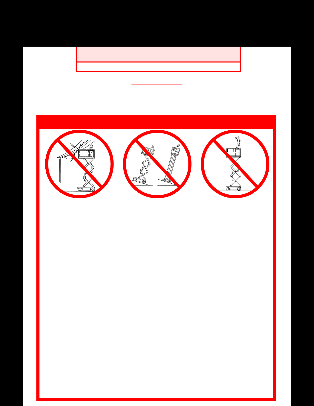
NEVER operate the machine within
ten feet of power lines. THIS
MACHINE IS NOT INSULATED.
NEVER operate the machine without first surveying the work area for surface hazards such as holes, drop-offs,
bumps and debris.
NEVER operate the machine if all guardrails are not properly in place and secured with all fasteners properly
torqued.
SECURE and lock gate after mounting platform.
KEEP all body parts clear of outriggers when extending or retracting (outrigger equipped machines only).
NEVER use ladders or scaffolding on the platform.
NEVER attach overhanging loads or increase platform size.
MAINTAIN tire pressure at 50 psi. Check daily.
LOOK up, down and around for overhead obstructions and electrical conductors.
DISTRIBUTE all loads evenly on the platform. See the back cover for maximum platform load.
NEVER use damaged equipment. (Contact UpRight for instructions. See toll-free phone number on back cover.)
NEVER change operating or safety systems.
INSPECT the machine thoroughly for cracked welds, loose hardware, hydraulic leaks, damaged control cable,
loose wire connections and wheel bolts.
NEVER climb down elevating assembly with the platform elevated.
NEVER perform service on machine while platform is elevated without blocking elevating assembly.
NEVER recharge battery near sparks or open flame; batteries that are being charged emit highly explosive
hydrogen gas.
Safety Rules and Operating Instructions
AFTER USE secure the work platform against unauthorized use by turning chassis key switch off and removing
key.
NEVER replace any component or part with anything other than original UpRight replacement parts without the
manufacturer's written consent.
Gasoline and diesel engine exhaust and some of their constituents are known to the State of Califor-
nia to cause cancer, birth defects, and other reproductive harm.
NEVER elevate or drive elevated on
uneven slopes or soft ground or elevate the platform unless the platform is level.
California Proposition 65 Warning
1
NEVER sit, stand or climb on
guardrail or midrail.
Page 2
Introduction
This manual covers Electric and Bi-Energy models
of the LX Series Work Platforms. Both machines
operate on a 48 volt battery powered system. The
Bi-Energy machine uses a diesel powered engine
to charge the batteries. Manual for engine on
BiEnergy machine is stored with thioperators
manual. These manuals must be stored on the
machine at all times.
Pre-Operation and Safety
Inspection
Carefully read, understand and follow all safety
rules, labels, and operating instructions, then
perform the following steps each day before use.
Perform a complete visual inspection of the entire
unit prior to operating.
1. Open panels and check hydraulic components
and hoses for damage or leaks. Check electrical
components and wiring for damage or loose
connections.
2. Inspect chassis, axles, hubs, and steering
linkage for damage, deformation, buckeled
paint, loose or missing hardware, and cracked
welds.
3. With platform fully lowered, check the hydraulic oil level sight gauge on the hydraulic tank .
Add ISO #46 hydraulic oil if necessary.
4. Check that fluid level in all batteries is correct
(See Battery Maintenance, Page 8).
5. Check the engine oil level and fuel level (BiEnergy model).
6. Check that all guardrails are in place. Insure
that gate operates freely and latches securely.
7. Check tires for damage. Check tire pressure; 75
psi (5.2 bar) if equipped with pneumatic tires.
8. Carefully inspect the entire work platform for
damage such as cracked welds or structural
members, loose or missing parts, oil leaks,
damaged cables or hoses, and loose connections.
9. Bi-Energy models - While the engine is cool
check the engine coolant level.
DO NOT use a machine that is damaged
or malfunctioning. Tag and remove the
unit from service until it is repaired.
System Function Inspection
STAND CLEAR of the work platform
while performing the following checks.
Before operating the work platform survey
the work area for surface hazards such as
holes, drop-offs, bumps and debris.
Check in ALL directions, including above
the work platform, for obstructions and
electrical conductors.
Protect control console cable from possible
damage while performing checks.
1. Unhook controller from guardrail. Firmly grasp
controller handle in such a manner that the
interlock lever can be depressed, while performing the following checks from the ground.
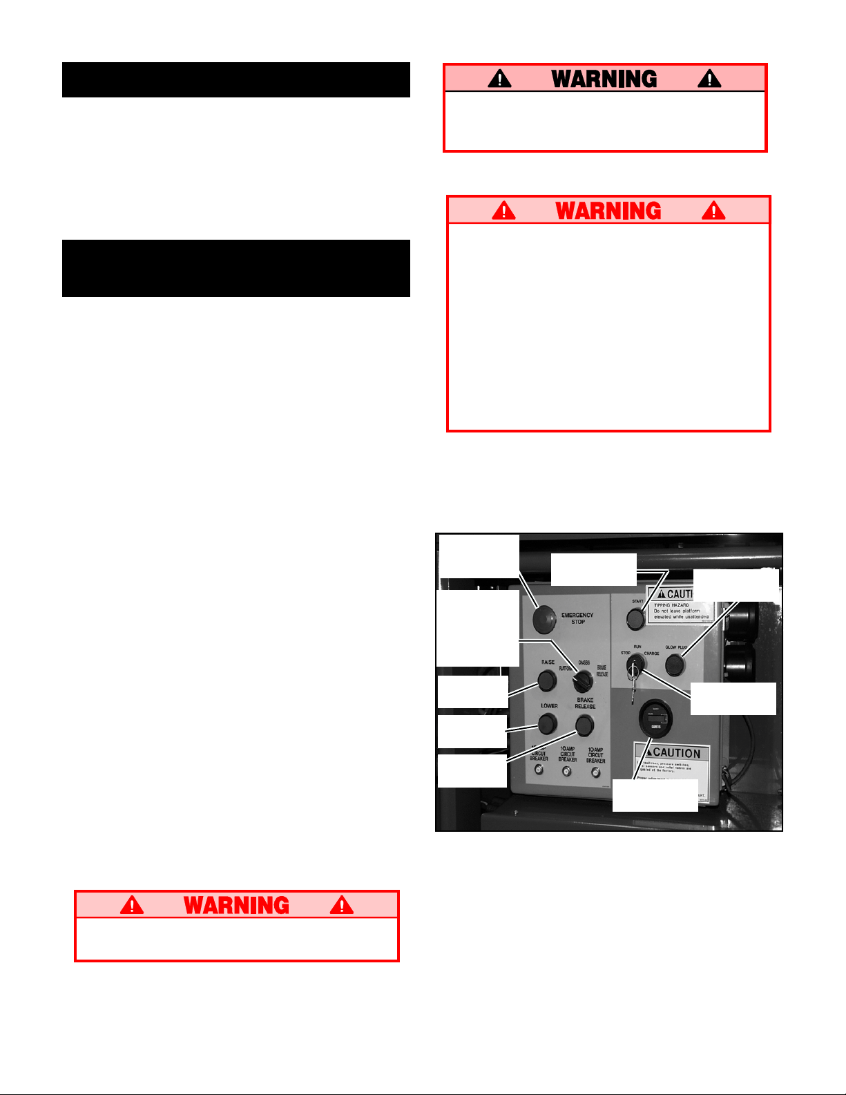
Emergency
Stop
Button
Platform/
Chassis/
Brake
Release
Switch
Raise
Lower
Brake
Release
Figure 1: Chassis control panel. Bi-Energy
controls shown, Electric model does not include
glow plug button or start button.
Start
Glow Plug
Key Switch
Hour Meter
NEVER remove the cap from a hot radiator. Hot coolant can cause severe burns.
2
Page 3
NOTE: Bi-Enery machine may be powered by
batteries or by engine. To power the machine by
engine, turn platform or chassis key on, press
engine start button to crank the engine. Release
button when engine starts. If engine is cold, press
the glow plug button for six seconds proir to
starting.
IMPORTANT: Bi-Energy models - If starting
engine from platform be sure engine switch on
chassis control panel is set to "RUN".
2. Turn platform controller key switch clockwise
to ON.
3. Position drive/lift switch to DRIVE position.
Drive enable indicator light will be illuminated.
4. With the speed range switch first in LOW
SPEED and then again in HIGH SPEED de-
press the interlock lever and slowly push the
control lever to FORWARD then REVERSE
positions to check for speed and directional
control. The farther you push or pull the control lever the faster the machine will travel.
5. Push steering switch RIGHT then LEFT to
check for steering control.
6. Hook controller on guardrail in original position.
7. On chassis controls, turn key switch to
CHAS-
SIS.
8. From lower controls, push chassis raise button
to elevate platform while pushing the tilt sensor
(Figure 3) off of level. The platform should only
partially elevate and the tilt alarm should sound.
If the platform continues to elevate and/or there
is no alarm STOP and remove the machine from
service until it is repaired.
9. Release the tilt sensor and fully elevate platform.
10. Visually inspect the elevating assembly, lift
cylinder, cables and hoses for damage or erratic
operation. Check for missing or loose parts.
11. Lower the platform partially by pushing in on the
chassis lower switch, and check operation of the
audible lowering alarm.
12. Open the chassis emergency lowering valve
(Figure 4) to check for proper operation by
pulling and holding the knob out. Once the
platform is fully lowered, close the valve by
releasing the knob.
13. On chassis controls, turn key switch to
PLAT-
FORM.
14. Mount the platform making sure the gate is latched.
15. Turn platform controller key switch clockwise to
ON. Position drive/lift switch to LIFT.
16. Depress the interlock lever and slowly push the
control lever to RAISE to raise the platform,
fully actuate the control lever to check proportional lift speed. Elevate the platform to 12 feet
(3.7 m).
17. Slowly pull control lever to DOWN position to
lower platform. Check that lowering alarm
sounds.
18. Turn platform controller key switch to OFF, push
the emergency stop button and dismount the
platform.
19. Close and secure module covers.
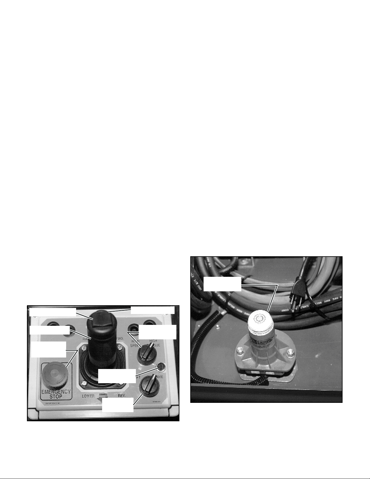
Tilt Sensor
Steering Switch
Control Lever
Emergency
Stop Switch
Drive Enable
Indicator
Lift/Drive
Switch
Figure 2: Controller
Interlock Lever
Speed Range
Switch
Figure 3: Tilt Sensor
3
Page 4

Operation
Before operating work platform, ensure that the
pre-operation and safety inspection has been
completed, any deficiencies have been corrected
and the operator has been thoroughly trained on
this machine.
NOTE: Bi-Energy machine may be powered by
batteries or by engine. To power the machine by
engine, press engine start button to crank the
engine. Release button when engine starts. If
engine is cold, press the glow plug button on
chassis control box for six seconds prior to starting.
IMPORTANT: If starting engine from platform
be sure engine switch on chassis is set to "RUN".
Travel With Platform Lowered
7. Grasp the control lever so the interlock lever is
depressed (releasing the interlock lever cuts
power to controller). Slowly push or pull the
control lever to FORWARD or REVERSE to
travel in the desired direction. The farther you
push or pull the control lever from center the
faster the machine will travel.
8. While moving, push the drive/lift speed range
switch to HIGH SPEED for travel on level
surfaces or to LOW SPEED for climbing grades
or traveling in confined areas.
Steering
1. Push the steering switch RIGHT or LEFT to
turn the wheels. Observe the tires while
maneuvering to insure proper direction.
Note: Steering is not self-centering. Wheels must
be returned to the straight ahead position by
operating the steering switch.
1. Verify chassis emergency stop switch is in the
ON position (pulled out), the drive enable
indicator light is on, and that the platform/
chassis switch is on PLATFORM.
Note: If the drive enable indicator light is off,
verify that the platform is fully lowered.
2. After mounting platform, close and latch gate.
Check that guardrails are in position and properly assembled with fasteners properly torqued.
3. Check that route is clear of persons, obstructions, holes and drop-offs and surface is
capable of supporting the wheel loads.
4. Check clearances above, below and to the sides
of the platform.
5. Pull controller emergency stop button out to
ON position.
6. Set the drive/lift speed range switch to LOW
SPEED.
Raising and Lowering the Platform
1. Position the drive/lift switch to LIFT.
2. While holding the control lever so the interlock
lever is depressed, push the control lever
slowly to UP to raise the platform. Pushing the
control lever farther increases the lift speed.
3. Lower the platform by pulling back on the
control lever until the platform is fully lowered.
4
Page 5

Travel with Work Platform Elevated
Travel with platform elevated ONLY on firm and
level surfaces.
Note: The work platform will travel at reduced
speed when in the elevated position, and only
when the front axle is parallel with the rear axle.
1. Check that the route is clear of persons, obstructions, holes and drop-offs, surface is level
and capable of supporting the wheel loads.
2. Check clearances above, below and to the sides
of platform.
3. Position the drive/lift switch to the DRIVE
position.
4. Push the control lever to FORWARD or RE-
VERSE for the desired direction of travel.
If the machine quits driving and the tilt alarm
sounds, immediately lower the platform and
move the machine to a level location before reelevating the platform.
Emergency Lowering
The emergency lowering knob is located at the
front of the machine at the base of the scissor
assembly (Figure 4).
1. Open the emergency lowering valve by pulling
on the knob and holding it.
2. Once the platform is fully lowered, release the
knob to close the valve.
After Use Each Day
1. Ensure that the platform is fully lowered.
2. Park the machine on level ground, preferably
under cover, secure against vandals, children
or unauthorized operation.
3. Turn the key switch to OFF and remove the
key to prevent unauthorized operation.
Parking Brake Release (Figure 5)
Perform the following only when the machine will
not operate under its own power and it is necessary to move the machine or when winching onto
a trailer to transport.
Never release brakes if machine is on a
slope. Hook machine to towing vehicle
before releasing brakes.
1. Turn Platform/Chassis/Brake Release switch
to Brake Release position. Alarm will sound.
2. Momentarily push brake Release button.
3. The machine will now roll when pushed or
pulled.
4. For normal operation, turn Platform/Chassis/
Brake Release switch to Platform position.
Never operate work platform with the
parking brakes released. Serious injury or
damage could result.
Emergency
Lowering
Knob
Figure 4: Emergency Lowering Knob
Brake
Release
Figure 5: Parking Brake Release Button
5
Page 6

Fold Down Guardrails
This procedure is only for passing through doorways. Guardrails must be returned to proper
position before using the machine.
Fold Down Procedure (Figure 6)
Note: When performing the following procedures retain all fasteners.
1. Place controller on platform.
2. Starting at the front of the platform, remove
nuts, bolts and washers from the top of the
front guardrail. Fold the front guardrail down
onto the platform.
3. Close and latch the gate.
4. Remove nuts, bolts and washers from the top
of the rear guardrail. Fold the rear guardrail
down onto the platform being careful to keep
gate latched at all times.
5. Remove nuts, bolts and washers from the top
of the side guardrails and from the slideout
deck midrail. Lift up and fold one side guardrail in so it rests on the deck. Repeat with other
side guardrails.
Erection Procedure
IMPORTANT: After guardrails have been completely assembled, torque all hardware to values
specified in torque chart on page 10.
1. Raise side guardrails making sure each is
pushed down to secure the guardrail in the
vertical position.
2. Install bolts, washers and nuts between the side
guardrails.
3. Raise rear guardrail assembly, aligning holes
and install bolts, washers and nuts.
4. Raise front guardrail, aligning holes and install
bolts, washers and nuts.
5. Hang controller on front guardrail.
6. Before operating work platform check that all
fasteners are in place and properly torqued.
Before operating machine, guardrails must be
securely fastened in their proper position.
Double Deck Fold Down Procedure
(Figure 7)
Figure 6: Fold Down Guardrails
NOTE: When performing the following procedures retain all fasteners.
1. Place controller on platform.
2. Starting at the front ; slide out deck, remove
hardware from top front corners of guardrails.
Remove hardware from the slide out deck side
guardrail midrails. Also remove hardware from
the top of the sockets that hold the slide out
deck side guardrails to the deck. Fold the side
guardrails down onto the platform.
3. Follow step 2 to fold the front side guardrails
on the rear slide out deck.
4. Unlatch the gate so the left side guardrails can
be folded down in two separate pieces. Also
remove the hardware opposite the gate latch on
the right side guardrail so it can be separated
into two pieces.
5. Lift up and fold side guardrails in so they rest
on the deck.
6. Lift up and fold front guardrail in so it rests on
the deck. Repeat for rear guardrail.
6
Page 7

Double Deck Erection Procedure
IMPORTANT: After guardrails have been
completely assembled, torque all hardware to
values specified in torque chart on page 10.
1. Raise front guardrail making sure it is pushed
down to secure the guardrail in the vertical
position. Repeat for rear guardrail.
2. Raise guardrails making sure each is pushed
down to secure the guardrail in the vertical
position. Align holes and install hardware.
3. Raise one of the four slide out deck side guardrail assemblies. Align holes and install
hardware. Repeat this procedure for the other
three slide out deck side guardrails.
4. Hang controller on front guardrail.
5. Before operating work platform, check that all
fasteners are in place and properly torqued.
Transporting Work Platform
By Crane
1. Secure straps to chassis tie down/lifting lugs
only (Figure 8).
By Truck
1. Maneuver the work platform into transport
position and chock wheels.
2. Secure the work platform to the transport
vehicle with chains or straps of adequate load
capacity attached to the chassis tie down/lifting
lugs (Figure 8).
Overtightening of chains or straps through
tie down lugs may result in damage to
work platform.
step 2
step 6
step 5
step 3
Note: Illustration above is shown with decks
extended for clarity. Perform this procedure
with guardrails retracted.
Figure 7: Fold Down Guardrails (Double Deck)
Figure 8: Transporting Work Platform
7
Page 8

Maintenance
Never perform service on the work platform in the elevating assembly area while
platform is elevated without first blocking
the elevating assembly.
DO NOT stand in elevating assembly area
while deploying or storing brace.
Blocking Elevating Assembly (Figure 9)
Installation
Upper Scissor
Center Pivot
1. Park the work platform on firm level ground.
2. Verify platform emergency stop switch is ON.
3. Turn platform/chassis switch to CHASSIS.
4. Elevate platform far enough to allow brace to
be lowered.
5. From the left side of the machine, disengage
the locking pin securing the brace. Rotate the
scissor brace counterclockwise until it is vertical
and between the two scissor center pivots.
6. Slowly lower platform until brace is supporting
the platform.
Removal
1. Using chassis controls, raise platform until the
scissors brace clears the two scissor center
pivots.
2. Rotate scissors brace clockwise until the locking
pin engages. Verify locking pin is engaged.
3. Lower platform completely.
Brace
Locking Pin
Figure 9: Blocking Elevating Assembly
Lower Scissor
Center Pivot
Battery Maintenance
Hazard of explosive gas mixture. Keep
sparks, flame and smoking materials away
from batteries.
Always wear safety glasses when working
with batteries.
Battery fluid is highly corrosive. Rinse
away any spilled fluid thoroughly with
clean water.
Always replace batteries with UpRight
batteries or manufacturer approved replacements weighing 120 lbs. (54.4 kg.)
each.
Check battery fluid level daily, especially if work
platform is being used in a warm, dry climate.
If electrolyte level is lower than 3/8 in. (10 mm)
above plates add distilled water only. DO NOT
use tap water with high mineral content it will
shorten battery life.
Keep terminals and tops of batteries clean.
Refer to the Service Manual to extend battery life
and for complete service instructions.
8
Page 9

Routine Service
Use the following table as a guide for routine
maintenance. Inspection and maintenance shall
be performed by personnel who are trained and
familiar with mechanical and electrical procedures. Refer to the Service Manual for complete
service instructions.
Please copy this page and use the Routine Service
Table as a checklist when inspecting a machine for
service.
Routine Service Table
Routine Service Table Key
Interval
Daily=each shift (every day) or every eight hours
30d=every month (30 days) or every 50 hours
3m=every 3 months or 125 hours
6m=every 6 months or 250 hours
1y=every year or 500 hours
2y=every 2 years or 1000 hours
Y=Yes/Acceptable
N=No/Not Acceptable
R=Repaired/Acceptable
COMPONENT INSPECTION OR SERVICES INTERVAL Y N R
Engine Oil Check level and condition Daily
BiEnergy Check for leaks Daily
Models Change oil & filter 100
Engine Fuel Check fuel level Daily
System Check for leaks Daily
BiEnergy Replace fuel filter 100
Models Check air cleaner Daily
Main Check electrolyte level Daily
Battery Check specific gravity 30
Pack Clean exterior 6
Engine Check electrolyte level Daily
Battery Check specific gravity 30
System Clean exterior 6
BiEnergy Check battery cable condition Daily
Models Clean terminals 6
Engine Check coolant level (with engine cold) Daily
Coolant Replace coolant 2y
Hydraulic Check oil level Daily
Oil Change filter 6
Hydraulic Check for leaks Daily
System Check hose connections 30
Emergency Open the emergency lowering Daily
Hydraulic valve and check for
System serviceability
Controller Check switch operation Daily
Control Check the exterior of the cable Daily
Cable for pinching, binding or wear
Platform Check fasteners for proper torque Daily
Deck and Check welds for cracks Daily
Rails Check condition of deck Daily
Tires Check for damage Daily
Hydraulic Wipe clean 30
Pump Check for leaks at mating surfaces 30
Drive Motors
Steering Check hardware & fittings 6
System for proper torque
Check battery cable condition Daily
Clean terminals 6
Drain and replace oil 2
Check hoses for exterior wear 30
Check air pressure (75psi [5.2 bar]) Daily
Check lug nuts (torque to 150 ft. lbs. [205 Nm]) 30
Check for hose fitting leaks Daily
Check mounting bolts for proper torque 30
Check for operation and leaks Daily
Oil all pivot points 30
Check steering cylinder for leaks & 30
mounting bolts for proper torque
HOURS
HOURS
D
M
M
D
M
M
M
Y
D
D
D
D
D
D
M
D
D
COMPONENT INSPECTION OR SERVICES INTERVAL Y N R
Elevating Inspect for structural cracks Daily
Assembly Check pivot points for wear 30
Check pivot pin mounting bolts 30
for proper torque
Check scissor arms for bending 6
Grease scissor pins 30
Chassis Check hoses for pinch or Daily
rubbing points
Check component mounting 6
for proper torque
Check welds for cracks Daily
Lift Check the cylinder rod for wear 30
Cylinder Check pivot pin mounting bolts 30
for proper torque
Check seals for leaks 30
Inspect pivot points for wear 30
Check fittings for proper torque 30
Axle Check the cylinder rod for wear 30
Cylinder Check mounting pin pivot bolts 30
for proper torque
Check seals for leaks 30
Inspect pivot points for wear 30
Check fittings for proper torque 30
Entire Check for and repair Daily
Unit collision damage
Check fasteners for proper torque 3
Check for corrosion-remove 6
and repaint
Lubricate 30
Labels Check for peeling, missing, or unreadable Daily
labels & replace
D
D
M
D
M
D
D
D
D
D
D
D
D
D
D
M
M
D
Service Report
Date: _______________
Owner: ___________________________________
Model No:_____________ Serial No: __________
Serviced By: _______________________________
Service Interval: ___________________________
9
Page 10

NOTES:
10
Page 11

1-REQUIRED
66554-000-00
66558-000
2-REQUIRED
66561-001
1-REQUIRED
61515-001
1-REQUIRED
Load 3900 lbs.
Maximum Wheel
101252-013
And/Or Outrigger
Maximum Wheel
And/Or Outrigger
1 REQ. LX31
Load 4200 lbs.
101252-014
1 REQ. LX31
66568-000
1-REQUIRED
66558-000
2-REQUIRED
66555-000
1-REQUIRED
60197-000
1-REQUIRED
66551-003
1-REQUIRED
66550-009
1-REQUIRED
For machines equipped with options consult Service Manual.
67642-002
1-REQUIRED
or 5 occupants
Maximum Distributed
Platform Load 2000 lbs
Maximum side load 300 lbs
66557-010
2-REQ. LX31 ONLY
or 5 occupants
Maximum Distributed
Platform Load 1500 lbs
Maximum side load 250 lbs
62562-002
66557-007
2-REQ. LX41 ONLY
1-REQUIRED
66552-000
1-REQUIRED
61205-000
1-REQUIRED
27898-000
1-REQUIRED
BI-ENERGY MODELS ONLY
63423-000
1-REQUIRED
61220-001
1-REQUIRED
67638-002
1-REQUIRED
66551-002
1-REQUIRED
66555-000
1-REQUIRED
67639-001
1-REQUIRED
BI-ENERGY MODELS ONLY
10076-001
1-REQUIRED
66562-001
1-REQUIRED
Note: Labels can be ordered by using Part Number located by each label.
LX SERIES LABEL INSTALLATION: THESE LABELS SHALL BE PRESENT AND IN GOOD
CONDITION BEFORE OPERATING THE WORK PLATFORM. BE SURE TO READ,
UNDERSTAND AND FOLLOW THESE LABELS WHEN OPERATING THE WORK
PLATFORM.
11
Page 12

Specifications*
ITEM
Platform Size
Standard
w/ Extension
Double Deck Models
w/ Decks Retracted
w/ Decks Extended
Max. Platform Capacity
Standard
w/ Extension
on Extension
Double Deck Models
on Extension (one end only)
Max. No. of occupants
Standard
on Extension
Double Deck Models
on Extension (one end only)
Height
Working Height
Max. Platform Height
Min. Platform Height
Dimensions
Weight, Electric
Overall Width
Overall Height
Overall Length, Standard
Driveable Height
Surface Speed
Platform Lowered
Platform Raised
System Voltage
Hydraulic Tank Capacity
Maximum Hydraulic System Pressure
Hydraulic Fluid
Normal Use (>32 °F [0 °C])
Low Temp. Use
(-10 to 32 °F [-23 to 0 °C])
Lift System
Lift Speed
Power Source
Drive Control
Control System
Horizontal Drive
Tires Standard
Parking Brakes
Turning Radius (inside)
Maximum Gradeability
Wheel Base
Guardrails
Toeboard
( Inside Toeboards)
BiEnergy
Electric w / Extension
BiEnergy
Electric Double Deck
BiEnergy
Optional
LX31
143.38 in. x 70 in. [3.64 m x 1.78 m]
179.38 in. x 68 in. [4.56 m x 1.73 m]
156in. x 68 in. [3.96 m x 1.73 m]
228 in. x 68 in. [5.79 m x 1.73 m]
2000 lbs. [907 kg]
2000 lbs. [907 kg]
500 lbs. [227 kg] 1750
lbs [795 kg] 500
lbs. [227 kg]
8 people
2 people
8 people
2 people
37 ft. [11.28 m]
31 ft. [9.45 m]
56.3 in. [1.43 m]
2WD: 9,920 lbs. [4,500 kg]
2WD: 10,120 lbs. [4,590 kg]
2WD: 10,350 lbs. [4,695 kg]
2WD: 10,550 lbs. [4,785 kg]
2WD: 10,780 lbs. [4,890 kg]
2WD: 10,980 lbs. [4,981 kg]
90 in. [2.29 m]
99.75 in. [2.53 m]
160.5 in. [4.08 m]
31 ft. [9.45 m]
0 to 3.1 mph [0 to 5.0 km/h]
0 to 0.3 mph [0 to .48 km/h]
48 Volt DC
28.3 Gallons [107.13 l]
3000 psi [206.8 bar]
ISO #46
ISO #32
One Single Stage Lift Cylinder
Raise, 40 sec./Lower, 60 sec.
Eight 6V 350 AH Batteries
(BiEnergy) One Kubota 12 HP Diesel
Proportional
Smooth one hand Joystick
Two Electric Wheel Motors
10-16.5 NHS 8 Ply, 75psi [5.2 bar]
Poly Filled
Two, Spring Applied, Hydraulic Release,
Multiple Disc
48 in. [1.22 m]
2WD: 30% [16.7º]
115.75 in. [2.94 m]
43.5 in. [1.1 m] high, Fold Down with Self
Closing Gate
6 in. [152 mm] High
LX41
143.38 in. x 70 in. [3.64 m x 1.78 m]
179.38 in. x 68 in. [4.56 m x 1.73 m]
156 in. x 68 in. [3.96 m x 1.73 m]
228 in. x 68 in. [5.79 m x 1.73 m]
1,500 lbs. [680 kg]
1,500 lbs. [680 kg]
500 lbs. [227 kg]
1250 lbs {567 kg]
500 lbs. [227 kg]
6 people
2 people
6 people
2 people
47 ft. [14.33 m]
40 ft. 6 in. [12.34 m]
65.3 in. [1.66 m]
2WD: 11,260 lbs. [5,108 kg]
2WD: 11,460 lbs. [5,194 kg]
2WD: 11,690 lbs. [5,303 kg]
2WD: 11,890 lbs. [5,371 kg]
2WD: 12,120 lbs. [5,498 kg]
2WD: 12,318 lbs. [5,587 kg]
90 in. [2.29 m]
108.75 in. [2.76 m]
160.5 in. [4.08 m]
40 ft. 6 in. [12.34 m]
0 to 3.1 mph [0 to 5.0 km/h]
0 to 0.3 mph [0 to .48 km/h]
48 Volt DC
28.3 Gallons [107.13 l]
3000 psi [206.8 bar]
ISO #46
ISO #32
One Single Stage Lift Cylinder
Raise, 50 sec./Lower, 70 sec.
Eight 6V 350 AH Batteries
(BiEnergy) One Kubota 12 HP Diesel
Proportional
Smooth one hand Joystick
Two Electric Wheel Motors
10-16.5 NHS 8 Ply, 75psi [5.2 bar]
Poly Filled
Two, Spring Applied, Hydraulic Release,
Multiple Disc
48 in. [1.22 m]
2WD: 30% [16.7º]
115.75 in. [2.94 m]
43.5 in. [1.1 m] high, Fold Down with Self
Closing Gate
6 in. [152 mm] High
Safety Rules and Operating Instructions
* Specifications subject to change without notice.
Hot weather or heavy use may reduce performance.
Refer to Service Manual for complete parts and service information.
Meets or exceeds all applicable requirements of OSHA and ANSI A92.6-1999
FOR MORE INFORMATION
Local Distributor:
Safety Rules and Operating Instructions
TEL: (800) 926-5438 or (559) 891-5200
FAX: (559) 896-9012
PARTS: (888) UR-PARTS
PARTSFAX: (559) 896-9244
1775 Park St., Selma, CA 93662
http://www.upright.com
12
067449-001
3/00 D
 Loading...